


ENGLISH
®
ALPHA SPOT HPE 700 C61355
INSTRUCTION MANUAL
|
INDEX |
|
|
Page |
Contents |
|
|
2 |
Safety information |
|
|
3 |
Unpacking and preparation |
|
|
4 |
Installation and start-up |
|
|
5 |
Control panel |
|
|
7 |
Menu setting |
|
|
14 |
Maintenance |
|
|
22 |
Technical information |
|
|
22 |
Cause and solution of problems |
|
|
23 |
Channel functions |
|
|
Congratulations on choosing a Clay Paky product! We thank you for your custom.
Please note that this product, as all the others in the rich Clay Paky range, has been designed and made with total quality to ensure excellent performance and best meet your expectations and requirements.
Carefully read this instruction manual in its entirety and keep it safe for future reference. It is essential to know the information and comply with the instructions given in this manual to ensure the fitting is installed, used and serviced correctly and safely.
CLAY PAKY S.p.A. disclaims all liability for damage to the fitting or to other property or persons deriving from installation, use and maintenance that have not been carried out in conformity with this instruction manual, which must always accompany the fitting.
CLAY PAKY S.p.A. reserves the right to modify the characteristics stated in this instruction manual at any time and without prior notice.
1
700W 3
IP20
LiFePO4
Pb
SAFETY INFORMATION
• Installation
Make sure all parts for fixing the projector are in a good state of repair. Make sure the point of anchorage is stable before positioning the projector.
The safety chain must be properly hooked onto the fitting and secured to the framework, so that, if the primary support system fails, the fitting falls as little as possible.
If the safety chain gets used, it needs to be replaced with a genuine spare.
• Minimum distance of illuminated objects
The projector needs to be positioned so that the objects hit by the beam of light are at least 3 metres (10’ 9 )”from the lens of the projector.
• Minimum distance from flammable materials
The projector must be positioned so that any flammable materials are at least 0.20 metres (8") from every point on the surface of the fitting.
• Mounting surfaces
It is permissible to mount the fitting on normally flammable surfaces.
• Maximum ambient temperature
Do not operate the fixture if the ambient temperature (Ta) exceeds 40° C (104° F).
• IP20 protection rating
The fitting is protected against penetration by solid bodies of over 12mm (0.47”) in diameter (first digit 2), but not against dripping water, rain, splashes or jets of water (second digit 0).
• Protection against electrical shock
Connection must be made to a power supply system fitted with efficient earthing (Class I appliance according to standard EN 60598-1).
It is, moreover, recommended to protect the supply lines of the projectors from indirect contact and/or shorting to earth by using appropriately sized residual current devices.
• Connections to mains supply
Connection to the electricity mains must be carried out by a qualified electrical installer.
Check that the mains frequency and voltage correspond to those for which the projector is designed as given on the electrical data label.
This label also gives the input power to which you need to refer to evaluate the maximum number of fittings to connect to the electricity line, in order to avoid overloading.
• Temperature of the external surface
The maximum temperature that can be reached on the external surface of the fitting, in a thermally steady state, is 150°C (302°F).
• Maintenance
Before starting any maintenance work or cleaning the projector, cut off power from the mains supply.
After switching off, do not remove any parts of the fitting for at least 10 minutes. After this time the likelihood of the lamp exploding is virtually nill. If it is necessary to replace the lamp, wait for another 20 minutes to avoid getting burnt.
The fitting is designed to hold in any splinters produced by a lamp exploding. The lenses must be mounted and, if visibly damaged, they have to be replaced with genuine spares.
• Lamp
The fitting mounts a high-pressure lamp that needs an external igniter. This igniter is fitted onto the apparatus.
-Carefully read the "operating instructions" provided by the lamp manufacturer.
-Immediately replace the lamp if damaged or deformed by heat.
• Battery
This product contains a rechargeable lead-acid or lithium iron tetraphosphate battery. To preserve the environment, please dispose the battery at the end of its life according to the regulation in force.
The products to which this manual refers comply with the European Directives pursuant to:
• 2006/95/EC |
- Safety of electrical equipment supplied at low voltage (LVD) |
• 2004/108/EC - Electromagnetic Compatibility (EMC) |
|
• 2011/65/EU |
- Restriction of the use of certain hazardous substances (RoHS) |
ALPHA SPOT HPE 700 |
2 |
UNPACKING AND PREPARATION
1
IST00B/001
2 x 183102/805
Lamp 700W
(fitted into projector)
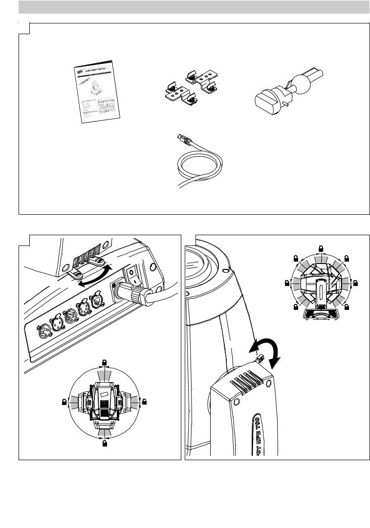
Packing contents - Fig. 1
2 |
|
|
UNLOCKED |
LOCKED |
|
° |
9 |
0 |
0 |
9 |
° |
|
|
° |
9 |
0 |
0 |
9 |
° |
PAN Mechanism Lock and Release (every 90°) - Fig. 2
TILT Mechanism Lock and Release (every 45°) - Fig. 3
ALPHA SPOT HPE 700
3 |
|
|
|
|
|
° |
4 |
5 |
|
5 |
|
° |
||
4 |
|
|
|
|
° |
|
|
|
45° |
5 |
|
|
|
|
4 |
|
|
|
|
45° |
|
|
|
4 |
|
|
|
5 |
|
|
|
|
|
° |
LOCKED |
|
|
|
|
UNLOCKED |
|
|
|
|
3 |
|
|
|
|

INSTALLATION AND START-UP
4 |
Installing the projector - Fig. 4
The projector can be installed on the floor resting on special rubber feet, on a truss or on the ceiling or wall.
WARNING: with the exception of when the projector is positioned on the floor, the safety cable must be fitted. (Cod. 105041/003 available on request). This must be securely fixed to the support structure of the projector and then connected to the fixing point at the centre of the base.
5 |
1 |
2 |
2 |
3 |
1 |
Connecting and disconnecting power cable - Fig. 5
ALPHA SPOT HPE 700 |
4 |
CONTROL PANEL
6 |
Mains |
L |
|
||
|
N |
|
|
|
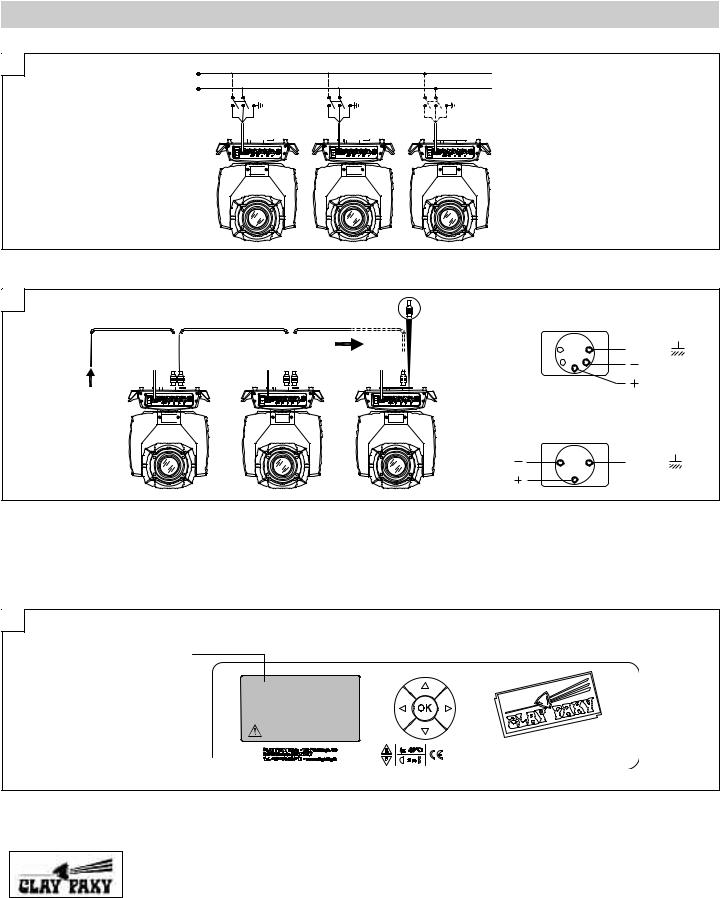
Connecting to the mains supply - Fig. 6
7 |
DMX 512 |
|
|
|
5 PIN |
|
|
|
5 |
1 |
SCREEN |
|
4 3 |
2 |
SIGNAL |
|
|
|
|
|
|
|
SIGNAL |
DMX 512 |
|
|
|
|
DMX 512 |
|
|
|
3 PIN |
|
|
SIGNAL |
2 |
1 |
SCREEN |
SIGNAL |
3 |
|
|
|
|
|
|
Connecting to the control signal line (DMX) - Fig. 7
Use a cable conforming to specifications EIA RS-485: 2-pole twisted, shielded, 120Ohm characteristic impedance, 22-24 AWG, low capacity. Do not use microphone cable or other cable with characteristics differing from those specified. The end connections must be made using XLR type 3 or 5-pin male/female connectors. A terminating plug must be inserted into the last projector with a resistance of 120Ohm (minimum 1/4 W) between terminals 2 and 3.
IMPORTANT: The wires must not make contact with each other or with the metal casing of the connectors. The casing itself must be connected to the shield braid and to pin 1 of the connectors.
8
Fixture ID
Dmx Address |
2 |
1 |
|
||
|
|
Warning Message
Switching on the projector - Fig. 8
Press the switch. The projector starts resetting the effects. At the same time, the following information scrolls on the display:
Model |
|
Firmware |
|
xxx (Fixture ID) |
|
System errors |
Alpha SPOT |
|
Version X.X.X |
|
Dmx Address xxx |
|
E: ......................... |
HPE 700 |
|
Date - Hour |
|
|
|
W: ......................... |
|
|
|
|
|
|
|
On conclusion of resetting in case of absence of the dmx signal, Pan and Tilt move to the “Home” position (Pan 50% - Tilt 50%). The control panel (Fig. 8) has a display and buttons for the complete programming and management of the projector menu. The display can be in one of two conditions: rest status and setting status. When it is in the rest status, the display shows the projector’s DMX address and the Fixture ID address (if set).
During menu setting status, after a wait time (about 30 seconds) without any key having been pressed, the display automatically returns to rest status. It should be noted than when this condition occurs, any possible value that has been modified but not yet confirmed with the Fkey will be cancelled.
Continue
ALPHA SPOT HPE 700 |
5 |

9 |
|
28 |
28 |
Reversal of the display - Fig. 9
To activate this function, press UP Band DOWN Ckeys simultaneously while the display is in the rest mode. This status will be memorised and maintained even for the next time it will be switched on. To return to the initial state, repeat the operation all over again.
Setting the projector starting address
On each projector, the starting address must be set for the control signal (addresses from 1 to 512). The address can also be set with the projector switched off.
Setting the address: see pag. 8.
Setting the projector Fixture ID
On each projector, the Fixture ID address must be set for an easy identification of the fixtures in an installation (ID from 1 to 255). The Fixture ID address can be set with the projector switched off.
Setting the Fixture ID: see pag. 8.
Functions of the buttons - Using the menu
F Confirms the displayed value, or activates the displayed function, or enters the successive menu.
C Decreases the value displayed (with auto-repetitions) or passes to the next item in the menu.
DOWN
B Increases the value displayed (with auto-repetitions) or passes to the previous item in a menu.
UP
D Return to the top level
LEFT
E Commute from units, tens, hundreds, in the "Address", "Fixture ID" and "Calibration" menù.
RIGHT
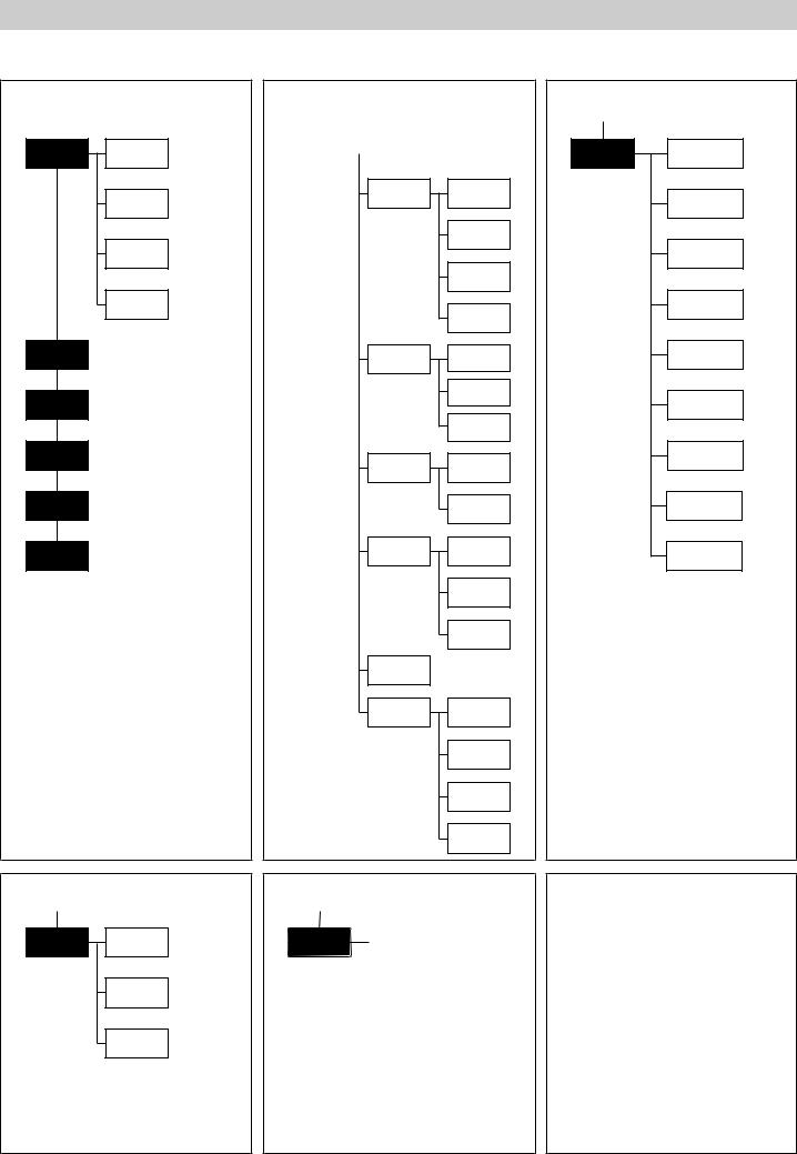
USING THE MENU:
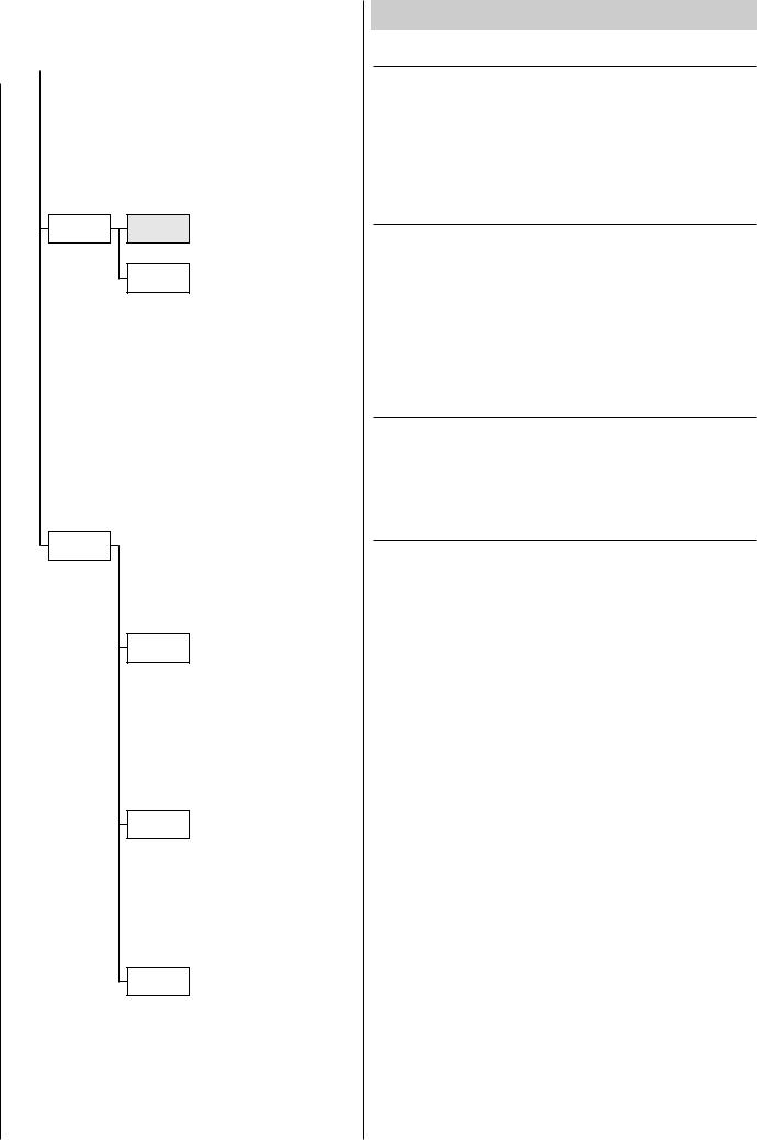
1)Press Fonce – “Main Menu” appears on the display.
2)Use the UP Band DOWN Ckeys to select the menu to be used:
•Setup (Setup Menu): To set the setting options.
•Option (Option Menu): To set the operating options
•Informations (Informations Menu): To read the counters, software version and other information.
•Manual Control (Manual control Menu): To trigger the test and manual control functions.
•Test (Test Menu): To check the proper functionning of effects
•Advanced (Advanced Menu): Access to the "Advanced menu" is recommended for a trained technical personnel. To enable the "Advanced" see pag. 13.
3)Press Fto display the first item in the selected menu.
4)Use the UP Band DOWN Ckeys to select the MENU items.
Setting addresses and options with the projector disconnected
The projector’s DMX address, as well as other possible operating options, can also be set when the appliance is disconnected from the electricity supply. All that is needed is to press Fto momentarily activate the display and thus access the settings. Once the required operations have been carried out, the display will switch off again after a wait time of 30 seconds.
ALPHA SPOT HPE 700 |
6 |
1
Set Up
Dmx
Address
Channel
Mode
Fixture ID
Ethernet
Interface
Option
Information
Manual
Control
Test
Advanced
4
Manual
Lamp
Control
Reset
Channel
MENU SETTING
MAIN MENU
2 |
3 |
|
|
|
|
Option |
|
Lamp Dmx |
|
|
|||
|
|
|
|
Pan / Tilt
Color
Shutter
Power Mode
Display
Setting
Invert
Pan
Invert
Tilt
Swap
Pan-Tilt
Encoder
Pan-Tilt
Color
Mixing
Color mixing curve
Fixed Wheel
Shortcut
Shutter
On Error
Dimmer On
Shutter
4-700W Full fan speed
400W Low fan speed
4-700W Auto fan speed
Default
Preset
User
Preset 1
User
Preset 2
User
Preset 3
Information
System
Errors
Fixture
Hours
Lamp
Hours
Lamp
Strikes
System
Version
Board
Diagnost.
Dmx
Monitor
Fans
Monitor
Network
params
5 |
|
|
|
6 |
|
|
|
|
|
|
|
|
|
|
|
|
|
|
|
|
|
|
|
|
|
|
|
|
|
|
|
|
|
|
|
|
Test |
|
|
|
|
|
|
Access code |
|
||
|
|
Pan / Tilt |
|
Advanced |
|
|
|||||
|
|
|
|
1234 |
|
|
|||||
|
|
|
|
|
|
|
|
|
|
||
|
|
|
|
|
|
|
|
|
|
|
|
|
|
|
|
|
|
|
|
|
|
|
|
|
|
|
Colour |
|
|
|
|
|
|
|
|
|
|
|
|
|
|
|
|
|
|
|
Upload |
|
|
|
|
|
|
|
|
|
|
|
Firmware |
|
|
|
|
|
|
|
|
|
|
|
|
|
|
|
|
|
|
|
|
|
|
|
|
|
|
|
Beam |
|
|
|
|
|
|
|
|
|
|
|
|
|
|
|
|
|
|
|
|
|
|
|
|
|
|
|
|
|
|
|
|
|
|
|
|
|
|
|
|
|
|
|
|
|
|
|
|
|
|
|
|
|
|
|
Setup |
|
|
|
Gobo |
|
|
|
|
|
|
|
Model |
|
|
|
|
|
|
|
|
|
|
|
|
|
|
|
|
|
|
|
|
|
|
|
|
|
|
|
|
|
|
|
|
|
|
|
|
|
|
|
|
|
|
|
|
|
|
|
|
|
|
|
|
|
|
|
|
|
|
|
Calibration |
|
|
|
All |
|
|
|
|
|
|
|
|
|
|
|
|
|
|
|
|
|
|
|
|
|
|
|
|
|
|
|
|
|
|
|
|
Continue
ALPHA SPOT HPE 700 |
7 |
NOTE: On grey the default options
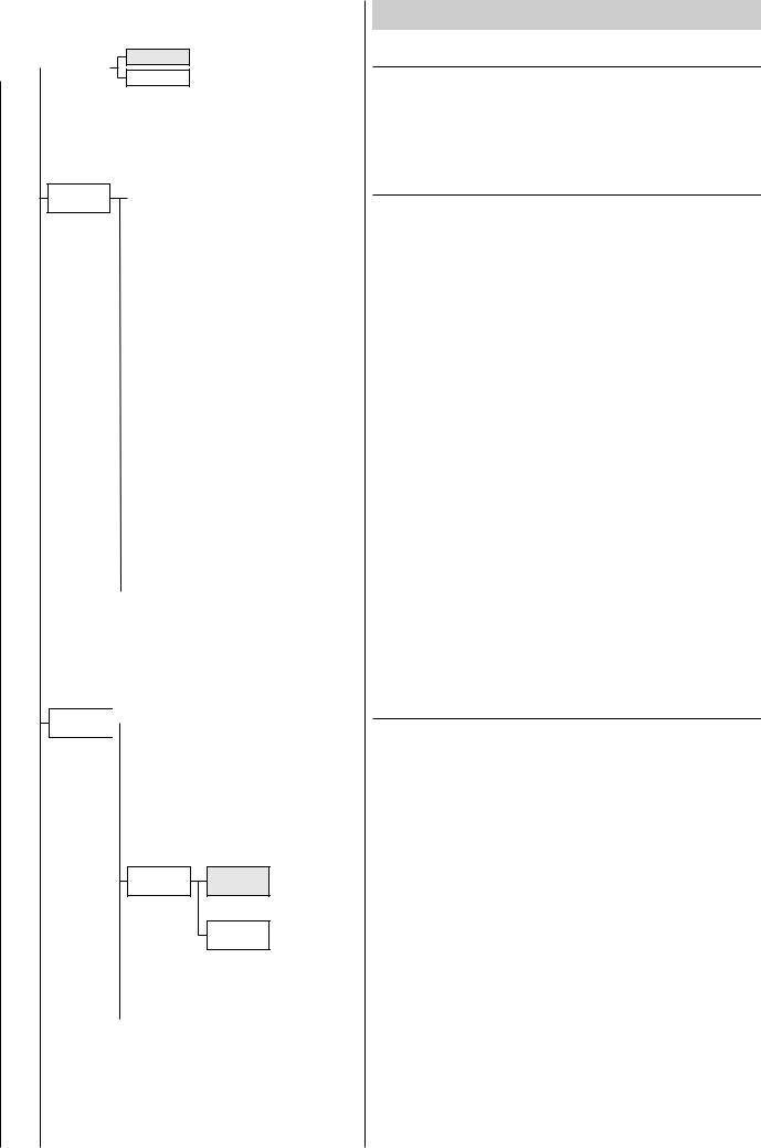
Set Up |
|
Dmx |
|
Address xxx |
|
Address |
|
||
|
|
|
|
Channel
Standard
Mode
Vector
|
Fixture ID |
|
Value xxx |
|
|
||
|
|
|
|
Ethernet
Interface
Control
Protocol
Repeat on
DMX
Universe
SET UP MENU
DMX ADDRESS
NOTE: without the DMX signal the Address (XXX) flashing
Allows you to select the DMX ADDRESS.
1)Press F- the current DMX Adress appear on the display.
2)Use the UP B and DOWN C, RIGHT E keys to plan the DMX Address.
3)Press Fto confirm the selection or LEFT Dto keep current settings.
CHANNEL MODE
Allows you to select a channel arrangement from the two available.
1)Press F - the current settings appear on the display (Standard or Vector).
2)Use the UP B and DOWN C keys to select one of the following settings:
-Standard
-Vector
3)Press Fto confirm the selection or LEFT Dto keep current settings.
FIXTURE ID
Allows you to select the FIXTURE ID.
1)Press F- the current Fixture ID appear on the display.
2)Use the UP B, DOWN C, RIGHT Ekeys to plan the Fixture ID.
3)Press Fto confirm the selection or LEFT Dto keep current settings.
ETHERNET INTERFACE
It lets you set the Ethernet settings to be attributed to the projector.
1)Premere F.
2)Use the UP Band DOWN Ckeys to select the “Ethernet Interface” options to set:
Control Protocol
It lets you select the “Control Protocol” Art-net to assign according to the control unit used:
1)Press Fthe current setting appears on the display.
2)Use the UP Band DOWN Ckeys to select one of the following settings:
-Disabled
-Art-net on IP 2
-Art-net on IP 10
3)Press Fto confirm the selection or LEFT Dto keep the current setting.
Repeat on DMX
It lets you enable the transmission of the Ethernet protocol by DMX signal to all the connected projectors.
1)Press Fthe current setting appears on the display.
2)Use the UP Band DOWN Ckeys to select one of the following settings:
-Disabled: DMX transmission disabled.
-Enabled on primary: DMX transmission enabled.
3)Press Fto confirm the selection or LEFT Dto keep the current setting.
Universe
It lets you assign the “Universe” number to be assigned to a series of projectors.
1)Press F– the current Universe address appears on the display.
2)Use the UP B, DOWN C, RIGHT Ekeys to set the Universe address.
3)Press Fto confirm the selection or LEFT Dto keep the current setting.
ALPHA SPOT HPE 700 |
8 |
|
|
|
|
Option |
|
Lamp Dmx |
|
|
|||
|
|
|
|
Pan / Tilt
Color
On
Off
|
|
|
On |
Invert |
|
|
|
|
|
|
|
Pan |
|
|
|
|
|
|
|
|
|
Off |
|
|
|
|
|
|
|
|
|
|
|
|
|
On |
|
Invert |
|
|
|
|
Tilt |
|
|
|
|
|
|
|
|
|
|
|
Off |
|
|
|
|
|
|
|
|
|
|
|
|
|
|
|
On |
|
Swap |
|
|
|
|
|
|
|
|
|
Pan-Tilt |
|
|
|
|
|
|
|
|
|
|
|
Off |
|
|
|
|
|
|
|
|
|
|
|
|
|
|
|
On |
|
Encoder |
|
|
|
|
Pan-Tilt |
|
|
|
|
|
|
|
|
|
|
|
Off |
|
|
|
|
|
|
|
|
|
|
|
|
|
|
|
Rgb |
|
Color |
|
|
|
|
|
|
|
|
|
Mixing |
|
|
|
|
|
|
|
|
|
|
|
Cmy |
|
|
|
|
|
|
|
|
|
|
|
Color
Curve 1
Mixing curve
Curve 2
|
|
|
|
On |
|
Fixwheel |
|
|
|
|
Shortcut |
|
|
|
|
|
|
|
|
|
|
|
Off |
|
|
|
|
|
|
|
|
|
|
|
ALPHA SPOT HPE 700
OPTIONS MENU
LAMP DMX
Used for enabling lamp remote control channel.
1)Press F- the current settings appear on the display (On or Off).
2)Use the UP Band DOWN Ckeys to enable (On) or disable (Off) the lamp remote control channel.
3)Press Fto confirm the selection or LEFT Dto keep current settings.
PAN / TILT
Invert pan
Used for reversing Pan movement.
1)Press F- the current settings appear on the display (On or Off).
2)Use the UP Band DOWN Ckeys to enable (On) or disable (Off) PAN inversion.
3)Press Fto confirm the selection or LEFT Dto keep current settings.
Invert tilt
Used for reversing tilt movement.
1)Press F- the current settings appear on the display (On or Off).
2)Use the UP Band DOWN Ckeys to enable (On) or disable (Off) Tilt inversion.
3)Press Fto confirm the selection or LEFT Dto keep current settings.
Swap Pan-Tilt
Used for swapping Pan and Tilt channels (as well as Pan fine and Tilt fine).
1)Press F- the current settings appear on the display (On or Off).
2)Use the UP Band DOWN Ckeys to enable (On) or disable (Off) Pan and Tilt channel swap.
3)Press Fto confirm the selection or LEFT Dto keep current settings.
Encoder Pan-Tilt
Used for enabling the Pan / Tilt encoders.
1)Press F- the current settings appear on the display (On or Off).
2)Use the UP Band DOWN Ckeys to enable (On) or disable (Off) Pan / Tilt encoders.
3)Press Fto confirm the selection or LEFT Dto keep current settings.
COLOR
Color mixing
Used for reversing the CMY color mixing system.
1)Press F- the current settings appear on the display (On or Off).
2)Use the UP Band DOWN Ckeys select one of the following settings: RGB color mixing mode
CMY color mixing mode
3)Press Fto confirm the selection or LEFT Dto keep current settings.
Color mixing curve
It lets you select the “Color mixing curve” from the two available.
1)Press Fthe current setting appears on the display.
2)Use the UP Band DOWN Ckeys to select one of the following settings:
Curve 1 Curve 2
3)Press Fto confirm the selection or LEFT Dto keep the current setting.
Fixed wheel short-cut
Used for optimizing color change time so that the disc turns in the direction that requires shorter movement.
1)Press F– the current settings appear on the display (On or Off).
2)Use the UP Band DOWN Ckeys to enable (On) or disable (Off) color change optimization.
3)Press Fto confirm the selection, or LEFT Dto keep current settings.
Continue
9
 Loading...