


Multimeter
Multimeter
Multimeter
Yleismittari
Multimeter
|
|
|
|
|
|
|
|
|
|
|
|
Art.no |
Model |
|
|
|
|
36-5256 |
UT132E |
|
|
Ver. 20140422 |
|
|
|
|
|
|
|
|
|
|
|
|
|
Deutsch Suomi Norsk Svenska English
2

Multimeter
Art.no 36-5256 |
Model UT132E |
Please read the entire instruction manual before using the product and then save it for future reference. We reserve the right for any errors in text or images and any necessary changes made to technical data. If you have any questions regarding technical problems please contact our Customer Services.
Table of Contents |
|
|
1. |
Information about the meter |
................................................4 |
1.1 |
Categorisation...................................................................................................................... |
4 |
1.2 |
Contamination level.............................................................................................................. |
4 |
2. |
Safety instructions............................................................... |
5 |
3. |
Package contents................................................................ |
6 |
4. |
Functions.............................................................................. |
6 |
5. |
Operating instructions.......................................................... |
7 |
5.1 |
Voltage measurement........................................................................................................... |
7 |
5.2 |
DC current measurement..................................................................................................... |
8 |
5.3 |
Resistance measurement..................................................................................................... |
9 |
5.4 |
Diode testing....................................................................................................................... |
10 |
5.5 |
Continuity measurement.................................................................................................... |
11 |
5.6 |
Taking temperatures........................................................................................................... |
12 |
5.7 |
Battery test......................................................................................................................... |
12 |
5.8 |
Backlight............................................................................................................................. |
13 |
5.9 |
Sleep mode (automatic shut-off)....................................................................................... |
13 |
6. |
Changing the battery.......................................................... |
13 |
7. |
Fuses................................................................................... |
14 |
7.1 |
Checking the fuses............................................................................................................. |
14 |
7.2 |
Changing the fuses............................................................................................................. |
14 |
8. |
Care and maintenance....................................................... |
15 |
9. |
Disposal.............................................................................. |
15 |
10. General specifications....................................................... |
15 |
|
11. Electrical specification....................................................... |
16 |
|
11.1 |
Voltage measurement......................................................................................................... |
16 |
11.2 |
DC measurement................................................................................................................ |
16 |
11.3 |
Resistance measurement................................................................................................... |
16 |
11.4 |
Temperature measurement................................................................................................ |
17 |
11.5 |
Battery test......................................................................................................................... |
17 |
11.6 |
Diode test and continuity test............................................................................................ |
17 |
English
3

English
1. Information about the meter
The multimeter has been designed and tested in accordance with the requirements for installation category II up to nominal voltages of 600 V and a contamination level of 2.
1.1 Categorisation
Meters are divided into different categories depending on the electrical environment in which they are to be used and how safe/protective they are in the event of
a voltage surge.
The meter label should indicate which category it belongs to. The categorisation also determines how safe the instrument is with regards to any overvoltage which could represent a hazard for the user.
The categorisation is described briefly below:
In the event of a voltage surge in the electricity grid (a transient from a lightning strike, etc.), the risk will be greatest where the mains supply cable enters the building, for example. Further inside the building, the resistance (impedance) in the cables will increase and connected devices will reduce and dissipate the overvoltage. The meter category will therefore determine which electrical environment the instrument is designed to be used in.
The categories which meters are divided into are as follows:
•Category I: For measuring electronics and products that have inbuilt protection against voltage surges.
•Category II: For measuring single-phase equipment which is fed via the building’s electrical power supply system. Both plug-connected and permanently installed.
•Category III: For measuring the building’s electrical systems. Permanently installed cables, sockets, fuse boxes and switchgear cabinets. Three-phase distribution
(all power supply cables and three-phase equipment, machinery and appliances).
•Category IV: Three-phase at primary level and all conductors for outdoor use.
This multimeter belongs to installation category II and is intended for measuring voltages of up to 600 V in single-phase products. The meter must not be used for measuring three-phase products, three-phase conductors or switchgear cabinets even if the nominal voltage does not exceed 600 V.
1.2 Contamination level
The meter is designed for use in environments in which contaminants which do not conduct electricity are present. With the exception that temporary conductor contamination can occur due to condensation.
Examples of environments with contamination level 2 are home environments in dry rooms, offices, test stations and laboratories. In other words, rooms which have
a normal indoor climate.
The meter must not be used or stored in rooms where it could be exposed to electrically conductive contaminants in any form (solid, liquid or gas).
4

The meter should for example not be exposed to relative humidities in excess of 75% or used in unheated rooms and must not be used in wetrooms or outdoors where it could get wet.
It is not intended for use with electrical equipment which is used in industry or agriculture.
2. Safety instructions
•The multimeter has been tested in accordance with the EMC Directive 2004/108/EC and the Low Voltage Directive 2006/95/EG, and fulfils installation category (overvoltage category) II 600 V, contamination level 2 in accordance with
EN 61010–1:2010 and EN61010-031:2002/A1:2008
•The meter is designed for indoor use at operating temperatures in the range 0–40˚C.
•Make sure that the meter is used safely by following all safety instructions and operating directions.
•Do not use this meter if it or the test leads appear to be damaged, or if you suspect that the meter might not be working properly.
•Make sure that your fingers are behind the finger guards when using the test leads.
•Make sure that the power is turned off before working on power circuits. Even low voltages can be dangerous!
•Do not measure voltages higher than 600 VDC or 600 VAC RMS using the meter.
•To avoid shocks you need to be CAREFUL when you work with voltage higher then 60 VDC or 30 VAC RMS. Voltages higher than this pose a risk of heavy electric shocks.
•Set the right measuring range using the selector before starting to measure and do not change the range whilst taking a measurement.
•Never use the meter if the battery cover is missing or the battery compartment is open.
•To avoid electric shocks and damage to the meter, do not exceed the meter’s measurement limits. The guarantee is void if the multimeter is used incorrectly.
•This multimeter is protected by fuses, but they will not protect the instrument from all kinds of misuse.
•The meter must not be used or stored in hot/humid, explosive or flammable environments or close to strong magnetic fields.
•Replace the battery immediately if the battery warning symbols appears on the display. A weak battery can cause incorrect results and thereby pose a safety hazard.
•Neither the meter nor its accessories may be dismantled or modified in any way.
•Remove the battery from the meter if it is not to be used for an extended period.
•Turn the meter off after use.
•If the meter is placed close to a strong magnetic field, it might cause incorrect readings which can be corrected by removing the cause of the interference.
English
5

English
3. Package contents
•Multimeter
•2 x test leads
•Multi-purpose socket and temperature sensor
•User manual
4. Functions
1 |
2 |
3 |
|
4 |
7 |
5 |
|
6 |
8 |
1.LCD display
2.[ ] Power switch (ON/OFF)
3.[ ☼ ] Backlight
4.Multifunction selector with seven modes.
Test lead sockets:
5.10 A (DC current measurement up to 10A)
6.COM (common return for the black test lead)
7.V (voltage measurement)
8.Ω mA (DC measurement up to 0.2 A, resistance measurement, diode test, continuity measurement and temperature measurement).
6

5. Operating instructions
Warning!
•Before measuring voltage, always ensure that the meter is set to the correct function range and not set to current, resistance or diode test measurement. Always ensure that you use the correct test lead socket for the type of measurement to be made.
•Use extreme caution when measuring voltages over 60 V, especially when the circuit being measured has a high power output.
•Make sure that the circuit to be measured is not “live”, i.e. conducting any current, before connecting test leads in series with it (such as when measuring current).
•Make sure that the circuit to be tested is not conducting any current before performing resistance measurements or diode tests.
•Always ensure that the correct function and range are selected. If in doubt about the correct range, start with the highest and work downwards.
•Take extreme care when using the meter on an inductive component such as
a transformer, relay coils and the like. High voltage may be induced at the measuring points if an open circuit occurs.
•Make sure that the test leads are in good condition with no damage to the insulation.
•If you replace the fuse, make sure that it is the correct type and rating.
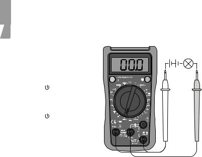
5.1 Voltage measurement
Check the battery by rotating the multifunction selector to a new measuring function. The battery symbol will appear if the battery starts to run low.
1. |
Connect the black test lead |
|
|
to COM and the red test lead |
~ |
|
to V. |
|
2. |
Set the function selector to |
|
|
V~ (200–600 V~) or |
|
|
V (2000 mV – 600 V) and |
|
|
the required measuring range |
|
|
for voltage measurement. |
|
3. |
Switch on the multimeter |
|
|
using [ ]. |
|
4. |
Connect the test leads across |
|
|
the voltage source to be |
|
|
measured. Read the value. |
|
5. |
Switch of the multimeter |
|
|
using [ ]. |
|
Note: If the incorrect polarity is connected when measuring DC voltages, the display will show - (minus) before the reading.
English
7
English
Note:
In each range, the meter has an input impedance of 10 MΩ except the mV range, which has an input impedance of 3000 MΩ. This can cause measurement errors in high impedance circuits. If the circuit impedance is less than or equal to 10 kΩ, the error is negligible (0.1 % or less).
5.2 DC current measurement
1.Connect the black test lead to COM and the red test lead to
mA (for 0–200 mA) or to 10A (for the range 200 mA – 10 A).
2. Set the multifunction selector to A 

 .
.
3. Switch on the multimeter using [ ].
4. Connect the test leads in series with the current source to be measured. Read the value.
5. Switch off the multimeter using [ ].
Warning!
Do not connect the leads in parallel with the voltage source when measuring current!
If in doubt about the correct range, start with the highest and work downwards.
When measuring high currents, the meter should only be connected briefly (less than 10 seconds for currents over 5 A). This is to prevent the shunt in the instrument from overheating.
The interval between two readings must be greater than 15 minutes.
8

5.3 Resistance measurement
1. Connect the black test lead to COM and the red test lead to Ω.
2. Set the multifunction selector to Ω and the required range for resistance measurement.
3. Switch on the multimeter using [ ].
4. Connect the test leads across the circuit to be tested.
Read the value.
5. Switch off the multimeter using [ ].
Warning: Ensure that the circuit to be tested is not “live” before taking any measurements.
In order to avoid the risk of personal injury, never measure components with a voltage higher than 60 V (DC) or 30 V (AC).
The test leads can add 0.1–0.2 Ω to the actual resistance measured. To obtain accurate readings of low-resistance components, short-circuit the input sockets beforehand, record the short-circuited reading and use it to remove the lead resistance error from the reading on the display.
If the short-circuited reading is higher than 0.5 Ω, check whether any connection/test lead is loose or damaged.
For high-resistance measurement (>1 MΩ), it is normal for the reading to take several seconds to stabilize.
For maximum accuracy, leads that are of the highest possible quality and as short as possible should be used.
English
9
English
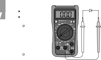
5.4 Diode testing
1. |
Connect the black test lead |
||||
|
to COM and the red test lead |
||||
|
to |
|
|
. |
|
|
|
|
|
||
2. |
Set the multifunction selector |
||||
|
to |
|
|
|
for measuring diode |
|
|
|
|
||
|
threshold value (V). |
||||
3. |
Switch on the multimeter |
||||
|
using [ ]. |
||||
4. |
Connect the black test lead to |
||||
|
the cathode and red test lead |
||||
|
to the anode of the diode to |
||||
|
be tested. Read the forward |
||||
|
voltage drop value from |
||||
|
the display. If “1” appears on |
||||
|
the display, reverse the polarity |
||||
|
of the diode. |
||||
5. |
Switch off the multimeter |
||||
|
using [ ]. |
||||
Warning!
Make sure that the circuit to be tested is not conducting any current before testing diodes.
Take extreme care when using this instrument on an inductive component such as a transformer, relay coils and the like, and make sure they have been discharged beforehand. High voltage may be induced at the measuring points if an open circuit occurs.
Note: A good diode should have a forward voltage drop of from 0.5 to 0.8 V. However, the reverse voltage drop reading can vary considerably depending on the resistance to other paths of conductance between the tips of the test leads.
10
5.5 Continuity measurement
1. Set the multifunction selector to 
 .
.
2.Connect the black test lead to COM and the red test lead to
Ω mA.
3. Switch on the multimeter using [ ].
4. Connect the ends of the test leads to the ends of the cables to be tested.
-- No break in the cable: The buzzer sounds continuously if
the resistance is <10 Ω. -- Break in the cable:
The buzzer does not sound if the resistance is >70 Ω.
5.Switch off the multimeter using [ ].
Warning!
Make sure that the circuit to be tested is not conducting any current before testing for continuity.
Take extreme care when using this instrument on an inductive component such as a transformer, relay coils and the like, and make sure they have been discharged beforehand. High voltage may be induced at the measuring points if an open circuit occurs.
To avoid shocks, you must be CAREFUL when working with voltages higher than 60 VDC or 30 VAC RMS. Voltages higher than this pose a risk of heavy electric shocks.
Note: The open-circuit voltage is around 2.3–2.5 V.
English
11

English
5.6 Taking temperatures
Note: Temperature measurement up to 230 °C with inbuilt temperature sensor. At higher temperatures, a different type of temperature sensor must be used.
1. Set the multifunction selector to °C.
2.Connect the multi-function socket to the multimeter and
the temperature sensor to the multi-function socket.
3. Switch on the multimeter using [ ].
4. Place the temperature sensor next to the place to be measured.
5. Read the value.
6. Switch off the multimeter using [ ].
5.7 Battery test
1. Set the multifunction selector to
1.5 V or 9 V.
2.Connect the black test lead to COM and the red test lead to
Ω mA.
3. Switch on the multimeter using [ ].
4. Connect the test leads to the battery to be tested.
5. Read off the battery’s voltage under load.
6. Switch off the multimeter using [ ].
Meter load during measurement: 1.5 V battery approx. 10 Ω.
9 V battery approx. 1 kΩ.
The battery measurement is intended for 1.5 V and 9 V batteries only. Batteries with a higher voltage can damage the meter.
12
5.8 Backlight
Press [ ☼ ] to switch the backlight on or off.
5.9 Sleep mode (automatic shut-off)
To preserve battery life, the meter has an auto shut-off feature. If the multifunction selector is not turned within 15 minutes, the meter turns itself off automatically.
If sleep mode has been activated, switch on the meter by pressing [ ] twice.
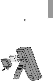
6. Changing the battery
Change the battery as soon as the battery symbol appears on the display.
Warning!
Make sure the test leads are disconnected from the circuit being tested before replacing the battery.
1.Turn the meter off and remove the test leads.
2.Unscrew the battery cover.
3.Remove the battery cover.
4. Remove the old battery and insert the new 9 V (6F22) battery, observing the correct polarity.
5. First, press the lower half of the battery cover/stand over the battery and then screw it in place.
English
13

English
7. Fuses
7.1 Checking the fuses
If the meter does not respond when measuring current, one of the fuses has probably blown. Checking the fuses:
1. Set the function knob to Ω range up to 200.
2. Switch on the multimeter using [ ].
3. Connect one of the test leads between the 10 A and Ω mA connections. It may take a little while for the value to stabilise. If the reading is 0.5 Ω or lower,
both fuses are whole. 4. Switch off the multimeter
using [ ].
7.2 Changing the fuses
The meter is protected by two fuses:
•1 × fuse 500 mA F (fast blow) 600 V (6.35 × 31.8 mm).
•1 × fuse 10 A F (fast blow) 600 V (6.35 × 31.8 mm).
1.Switch off the meter and remove the test leads.
2.Remove the three screws holding the casing together.
3.Remove the battery cover.
4.Remove the back of the meter to access the fuses.
5.The upper fuse is 10 A and the lower one 500 mA.
6.Replace the fuse with one of the identical type and specification.
7.Replace the battery holder.
8.Screw the casing together again.
10 A
500 mA
Warning!
Switch off the meter and remove the test leads from the circuit being tested before replacing the fuses.
14

8. Care and maintenance
Switch off the multimeter before cleaning.
Wipe the meter with a moist, soft cloth. Use a mild detergent and never use solvents or strong, abrasive cleaning agents for cleaning as these can damage the meter.
9. Disposal
This product should be disposed of in accordance with local regulations. If you are unsure what to do, contact your local authority.
10. General specifications
Polarity |
Automatic negative (-) polarity indication |
Zero adjustment |
Automatic |
Power supply |
1 × 6F22 battery (9 V) |
Overload protection |
1 × fuse 500 mA F (fast blow) 600 V (6.35 × 31.8 mm) |
|
1 × fuse 10 A F (fast blow) 600 V (6.35 × 31.8 mm) |
Measurement update |
2–3 times per second |
Measurement range |
Manual mode |
Battery warning |
The battery symbol is shown on the display |
Operating environment 0 to +40 °C at humidity ≤ 75 % (up to +30 °C) |
|
|
and ≤ 50 % (over +30 °C) |
Storage environment |
-10 to +50 °C at humidity ≤ 75 % (up to +30 °C) |
|
and ≤ 50 % (over +30 °C) |
Max. operating altitude |
Up to 2000 m above sea level |
Size (L × W × H) |
137 × 72 × 35 mm |
Weight (incl. batteries) |
approx. 200 g |
English
15

English
11. Electrical specification
11.1 Voltage measurement
Function |
Scale |
Resolution |
Accuracy |
Description |
|
|
|
(± a % reading, |
|
|
|
|
+ b number of |
|
|
|
|
digits) |
|
DC |
2000 mV |
1 mV |
± (0.5 % + 2) |
Input impedance |
|
20 V |
0.01V |
|
≥ 10 MΩ |
|
200 V |
0.1 V |
|
|
|
600 V |
1 V |
± (0.8 % + 2) |
|
AC |
200 V |
0.1 V |
± (1.2 % +3) |
Input impedance 4.5 MΩ |
|
600 V |
1 V |
|
Response: 45–400 Hz; |
|
|
|
|
Display: RMS of sine wave |
|
|
|
|
(mean value) |
11.2 DC measurement
Function |
Scale |
Resolution |
Accuracy |
Overload protection |
|
|
|
(± a % reading, |
|
|
|
|
+ b number of |
|
|
|
|
digits) |
|
DC Current |
2000 μA |
1 μA |
± (1 % + 2) |
mA: 0,5 A fuse |
|
20 mA |
0.01 mA |
|
10A:10 A fuse |
|
200 mA |
0.1 mA |
± (1.2 % + 2) |
|
|
10 A |
0.01 A |
± (2 % + 5) |
|
Warning! ≤ 5 A continuous measurement. ≥ 5 A each measurement max. 10 seconds, 15 minutes between each measurement.
11.3 Resistance measurement
Function |
Scale |
Resolution |
Accuracy |
|
|
|
(± a % reading, + b |
|
|
|
number of digits) |
Resistance |
200 Ω |
0.1 Ω |
± (0.8 % + 5) |
measurement |
2000 Ω |
1 Ω |
|
|
20 kΩ |
0.01 kΩ |
|
|
200 kΩ |
0.1 kΩ |
|
|
2000 kΩ |
1 kΩ |
|
|
20 MΩ |
0.01 MΩ |
± (1 % + 5) |
16
11.4 Temperature measurement
Function |
Measuring |
Resolution |
Accuracy |
h |
|
|
range |
|
(± a % reading, + b |
lis |
|
|
|
|
number of digits) |
ng |
|
|
|
|
|
E |
|
Measuring |
- 40 to - 20 °C |
1 °C |
-8 % + 5 °C |
||
|
|||||
Temperature |
-20–0 °C |
|
± 4 °C |
|
|
|
0–100 °C |
|
± (1.0 % + 3) |
|
|
|
100–1000 °C* |
|
± (2.5 % + 2) |
|
* Note! Temperature measurement up to 230°C with inbuilt temperature sensor. At higher temperatures, a different type of temperature sensor must be used.
11.5 Battery test
Function |
Measuring range |
Resolution |
Accuracy |
Battery test |
1.5 V |
10 mV |
± (1.0 % + 2) |
|
9 V |
10 mV |
|
Meter load during measurement: 1.5 V battery approx. 10 Ω. 9 V battery approx. 1 Ω.
11.6 Diode test and continuity test
Function |
|
Scale |
Resolution |
Remark |
|||
|
|
|
|
|
|
|
|
Measuring diodes |
|
|
|
|
|
1 mV |
Shows approx. value for |
|
|
|
|
|
|
|
forward voltage drop |
Continuity |
|
|
|
|
|
1 Ω |
The buzzer sounds < 70 Ω |
|
|
|
|
|
|
|
|
17

Svenska
Multimeter
Art.nr 36-5256 |
Modell UT132E |
Läs igenom hela bruksanvisningen före användning och spara den sedan för framtida bruk. Vi reserverar oss för ev. textoch bildfel samt ändringar av tekniska data.
Vid tekniska problem eller andra frågor, kontakta vår kundtjänst (se adressuppgifter på baksidan).
Innehållsförteckning |
|
|
1. |
Information om mätinstrument.......................................... |
19 |
1.1 |
Kategorisering.................................................................................................................... |
19 |
1.2 |
Föroreningsgrad................................................................................................................. |
19 |
2. |
Säkerhetsföreskrifter.......................................................... |
20 |
3. |
Förpackningen innehåller................................................... |
21 |
4. |
Funktioner........................................................................... |
21 |
5. |
Användning......................................................................... |
22 |
5.1 |
Spänningsmätning.............................................................................................................. |
22 |
5.2 |
Mätning av likström............................................................................................................ |
23 |
5.3 |
Resistansmätning............................................................................................................... |
24 |
5.4 |
Diodtest............................................................................................................................... |
25 |
5.5 |
Avbrottsmätning (kontinuitet)............................................................................................. |
26 |
5.6 |
Temperaturmätning............................................................................................................ |
27 |
5.7 |
Batteritest........................................................................................................................... |
27 |
5.8 |
Bakgrundsbelysning på displayen..................................................................................... |
28 |
5.9 |
Sleep (automatisk avstängning)......................................................................................... |
28 |
6. |
Batteribyte.......................................................................... |
28 |
7. |
Säkringar............................................................................. |
29 |
7.1 |
Kontroll av säkringarna...................................................................................................... |
29 |
7.2 |
Byte av säkringar................................................................................................................ |
29 |
8. |
Skötsel................................................................................ |
30 |
9. |
Avfallshantering.................................................................. |
30 |
10. Generell specifikation......................................................... |
30 |
|
11. Elektrisk specifikation........................................................ |
31 |
|
11.1 |
Spänningsmätning.............................................................................................................. |
31 |
11.2 |
Likströmsmätning............................................................................................................... |
31 |
11.3 |
Resistansmätning............................................................................................................... |
31 |
11.4 |
Temperaturmätning............................................................................................................ |
32 |
11.5 |
Batteritest........................................................................................................................... |
32 |
11.6 |
Diodtest och kontinuitetstest (avbrottsmätning)............................................................... |
32 |
18

1. Information om mätinstrument
Multimetern är konstruerad och testad enligt kraven för installationskategori II upp till 600 V nominell spänning och föroreningsgrad 2.
1.1 Kategorisering
Mätinstrument delas in i olika kategorier utifrån vilken elektrisk miljö de ska användas i och hur säkra/skyddande de är mot eventuella överspänningar.
Märkningen på mätinstrumentet ska visa vilken kategori det tillhör. Kategoriseringen avgör hur säkert instrumentet är mot eventuella överspänningar som kan utgöra fara för användaren.
I korthet kan kategoriseringen beskrivas så här:
Vid en plötslig överspänning på elnätet (en transient från ett blixtnedslag etc.) är faran störst vid exempelvis byggnadens inkommande matningsledning. Längre in i byggnaden ökar motståndet (impedansen) i ledningarna och anslutna apparater minskar och fördelar överspänningen. Mätinstrumentets kategori talar alltså om i vilken elektrisk miljö instrumentet är tänkt att användas.
Kategorierna som mätinstrumenten delas in i är:
•Kategori I: För mätning i elektronik och produkter som har inbyggt skydd mot överspänning.
•Kategori II: För mätning på enfasutrustning som strömförsörjs med byggnadens elsystem. Både stickproppsansluten och fast installerad.
•Kategori III: För mätning i byggnadens elsystem. Fast installerade ledningar, uttag, proppskåp och elcentraler. Trefasdistribution (alla matarkablar samt trefasutrustning, maskiner och apparater).
•Kategori IV: Trefas på primär nivå och alla ledare för utomhusbruk.
Den här multimetern tillhör installationskategori II och är avsedd för att mäta spänningar upp till 600 V i enfasprodukter. Multimetern ska inte användas för mätning
i trefasprodukter, trefasledningar eller elcentraler även om spänningen nominellt inte är högre än 600 V.
1.2 Föroreningsgrad
Multimetern är konstruerad för att kunna användas i miljöer med förekomst av föroreningar som inte är elektriskt ledande. Med undantag för att tillfällig ledningsförorening skulle kunna uppstå på grund av kondensering.
Exempel på miljöer med föroreningsgrad 2 är hemmiljö i torra utrymmen, kontor, teststationer eller labb. Kort sagt torra utrymmen som har normalt inomhusklimat.
Multimetern ska inte användas eller förvaras i utrymmen där den kan blir utsatt för elektriskt ledande föroreningar i någon form (fast, flytande eller gas.)
Svenska
19

Multimetern bör exempelvis inte utsättas för relativ luftfuktighet över 75 %, användas i ouppvärmda lokaler och får inte användas i våtutrymmen eller utomhus där den kan bli blöt.
Den är inte avsedd att användas med elektrisk utrustning som används i industri eller jordbruk.
|
2. Säkerhetsföreskrifter |
|
|
||
a |
• Multimetern är testad i enlighet med EMC-direktivet 2004/108/EC, |
|
sk |
lågspänningsdirektivet 2006/95/EG och uppfyller installationskategori |
|
en |
||
(överspänningskategori) II 600 V, föroreningsgrad 2 i enlighet med EN 61010– |
||
Sv |
1:2010 samt EN61010-031:2002/A1:2008. |
|
|
• Multimetern är avsedd för inomhusbruk, arbetstemperatur 0–40 °C. |
|
|
• Genom att följa alla säkerhetsföreskrifter och driftanvisningar kan du se till att |
|
|
multimetern används på ett säkert sätt. |
|
|
• Använd inte multimetern om instrumentet eller dess testkablar ser ut att vara |
|
|
skadade eller om du misstänker att multimetern inte fungerar som den ska. |
|
|
• Se till att dina fingrar är bakom testkablarnas fingerskydd när du använder |
|
|
testkablarna. |
|
|
• Kontrollera att strömmen är avstängd innan du gör några ingrepp i strömkretsen. |
|
|
Även små strömstyrkor kan vara farliga! |
|
|
• Mät inte högre spänning än 600 V DC eller 600 V AC RMS med multimetern. |
|
|
• För att undvika stötar ska du vara mycket FÖRSIKTIG när du arbetar med högre |
|
|
spänning än 60 V DC eller 30 V AC RMS. Högre spänning medför risk för kraftiga |
|
|
stötar. |
|
|
• Ställ in rätt mätområde med mätfunktionsväljaren innan mätningen påbörjas, |
|
|
mätområdet får inte ändras under pågående mätning. |
|
|
• Använd aldrig multimetern om batterifacket eller bakstycket är öppet. |
|
|
• För att undvika elektriska stötar eller skador på multimetern ska inte mätgränserna |
|
|
överskridas. Garantin gäller inte om multimetern används felaktigt. |
|
|
• Multimetern är skyddad med säkringar, men de skyddar inte mot alla typer av |
|
|
felanvändning. |
|
|
• Multimetern ska inte användas eller förvaras i miljöer som har hög temperatur/ |
|
|
luftfuktighet, inte heller i explosiva, brandfarliga omgivningar eller i närheten av |
|
|
starka magnetfält. |
|
|
• Byt ut batteriet genast när symbolen för batterivarning visas på displayen. |
|
|
Dåligt batteri kan medföra att fel mätvärden visas och kan därmed utgöra |
|
|
en säkerhetsrisk. |
|
|
• Multimetern eller dess tillbehör får inte demonteras eller modifieras på något sätt. |
|
|
• Ta ur batteriet om instrumentet inte ska användas under en längre tid. |
|
|
• Stäng av multimetern efter användning. |
|
|
• Om starka elektriska magnetfält finns i närheten av multimetern kan det leda till |
|
|
felvisning som upphör så snart störningen försvinner. |
20
3. Förpackningen innehåller
•Multimeter
•2 x testkablar
•Multisockel och temperaturgivare
•Bruksanvisning
4. Funktioner
1 |
2 |
5 |
6 |
Svenska
3 |
4 |
7 |
8 |
1.LCD-display
2.[ ] Strömbrytare (på/av)
3.[ ☼ ] Bakgrundsbelysning
4.Mätfunktionsväljare med 7 olika lägen
Anslutning för testkablar:
5.10 A (likströmsmätning upp till 10 A)
6.COM (gemensam återledare för den svarta testkabeln)
7.V (spänningsmätning)
8.Ω mA (likströmsmätning upp till 0,2 A, resistansmätning, diodtest, avbrottsmätning och temperaturmätning)
21

5. Användning
|
Varning! |
|
|
• Kontrollera alltid innan spänningsmätning att multimetern är inställd på rätt |
|
|
mätområde och inte på ström-, resistanseller diodmätning. Se till att du alltid |
|
|
använder rätt anslutning till testkablarna för den typ av mätning som ska göras |
|
|
med multimetern. |
|
|
• Använd yttersta försiktighet när du mäter spänning som överstiger 60 V, särskilt |
|
|
||
ka |
från mätobjekt med hög effekt. |
|
• Kontrollera att mätobjektet inte är strömförande innan du kopplar in testkablarna |
||
ns |
||
i serie med mätkretsen (t.ex. vid mätning av ström). |
||
e |
||
• Se till att den krets som ska testas inte är strömförande innan du mäter resistans |
||
v |
||
S |
||
eller summer/diodtest. |
||
|
||
|
• Se alltid till att rätt funktion och mätområde väljs. Om du är osäker på korrekt |
|
|
mätområde ska du börja med det högsta och arbeta dig nedåt. |
|
|
• Var ytterst försiktig när du använder multimetern på en induktiv komponent t.ex. |
|
|
transformator, reläspole eller liknande. Högspänning kan uppstå (induceras) vid |
|
|
mätpunkten när strömkretsen bryts. |
|
|
• Se till att testkablarna är i gott skick och att deras isolering inte är skadad. |
|
|
• Vid byte av säkring måste den nya vara av rätt typ och ha rätt värde. |
5.1 Spänningsmätning
Kontrollera batteriet genom att vrida mätfunktionsväljaren till en ny mätfunktion, batterisymbolen visas om batteriet börjar bli dåligt.
1. |
Koppla den svarta testkabeln |
|
|
|
till COM och den röda |
|
~ |
|
testkabeln till V. |
|
|
2. |
Ställ in mätfunktionsväljaren på |
||
|
V~ (200–600 V~) eller |
|
|
|
V (2000 mV – 600 V) och |
|
|
|
önskad mätskala för mätning |
|
|
|
av spänning. |
|
|
3. |
Slå på multimetern med [ ]. |
|
|
4. |
Koppla testkablarna till |
|
|
|
spänningskällan som ska |
|
|
|
mätas. Avläs mätvärdet. |
|
|
5. |
Stäng av multimetern med [ |
]. |
|
Obs! Om fel polaritet kopplats in vid likspänningsmätning visar displayen ett – (minus) före mätvärdet.
22

Obs!
I alla mätområden har multimetern en ingångsimpedans på 10 MΩ förutom mV som har en ingångsimpedans på 3000 MΩ. Detta kan leda till mätfel i kretsar med hög impedans. Om kretsens impedans är mindre eller lika med 10 kΩ, är mätfelet försumbart (0,1 % eller mindre).
5.2 Mätning av likström
1.Koppla den svarta testkabeln till COM och den röda
testkabeln till mA (för mätning mellan 0–200 mA) eller till
10 A (vid mätning mellan
200 mA och 10 A).
2. Ställ in mätfunktionsväljaren på A 

 .
.
3. Slå på multimetern med [ ].
4. Seriekoppla testkablarna mellan strömkälla och belastningen som ska mätas. Avläs mätvärdet.
5. Stäng av multimetern med [ ].
Varning!
Koppla inte in kablarna parallellt med spänningskällan vid strömmätning!
Om du är osäker på rätt mätområde ska du börja med det högsta och arbeta dig nedåt.
Vid mätning av hög strömstyrka får multimetern endast vara ansluten kort tid (mindre än 10 sekunder vid > 5 A). Detta för att inte överhetta shunten i multimetern.
Tiden mellan två mätningar måste vara mer än 15 minuter.
Svenska
23

Svenska
5.3 Resistansmätning
1. Koppla den svarta testkabeln till COM och den röda testkabeln till Ω.
2. Ställ in mätfunktionsväljaren på Ω och önskad mätskala för mätning av resistans.
3. Slå på multimetern med [ ].
4. Koppla testkablarna till den krets som ska mätas. Avläs mätvärdet.
5. Stäng av multimetern med [ ].
Varning: Kontrollera innan mätning att mätobjektet som ska testas är strömlöst.
För att undvika risk för personskada, mät inte komponenter som har högre spänning än 60 V (DC) eller 30 V (AC).
Testkablarna kan addera 0,1–0,2 Ω till det faktiska mätvärdet. För att göra noggranna mätningar på komponenter med låg resistans, kortslut ingångsanslutningarna, notera det kortslutna värdet och använd det för att räkna bort felmätningen i avläsningen
på displayen.
Om det kortslutna värdet är högre än 0,5 Ω så kontrollera om någon anslutning/ testkabel är glapp eller skadad.
Vid mätning av hög resistans (>1 M Ω) är det normalt att det tar några sekunder innan visningen av mätresultatet stabiliseras.
För bästa noggrannhet så bör, korta och högkvalitativa testkablar som möjligt användas.
24
 Loading...