


COMPACT PARTS BENDERS
MODEL NO: CCB1B & CCB2B
PART NO: 7630083 & 7630084
OPERATION
INSTRUCTIONS
ORIGINAL INSTRUCTIONS GC0221 rev -2

INTRODUCTION
Thank you for purchasing this CLARKE product. The compact metal parts
bender allows you to economically make a variety of bends in flat, square or
solid round stock. These instructions provide basic information on using the
bender, plus step-by-step examples of how to bend stock to make several
common products. We urge you to read the complete Operation section
before trying to use the bender.
Before attempting to use this product, please read this manual thoroughly and
follow the instructions carefully. In doing so you will ensure the safety of yourself
and that of others around you and you can look forward to your purchase
giving you long and satisfactory service.
GUARANTEE
This product is guaranteed against faulty manufacture for a period of 12
months from the date of purchase. Please keep your receipt which will be
required as proof of purchase.
This guarantee is invalid if the product is found to have been abused or
tampered with in any way, or not used for the purpose for which it was
intended.
Faulty goods should be returned to their place of purchase, no product can
be returned to us without prior permission.
This guarantee does not effect your statutory rights.
SAFETY PRECAUTIONS
WARNING: THE USER MUST FOLLOW ALL INSTRUCTIONS WITHIN THIS
INSTRUCTION BOOKLET
To protect against serious injury, use common sense and observe the following
precautions when using this product. Clarke International is not responsible for
misuse of the equipment.
• ALWAYS secure the metal bender to the floor or bench before use.
• ALWAYS study these instructions before operating and pay close
attention to all warnings.
• ALWAYS keep the work area free of obstructions.
2

• ALWAYS wear safety goggles when bending parts and when
grinding or sanding them.
• ALWAYS be sure that enough material extends beyond the stop
block and forming die when making bends, to be sure the material
does not come free and allow the handle to release suddenly.
• ALWAYS insert the hinge pins fully before making bends.
• NEVER try to bend material other than hot-rolled mild steel.
• NEVER try to bend flat material larger than 5 16 x 2 in or square or
solid round material larger than 5 8 in. (EXCEPTION: Rebar that is 1/2in. diameter may be bent around the 3” die only).
• NEVER bend round stock when using the sharp-angle-bend
attachment. Use only flat, hot-rolled, mild steel up to 3/16 x 2” or 1/4
x 1-1/4” with this attachment.
• NEVER try to bend material that is more than 1/ 4” thick around the
centre pin (instead, use the 1” die on the pin).
• NEVER modify the metal bender or use a handle extension arm other
than the one provided.
INDEX
Assembly 4
Basic Operations 5
Using the Stop Block 7
Using the Sharp-Angle-Bend Attachment 9
Examples
Bending Handles 10
Bending Tube Clamps 12
Bending Anchor Bolt
Bending Letters for Signs 19
Parts List & Diagram 46
s and U-Bolts 15
3

ASSEMBLY
1. To attach the ring assembly to the
stand (refer to the illustration
posite):
op
a. Attach the loop end of the ring
a
ssembly to the stand. Use the long bolt,
flat washer, thick spacer (inside the
loop), thin spacer, lock washer, and lock
nut.
b.Attach the ring end to the stand with
the two flat-head bolts, using thin
spacers, flat washer, lock washers, and
lock nuts.
2. Insert the loop end of the handle
inside the loop
and secure it by inserting one of the
two longer hitch pins.
3. Remove the 'R' clip from the handle
pin then remove the pin from the
handle. Pull out the extension arm,
install the pin in the outer hole, and
reinstall the 'R' clip.
4. Set the bender in the position where
you intend it to be used. Rotate the
handle as far as it will go in both directions, to be sure there will be no
obstructions when bending.
of the ring assembly,
5. Attach the bender’s base securely to the floor.
4

BASIC OPERATION
Most of this manual is devoted to showing you how to create basic shapes.
Other than these specific instructions, setting up the bender to form your
particular shape will involve a certain amount of trial-and-error.
You will notice some differences in operation depending on whether you are
forming the piece around a die, or whether you are making a sharp-angle
bend in the piece. However, in general you will:
1. Determine the appropriate material and size for the part(s) to be made.
2. Determine the appropriate dies to install on the centre pin and/or the pin
installed in the handle, and determine the appropriate hole for attaching
the handle to the ring assembly’s loop.
3. Install the stop block or the sharp-angle-bend attachment, as appropriate.
Install the block support. If the stop block is used, orient it properly. Refer to
pages 4 and 5 for more information on the stop block and the sharp-anglebend attachment.
4. Insert the blank stock into the bender, and position it properly for the first
bend.
5. Make the first bend. Re-check the angle and location before continuing.
6. Make any additional bends in the same way. In some cases, you may have
to remove the piece from the bender and turn it end-for-end or upsidedown.
HOLE IDENTIFICATION
In the examples shown in this manual,
the holes in the loop and those in the
handle are identified by a number.
Refer to the illustration at right.
MEASURING BEND ANGLES
When accuracy is required, you will
need a suitable device for measuring
the bend angles.
FIXED AND ADJUSTABLE STOPS
If you are making multiple parts with
the same bend angle, using the
same setup (dies and hole locations),
the operation will be speeded up by
installing either the fixed or adjustable stop in the appropriate hole in the ring
assembly.
5

After determining the handle
rotation, insert the fixed stop into the
next open hole and use as a guide
for bending additional parts.
When greater precision is required,
attach the adjustable stop as
accurately as you can at the limit of
handle rotation. Make a test part with
scrap material, and reposition the
adjustable stop as necessary. Tighten
bolt and nut securely before bending
production parts.
NOTE: If precise dimension are
required, start by making a
test part using scrap
material of the same thickness. Readjust the setup as necessary.
NOTE: Once you determine the dimensions, die size(s), holes, and
bending sequence for a part, write down the information for
future reference.
6

USING THE STOP BLOCK
IMPORTANT: Read page 4 before you proceed to this section.
THE PURPOSE OF THE STOP BLOCK
The stop block prevents the material
from rotating while a forming die in the
handle bends the material around
either the centre pin or another die that
has been installed on the centre pin.
When you are bending material, the
stop block will be located (using a hitch
pin) at one of the five large holes in the
middle of the ring assembly’s loop. (The
large hole at the open end of the loop
is for the centre pin.) You will have to
determine by trial which hole you will
use, depending on the thickness of the
material being bent, the size of the
centre-pin die, and the orientation of
the stop block.
POSITIONING THE STOP BLOCK
The stop block can be placed in several
positions by rotating it on the hinge pin
or by turning it upside down and
rotating it on the pin. However, only four
of the possible positions are used when
bending. Throughout this manual, those
four positions are identified by a
number (refer to the illustration at right).
CAUTION: ALWAYS POSITION THE STOP
BLOCK OFF-CENTRE TO THE RIGHT—NO
MATTER WHICH FACE IS USED AGAINST THE
MATERIAL. IF POSITIONED OFF-CENTRE TO
THE LEFT, THE BLOCK WILL TURN AND THE
MATERIAL WILL SLIP IN THE BENDER.
To position the stop block (that is, to
select the proper orientation and the
proper hole in the loop):
1. Connect the handle to the centre
pin of the loop, with the appropriate
die installed on the centre pin.
7

2. Install the appropriate die at the appropriate hole in the handle.
3. Inset a piece of the material to be formed. With the handle all the way
back (anticlockwise), install the stop block in the orientation that places it
as close to the centre pin as possible.
IMPORTANT: Always use the loop hole that places the stop block as close to
the centre pin or die as possible, while leaving space for the material to be
inserted.
If there is too much space between the stop block and the centre pin or die,
turn the block to a different orientation or move the block one hole closer to
the centre.
POSITIONING THE BLOCK SUPPORT
The block support must be located under the stop block as shown, to keep the
block centered vertically in the loop.
Install the support in the appropriate loop hole where it will support the stop
block but not interfere with inserting the hitch pin all the way through the
block hole and the lower hole in the loop.
CLAMPING
If the stop block is positioned
correctly, the material will normally
not have to be clamped in the
bender. However, when you are
making special bends or need
precise dimensions, it is helpful to
clamp the material against the stop
block using a vice-grip pliers as
shown at right.
8
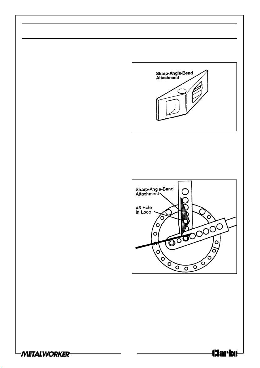
USING THE SHARP-ANGLE-BEND ATTACHMENT
PURPOSE OF THE ATTACHMENT
The sharp-angle-bend attachment is
used instead of the stop block when
you make a right-angle bend or
other sharp bend in flat material.
POSITIONING THE ATTACHMENT
In contrast to the stop block, the
sharp-angle bend attachment has
only one correct orientation—as
shown at right, and with the hinge pin
in the #2 hole in the loop.
POSITIONING THE BLOCK SUPPORT
The block support must be located under the sharp-angle-bend attachments,
to keep the attachment centered vertically in the loop. (Compare the
illustration on page 6 with the stop block.)
Install the support in the #3 loop hole,
so it will support the attachment but
not interfere with inserting the hitch
pin all the way through the
attachment’s hole and the lower
hole in the loop.
CLAMPING
The material should not need to be
clamped when using the sharpangle-bend attachment.
BENDING THE MATERIAL
Make thin chalk marks on the flat
material to show where you want to make the bends. For an example, see
page 10.
Insert the material into the bender so that half the width of the chalk mark
shows and the other half is covered by the bending edge of the attachment.
If you are making two right-angle bends on the same side of the material,
space their chalk marks about 1/8” further apart than the desired inside
dimension after the bend.
9

EXAMPLE: BENDING HANDLES
HANDLES FROM ROUND STOCK
To make a typical handle, using a 9in. length of 3/8in. round stock and two
pieces of flat stock:
NOTE: To make other sizes of handles, experiment to find the
appropriate die sizes and stop block orientation.
1. With a long hinge pin, attach the handle and ring loops at their centre-pin
holes. Install a 1in. die on the centre pin. With the short hinge pin, install a 2
in. die in the handle (#2 hole).
2. With a long hinge pin, install the stop block (oriented as in A).
3. Insert the round stock into the Bender so that it extends 2” beyond the
centre-pin die (see B), and make the first bend to 90°.
4. Turn the part end-for-end, position it as in C, and make the second 90°
bend. Remove the stock from the bender.
5. Drill 5/8”holes in the flat stock & insert the handle halfway through the holes
Always drill the holes the same size as the diameter of the handle stock.
6. Weld the flat stock pieces in place from the back side. If any weld material
extends below the surface of the flat plate, grind it flush.
10

HANDLES FROM FLAT STOCK
To make a typical handle, using a 9” length of 3/16” x 1” hot-rolled flat stock:
NOTE: To make other sizes of handles, experiment to find the
appropriate bend locations.
1. Install the sharp-angle-bend
attachment.
2. Place chalk marks on the material
as shown under “Bend
Sequence.” the #1 and #2 marks
are on one face of the material
and the #3 and #4 marks are on
the opposite face.
3. Insert the flat stock into the bender to the #1 mark as in A) and make a 90°
bend. Check the angle before continuing.
4. Set the adjustable stop so each bend will be 90°.
5. Turn the stock end-for-end. Insert it to the #2 mark
bend.
6. Turn the stock over front-to-back.
a 90° bend.
7. Turn the stock end-for-end. Insert it to the #4 mark (as in
bend.
8. Grind and sand all sharp corners.
Insert it to the #3 mark (as in C) and make
(as in B) and make a 90°
D) and make a 90°
11

EXAMPLE: BENDING TUBE CLAMPS
SINGLE-TUBE CLAMP
To make a 1” I.D. tube clamp (for
clamping 1” O.D. tubing), using a 4½”
length of 3/16” x 1” hot-rolled flat
stock:
NOTE: To make other sizes of
clamps, experiment to find
the appropriate die sizes
and stop block orientation.
1. With a long hinge pin, attach the
handle and ring loops at their
centre-pin holes. Install a 1” die on
the centre pin.
2. With the short hinge pin, install a
1½-in. die in the handle (#2 hole).
3. With a long hinge pin, install the
stop block (oriented as in A
below).
4. Insert the flat stock into the bender so that it extends 1½-in. beyond the
centre-pin die (as in B below).
5. Clamp the stock against the stop block using a vice-grip pliers, to prevent
the stock from slipping.
6. Make the first bend by pulling the handle around until the handle die runs
off the end of the piece.
7. Remove the stop block and the two dies. Change the handle connection,
and install the sharp-angle-bend attachment (as in C below).
8. Insert the stop pin into the 6th hole of the ring (counting clockwise from the
closed end of the loop).
12
9. Make the second bend by pulling the handle until it is about 1/8” from the
stop pin.
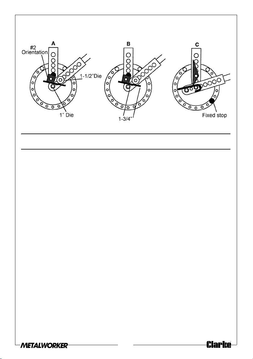
EXAMPLE: BENDING DOUBLE TUBE CLAMPS
DOUBLE-TUBE CLAMP
To make a 1” I.D. tube clamp (for clamping two lengths of 1” O.D. tubing),
using a 4½” length of 3/ 16” x 1” hot-rolled flat stock:
NOTE: To make other sizes of clamps, experiment to find the
appropriate die sizes and stop block orientation.
1. With a long hinge pin, attach the handle and ring loops at their centre-pin
hole
s. Install a 1” die on the centre pin.
2. With the short hinge pin, install a 1½” die in the handle #2 hole).
3. With a long hinge pin, install the
4. Insert the flat stock into the bender so th
centre-pin die (as in B).
stop block (oriented as in A).
at it extends 1-3/4” beyond the
13
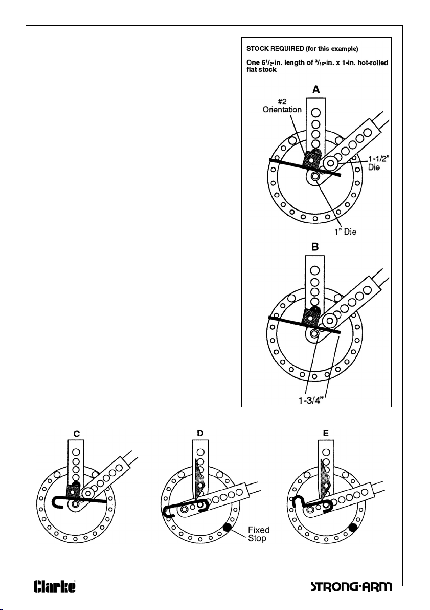
5. Make the first bend by pulling the
handle around until the handle die runs
off the end of the piece.
6. Reverse the part end-for-end. Insert it
into the Bender so that it extends 1-3/4”
beyond the centre-pin die (as in C).
7. Make the second bend by pulling the
handle around until the handle die runs
off the end of the piece.
8. Remove the stop block,
sharp-angle-bend attachment.
9. You will have to temporarily remove the
centre pin to insert the piece into the
bender. Slide the piece as far left as
possible, against the centre pin (as in
D).
10. Make the third bend by pulling the
handle until it is about 1/8” from the
stop pin.
11. Reverse the part end-for-end. Slide the
piece as far left as possible, against the
centre pin (as in E). You will again have
to temporarily remove the centre pin to
insert the piece into the bender.
12. Make the fourth bend by pulling the
handle until it is about 1/8” from the
fixed stop.
and install the
14

BENDING ANCHOR BOLTS AND U-BOLTS
ANCHOR BOLTS
To make a 10” long anchor bolt
shown, from a 12¼” blank:
NOTE: To make another length
bolt, just use a shorter or
longer blank, or, change the
dimension given in Step 3
below (being sure that
enough material is caught
by the block).
1. With a long hinge pin, attach the
handle and ring loops at their
centre pin holes. Install a 1” die on
the centre pen.
2. With the short hinge pin, install a
2” die in the handle #2 hole).
3. With a long hinge pin, install the
stop block. Orientate the block appropriately for the diameter of the u-bolt
blank:
#2 orientation for 3/8” or ½” bolts;
#4 orientation for 5/8” bolts
4. Insert the bolt blank into the bender so that the un-threaded end extends
beyond the stop block:
• 1/2” for 3/8” bolts;
• 5/8” for ½” bolts;
• 3/4” for 5/8” bolts.
5. Pull the handle around until the bolt shaft is 90° from the anchor.
15

U-BOLTS
The tables on pages 18 and 19 show the appropriate setup for making U-bolts
in typical finished lengths and bend radiuses, from common diameters of
round stock.
The illustration below shows the setup for making a U-bolt that is 3½” long and
2” I.D., using 5/8” diameter stock. For other sizes, adjust the die sizes, stop block
orientation, etc., as shown in the tables.
LENGTH
For longer U-bolts, add twice the additional length desired to the “blank
length” indicated (for example, to make a U-bolt that is 1” longer, add 2” to
the blank length).
BEND RADIUS
Eight bend radiuses are possible—by selecting from the seven forming dies, or
by using centre pin without a die. However to avoid bending the centre pin,
always use a forming die with round stock larger than 3/8” diameter.
NOTES
• Because blank stock may vary slightly in content or size, we
recommend making a test bend using unthreaded stock before you
make a quantity of U-bolts.
• Keep a record of die sizes, die positions, and other measurements for
future reference.
16

BENDING U-BOLTS FROM 1/4” ROUND STOCK
FINISHED SIZE SETUP FOR BENDING
Length I.D. Blank
Length
2” 1” 5” 1 2 Flush 1” 2” 2
2¼” 1¼” 5¼” 1 2 ¼” 1¼” 2” 2
2½” 1½” 6⅜” 1 1 ⅜ 1½” 2” 2
3” 1¾” 7½” 2 4 ¼” 1¼” 2” 2
3½”2”8⅝” 2 4 ⅞ 2” 1¾” 2
Loop
Hole
No
Stop
Block Ori-
entation
17
Stop
Block
meas’t
Centre
Pin Die
Handle
Die
Handle
Hole No

BENDING U-BOLTS FROM 1/4” ROUND STOCK
FINISHED SIZE SETUP FOR BENDING
Length I.D. Blank
Length
2½” 1¼” 6¼” 1 1 5/16” 1¼” 2” 2
3” 1½” 7⅜” 2 4 ¼” 1½” 2” 2
3” 1¾” 7⅝” 2 4 ⅜” 1¾” 2” 2
3½” 2” 8¾” 2 4 15/16” 2” 2” 2
Loop
Hole
No
Stop
Block Ori-
entation
Stop
Block
meas’t
Centre
Pin Die
Handle
Die
BENDING U-BOLTS FROM 3/8” ROUND STOCK
FINISHED SIZE SETUP FOR BENDING
Length I.D. Blank
Length
2½” 1¼” 6-½” 1 1 ⅝” 1¼” 2” 2
3” 1½” 7-½” 2 4 7/16” 1½” 3” 2
3” 1¾” 7-¾” 2 4 9/16” 1¾” 3” 2
3” 2” 8” 2 3 ⅛” 2” 2” 2
Loop
Hole
No
Stop
Block Ori-
entation
Stop
Block
meas’t
Centre
Pin Die
Handle
Die
BENDING U-BOLTS FROM 1/2” ROUND STOCK
Handle
Hole No
Handle
Hole No
FINISHED SIZE SETUP FOR BENDING
Length I.D. Blank
Length
2¾” 1½” 7¼” 2 4 7/16” 1½” 3” 3
3” 1¾” 8” 2 4 5/16” 1¾” 2” 3
3¼”2”8¾” 2 3 ¾” 2” 2½” 3
4” 2½” 10⅛” 2 2 1” 2½” 2” 3
4½” 3” 11⅝” 3 4 1” 3” 2” 3
Loop
Hole
No
Stop
Block Ori-
entation
18
Stop
Block
meas’t
Centre
Pin Die
Handle
Die
Handle
Hole No

BENDING U-BOLTS FROM 5/8” ROUND STOCK
FINISHED SIZE SETUP FOR BENDING
Length I.D. Blank
Length
3½” 2” 9¾” 2 2 1” 2” 3” 3
2½ 2½” 11½” 2 1 1⅝” 2½” 2” 3
5” 3” 12¾” 3 4 1⅞” 3” 2” 3
Loop
Hole
No
Stop
Block Ori-
entation
Stop
Block
meas’t
Centre
Pin Die
Handle
Die
BENDING LETTERS FOR SIGNS
Handle
Hole No
The following pages show how to make all 26 letters of the alphabet in a
typical style. Using the procedure that is shown on these pages results in letters
(from 3/16” flat stock) which are:
•6” high
•2” wide (deep)
NOTES
•Use only hot-rolled mild steel for forming the letters.
• Follow the bending steps exactly, and in the sequence given. This is
especially important for the letter “S”, which is the most difficult to
form.
19

• To avoid wasting material, practice some of the letters using 316”
stock that is only 1/2” wide before you attempt the finished version.
• If you have two or more identical letters, make all of them before
proceeding to a different letter.
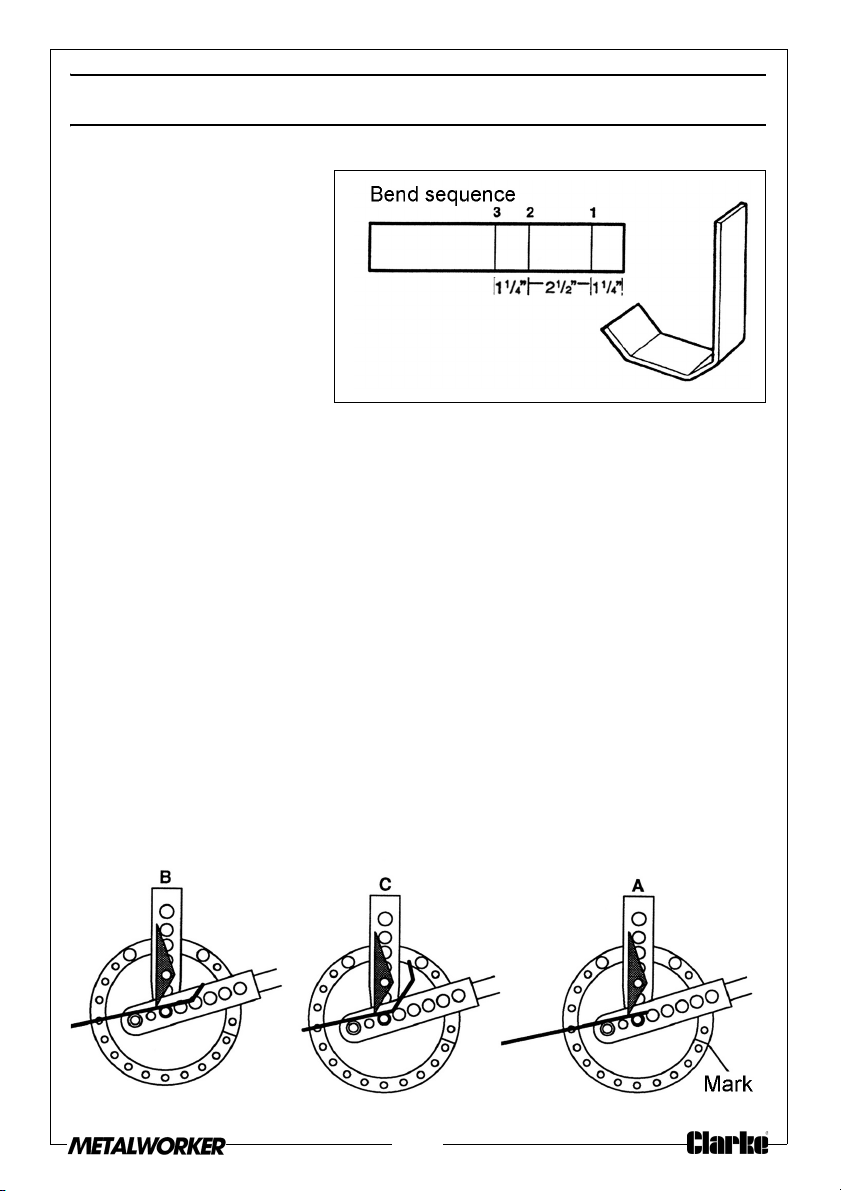
LETTER A
STOCK REQUIRED
• 3/16” stock; 2” max. width
• One 14” blank
• One 3-1/2” blank
SETUP
Make chalk marks on the 14” blank as shown on the “Bend Sequence.”
BEND NO. 1
Insert the stock into the Bender to the #1 chalk mark (as in A), and bend it to
76°. Re-check the angle before you go on to the second bend.
20

BEND NO. 2
Slide the stock to the #2 chalk mark (as in B), and bend it to 76°. Re-check the
angle.
To remove the part from the Bender, remove the pin that holds the sharpangle-bend attachment.
FINISHING
Tack-weld the 3-1/2”. insert piece between the legs of the “A,” parallel to the
top edge. Grind and sand all sharp corners.
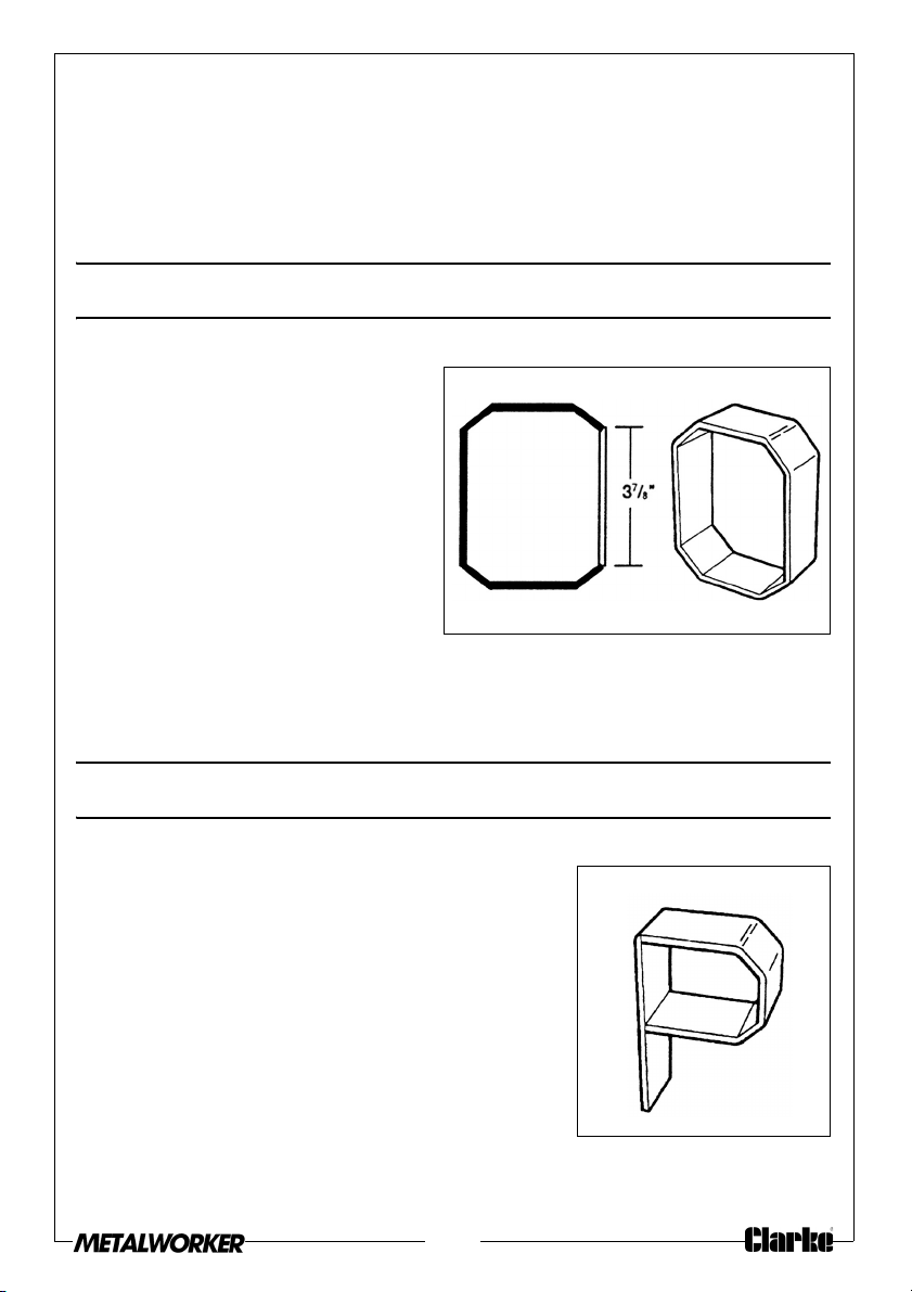
LETTER B
STOCK REQUIRED
• 3/16” stock; 2” max.
Width
SETUP
Make chalk marks on the
two 8-7/8” blanks as shown
on the “Bend Sequence.”
BEND NO. 1
Insert one of the blanks into the Bender to the #1 chalk mark (as in A), and
bend it to 45°. Re-check the angle before you go on to the second bend.
Chalk-mark the ring, or set a stop, for ease of repeating the 45° bend.
BEND NO. 2
Slide the stock to the #2 chalk mark (as in B), and bend it to 45°. Re-check the
angle.
BEND NO. 3
Reverse the stock end-for-end. Slide it to the #3 chalk mark (as in C), and bend
it to 45°. Re-check the angle.
BEND NO. 4
Again reverse the stock end-for-end. Move it to the #4 chalk mark (as in D),
and bend it to 45°. Re-check the angle.
To remove the part from the Bender, remove the pin that holds the sharpangle-bend attachment.
21

FINISHING
Tack-weld the two loops together. Tack-weld the 6 in. piece to form the back
of the letter “B”. Grind and sand all sharp corners.
LETTER C
STOCK REQUIRED
• 3/16” stock; 2” max. Width (1x 14-in blank)
SETUP
Make chalk marks on the 14” blank as shown on the “Bend Sequence.”
22

BEND NO. 1
Insert the stock into the Bender to the #1 chalk mark (as in A), and bend it to
45°. Re-check the angle before you go on to the second bend.
BEND NO. 2
Slide the stock to the #2 chalk mark (as in B), and bend it to 45°. Re-check the
angle.
BEND NO. 3
Slide the stock to the #3 chalk mark (as in C), and bend it to 45°. Re-check the
angle.
FINISHING
Reverse the stock end-for-end. Slide it to the #4 chalk mark (as in D), and bend
it to 45°. Re-check the angle.
BEND NO. 4
Slide the stock to the #5 chalk mark (as in E), and bend it to 45°. Re-check the
angle.
BEND NO. 65
Slide the stock to the #6 chalk mark (as in F), and bend it to 45°. Re-check the
angle.
23

To remove the part from the bender, remove the pin that holds the sharp-
angle-bend attachment.
FINISHING
Grind and sand all sharp corners.
24

LETTER D
STOCK REQUIRED
• 3/16” stock; 2” max. width
• 1x 12-1/2in blank
• 1 x 6 in blank
SETUP
Make chalk marks on the two 12-7/8”
blank as shown on the “Bend
Sequence.”
BEND NO. 1
Insert the blank into the Bender to the
#1 chalk mark (as in A), and bend it
to 45°. Re-check the angle before
you go on to the second bend.
Chalk-mark the ring, or set a stop, for
ease of repeating the 45° bend.
BEND NO. 2
Slide the stock to the #2 chalk mark
(as in B), and bend it to 45°. Re-check
the angle.
Remove the blank from the Bender.
Re-check that the bend leg is at 90°
to the front of the “D”.
25

BEND NO. 3
Reverse the stock end-for-end. Slide it to the #3 chalk mark (as in C), and bend
it to 45°. Re-check the angle.
BEND NO. 4
Slide the stock to the #4 chalk mark (as in D), and bend it to 45°.
Re-check the angle. Re-check that the two legs are parallel.
To remove the part from the Bender, remove the pin that holds the sharpangle-bend attachment.
FINISHING
Tack-weld the 6 in. piece to form the back of the letter “D”. Grind and sand all
sharp corners.
26

LETTER E
STOCK REQUIRED
• 3/16” stock; 2” max. width
• 1x 14-9/16in blank
• 1 x 2-1/2 in blank
SETUP
Make chalk marks on the 14-9/16” blank as shown on the “Bend Sequence.”
BEND NO. 1
Insert the blank into the bender to the #1 chalk mark (as in A), and bend it to
45°. Re-check the angle before you go on to the second bend.
27

BEND NO. 2
Slide the stock to the #2 chalk mark (as in B), and bend it to 90°. Re-check the
angle.
BEND NO. 3
Reverse the stock end-for-end. Slide it to the #3 chalk mark (as in C), and bend
it to 45°. Re-check the angle.
BEND NO. 4
Slide the stock to the #4 chalk mark (as in D), and bend it to 90°. Re-check the
angle and that the top and bottom of the E are parallel.
To remove the part from the bender, remove the pin that holds the sharpangle-bend attachment.
FINISHING
Tack-weld the 3-1/2 in insert piece in piece between the legs of the “A”,
parallel to the top edge. Grind and sand all sharp corners.
LETTER F
STOCK REQUIRED
• 3/16” stock; 2” max. width
• 1x 10⁻³/8in blank
• 1 x 2-1/2 in blank
SETUP
Make a letter “L” as shown on page 33.
FINISHING
Position the 2-1/2” piece as shown and tack weld it.
Grind and sand all sharp corners.
28

LETTER G
STOCK REQUIRED
• 3/16” stock; 2” max. width
• 1x 14in blank
• 1 x 3 in blank
SETUP
Make a letter “C” as shown on
pages 22-25.
BEND
Insert the 3” blank into the bender to the chalk mark and bend it to 90°. Recheck the angle.
To remove the part from the bender, remove the pin that holds the sharpangle-bend attachment.
FINISHING
Position the 3” piece as shown and tack-weld it. Grind and sand all sharp
corners.
LETTER H
STOCK REQUIRED
• 3/16” stock; 2” max. width
• 2 x 6in blank
• 1 x 3-1/4 in blank
SETUP
None
FINISHING
Tack-weld the pieces together as
shown.
Re-check that the pieces are at 90° to each other. Grind and sand all sharp
corners.
29

LETTER I
STOCK REQUIRED
• 3/16” stock; 2”
max. width
• 2 x 5in blank
• 1 x 5-5/8 in blank
SETUP
Make chalk marks on
the 5” blanks as shown
on the “Bend
Sequence.”
BEND NO. 1
Insert the blank into
the Bender to the #1
chalk mark, and bend it to 45°. Re-check the angle.
Chalk mark the ring, or set a stop, for ease of repeating the 45° bend.
BEND NO. 2
Reverse the stock end-for-end. Slide it to the #2 chalk mark, and bend it to 45°.
Re-check the angle.
To remove the part from the Bender, remove the pin that holds the sharpangle-bend attachment.
FINISHING
Position the 5-5/8” piece between the bent pieces as shown and tack-weld it.
Re-check that the parts are 90°.
Grind and sand all sharp corners.
30
LETTER J
STOCK REQUIRED
• 3/16” stock; 2” max.
width
• 1 x 10in blank
SETUP
Make chalk marks on the
blanks as shown on the
“Bend Sequence.”
BEND NO. 1
Insert the blank into the bender to the #1 chalk mark, (as in A), and bend it to
45°. Re-check the angle before you go on to the second bend.
Chalk mark the ring, or set a stop, for ease of repeating the 45° bend.
BEND NO. 2
Slide the stock to the #2 chalk mark (as in B), and bend it to 45°. Re-check the
angle.
BEND NO. 3
Slide the stock to the #3 chalk mark (as in C), and bend it to 45°. Re-check the
angle.
To remove the part from the bender, remove the pin that holds the sharpangle-bend attachment.
FINISHING
Grind and sand all sharp corners.
31

LETTER K
STOCK REQUIRED
• 3/16” stock; 2” max.
width
• 1 x 7in blank
• 1 x 6in blank
• 1 x 2-1/2 in blank
SETUP
Make chalk marks on the 7”
blanks as shown on the
“Bend Sequence.”
BEND
Insert the blank into the
Bender to the chalk mark,
and bend until it measures 6
in. as shown.
FINISHING
Tack-weld the pieces together as shown.
Re-check that the outer tips of the bent piece are equal distances from the
straight piece. Grind and sand all sharp corners.
LETTER L
STOCK REQUIRED
• 3/16” stock; 2” max. width
• 1 x 10⁻³/8in blank
SETUP
Make chalk marks on the blanks as shown on the “Bend Sequence.”
BEND NO. 1
Insert the blank into the Bender to the #1 chalk mark, and bend it to 45°. Recheck the angle.
32

BEND NO. 2
Slide the stock to the #2 chalk mark, and bend to 90°. Re-check the angle.
To remove the part from the bender, remove the pin that holds the sharp-
angle-bend attachment.
FINISHING
Grind and sand all sharp corners.
LETTER M
STOCK REQUIRED:
• 3/16” STOCK; 2” max width
• 2 X 13-1/2”” Blanks
SETUP
Make two letter “v”s as shown on
page 42.
33

FINISHING
Turn the “V”s upside down and tack weld them together as shown. Check
that the three bottom tips are aligned.
Grind and sand all sharp corners.
LETTER N
STOCK REQUIRED:
• 3/16” STOCK; 2” max width
• 1 X 8-1/16” blank
• 2 x 6 in blanks
SETUP
Make chalk marks on the 8-1/16” blanks as shown on the “Bend Sequence.”
BEND NO. 1
Insert the blank into the Bender to the #1 chalk mark, (as in A), and bend it to
73°. Re-check the angle.
BEND NO. 2
Reverse the stock end-for-end. Slide it to the #2 chalk mark, and bend it to 73°.
Re-check the angle.
34
To remove the part from the bender, remove the pin that holds the sharpangle-bend attachment.
FINISHING
Tack-weld the pieces together. Re-check that the straight legs are parallel.
Grind and sand all sharp corners.
LETTER O
STOCK REQUIRED:
• 3/16” STOCK; 2” MAX WIDTH
• 1 X 14” Blank
• 1 x 3-7/8” Blank
SETUP
Make a letter “C” from the 14”
blank as shown on page 17
FINISHING
Tack-weld the two pieces together as shown. Grind and sand all sharp
corners.
.
LETTER P
STOCK REQUIRED:
• 3/16” STOCK; 2” MAX WIDTH
• 1 X 8-7/8” Blank
• 1 x 6” Blank
SETUP
Make part of a letter “B” (page16)—the straight
piece and one loop.
FINISHING
Tack-weld the pieces together. Grind and sand all sharp corners
35

LETTER Q
STOCK REQUIRED:
• 3/16” STOCK; 2” MAX WIDTH
• 1 X 14” Blank
• 1 x 3-7/8” Blank
• 1 x 2” Blank
• 1 x 3/4” Blank
SETUP
Make a letter “O” (above).
FINISHING
Tack-weld the short pieces to the “O” as shown above. Grind and sand all
sharp corners.
LETTER R
STOCK REQUIRED:
• 3/16” STOCK; 2” MAX WIDTH
• 1 X 8-7/8” Blank
• 1 x 6” Blank
• 1 x 3-1/8” Blank
SETUP
Make part of a letter “P” (page 26).
FINISHING
Tack-weld the 3-1/8” piece to the “P” as shown.
Grind and sand all sharp corners.
36

LETTER S
STOCK REQUIRED:
• 3/16” STOCK; 2” MAX WIDTH
• 1 X 16-1/2” Blank
SETUP
Make chalk marks on the blank as shown on the “Bend Sequence.” Note that
the five chalk marks on one end of the blank must be on the opposite face
from the five marks on the other end.
BEND NO. 1
Insert the blank into the Bender to
the #1 chalk mark (as in A), and
bend it to 45°. Re-check the angle.
Chalk-mark the ring, or set a stop,
for ease of repeating the 45° bend.
(Note that Bends #3 and #7 are to
41°.)
BEND NO. 2
Slide the blank to the #2 chalk mark
(as in B), and bend it to 45°.
CAUTION: Because of the number
of bends, it is especially important
to check all bend angles carefully
when making the letter “S.”
BEND NO. 3
Slide the blank to the #3 chalk mark
(as in C), and bend it to 41°. Recheck the angle.
37

BEND NO. 4
Slide the blank back to the #4 chalk mark (as in D), and bend it to 45°.
BEND NO. 5
Reverse the stock end-for-end. Slide the blank to the #5 chalk mark (as in E),
and bend it to 45°. Re-check the angle.
BEND NO. 6
Slide the blank back to the #6 chalk mark (as in F), and bend it to 45°. Re-
check the angle.
BEND NO. 7
Slide the blank to the #7 chalk mark (as in G), and bend it to 41°. Re-check the
angle.
38

BEND NO. 8
Slide the blank back to the #8 chalk mark (as in H), and bend it to 45°. Recheck the angle.
BEND NO. 9
Reverse the stock end-for-end. Pull the pin in the sharp-angle-bend
attachment to allow space for the blank. Insert the blank, and reinstall the pin.
Slide the blank to the #9 chalk mark (as in I), and bend it to 45°. Re-check the
angle.
BEND NO. 10
Again reverse the stock end-for-end. Slide the blank to the #10 chalk mark (as
in J), and bend it to 45°. Re-check the angle, and check that the top and
bottom of the “S” are parallel.
39

LETTER T
STOCK REQUIRED:
• 3/16” STOCK; 2” MAX WIDTH
• 1 X 6” Blank
• 1 x 5-1/16 blank
SETUP
Make chalk marks on the 5-13/16” blank as shown on the “Bend Sequence.”
BEND NO. 1
Insert the blank into the bender to the #1 chalk mark (as in A), and bend it to
45°. Re-check the angle.
Chalk mark the ring, or set a stop, for ease of repeating the 45° bend.
BEND NO. 2
Reverse the stock end-for-end. Slide it to the #2 chalk mark (as in B), and bend
it to 45°. Re-check the angle.
FINISHING
Grind and sand all sharp corners.
40

LETTER U
STOCK REQUIRED:
• 3/16” STOCK; 2” MAX WIDTH
• 1 X 14-3/4” Blank
SETUP-U
Make chalk marks on the blank as shown on the “Bend Sequence.”
BEND NO. 1
Insert the blank into the bender to the #1 chalk mark, (as in A), and bend it to
45°. Re-check the angle.
Chalk-mark the ring, or set a stop, for ease of repeating the 45° bend.
BEND NO. 2
Slide the blank to the #2 chalk mark (as in B), and bend it to 45°. Re-check the
angle.
BEND NO. 3
Reverse the stock end-for-end. Slide it to the #3 chalk mark (as in C), and bend
it to 45°. Re-check the angle.
BEND NO. 4
Slide the stock to the #4 chalk mark (as in D), and bend it to 45. Re-check the
angle, and check that the legs of the “U” are parallel.
FINISHING
Grind and sand all sharp corners.
41
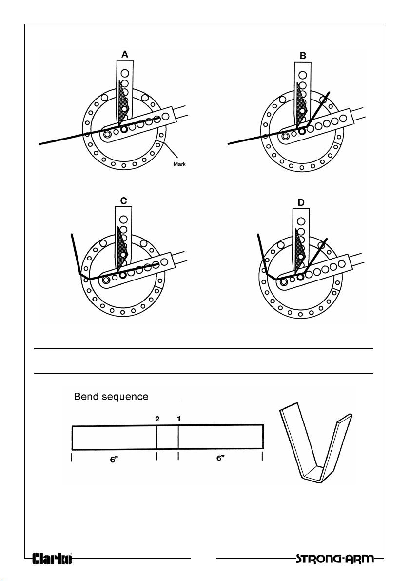
LETTER V
STOCK REQUIRED:
• 3/16” STOCK; 2” MAX WIDTH
• 1 X 13-1/2” Blank
42

SETUP
Make chalk marks on the 5-13/16-in. blank as shown on the “Bend Sequence.”
BEND NO. 1
Insert the blank into the bender to the #1 chalk mark
(as in A), and bend it to 75°.
BEND NO. 2
Slide the blank to the #2 chalk mark (as in B), and bend it to 75°. To remove the
part, pull the pin in the sharp-angle-bend attachment.
FINISHING
Grind and sand all sharp corners.
LETTER W
STOCK REQUIRED:
• 3/16” STOCK; 2” MAX WIDTH
• 2 x 13-1/2” Blanks
Make the letter “W” by tack-welding
together two letter “V”s (the same
as a letter “M”, page 33).
43

LETTER X
STOCK REQUIRED:
• 3/16” STOCK; 2” MAX WIDTH
• 2 x 7-1/2” Blanks
SETUP
Make chalk marks on the blank as shown on the “Bend Sequence.”
BEND
Insert the blank into the Bender to the chalk mark, and bend it until the outside
dimension is 6 in. (as shown).
FINISHING
Tack-weld the two pieces together. Check that the parts are parallel. Grind
and sand all sharp corners.
LETTER Y
STOCK REQUIRED:
• 3/16” STOCK; 2” MAX WIDTH
44
• 1 x 9-1/2” Blank
• 1 x 3-3/4” Blank
SETUP
Make chalk marks on the blank as shown on the “Bend Sequence.”
BEND NO. 1
Insert the blank into the Bender to the #1 chalk mark (as in A), and bend it to
80°. Re-check the angle.
BEND NO. 2
Slide the stock to the #2 chalk mark (as in B), and bend it to 80°. Re-check the
angle.
To remove the part, pull the pin from the sharp-angle-bend attachment.
FINISHING
Grind and sand all sharp corners.
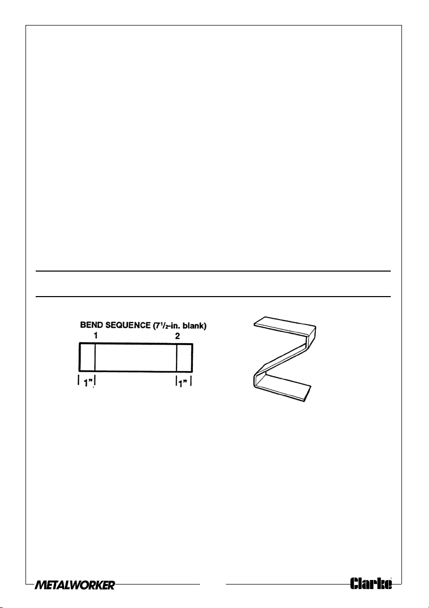
LETTER Z
STOCK REQUIRED:
• 3/16” STOCK; 2” MAX WIDTH
• 2 x 7-1/2” Blanks
SETUP
Make chalk marks on the 7-1/2” blank as shown on the “Bend Sequence.”
BEND NO. 1
Insert the blank into the Bender to the #1 chalk mark (as in A), and bend it to
50°. Re-check the angle.
45

BEND NO. 2
Reverse the part end-for-end. Slide it to the #2 chalk mark (as in B), and bend it
to 50°.
FINISHING
Tack-weld the bent piece to the two 4-1/2” pieces. The legs of the ”Z” should
be parallel, 6” apart. Grind and sand all sharp corners.
COMPONENT PARTS
46
Item Description
1 Spacer, loop
2 Bolt, ⅜ x
3 Washer, flat, ⅜
4 Ring Assembly
5 Bolt, flat-head ⅜ in
6 Spacer, ring
7 Lockwasher ⅜ i
8 Nut ⅜ in
4⅛ in
n

ITEM DESCRIPTION ITEM DESCRIPTION
9 Hich Pin - long 19 Sharp angle bend attachment
10 Stop Block 20# Stand (CCB1B)
11 Support block 20# Stand (CCB2B)
12 Bolt, ⅜ x 1⅛ in 21 Die - 1-in
13 Adjustable stop 22
14 Fixed stop 23
15 Hitch Pin-short 24
16 Handle extension 25 Die - 2-in
17 Pin with clip 26
18 Handle 27 Die - 3-in
47
¼-in
Die - 1
Die - 1
½-in
Die - 1¾-in
Die - 2½-in

 Loading...