

Page 1

Warning!
Table of Contents
THE CLARION VMA6593 MONITOR IS ONL Y DESIGNED TO BE
VIEWED BY REAR-SEAT OCCUP ANTS.
DIGITAL VIDEO PRODUCTS ARE NOT INTENDED FOR VIEWING BY THE DRIVER WHILE THE VEHICLE IS IN MOTION.
SUCH USE MA Y DISTRACT THE DRIVER OR INTERFERE WITH
THE DRIVER’S SAFE OPERATION OF THE VEHICLE, AND
THUS RESULT IN SERIOUS INJUR Y OR DEATH. SUCH USE
MA Y ALSO VIOLATE ST A TE LAW .
CLARION DISCLAIMS ANY LIABILITY FOR ANY BODIL Y
INJURY, INCLUDING FATALITIES, OR PROPERTY DAMAGE
THAT MAY RESULT FROM ANY IMPROPER OR UNINTENDED USES OF THIS PRODUCT.
About Installation
Installation of mobile audio and video components requires
experience with a variety of mechanical and electrical procedures. Even though this manual provides general installation
and operation instructions for your new Clarion VMA6593
Widescreen Video Monitor, it does not show the exact
installation methods for your particular vehicle.
If you do not have the required knowledge and experience to
successfully complete the installation, we strongly recommend
consulting an authorized Clarion dealer about professional
installation options.
1. Introduction .................................................................... 2
2. Care and Maintenance ..................................................3
3. Using the VMA6593 ........................................................3
4. Installation and Wiring ................................................... 6
5. Troubleshooting ........................................................... 15
6. Specifications ...............................................................15
7. Limited Warranty Information ..................................... 16
Page 2

1. INTRODUCTION
The Clarion VMA6593 is a high-performance video monitor
designed specifically for the mobile environment. It is
intended for use with other Clarion multimedia products, and
can also be integrated with many other products as part of a
complete mobile video solution. With two video inputs, the
VMA6593 can support simultaneous connection to both
dedicated video source units and optional audio/video
components such as camcorders or videogames. The
infrared remote control receiver output allows integration with
select Clarion DVD and VHS source units.
The VMA6593 automatically switches to operate with either
NTSC or PAL video signals (NTSC is the standard North
American video format).
The 16:9 aspect ratio screen allows DVD films to be viewed
in their original aspect ratio for the best cinematic experience.
Note:
• The VMA6593 is designed to be a component in a full audio/
video system. If you have any questions about compatible
components, such as system controllers, source units, FM
modulators, or other audio/video products, please contact your
authorized Clarion dealer.
What is included with the VMA6593
• The VMA6593 monitor unit
• The wiring harness
• A flush-mount trim bezel
• Owner’s Manual / Installation Guide
FCC Approval
This equipment has been tested and found to comply with the
limits for a Class B digital device, pursuant to Part 15 of the
FCC Rules. These limits are designed to provide reasonable
protection against harmful interference in a residential
installation. This equipment generates, uses, and can radiate
radio frequency energy and, if not installed and used in
accordance with the instructions, may cause harmful interference to radio communications. However, there is no guarantee that interference will not occur in a particular installation. If
this equipment does cause harmful interference to radio or
television reception, which can be determined by turning the
equipment off and on, the user is encouraged to consult the
dealer or an experienced radio/TV technician for help.
2 VMA6593
Page 3
2. CARE AND MAINTENANCE
ACC or engine
ON position
3. USING THE VMA 6593
Liquids and the VMA6593
Keep all liquids, including beverages and cleaning liquids,
away from the VMA 6593. Liquids inside the monitor can
damage the electronics, and result in electrical shock or fire.
If the unit should become wet, turn off all power and contact
an authorized Clarion dealer to have the monitor inspected.
Servicing the VMA6593
In the event that trouble arises, never open the case or
disassemble the unit. The internal parts are not serviceable
by the user. Opening any components will void the warranty.
CAUTION!
Changes or modifications to this product not
approved by the manufacturer will void the
warranty and will violate FCC approval.
In order to operate the VMA6593, the vehicle ignition key
switch must be in the ACC or RUN position.
WARNING!
To prevent the battery from going dead,
operate this unit with the engine
running, if possible.
VMA6593 3
Page 4
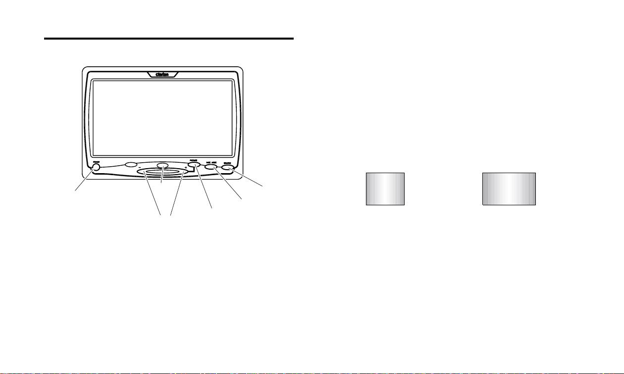
Front-Panel Controls
6.5 INCH WIDE LCD MONITOR
The [SOURCE] button selects between the two video inputs of
the VMA6593.
Note:
• If only one of the video inputs is used, the screen will remain dark
when the unused input is selected.
The [WIDE] button changes the display mode from “wide”
16:9 mode to “normal” 4:3 mode.
POWER
IR
receiver
(+) and (-)
adjustment keys
PICTURE
SOURCE
WIDE
The [POWER] button turns the VMA6593 on and off.
Notes:
• Even after the VMA6593 is switched on, the screen remains dark
until a video signal is detected.
• When the ignition switch is turned off, the VMA6593 automatically
shuts off. The next time the ignition switch is turned on, the
VMA6593 will remain off until the [POWER] button is pressed.
4 VMA6593
4:3
16:9
Note:
• When using a DVD player as the source unit, make sure that the
DVD player’s output mode is set to “Wide” or “16:9”, so that it will
generate a video signal that can take advantage of the
VMA6593’s aspect ratio. When using this display with sources
that generate a “normal”, 4:3 image signal, such as videogames
and videocassette players, the [WIDE] button will “stretch” the
image to fit the screen. In this case, some minor image distortion
may be visible.
Page 5
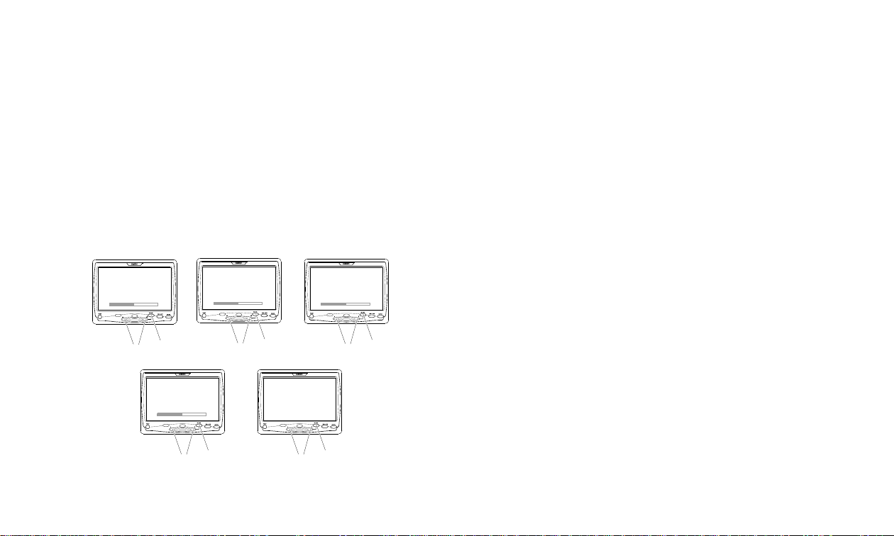
The [PICTURE] button accesses the display adjustment
menus. Each time this button is pressed, the unit will step to
the next setting mode, and the screen will display the value of
the selected setting. These adjustment settings are:
Brightness
Contrast
Color
Tint
Mem Reset (resets above to original values)
Change the value of each setting by pressing the [+] and [-]
buttons. Each setting has 42 steps of adjustment range.
6.5 INCH WIDE LCD MONITOR
BRIGHTNESS
(+) and (-)
adjustment keys
PICTURE
6.5 INCH WIDE LCD MONITOR
CONTRAST
(+) and (-)
adjustment keys
PICTURE
6.5 INCH WIDE LCD MONITOR
COLOR
(+) and (-)
adjustment keys
PICTURE
Note:
• When the “MEM RESET” option is displayed on the screen,
pressing either the [+] or [-] buttons will reset all settings to
their original factory values. If you do not wish to reset the
settings, either press the [PICTURE] button again, or wait for the
monitor to exit the picture adjustment mode automatically.
Note:
• If the “MEM RESET” option is used and the VMA6593 is set to
Source 2, the monitor will revert to the default setting of Source 1.
If there is no active input on Source 1, the screen may go dark. If
this happens, press the [SOURCE] button to switch the monitor
back to Source 2.
The IR Receiver detects the signals from infrared remote
controls that are included with optional Clarion video source
units. Aim remote controls at this IR receiver during use.
Note:
• The IR Receiver only functions with select Clarion multimedia
equipment.
6.5 INCH WIDE LCD MONITOR
6.5 INCH WIDE LCD MONITOR
TINT
MEM RESET
(+) and (-)
adjustment keys
PICTURE
(+) and (-)
adjustment keys
PICTURE
VMA6593 5
Page 6

6. INSTALLA TION AND WIRING
1. Before Starting
Read these instructions and the following precautions carefully.
WARNING!
Be sure to disconnect the battery (-)
terminal before starting. This is to
prevent short circuits during installation.
Precautions
• This unit is exclusively for cars with a negative ground, 12V
power supply.
• Do not open the case. There are no user-serviceable parts
inside. If you require asistance, consult your Clarion dealer
or an authorized Clarion service center.
• Use a soft, dry cloth to clean the screen. Never use a
rough cloth, thinner, benzene, alcohol, or other solvent. The
screen surface is easy to scratch - do not rub it when
cleaning.
2. Package Contents
1 VMA6593 monitor unit
2 Flush-mount trim bezel
3 Wiring harness
4 Owner’s Manual / Installation Guide
3. Installation Requirements
WARNING!
Never install this monitor where it is
visible from the driver’s seat, or where it
could injure any vehicle occupant in
case of an accident. Ensure that your
installation does not create risk of headstrike injury, and that the monitor will
remain securely mounted in the case of
an accident or sudden maneuver.
6 VMA6593
Page 7

4. Installing the VMA6593
The VMA6593 is designed for custom installation. While a
basic flush-mount bezel is supplied, you may need parts that
are not included (depending on your installation). Clarion
also offers optional mounting kits - the ZMT003 is a flexible
“gooseneck” mount, and the PQE023 positions the monitor
on the back of a vehicle headrest.
Note:
After you cut the opening, route the DIN-connector end of the
wiring harness into the opening from the rear out the front.
Insert the trim bezel and route the wiring harness through the
opening in the rear.
Firmly attach the bezel to the mounting surface and/or to the
interior of the mounting surface.
• The Clarion HRM100 and HRM150 headrest mounting kits are not
compatible with this monitor.
WARNING!
Always use great care when attaching
anything to a vehicle! Visually inspect
all sides of any potential screw location,
to insure no damage will occur. If you
have questions about this process, see
your authorized Clarion dealer.
Flush mounting
The included trim bezel can be used to flush-mount the
monitor.
Before cutting the opening for the trim bezel, ensure that you
will have sufficient clearance for the monitor and its rearlocated wiring harness.
Wire harness opening
Mounting
tabs
Mounting
screw
holes
CAUTION!
NEVER press on the surface of the screen!
Gently press on the edges of the monitor case.
If you find that you cannot insert the monitor
without excessive force, you may need to check
your wire harness position for interference with
the insertion process. You may also need make
the opening slightly larger.
VMA6593 7
Page 8

Connect the wiring harness to the monitor, and tuck the
excess wiring harness length carefully out of the way behind
the bezel.
Gently insert the monitor into the bezel. Press only on the
edges of the monitor, not on the screen. You will hear a few
soft “clicks” as the monitor locks into place.
Inserting the monitor into the bezel:
Removing the monitor from the bezel
To remove the monitor from the bezel, insert a flat card (such
as a credit card) between the monitor case and the side of
the bezel to release the spring clips.
8 VMA6593
Insert card
Page 9

Custom Mounting using the threaded insert
5. Wiring the VMA6593
The base of the VMA6593 has a threaded insert (1/4 - 20).
This insert can be used with the optional Clarion ZMT009
gooseneck mounting kit or with a 1/4 -20 machine screw in
custom applications.
The following pages display wiring diagrams for various
VMA6593 configurations.
Read the following precautions before wiring your system.
• Disconnect the negative battery terminal before making
any wiring connections.
• Be particularly careful where you route wires. Keep them
away from the engine, exhaust system, etc. Heat may
damage wires.
• If the fuse should blow, make sure all connections are
correct and no wires are damaged before replacing the
fuse. Always use fuses that are the same amperage value
as the original. When replacing a fuse, never let the battery
side touch any metal part or any other wire.
WARNING!
Be sure to disconnect the battery (-)
terminal before starting. This is to
prevent short circuits during installation.
VMA6593 9
Page 10
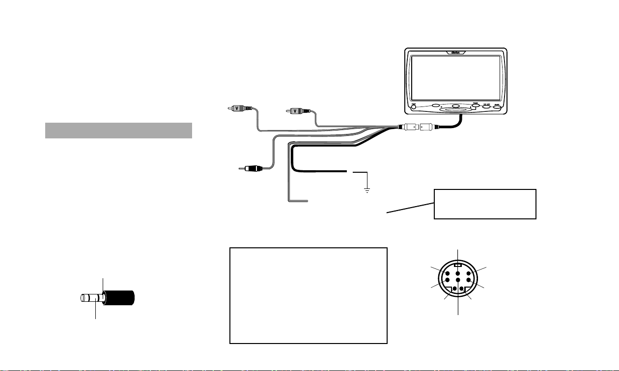
VMA6593 Connections
CAUTION!
Some non-Clarion automotive DVD
and VCP source units use a similar
connector for an external IR receiver, but use different pin polarity
than the VMA6593! Connecting nonClarion source equipment to this
connector could cause equipment
damage not covered by the warranty!
IR connector polarity:
(+) V ACC
IR DATA LINE
Video input 2
Video
input 1
IR
receiver
output
Red
+12V Accessory
DIN Connector Pin Assignments
Pin Description
1 Red 12V (+) ACC
2 Infrared receiver signal
3 Black Ground (-)
4 Yellow Video input 1
5 Video signal ground
6 Not used
7 Yellow video input 2
8 Not used
Black Ground
6.5 INCH WIDE LCD MONITOR
Clarion
VMA
6593
ALWAYS use a 3A fuse
on this connection!
2
1
4
7
5
3
6
8
10 VMA6593
Page 11

VMA6593 Monitor with VS735 DVD Player
Audio output - to head unit with volume control
or Clarion FM200 FM Modulator
Video
input 1
Video output to monitor
A/V Auxiliary inputs
Video input 1
IR input
Video input 2
6.5 INCH WIDE LCD MONITOR
Clarion
VMA
6593
A/V Output
Optical
digital
output
VS 735
Power Harness
Red +12V
Accessory
Black Ground
Black - Ground
Red +12V Accessory
Yellow +12V Constant Power
VMA6593 11
Page 12
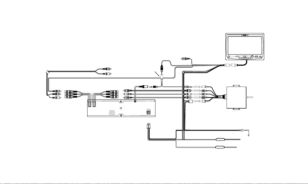
VMA6593 with VS735 DVD Player and TTX001 TV Tuner
Audio output - to head unit with volume control
or Clarion FM200 FM Modulator
Video
input 1
Video output to monitor
A/V Output
A/V Auxiliary inputs
3-conductor
(not supplied)
Video input 1
VS 735
"Y"-cable
IR input
Video input 2
Red +12V ACC
Black - Ground
Power
Harness
6.5 INCH WIDE LCD MONITOR
Clarion
TTX 001
TV Tuner
VMA
6593
Antenna
ZCB 001
Optical
Notes:
•
This system requires a 3.5mm stereo “Y” cable, Radio Shack
digital
output
P/N 42-2496. A 3.5mm male-to-female stereo extension may
also be required if the TTX001 and the VS735 are installed in
separate locations (P/N varies by length).
• The TTX001 is connected to the VS735 to allow the VS735 to
control both audio and video switching. Do not use the Video
2 input of the VMA6593 for the TTX001 in this instance.
12 VMA6593
Power Harness
Black - Ground
Red +12V Accessory
Yellow +12V Constant Power
Page 13
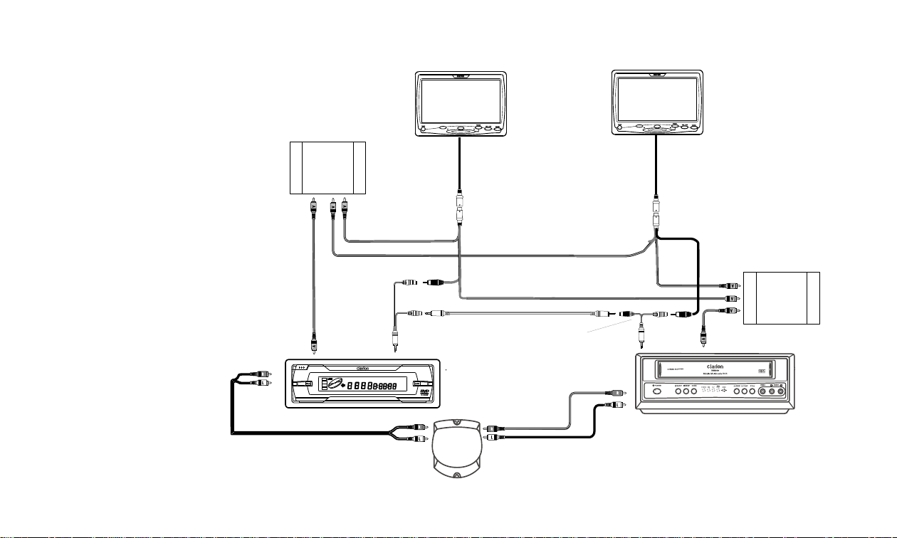
Two VMA6593 monitors, with a VS735 DVD Player, a
VDH910 VCP, and the WH200 Two-channel Wireless
Headphone kit.
Notes:
•
This system requires two 3.5mm
stereo “Y” cables, Radio Shack
P/N 42-2463. These are used to
allow the IR command lines to be
shared between both source units
and both monitors. A 3.5mm maleto-male extension may also be
required (P/N varies by length).
• The WH200 Two-channel
Wireless Headphone Kit allows
headphone users to independently
select from two different audio
sources.
• Two VA700 Video Amplfiers are
used to allow two monitors to
operate from one video output.
• Clarion also makes several
audio integration and video
switching products for more
complex installations - see
your Clarion dealer for more
information on these products.
L and R
audio
output
VA700
Video
Input
VA700
Video
Amplifier
OPEN
POWER
VS 735 DVD
VA 700
Video
Output
VA 700 Video Output
Mini stereo
"Y"-cable
(not supplied)
Video
Output
A
SCN
REPEAT
DVD
TITLE
CHP
RDM
VCD
CD
L/R
MP3
B
TRK
REMAIN
DOLBY
ANGLE
DIGITAL
6.5 INCH WIDE LCD MONITOR
Video input 1
IR
output
IR input
VMA
6593
Video input 2
Mini stereo extention (not supplied)
Mini stereo
"Y"-cable
(not supplied)
WH 200
2-channel
HP Kit
Video input 1
6.5 INCH WIDE LCD MONITOR
VA 700 Video Output
IR input
L and R
audio
output
VMA
6593
IR
output
Video
input 2
VDH 910 VCP
VA700
Video
Input
VA700
Video
Amplifier
VMA6593 13
Page 14

6. TROUBLESHOOTING
7. SPECIFICA TIONS
No picture.
Press the [SOURCE] button to make sure the proper input is
selected.
If there is still no picture, press the [PICTURE ] button. If the
menu appears, check the source unit and video connections.
If no menu appears, check all fuses and power connections
to the VMA6593 and the associated equipment.
Note:
•
The VMA6593 has an operating temperature range of
o
-1
C to 45o C (30o F - 113o F). If the temperature is outside this
operating range, the unit will not turn on, or the screen
may be slow to react to image changes. The monitor will
function normally once it returns to its proper operating
range.
With a DVD player and a widescreen DVD disc, there are
black bars on the screen.
Change the TV display mode to “Wide” in the DVD player’s
Setup menu.
After changing this setting, if there are still black bars, press
the [WIDE] button on the front panel of the VMA6593.
Supply voltage: 12V DC (9V-16V)
Test voltage: 12V, negative ground
Current consumption: Less than 750 milliAmps
Operating Temperature: -1o C to 45o C (30o F to 113o F)
Signal system: NTSC and PAL composite video 1.0Vp-p
Screen: 6.5” diagonal, 144.4mm x 80.3 mm.
Resolution: 1200 x 280 (280,000 pixels)
Weight: 0.5 kg
Note:
• The technical data and the design of the equipment may change
for the sake of technical improvements without prior notice.
14 VMA6593
Page 15

LIMITED WARRANTY INFORMATION
For USA and Canada only
This product is warranted against all defects in material workmanship
for a period of one year from the date of original purchase. Clarion
ProAudio products, except for speakers, are covered by a two year
limited warranty when installed by an authorized Clarion dealer. The
conditions of this limited warranty and the extent of responsibility of
Clarion Corporation of America (“Clarion”) under this limited warranty
are as follows:
1. PROOF OF DATE OF PURCHASE WILL BE REQUIRED FOR
WARRANTY SERVICE OF THIS PRODUCT. IN THE CASE OF THE
TWO (2) YEAR LIMITED WARRANTY FOR CLARION PROAUDIO
PRODUCT, PROOF OF INSTALLATION BY AN AUTHORIZED
DEALER IS REQUIRED. INFORMATION ABOUT CLARION
AUTHORIZED WARRANTY SERVICE CENTERS MAY BE OBTAINED
BY CONTACTING CLARION AT THE ADDRESS BELOW.
2. This limited warranty will become void if service performed by
anyone other than an approved Clarion Warranty Service Center
results in damage to the product.
3. This limited warranty does not apply to any product which has
been subject to misuse, neglect or accident, or which has had the
serial number altered, defaced or removed, or which has been
connected, installed, adjusted or repaired, other than in
accordance with the instructions furnished by Clarion.
4. This limited warranty does not cover car static or other electrical
interferences, tape head or laser pick-up cleaning or adjustments,
or labor costs for the removal or reinstallation of the unit for repair.
5. The sole responsibility of Clarion under this limited warranty shall
be limited to the repair of the product or replacement of the
product, at the sole discretion of Clarion.
6. Product must be shipped in its original carton or equivalent carton,
fully insured, with shipping charges prepaid. Clarion will not
assume any responsibility for any loss or damage incurred in
shipping.
7. ALL IMPLIED WARRANTIES EXCEPT TO THE EXTENT PROHIBITED
BY APPLICABLE LAW SHALL HAVE NO GREATER DURATION
THAN THE WARRANTY PERIOD SET FORTH ABOVE. UNDER NO
CIRCUMSTANCES SHALL CLARION BE LIABLE FOR ANY LOSS OR
DAMAGE, DIRECT OR CONSEQUENTIAL, ARISING OUT OF THE
USE OR INABILITY TO USE THE PRODUCT. BECAUSE SOME
STATES DO NOT ALLOW LIMITATIONS ON HOW LONG AN IMPLIED
WARRANTY LASTS OR EXCLUSIONS OR LIMITATIONS OF
INCIDENTAL OR CONSEQUENTIAL DAMAGES, THE ABOVE
LIMITATIONS OR EXCLUSIONS MAY NOT APPLY TO YOU.
8. THIS LIMITED WARRANTY GIVES YOU SPECIFIC LEGAL RIGHTS,
AND YOU MAY ALSO HAVE OTHER RIGHTS WHICH VARY FROM
STATE TO STATE.
9. Should you have any difficulties with the performance of this
product during the warranty period, please call or visit our web
site (www.clarion.com) for a listing of Authorized Warranty
Service Centers in your area. You may also contact Clarion at the
address listed below.
In USA:
Clarion Corporation of America
Attn: Customer Service Manager
661 W. Redondo Beach Blvd
Gardena, CA. 90247-4201
1-800-GO-CLARION
(310)327-9100
www.clarion.com
In Canada:
Clarion Canada, Inc.
Warranty Service Center
2239 Winston Park Drive
Oakville, Ontario L6H 5R1
(905)829-4600
www.clarioncanada.com
VMA6593 15
Page 16

16 VMA6593
 Loading...