

㼄㼍㼚㼍㼢㼕㻌㻵㼚㼒㼛㼞㼙㼍㼠㼕㼏㼟㻌㻯㼛㼞㼜㼛㼞㼍㼠㼕㼛㼚
㻯㻻㻺㻲㻵㻰㻱㻺㼀㻵㻭㻸
INSTRUCTION MANUAL OF UGZZ5-X02
p
[
]
A
A
Y
A
1. BLUETOOTH MODULE SPECIFICATION
1-1. PRODUCT NAME
UGZZ5-X02
1-2. MANUFACTURE
ALPS ELECTRIC
1-3. FEATURES
Bluetooth䉼 S
Complete type of Bluetooth module, built-in various profile
Built-in Link controller, Link Manager Protocol
Output Power class2 compliant
Type with a chip antenna
Full custom package with pwb can be fit to only navigation products made by Xanavi
Built-in Flash memory(8Mbit), system clock 26MHz(OSC)
BtoBinterface
1-4. SPECIFICATION
1-4-1. MECHANICAL SPECIFICATION
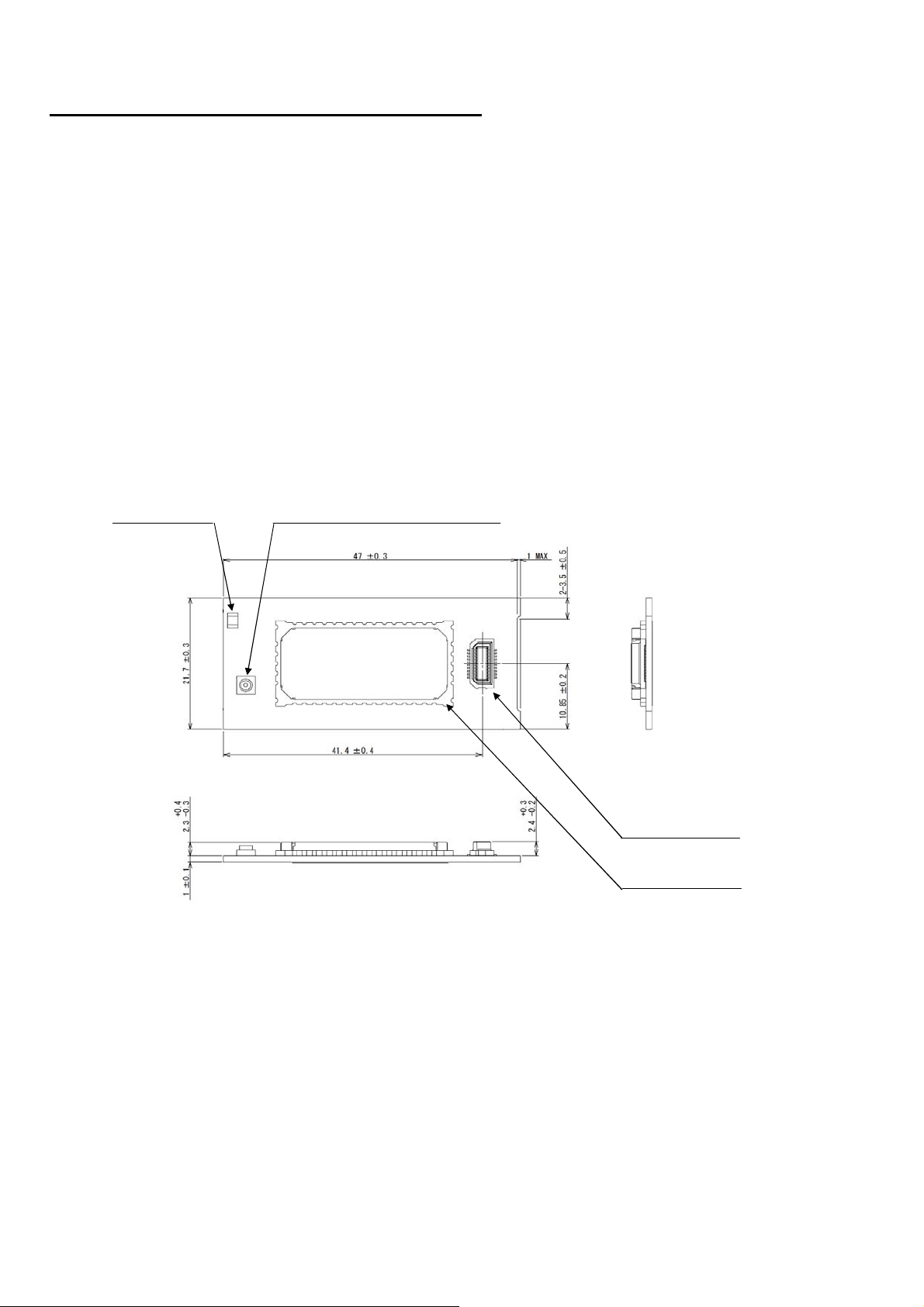
1-4-1-1. EXTERNAL DIMENSIONS
ecification V1.2 support
Refer to the following page.
Chip Antenna
TAIYO YUDEN
F216M245001
1-4-1-2. MASS
4.4 [g]
Coaxial Connectors with Switch
Murata Manufacturing
MM8430-2610
BtoB Connector
Matsushita Electric
XK620347
BLUETOOTH MODULE
LPS ELECTRIC
UGZZ5-611B
1-4-2. ELECTRIC SPECIFICATION
1-4-2-1. POWER-SUPPLY-VOLTAGE
1-4-2-2. TEMPERATURE RANGE
1-4-3. RF SPECIFICATION
1-4-3-1. NORMAL TRANSMIT POWER(AVERAGED POWER)
1-4-3-2. REFERENCE SENSITIVITY LEVEL(BER=0.001%)
DC +3.1 to +3.5 [V]
-30 to +85 [degree C]
-6 to +4
MAX. -70 [dBm]
dBm
INSTRUCTION MANUAL OF NAU-P8100EU - 1 / 5 -

㼄㼍㼚㼍㼢㼕㻌㻵㼚㼒㼛㼞㼙㼍㼠㼕㼏㼟㻌㻯㼛㼞㼜㼛㼞㼍㼠㼕㼛㼚
㻯㻻㻺㻲㻵㻰㻱㻺㼀㻵㻭㻸
1-5. LABEL INFORMATION
/
Reset(Active Low)
BOOT Enable
Audio Clock
X
UART_RX
AV/HF Output
HF/AV Status signal
PCM_Reset(Active Low)
r
1-5-1. LABEL LAYOUT
1-5-2. CONTENTS OF LABEL
UGZZ5-X02(Back View)
FCC ID: SJ2HGZ0024
IC ID:5527A-HGZ0024
Model Number Rev. Number
Label
Xanavi Parts Numbe
TELEC Mark & ID
1-6. CONNECTOR PIN ASSIGNMENT
BtoB Connector terminal NO.
Lot Number
FCC/IC ID
FCC ID: SJ2HGZ0024
IC ID:5527A-HGZ0024
Company Name
NO. PIN NAME NO. DESCRIPTION
1 VCC I Power Supply 3.3V
2 GND - Ground
3 PTB1 O AV Master Clock Select(44.1kHz=Low, 48kHz=High)
4PTE0O
5PTA5O
6 SIOF_SYNC O Audio Frame signal
7SIOF_TXDO
8 GND - Ground
9 SCIF0_RTS O UART_RTS
10 SCIF0_CTS I UART_CTS
11 SCIF0_RXD I
12 SCIF0_TXD O UART_T
13 SIOF_SCK O
14 SIOF_RXD I AV/HF Input
15 CLK11/12M I AV Master clock Input
16 PTA6 I MODE Select
17 BOOT_E I
18 PTE5 O PCM_Mute
19 RESETP
20 VCC I Power Supply 3.3V
I
INSTRUCTION MANUAL OF NAU-P8100EU - 2 / 5 -

㼄㼍㼚㼍㼢㼕㻌㻵㼚㼒㼛㼞㼙㼍㼠㼕㼏㼟㻌㻯㼛㼞㼜㼛㼞㼍㼠㼕㼛㼚
㻯㻻㻺㻲㻵㻰㻱㻺㼀㻵㻭㻸
1-7. BLOCK DIAGRAM
2. PROCEDURE TO BUILD IN
2-1. PROCEDURE FOR UGZZ5-XO2
(1)Install UGZZ5-X02 to BT-CAP
BT-CAP
SLIDE
(2)Connect BT-MODULE-AS to FRONT PCB by BtoB connection
Tighten up a screw in order of one to two. After Connect BT-MODULE-AS to FRONT PCB
FRONT PCB
UGZZ5-X02
After install UGZZ5-X02 to BT-CAP
(BT-MODULE-AS)
BOARD-GUIDE
Slide to 4 points of Board-guide, and sandwich the module.
by BtoB connection (FRONT-PCB-AS)
B to B connection
INSTRUCTION MANUAL OF NAU-P8100EU - 3 / 5 -

㼄㼍㼚㼍㼢㼕㻌㻵㼚㼒㼛㼞㼙㼍㼠㼕㼏㼟㻌㻯㼛㼞㼜㼛㼞㼍㼠㼕㼛㼚
㻯㻻㻺㻲㻵㻰㻱㻺㼀㻵㻭㻸
(3)Install FRONT-PCB-AS to Navigation-unit
(5)
(6)
B to B connection
Tighten up a screw in order of one to four.
CONDUCTIVE SHEET
Connect FRONT-PCB-AS to Navi-board
by FCC cable connection.
(4)Install DVD-AS to Navigation-unit
Install UPPER-COVER to Navigation-unit
Install FRONT-COVER to Navigation-unit
(7)Install REAR-COVER to Navigation-unit
UGZZ5-X02 installationposition
ChipAntennaposition
INSTRUCTION MANUAL OF NAU-P8100EU - 4 / 5 -

㼄㼍㼚㼍㼢㼕㻌㻵㼚㼒㼛㼞㼙㼍㼠㼕㼏㼟㻌㻯㼛㼞㼜㼛㼞㼍㼠㼕㼛㼚
㻯㻻㻺㻲㻵㻰㻱㻺㼀㻵㻭㻸
p
g
3. NOITCE
-Operation is subject to the following two conditions:
(1) this device may not cause interference, and
(2) this device must accept any interference, including interference that may cause undesired operation of the device.
-Any changes or modifications not expressly approved by the party responsible for compliance could void
the user's authority to operate the equipment.
-Please note that this users manual should not be
-The followin
"Contains Transmitter Module FCC ID: SJ2HGZ0024", or "Contains FCC ID: SJ2HGZ0024"
-This equipment complies with FCC RF radiation exposure limits set forth for an uncontrolled environment.
sentence has to be displayed on the outside of the device in w hich the module is installed:
rovided to end-users.
INSTRUCTION MANUAL OF NAU-P8100EU - 5 / 5 -
 Loading...