

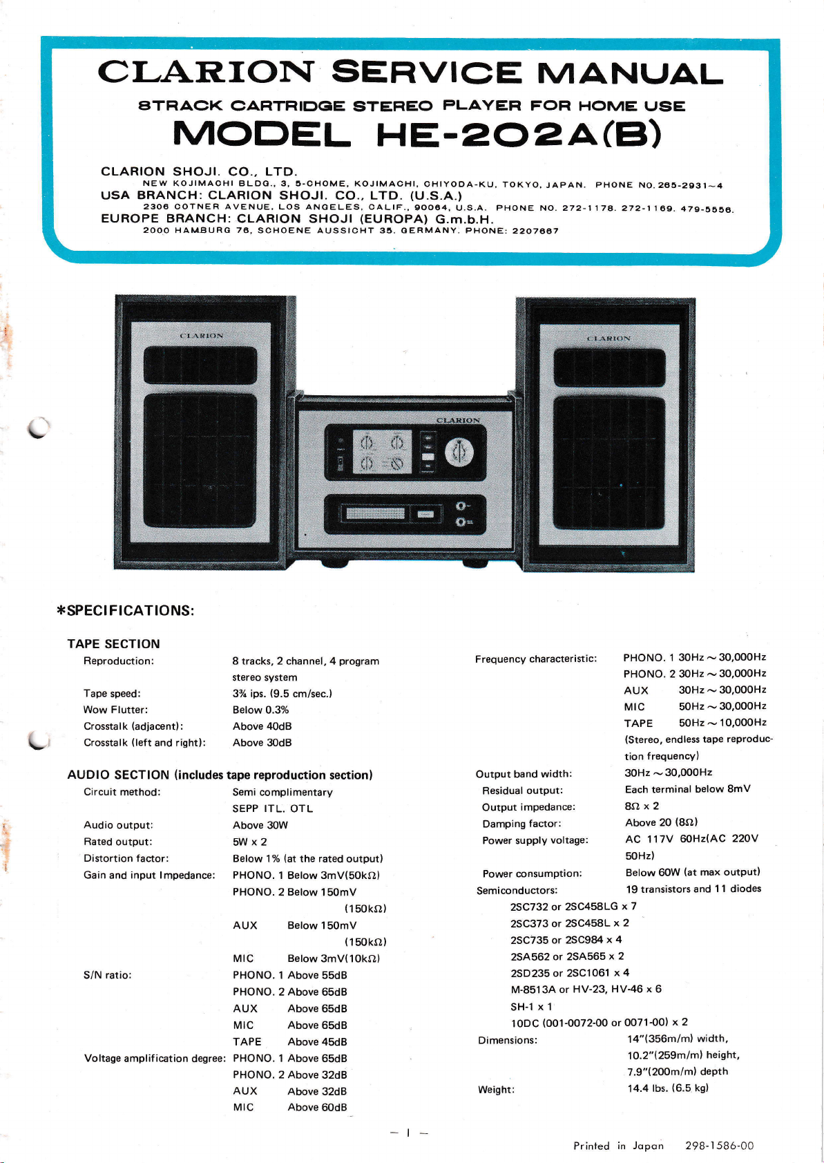
Page 1
Cf-AR.IOI\T
SEFIVIC)T
MANLJAL
L
ATRAC}<
MODEL
CLARION
UsA
EUROPE BRANCH:
SHOJI. CO., LTD.
NEW KOJIMACHI BLDC.,3, 5-CHOME,
BRANCH: CLARION
2306 COTNER AVENUE,
2OoO HAMBURG 76,
CARTRIDGE
STEREO
PLAYEFI
HE.ZOZA(B)
SHOJI. CO., LTD.
CLARION SHOJI
LOS ANGELES, CALrF.,90064,
SCHOENE AUSSIOHT 35. OERMANY. PHONE:
KOJIMACHI,
(EUROPA)
OHIYOOA.KU,
(U.S.A.)
G.m.b.H.
u.s.a.
ÏOKYO,
pHoNE
2207ao7
FOR
HOME IJSE
JAPAN.
No.272-1178.272-1'l
PHONE
NO.265-2931-4
69. 479-5556.
:I.SPECIFIGAT!ONS:
TAPE SECTION
Reproduction:
Tape
speed:
Wow Flutter:
Crosstalk
L
Crosstalk
AUDIO
SECTION
Círcuit
Audio
output:
Rated
output:
Distortion factor:
Gain and input lmpedance:
ratio:
S/N
Voltage
(adjacent):
(left
method:
amplif
and right):
(includes
ication
degree:
8 tracks, 2 channel, 4
stereo system
(9.5
37c ips.
Below
Above 40dB
Above
tape reproduction
Semi complimentary
SEPP
Above 3OW
5Wx2
Below lYo
PHONO.
PHONO.
AUX
Mtc
PHONO. 1 Above
PHONO.
cm/sec.)
0.37o
3OdB
ITL.
OTL
(at
the rated output)
1 Below 3mv(50ko)
Below
2
Below 150mV
Below
Above
2
AUX Above
Mtc
ïAPE
PHONO. 1 Above
PHONO.
AUX
Mtc Above
Above
Above
2 Above
Above
program
section)
150mV
(150ko)
(150ko)
3mV(10kO)
55dB
65dB
65dB
65dB
45dB
65dB
32dB
32dB
60dB
Frequency
Output band
Residual
Output
Damping
Power supply
Power consumption:
Semiconductors:
Dimensions:
Weight:
characteristic:
width:
output:
impedance:
factor:
voltage:
or 2SC458LG
25C732
or 2SC458L
2SC373
or 2SC984
2SC735
25A562
2SD235
M-851 3A
x 1
SH-l
(OO1-0072-00
lODC
or 25A565
or 2SC1061
HV-23, HV-46
or
PHONO.
PHONO. 2 30Hz
AUX 30Hz
MIC 50Hz
TAPE
(Stereo,
frequencyl
tion
30Hz
-
Each terminal
8Ox2
Above 20
AC 117V
50Hz)
Below 60W
19 transistors
x 7
x 2
x 4
x
2
x 4
x
6
or 0071-001
14"(356m/m)
1O.2"1259mIm)
7.9"(200m/m)
lbs.
14.4
í 30Hz
50Hz
endless
30,000H2
below 8mV
(8O)
6OHz(AC
(at
and
x 2
width,
(6.5
kgl
30,0O0H2
-
-30,000H2
30.0O0H2
-
-30,0O0H2
10,000H2
-
tape reProduc-
220V
max output)
1 1
diodes
height,
dePth
-t-
Printed
in Jopon 298-,l58ó-0C
Page 2
*COMPONENTS:
MICROPHONE
DMA.O48-OOO
HE.2O2A
HA-2022-O4
280-291
280-2851
cAA-o10-000
HE-2028
HA-2022-O5
ss7-00
920-1
CAA-OI0-000
,fiEXTRA
SPEAKER
Specifications:
.
2way
o
Diameter
.
lmpedance:
o
Maximum
.
Output
o
Frequency
.
Dimensions:
.
Weight:
HEAD
PHONE
6-00
-O0
ACCESSORIES:
KIT
SKA.O3O
speaker
of speaker:
permissible
sound
characteristic:
(air
system
input:
pressure:
HPA-OO3.OOO
Main
Owner's
Owner's
pump
Oil
Main unit
Booklet bag
pump
Oil
tight)
bass
treble
8í)
20W
98dB
50
-20,000H2
Width
Height
Length
10 lbs.
unit
guide
guide
6%"
(cone
type)
10.2"(259mlm),
16"(406m/m),
8"(2}2mlml
(4.5
kg)
3"
(16
(7.5
Set
1
Each
í
Each
1
1 Each
1 Set
Each
1
Each
1
cml
cm)
Specifications:
o
Type: Moving type unidirectional
microphone
r
Frequency characteristic: 100
.
lmpedance:
.
Sensitivity:
.
Lead length:
.
Weight:
.
Microphone
stand:
-9,000H2
1oko
-60d8
(2m)
Ít.
6.6
lbs.
2.85
201-01 20-00
*FEATURES
r
Reproduction oÍ
possible.
magnetic or
d ispl ayed.
.
With the LE-301 FM
multi band
phone
is available and by
pleasant
.
Sound in
combined
o
ITL-OTL circuits
mixed
8
By
combined use
crystal
broadcasts
performance
beautiÍul color can
with the color
but the input transformer
semi-complementary
those troubles
maximum
ful aud
o
The compact
signed
bined
and oÍÍice.
with speakers, the unit is well suited Íor both home
due
less than 1o/o
with
io characteristic.
silver color front
with consideration to
track
type stereo
with a
pick-up,
eliminate not only the output transformer
to
excellent record
stereo
can be received. An
employing a dynamic microphone,
can
sound
as well by
lTL.
SEPP.
transformers. Audio output is 30W at
distortion
pack
record
cartridge
be enjoyed.
visually
be
(extra
graph
OTL
panel
ease of operation. When
(130
s)
(cartridge
set, wonderÍul
tape)
player
having
perÍormance
exclusive head
FM
enjoyed when
cost).
the
employment of a
thus doing away with
and
displays wonder-
is
mechanically de-
com-
is
a
is
!_
Specifications:
r
Type:
.
Frequency
o
Maximum
o
lmpedance:
.
Lead length:
.
Weight:
HEAD
PHONE
Specifications:
o
Type:
.
Frequency
o
Maximum
o
lmpedance:
.
Lead length:
e
Weight:
characteristic:
permissible
characteristic:
permissíble
MICROPHONE
Specifications:
o
Type:
.
Frequency
r
lmpedance:
.
Sensitivity:
.
Lead
o
Weight:
o
Microphone
characteristic:
length:
HPA.OOI.OOO
DMA-OsO.OOO
stand:
input:
input:
Moving
coil
phone
20
-29,969t1,
0.5w
8l}
(2m)
ft.
6.6
(440
lbs.
9.7
Moving
coil
phone
,'
50
18,000H2
0.5W
8s,
(2m)
ft.
6.6
(350
lbs.
7.7
Moving
type unidirectional
microphone
100
10,000H2
-
10ko
-64d8
(2m)
6.6 ft.
(350
7.7 lbs.
201-O121-OO
type
s)
type
s)
g)
stereo
stereo
head
head
*GENERAL
OPERATION
o
.
power
The
circuit
displaying superior characteristic. lÍ
circuit is
to an
prevent
short
overcurrent in each circuit
damage,
and right channel
blow, always
The unit
radiation
countered.
lnstall
the unit
(Provide
a
MAINTENANCE AND
INSTRUCTION
stage is composed
circuited,
protecting
power
replace with
should not
be
is unsatisfactory
(BeÍer
to Fig.
place
in a
proper
space between the
a
píopsr
in a
lnstall the unit
(Provrde
of a sem i-complementary
the
transistors will
Íuses
are
supply
a 1A rated fuse.
installed
'1
sections.
in a location
as inductive noíses
)
where heat
plaoe
where
spaco between
the speaker
be
damaged
directly connected. To
provided
lf
a
radiation
unit and the
hoat radiation is
the unit and the wall.)
in
both left
fuse
should
where heat
may be
is
sufficient.
wall).
suÍÍjcient.
due
en-
I
-2-
Page 3
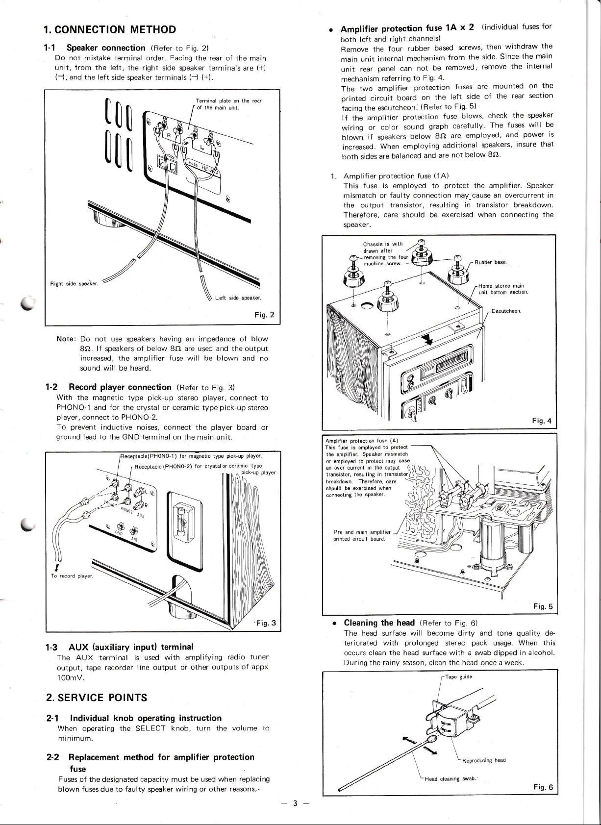
1. CONNECTION METHOD
1-1 Speaker connection
Do not mistake terminal order. Facing the
unit, from the left,
(-),
and
the left
side §peaker terminals
(Refer
the right side
to Fig. 2)
!on
Itt
speaker
(j (+).
Torminal
oÍ the main
rear of the
terminals
plate
on the
unit.
are
main
(+)
rear
Amplifier
left and
both
Remove
main unit
rear
unit
mechanism
two
The
printed circuit
the escutcheon.
Íacing
amplifier
the
lf
or
wiring
if
blown
increased.
both sides
i. AmpliÍier
fuse is
This
mismatch
the
output
ïhereÍore.
speaker.
Chassis
drawn
protection fuse
channels)
right
rubber
four
the
mechanism
internal
panel can not
referring
amplifier
to
protection
board
protection
color sound
speakers
When
are
protection
or faulty
aíter
below
employing
balanced
fuse
employed
connection
transistor,
care
should be exerclsed
wlth
is
x 2
1A
screws,
based
from
removed,
be
4'
Fig.
on
(Hefer
the
to
fuses
left side
Fig'
Íuse
graph carefully'
are
8O
additional
not
are
and
(1A)
protect
to
may-cause
resulting
(individual
withdraw
then
Since
side'
the
are
5)
blows,
employed,
below
remove
mounted
the
of
check
fuses
The
and
speakers,
8O'
the
rear
the speaker
the amplifier.
an
overcurrent in
transistor
in
when connecting the
base.
Rubber
for
fuses
the
the main
internal
the
on
section
will
power
that
insure
Speaker
breakdown.
be
is
L
L,
Right side speikor.
Ngte:
Do
8O.
increased, the amplifier fuse
sound
1-2 Record
With the
PHONO-'l
player,
connect to PHONO-2.
prevent
To
ground
lead to
not use
lf
magnetic type
and for
speakers having
speakers
will
player
of below 8O are used and the
be
heard.
connection
pick-up
crystal
the
inductive
noises,
the GND terminal on the
(PHONO-1) Íór magnotic typo
Receptacle
(Refer
stereo
ceramic
or
connect
(PHONo-2)
an impedance
be blown
will
to
Fig. 3)
player,
pick-up
type
player
the
main unit.
pick-up
ooímic
crystal or
for
Fis.2
blow
of
output
and no
connect to
stereo
board or
playor.
typo
protoction Íuso
AmpliÍieÍ
This Íus is omployéd
the ilplifior.
or omployed to
an
trilsistor,
breakdown.
shouli,
oonnocting
Spoaker mismatch
curront rn the output
ovor
rosulting in transistor
TheÍefore, care
be exorcisod when
tho
protoct
gpeaker.
to
(A)
may
protsct
oaso
Home sloroo
unit bottom sotion.
main
scutcheoG
----
Fis.4
./
To r@ord
day6r.
1-3 AUX
The
output, tape
100mV.
2.
SERVICE
2-1
(auxiliary
AUX terminal is
recorder line
POINTS
lndividual knob operating instruction
When operating the
minimum.
Replacement
2-2
method
input)
used with
output or
SELECT
Íor amplifier
terminal
fuse
to faulty
capacity
speaker
Fuses of the
blown fuses
designaled
due
amplifying
other outputs
radio tuner
appx
of
knob, turn the volume
protection
must be used when
wiring or other
replacing
reasons-.
Fig.
5
o
Cleaning
the
The head surface will
teriorated
occurs
During
to
with
clean the head surÍace with a swab
the
rainy season,
(Refer
head
prolonged
to Fig.
become
stereo
clean the
6)
pack
tone
usage.
dipped
hoad
dirty and
head once a week.
Reproducing
quality
When this
in alcohol.
Fis.
de-
6
-3-
Page 4
.
Motor
CareÍully
hole with
Lubrication
sect ion.
lubrication
apply
two
the attached
is
easily
(ReÍer
or three
pump
oil
performed
to Fig. 7)
drops oÍ oil to
every 1,000 hours.
the
on
rhe
motor oil
main unit bottom
r
AC receptacle
The AC receptacle
(AC
117V
available
however,
receptacle
dangerous.
independent
is
above
for
instructions
220V)
117V
other
located
outtet. This
power
oÍ the
(AC
electrical
rear
on
of the
AC
switch. Power
22OV)
2A.
appliances,
main
117V
Do not
as
such
unit is
an AC
(AC
22OV)
consumption,
employ
practice
a
is
this
is
{.WHEN
(50
Hz
When
the
Remove
main unit
A. Connect
chassis
side of
(Refer
LINE FREoUENCY
Hz)
or 60
the frequency
main unit,
the four
internal mechanism
a white
to
the
the
terminal.
to Fig.8.)
adjust
lead from
right
of
as Íollows.
rubber
(50H2
Home stereo
tS DIFFERENT
power
the
based
from
the
-+6OHz)
(for
lead
Red
Orange lead (for
main unit bottom
source
difÍers from that
screws, then
the side.
section
withdraw the
motor on the bottom
50Hz)
60Hz)
Fig.7
*INDIV!DUAL
1. AMPLIFIER
Power
supply volrage
Output impedance
1-1 Power
A. lmproper power
quality
distortion
heating.
adjusted.
B.
Ouiescent current
Íormed
at the
ln this case,
the
current
20mA).
Measuring
'100
to the
(01
resistor
the followíng
LeÍr
Riqht
1-2 Power
The
of
maximum
voltage
(Upper
V6g
and
distortion
varying
the
of
Normally.
1-3 lndividual
When tape
external
and
vacuum-tube
table.
input terminal
adjustment
Tone
Left
Volume
SECTION
SECTION
.................
quiescent
stage
stage
(crossover
Therefore,
measurement
amplifier
adjust the
Ílowing
method:
-250mA
2-3250-00)
side
stage voltage
values.
(L)
(R)............
side
undistorted
With
.............
of the
lower
waveÍorms
increases.)
30kO semi-f
VCf
is
15
-
input
reproduct
performed
or
voltmeter
quality
adjustment
and
right
balance ...........-...........
adjustment
ADJUSTMENT
.............
quiescent
current
AC 117V,
(AC22OY
BO
current
quiescent
current,
distortion)
current
may
protectíng
leÍt
in the
the fuse
varied,
síde
range,
adjust
(L)
pre
45
30
Íuse_
to
ampliÍier
removed,
and
the
-55mA
-
balance adiustment
power
power
output is
stage transistors
become unsymmetrical,
Therefore, adjust
ixed
17V.
terminal
ion
volume
is
extremely
(012-3249-00).
resisror
voltage gain
or
small,
with a CR
to
obtain
the values
Hz
60
SOHz)
adjustment
results
in tone
or transistor
must be
be conveniently per
the value
the 50OO
quiescent
lornd
section
tester
semi-flxed
current
carefully
(15
swjtched
35-4
decreased
unbalanced.
voltage
the volume
gain
.. Maximum
adjustment
measurement
oscillator
in the
Maximum
Center
VCf
Írom an
Íollowing
over-
with
with
and
by
and
-
to
§
Put into the
B-
Thick
Slim
iíl
0
lNV
(9
,6)
@
/,(/
pulley
upside
down.
side ..... for 50 Hz
side
.......-
for
60
Hz
Fig.
Measured
terminal lnput
TAPE
PHONO
1
PHONO
2
Fis.
8
9
AUX
Mrc
FM radio
Note
1.
TAPE
producing
ad.iustment
resistor
lf
a test tape
and C192
175pF
4v
lf
the
veniently
cartridge
reproducing
500H2- 10VU Íull
(01
2-27
oÍ the
sígnal from the
1
1dB
'l75rrv
located
voltage mV
140rV
2mV
1 2OmV
I 2OmV
3mV
5OmV
sensitivity
deviates, adjust
4-OOO],.
is
not available.
pre-ampliÍier
CB
value
is hard to read, an
as
shown in
Output voltage V lated Írequency
Above 3.5V
Above
3.5V
Above 3.5V
Above 3.5V
Above
3.5V
Above
3.5V
is
at
set
4V
width tape. lÍ the
using the
disconnect
section,
oscillator and adjust the
Fig.
the
then
attenuator
10.
l,OOOHz
1
1
l,OOOHz
r
t
1dB
sensirivity
1OkO
semi-fixed
leads Írom C2
apply a 500H2,
5OOHz
,OO0Hz
,000H2
,000H2
when re
gain
is con-
\-
Hz
to
-4-
Page 5
ATT :
-60d8
1 75mV
V,:
\,12:175pV
Note 2.
lf
measurement oÍ the individual ínput terminals in the
ampliÍier section
check
s:
proves
normal,
perform
the
Fis. 10
following
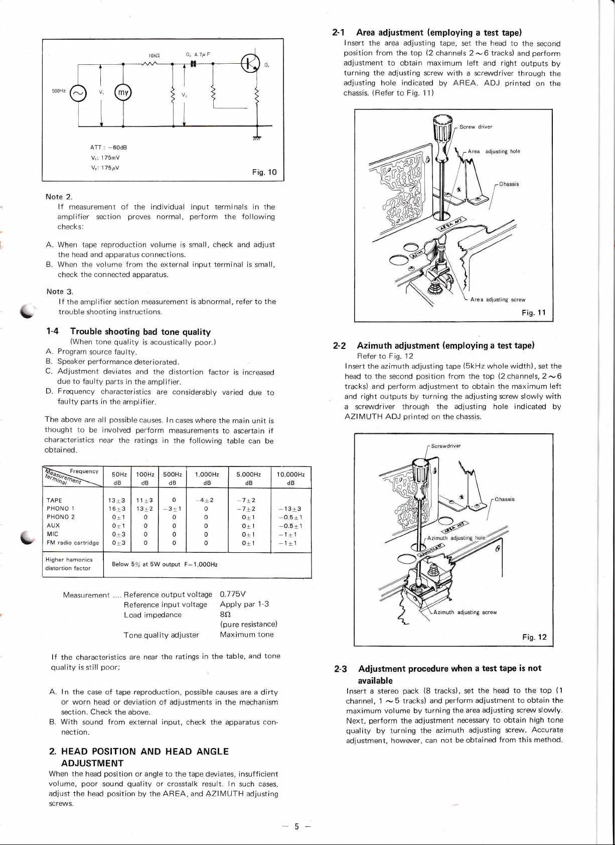
2-1 Area
lnsert
position
adjustment
the area adjusting tape,
from the top
adjustment to
turning the adjusting
adjusting
chassis.
hole
(ReÍer
(employing
(2
channels 2
obtain maximum leÍt
screw with a screwdriver through
indicated
to Fig.
by
1 1)
a test tape)
the
set
-6
and ríght
AREA. ADJ
adlustrng hole
head to
tracks)
printed
the
second
perform
and
outputs by
on
the
the
L
L
A.
When tape
the
D
When the volume Írom the external input terminal is small,
check the
Note
3.
reproduction volume
and apparatus connections.
head
connected
apparatus.
is small,
lf the ampliÍier section measurement
check
and
is abnormal, refer to
trouble shooting i nstructions.
1-4 Trouble
(When
A. Program
B.
Speaker
source
performance
C. Ad.lustment
due to fauity
Frequency
D.
The above
thought
characteristics
obtai
faulty
ned.
parts
are all
to
be involved
k-È{r}-*ï
TAPE
PHONO 1
PHONO
2
AUX
Mlc
FM radio cartridge
Higher
hamonics
distortion Íactor
shooting
quality
tone
faulty-
deteriorated.
deviates
parts
in
the ampliÍier.
characteristics
in
the amplifier.
possible
near the
ratings in the following
OHz
5
dB
13t3
16t3
0:! 1
O+1
Ot3
ot3
Below
sal at 5W output F:1,OOOH,
bad tone
acoustically
is
and the
causes.
perform
1
OOHz
dB
11a3
13
L2
0
0
0
o
quality
poor.)
distortion factor
are
considerably
ln
cases where
measurements
5OOHz
1,OO0Hz
dB
o
4+2
3tl
o
0
o
o
is increased
varied
the main
to ascertain
table
5,OOOHz
dB
o
o
o
0
o
due
can be
dB
7x2
ot1
O+1
Or1
0+'1
adjust
unit
the
to
is
if
1
0,oooHz
dB
13Í3
0.5+ 1
0.5t 1
_1il
1r1
2-2 Azimuth adjustment
Refer to Fig.
lnsert the azimuth adjusting tape
to the second
head
tracks) and
and right outputs by
a
screwdriver
AZIMUTH ADJ
12
perform
through
printed
position
adjustment to obtain the maximum
turning the
on
Area adiusting
(employing
a test
(5kHz
whole width), set the
from the top
adjusting screw slowly with
the adjusting
hole
the chassis.
screw
tape)
(2
channels,
indicated
Fis.
1 í
2
-6
left
by
Measurement ....
lf
characteristics are near
the
quality
is
still
A. ln
the case
BeÍerence output
Reference
Load
impedance
quality
Tone
poor;
tape reproduction,
oÍ
voltage
voltage Apply
input
adiuster
the ratings
possible
in the table,
or worn head or deviation of adjustments in the
section. Check the above.
B. With
2. HEAD POSITION
sound from external input, check the apparatus
nection.
AND HEAD ANGLE
ADJUSTMENT
When the
volume,
the
ad.iust
SCTEWS.
head
poor
head
position
sound
position
or angle to the tape
quality
or crosstalk result. ln
by the AFEA, and
deviates,
AZIMUTH
O.115V
par
8o
(Pure
resistance)
Maximum
and tone
causes are a
mechanism
insufÍicient
such
adjusting
1-3
tone
dirty
con-
cases,
-5-
Adjustment
2-3
available
lnsert a
channel,
maximum
Next,
quality
stereo
1
-
volume
perform
turning
by
ad]ustment, however,
procedure
(8
pack
tracks), set
5 tracks) and
turning
by
the adjustment
the azimuth
can
when
perÍorm
the area
necessary
be obtained
not
Fig.12
tape is not
a test
the
adjustment
ad.iusting screw slowly.
to the top
head
to obtain the
to
obtain high
adjusting screw.
from this method.
(1
tone
Accurate
Page 6

1.
Note
PerÍorm head
position
or
angle
or repair.
Note 2.
Prior to
clean
Accumulated
adjustment
PRESSURE
3.
lmproper
capstan result
quality.
pinch
sure
is required,
oÍ chassis supporter
Note:
the head
the head
pressure
lÍ
in any stereo
roller clean.
mechanism
ad.iust the
The stereo
impossible.
in
adjustment
only
is changed
position or
dipped
a
with
swab
dust may
cause
ADJUSTMENT
adjustment or dirt
wow
Readjustment of
is almost
seen
panel,
pack
Ílutter
and
pack,
wow
completely unnecessary.
pressure by turning
thróugh
facing
cause wow
may
the head
when
the result
as
angle
alcohol'
gain
a
decrease
(neterto
in
and Ílutter
the
the round hole on
the escutcheon.
and
oÍ
adjustment,
or make
Flg 13)
the inch roller
on
addition
arises, wipe
MODEL ts'E2O2pres-
Ílutter.
installation
replacement
thoroughly
perÍect
poor
to
lÍ adjustment
the derlin
the
right side
and
tone
the
nut
Lessen
Escutchon'
pressure
lncrease
Chassis support
D rivor
pressure
panel
\
]
L
pressure
Pack
adiustrng
screw
hole
Fis. 13
*TROUBLE
(ReÍer
to circuit diagrams,
Trouble Defective circuit
No sound.
Reproduced'
sound weak.
High
tones
not
reproduced.
tones
Low
not
reproduce.
SHOOÏING
Power
supply circuit.
circuit
Output
Pre-amplifier
driver stage.
Equalizer
Microphone circuite
Switch
Driver stage and
output circuit
Equalizer
microphone
Equalizer
Equalizer circuit
circuited
circuit
and
circuit
INSTRUCTIONS:
printed
circuit boards and assembly diagrams)
and
circuits
.
Rectifier
.
The
(008-0613-01
o
Faulty contact
o
Ctos, C364 and C3g7 short circuited.
.
Speaker
.
Output transistor Ots, Oro, O17
circu
.
R32, Rrs,
r
05, 06, Ot,
I
Crr, Ctz,Cr:,Cra, Cts, Cro,Crrt,Crrz,Crr:, C114,C115 and
C116 open or short circuited.
I
R:o? and R36g open
r
Or, Oz,
o
Cr,Cz, Ca, Ce, Cs, C9, C361, Caoz, Ctor, Croz, Cror, Cro+,
and R199 open or short circuited.
o
Rao2 and R364
.
O19 open or
o
C+01,
R4o8 oPen.
'
r
Faulty
1
Cn,Crq,
.
Rt9, Rrtg,
varied.
o
Os, Oo, Ot, Oa, Oq, Oro, Orr, Orz, O13
o
C:, Cros and C463
o
Rz, Rroz, Fi461
o
Or, Oz, O3, 04 and O19 deteriorated.
.
Poor reproducing
a
Faulty adjustment
a
Reproducing head
o
Cs, Co, Cz,
o
RZ, Ra,
leaking.
(001-0072-00,
primary
voice
ited.
Rrr and
03 and 04 open or short circuited.
Cqoz,Ccotand C464 opàn o, short
switch contact,
Crc, Cro, Crl.+ and C116,
Bs, RrO, RrOo, Rror, Rros, Rtro, Ra, Rao and R136
DeÍect and cause
0O1-007 1-00)
and
secondary side of
is
open.
)
power
with
coil open.
OA, 09 and O16 open or short
open or short circuited.
short
RZr, RZZ, ROt, RnZ, RZO and R126
and
head sensitivity
Cros, C166
supply switch
R132
oPen.
short circuited.
or
circuited.
leaking
capacity.
R4o2 resistance value varied.
reproducing
of
(01
1-021
1-001 worn.
and
C167
open.
power
supply
(013-3027-00).
O1g
and
open
circuited.
circuited.
leaking
capacitance.
O14 deteriorated.
and
(01
head
leaking capacitance.
1-021
lO11-O21
1-00)
transformer
or short
resistance
1-0O) azimuth.
Croa
value
Corrective action
Replace
Replace
Replace
Replace
Replace
Replace
Replace
Replace
Replace
Replace
Replace
Replace
Replace
Replace
Replace
Replace
Replace
Replace
Replace
Replace
Replace
Replace
Replace
replace
or
Clean
Readiust
Replace
Replace
Replace
\
§
-6
Page 7

Trouble Defective
Driver circuit
is
Sound
distorted.
Equalizer and
microphone
circu its
Power
Oscillate.
Driver stage and
output circuit
Equalizer circuit
(
Head
switching
impossible.
sound
No
'
the
in
radio
pack.
Plunger circuit
Power supply
or
connecting
circu
supply
it
Circuit
circuit
circuit
Defect
.
Orr,
Orz, Or:, Or+, Ors, Ore
pairing.
o
D1, D2, Dt,Dc,
o
Semi-fixed resistor
resistance varied or
o
Rr7,
RrS, RZO. Rza, RZs, RZO, Rtn,
and R126 open.
.
Crt and C117
r
Or, Oz, 03, Oa and Q19 deteriorated.
o
R2,R4,
o
Cz, Ct,
Cs,
leaking capacitance,
a
C:or,
Caoz, Caor,
a
Raot,
RtoZ, Raos,
resistance varied.
r
R36
and
.
Cre and C113 leaking
o
Reproducing head connecting
.
.
.
o
o Plunger
o
.
o
r
ixed resistor
Semi-f
and
C+
C164
Faulty contact or defective mechanism
(960-2657{O).
switch
silicon diode short circuited.
Q
(015-O14O-O2)
Cloz short
Plunger
Cgoz short circuited.
Faulty connector
pin.
bent
D5 and D6 deteriorated.
2-3249-AO-Íor balance adiustment
O1
2-325o-00-Íor non-signal current adjustment.
01
ad.justment deviates.
leaking capacitance.
Rro, Rroz,
Rrle
circuited.
(015-0140-02)
Rro+,
Cs, Croz. Cror, Croa,
Cao+, C.365 and C462
Rso+, Rros, Raoo, ReOz, BaOa and
oPen.
capacitance,
(for
gain
leaking capacitance.
coil layer short
coil
pin
contact
Rrro,
adjustment)defective.
layer
Orz
and O1s defective or
,
Rrtq, Rzzo, R123, R126,
R4s1 and R4os open.
Crog, C+ot, C+or and C4s4
leaking capacitance.
(010-1631-00)
lead
in the channel
circuited.
circuited.
short
(074-0400-00)
to a broken
due
R4s6
defective.
changeover
faulty
Correction
Beplace
Replace
Readiust
replace
Replace
R125
or
Replace
Replace
Replace
Replace
Replace
Replace
Replace
Replace
Replace
Beplace
Replace
Replace
Replace
Beplace
Replace
Replace
Replace
Beplace
Repair
replace
or
e
-7
Page 8

EXPLODED
*
VIEW
(See
parts
list,
Grey
portion
disignàte assemblies)
A-
/ \ï,\
N
l" )')@m.,
\JJ
7-
:-eu»
-oD
N
%"=
(\\
\\___:
o
u
Yn-l
=Q
Ug
=8'
!
-8-
Page 9

+re'ue,
ó
,rt
102
sg
o978
-9-
Page 10

u
ly
-
t0
Page 11

f
PARTS
*
(Parts
circled in
REF
Nro
380-3265
2
380-32
a
122-021A
4
371 2267 00
5
37
6 314-27
371 2264 00
8
3t 5-0411-00 Pilot
I 375
10
375-0473-00 Pilot decoration
11
315-0414
12
31 1
g2M3x6
14
+2M26x6
'1
5 330
16 750-0830
17
34 1
i8
320 01 52 00
19
382 0050 00 B utton
20
750-1241
21 M4x?5
22
74
23
34
24
319 0001-00 Cabinet
25 303 024 1
z6 311 2266-01
21
008-061 3-0
2B M3xO.5x6
29
M3r0
30
07 3-02 5-000 Terminal
31
330-4679 01
32
M3x0
33 7 22-019,OOO
34 745-03 1
35
01 3-301 9-00 Power
36 330 4685-00
3l 312
38
281 1175-00
39
287 1111-00
40
330-4683 00
41
073-C421-00
4?
o42-O102-00
43
099
44
1
20-001 -000
45
013-O422-O0
46
*
47
825
48
01 7-003
49
070-08s6 01
50 330 4680-00
51 09 9-3
52 M3x0.5x10
FO
M3
LIST:
gray
PART
01
66-01
Refer to disassembly
are assembly.)
NO
B knob
knob 55
A
diagrams,
DESC RI
PTI O N P,C,S
00 Nut 2
plate
Trim
5-047 5-00 Pilot
43-00 Esc
decoratron 1 5B
utc h eon
plate
Trim
decoration 1 61
0412 00
Pilot
decoratLon
00 Pillot decoration
-2265-00
4653 00
-005
9-00
00 S
00 S
p
Trim
ate
Tapping
Tapping
screw
screw
Hold Íittrng
prin g
ShaÍt 1
prooÍ
Dust
prin g
cover 1
Machine screw
5-046 3-00 Flat washer
5-22 9 6-00 Bubber
-00
1 Power supply transÍormer
base 4
Top half
Top
oÍ case
p
ate
Machine screw
5x8 I\zlachine
Hold
5x6 Machine
Hexagon
-000
Washer
screw
plate
screw
nut
switch
Power
switch
mounting
0131 01 Chassis
plate
Name
plat-^
Name
Lead hold
Íitting
Terminal
3946-01
r-J
002-001
Electrotytic
Printed circuit board
lPourar <ant,nn\
IA
Term in
Flat washer
Shading
capacitor 1
fLrse
al
(f
1
3) 15
tube
002 Pilot lamp
945-01
Pilot lamp
Circuit board
Printed
(Amolifier
Machine
Toothed
socket
circuit
secTlon)
screw
washer
hold f itting
board
(M3
x
photographs,
plate
(A)
0.5
1O)
x
printed
circuit board diagrams
REF
54
4
56 340-03 3 1
1
51 3'1 3-0790-00
,1
59 012-3254 0A
1
60 01 2-3253-00
62 330-46 B2-00
1
C'J
64
1
65 850,1
1
66 M3x0.5x6
2
67 281-117 6-00
2 68 286-3511-OO
2
69 073 0420-00 Termin a I
lo 073-04 1
11
,]
l2 3 1 2-01 30,00
1 13
4 74
4
15 745-03 1
16 M3x05x35
1
11 M3x0.5x4
,]
18
1
19 321 074?02 Flexible lead holder
1
80
4
81 71
2
2
B3 M2 6xB
1
84 01 1
39 85 630-024G 0 1
4
86 750 1 1
4
B7 632-01 42
1 BB
1
B9 M3x0.5x14
1
90 M3x0.5x8
1
91 630-0238
1 92 750-1197 01
1
,]
94
95 M2x 4
1 96
2
97 013218000
4
98
99 632-01 26-00
,l
100
101 750-1 1 69-01
5
1
102 M3x0.5x25
,l
103
,]
104 01 3-3028-00
10
105
2 106
PART
+2N13x0
1 46-441-AOO
-00
2
a1
3251 00
01 3 3020 00
012 3252 01
09 9,3 944-0
842 00
9- 00 Term in a I
074-004
9-00
722-424-000
-000
+23
1'3
#
6 01 81-00 Area
-021
1-
8&01
154 1231 01
1
0
40-02
5-01
634-0242
M3x0.5x6
043-0022-00
347
3s03 00-
330-4686-00
and circuit
NO DESC RIPTIO
5
Hexagon
lnsu
Spacer 3
Heat sink
Variabie resistor
Variable resrstor
/Ínr MIC v.l,,mc .ónÍrol\
Variable reststor
/Í^r
Botary switch
Circuit
Variable resistor
1
Head relay
Powe r
Machine screw
Name
Set
Chassis
AC receptacle
Hexagon nu1
Washer
Machine screw
Machine screw
Spring
Flat washer
Machrne screw
00
Reproducing head
Head
Set spring
A1 Collar
Balance
,Azrmuth
Machine
01 Balance
Adjust
Plunger 1
Mach ne
Spring washer
Hotary
(íor
01 Rotary switch mount f itt ng
Botary switch mounting screw
Machine screw
Raehet spring
Machrne screw
Cerarn
Microswitch
Insuiatlnq
Deek hold f inrng
diagrams
N
(*2)
nut
washer
ating
(for
tone control)
-A
^-)-^^ó
(for
selection)
hold Íitt ng
board
prrnted
lead 1
(B)
(for
volume control 1
ciicuit board
(M3
0.5 x 6)
x
plate
plate
(M310.5
(M3
35)
x
4)
0.5
x
r
washer
adjustino screw
(M2.6xB)
holder
shaft sprrng
adl usting screw
(M3x0.5xB)
screw
plate 1
spring
(M2
screw
swrtch
channel switching)
c capacitor
4) 2
/
(S2
2) 2
(M3x0.5r
(M3
y0.5 y
6) 2
25) 2
(CK) 1
paper
(B) 1
Dac
6
4
1
1
1
1
1
1
,l
2
1
1
2
1
1
1
1
l
1
1
2
2
-il-
Page 12

REF.
101
108
109
110
111
112
113
115 750-1243
116
117
't
i8
119
120
121
122
I ZÓ
124
125
127
128
130
1
3"1
132
133
134
136
137
138
139
140
141
142
143
144
145
146
147
148
149
150
151
152
154
1trE
PART NO
M3x0.5x8
073
0230-00
M3x0.5x8
630-0389-00
M2.6
6
x
M2.6
x 8
632-O124-00
00
074-0400-00
605 00'l 2-0.1 Tape
63 1 -0044-00
3 3 5-058 5-00
611-00'1 4-00
M3x0.5x10
M3x0.5x10
360-3
6 5-000 S lide
630-0388-00
750-1242-00
360-898 1
360-9 1
6 3 1
00 Pressure
5-200 Pressure
-0046-00
630-0396-00
345-22 I 8,00
-1
36 1
33-000
M3x0.5x14
M3x0.5x6
630-03
97-00
607-001 2-00
N/5
630-0373-02
070-089
7-00 Pilot
345-2297-OO
-000
07 5-00 1
075-0080
073-0220
00
00
360-35 9-000
603-001
9-00
M2.6x4
-01
021
33-00
631
0047-00
145-O464-00
M4x0.7x'1 0
330-46
84-00
156
157
vL
w25V1
000rF Electrolytic
158
159
vl-w16V1
032-0001
000rF Electrolytic
-00
DESCRIPTION
Machrne
1L2P
lugrterminal
Machrne
(Sems
type M3xO.5x8)
plate
Base
Machine
Machine screw
sc'ew
screw
screw
(M3x
0.5
(M2.6x6)
(M2.6x8)
8,1
x
Sleeve
pring
S
Connector
prn
guide
cap
Lead holder
Flywheel
screw
(M3x0.5>'1
(M3
0.5
x
(B)
0)
10)
x
Machine screw
Machine
bushing
Stop lever
g
Sprin
spring
adjusting washer
plate
Guide
(2)
Plate
G romm el
Lock nul
Hressure
(M3>
Machine
-Housing
Housr ng 1
E
End
adiusttno
O.5x 14)
screw
plate
retaining nng
plate
lamp
socket
screw
(M3xO.5x6)
Pilot holder
Microphone
Head
1 L4P
Flat
Motor
phone
lug terminal
belt
pulley
socket
socket
Set screw
AC
l\,4otor
Collar
Washer
Machine
Deck hold fitting
Hole
cap
Wood
screw
Wound resistor
screw
ca
ca
(M4x0.7x
(A)
pacitor
pacitor
(1WO.41
10)
+
1
A
A%)
REF
P.C,S
14
160
2
161
162
1
163
164
165
1
166
,l
167 vl-w5ov'trF
1 168
.1
170 25C132
111
172
114
115
2
176 012-112-OOO
177
118
119
1
6
1
1
1
1
1
1
,]
1
1
,l
1
1
1
1
1
3
3
I
1
,l
2
3
1
4
PART NO, DESC RI PTIO N
25D235
or 2SC1061
2SC735
or 2SC984 Silicon transisïor
2S4526
or 25,4565
vl-w2
5V1
0'1 2-3250-00
012-3249
MB513,A
HV-26
2SC373
or 2SC458L
69 vl-wi
ov.t 00rF Electrolytic
or 2SC458L
vl-w10v10rF
vL
w6 3V220rF
vl-w6.3V33rF
vl-w10v47rF
vl-w1
0v220rF Electrolytrc
vlw16V4.1
54V0.04
uF + 20oÀ Polyester
50V0 15pF
50V50OPF
2Ma+10%
%\,N1
,NU82a+1O%
t/zw1Ka+10%
1ÀW33a+1j%ELR
1AN100O+14%ELR
W120O+1j%EtR
tNVz2Oa+1)%ELR
W470aiIj%ELR
t/^N56Oa+1O%ELR
%WB20a+1j%ELR
W1Kai1j%ELR
W1.2Ka+10%ítR
W1.sKa+1O%E:R
\ÀN2.2Ka+1j%ELR
1,4N3
SKA+1j%ELR
W4.7KO+1jo/óElR
aÀN\.6Ka+1j%ELR
1ÀN8.2KO+1)%?LR
\À
t12Ka+1j%ELR
W22Ka+1O%ELR
aÀN33KA+1O%EIR
W47Ka+1j%EtR
W1OjKat1O%ELR
Y&\'l15OKa+1j%ÉLR
aÀW1?1Ka+1j%ELR
090-01 91 00
090-01
92-00 Speaker
3 1
6-0382-00
311 226?-0A
-1
11 4-04
281
07 4-O442-OO
output silicon transistor
Srlicon transistor 2
F
00r
Electrolytic
Semi-Íixed resistor
00
or HV-23
SemiJixed
Diode
Electrolytic
Silicon transistor 2
Silicon transistor 1
Electrolytic
Electrolytic
Electrolytic
Electrolytic
Semi-fixed resistor
pt Électrolytic
+20% Polyester
+20% Polyester
Solid
Solid resistor
Solid resistor 1
Film resistor
Film resistor
Film resistor
Film resistor
Film resistor
Film resistor
Film resistor
Film resistor ?
Film resistor
Film resrstor
Fiim resistor
Film resistor
Film
Film resistor
Film resistor 4
Film resistor
Film
Film resistor
Film resistor
Film resistor
Film resistor A
Film resistor 2
Speaker
Speaker case
Trim
Name
Termrnal
Speaker
capacitor
(25Vl
00lF) 2
(500OB)
(30K8)
resistor
capacitor
capacitor
capacitor
(50V1lF)
(1
0V1
OOtF)
1
0v1 OrF)
capacrtoí 6.3V22OPt) 2
capacitor 6.3V3 3rF)
pacitor
ca
1OV47
capacrtor 10v220pF)
(1
0KB) 2
capacitor
(1
4.7
6V
capacitor 2
capacitor
capacitor
resistor
resistor
resistor
(Íor
low
tone)
(for
high tone)
olëte
pl61s
plate
grrlle
P,C.S
4
4
2
2
6
4
2
I
1
pF) 3
1
pF) 2
2
2
1
7
2
5
2
4
2
4
3
2
3
6
3
5
8
1
4
4
2
5
-
12-
Page 13

fr
PRTNTED
*
CtRCUtT
BOARD
COMPONENT
VIEW
(}'
-
t3
-
Page 14

*
PRINÏED
.9
o6
CIRCUIT
00 9€0e
BOARD
I
€i0
I
;
Y, @
!;
às
@i
:r
R
t
!
Ë
E
&9
öali
0I
;;;;
6*".]b-
ö
ll
5m@ooo
li
6 _-
ommooo
x
9
E
6
r
ó
F
E
oë
oa
o
6
E
I
t4-
-
c;
Ro
9*
-8
a
Page 15

L
*
CIRCUIT
rnd .Lno
09q sz2r 00t
I
00 1000
qz qL
aB)§
DIAGRNM:
=
s
zeo
v0[
6YZt Zt0
9
o'^
r
=00
3=
i-
$71n
NtE
"i3
I
rG
j?
loö'loero
ÈÈ
lJ-s
rzo
.
--
§§
?
E
sl-
_
--_l
I
I
o
o
o
o
ó>
-N
QN
N
;
q
;=
Í .ö
0'6
x
í Èe
qE
u
À
ËE
?;
099
9ZIU
3 f
!U
*z
o
=
00I Ez
9l1J
L
Ëg
8r
EË
r
a
rr00_-0rc
iH
o
EI
(
a
a
=
i
"\
j
o!9
a
a
t5
-
-
Page 16

Voltage
'È
and current
OO
OO
@a
NN
rO
o
N
O
a
Ë(
N
values
entered.
(O
o@
oo
ÓO
aa
NN
E
N
T
r
N
o
rr)
cÍ)
o
o@
N.O
(JO
a@
NN
O)
o
OO
aa
NN
N@
OO
a@
NN
OO
@a
NË3
É.8
OKK
q
t
l
o
\*
)
o
E
E
o
E
c
c
.g
:
o
f
t
5
J
t
É
a
:t
o
__
ï 9 - u>
Nó : N
s§
OO
aa
o)
o@
LO
oro
Eoou
cocc
J
;ji
ooó
a=a4
t!OU
!_,
P
dr m:!
=öó-
!'-
!P
-3è.
c
F,
É
O o È {
=
o
o
9-o
U
óA
o
Gi
-
q>
o
NO
o
3r
\
I
i
o
ÓN
!
N@
o
OO
ó@
NN
o
J
t6
-
-
 Loading...