

Page 1
clariori
Owner's manual
Mode
d'emploi
Manual de instrucciones
DXZ6SSMP
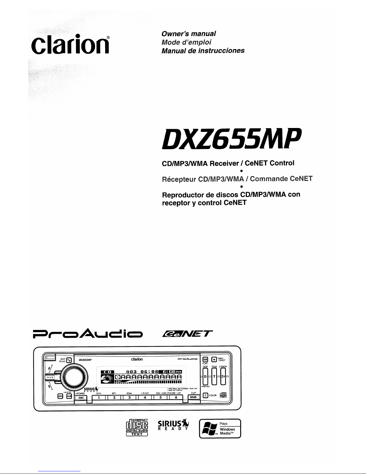
CD/MP3IWMA Receiver I CeNET Control
•
He~Ce[~telJr
CD/MP3IWMA I Commande CeNET
•
Reproductor de discos CD/MP3IWMA con
receptor
y control CeNET
82!lTNET
rillo
O
§rn3
DIGITAL
AUDIO
~
SIRIUsiM
REA
0 Y
Page 2
I
Thank you for purchasing this Clarion product.
*Please read this owner's manual in its entirety before operating this equipment.
*After reading this manual,
be
sure to keep itina handy place (e.g.) glove compartment).
*Check the contents of the enclosed warranty card and keep it carefully with this manuaL
*This manual includes the operating procedures of the
CD
changer, SIRIUS and TV tuner
connected via the CeNET cable. The CD changer and TV tuner have their own manuals, but no
explanations for operating them are described.
Contents
1. FEATURES 2
2. PRECAUTIONS 3
Motorized Face 4
Handling Compact Discs ,
4
3. CONTROLS 5
4. NOMENCLATURE 6
Names of the Buttons and their Functions 6
Major button operations when external equipment is connected to this unit 7
Display Items
8
LCD Screen 8
5. DCP 9
6. REMOTE CONTROL 10
Inserting
the
Battery 10
Functions of Remote Control Unit Buttons
11
7. OPERATIONS 12
Basic Operations 12
Radio Operations
'"
15
CD/MP3IWMA Operations 16
Operations Common to Each Mode 20
8. OPERATIONS OF ACCESSORIES 24
CD Changer Operations 24
TV Operations 25
9.
IN
CASE OF DIFFICULTY 26
10. ERROR DISPLAYS 27
11. SPECIFICATIONS 28
• Full-Dot, High-Contrast Positive Display With Eye-Catching Graphics
• 728 Variable Colors (Display/Function
Key)
• MP3 and WMA Playback With ID3-TAG and WMA-TAG Display Capability
• High-Powered Internal MOSFET Amplifier (53 Watts x 4 Channels)
• 6-Channel RCA Output for Easy System Expansion
• Auxiliary Input for External Device Connection
• Sound Enhancing 2-Band Parametric
EO
/ Z-Enhancer Plus / Magna Bass
EX
• Motorized Sloping Faceplate for CD Loading
• Detachable Aluminum Faceplate
2
DXZ655MP
Page 3
1.
When the inside of the car is very cold and the
player is used soon after switching on the
heater moisture may form on the disc or the
optical parts of the player and proper playback
may not be possible. If moisture forms on the
disc, wipe it off with a soft cloth. If moisture
forms on the optical parts of the player, do not
use the player for about one hour. The
condensation will disappear naturally allowing
normal operation.
2.
Driving on extremely bumpy roads which
cause severe vibration may cause the sound
to skip.
3. This unit uses a precision mechanism. Even
in
the event that trouble arises, never open
the case, disassemble the unit, or lubricate
the rotating parts.
I
This equipment has been tested and found to
comply with the limits for a Class B digital device,
pursuant to Part 15 of the FCC Rules.
These limits are designed to provide reasonable
protection against harmful interference in a
residential installation.
This equipment generates, uses, and can radiate
radio frequency energy and, if not installed and
used in accordance with the instructions, may
cause harmful interference to radio
communications. However, there is no guarantee
that interference will not occur
in
a particular
installation.
If this equipment does cause harmful interference
to radio or television reception, which can be
determined by turning the equipment off and on,
the user is encouraged to consult the dealer or
an experienced radiolTV te?hnician for help.
USE
OF
CONTROLS,
ADJUSTMENTS,
OR
PERFORMANCE
OF
PROCEDURES OTHER
THAN
THOSE
SPECIFIED HEREIN, MAY
RESULT IN
HAZARDOUS
RADIATION
EXPOSURE.
THE
COMPACT
DISC
PLAYER
and
MINI DISC
PLAYER
SHOULD
NOT
SE
ADJUSTED
OR
REPAIRED
BY
ANYONE
EXCEPT
PROPERLY
QUALIFIED
SERVICE
PERSONNEL.
CHANGES OR MODIFICATIONS NOT
EXPRESSLY APPROVED
BY
THE
MANUFACTURER FOR COMPLIANCE COULD
VOID THE USER'S AUTHORITY TO OPERATE
THE EQUIPMENT.
IlWit·]jll,tiit·Ulit·]j'lki#j;iI
CHANGES
OR
MODIFICATIONS TO THIS
PRODUCT
NOT
APPROVED
BY
THE
MANUFACTURER
WILL
VOID
THE
WARRANTY
AND
WILL
VIOLATE FCC
APPROVAL.
MODEL
I
Iclarion
12V 8 GROUND
AM 530-1710kHz/FM 87.9-107.9MHz
THIS OEVICE COMPLIES WITH PART15OF
THE FCC RULES,
OPERATION
is
SUBJECT TO THE FOLLOWING TWO CONDITIONS.
(1) THIS DEVICE MAY NOT CAUSE HARMFUL INTERFERENCE,
AND
(2) THIS OEViCE MUST ACCEPT ANY INTERFERENCE RECEIVED
INCLUDING INTERFERENCE THAT MAY CAUSE UNDESIRED
OPERATION.
THIS
PRODUCTION
COMPLIES
WITH
DHHS
RULES21CFR
SUBCHAPTER
J APPLICABLE AT DATE OF
MANUfACTURE.
CLARION
CO"L
TO.
50 KAMITODA,TODA·SHI,SAITAMA-KEN,JAPAN
This product includes technology owned by
Microsoft CorporaMn and cannot
be
used or distributed
without a license from MSLGP.
MANUFACTURED:
Bottom
ViewofSource
Unit
SERIAL
No.
PE~
286-e=:J
ClartonCa.,Ltd.
MADE
INc:::::J
DXZ655MP
3
Page 4
Motorized Face
This unit uses motorized face to make large-screen displays possible.
When you use the motorized face, be sure to close it.
3.
If you move the MOTORIZED FACE by hand,
this may create play.
To
correct this
play,
with
the power on for the unit, press the
[~]
button to close the MOTORIZED FACE.
4.
After a disc is ejected, the MOTORIZED
FACE automatically returns to the tilted or
closed state. If there is any obstruction when
the MOTORIZED FACE tries to close, the
safety mechanism is triggered and the
MOTORIZED FACE returns to the open state.
If this happens, remove the obstruction, then
press the
[~]
button.
5.
To
avoid scratching the compact disk, keep
the 12 or 8 cm CD level when inserting or
removing them.
BE CAREFUL NOTTO GET YOUR FINGERS
CAUGHT WHEN OPENING AND CLOSING
THE MOTORIZED FACE.
1.
For safety's sake, always close the
MOTORIZED FACE before leaving this unit
unused for a prolonged period or switching
OFF the ignition
key.
If you switch OFF the ignition key with the
MOTORIZED FACE tilted, the MOTORIZED
FACE does not close.
2. Before the MOTORIZED FACE closes, there
may be a braking sound from the safety
mechanism. This is normal.
Handling Compact Discs
•
Do
not use compact discs that have large
scratches, are misshapen, cracked, etc.
Use
of
such discs may cause misoperation or damage.
•Toremove a compact disc from its storage case,
press down
on
the center of the case and lift the
disc out, holding it carefully by the edges.
• Do not use commercially available CD
protection sheets or discs equipped with
stabilizers, etc. These may damage the disc or
cause breakdown of the internal mechanism.
Storage
• Do not expose compact discs to direct sunlight
or any heat source.
• Do not expose compact discs to excess
humidity or dust.
• Do not expose compact discs to direct heat
from heaters.
Cleaning
•Toremove fingermarks and dust, use a soft
cloth and wipe in a straight line from the center
of the compact disc to the circumference.
• Do not use any solvents, such as commercially
available cleaners, anti-static spray, or thinner
to clean compact discs.
• After using special compact disc cleaner, let
the compact disc dry off well before playing it.
Use only compact discs bearing the
[Q]m~©
or
rDlCOMPACT DIGITAL AUDID
r~i~
mark.
Do not play heart-shaped, octagonal, or other
specially shaped compact discs.
Some CDs recorded
in
CD-R/CD-RW mode
may not be usable.
Handling
• Compared to ordinary music
CDs,
CD-R and
CD-RW discs are both easily affected
by
high
temperature and humidity
and
some of CD-R
and CD-RW discs may not
be
played. Therefore,
do
not leave them for a long timeinthe
car.
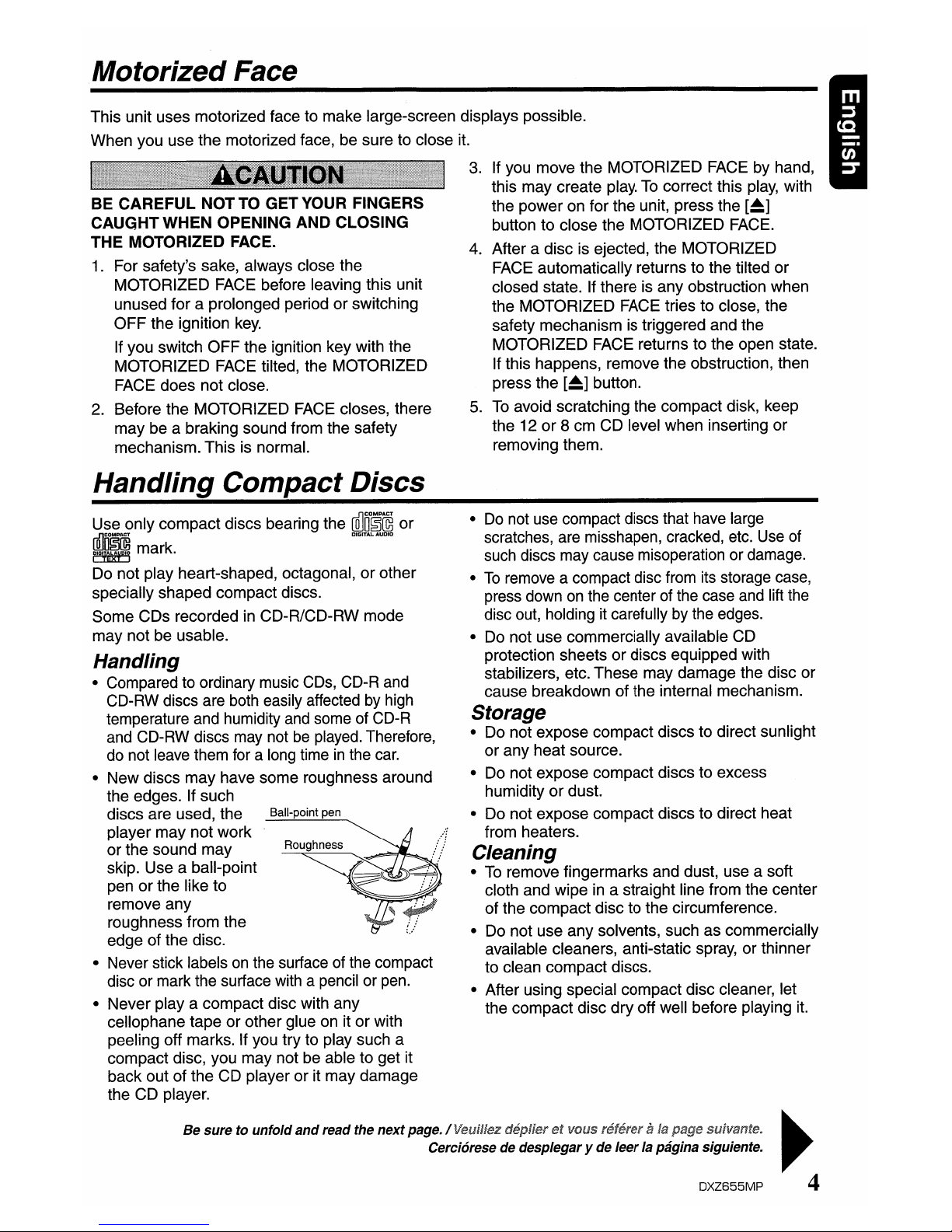
• New discs may have some roughness around
the edges. If such
discs are used, the
Ball-point pen
player may not work
or the sound may
Roughness
skip. Use a ball-point
pen or the like to
remove any
roughness from the
edge of the disc.
• Never stick labels
on
the surface of the compact
disc or mark the surface with a pencil or
pen.
• Never
playa
compact disc with any
cellophane tape or other glue on it or with
peeling off marks. If you try to play such a
compact disc, you may not be able to get it
back out of the CD player or it may damage
the CD player.
Be sure to unfold
and
read the nextpage./Veuilfez deplier
et
VOIIS referera
fa
pagesuivante.
....
Cereiarese de desplegary de
leer
la pagina siguiente.
,..
DXZ655MP
4
Page 5
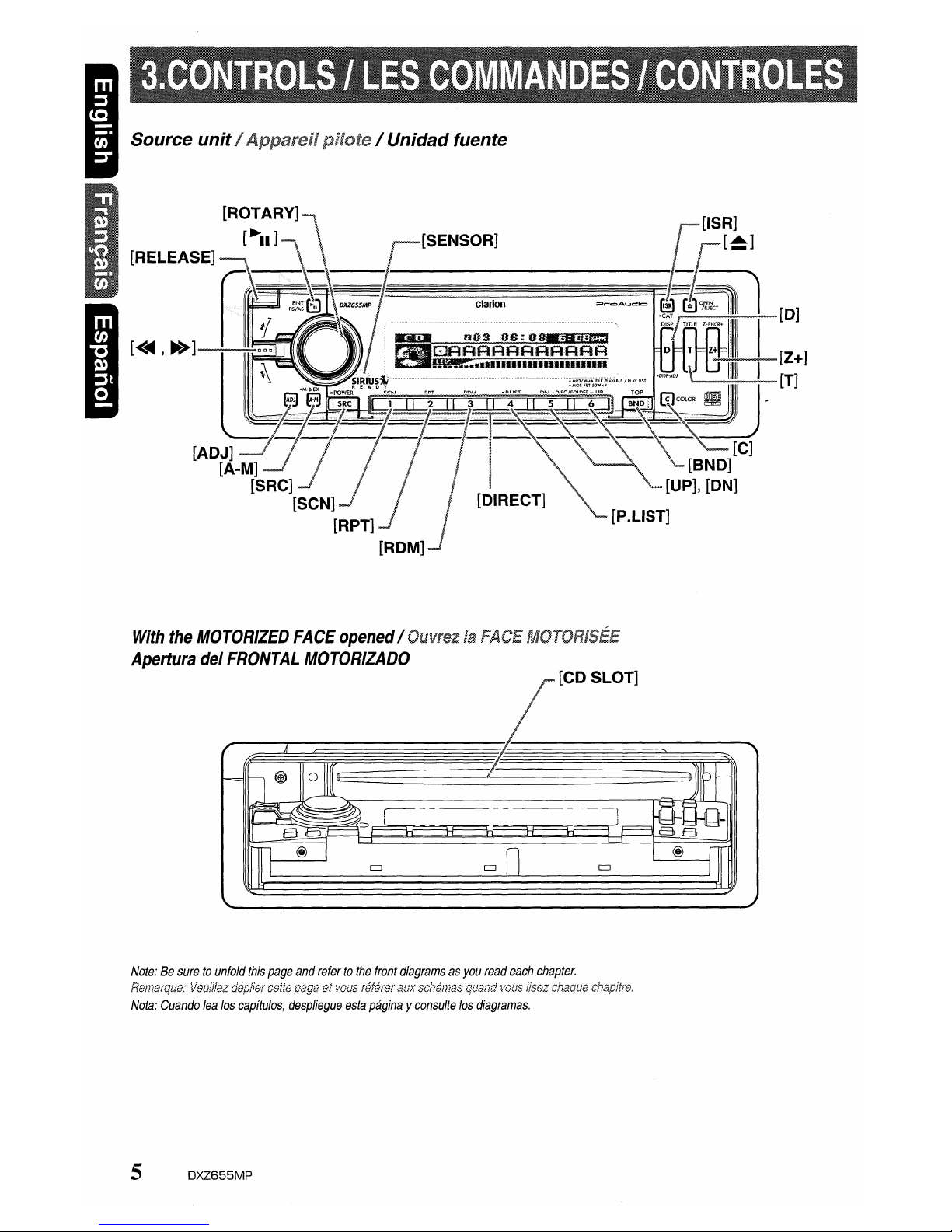
Source unitI Apparel! / Unidad fuente
......------.;,,;.~-[D]
~--o..-[Z+]
~~~[T]
With
the
MOTORIZED
FACE
opened/OuvrezlaFACE
Apertura
del
FRONTAL
MOTORIZADO
[CD SLOT]
Note:Besuretounfold
this
page
and
refertothe
front
diagramsasyou
read
each
chapter.
Remarqua:
l/euff/ez
deplier
cette
pageatvaus
referer
aux
schemas
quand
vaus
lisez
chaque
chapitre.
Nota:
Cuando
lea
los
capftulos,
despliegue
esta
paginayconsulte
los
diagramas.
5
DXZ655MP
Page 6
Note:
• Be sure to read this chapter referring to the front diagramsofchapter
"3.
CONTROLS" on page 5 (unfold).
Names
of
the Buttons
and
their Functions
[RELEASE] button
• Deeply pushinthe button to unlock the
DCP.
[
"II]
button
• Perform preset scan whileinthe radio mode.
When the button is pressed and held, auto
store is performed.
• Play or pause a CD while
in
the CD/MP31
WMAmode.
[ROTARY] knob
• Adjust the volume by turning the knob
clockwise or counterclockwise.
• Use the knob to perform various settings.
[SENSOR]
• Receiver for remote control unit
• Operating range: 30°
in
all directions
[ISR] button
•
RecalliSR
radio stationinmemory.
• Press and hold for 2 seconds or longer: Store
current station into ISR memory (radio mode
only).
[~]
button
• Press to eject a CD loadedinthe unit.
• Press to open the CD slot and insert a CD.
[0]
button
• Switch the display indication (Main display,
Sub display and Title display).
• Press and hold the button for 1 second or
longer to enter the display adjust mode.
[Z+] button
• Use the button to select one of the 4 types of
sound characteristics already stored
in
memory.
[T] button
• Use the button to input a titleinthe radio, CD
mode.
• Use the button to switch the user titles or
track titles, while
in
the CD/MP3IWMA mode.
• Use the button to scroll the title during the
CD-text play, while
in
the CD/MP3IWMA
mode.
[C] button
• Button's color change to multicolor.
[BND] button
• Switch the band, or seek tuning or manual
tuning while
in
the radio mode.
•
Playa
first track whileinthe CD/MP3IWMA
mode.
• Press the button to change the character.
6
DXZ655MP
[UP], [ON] buttons
• Select the folder whileinthe MP3IWMA mode.
[P.LIST] button
• Press and hold for 1 second or longer to turn
on
or off the play list mode. (MP3/WMA disc only)
[DIRECT] buttons
• Store a station into memory or recall it
directly while
in
the radio mode.
[ROM] button
• Perform random play whileinthe
CD/MP31
WMAmode.
• Press and hold the button for 1 second or
longer to perform folder random play while
in
the MP3IWMA mode.
[RPT] button
• Repeat play whileinthe CD/MP3IWMA mode.
• Press and hold the button for 1 second or
longer to perform folder repeat play while
in
the MP3IWMA mode.
[SCN] button
• Perform scan play for 10 seconds of each
track while
in
the CD/MP3IWMA mode.
• Press and hold the button for 1 second or
longer to perform folder scan play while
in
the
MP3IWMA mode.
[SRC] button
• Press the button to turn on the power.
Press and hold the button for 1 second or
longer to turn off the power.
• Switch the operation mode among the radio
mode, etc.
[A-M] button
• Use the button to switch to the audio mode
(sub-woof vol, bass, treble, balance, fader, ZEnhancer Plus)
• Press and hold for 1 second or longer to turn
on or off the MAGNA BASS EXTEND mode.
[ADJ] button
• Press the button to enter the adjust mode.
[<...-,
~>]
lever
• Select a station while in the radio mode or
select a track when listening to a
CD.
This
lever is used to make various settings.
• Press the lever upward or downward and hold
in
position for 1 second or longer to enter the
fast-forward or fast-backward mode.
[CD SLOT]
• CD insertion slot.
Page 7
Major button operations when external equipmentis
connected
to this unit
_ When the CD/DVD changer
is
connected
* For details, see the section "CD Changer
Operations". For the DVD changer, refer
to
the Owner's Manual provided with the
DVD changer.
[
~II]
button
• Playorpause a
CDorDVD.
[0]
button
• Press the button to display the title.
• Press and hold the button for, 1 second
or
longer to
enter
the display adjust mode.
[T] button
• Press the button switches the usertitles
or
track titles, etc. whileinthe CD changer mode.
• Use the button to input a title
in
the CD
changer mode.
• Use the button to scroll the title during CDtext play.
[BND] button
• Move the next disc in increasing order.
[UP], [ON] buttons
• Select the disc.
[ROM] button
• Perform random
play.
Also perform disc ran-
dom play when the button is pressed and held.
[RPT] button
• Perform repeat
play.
When this button
is
pressed and held, disc repeat play is performed.
[SCN] button
• Perform scan play'for 10 seconds of each
track. Disc
scan
play is performed when the
button is pressed and held.
[<~,
~>]
lever
• Select a
track
when listeningtoa disc.
• Press the lever upward or downward and hold
in
position for 1 second or longer to enter the
fast-forward
or
fast-backward mode.
_ When the TVisconnected
* For details, see the section
'TV
Operations".
[
~II]
button
• Perform preset scan while in theTVmode.
When the button is pressed and held, auto
store is performed.
[BND] button
• Switch the band.
• When the button is pressed and held, switch
seek tuning
or
manual mode.
[DIRECT] buttons
• Store a station into memoryorrecall it directly.
[ADJ] button
• Press and hold the button for 1 second
or
longertoswitch theTVpicture modeorVTR
(external) picture mode.
[<~,
~>]
lever
• Select a station.
_When
the Sirius Satellite
Radio is connected
* For details, refer to the Owner's Manual
provided with the Sirius Satellite Radio.
[ISR] button
• Select the CAT (Category) whileinthe
SIRIUS radio mode.
[DIRECT] buttons
• Stores a station into memoryorrecall it
directly while in the SIRIUS mode.
[SRC] button
• Press the buttontoswitch the operation
mode among the SIRIUS mode, etc.
[<~,
~>]
lever
• Select a station.
WhatisSirius
Satellite
Radio?
~I~IP~~
Siriusisradio the way it was meant to
be:
Up
to
100 new channels of digital quality programming
delivered to listeners coast to coast via satellite.
That means 50 channels of completely commercialfree music. Plus
up
to 50 more channels of news,
sports, and entertainment from names like CNBC,
Discovery, SCI-FI Channel, A&E, House of Blues,
E!,
NPR,
Speedvision and ESPN.
Sirius
is
live, dynamic entertainment, completely
focused
on
listeners. Every minute of every day of
every week willbedifferent.
All
50 commercial-free
music channels are created in-house and hosted
by DJs who know and love the music.
Do
you like
Reggae? How about Classic Rock or New Rock?
Sirius has
an
array of choices spanning a vast
range of musical tastes including the hits of the
50's, 60's, 70's, & 80's as well as Jazz, Country,
Blues,
Pop,
Rap,
R&B,
Bluegrass, Alternative,
Classical, Heavy Metal, Dance and many others
...
From its state-of-the-art, digital broadcasting
facility in Rockefeller Center, NewYork City,
Sirius will deliver the broadest, deepest mix of
radio entertainment from coast to coast.
Sirius will bring you music and entertainment
programming that is simply not available on
traditional radio
in
any market across the country.
It's radio like you've never heard before.
So Get Sirius and Listen Up! For more
information, visit siriusradio.com.
DXZ655MP
7
Page 8
Display
Items
Source indication
FM1-3, AM1 : Radio mode
SR1-3 : Satellite radio mode (SIRIUS)
CD : CD mode
CDC1-4 : CD changer mode
DVDC : DVD changer mode
TV1-2 : TV mode
AUX
: AUX mode
• Radio
mode:
Preset No. / frequency
• CD mode : Track No. / playback time
• MP3IWMA mode
: Folder No. /track No. / playback time
• CD / DVD changer mode
: Disc No. / track No. / playback time
• TV / SIRIUS
mode:
Preset No. / channel
Operation status indication
Source icon
The source icon can be changed
by selecting the
"~
SPEIANA PTN
SRC ICON" item
in
the section "To
change display setting"
~
"Setting the spectrum analyzer
pattern" (refer to page
20)
LCD Screen
Function display
MP3 : MP3 indication
WMA
: WMA indication
ST : Stereo indication
MANU : Manual indication
In
extreme cold, the screen movement may slow down and the screen may darken, but this is normal.
The screen will recover when it returns to normal temperature.
8
DXZ655MP
Page 9
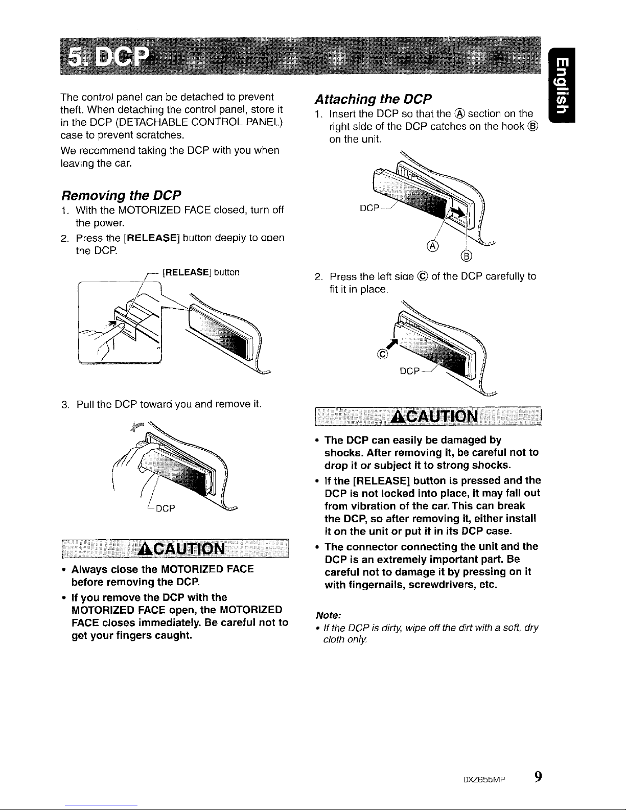
I
Note:
•Ifthe
DCP
is dirty, wipe
off
the dirt with a soft,
dry
cloth
only
2.
Press the left side ©
of
the
OCP
carefully to
fit it in place.
• The DCP can easily be damaged
by
shocks. After removing
it,
be careful not
to
drop it or subject it to strong shocks.
• If the [RELEASE] button
is
pressed and the
DCP
is
not locked into place,itmay fall out
from vibration of the car. This can break
the DCP, so after removing it, either install
it
on
the unit or put itinits DCP case.
• The connector connecting the unit and the
DCP
is
an extremely important part.
Be
carefUl not to damage it by pressingonit
with fingernails, screwdrivers, etc.
Attaching the
DCP
1.
Insert the DCP so that the ® section
on
the
right side of the
OCP
catches
on
the hook ®
on
the unit.
3.
Pull the DCP toward you and remove
it.
• Always close the MOTORIZED
FACE
before removing the
DCP.
• If you remove the DCP with the
MOTORIZED FACE open, the MOTORIZED
FACE
closes immediately. Be careful not to
get your fingers caught.
Removing the
DCP
1.
With the MOTORIZED
FACE
closed, turn off
the power.
2.
Press the [RELEASE] button deeplytoopen
the
DCP.
~
[RELEASE] button
~~
'r!
I
~
The control panel can be detached to prevent
theft. When detaching the control panel, store it
in
the DCP (DETACHABLE CONTROL PANEL)
case to prevent scratches.
We
recommend taking the DCP with you when
leaving the car.
DXZ655MP
9
Page 10
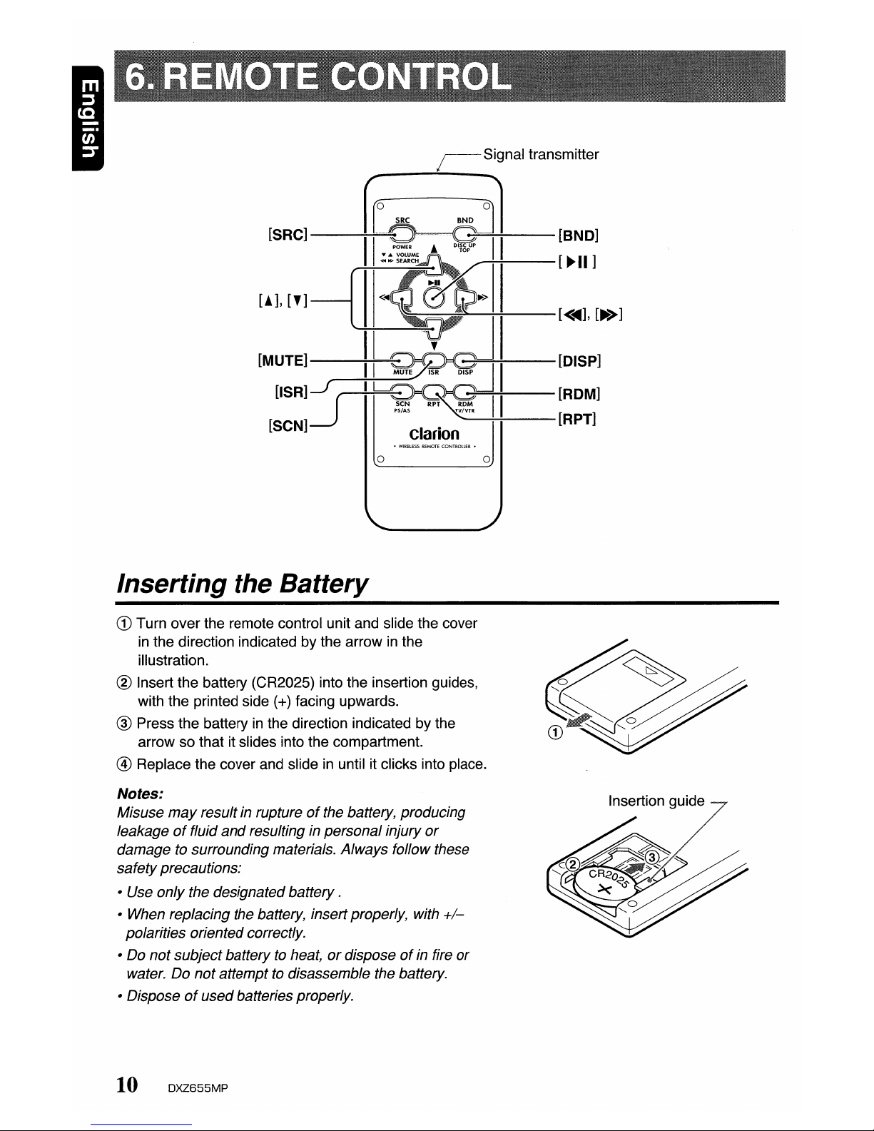
[SRC]--~
[!],
[']
[MUTE]--~=
USR1J(
[SCN]~
o
Inserting the Battery
~--[BND]
~=---[~II]
CD
Turn
over
the
remote control unit and slide
the
cover
in
the
direction indicatedbythe
arrowinthe
illustration.
® Insert
the
battery (CR2025) into
the
insertion guides,
with
the
printed side (+) facing upwards.
® Press
the
battery in
the
direction indicatedbythe
arrowsothat
it slides into
the
compartment.
@
Replace
the
cover
and slide in until it clicks into place.
Notes:
Misuse
may
result in ruptureofthe battery, producing
leakage
of
fluid
and
resulting in personal injury
or
damage to surrounding materials. Always follow these
safetyprecautions:
• Use only the designated
battery.
• When replacing the battery, insertproperly, with
+/-
polarities oriented correctly.
• Do
not
subjectbattery to heat,ordisposeofin fire or
water. Do
not
attempttodisassemble the battery.
• Dispose
of
usedbatteries properly.
10
DXZ655MP
Insertion
guide
Page 11
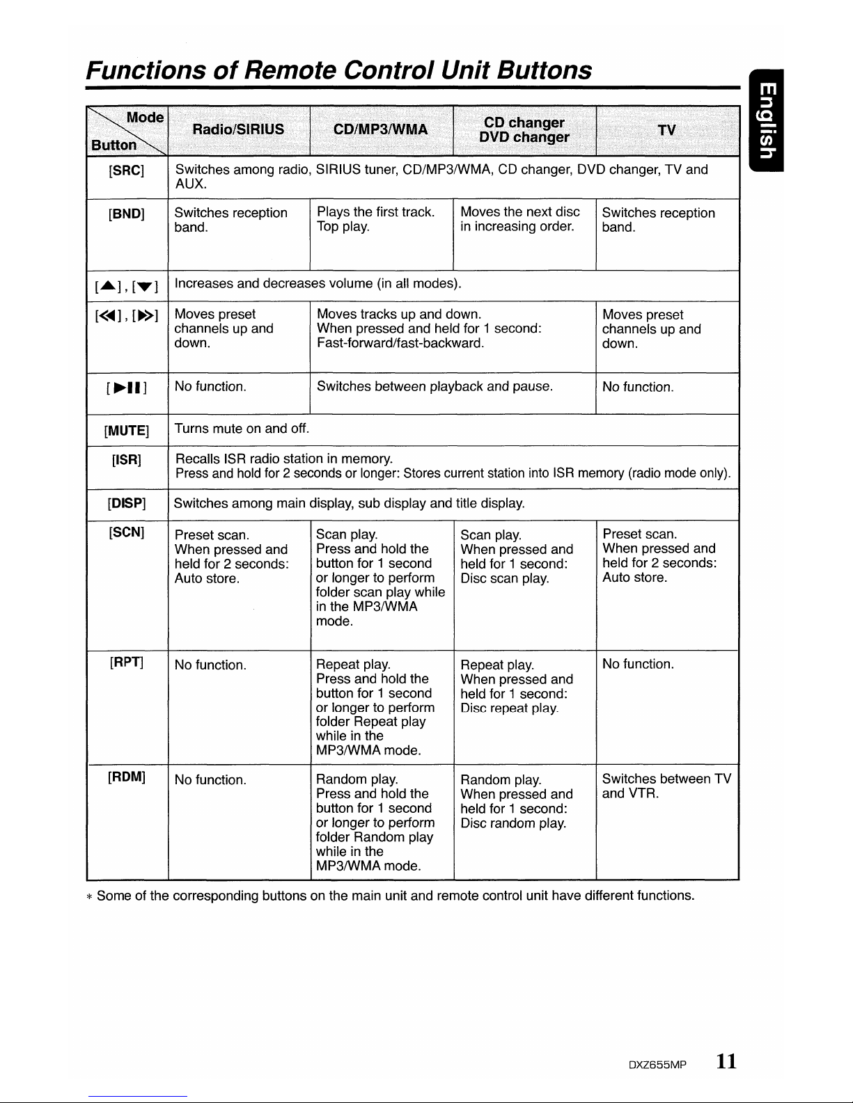
Functions
of
Remote Control Unit Buttons
"-
x/
.~~i
..........
nunrllill
i/
.~
...•........
[SRC]
Switches among radio, SIRIUS tuner, CD/MP3/WMA, CD changer, DVD changer, TV and
AUX.
[BNO]
Switches reception
Plays the first track. Moves the next disc
Switches reception
band.
Top play.
in
increasing order.
band.
[A],[T]
Increases and decreases volume (in all modes).
[<~],[~>]
Moves preset Moves tracks up and down.
Moves preset
channels up and When pressed and held for 1 second:
channels up and
down. Fast-forward/fast-backward.
down.
[~II]
No function.
Switches between playback and pause.
No function.
[MUTE]
Turns mute on and off.
[ISR]
Recalls ISR radio station in memory.
Press and hold for 2 seconds or longer: Stores current station into
ISR
memory (radio mode only).
[OISP]
Switches among main display, sub display and title display.
[SCN]
Preset scan.
Scan play.
Scan play.
Preset scan.
When pressed and
Press and hold the
When pressed and
When pressed and
held for 2 seconds:
button for 1 second
held for 1 second:
held for 2 seconds:
Auto store.
or
longer to perform
Disc scan play.
Auto store.
folder scan play while
in
the
MP3/wMA
mode.
[RPT]
No function.
Repeat play.
Repeat play.
No function.
Press and hold the
When pressed and
button for 1 second
held for 1 second:
or longer to perform
Disc repeat play.
folder Repeat play
while in the
MP3/wMA
mode.
[ROM]
No function.
Random play.
Random play.
Switches between TV
Press and hold the
When pressed and
and VTR.
button for 1 second
held for 1 second:
or longer to perform
Disc random play.
folder Random play
while in the
MP3/wMA
mode.
* Some of the corresponding buttons on the main unit and remote control unit have different functions.
DXZ655MP
11
Page 12

Note: Be suretoread this chapter referringtothe
front diagrams
of
chapter
"3.
CONTROLS"on page 5 (unfold).
Adjusting
the volume
1. Press the front
part
of the [ROTARY] knob.
The
knob will
pop
up.
2. Turning
the
[ROTARY] knob clockwise
increases
the
volume; turning it
counterclockwise decreases the volume.
*The
volume
level is from a (minimum) to
33
(maximum).
Be
suretolower
the
volume
before
switching
off
the
unit
powerorthe
ignition
key. The
unit
remembers
its
last
volume
setting.Ifyou
switch
the
power
off
with
the
volume
up,
when
you
switch
the
power
back
on,
the
sudden
loud
volume
may
hurt
your
hearing
and
damage the unit.
I
Basic
Operations
Selectingamode
1. Press
the
[SRC] button to change
the
operation mode.
2.
Each
time
you press the [SRC] button,
the
operation mode changesinthe
following
order:
Radio
mode~SIRIUS mode~CO/MP31
WMA
mode~CD changer
mode
....
DVD
changer
mode~TV
mode
...
AUX
mode
~
Radio
mode
...
* External equipment not connected with
CeNET
is
not displayed.
Turning
on/off
the
power
Note:
• Be careful about using this unit for a long time
without running the engine.
If
you drain the car's
battery too
far,
you may not be able to start the
engine
and
this can reduce the service lifeofthe
battery.
1. Press
the
[SRC] button.
2.
The
illumination and display on the unit light
up.
The
unit automatically remembers its last
operation
mode
and will automatically switch
to
display
that mode.
3. Press
and
hold the [SRC] button
for
1
second
or
longer to turn off the
power
for
the
unit.
Note:
• System check
The
first time this unit is turnedonafter the wire
connections are completed,
it
must be checked
what equipment is connected. When the
power
is
turned
on,
the "SYSTEM CHECK" appearsinthe
display, then the unit returns to the clock display
mode. The system check starts within the unit.
When the system check is complete, press the
[SRCj button again.
*
In
the case of a user title, only the top level
is
displayed.
*
In
the case of radiolTV/AUXlDVD changer, the
display cannot
be
switched to "title display."
*Once selected, the preferred display becomes
the display default. When a function adjustment
such
as
volumeismade,
the
screen will
momentarily switch
to
that function's display,
then revert back to the preferred display
several seconds after
the
adjustment.
* If the button operation
is
performed with the
screen saver function
on,
the operation
display corresponding
to
the
button operation
is
shown for about30seconds and the display
returns to the screen saver display.
For details, refer
to
the subsection "Turning
the
screen saver
functiononor
off'insection
"Operations Common
to
Each Mode."
•Title
display
I
[]
....
GAAAAFlRRFtRRA
r::JRARRARAAAAA
GARAAARRRAFIR
•••••••••
llllllullnllllllll~1
..
Level bar display
•
Sub
display
Switching
the
display
Press
the
[D] buttontoselect the desired
display.
Each time you press the
[D] button, the display
switches
in
the
following order:
• Main
display
D
t:-
DXZ655MP
12
Page 13

Basic
Operations
Adjusting
the
subwoofer
output
volume
You
can
adjust
the volume output from the unit's
subwoofer
output
terminal.
1. Press the [A-M] button and select
"SUB-WOOF VOL 0".
2. Turning the [ROTARY] knob clockwise
increases the output volume; turning it
counterclockwise decreases the output
volume.
*The factory default setting
is
"0". (Setting
range:
-6to6)
3.
When
the
adjustment is complete, press
the
[A~M]
button several times until the function
mode is reached.
Adjusting
the
tone
I
Press
the
[A~M]
button and select the item to
adjust. Each time you press the
[A~M]
button,
the item
changes
as following order:
• When
"Z+
BASS BOOST"isset
"SUB~WOOF
VOL
0"~"BASS
BOOST 0"
~
"BALANCE
0"
~
"FADER
0"
~
Last
function
mode.
• When
"Z+
IMPACT"isset
"SUB~WOOF
VOL
0"
~
"IMPACT
0"
~
"BALANCE
0"
~
"FADER
0"
~
Last
function
mode.
.When
"Z+
EXCITE"isset
"SUB~WOOF
VOL
0"
~
"EXCITE
0"
~
"BALANCE
0"
~
"FADER
0"
~
Last
function
mode.
• When
"Z+
CUSTOM"isset
"SUB~WOOF
VOL
0"
~
"~
BASS GAIN
0"
~
"~
TREBLE
GAIN
0"
~
"BALANCE
0"
-.
"FADER
0"
~
Last
function
mode.
• When
"Z+
OFF"isset
"SUB-WOOF VOL
0"
~
"BALANCE
0"
~
"FADER
0"
~
"Last
function
mode.
*
"SUB~WOOF
VOL" can be adjusted only when
"SUB-WOOFER"
is
set to "ON",
bass emphasized
bass and treble
emphasized
bass and treble
emphasized mid deemphasized
user custom
no sound effect
Adjusting
the
Z-Enhancer
Plus
1. Press the [Z+] button and select
the
Z-
Enhancer
Plus mode to adjust.
2. Press the [A-M] button and turning the
[ROTARY] knob clockwise adjusts
in
the
+
direction; turning it counterclockwise adjusts
in
the - direction.
.When
"BASS BOOST 0" selected, you can
adjust
the
bassinthe range of-3to 3.
.When
"IMPACT 0" selected, you can
adjust
the
bass and treble in
the
range
of
-3
to 3.
.When
"EXCITE 0" selected, you can adjust
the bass and treble
in
the range of-3to 3.
* When Z-Enhancer Plus is selected, press and
hold the [Z+] button for
1 second or longer
to
change to the "CUSTOM" mode.
Bass/treble characteristics become flat and the
"Z+
FLAT' is shown
in
the display.
Press the [Z+] button again to change to the
"Z+
OFF"
mode.
• Z+ EXCITE
Setting
the
Z-Enhancer
Plus
This unit are provided with 4 types of sound
tone effects stored
in
memory. Select the one
you prefer.
*The factory default setting
is
"Z+ OFF".
Each time
you
press the [Z+] button, the tone
effect
changes
in the following order:
"Z+
OFF"-."Z+
BASS BOOST"~"Z+
IMPACT"~"Z+
EXCITE"~"Z+
CUSTOM"
~
"Z+
OFF"
...
• Z+
BASS
BOOST:
•Z+IMPACT
• Z+
CUSTOM
• Z+ OFF
DXZ655MP
13
Page 14

Basic
Operations
I
Adjusting
the
bass
The bass gain, bass FREQ (center frequency)
and bass Q can be adjusted as follows.
1.
Press the [A-M] button and select"~BASS
GAIN 0".
2.
Press the
[<
....,..
>]
lever upward or
downward and select from
"~
BASS GAIN 0" ..."~BASS FREQ 50"
...
"~
BASS Q
1"",
"~.BASS
GAIN 0"...
3.
Turn the [ROTARY] knob to adjust the gain,
the FREQ (center frequency) and the
Q.
BASS
GAIN:
-6
to 8 (The factory default
setting is "0")
BASS
FREQ:
50Hz/80Hz/120Hz (The
factory default setting
is
"50")
BASS Q : 1/1.25/1.5/2 (The factory
default setting
is"1")
4.
When the adjustment is complete, press the
[A-M] burton several times until the function
mode
is
reached.
Adjusting
the treble
The treble gain and treble FREQ (center
frequency) can be adjusted as follows.
1.
Press the [A-M] button and select
".
TREBLE GAIN 0".
2.
Press the
[<
....,..
>]
lever upward or
downward and select from
".
TREBLE
GAIN0"..."~TREBLE FREQ
12K"
..."~TREBLE GAIN0"...
3.
Turn the [ROTARY] knob to adjust the gain
and the FREQ (center frequency).
TREBLE
GAIN:
-6
to 6 (The factory default
setting
is
"0")
TREBLE FREQ : 8KHz/12KHz (The factory
default setting
is
"12K")
4.
When the adjustmentiscomplete, press the
[A-M] button several times until the function
mode is reached.
14 OXZ655MP
Adjusting
the balance
1.
Press the [A-M] button and select
"BALANCE
0".
2.
Turning the [ROTARY] knob clockwise
emphasizes the sound from the right
speaker; turning it counterclockwise
emphasizes the sound from the left speaker.
*
The
factory default settingis"0".
(Adjustment
range:
L13toR13)
3.
When the adjustment is complete, press the
[A-M] button several times until the function
mode is reached.
Adjusting
the fader
1.
Press the [A-M] button and select "FADER
0".
2.
Turning the [ROTARY] knob clockwise
emphasizes the sound from the front
speakers; turning it counterclockwise
emphasizes the sound from the rear
speakers.
*
The
factory default settingis"0".
(Adjustment
range:
F12toR12)
3.
When the adjustmentiscomplete, press the
[A-M] button several times until the function
mode
is
reached.
Adjusting
MAGNA BASSEXTEND
The MAGNA BASS EXTEND does not adjust
the low sound area like the normal sound
adjustment function, but emphasizes the deep
bass sound area to provide you with a dynamic
sound.
*
The
factory default settingisoff.
1.
Press and hold the [A-M] button for 1
second or longer to turn on the MAGNA
BASS EXTEND effect. "M-BASS EX ON"
lights
in
the display.
2.
Press and hold the [A-M] button for 1 second
or longer to turn offthe MAGNA BASS
EXTEND effect. "M-BASS EX OFF" lights
in
the display.
Page 15

Radio Operations
Listening to the radio
1.
Press the [SRC] button and select the radio
mode. The frequency appears
in
the display.
2.
Press the [BND] button and select the radio
band. Each time the button
is
pressed, the
radio reception band changes
in
the
following order:
FM1-+FM2-+FM3-+AMi-+FM1
...
3.
Press the
[<
...,
..->]
lever upward or
downward to tune
in
the desired station.
Tuning
There are 3 types of tuning mode available, seek
tuning, manual tuning and preset tuning.
Seek
tuning
1.
Press the [BND] button and select the
desired band (FM or AM).
* If "MANU"
is
litinthe
display,
press
and
hold
the [BND] button for 1
secondorlonger.
"MANU"inthe
display
goes
off
and
seek
tuning is now available.
2.
Press the
[<
... ,
..->]
lever upward or
downward to start automatic station tuning.
When the lever
is
pressed upward, search
will be performing
in
the direction of higher
frequencies. When the lever
is
pressed
downward, search will
be
performedinthe
direction of lower frequencies.
Manual tuning
There are 2 ways available: Quick tuning and
step tuning.
When you are in the step tuning mode, the
frequency changes one step at a time.
In
the
quick tuning mode, you can quickly tune the
desired frequency.
1.
Press the [BND] button and select the
desired band (FM or AM).
*
If
"MANU"isnot litinthe
display,
press
and
hold the [BND] button for 1 second or
longer.
"MANU"islitinthe display
and
manual tuning
is
now available.
2.
Tune into a station.
•
Quick
tuning:
Press the «
...
,
..->]
lever upward or
downward and hold
in
position for 1 second
or longer to begin station tuning.
.Step
tuning:
Press the
[<
...,
..->]
lever upward or
downward to perform manual tuning.
Recalling a preset station I
A total of 24 preset positions (6-FM1,6-FM2,
6FM3, 6-AM) exists to store individual radio
stations
in
memory. Pressing the corresponding
[DIRECT) button recalls the stored radio
frequency automatically.
1.
Press the [BND] button and select the
desired band (FM or AM).
2.
Press the corresponding [DIRECT] button to
recall the stored station.
*Press
and
hold
one
of the [DIRECT] buttons
for 2 seconds or longer
to
store that station
into preset memory.
Manual memory
1.
Select the desired station with seek tuning,
manual tuning or preset tuning.
2.
Press and hold one of the [DIRECT] buttons
for 2 seconds or longer to store the current
station into preset memory.
Auto store
Auto store is a function for storing up to 6
stations that are automatically tuned
in
sequentially. If 6 receivable stations cannot be
received, a preViously stored station remains
unoverwritten at the memory position.
1.
Press the [BND] button and select the
desired band (FM or AM).
2.
Press and hold the
[I»II
]button for 2
seconds or longer. The stations with good
reception are stored automatically to the
preset channels.
*
If
auto storeisperformedintheFMbands, the
stations
are
storedinFM3
evenifFM1orFM2
was
chosen for storing stations.
Preset scan
Preset scan receives the stations stored
in
preset memory in order. This function is useful
when searching for a desired station
in
memory.
1.
Press the
(1»11]
button.
2.
When a desired station is tuned in, press the
[I»II
]button again to continue receiving that
station.
Note:
• Be careful
nottopress
and
hold
the
[I»II
]button
for
2 seconds or longer, otherwise the auto store
function is engaged
and
the unit starts storing
stations.
OXZ655MP
15
Page 16

Radio Operations
I
Instant
station
recall (ISR)
Instant station recallisa special radio preset
that instantly accesses a favorite radio station at
a touch of a button.The ISR function even
operates with the unit
in
other modes.
.ISR
memory
1.
Select the station that you wishtostoreinISR
memory.
2.
Press and hold the [ISR] button for 2 seconds
or longer.
•
Recallingastation
with
ISR
In
any mode, press the [ISR] button to turn on
the radio function and tune the selected radio
station. "ISR" appears
in
the display. Press the
[ISR] button again to return to the previous
mode.
CDIMP31WMA Operations
MP31WMA
WhatisMP3?
MP3 isanaudio compression method and
classified into audio layer 3 of MPEG standards.
This audio compression method has penetrated
into PC users and become a standard format.
This MP3 features the original audio data
compression to about 10 percent of its initial
size with a high sound quality. This means that
about 10 music CDs can be recorded
on
a CD-
R disc or CD-RW disc to allow a long listening
time without having to change CDs.
WhatisWMA?
WMAisthe abbreviation of Windows Media
Audio, an audio file format developed
by
Microsoft Corporation.
Notes:
• If you
playa
file with DRM (Digital Rights
Management) for
WMA
remaining
ON,
no audio
is
output (The
WMA
indicator blinks).
• Windows Media
TM,
and
the Windows ® logo are
trademarks,
or
registered trademarksofMicrosoft
Corporation in the United States and/orother
countries.
•Todisable
DRM
(Digital Rights Management):
1. When using Windows Media Player
8,
click
on TOOLS
~
OPTIONS~COpy
MUSIC
tab, then under
COpy
SETIINGS,
unclick
the check box for PROTECT CONTENT.
Then, reconstruct files.
2.
When using Windows Media Player9,click
on TOOL
~
OPTIONS~MUSIC RECORD
tab, then under Recording settings, unclick
the Check box for RECORD PROTECTED
MUSIC. Then, reconstruct files.
Personally constructed
WMA
files are used
at your own responsibility.
Precautions
when
creating
MP31WMA
disc
•
Usable
sampling
rates
and
bit
rates:
1. MP3: Sampling rate 11.025 kHz-48 kHz,
Bit rate: 8 kbps-320 kbps / VBR
2.
WMA
Bit rate 48 kbps-192 kbps
• File
extensions
1.
Always add a file extension ".MP3" or
".WMA" to MP3 or WMA tile by using single
byte letters. If you add a file extension other
than specified or forget to add the file
extension, the file cannot be played.
16
DXZ655MP
Page 17

I
CDIMP31WMA Operations
2.
Files without MP3IWMA data will not play.
The indication
"--:--"
appears in the play
time display if you attempt to play files
without
MP3IWMA
data.
• Logical
format
(File system)
1.
When writing MP3IWMA file on a CD-R disc
or CD-RW disc, please select "1809660 level
1,2orJOLIETorRomeo" as the writing
software format. Normal play may not be
possible if the disc
is
recorded on another
format.
2.
The folder name and file name can be
displayed as the title during MP3IWMA play
but the title must be within 128 single byte
alphabetical letters and numerals (including
an extension).
3.
Do not affix a name to a file inside a folder
having the same name.
• Folder
structure
1.
A disc with a folder having more than 8
hierarchical levels will be impossible.
• Numberoffilesorfolders
1.
Up to 255 files can be recognized per folder.
Up to 500 files can be played.
2.
Tracks are played in the order that they were
recorded onto a disc. (Tracks might not
always be played in the order displayed on
the PC.)
3.
Some noise may occur depending on the type
of encoder software used while recording.
Multisession
function
When a disc contains both normal
CD
type tracks
and MP3JWMA type tracks mixedly, you can
select which type of the recorded tracks to
play.
• Default valueis"CD".
Each time you press and hold the [BND] button
for 1 second
or
longer, the mixed mode is
switched between CD type or MP3IWMA type.
The following indication appears in the title
display when switching the track type to be
played.
• Display when
CD
type
iM..SESS
CDI
trackisselected:
• Display
when
MP3IWMA
I----
t
-.---.--
type
trackisselected:
IM~SESS
MP31
1.
Types of recording that can be played are as
follows.
D~
SettoCD
Set
to
MP3IWMA
ISC
Mixed
with
CD
and
Play CD
Play
MP3/wMA
MP3IWMA
type
tracks
CD type track only
Play
CD
Play CD
MP3JWMA
type
track
only
Play
MP3/wMA
Play
MP3/wMA
2.
After making these settings, remove the disc
and then reinsert it.
3.
When a mixed mode CD is loaded and CD is
set, the track to be played first is MP3JWMA
file data and no sound is heard.
Note:
• When playing a GCCD (Copy Control CD), set the
setting to CD type. When this is set to MP3IWWA
type, the CD cannot be playednormally
in
some
cases.
Disc../n-P/ay
function
As long as the ignition key is turned to the ON or
ACC position, this function allows you to turn the
power to the unit and start playing the disc automatically when the disc is inserted
even if the
power is not turned on.
• Do
not
trytoput
your
handorfingers in
the
disc
insertion
slot.
Also
never
insert
foreign
objects
into
the slot.
• Do
not
insert
discs
where adhesive comes
out
from
cellophane tapeora rental
CO
label,ordiscs
with
marks where
cellophane tape
or
rental CD labelswere
removed. It
maybeimpossibletoextract
these
discs
from
the
unit
and they may
cause
the
unittobreak
down.
Backup
Eject
function
Just pressing the
[~]
button ejects the disc
even if the power to the unit was not turned on.
1.
Press the
[~]
button. The MOTORIZED
FACE opens and a CD ejects.
"EJECT"
appears in the display.
Be careful
nottoget
your
fingers
caught
when
opening
and
closing
the
MOTORIZED
FACE.
2.
Remove the CD and press the
[~]
button to
close the MOTORIZED FACE.
OXZ655MP
17
Page 18

CDIMP31WMA
Operations
I
Notes:
•Besure
to close the
MOTORIZED
FACE
after
removing
the CD.
•
The
MOTORIZED FACE closes automatically 30
seconds
after
removing the CD.
•
If
a
CD
(12 em) is left
in
the
ejectedposition for
15
seconds, the CD is automatically reloaded. (Auto
reload)
• 8 cm CDs are not auto reloaded. Be sure
to
remove
it when ejected.
•
If
you force a CD into before auto reloading, this can
damage the
CD.
Listening
to a
disc
already
loaded
in
the
unit
Press the [SRC] button to select the CO/MP31
WMAmode.
When the unit enters the CD/MP3IWMA mode,
play starts automatically.
If there
is
no disc loaded, the indication "NO
DISC"appears
in
the title display.
*'
The
mode changes
each
time
the
[SRC] button
is
pressed. (Modes
are
not
displayed for equipment
that
is
not connected.)
Radio~(SIRIUS)
~
CD/MP3IWMA~(CD
changer)
~
(DVD changer)~(TV)
~
AUX
~
Radio
...
Loading
a CD
1.
Press the
[~]
button. The MOTORIZED
FACE
opens.
Be
careful
nottoget
your
fingers
caught
when
opening
and
closing
the
MOTORIZED
FACE.
2.
Insert a CD into the center of the CD SLOT
with the labeled side facing
up.
The CD plays
automatically after loading.
Notes:
•
Never
insert
foreign objects into the
CD
SLOT
•Ifthe CD is not inserted
easily,
there may be another
CD
in
the
mechanism or
the
unit may require service.
• Discs
not
bearing
the
~Q~~
or
~&J
mark
and
CO-ROMs
cannotbeplayedbythis
unit
•
Some
CDs
recordedinCD-R/CD-RW
mode
may
notbeusable.
18
DXZ655MP
Loading8cm
compact
discs
*
No
adapter is requiredtoplayan8
cm
CD.
*'
fnsert
the8cmCDinto
the
centerofthe
CD
SLOT
3.
After loading a
CD,
the MOTORIZED FACE
closes automatically.
Notes:
•
Note
that
MOTORIZED
FACE closes
immediately
afteraCOisinserted
into CO SLOT.
•
IfnoCOisloaded
in the MOTORIZED FACE,
it
closes
after30seconds.
Pausing
play
1.
Press the
[~II]
button to pause
play.
"PAUSE" appears
in
the display.
2.
To
resume CD
play,
press the
[~II]
button
again.
Displaying
CD
titles
This unit can display title data for CD-textlMP3/
WMA disc and user titles input with this unit.
1.
Press the
[D]
button to display the title.
2.
Each time you press the
{T]
button, the title
display changes
in
the following order:
Notes:
•IftheCOplayingisnot
a CO-text CO
ornouser
title
has
been
input,
"m
NO
TITLE"
appears
in
the display.
• If
MP3IWMA
discisnot
input
TAG,
"6
NO
TITLE"
appears
in the display
•
For
MP3,
supports
103 Tags V2,3
/2.2/
1.1
/ 1.0.
•
Tag
displays give
priority
to V2.3
/2.2-
• In the
caseofalbum Tags for WMA, the
information written into the extension
header
is
displayed.
•
Only
ASCII
characters
can
be displayed in Tags.
Page 19

I
CDIMP31WMA Operations
Selecting
a
track
• Track-up
1. Press the
[<
....,..
>]
lever upward to move
to
the beginning of the next track.
2. Each time the
[<
....,..
>]
lever is pressed
upward, playback proceeds to another track
in the advancing direction.
• Track-down
1.
Press the
[<
....,..
>]
lever downward to move
the beginning of the current track.
2.
Press the
[<
....,..
>]
lever downward twice to
move to the beginning of the previous track.
Fas~forwardnas~backward
• Fast-forward
Press the
[<
....,..
>]
lever
upward
and
hold in
position for 1 second or longer.
• Fast-backward
Press the
[<
....,..
>]
lever downward and hold in
position for 1 second
or
longer.
=!:
For MP3IWMA discs, it takes some time until the
start
of
searching and between tracks.Inaddition,
the playing time may
have
a margin of error.
Folder
Select
This function allows you to select a folder
containing
MP3IWMA
files and start playing
from the first track
in
the folder.
1. Press the [ON] or the [UP] button.
Press the [ON] button to move the previous
folder. Press the [UP] button to move the
next folder.
1
~.~
Root folder
J'
J'
* Press the [UP] button while
in
the final folder
to shift to the first
folder.
* Folder without
an
MP3IWMA fileisnot
selectable.
2.
To
select a track, press the
[<
....,..
>]
lever
upward or downward .
Top
function
The top function resets the CD playerto the first
track of the disc. Press the [BND] button to play
the first track (track
No.1)
on the disc.
*
In
caseofMP3IWMA, the first trackofafolder being
played will
be
returned.
Other various
play
functions
• Scan
play
This function allows you to locate and play the first
10 seconds of all the tracks recorded
on
a disc.
1.
Press the [SeN] button to perform scan play.
"J' SeN" appears in the display.
*Scan play starts from the next track after the
track currently being played.
• Folder scan play
This function allows you to locate and play the
first 10 seconds of the first track of all the
folders on an
MP3IWMA
disc.
1.
Press and hold the [SeN] button for 1
second or longer to perform folder scan play.
"\HI
SeN" appears
in
the display.
* Folder scan play starts
from
the next track
after the track currently being played.
• Repeat
play
This function allows you to play the current track
repeatedly.
1.
Press the [RPT] button to perform repeat
play.
"I'
RPT"
appears in the display.
• Folder repeat
play
This function allows you to
playa
track currently
being played in the MP3IWMA folder repeatedly.
1.
Press and hold the [RPT] button for 1 second
or longer to perform folder repeat play.
"II RPT" appears in the display.
• Random play
This function allows you to play all tracks
recorded on a disc in a random order.
1.
Press the [ROM] buttontoperform random
play.
"J' ROM" appears
in
the display.
• Folder random play
This function allows you to play all the tracks of
all the folders recorded
on
an MP3IWMA disc in
a random order.
OXZ655MP 19
Page 20

20
DXZ655MP
CDIMP31WMA Operations
I
1.
Press
and
hold
the
[ROM] button for 1
secondorlongertoperform
folder
random
play.
"lEI
RDM"
appears
in the display.
• To cancel play
1.
Press
the
operating button
previously
selected.
Play
list
mode
This
function allows you to
play
tracks, up
to
latest 5
time
stamps,byreading the
play
list
information written on the disc.
1.
Press
and
hold
the
[P.LlST] button for 1
secondorlonger
to turn onoroff
the
play list
mode.
* Play list play is possible only when there
is
a
file whose extension
is
".M3U"
on
the CD-RI
RW.
* Up to 5 play lists can
be
recognized, and up to
255 files can
be
recognized per play list.
2. Press
the
[<..-,
~>]
lever
upward
or
downwardtochange
the track.
3.
Press
the
[DN] button to
move
to the
previous
play
list.
Press
the
[UP] button to
movetothe
next
play
list.
Notes:
• The SCNIRPTIRDM functions cannot be used
while in the
play
list mode.
• The title display changes from folder name to
play
list name.
Makingaplay
list
1.
Write
desired
trackstoa CD-R/RW, etc.
Be
sure to
use
alphanumeric/ASCII characters
for
all file names.
2.
Makeaplay
listbyusing a
multimedia
player, etc. and save the data.
The
file
format
mustbeM3U.
3.
Again, write this play list to the CD-R/RW,
etc.
Notes:
• When wrWng
to
a CD-RIRW, etc., be sure to use
alphanumeric!ASCII characters.
• Up to
5 layers can be recognized as a list. For
written
play
lists, latest5 lists are recognized in
the order in which they are written.
• When writing
to
a CD-RIRW, etc.,
tum
off
the Disc
At
Once function.
• When adding
a play
fist,
it is recommended to
write it in the Root folder.
Operations Common to
Each Mode
To
change
display
setting
1.
Press
and
hold
the
{D] button for 1
second
or
longer
to switch to the
adjustment
selection
display.
2. Press
the
[<..-,
~>]
lever
upward
or
downward
to select the "item name".
"CLOCK"
+-+
"SPE/ANA
PTN"
+-+
"S/A
SENS"
+-+
"S/A
SPEED"
+-+
"SCREEN
SVR"
+-+
"MSG
INPUT"
+-+
"AUTO
SCROLL"
+-+
"SCRL
SPEED"
+-+
"DIMMER
LV"
+-+
"CONTRAST"
3. Turn the {ROTARY]
knob
to select the
"desired setting value".
*
In
the case of item names appearing with the
"Push ENT'
SUffix,
after the item name, the
["II
Jbutton must
be
pressed to display the
sefflng value.
*After completing settings, press the
[OJ
button
to return to the previous mode.
• Setting the
clock
2-1.
Select"~
CLOCK
..
'W-i1..#""U
....
".
3-1.
Press
the ['-11] button.
3-2. Press the
[<..-,
~>]
lever
upward
or
downward
to select
the
hourorthe
minute.
3-3. Turn the [ROTARY]
knob
to set
the
correct
time.
*The clock
is
displayedin12-hour format.
3-4.
Press
the
['-11] button to store the
time
into
memory.
Note:
•
You
cannot set
the
clock when it is displayed with
only
the
ignition
on.
Ifyou drain
or
remove
the
car's
battery
or
take out this unit, the clock is reset. While
setting the clock,
if
anotherbuttonoroperation
is
selected, the clocksetmode is canceled.
• Setting the spectrum analyzer pattern
*The factory default setting
is
"1"
2-1.
Select"~
SPE/ANA
PTN".
• When the Main displayorTitle display is set
3-1. Turn the [ROTARY] knob to select the
setting.
Each
time
you turn the {ROTARY] knob,
the
setting
changes
in the following order:
"~
SPE/ANA
PTN
1""'''~
SPE/ANA
PTN
2"
...
"~
SPEI
ANA
PTN
3"
...
"~
SPEI
ANA
PTN
4"
...
"~
SPEI
ANA
PTN
SRC
ICON"
• When
the
Sub
displayisset
3-2. Turn the [ROTARY] knobtoselect
the
setting.
Page 21

•
Entering
MESSAGE INFORMATION
Message up to 30 characters long canbestored
in
memory and displayed as a type of screen
saver
setting.
*The factory default setting
is
"Welcome
to
Clarion".
2-1.
Select"~
MSG INPUT 'bil@h.".
3-1. Press the
[---II]
button.
3-2. Press and hold the [BND] button for 1
second or longer to clear the old message.
3-3. Press the
[<
....
,
..,.>]
lever upward or
downward to move the cursor.
3-4. Press the [BND] button to select a
character. Each time you press the [BND]
button, the character changes
in
the
following orders:
Capital letters
....
Small letters ... Numbersl
Symbols'"
Umlaut
...
Capital letters...
3-5. Turn the [ROTARY] knob to select the
desired character.
3-6. Repeat step 3-3 to 3-5toenter up to 30
characters for message.
3-7. Press and hold the
[~II]
button for 2
seconds or longer to store the message
in
memory and cancel input message mode.
* Press
and
hold
the
[BND] button for 1second
or
longertocancel
the
input message.
Then
press
and
hold
the
["'11
]button for 2 seconds
or
longertostore the message
and
the
message
returntodefault setting.
• Setting the
method
for
title
scroll
Set how to scrollinCD-TEXT, MP3IWMAtitle.
*
The
factory default setting
is
"ON",
2-1. Select"~AUTO SCROLL".
3-1. Turn the [ROTARY] knob to select "ON" or
"OFF".
-ON:
To
scroll automatically.
-OFF:
To
scroll just 1time when the title was
changed or the [T] button was pressed for
1 second or longer.
•
Adjusting
the
display
scroll
speed
This feature allows you to slow down the scroll
speed when the scroll speed
is
too fast, making
it difficult to view the screen.
*
The
factory default settingis"SPEED
3"
2-1.
Select"~
SeRl
SPEED".
3-1. Turn the [ROTARY] knob to select the
setting.
Operations
Common
to
Each Mode
Each time you turn the [ROTARY] knob,
the setting changes
in
the
follOWing
order:
"~
SPE/ANA
PTN
1"'"
"¢
SPE/ANA PTN
2"
...
"¢
SPE/ANA
PTN
3"
...
"¢
SPEI
ANA
PTN 4"
•
Setting
the
sensitivityofthe
spectrum
analyzer
This function allows youtoadjust the sensitivity
of the spectrum analyzer.
* The factory default setting
is
"MID"
2-1. Select"¢S/A
SENS".
3-1. Turn the [ROTARY] knob to select the
setting.
Each time you turn the [ROTARY] knob,
the setting changesinthe following order:
"~
S/A
SENS HIGH" ..."¢S/A
SENS
MID"
..."~S/A
SENS
lOW"
• Setting
the
speedofthe
spectrum
analyzer
This function allows youtoadjust the speed of
the spectrum analyzer.
'"
The
factory default settingis"HIGH"
2-1.
Select"~
SIA SPEED",
3-1. Turn the [ROTARY] knob
to
select the
setting.
Each time you turn the [ROTARY] knob,
the setting changes
in
the following order:
"~
S/A
SPEED HIGH" ..."~S/A SPEED
MID"
..."~S/A
SPEED
LOW"
• Turning
the
screen saver
function
on
or
off
This unit is provided with the screen saver
function which allows you to show various kinds
of patterns and characters
in
the operation
status indication area of the display
in
a random
order.
You
can turnonor off this function.
If
the button operation is performed with the
screen saver function
on,
the operation display
corresponding to the button operation
is
shown
for about 30 seconds and the display returns to
the screen saver display.
*The factory default setting
is
"RANDOM".
2-1.
Select"~
SCREEN SVR 'bil@h'''.
3-1. Press the
["'11]
button.
3-2. Turn the [ROTARY] knob to selectthe setting.
Each time you turn the [ROTARY] knob, the
setting changes
in
the following order:
"~
Pattern
OFF"
"¢
Pattern
SS1"
....
"~
Pattern
SS2"
"~
Pattern
SS3"
...
"~
Pattern
MESSAGE"
..."~Pattern
RANDOM"
DXZ655MP
II
21
Page 22

Operations
Common
to
Each
Mode
I
*This setting item can
be
adjusted within the
range SPEED 1
to
SPEED
6.
Adjust this setting item while viewing how the
appearance of the display changes.
• Dimmer level
You
can
adjust
the reduced illumination level of
the
dimmer.
*The factory default setting
is
"LV3".
(Adjustment range
is
LV1toLV5)
2-1.
Select"~
DIMMER
LV".
3-1. Turn
the
[ROTARY] knob to adjust
the
reduced illumination level of the dimmer.
•
LV1
to LV5:
The
dimmer
operation is performed
depending
on the set level
LV1toLV5.
•
OFF:
No
dimmer
operation is performed.
•
Adjusting
the display
contrast
You
can adjust the display contrasttomatch the
angle of installation of the unit.
* The factory default setting
is
"08". (Adjustment level:
01to16)
2-1.
Select"~
CONTRAST".
3-1. Turn
the
[ROTARY] knobtoadjust
the
contrast.
To
change
other
settings
1.
Press
the
[ADJ]
button to switch to
the
adjustment selection display.
2. Press
the
[<
....,....
>]
lever upward
or
downward
to select the "item name".
Each time
the
[<..-,
....
>]
lever is pressed
up/
down,
the
item display changes in
the
following order:
"BLINK
LED"~"SUB-W"~"SUB-W
LPF"~"AMP
CANCEL"
~
"AUX
SENS"
~
"SYSTEM
CHECK"
3.
Turn
the
[ROTARY] knob to select the
"desired
setting
item".
*After completing settings, press the [ADJ]
button to return
to
the previous mode.
•
Anti-theft
indicator
The
red Anti-theft indicator is a function for
preventing theft.
When
the DCP is removed
from the unit, this indicator blinks.
*The factory default setting is "OFF".
2-1.
Select"~
BLINK
LED".
22 DXZ655MP
3-1. Turn
the
[ROTARY] knob to select "ON"
or
"OFF".
• Setting
the
Subwoofer
You
can set the subwoofer onoroff.
*The factory default setting
is
"ON".
2-1. Select
"~
SUB-W".
3-1. Turn the [ROTARY] knob to select "ON"
or
"OFF".
• Setting LOW PASS FILTER
*The factory default setting is "THROUGH".
*If subwoofer function is set "ON", "LOW PASS
FILTER" can be selected.
2-1.
Select"~
SUB-W
LPF".
3-1. Turn the [ROTARY] knob to select
the
setting. Each
time
you turn the [ROTARY]
knob,
the
setting changesinthe following
order:
THROUGH
-+50-+80-+
120
• Setting the external amplifier
*The factory default setting
is
"OFF".
2-1. Select
"~
AMP
CANCEL".
3-1. Turn
the
[ROTARY] knob to select "ON"
or
"OFF".
-ON:
Use with connected AMP.
-OFF:
Use with inside AMP.
• Selecting AUXINsensitivity
Make the following settings to select the
sensitivity
when
sounds
from external devices
connected to this unit are difficult to hear even
after
adjusting the volume.
*The factory default setting is "MID".
2-1.
Select"~
AUX
SENS".
3-1. Turn the [ROTARY] knob to select "LOW",
"MID"
or
"HIGH".
• Performing a
system
check
This function allows you to perform a system
check
from the adjust
mode
when required.
2-1.
Select"~
SYSTEM
CHECK
'*,,*'*"".
3-1. Press and hold the
["'11
]button for 1
secondorlonger.
"SYSTEM
CHECK"
appearsinthe display,
then
the
unit returns to the previous
operation mode.
Page 23

I
Operations
Common
to Each Mode
Entering
titles
Titles up to 10 characters long can be stored
in
memory
and displayed for
CD,
CO changer,
Radio stations and
TV
stations.
The
number of
titles that can
be
entered for each mode are as
follows.
Mode
Numberoftitles
CD mode
50
titles
TV
mode
20
titles
Radio mode
30 titles
CD
changer
mode
Numberoftitles
DCZ625 connected
100
titles
CDC655Tz
connected
100
titles
1. Press the [SRC] button to select the mode
you want to enter a title (Radio, CD, CD
changer
or
TV).
2. Select and
playa
CDinthe CD changer or
tune in to a
TV
station or Radio for which you
want to enter the title.
3.
Press the
[0]
button and display the title
display.
4.
Press and hold the [T] button for 1 second or
longer.
The display switches to the title input display.
5.
Press the
[<..-,
..
>]
lever
upward or downward
to move the cursor.
6.
Press the [BND] button to select a character.
Each time you press the [BND] button, the
character changes
in
the following order:
Capital letters
-+
Small letters-+Numbers!
Symbols
-+
Umlaut-+Capital letters...
7. Turn the [ROTARY] knob to selectthe
desired character.
8.
Repeat steps 5 to 7 to enter up to 10
characters for the title.
9.
Press and hold the
["'11
]button for 2
seconds
or
longer to store the title into
memory
and
cancel title input mode.
Clearing
titles
1.
Select and
playa
CDinthe CD changer
or
tune in to aTVstation or
TUNER
for which
you
want
to clear the title.
2.
Press the
[0]
button and display the title
display.
3.
Press
and
hold the [T] button for 1 second or
longer.
The display switches to the title input display.
4.
Press and hold the [BND] button for 1
second or longer.
A/I
characters in the title disappear.
5.
Press and hold the
["'11
]button for 2
seconds or longer to clear the title and
cancel title input mode.
Triggered
audio
mute
for
cellular
telephones
This unit requires special wiring to mute the
audio signal automatically when a cellular
telephone rings in the car.
*
This
functionisnot
compatible
with
all
cellulartelephones
Contact your local authorized Clarion dealer for
informationonproper
installation
and
compatibility.
AUX
function
This system has an external input jack so you
can listen to sounds and music from external
devices connected to this unit.
Setting
the
button
illumination
Press the [C] button to select a color type. Each
time you press the [C] button, the type changes
in
the following orders:
COLOR
SCAN-+Indigo
Blue-+Surf
Blue
-+
Silky
White-+Aqua
Green-+Fresh
Green
-+
Leaf
Green-+Warm
Amber-+Passion
Red
-+
Vivid
Pink-+Pale
Pink-+Dark
Violet
-+
Pure
Purple-+USER
COLOR
1-+USER
COLOR
2-+USER
COLOR
3-+COLOR
SCAN
...
.Setting
COLOR
SCAN
mode
As selecting
"COLOR
SCAN", the color
automatically changes.
* The factory default setting
is
"COLOR SCAN".
*After 3 seconds the color changes
to
the other.
.Setting
USER
mode
The
factory default settingis"RED
8",
"GREEN
8",
"BLUE
8".
As selecting "USER
COLOR
1, 2,
3",
press and
hold the [C] button for 1 second or longer to
enter the setting.
1.
Press the
[<
...
, ...>] lever upward or downward to
select
"*
RED 8"
-+
"*
GREEN 8"
-+
"*
BLUE
8".
2. Turn the [ROTARY] knob to select from 0 to
8.
3. Press and hold the
["'11
]button for 2
seconds or longer
to
store the color
in
memory and cancel setting mode.
DXZ655MP
23
Page 24

COLOR
R
G
B
Vivid Pink 8
0
3
Pale Pink
8
2
3
Dark Violet 3
0 8
Pure Purple 6
0 8
USER COLOR 1 8
8 8
USER COLOR 2
8
8
8
USER COLOR 3
8
8
8
COLOR
R
G B
Indigo Blue
0
0
8
Surf Blue
0 4
8
Silky White
8
8
7
Aqua Green 0
8
2
Fresh Green
0 8 0
Leaf Green
3
8
0
Warm Amber 8
3 0
Passion Red
8 0 0
IOperations Common
to
Each Mode
CD Changer Operations
Note:
•
The
following operations are the same as for CD
mode:
* Pause
* Track
selection
*
Fast-forwardlfast-backward
* Scan
play
* Repeat
play
*
Random
play
See "CDIMP3IWMA
Operations"
(page 18-19)
for details.
CD
changer
functions
Whenanoptional CD changer is connected
through the CeNET cable, this unit controls all
CD changer functions. This unit can control a
total of 2 changers.
Press the [SRC] button and select the CD
changer mode to start
play.
If 2 CD changers
are connected, press the [SRC] button to select
the CD changer for
play.
*
If
"NO
MAGAZINE" appearsinthe
display,
insert
the magazine into
theCDchanger.
"DISC CHECK"
appears
in
the display while the player loads
(checks) the magazine.
* If "NO DISC" appears
in
the display, eject the
magazine and insert discs into each slot. Then,
reinsert the magazine
back
into
the
CD
changer.
Note:
• Some CDs recorded
in
CD-R/CD-RW mode may
not
be usable.
CD-ROM
discs
cannot
be played from every
CD changer,
it's
depended on the model.
Displaying
CD titles
This unit can display title data for CD-text CDs
and user titles input with this unit.
* Title data for CD-text
CDs
canbedisplayed with
this unit only
whenitis
connectedtoCDC655Tz.
1.
Press the [D] button to display the title.
2.
Each time you press the [T] button, the title
display changes
in
the following order:
Notes:
•Ifthe CD playing is
not
a CD-text CD
or
no user
title has been input,
tim
NO TITLE" appears
in
the display.
•
If
a CD-text CDisnot
input its disc titleora track
title,
"m
NO TITLE"
or
"0
NO
TITLE"appears in
the display.
24
OXZ655MP
Page 25

I
CD
Changer
Operations
Proceduretoscrollatitle
Set "AUO SCROLL" to "ON" or "OFF".
(The factory default setting
is
"ON". Referto the
subsection
"Turning
the
screen
saver
function
onoroff"
in section
"Operation
Common
to
Each Mode".)
.When
setto"ON"
The title is automatically kept scrolling.
• When
setto"OFF"
To
scroll just 1 time when the title was changed
or the [T] button was pressed for 1 second or
longer.
Selecting
a CD
Press the [UP] or [DN] button to select the
desired disc.
*
IfaCDisnot loadedinaslotofmagazine, pressing
the
[UPl or [ON] button
can
not
work.
Other
various
play
functions
•
Disc
scan play
Disc scan play locates and plays the first 10
seconds of the first track
on
each disc in the
currently selected
CO
changer. This function
continues automatically until it is cancelled.
* Disc
scan
playisuseful
when
you
wanttoselect a
desired
CD.
1.
Press and hold the [SCN] button for 1
second
or
longer.
"D.
SeN" appears
in
the
display and disc scan play starts.
• Disc repeat play
After all the tracks on the current disc have
been played, disc repeat play automatically
replays the current disc over from the first track.
This function continues automatically until it is
cancelled.
1.
Press and hold the [RPT] button for 1 second
or
longer. "D.RPT" appears in the display
and disc repeat play starts.
• Disc random play
The disc random play selects and plays
individual tracks or discs automatically in no
particular order. This function continues
automatically until it is cancelled.
1.
Press and hold the [RDM] button for 1
second
or
longer. "D.RDM" appearsinthe
display and disc random play starts.
•
To
cancel play
1.
Press the operating button previously
selected.
TV Operations
Note:
•
The
following operations are performed the same
as for radio mode:
* Channelselection
*
Storing
channels in
memory
* Calling channels from
memory
*
Auto
store
* Preset
scan
See "Radio Operations" (page
15)
for details .
TV
tuner
functions
When an optional TV tunerisconnected through
the CeNET cable, this unit controls all TV tuner
functions.
To
watch TV requires a TV tuner and
monitor.
Watching a TV
1.
Press
the [SRC] button
and
select
theTVmode.
2.
Press the [BND] button to select the desired
TV band
(TV1orTV2). Each time the button
is
pressed, the input selection toggles
between
TV1
and TV2.
3.
Press the
[<
..., ...
>]
lever upward or
downward to tune in the desiredTV station.
Watching a video
TheTVtuner has a VTR input terminaltowhich
1 external device can be connected. Connect a
12 V video cassette player (VCP) or video
cassette recorder (VCR) to the TV tuner input
terminal.
1.
Press and hold the [ADJ] button for 1 second
or longer to select VTR.
2.
To
return to the TV broadcast, press and
hold the [ADJ] button for 1 second or longer.
Setting
the TV
diver
You
can change the reception setting for the TV
antenna connected to the TV tuner.
1.
Press the [ADJ] button to switch to the
adjustment selection display.
2.
Press the
[<
....
, ...
>]
lever upward or
downward to
select"~
TV DIVER".
3.
Turn the [ROTARY] knob clockwise to set to
"ON" or counterclockwise to set to "OFF".
eON:
Sets the diver setting to ON.
• OFF:
Sets the diver setting to
OFF.
4.
Press the [ADJ] button to return to the
previous mode.
DXZ655MP
25
Page 26

Replace with a fuse of the same amperage. If the
fuse blows again, consult your store of purchase.
Incorrect wiring.
Consult your store of purchase.
No sound output
Power antenna lead is
1.
Turn the unit off.
when operating
shorted to ground or
2.
Remove all wires attached to the power antenna
the unit with
excessive current is required
lead. Check each wire for a possible short to
amplifiers
or
for remote-on the amplifiers
ground using an ohm meter.
power antenna
or power antenna.
3.
Turn the unit back on.
attached.
4.
Reconnect each amplifier remote wire to the
power antenna lead one by one. If the amplifiers
turn off before all wires are attached, use an
external relay to provide remote-on voltage
(excessive current required).
Nothing happens
The microprocessor has
Turn offthe power, then press
~button
when buttons are
malfunctioned due to noise,
the
[RELEASE] button and
pressed.
etc.
remove the
DCP.
Press
the
reset
button
for
about 2 seconds with a thin
rod.
DCP or main unit connectors Wipe the dirt off with a soft cloth moistened with
are dirty.
cleaning alcohol.
The speaker protection
1.
Turn down sound volume. Function can also be
circuit is operating.
restored by turning the power off and on again.
(Speaker volume is reduced automatically when
the speaker protection circuit operates).
2.
If the sound is muted again, consult our service
department.
MP3IWMA files are absent in Write MP3IWMA files onto the disc properly.
a disc.
Files are not recognized as
Use MP3IWMA files encoded properly.
an MP3IWMA file.
File system is not correct.
Use
IS09660
level
1,2or
JOLIET
or
Romeo
file
system.
Compact disc is dirty. Clean the compact disc with a soft cloth.
Compact disc is heavily
Replace with a compact disc with no scratches.
scratched
or
warped.
Sound is cut
or
MP3IWMA files are not
Use MP3IWMA files encoded properly.
skipped. encoded properly.
Noise is
generated or
noise is mixed
with sound.
Water droplets may form on Let dry for about 1 hour with the power on.
the internal lens when the
car is parked in a humid
place.
File system is not correct.
Use
IS09660
level
1,-2or
JOLIET
or
Romeo
file
system.
Play list play is
File name
or
extension is not
Use
alphanumeric/ASCII
characters
for
MP3IWMA
file
name.
not performed. correct.
Use
".M3U"
for
the
file
extensionofa
play
list.
26
DXZ655MP
Page 27

If an error occurs, one of the following displays is displayed.
Take the measures described below to eliminate the problem.
A CD is caught inside the CD deck and is
not ejected.
A CD cannot be played due to scratches,
etc.
A CD is loaded upside-down inside the CD
deck and does not play.
A CD inside the CD changer is not loaded.
A CD inside the CD changer cannot be
played due to scratches, etc.
A CD inside the CD changer cannot be
played because it is loaded upside-down.
A DISC inside the DVD changer cannot be
played.
A DISC cannot be played due to scratches,
etc.
A DISC inside the DVD changer cannot be
played because it is loaded upside-down.
Parental level error
Region code error
This is a failure of CD deck's mechanism and
consult your store of purchase.
Replace with a non-scratched,
non-warped-disc.
Eject the disc then reload it properly.
This is a failure of CD changer's mechanism
and consult yourstore of purchase.
Replace with a non-scratched, non-warped
disc.
Eject the disc then reload it properly.
This is a failure of DVD mechanism and
consult your store of purchase.
Retry
or
replace with a non-scratched, non-
warped-disc.
Eject the disc then reload it properly
Set the correct Parentalleve!.
Eject the disc and replace correct region
code disc.
If an error display other than the ones described above appears, press the reset button. If the problem
persists, turn off the powerand consult your store of purchase.
DXZ655MP
27
Page 28

Frequency Range:
87.9 MHz to 107.9 MHz
Usable Sensitivity:
9 dBf
50dB Quieting Sensitivity:
15 dBf
Alternate Channel Selectivity:
70 dB
Stereo Separation
(1
kHz):
35 dB
Frequency Response (±3 dB):
30 Hz to 15 kHz
AM
Tuner
Frequency Range:
530 kHz to
1710kHz
Usable Sensitivity:
25IJV
CD Player
System:
Compact disc digital audio system
Usable Discs:
Compact disc
Frequency Response
(±1
dB):
5 Hz to 20 kHz
Signal to Noise Ratio
(1
kHz):
100 dB
Dynamic Range
(1
kHz):
95 dB
Harmonic Distortion:
0.01%
Audio
Maximum Power Output:
212 W (53 W X 4 ch)
Continuous Average Power Output:
18
W X
4,
into 4Q,20 Hz to 20 kHz, 1%THD
Bass Control Action (50 Hz/80 Hz/120 Hz):
+16 dB,
-12
dB
Treble Control Action (8 kHz/12 kHz):
±12 dB
Line Output Level (CD 1 kHz):
1.8
V
General
Power Supply Voltage:
14.4 V DC (10.8 to 15.6 V allowable), negative
ground
Current Consumption:
Less than 15 A
Speaker Impedance:
4
Q (4 Q to 8 Q allowable)
Weight / Source unit:
2.75 lb. (1.6 kg)
Weight / Remote control unit:
1
.41
oz. (40g)(including battery)
Dimensions / Source unit:
7"
(Width) X 2" (Height) X 6-1/8" (Depth)
[178 (W)
X 50 (H) X 155 (D) mm]
Dimensions / Remote control unit:
1-3/4" (Width)
X 4-5/16" (Height) X 7/16"
(Depth)
[44 (W)
X 110 (H) X
11
(D) mm]
Note:
• Specifications
and
design are subject to change without notice for further improvement.
28
DXZ655MP
Page 29

2004/12
Clarion Co., Ltd.
All Rights Reserved. Copyright © 2004: Clarion Co., Ltd.
Printed in China / Imprime en Chine /
lmpresoenChina
PE-2726B
280-8146-00
Page 30

PrintedinChina /
in"lprime
en
Chine / Impresa en China
2004/12
284-0157
-00
InstallationlWire Connection Guide
d'i
connexion
GUla de instalacion/conexion de cables
clarion
111~_x<"~l'_x"""B.
..
II1II
-1.
BEFORE STARTING I
1.
This set is exclusively for use in cars with a
negative ground, 12 V power supply.
2.
Read these instructions carefully.
3.
Be sure to disconnect the battery "-" terminal
before starting. This is to prevent short circuits
during installation. (Figure 1)
'1
""
cst
exc!usiverncnt
destin6tlbtre
los voltures
avoc
une
alirrler-ltation
'12
V{lrnasso n6rjativo,
2,
LJre
CGS instructions {)ttentlvernent
~l
S'assurer
cit?
clf~}branchpr
In
horne
'(,,'$
de
lao
bnUerie Elvnnt
de
cornrnenCCL COla f;vi"tHra los
cour"t<;lr(~uits
pondant
!'insta!lntion,
(r::ifJLlro
"j)
1.
Esta unidad ha sido disenada para utilizarse
exclusivamente en autom6viles con fuente de
alimentaci6n de 12
V,
Ynegativo
amasa.
2.
Lea cuidadosamente estas instrucciones.
3.
Antes de comenzar, cerci6rese de desconectar
el
terminal "-" de la baterfa. Esto es para
evitar cortocircuitos durante la instalaci6n.
(Figura 1)
Car battery
Baneric de \!OU"lH8
Baterfa del autam6vil
Figure 1 / F:;gufe
,~
/ Figura 1
..
II1II
-2
CAUTIONSONINST'ALLA'TION
I
W'tW$>J.till~."
•
~ ~
rnc
1.
Prepare all articles necessary for installing the source unit before
starting.
2.
Install the unit within 30° of the horizontal plane. (Figure 2)
3.
If you have to do any work on the car body, such as drilling holes,
consult your car dealer beforehand.
4.
Use the enclosed screws for installation. Using other screws can
cause damage. (Figure
3)
4"
LJUlisf0r
Vl~~~:;
"f\)urrlies pour
!':insta!latlo!"'l"
L":uUli~::>:xtion
d';3Lftres
}>Gui
CEti1Ser dC)rr"l;"\"\aqes"
(F::!~juro
3)
1.
Antes de comenzar, prepare todos los elementos necesarios para
instalar la unidad fuente.
2.
Instale la unidad con un cingulo de 30° sobre el plano horizontal.
(Figura 2)
3.
Si tiene que realizar cualquier trabajo en la carrocerfa, como
taladrado de orificios, etc., consulte
al
proveedor de su autom6vil.
4.
Use los tornillos incluidos para la instalaci6n.EIuso de otros
tornillos puede causar danos. (Figura 3)
Chassis / / Chasis
Chassis / / Chasis
~_~~-
Damage/
Dana
Figure
2/
/ Figura 2 Figure
3/
3/
Figura 3
..
II1II
-3.
INSTALLINGTHE SOURCE UNIT
II
• Universal
Mount
1.
Place the universal mounting bracket into the instrument panel, use a
screwdriver to bend each stopper of the universal mounting bracket
inward, t-hen secure the stopper as shown in Figure 4.
2.
Wire as shown in Section
6.
3.
Insert the source unit into the universal mounting bracket until it locks.
4.
Take care of the top and bottom of the outer escutcheon and mount it
so that all the hooks are locked.
IINSTALACIONDELA
UNlOAD FUENTE
• Montaje universal
1.
Coloque el soporte de montaje universal en el tablero de instrumentos, utilice un destornillador para doblar cada reten del soporte de
montaje universal hacia adentro, y despues asegure
el
reten como se
muestra en la Figura
4.
2.
Conecte los cables como se muestra en la Secci6n
6.
3.
Inserte la unidad fuente en el soporte de montaje universal hasta que
quede enganchado.
4.
Tenga cuidado con la partes superior e inferior de la pieza ornamental exterior, y m6ntela de forma que todos los ganchos queden
bloqueados.
Notes:
1)
Some
car
models require special mounting kits for proper
installation. Consult your Clarion dealer for details.
2) Fasten the front stopper securely
to
prevent the source unit from
coming loose.
Notas:
1)
Algunos modelos de autom6viles requieren juegos de montaje
especiales para realizar
la
instalaci6n apropiada. Solicite los
detalles a su proveedor Clarion.
2) Apriete con seguridad
el
reten frontal para evitar que se afloje la
unidad fuente.
Banda
*This part is not provided in some models.
(:(:,It,-,
r)i(~~c:o
ri'ux;~;,te
pe::;,
*Esta pieza no se suministra con algunos modelos.
Spring
F:{()sso<:
Resorte
Note:
Before attaching the universal mounting bracket, slightly bend
the spring toward the inside with
your
fingers and attach ittothe
side
of
car.
Hefnarque
~
/\vanl: (Ic fixcrIede
!e
ros~:>or1
de
1;)
volturo,
Nota:
Antes de fijar el soporte de montaje universal, doble
Iigeramente el resorte hacia el interior con los dedos y ffjelo en
la parte lateral del autom6vil.
aa
a
aa
~
/~~
~
/" Hexagonal bolt
L::"
c:rell ;"lc>JLFma1
Perno hexagonal
Stoppers
La
nc
U(Yll:e<~
Retenes
Hole
Treu
Orificio
Outer
escutcheon
F::"Gussnn
ex:l:(;dc~l)i
Pieza ornamental exterior
r------
Stoppers
1"""nnqucHc~:;
Retenes
Source Unit
14ppare~~
P¥~Cjtft
Unidad fuente
Screwdriver J
""I'cI.J!T!{)vk;;
Destornillador
t
Top
l---lclui
Parte
superior
Installation direction
Senn
cl'il"lSiol!nilcn ¢
Direcci6n de instalaci6n
Bottom
Bas
Parte inferior
Outer
escutcheon
side
view
Vue
tat{ira~e
de
r6cusson
exterieur
Vista lateraldela pieza
ornamental
exterior
•
Console
opening
dimensions
*
Dhnenslons
tfOL1VfF!Ure
de~ac;onsoie
•
Dimensionesdela aberturadela
consola
Figure
4/
4/
Figura 4
Page 31

'1,
Ouite
o!
tornii!o
delaunklad
de la fuente
(Fi~Jura.
S).
2.
Ouile
el tap6n de
ID.
unicJacJ
de!afuentfJ (r::iqura 6).
3.
!nstaJf;!01tornii!u
lot!raJ.:1o
de
!ct
uf"w:.iad
de !a Iuente(Fiqura 7).
. !\pnet8 tinnernbru:: torni!!o.
• PRECAUTION
Remove the stopper following the procedures below when this source unit is installed
without the universal mounting bracket.
1.
Remove the screw from the source unit (Figure 5).
2.
Remove the stopper from the source unit (Figure 6).
3. Install the
remove
screw to the source unit (Figure 7).
* Securely attach the screw.
Retire
unidad de
procedimienl"os indicadoc abajo cuarldn esta
sin
o!
seperte de montajo universaL
• 'Precaution
Retirer la languette en procedant comme suit pour installerIemodule source sans la
patte de montage universel.
1.
Retier la vis du module source (Figure 5).
2.
Retirer la languette du module source (Figure 6).
3.
Fixer la vis ainsi retiree surIemodule source (Figure 7).
* Fixer la vis a fond.
Note:
Store the
removed
stopperina safe place together with the Instruction Manual.
Nota:
Cuardeo!tnp(}n mtirado en un
!U£j<.F
seguro junto con ol Manual
de
!nstrucci()ne~<
Remarque:
Ranger la languette retiree en lieu sur avecIemode d'emploi.
Example
1/Ex.ernph~±
'UEjemplo 1
Example
2/Exernp~e
2/Ejemplo 2
CD
Stopper/LangueHelTap6n
® Source UnitlModule soufce/Unidad de la fuente
.PRECAUTION
Pushinthe protruding part as showninthe figure.
wtPBEGAUGION
Lm!}uje In pane
~:;a!iente
cmno
Sb
rnue~:;tra
en
!a
npurcL
.PRECAUTION
Appuyez sur la piece faisant saillie comme indique sur la figure.
CD
Stopper/Lanqu0h.clTap6n
® Source UnitlModuie Gource/Unidad de la fuente
® Screwdriver/Totttnc\.ds/Destornillador
@ Screw/Vis/Tornillo
Figure
5/
Figure / Figura 5
Figure
6/
G/ Figura 6
Figure 7 / Figure1/Figura 7
Figure
8/
HjjUff
'
g / Figura 8
Figure
9/
F'iqUfC
9/
Figura 9
Figure
10 / Figure i(}/ Figura 10
• FixedMount (Using the bracket originally equipped in vehicle)
This unit is designed for fixed installationinthe dashboard.
If the vehicle is equipped with a factory-installed radio, install the source unit with the
parts and screws marked
(*). (Figure 11)
If the vehicle is not equipped with a factory-installed radio, obtain an installation kit to
install the source unit in the following procedure.
1.
Secure the mounting brackets to the chassis as shown in Figure 11. When the
source unit is installed without the universal mounting bracket, holes exist;
modification, such as drilling new holes, of the mounting brackets may be required
for other models.
2.
Wire as showninInstallation (Section 6).
3.
Secure the unitinthe dashboard, and then reassemble the dashboard and the
center panel.
• Montura fija (Usando el
soporte
originalmente equipado en el vehiculo)
Esta unidad ha sido disenado para la Instalacion fija en el tablero de instrumentos.
Si el vehfculo esta equipado con una radio instalada en fabrica, instale la unidad de la
fuente con las piezas los tomillos marcados con
(*).
(Figura 11)
Sielvehfculo no esta equipado con una radio instalada en fabrica, obtengaunjuego de
instalacion para Instalar la unidad de la fuente mediante el procedimiento que se da a
continuaci6n:
1.
Asegure los soportes de montaje al chasis como se muestra en la Figura 11.
Cuando la unidad de la fuente esta instalada sin el soporte de montaje universal,
existendo agujeros, puede requerirse una modificacion para otros modelos, tal
como perforacion de nuevos agujeros.
2.
Realiceelcableado tal como se muestra en instalacion (Seccion 6).
3.
Asegure la unidad eneltablero de instrumentos, y luego vuelva armar el tablero
de instrumentos y
el
panel central.
Mounting
bracket
*
-------------,
(1
pair for the left and right sides)
Dashboard
Tnbleaudebord
Tablero de instrumentos
ld:~·
~T:;l<IK'
(
..
~l
Soportedemontaje
*
(1
par para los lados izquierdo y derecho)
Center Panel (Note 1)
F"unm>v)
cfhllTrd
(!':~f:rnclfqurc1}
Panel central (Nota 1)
Figure
11
/ r:iquve 1'; / Figura
11
'"
: The parts and SCREW with this mark are used to install radio or includedinthe
installation kit.
*:The screws with this mark are originally attached to the vehicle.
Note
1: In some cases, the center panel may require some modification (trimming, filling,
etc.).
Note
2:
Ifa hook on the installation bracket interferes with the unit,
bend
and
flatten it
with
a nipperora similar tool.
'"
: Las piezas y los tomillos con esta marca se utilizan para instalar una radio 0 estan
incluidos en
el
juego de instalacion.
*:Los tomillos con esta marca estan originalmente sujetos al vehfculo.
Nota
1: En algunos casos,
el
panel
centralpuede requerr cierta modificaci6n (Recorte,
relleno, etc.).
Nota2:Si
un gancho enetsoporte de instalaci6n interfiere con la unidad, d6belo y
aplastelo con una pinzas de corte u otra herramienta especial.
__
mEl
-4.
REMOVAL
OFTHE
SOURCE UNIT I
1.
When removing the source unit, disassemble itinthe reverse of the order
in
Section
"3.
INSTALLING THE SOURCE UNIT",
2.
Remove
the Detachable Control Panel (DCP).
'"
For instructions on removing the
DCP,
refer to the owner's manual.
3.
Press the outer escutcheon upward and
remove
it. (Figure 12)
4.
Insert and lock the hook plates. (Figure 13)
5.
Pull the hook plates to
remove
the source unit.
12)
I DESMONTAJE
DELAUNIDAD FUENTE
1.
Para desmontar la unidad fuente, realice el procedimiento inverso al de la Seccion
"3. INSTALACION DE LA UNlOAD FUENTE".
2.
Desmonte el panel de control desmontable (DCP).
* Para instrucciones sobre como desmontar el
DCP,
consulte el manual de
instrucciones.
3.
Presione la pieza ornamental exterior hacia afuera y extraigala. (Figura 12)
4.
Inserte y bloquee las placas de enganche. (Figura 13)
5.
Tire de las placas de enganche para extraer la unidad fuente.
•
1.
Antes de hacer las conexiones, asegurese de desconectar la alimentacion de la
unidad.
2. Sea especialmente cuidadoso al dirigir y fijar los cables. mantengalos alejados
del motor, tubo de escape, etc.
EI
calor puede danar los cables.
3.
Si el fusible se quema, revise las conexiones.
Si esta quemado, reemplace
el
fusible por otro nuevo con el mismo valor de
amperaje que
el
original. (Figura 14)
Nota:
Existen varios tipos de portafusibles. No permita queelterminal
dellado
de la
baterfa toque otras partes meta/icas.
4.
Conecte el cable prolongador CeNET completa y seguramente hasta que
chasquee. Para desconectar el cable, sujete la parte de la tapa deslizable y tire
hacia usted.
* Para prolongar 0 ramificar
el
cable prolongador CeNET, utilice un cable
prolongador CCA-520 (2,5 m)
0 CCA-521 (0,6 m), 0 un adaptador en Y CCA-
519 (vendidos aparte).
* Utilice un cable prolongador CeNET fabricado por Clarion.
5.
Cuando el fusible de alimentacion principal del automovil sea de 15 A 0 menos,
adquiera un cable para
automovil que pueda resistir 15 A y alimente esta
unidad directamente desde la baterfa para cerciorarse de que pueda funcionar
normalmente.
Tenga en cuenta que para
evitar accidentes, debera instalar un fusible en al
cable que
va
a terminales de la baterfa a una distancia no superior a30cm.
Figure
13/
F"iqUfC
'13
/ Figura 13
I
PRECAUCIONES
PARALACONEXIONDECABLES
(;::;t
ce;llULt
un
fu~>ibL:~
u;ufdenJ>nc
dn1(j();'dqe (j!iU
2-Hook
plate
?····T)!3que
;\ cruchu!
2-Placa
de enganche
/ Figura
12
JD
vcdwe
usl'
role
'j
S
/\
Oil
ph",in::>,
<)cl"ktc,? un
(/d)!c
dLlU)fliCi!WC
p~:;ul
suppor!i:;j 1
::)
/\
01
::1hnCl"1l.v
rq>(Hfl::i!
t.x~i.\"trnfc
{]\
as~~ur(;r
que
!'apljdlci!
f(";n(;k)nnm:~'i
?(~~;~~~~~~,~:~~~~:~~,
~
Pieza ornamental exterior
Figure
12/
•1.Be
sure to
tum
the power off when wiring.
2.
Be particularly careful where you route the wires. Keep them well away from
the engine, exhaust pipe, etc. Heat may damage the wires.
3.
If the fuse should blow, check that the wiring is correct.
If it
is,
replace the fuse with a new one with the same amperage rating as the
original one. (Figure 14)
Note:
There are various typesoffuse holder. Do
not
let the battery side touch other
metal parts.
4.
Connect the CeNET extension cable fully and securely until it locks. When the
CeNET extension cable is pulled, hold the slide cap part and pull it towards you.
'"
When the CeNET extension cable is extended or branches, use extension
cable CCA-520
(205m)
or CCA-521 (0.6m), orY-adapter CCA-519 (each of
them is sold separately).
'"
Use the CeNET extension cable made by Clarion.
5.
When the main power supply fuse in the car is 15 Aorless, purchase an
automotive cable that can withstand 15 A and supply this unit with power
directly from the battery to ensure that the unit will operate normally.
Note that a fuse must be installed at a distance no longer than 30 cm from the
cable battery terminal to
prevent accidents.
__
mEl
- 5.
CAUTIONSONWIRING
I
Fuse
case
U,Atier :\ luSibk;
Cajadefusible
Fuse
r:usibk;
Fusible
Figure
14/
Fignrc'14 / Figura 14
Page 32

..
II1II
-6.
WIRE CONNECTIONS I
I
CONEXIONDECABLES
II
DXZ655MP
CD
®
@
@
®
®
To
external amplifier
*
To
eliminate audio short circuits, do not remove the caps of unused RCA cables.
CAUTION:Please make sure when connecting external power amplifier, that you properly,tothe
car
chassis, ground the amplifier. If
thisisnot
done, severe damagetothe source
unit
may
happen.
A un amplificador externo
*Para eliminar los cortocircuitos de audio, no quite los casquillos protectores de los cables RCA no utiliza-
dos.
PRECAUCION: Cuando conecte un amplificador de potencia externo, cerciorese de ponerlo
adecuadamente a masa en el chasis de su automovil.Si
no10hiciese, la unidad
fuente podria daiiarse seriamente.
To
external
unit
VersunappareH
8XlfH'n()
A un unidad externo
CeNET
input
Entr6c GoNET
Entrada de CeNET
~~",--,
....
CD
®
@
,
.........
,--,
.......
@
II
DXZ755MC
®
®
Antenna
~
!\ntcnnc
Antena
~-+i®
niliJ
II:::::::~II
....
--------C-e-N-E!pUI
f
F::rllr;~':J
(~cNE:T
.
Entrada de CeNET
Note:
Some units do
not
have connecting leadsorjacks.
(Refer to
*.J
Nota:
Algunas unidades no tienen cables de conexi6nniconectores.
(Refierase
a
*.)
No. Descripci6n
1
DELANTERO DERECHO Gris (Rajo)
2 DELANTERO /ZQU/ERDA Gris (Blanco)
3 TRASERO DERECHO Negro (Raja)
4 TRASERO IZQU/ERDA Negra (Blanco)
5
ALTAVOZ DE SUBGRAVES/SIN BALANCE DELANTERO-TRASERO
DERECHO Vialeta (Raja)
6
ALTAVOZ DE SUBGRAVES/S/N BALANCE DELANTERO-TRASERO
IZQUIERDO Violeta (Blanco)
7 Entrada auxiliar (AUX INPUT) del canal derecho (Raja)
8 Entrada auxiliar (AUX /NPUT) del canal izquierda (Blanca)
No.
Description
1 FRONT RIGHT Gray (Red)
2 FRONT LEFT Gray (White)
3 REAR RIGHT Black (Red)
4 REAR LEFT Black (White)
5
SUB WOOFER/NON FADER RIGHT Violet (Red)
6
SUB WOOFER/NON FADER LEFT Violet (White)
7
AUX INPUT RIGHT Red (Red)
8
AUX INPUT LEFT Red (White)
~onn~ct
to.cellularpho~e
mute
!e~d
,.
:·.>ri':U1C·!Ci
<.<.i
j,i
<.:\(.;
~<;qi(WlC
du L::dcph:,,,r"
ifUUdC,
Conectelo al conductor de silenciamiento del telefono modular.
Fuse (15A)
~~~ig:~
Hb
~)
Fuse (3A)
F':L~:'~;i~J{c
{~.::~/\}
Fusible (3A)
Yellow
wire (Memory back-up lead)
::';1:
kHlne
{fH
(ic
~::<;;Jlk:n
n1C'f]iGH)1
Conductor amarillo (Conductor de protecci6n de la memoria)
Connect directly to battery.
f'>,"FL:i<>i
ckecteiH:::!fd.
()
f,)
I.',::'(i.i.(,(i
Conectelo directamente a la baterfa.
Yellow wire
(Bus
power
lead)*
F~:'~~~f)\J
(:~:r:;
(J'~~
{:~f\
~Jt/:fI
(I
s
,f~1
~ ~
rJltJr~tt}t~()r~"})\'
Conductor
amarillo
(conductor
de alimentacion de
bus)*
Connect directly to battery.
r:~
:'~j
nc(=
:;-:':,:'
(ij
i'(:~(:
~:(~rf~
~::~n
r d
~
d t
nt
i
(0';
(i
(~
Conectelo directamente a la baterfa.
"'.,..
, \!i."tur.:
Conecteloalterminal de alimentaci6n del autom6vil para
i1uminaci6n.
Connect to remote turn-on lead of amplifier.
Connect to vehicle chassis ground.
:::;,:v,,::!>;(
tlu
iJl{l;<~L:;ju
\<
(,(:;,ji
Conectelo a una parte metalica del chasis del vehfculo.
Conectelo al
conductor
de conexi6n automcHica de la
alimentaci6n del amplificador.
Red wire (Power lead)
fj
rC:L~~)r}
(r~i
-:j·,:,:~~~(·~";c-.~!-·~;.?_tj;
)(~]-
Conductor rojo (Conductor de alimentaci6n)
Accessory$12
V
A~~~~~~;~8112"~'"
BluelWhite wire (Amplifier turn-on lead)
F-i~
~.~
~.-.~https://manualmachine.com/~'~j::..~:-":"~
,;: : ,
,;;;.-::::~
..::'::"
~:'i:-;:r'::
t::;·:·
:":;'(-::""::"~'~l_T~("}!""~~::~;'jt-}~{:
~<
:··~·~!·::~~ti~~::;::~·-::~):':
Conductor azul/blanco (Conductor de conexi6ndela alimentaci6n del amplificador)
~1!Ui~I(~]
r~
::(~~t~;:
..
\~;7-(t;e..n.l~;a
I!~,~.?).,
Conductor azul (conductor para la antena motorizada)
Black
wire(~~round
lead)
Conductor negro (Conductor de puesta
amasa)
Orange/White wire (Illumination lead)
:"::..,,:..:CF":.'.:.".;
(i:l
d«·:ily;<r::·
Conductor anaranjado/blanco (conductor de iluminaci6n)
/
8Blanco/negro
/ EBPurpura
EBGris
':':':'C;(sinnir
/8Gris/negro
8White/Black/;"
8Purple/Black / ":"F\'iIHprCf(()ir /
8Purpurainegro
8Gray/Black
/ ::''':':{')ns/ncn /
8Gris/negro
EBWhite /
(:+
,elL
OJ,
/ EBBlanco
8Purple/Black
/:·":)F
CHHjYC"
rLn
/
8Purpuralnegro
EBGreen /
(INc,
I / EBVerde
8White/Black
/ (
jE);\n<:
(\()(
/
8Blanco/negro
8Green/Black
/ ""\./'>1 r"./( /
8Verde/negro
EBGray /
'.f;Grb
/ EBGris
EBPurple /
EBGreen /
(j';\'/ud
/ EBVerde
EBPurple /
C}·)F\.i'.itTJfe
/ EBPurpura
EBWhite /
(i)Uianc
/ EBBlanco
o
+
2-Speaker system
f~·Y(3t(":::rrs(~
f1
~l
l1~)tJt·_·_~:Jt~r{·(~:ur·~3
Sistema con 2 altavoces
4-Speaker system
E;-~lst(~·~r}:(;·
;':~J4-t~Qtkl"··f}t~r~(;·~)rs:
Sistema con 4 altavoces
•
. or
Right
f}roit
Derecho
Left
(3~dUt!'le
Izquierdo
Rear Right
/\rdAre
{lruit
Trasero derecho
Rear Left
/\ffii"~fV
g;)uche
Trasero izquierdo
Not used.
Insulate each wire.
Front Left
J:\varl1
qDuch(~
Delantero izquierdo
i
_-
Front Right
Avant
droit
Delantero derecho
8Green/Black/,.
"\/u
:!H
1i
/8verd_e_/n:Jgro
I No se utiliza.
i Aisle
tOd~~
los
conductor~s~
_
Page 33

..
mEl
-7.
SYSTEM
EXAMPLE/E"M.@j·(I::'\JIFJlyaE,
[)ES'{~STE~IVIE'/EJEMPLO
DESISTEMA
• Example of the system usinganexternal amplifier (Audio Visual)
• Exernpiedesysterne utiHsantunampHficateur
eJ{ter.~eur.
(au(:H(}<,v~sue~)
• Ejemplo de sistema utilizandounamplificador externo (audiovisual)
"'--~---41[l)::t
0
~0
~
---
__
I
~~_9
,
II
I
Amp I I Amp I
I I I
II
1
II
I
I I I
I I 1
I I I
1 I I
--~--'
._-~--'
Note:
Use a GeNET extension cable that is less than
20
m
in
length. (including the Y-adapter GGA-519.)
Nota:
Utilice un cable prolongador
GeNET
de menos de
20
m de longitud (incluyendo
el
adaptador en Y CCA-519).
*This source unit can control a total of 2 changers except 2 DVD changers exist in the system.
de ch::wny>Ys f)VL) qui
* Esta unidad fuente puede controlar en total 2 cambiadores excepto los 2 cambiadores de discos DVD del sistema.
1 Source unit
2 CeNET extension cable
3
V-adapter (sold separately)
4
CD changer
5
DVD changer
6
RCA extension cable (sold separately)
7 4-Channel power amplifier
8
Front speakers
9
Rear speakers
0
Monitor
! SIRIUS satellite radio receiver
@
TV tuner module
# 5.1 ch surround decoder
$
5.1
ch surround decoder control unit
%
Optical connector cable
I
Center speaker (with amplifier)
& Subwoofer (with amplifier)
*
External unit
1 Unidad fuente
2
g?~I~
p.r.9..19r.'.9~q9.~
..
9~.N.~I.
.
"'3
I
A9~.P.~.~.q.9..r.
..
~.Q..yj.Y..~.Q.q.i99.
~P.~T~~L
..
4 Cambiador de discos compactos
......5....
·
J:::.¢:~rij.~ii~:<?:r.::~:~::::Q~Q:::,:_:
..
,,:::.:.::::::::.::::::.:.~:::::.:.~.::_::::.:
..
:::::...."".
...
(3
!Cable de extension RCA
7 :
.::A~:p.I}H~?:~:gi:::~.~:::p.~f.~:6.~i:?:::~.~:::4:::~?ri:?I:~~:::::::UU.
.·S
..l
..
A.I.~.~Y.9.9.~~
g.~.I.?Q~~.r.9..?
.
..·..
9
1~lta.y<:>q~s
tTas~.r.<:>s
O
...
IM9.·Q:i~qr·.
'"
.,.
! Sintonizador SIRIUS de recepcion radio vIa satelite
@ Modulo sintonizador de televisi6n
......
ii·
......
Descodificador de 5.1 ch surround
.
~..
1
..
Q~·i.d~~v,~,~
.•
c.q6ir.91'·~~·.·.pe~s~·ov~ifi·c·~~or.·.~e··~.:fqb···
s~.·~~o·~~0d
% ICai;'le co'ne'ctor"optico
..
,..........
..........
.....
........
....
.....
..,......."..
u
....
I
....
r:}ijiavoz"ce'nirai"(co'n":am'piiticado'rj"'u
..
...
"&'
..
u
·1·AI}~Y~~:::~:~~:.~.~:b.g:i~Y~~:::(~~6::·~iri:p·I:i.t!:~~:~:~i)""v""''''
* Unidad externo
..
mEl
-8.
GENERAL CAUTIONS I
1.Donot open the case. There are no user serviceable parts inside. If
you drop anything into the unit during installation, consult your dealer
or an authorized CLARION service center.
2.
Use a soft, dry cloth to clean the case. Never use hard cloth, thinner,
benzen, alcohol, etc. For tough dirt, apply a little cold or warm water
to a soft cloth and wipe off the dirt gentry.
1.
No abra la caja.Enel
interior no hay piezas que pueda reparar
el
usuario.Sidentro de la unidad entra algo durante la instalaci6n,
consulte a su proveedor
0 a
un
centro de servicio autorizado por
CLARION.
2.
Para limpiarlacaja, utiliceunpano suave y seco. no use nunca
un
pano duro, diluidor de pintura, benceno, alcohol, etc. Para la suciedad
resistente, aplique
un
poco de agua frla 0 caliente aunpano suave y
frote suavemente la parte sucia.
IMPORTANT:
Improper installation
may
cause damage to
your
unitorcar.Ifyou
do
not
have the appropriate experience, consult a qualified installer.
Cutting chassis wire leads voids the warranty.
La instalacion inapropiada puede
causar
danos en su
unidad
0 su
automovil.Siustednoposee
la experiencia apropiada, consulte a un
instalador cualificado. EI corte de los conductores de puesta
amasa
(carrocerfa) anulara la garantfa.
Clarion Co., Ltd.
Page 34

clarion®
281-0624-00 2003/8
CLARION LIMITED WARRANTY
For USA and Canada only
If purchased from an authorized Clarion dealer, this product is warranted against all defects in materials and
workmanship for a period of one (1) year from the date of original purchase. Clarion ProAudio products, except for
speakers, are covered by a two
(2) year limited warranty when purchased from and installed by an authorized Clarion
dealer.
ALL PURCHASES OF CLARION PRODUCTS FROM NON-AUTHORIZED CLARION DEALERS ARE
SUBJECTTO
FURTHER WARRANTY RESTRICTIONS AS DESCRIBED BELOW.
The conditionsofthis limited warranty and the extent of responsibility of Clarion Corporation of America ("Clarion
'l
)
under this limited warranty are as
follows:
1.
PROOF OF DATE OF PURCHASE WILL BE REQUIRED FOR WARRANTY SERVICE OF THIS PRODUCT.
INTHE
CASE
OFTHETWO
(2)
YEAR
LIMITED WARRANTY FOR CLARION PROAUDIO PRODUCT, PROOF OF
INSTALLATION BY AN AUTHORIZED CLARION DEALER IS REQUIRED. INFORMATION ABOUT CLARION
AUTHORIZED WARRANTY SERVICE CENTERS MAY BE OBTAINED BY CONTACTING OR WRITING CLARION
ATTHE
ADDRESS LISTED BELOW.
2. This limited warranty will become void if service performed by anyone other than an approved Clarion Warranty
Service Center results in damage to the product.
3. This limited warranty does not apply to any product which has been subject to misuse, neglect
or
accident,
or
which has had the serial number altered, defacedorremoved,orwhich has been connected, installed, adjusted
or
repaired, other thaninaccordance with the instructions furnished by Clarion.
4. This limited warranty does not cover car static
or
other electrical interferences, tape headorlaser pick-up cleaning
or
adjustments,orlabor costs for the removalorreinstallation of the unit for repair.
5.
The sole responsibility of Clarion under this limited warranty shall be limited to the repair of the product
or
replacementofthe product, at the sole discretionofClarion.
6. Product must be shipped
in
its original cartonorequivalent carton, fully insured, with shipping charges prepaid.
Clarion will not assume any responsibility for any loss
or
damage incurredinshipping.
7.
CLARION PRODUCTS, INCLUDING PROAUDIO PRODUCTS, PURCHASED FROM A SOURCE OTHER
THAN
AN AUTHORIZED CLARION DEALER, INCLUDING ANY AND ALL PURCHASES VIA THE INTERNET FROM A
NON INTERNET AUTHORIZED CLARION DEALER, SHALL NOT BE COVERED BY ANY CLARION LIMITED
WARRANTY TO THE EXTENT ALLOWED BY APPLICABLE
LAW.
IN THE EVENT AND TO THE EXTENT
APPLICABLE LAW PROHIBITS ELIMINATION OF WARRANTIES UNDER THESE CIRCUMSTANCES,
THE APPLICABLE
LIMITED
WARRANTY
PERIOD SHALLBEDEEMEDTO
BE FIFTEEN (15)
DAYS
FROM
THE
DATE OF ORIGINAL PURCHASE.
8.
ALL IMPLIED WARRANTIES EXCEPT TO
THE
EXTENT PROHIBITED BY APPLICABLE LAW SHALL HAVE NO
GREATER DURATION THAN THE WARRANTY PERIOD SET FORTH ABOVE. UNDER NO CIRCUMSTANCES
SHALL CLARION BE LIABLE FOR ANY LOSS OR DAMAGE, DIRECT OR CONSEQUENTIAL, ARISING
OUT
OF
THE USE OR INABILITY TO USE THE PRODUCT. BECAUSE SOME STATES DO NOT ALLOW LIMITATIONS ON
HOW LONG AN IMPLIED WARRANTY LASTS OR EXCLUSIONS OR LIMITATIONS OF INCIDENTAL OR
CONSEQUENTIAL DAMAGES, THE ABOVE LIMITATIONS OR EXCLUSIONS MAY NOT APPLY TO YOU.
9.
THIS LIMITED WARRANTY GIVES YOU SPECIFIC LEGAL RIGHTS, AND YOU MAY ALSO HAVE OTHER
RIGHTS WHICH VARY FROM STATE TO STATE.
10. The laws of the State of California shall govern and control this limited warranty, its interpretation and enforcement.
11. Should you have any difficulties with the performance of this product during the warranty period, please call
or
visit
our
web site for a listingOfAuthorized Warranty Service Centers in your area.
You
may also contact the
Clarion
Customer
Service at the address listed below for any service help you may need with Clarion products.
In
USA:
Clarion Corporation of America
Attn:Customer Service Manager
661W.Redondo Beach Blvd
Gardena, CA.90247-4201
1-800-GO-CLARION
(310)327-9100
www.clarion.com
In
Canada:
Clarion Canada Inc.
Warranty Service Center
2239 Winston Park Drive
Oakville,Ontario L6H
5R1
(905)829-4600
www.c1arioncanada.com
 Loading...