

Page 1
Owner's manual
Mode d'emploi
Manual de instrucciones
DXZ675US8
CD/USB/MP3IWMAlAAC RECEIVERWITH CeNET CONTROL
AUTORADIO CD/USB/MP3IWMA
I AVEC COMMANDE CeNET
RECEPTOR DE
CD/USB/MP3IWMAIAAC CON CONTROL CeNET
I
Page 2
This equipment has been tested and foundtocomply with the limits for a Class B digital device,
pursuant to Part 15 of the FCC Rules.
These limits are designed to provide reasonable protection against harmful interference in a
residential installation.
This equipment generates, uses, and can radiate radio frequency energy and,
If
not installed and
used in accordance with the Instructions, may cause harmful Interference to radio communications.
However, there
is
no guarantee that interference will not occur in a particular Installation.
If this equipment does cause harmful interference to radio or television reception, which can be
determined by turning the equipment off and on, the user
is
encouraged to consult the dealer or
an
experienced radiolTV technician for help.
Cet apparelI a ete teste
et
juge conforme aux limites des appareils numeriques de ClasseB,aux
termes de la Section
15
des Reglements FCC.
Ces limites ont pour but d'assurer une protection raisonnable contre les interferences parasites
dans une installation residentielle.
Cet appareil engendre, utilise
et
peut emettre une energie radioelectriqu8 et,
s'II
n'est pas installe
et utilise
en
stricte conformite avec ces instructions,iIpeut provoquer des interferences parasites
sur les liaisons radiophoniques. Ceci ne garantit par pour autant qU'une installation partlculiere ne
provoquera aucune interference.
Si
I'appareil engendre des interferences sur la reception des ondes radio ou de television, ce qui
peut etre verlfie
en
mettant l'appareil hers tension puis sous tension, I'utilisateur est invite a
consulter son revendeurouun
technicien exprimenteenradio/television pour lui demanderconsei!.
m,.3
ID3TAG
[
..
-~
-.1M
:~~~~s
J
~
'R"'AD1o..l
READY
I
I
I
Este equipo ha sido probado yS8ha comprobado que cumple con los Ifmites de un dispositivo
digital de
c1aseB,segun10indicado en la Parte 15 de las Normas de FCC.
Estos Ifmites se han establecido para ofreceruna protecci6n razonable contra interferencias
perjudiclales en instalaciones residenciales.
Este equipo genera, emplea, y puede radiar energia de radiofrecuencia
y,sino se instala y emplea
de acuerdo con las instrucciones, puede causar interferencias perjudiciales
en
las
radiocomunicaclones. Sin embargo, no se garantiza que las interterencias no ocurran en una
instalaci6n
en
particular.
Si
este equipo causa interferencias perjudiciales en la recepci6n de radio 0 de television,10cual
podra determinarse conectando y desconectando la alimentaci6n del equipo, se aconseja
al
usuarlo que consultealabastecedor 0 que pida ayuda auntecnico en radio/televisi6n
experimentado.
MODEL I
I Clarion
12V 8 GROUND
AM 530-1710kHz/FM 87.9-107.9MHz
TI-\IS
DEVICE COMPLIES WITH PART15OF
THE
FCC
RULES.
OPERATION
IS
SUBJECTTOTHE
FOLLOWING
TWO
CONDITIONS:
(1)
THIS
DEVICE
MAY
NOT
CAUSE HARMFUL INTERFERENCE,
AND
(2)
n,IS
DEVICE
MUST
ACCEPT
ANY
INTERFERENCE RECEIVED.
INCLUDING INTERFERENCE THAT
MAY
CAUSE UNDESIRED
OPERATION.
THIS PRODUCTION COMPLIES WITH DHHS RULES
21
CFR
SUBCHAPTER
J APPLICABLE
AT
OATE OF MANUFACTURE.
CLARION CO.
,LTD.
50 KAMITODA,TODA-SHI,SAITAMA-KEN,JAPAN
This product includes technology owned by
Microsoft Corporation and cannot
be
used or distributed
without a license from MSLGP
SERIAL
No
PE-c:::J
tf?I
276·c=J
~
CI."onCo.,lId.
MADE
IN
c=::J
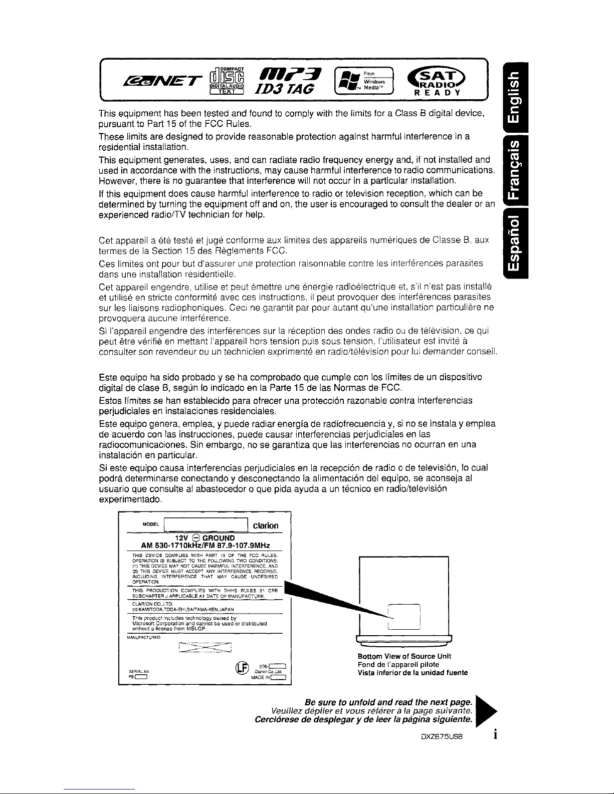
Bottom ViewofSource Unit
Fond
de
rappareil pilote
Vista inferior
de
la unidad fuente
Be sure to unfoldandread the nextpage.
~
Veuillez depUeretvous
nHerer
a
fa
page
suivante.
Cerciorese de desplegary de leerla paginasiguiente.
DXZ675USB i
Page 3
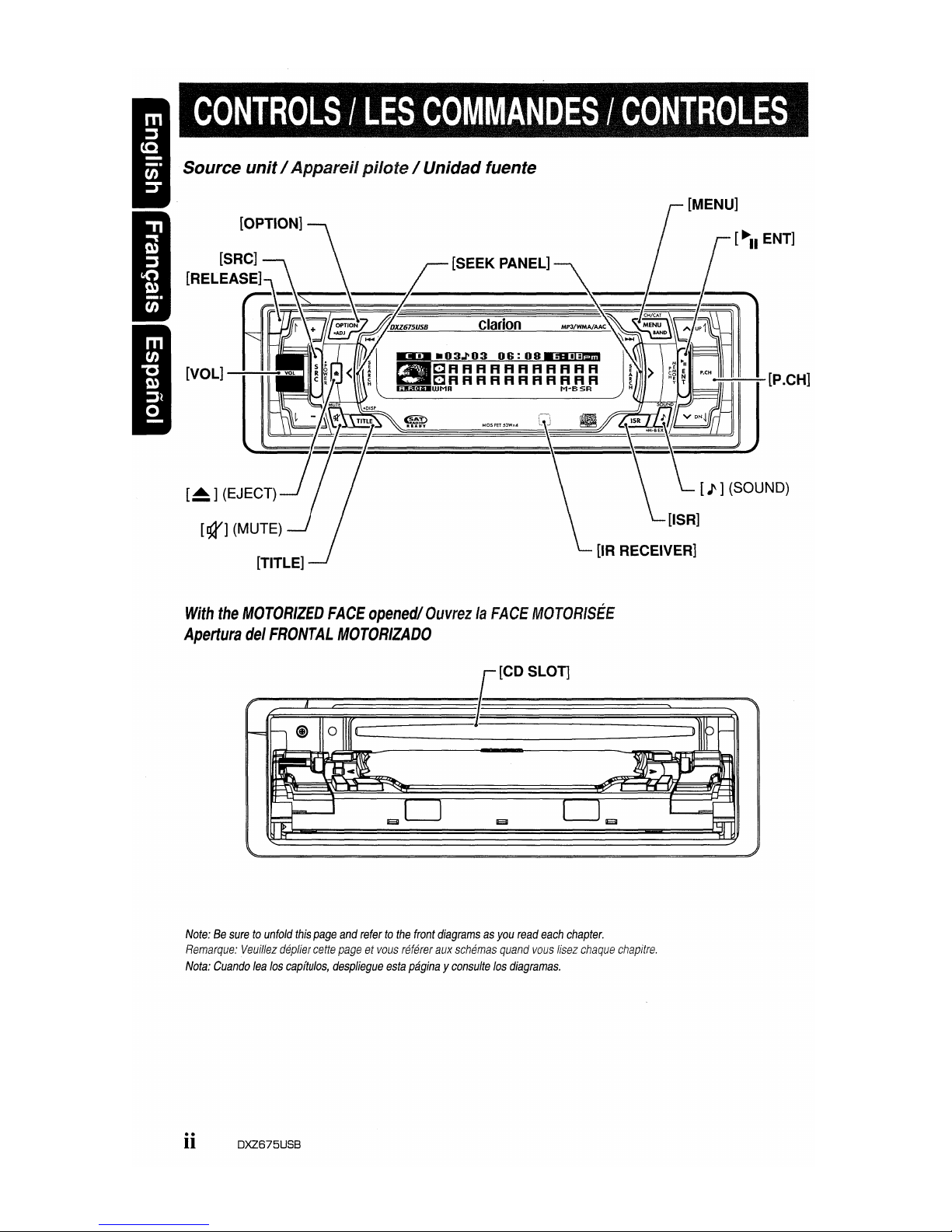
[~]
(EJECT)
[TITLE]
With
the
MOTORIZED
FACE
opened/
OuvrezlaFACE
MOTOR/SEE
Apertura
del
FRONTAL
MOTORIZADO
[~II
ENT]
Note:Besuretounfold
this
page
and
refertothe
front
diagramsasyou
read
each
chapter.
Remarque:
Veuillez
deplier
cette
pageetvous
referer
aux
schemas
quand
vous
Ifsez
chaque
chapitre.
Nota:
Cuando
lea
los
capftulos,
despliegue
esta
paginayconsulte
los
diagramas.
ii DXZ675USB
Page 4
CLARION
PRODUCT
REGISTRATION INFORMATION
For USA and Canada only
www.clarion.com
Dear Customer:
Congratulations
on
your purchase of a Clarion mobile electronic products. We are
confident that you'll enjoy your Clarion experience.
There are many benefits to registering your product. We invite you to visit ourwebsite at
I www.clarion.com to register your Clarion product.
I
We have made product registration simple with our easy to use website. The registration
form
is
short and easy to complete. Once you're registered, we can keep you informed of
~
important product information.
lRegister at www.clarion.com - it's easyto keep your Clarion product up to date.
INFORMATIONS
DE
L'ENREGISTREMENT
DE
PRODUITS
CLARION
Pour les Etas Unis etIeCanada seulement
www.clarion.com
Cher client:
Nous vous remercions d'avoir achete ce produit electronique mobile Clarion. Nous
sommes confiants que vous apprecierez votre experience Clarion.
II
y a beaucoup d'avantage aenregistrer votre produits. Nous vous invitons avisiter notre
site Web
www.clarion.com pour enregistrervotre produit Clarion.
Nous avons facllite la tache d'enregistrement de produit simple et facile grace
anotre
site Web. Le formulaire d'enregistrement est court et facile
acompleter. Lorsque vous
etes enregistrer, nous pouvons
vous
tenir informe des informations important de produits.
Enregistrer
awww.clarion.com - c'est facile de mettre ajour votre produit Clarion.
INFORMACION DEL REGISTRO
DE
PRODUCTO
DE
CLARION
Para USA YCanada nomas
www.clarion.com
Querido Cliente:
Felicitaciones por
su
compra de producto electranico mavil de Clarion. Estamos seguros
que usted gozara de
su
experiencia conelproducto de Clarion.
Hay muchas ventajas
al
registrarsuproducto. Le invitamos a que visite nuestro sitio
en
internet www.clarion.com para registrarsuproducto de Clarion.
Hemos hecho
el
registro de producto facilennuestro sitio. La forma de registro es corta
y
fadl
de completar. Una vez que10registre, podremos proporcionarle la informacion de
su
producto.
Registrese
en
www.clarion.com -
es
facil mantenersuproducto de Clarion actualizado.
iii DXZ675USB
Page 5
I
Thank you for purchasing this Clarion product.
* Please read this owner's manual
in
its
entirety before operating this equipment.
* After reading this manual,
be
suretokeepitin
a handy place (e.g., glove compartment).
* Check the contents of the enclosed warranty card and keep
it
carefully with this manual.
*'
This manual includes the operating procedures of the iPod® interface, CD/DVD changer, Satellite
Radio Receiver and TV tuner connected via the CeNET cable. The iPod interface, CD/DVD changer
and TV tuner have their own manuals, but
no
explanations for operating them are described.
"iPod" is a trademark of Apple Computer, Inc., registered
in
the U.S. and other countries.
Contents
CONTROLS ii
1. FEATURES 1
2. PRECAUTIONS 2
Motorized Face 2
Handling Compact Discs 3
3.
NOMENCLATURE 4
Names of the Buttons and Their Functions 4
Display Items 5
LCD Screen 5
4. DCP 6
5.
REMOTE CONTROL 7
Inserting the Battery 7
Functions of Remote Control Unit Buttons 8
6.
OPERATIONS 10
Basic Operations 10
Radio Operations 14
CD/MP3IWMAlAAC Operations 16
Operations Common to Each Mode
20
7.
OPERATIONS OF ACCESSORIES 24
USB Operations
24
iPodBBOperations
26
Satellite Radio Operations
28
CD
Changer Operations
30
DVD Changer Operations
31
TV Operations 32
8.
IN
CASE OF DIFFICULTV 33
9.
ERROR DISPLA
VS
35
10. SPECIFICATIONS 36
• Motorized Full Dot LCD with SLiDETRAK
• 6ch/6V RCA Output / 53W X 4 Built-in MOSFET Amplifier
• Built-in LPF/HPF
DXZ675USB
1
Page 6
When the inside of the car is very cold and
the player is used soon after switching on the
heater moisture may form
on
the disc or the
optical parts of the player and proper
playback may not be possible. If moisture
forms on the disc, wipe it off with a softcloth.
If moisture forms on the optical parts of the
player, do not use the player for about one
hour. The condensation will disappear
naturally allowing normal operation.
2.
Driving on extremely bumpy roads which
cause severe vibration may cause the sound
to skip,
3.
This unit uses a precision mechanism. Even
in
the event that trouble arises, never open
the case, disassemble the unit, or lubricate
the rotating parts.
Motorized Face
ACAUTION
USE OF CONTROLS, ADJUSTMENTS, OR
PERFORMANCE OF PROCEDURES OTHER
THAN THOSE SPECIFIED HEREIN, MAY
RESULT IN HAZARDOUS RADIATION
EXPOSURE.
THE COMPACT DISC PLAYER SHOULD NOT
BE ADJUSTED OR REPAIRED BY ANYONE
EXCEPT PROPERLY QUALIFIED SERVICE
PERSONNEL.
CHANGES OR MODIFICATIONS
NOT
EXPRESSLY APPROVED BY THE
MANUFACTURER
FOR
COMPLIANCE
COULD VOID THE USER'S AUTHORITY TO
OPERATE THE EQUIPMENT.
INFORMA
nON
FOR USERS:
CHANGES OR MODIFICATIONS TO THIS
PRODUCT NOT APPROVED BY THE
MANUFACTURER WILL VOID THE
WARRANTY AND WILL VIOLATE FCC
APPROVAL.
This unit uses motorized face to make large-screen displays possible.
When you use the motorized face,
be
sure to close
it
A CAUTION
BE CAREFUL NOTTO GET YOUR FINGERS
CAUGHT WHEN OPENING AND CLOSING
THE MOTORIZED FACE.
1.
For safety's sake, always close the
MOTORIZED FACE before leaving this unit
unused for a prolonged period or switching
OFF the ignition key.
If you switch OFF the ignition key with the
MOTORIZED FACE tilted, the MOTORIZED
FACE does not close.
2.
Before the MOTORIZED FACE closes, there
may be a braking sound from the safety
mechanism. This is normal.
2 OXZ675USB
3.
If you move the MOTORIZED FACE by
hand, this may create play. To correct this
play, with the power on forthe unit, press the
[~]
button to close the MOTORIZED FACE.
4.
After a disc is ejected, the MOTORIZED
FACE automatically returns to the tilted or
closed state. If there is any obstruction when
the MOTORIZED FACE tries to close, the
safety mechanism is triggered and the
MOTORIZED FACE returns to the open
state.
If this happens, remove the
obstruction, then press the
[~]
button.
5.
To avoid scratching the compact disk, keep
the CD level when inserting or removing
them.
Page 7
Handling Compact Discs
Use only compact discs bearing the
~n~~
or
ffilm~~
mark.
[G'fE'><t'j
Do
not play heart-shaped, octagonal, or other
specially shaped compact discs.
Some CDs recorded
in
CD-R/CD-RW mode
may not be usable.
Handling
• Compared to ordinary music CDs, CD-R and
CD-RW discs are both easily affected by high
temperature and humidity and some of CD-R
and CD-RW discs may not be played.
Therefore, do not leave them for a long time
in
the car.
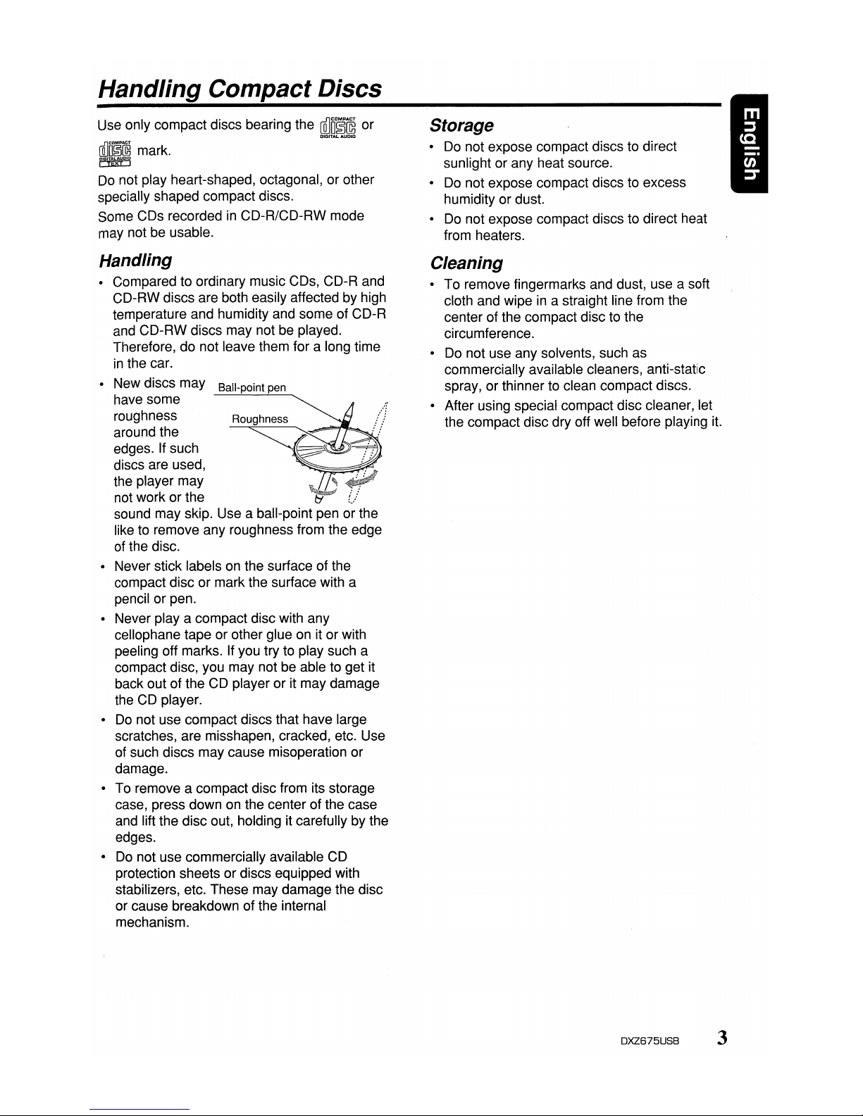
• New discs may
Ball-point pen
have some
roughness
Roughness
around the
edges. If such
discs are used,
the player may
not work or the
sound may skip. Use a ball-point pen or the
like to remove any roughness from the edge
of the disc.
• Never stick labels on the surface of the
compact disc or mark the surface with a
pencil or pen.
• Never
playa
compact disc with any
cellophane tape or other glue on it or with
peeling off marks. If you try to play such a
compact disc, you may not be able to get it
back out of the CD player or it may damage
the CD player.
•
Do
not use compact discs that have large
scratches, are misshapen, cracked, etc. Use
of such discs may cause misoperation or
damage.
• To remove a compact disc from its storage
case, press down on the center of the case
and lift the disc out, holding it carefully by the
edges.
•
Do
not use commercially available CD
protection sheets or discs equipped with
stabilizers, etc. These may damage the disc
or cause breakdown of the internal
mechanism.
Storage
• Do not expose compact discs to direct
sunlight or any heat source.
•
Do
not expose compact discs to excess
humidity or dust.
•
Do
not expose compact discs to direct heat
from heaters.
Cleaning
To remove fingermarks and dust, use a soft
cloth and wipe
in
a straight line from the
center of the compact disc to the
circumference.
Do not use any solvents, such as
commercially available cleaners, anti-static
spray, or thinner to clean compact discs.
After using special compact disc cleaner, let
the compact disc dry off well before playing
it.
DXZ675USB
3
Page 8
Note:
• Be sure to read this chapterreferringtothe front diagramsofchapter "CONTROLS" on page ii (unfold).
Names
of
the Buttons
and
Their Functions
[RELEASE] button
• Deeply pushinthe button to unlock the DCP.
[SRC] button
• Press the button to turn on the power.
• Press and hold the button for 1 second or
longer to turn off the power.
• Switch the operation mode among the radio
mode, etc.
[OPTION] button
• Press the button to enter the option mode.
• Press and hold the button for 1 second or
longer to enter the adjust mode.
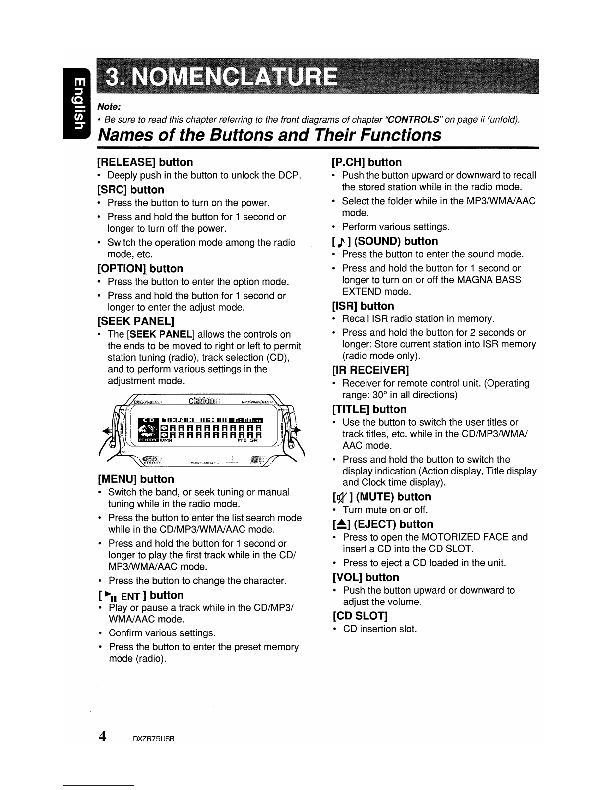
[SEEK PANEL]
• The [SEEK PANEL] allows the controls on
the ends to be moved to right or left to permit
station tuning (radio), track selection (CD),
and to perform various settings
in
the
adjustment mode.
[MENU] button
• Switch the band, or seek tuning or manual
tuning while
in
the radio mode.
• Press the button to enter the list search mode
while
in
the CD/MP3IWMAlAAC mode.
• Press and hold the button for 1 second or
longer to play the first track while
in
the COl
MP3/WMAlAAC mode.
• Press the button to change the character.
[~II
ENT]
button
• Play or pause a trackwhileinthe
CD/MP31
WMAlAAC mode.
• Confirm various settings.
• Press the button to enter the preset memory
mode (radio).
[P
.CH] button
• Push the button upward or downward to recall
the stored station while
in
the radio mode.
• Select the folder while
in
the MP3IWMAlAAC
mode.
• Perform various settings.
[J]
(SOUND) button
• Press the button to enter the sound mode.
• Press and hold the button for 1 second or
longer to turn on or off the MAGNA BASS
EXTEND mode.
[ISR] button
•
RecalliSR
radio stationinmemory.
• Press and hold the button for 2 seconds or
longer: Store current station into ISR memory
(radio mode only).
[IR RECEIVER]
• Receiver for remote control unit. (Operating
range: 30°
in
all directions)
[TITLE] button
• Use the button to switch the user titles or
track titles, etc. while
in
the CD/MP3/WMAI
AAC mode.
• Press and hold the button to switch the
display indication (Action display, Title display
and Clock time display).
, [gr] (MUTE) button
• Turn mute on or off.
[~]
(EJECT) button
• Press to open the MOTORIZED FACE and
insert a CD into the CD SLOT.
• Press to eject a CD loaded
in
the unit.
[VOL] button
• Push the button upward or downward to
adjust the volume. .
[CD SLOT]
• CD insertion slot.
4
DXZ675USB
Page 9
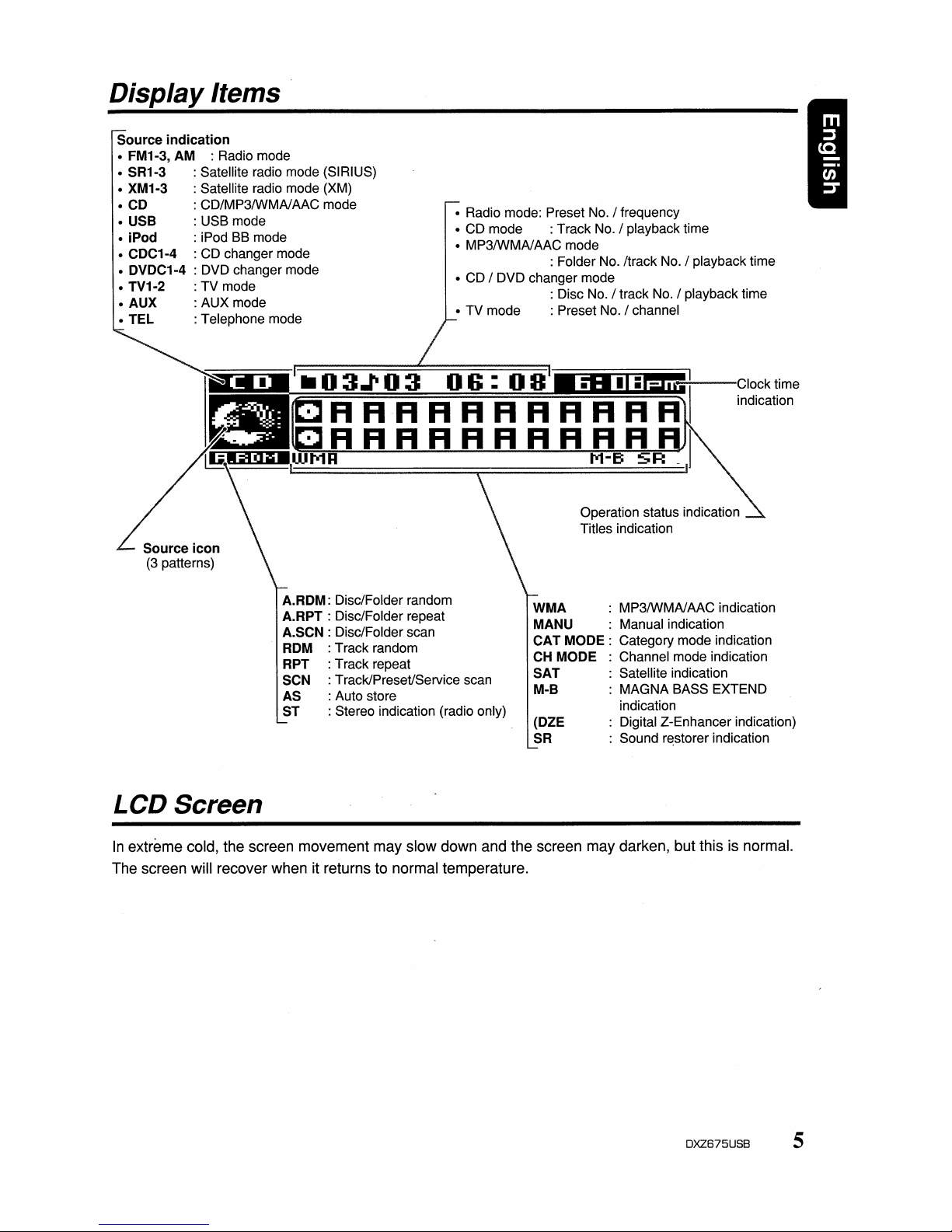
DisplayItems
Source indication
• FM1-3, AM : Radio mode
• SR1-3 : Satellite radio mode (SIRIUS)
• XM1-3 : Satellite radio mode (XM)
• CD : CD/MP3IWMAlAAC mode
• USB : USB mode
• iPod : iPod BB mode
• CDC1-4 : CD changer mode
• DVDC1-4 : DVD changer mode
• TV1-2 : TV mode
• AUX : AUX mode
•
TEL
: Telephone mode
• Radio mode: Preset No. / frequency
• CD mode : Track No. / playback time
• MP3IWMAlAAC mode
: Folder No. /track No. / playback time
• CD / DVD changer mode
: Disc No. / track No. / playback time
• TV mode : Preset No. / channel
~~r;;-==::iiiiiiii.r=;::~~~~~~===~~~~nolii~~ilm~~~ii!i!
.LjJ~--Clock
time
indication
Operation status indication
Titles indication
Source icon
(3
patterns)
(DZE
SR
LCD Screen
A.RDM: Disc/Folder random
A.RPT : Disc/Folder repeat
A.SCN : Disc/Folder scan
ROM : Track random
RPT : Track repeat
SCN :Track/Preset/Service scan
AS : Auto store
ST : Stereo indication (radio only)
WMA
: MP3IWMAlAAC indication
MANU : Manual indication
CAT
MODE:
Category mode indication
CH MODE : Channel mode indication
SAT
: Satellite indication
M-B : MAGNA BASS EXTEND
indication
: Digital Z-Enhancer indication)
: Sound
r~storer
indication
5
In
extreme cold, the screen movement may slow down and the screen may darken, but this is normal.
The screen will recover when it returns to normal temperature.
DXZ675USB
Page 10
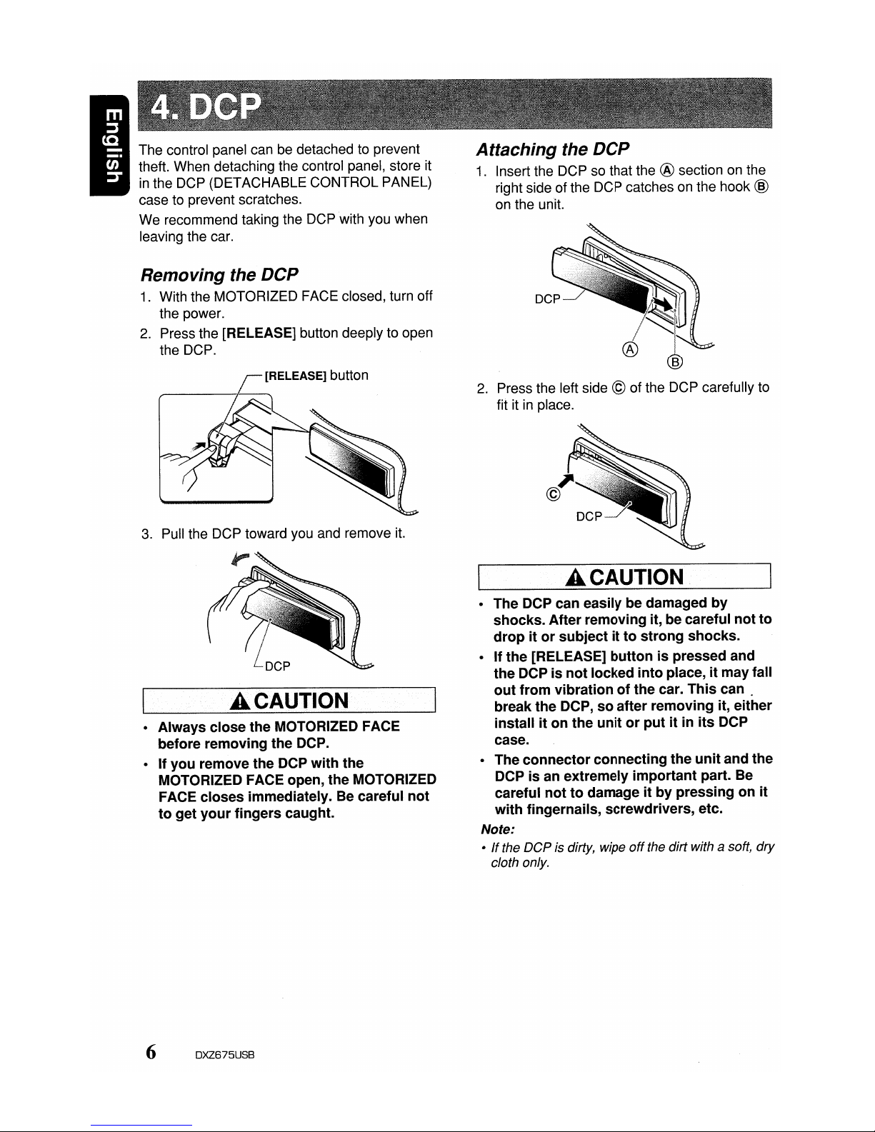
The control panel can be detached to prevent
theft. When detaching the control panel, store it
in
the DCP (DETACHABLE CONTROL PANEL)
case to prevent scratches.
We recommend taking the DCP with you when
leaving the car.
Removing the
DCP
1.
With the MOTORIZED FACE closed, turn off
the power.
2.
Press the [RELEASE] button deeply to open
the DCP.
3.
Pull the DCP toward you and remove it.
A CAUTION
• Always close the MOTORIZED FACE
before removing the DCP.
• If you remove the DCP with the
MOTORIZED FACE open, the MOTORIZED
FACE closes immediately. Be careful not
to get your fingers caught.
6 DXZ675USB
Attaching the
DCP
1.
Insert the DCP so that the ® section on the
right side of the DCP catches on the hook
@
on the unit.
2.
Press the left side © of the DCP carefully to
fit it
in
place.
A CAUTION
• The DCP can easily be damaged by
shocks. After removing it, be careful not to
drop it or subject it to strong shocks.
• If the· [RELEASE] button is pressed and
the DCP is not locked into place, it may fall
out from vibration of the car. This
can.
break the DCP, so after removing it, either
install it on the unit or put it in its DCP
case.
• The connector connecting the unit and the
DCP is an extremely important part. Be
careful not to damage it by pressing on it
with fingernails, screwdrivers, etc.
Note:
•Ifthe
DCP
is dirty, wipe
off
the dirt with a soft,
dry
cloth only.
Page 11
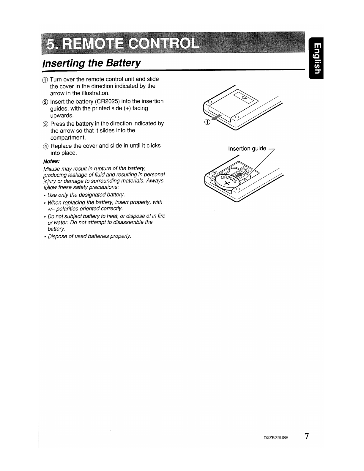
CD
Turn over the remote control unit and slide
the cover in the direction indicated by the
arrow in the illustration.
® Insert the battery (CR2025) into the insertion
guides, with the printed side
(+)
facing
upwards.
® Press thebattery in the direction indicated by
the arrow so that it slides into the
compartment.
@ Replace the cover and slide in until it clicks
into place.
Notes:
Misuse
may
result in ruptureofthe battery,
producing leakage
of
fluid
and
resulting in personal
injury
or
damage to surrounding materials. Always
follow these safetyprecautions:
•
Use
only the designatedbattery.
•
When
replacing the battery, insert properly, with
+/-
polarities oriented correctly.
•
Do
notsubject batteryto heat,ordisposeofin fire
or water. Do notattempt
to
disassemble the
battery. .
• Disposeofusedbatteries properly.
Insertion guide
DXZ675USB 7
Page 12
[!],[']
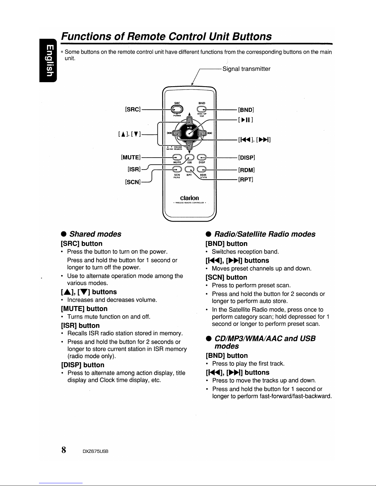
Functions
of
Remote Control Unit Buttons
*Some buttons
on
the remote control unit have different functions from the corresponding buttons on the main
unit.
/ Signal transmitter
--------
~
SBC
"ND
1
[SRC]----;I~I
Q A
~~II--[BND]
~:---[~II]
II
~
~~--:-:-II-[~~],
[~~]
W~~
,
II
[MUTE]--~II-~9
~~II--[DISP]
[ISR]J
(
II
~
~
II
[ROM]
[SCN]--.J
PS!AS
_V/V_TR
----io+---[RPT]
Clarion
• Shared modes
[SRC] button
• Press the button to turn on the power.
Press and hold the button for 1 second or
longer to turn off the power.
• Use to alternate operation mode among the
various modes.
L"],
[T]
buttons
• Increases and decreases volume.
[MUTE] button
• Turns mute function on and off.
[ISR] button
• Recalls ISR radio station storedinmemory.
• Press and hold the button for 2 seconds or
longer to store current station
in
ISR memory
(radio mode only).
[DISP] button
• Press to alternate among action display, title
display and Clocktime display, etc.
8 DXZ675USB
• Radio/Satellite Radio modes
[BND] button
• Switches reception band.
[~...-],
[~~]
buttons
• Moves preset channels up and down.
[SCN] button
• Press to perform preset scan.
• Press and hold the button for 2 seconds or
longer to perform auto store.
•
In
the Satellite Radio mode, press once to
perform category scan; hold depressed for 1
second or longer to perform preset scan.
• CD/MP3/WMA/AAC
and
USB
modes
[BND] button
• Press to play the first track.
[~...-],
[~]
buttons
• Press to move the tracks.up and down.
• Press and hold the button for 1 second or
longer to perform fast-forward/fast-backward.
Page 13
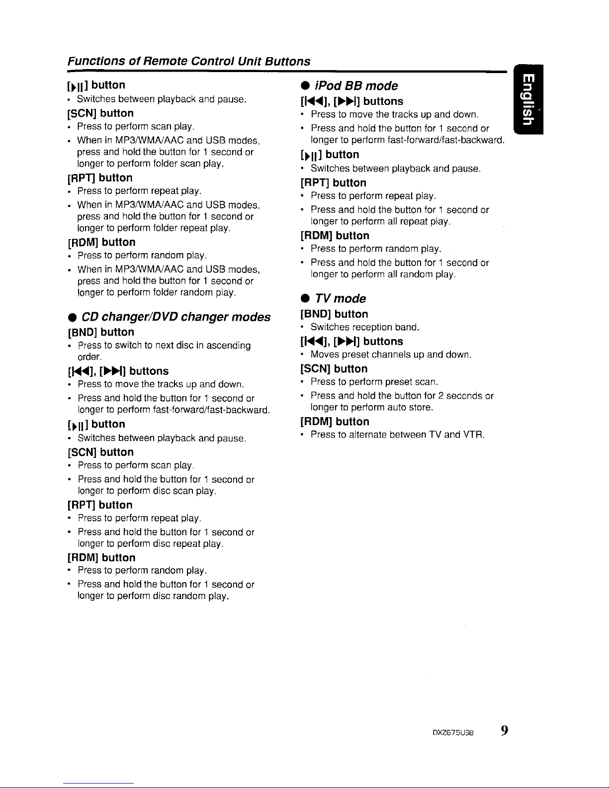
FunctionsofRemote Control Unit Buttons
[~II]
button
• Switches between playback and pause.
[SeN] button
• Press to perform scan play.
• WheninMP3/WMAlAAC and USB modes,
press and hold the button for 1 second or
longer to perform folder scan play.
[RPT] button
• Press to perform repeat play.
• When
in
MP3IWMAlAAC and USB modes,
press and hold the button for 1 second or
longer to perform folder repeat play.
[ROM] button
• Press to perform random play.
• WheninMP3/WMAlAAC and USB modes,
press and hold the button for 1 second or
longer
to
perform folder random play.
•
CD
changer/DVD changer modes
[BND] button
• Press to switch to next discinascending
order.
[
....
<tlII],[...
H] buttons
Press to move the tracksupand down.
• Press and hold the button for 1 second or
longer to perform fast-forward/fast-backward.
[~II]
button
• Switches between playback and pause.
[SeN] button
• Press to perform scan play.
• Press and hold the button for 1 second or
longer
to
perform disc scan play.
[RPT]
button
• Press to perform repeat play.
• Press and hold the button for 1 second or
longer
to
perform disc repeat play.
[ROM] button
• Press to perform random play.
• Press and hold the button for 1 second or
longer to perform disc random play.
• iPod BBmode
[1<llIII
....
],
[..-H] buttons
• Press to move the tracks up and down.
• Press and hold the button for 1 second or
longer to perform fast-forward/fast-backward.
[~II]
button
• Switches between playback and pause.
[RPT] button
• Presstoperform repeat play.
• Press and hold the button for 1 second or
longer to perform all repeat play.
[ROM] button
• Presstoperform random play.
• Press and hold the button for 1 second or
longer to perform all random play.
•
TVmode
[BND] button
• Switches reception band.
[1<llIII"'],
[..-H] buttons
• Moves preset channels up and down.
[SeN] button
• Press to perform preset scan.
• Press and hold the button for 2 seconds or
longer
to
perform auto store.
[ROM] button
• Press to alternate between TV and VTR.
I
DXZ675USB 9
Page 14
I
Note:
• Be sure to read this chapterreferringtothe front diagramsofchapter "CONTROLS" on page if (unfold).
Basic Operations
A CAUTION
Be
suretolower
the
volume
before
switching
off
the
unit
powerorthe
ignition
key. The
unit
remembers
its
last
volume
setting.Ifyou
switch
the
power
off
with
the
volume
up,
when
you
switch
the
power
back
on,
the
sudden
loud
volume
may
hurt
your
hearing
and
damage the unit.
Turning
on/off
the
power
Note:
• Be careful about using this unit for a long time
without running the engine. If you drain the car's
battery too
far,
you maynotbe able to start the
engine
and
this can reduce the service lifeofthe
battery.
1. Press the [SRC] button.
The mode that was previous active
is
displayed.
2. Press and hold the [SRC] button for 1
second or longertoturn off the power for the
unit.
Note:
•
The
first time this unit is turned on after the wire
connections are completed, it mustbe checked
what equipment
is
connected. When the
power
is
turned on, "SYSTEM CHECK" appears in the
display, then the unit returns
to
the clock display
mode. The system check starts within the unit.
When the system check
is
complete, press the
[SRCj button again.
Selecting a mode
1.
Press the (SRC] button to change the
operation mode.
2.
Each time you press the [SRC] button, the
operation mode changes
in
the following
order:
Radio
~
(Satellite radio)~CD/MP3/WMAJ
AAC
~
USB~(iPod
BB)~(CD changer)
~
(DVD changer)~(TV)~AUX~Radio
...
*External equipment not connected with
CeNET is not displayed.
10 DXZ675USB
Adjusting
the volume
1.
Push the [VOL] button upward or downward
to
adjust the volume.
* The volume level is from 0
(minimum)
to
33
(maximum).
SWitching the
display
Press and hold the [TITLE] button for 1 second
or longer to select the desired display.
• When
the
poweristurned
on
1.
Each time you press and hold the [TITLE]
button
for 1 second or longer, the display
switches
in
the following order:
Action display
~
Title display~Clock time
display
~
Action display
...
• When
the
poweristurned
off
1.
Each time you press the [TITLE] button, the
clock time appears or disappears
in
the
d"isplay.
Page 15
Basic Operations
Adjusting
MAGNA BASS EXTEND
The MAGNA BASS EXTEND does not adjust
the low sound area like the normal sound
adjustment function, but emphasizes the deep
bass sound area to provide you with a dynamic
sound.
1.
Press and hold the [J ]button for 1 second
or longer to turn on the MAGNA BASS
EXTEND effect. "M-B" lights
in
the display.
2.
Press and hold the [J ]button for 1 second
or longer to turn off the MAGNA BASS
EXTEND effect. "M-B" goes off from the
display.
*The adjustment can only be performed when
the DZE is set to "DZE OFF".
*The factory default setting is off.
Mute
Use
this function to turn off the sound
immediately.
1.
Press the
[g3I]
button.
The sound turns off and "MUTE" blinks
in
the
display.
2.
Press the
[g3I]
button again to cancel the
mute mode.
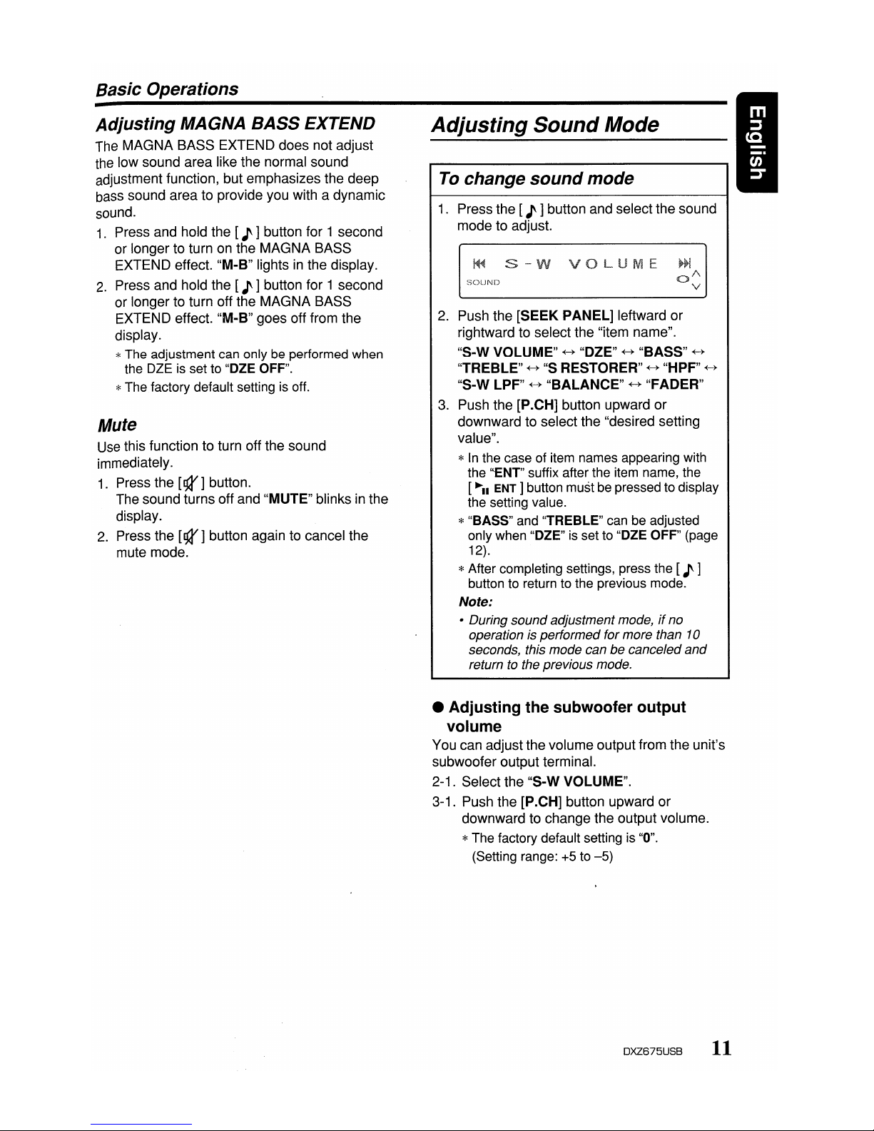
Adjusting
Sound
Mode
To change
sound
mode
1.
Press the [J ]button and select the sound
mode to adjust.
~~
s-w
va
UM
SOUND
2.
Push the [SEEK PANEL] leftward or
rightward to select the "item name".
"S-W VOLUME"
~
"DZE"~"BASS"
~
"TREBLE"
~
"s
RESTORER"~"HPF"
~
"S-W LPF"~"BALANCE"~"FADER"
3.
Push the [P.CH] button upward or
downward to select the "desired setting
value".
*
In
the case of item names appearing with
the '''ENT'' suffix after the item name, the
[~II
ENT]
button must be pressed to display
the setting value.
*"BASS" and "TREBLE" can be adjusted
only when "DZE" is set to "DZE OFF" (page
12).
*After completing settings, press the [J ]
button to return to the previous mode.
Note:
• During sound adjustment mode,ifno
operation is performedformore than
10
seconds, this mode can be canceled
and
returntothe previous mode.
• Adjusting the subwoofer output
volume
You can adjust thevolume output from the unit's
subwoofer output terminal.
2-1. Select the "S-W VOLUME".
3-1. Push the [P.CH] button upward or
downward to change the output volume.
*The factory default setting is "0".
(Setting range: +5 to
-5)
DXZ675USB
11
Page 16

Basic Operations
Q
curve:
20
~
Q
curve:
1
• Adjusting the bass
The
bass gain, bass FREQ (center frequency)
and bass Q can be adjusted as follows.
The
adjustment can only be performed when
the OZE is set to "DZE OFF".
2-1. Select "BASS".
2-2. Press the
[~II
ENT]
button.
2-3. Push the
[SEEK
PANEL]
leftward or
rightward and select from:
"BASS
GAIN"
+-+
"BASS
FREQ"
+-+
"BASSQ"
Center
Frequency
Frequency (F) (Hz)
~FreqUency
curve
Level
(dB)
Gain
• Q curve
The
Q curve becomes sharper when the
numerical value is increased, and smoother
when the numerical value is decreased.
Flat frequency characteristics can be made by
selecting a Q curve opposite to that of the curve
to be compensated.
• Compensationoffrequency
characteristics
The
figure below
shows
the relationship
between the center frequency, gain and Q
curve.
: no sound effect
: Suitable for genuine speakers
: Suitable for separate
speakers
DZE
3 : Suitable for co-axial speakers
3-3.
When
the "DZE 1", "DZE 2"or"DZE 3" is
set, push the [P .CH] button upward
or
downward to change the OZE level from +3
to-3.
*The factory default setting is "0".
3-4. Press the
[~II
ENT]
button to return to the
previous mode.
• Compensation
There is no need to compensate frequency
characteristics if they are flat (no peaks
or
valleys)
when
you have measured the
frequency characteristics with a measuring
device. However, sometimes the frequency
characteristics rise
or
fall in
some
places. If this
happens, the frequency characteristics
must
be
compensated. Create a frequency curve having
characteristics that are opposite to the center
frequency
of
parts where the characteristics rise
and fall to cancel out these peaks and values,
and make the frequency characteristics as flat
as possible.
Making the frequency characteristics as flat as
possible is called "Compensation".
• Setting the Digital Z-Enhancer
This unit are provided with 3 types of sound
tone effects stored in memory. Select the one
you prefer.
*The factory default setting is "OZE OFF".
2-1. Select the "DZE".
3-1. Press the
[~II
ENT]
button.
3-2. Push the
[SEEK
PANEL]
leftward
or
rightward to selectthe tone effect. Eac'h
time you pushthe
[SEEK
PANEL],
the tone
effect changes in the following order:
"DZE
OFF"
+-+
"DZE 1"
+-+
"DZE 2"
+-+
"DZE
3"
DZE
OFF
DZE
1
DZE2
12
DXZ675USB
Page 17

Basic Operations
3-1.
Push
the
[P.CH] button upward
or
downward
to adjust the gain,
the
FREQ
(center frequency)
and
the Q.
BASS
GAIN:
+7 to-7(The factory default
setting is
"a")
BASS
FREQ:
50Hz/80Hz/120Hz
(The
factory default setting is "50")
BASS
Q: 1/1.25/1.5/2 (The factory default
setting is "1")
3-2.
Press
the[.......
ENT]
button to return to
the
previous mode.
• Adjusting the treble
The
treble gain and treble
FREQ
(center
frequency) can
be
adjusted as follows.
The
adjustment can
onlybeperformed
when
the
OlE
is set to "OZE OFF".
2-1. Select
"TREBLE".
2-2. Press
the[.......
ENT
Ibutton.
2-3. Push
the
[SEEK
PANEL]
leftward
or
rightward and select from:
"TREB
GAIN"
«-+
"TREB
FREQ"
3-1. Push
the
[P.CH]
button upward or
downward to
adjust
the gain and
FREQ
(center frequency).
TRES
GAIN:
+6 to
-6
(The factory default
setting is "0")
TREB
FREQ:
8KHz/12KHz
(The
factory
default setting is "12K")
3-2. Press the [
.......
ENT]
buttontoreturn to the
previous mode.
• Adjusting the sound restorer
The sound restorer enriches the
playbackofall
types of music files that have
undergone
any
level of
data
compression.
2-1. Select "S RESTORER".
3-1.
Push
the
[P.CH]
button upward or
downward
to adjust.
Each time you push the [P.CH] button,
the
sound restorer
changesinthe
following
order:
"OFF"
«-+ "1" «-+ "2" «-+ "3"
*The factory default setting is "OFF".
Set this
adjustment
in accordance with the
music source used
OFF:
For
musIc sources
compressed
at
high bit rate
1: For music
sources
compressed
for high I
quality at
low
bit rate •
2:
For
music
sources
compressed
for
standard quality
at
low
bit rate
3: For
music
sources
compressed
for
low
quality at low bit rate
• Setting high pass
filter
2-1. Select "HPF".
3-1. Push the [P.CH] button upward
or
downward
to select
the
setting.
Each
time
you push the [P.CH] button,
the
setting
changesinthe
following order:
"THRGH"
«-+ "50Hz" «-+ "80Hz" «-+ "120Hz"
*The factory default setting
is
"THRGH"
(through).
• Setting low pass
filter
2-1. Select
"S-W
LPF".
3-1. Push
the
[P.CH} button upward
or
downward
to select
the
setting.
Each time you push
the
[P.CH] button, the
setting
changesinthe
following order:
"THRGH"
«-+ "50Hz" «-+ "80Hz" «-+ "120Hz"
*The factory default setting is "THRGH"
(through).
• Adjusting the balance
2-1. Select
"BALANCE".
3-1. Push
the
[P.CH} button upward
to
emphasize
the
sound from
the
right
speaker, push
the
button
downward
to
emphasize
the
sound from the left speaker.
*The factory default setting
is
"0".
(Adjustment range: L12 to R12)
• Adjusting the fader
2-1. Select
"FADER".
3-1. Push
the
[P.CH] button upward to
emphasize
the
sound from
the
front
speaker, push the button
downward
to
emphasize
the
sound from
the
rear
speaker.
*The factory default setting
is
"0".
(Adjustment range: R12
to
F12)
DXZ675USB 13
Page 18

I
Radio Operations
Listening to the radio
1.
Press the [SRC] button and select the radio
mode. The frequency appears
in
the display.
2.
Press the [MENU] button and select the
radio band. Each time the button is pressed,
the radio reception band changes
in
the
following order:
FM1~FM2~FM3
....
AM
....
FM1
...
3. Push the [SEEK PANEL] leftward or
rightward to tune
in
the desired station.
Tuning
There are 3 types of tuning mode available,
seek tuning, manual tuning and preset tuning.
Seek
tuning
1.
Press the [MENU] button and select the
desired band (FM or AM).
2.
Tune into a station.
*If "MANU"
is
litinthe display, press
and
hold
the [MENU] button for 1second or longer.
"MANU"
in
the display goes off and seek
tuning
is
now available.
When the [SEEK PANEL] is pushed rightward,
the station is sought in the direction of higher
frequencies; if the [SEEK PANEL] is pushed
leftward, the station is sought
in
the direction of
lower frequencies.
Manual tuning
There are 2 ways available: Quicktuning and
step tuning.
When you are
in
the step tuning mode, the
frequency changes one step at a time.
In
the
quick tuning mode, you can quickly tune the
desired frequency.
1.
Press the [MENU] button and select the
desired band (FM or AM).
*
If
"MANU"isnot litinthe display, press
and
hold the [MENU] button for 1second or
longer. "MANU"
is
lit
in
the display and manual
tuning is now available.
2.
Tune into a station.
14 DXZ675USB
•
Quick
tuning
Push the
[SEEK
PANEL] leftward or rightward
and hold
in
position for 1 second or longer
to
tuneina station.
• Step
tuning
Push the
[SEEK
PANEL] leftward or rightward
to manually tune in a station.
Recalling a presetstation
A total of 24 preset positions (6-FM1, 6-FM2, 6FM3, 6-AM) exists to store individual radio
stations
in
memory. Pushing the [P.CH] button
upward or downward recalls the stored radio
frequency automatically.
1.
Press the [MENU] button and select the
desired band (FM or AM).
2.
Push the [P.CH] button upward ordownward
to recall the stored station.
*Press the [
..-
.. ENT ] buttontoenter the preset
memory mode. Push
the
[P.CH] button
upward or downward, then press
and
hold the
["-11
ENT]
button for 2 seconds or longer to
store that station into preset memory.
Manual memory
1.
Select the desired station with seektuning or
manual tuning.
2.
Press the
["'11
ENT ] button to enter the
preset memory mode.
3.
Push the [P.CH] button upward ordownward
to select a desired station, then press and
hold the [ .....
ENT]
button for 2 seconds or
longer to store the current station into preset
memory.
Page 19

Radio Operations
Auto
store
Auto storeisa function for storing up to 6
stations that are automatically tuned
in
sequentially.If6 receivable stations cannot be
received, a previously stored station remains
unoverwritten at the memory position.
1.
Press the [MENU] button and select the
desired band (FM or AM).
2.
Press the [OPTION] button.
3.
Push the [SEEK PANEL] leftward or
rightward
to
select "AUTO STORE".
4.
Press and hold the
[-"11
ENT]
button for 2
seconds or longer. The stations with good
reception are stored automatically to the
preset channels.
Preset
scan
Preset scan receives the stations stored
in
preset memoryinorder. This function is useful
when searching for a desired station
in
memory.
1.
Press the [OPTION] button.
2.
Push the [SEEK PANEL] leftward or
rightward to select "PRESETSeN".
3.
Press the
[-"11
ENT]
button.
*
When
a desired stationistuned
in,
press the
[-"11
ENT]
button
againtocontinue receiving
that station.
Instant
station
recall (ISR) I
•
Instant station recallisa special radio preset
that instantly accesses afavorite radio station at
a touch of a button. The ISR function even
operates with the unit
in
other modes.
elSR
memory
1.
Select the station that you wishtostore
in
ISR memory.
2.
Press and hold the [ISR] button for 2
seconds or longer.
e Recalling a
station
with
ISR
In
any mode, press the [ISR] button to turn
on
the radio function and tune the selected radio
station. "ISR" appears
in
the display. Press the
[ISR] button again to return
to
the previous
mode.
DXZ675USB
15
Page 20

CDIMP31WMAIAAC Operations
MP31WMAIAAC
WhatisMP3?
MP3 is an audio compression method and
classified into audio layer3 of MPEG standards.
This audio compression method has penetrated
into
PC
users and become a standard format.
This MP3 features the original audio data
compression to about 10 percent of its initial
size with a high sound quality. This means that
about 10 music CDs can be recorded on a CD-
R disc or CD-RW discto allow a long listening
time without having to change CDs.
WhatisWMA?
WMA is the abbreviation of Windows Media
Audio, an audio file format developed by
Microsoft Corporation.
Notes:
•
If
you
playa
file with DRM (Digital Rights
Management) for
WMA
remaining ON, no audio
is output(The
WMA
indicatorblinks).
• Windows MediaTM,
and
the Windows ® logo are
trademarks,
or
registered trademarksofMicrosoft
Corporation in the United States and/orother
countries.
• To disable
DRM
(Digital Rights
Management)
1.
When using Windows Media Player8,click
on
TOOLS'"
OPTIONS'"
COPY MUSIC
tab, then under
COpy
SETTINGS, unclick
the check box for PROTECT CONTENT.
Then, reconstruct files.
2.
When using Windows Media Player9,click
on TOOL
...
OPTIONS'"
MUSIC RECORD
tab, then under Recording settings, unclick
the Check box for RECORD PROTECTED
MUSIC. Then, reconstruct files.
Personally constructed WMA files are used
at your own responsibility.
WhatisAAC?
• AAC is an acronym for "Advanced Audio
Coding" and refers to the audio compression
method used with video compression
standards MPEG-2 and MPEG-4.
• AAC files composed with the following
conditions can be played:
- AAC files encoded with iTunes.
- iTunes Ver. 7.0 or earlier.
- File extension ".m4a" (".M4A")
16 DXZ675USB
• Tracks purchased at an iTunes Music store,
and copyright-protected files cannot be
played.
• When playing AAC files that include image
data, additional time may be required before
playback begins.
• Files may not play properly, depending on the
iTunes version under which an AAC file is
encoded.
Precautions when creating
MP31
WMAIAAC
disc
• Usable sampling rates and
bit
rates
1.
MP3: Sampling rate 8 kHz-48 kHz,
Bit rate 8 kbps-320 kbps / VBR
2.
WMA: Bit rate 32 kbps-192 kbps
3.
AAC: Sampling rate 8 kHz-48 kHz,
Bit rate 8 kbps-320 kbps / VBR
• File extensions
1.
Always add a file extension ".MP3" (.mp3),
".WMA" (.wma) or ".M4A" (.m4a) to MP3,
WMA or AAC file by using single byte letters.
If you add a file extension other than
specified or forget to add the file extension,
the file cannot be played.
2.
Files without MP3IWMAlAAC datawill not
play. The indication
"-
-:--"appearsinthe
play time display if you attempt to play files
without MP3IWMAIACC data.
• Logical format (File system)
1.
When writing MP3IWMAlAACfile on a CD-R
disc or CD-RWdisc, please select "IS09660
level
1,
2 orJOLIET or Romeo or APPLE
ISO" as the writing software format. Normal
play may not be possible if the disc is
recorded on another format.
2.
The folder name and file name can be
displayed as the title during MP3IWMAlAAC
play butthe title must be within 64 single
byte alphabetical letters and numerals
(including an extension).
3.
Do
not affix a name to a file inside a folder
having the same name.
• Folder structure
1.
A disc with a folder having more than 8
hierarchical levels will be impossible.
Page 21

CDIMP31WMAI
AAC
Operations
• Numberoffilesorfolders
1.
Up to 255 files can be recognized per folder.
Up to 510 files can be played.
2.
Tracks are playedinthe order that theywere
recorded onto a disc. (Tracks might not
always be played
in
the order displayed
on
the PC.)
3.
Some noise may occur dependingonthe
type of encoder software used while
recording.
Set the typeoffile to be
played
(multi-session function)
When a single disc holds both normal CD type
tracks and
MP3/WMNAAC
type tracks,. use this
command to select which type of track to play.
*Default setting is "CD".
• When only one type of track (either music CD
or MP3/WMNAAC)
is
recorded on a disc,
selecting eithertype will allow playbackof the
disc.
• When playing CCCD (copy-control CDs), set
to CD type.
1.
Press the [OPTION] button.
2.
Push the [SEEK PANEL] leftward or
rightward to select
"MULTI SESS".
3.
Push the [P.CH] button upward or downward
to select
"CD" or
"MP3".
The mixed mode is
switched between CD type or
MP3/WMN
AAC type.
•
CD
When playing music CD only.
• MP3
When playing music MP3/WMNAAC only.
4.
When setting is completed, remove the disc
and reinsert
it.
Disc-In-play function
As long as the ignition key is turned to the ON or
ACC position, this function allows you to turn the
power to the unit and start playing the disc
automatically when the disc
is
inserted even if
the power
is
not turned on.
Backup Eject function
You can eject a disc by pressing the
[~]
button
even if the engine key or ACC
is
at the OFF
position.
A CAUTIO",
When the disc is ejected, press the
[~]
button
to close the control panel. If the control panel
is left open, you will hear adouble beep, and
the control panel automatically closes.
1.
Press the
[~]
button.
The control panel opens.
2.
Press the
[~]
button.
The disc is ejected.
Note:
• Always close the MOTORIZED FACEafter
opening it
or
ejecting the
CD.
A CAUTION
• Be careful
nottocatch
your
hand
or
fingers while closing the MOTORIZED
FACE.
• Do
not
trytoput
your
handorfingers in
the
disc
insertion slot. Also never insert
foreign objects into the slot.
• Do
not
insert
discs
where adhesive comes
out
from cellophane tapeora rental
CD
label,ordiscs
with marks where
cellophane tape
or
rental
CD
labels were
removed. It maybe impossible
to
extract
these
discs
from the unit and they may
cause the
unittobreak down.
Listening to a
disc
alreadyloaded
in
the
unit
Press the [SRC] button to select the
CD/MP31
WMNAAC
mode.
When the unit enters the CD/MP3/WMNAAC
mode, play starts automatically.
If there is nodisc loaded, the indication
"NO
DISC"
appearsinthe title display.
DXZ675USB
17
Page 22

CDIMP3IWMAlAAC Operations
Loading
a
CD
1.
Press the
[~]
button. The MOTORIZED
FACE opens.
2.
Insert a CD into the center of the CD SLOT
with the labeled side facing up. The CD plays
automatically after loading.
Notes:
• Never insert foreign objects into theCDSLOT.
•
If
theCDis
not
inserted easily, there
may
be
anotherCDin the mechanismorthe unit
may
require service. COMPACT
• Discs
not
bearing the
~[~1
or
~~
mark
and
CD-ROMs cannot be
played
by
t IS unit.
• Some CDs recorded in CD-RICD-RWmode
may
not
be usable.
Pausing
play
1.
Press the
[~II
ENT]
button to pause play.
"PAUSE" appears
in
the display.
2.
To resume CD play, press the
[~II
ENT]
button again.
Displaying
CD
titles
This unit can display title data for CD-textlMP3/
WMAIAAC disc and user titles input with this
unit.
1.
Each time you press the [TITLE] button, the
title display changes
in
the following order:
• CD-TEXT
disc
Title
scan'"
User title (disc) CD-text title
(track)
...
CD-text title (disc) Artist
name'"
Title scan
'"
• MP3/WMA/AAC
disc
Title
scan'"
Track
...
Folder
...
Title TAG
...
Album
TAG'"
Artist
TAG'"
Title scan
'"
• TITLE SCAN
When the display is changed to the title scan
mode, all titles of the track scroll automatically.
When
"AUTO SCROLL"
is
set "ON", the title
scan automatically. When
"AUTO SCROLL" is
set
"OFF", the title only scan one time. (The
factory default setting
is
"ON". Refer to the
subsection
"Setting the method
for
title
scroll"
in
section "Operations Common
to
Each
Mode".)
Notes:
•
If
the CDplaying is
not
a CD-text CD
ornouser
title has been input,
"m
NO
TITLE"appears in
the display.
•
If
MP31WMAlAAC disc is
not
input TAG, "NO
TITLE" appears in the display.
•
For
MP3, supports 103 Tags V2.3
12.2
11.1 I
1.0.
• Tag displays give priority to V2.312.2.
• In the case
of
album Tags for WMA, the
information written into the extension header is
displayed.
• Only
ASCII
characters canbedisplayed in Tags.'
Selecting a track
• Track-up
1.
Push the [SEEK PANEL] rightward to move
ahead to the beginning of the next track.
2.
Each time you push the [SEEK PANEL]
rightward, the track advances ahead to the
beginning of the next track.
• Track-down
1.
Push the [SEEK PANEL] leftward to move
back to the beginning ofthe current track.
2.
Push the [SEEK PANEL] leftward twice to
move back to the beginning of the previous
track.
Fast-forwardlfast-backward
• Fast-forward
1.
Push the [SEEK PANEL] rightward and hold
in
position for 1 second or longer.
• Fast-backward
1.
Push the [SEEK PANEL] leftward and hold
in
position for 1 second or longer.
*For MP3/WMAlAAC discs, it takes some time
until the start of searching and between
tracks.Inaddition, the playing time may have
a margin of error.
FolderSelect
This function allows you to select a folder
containing MP3/WMAlAAC files and start
playing from the first track
in
the folder.
1.
Push the [P.CH] button upward or
downward.
Push the [P.CH] button upward to move
_the
next folder. Push the [P.CH] button
downward to move the previous folder.
*Folder without
an
MP3/WMAlAAC file is not
selectable.
2.
To select a track, push the [SEEK PANEL]
leftward or rightward.
18
DXZ675USB
Page 23

CDIMP31WMAI
AAC
Operations
Top function
The top function resets the CD player to the first
track of the disc. Press and hold the [MENU]
button for 1 second or longer to play the first
track (track
No.1)
on the disc.
*
In
case of MP3IWMAlAAC, the first trackofa
folder being played will
be
returned.
List
search function
1.
Press the [MENU] button to enter the list
search mode. And then the tracklistappears
in
the display.
2.
Push the [P.CH] button upward or downward
to select a track.
*
If
you
push the [SEEK PANEL] leftward or
rightward, the track list scrolls 5 lines
at
a
time.
3.
Press the
[~II
ENT]
button to play.
*
In
case of MP3IWMAI
AAC,
this function
is
performedinthe current folder.
Note:
• Ifno operation is performedfor more than 10
seconds, this mode can be cancel
and
return to
the usualmode.
Other various
play
functions
1.
Press the [OPTION] button.
[O:ON
seN
§3i~~1
• Scan play
This function allows you to locate and play the
first 10 seconds of all the tracks recorded on a
disc.
2.
Push the
[SEEK
PANEL] leftward or
rightward to select "SCN".
3.
Push the [P.CH] button upward or downward
to
select"
J
",
and then press the
[~II
ENT]
button to perform scan play.
"TRACK
SCN" appearsinthe display.
*
Scan
play starts
from
the next track after the
track currently being played.
• Folder scan play
This function allows you to locate and play the
first 10seconds of the first track of all the folders
on an MP3IWMAlAAC disc.
2.
Push the [SEEK PANEL] leftward or
rightward to select "SCN".
3.
Push the [P.CH] button upward ordownward
to select "ALL", and then press the
[~II
ENT]
button to perform folder scan
play.
"FOLDER SCN" appears in the display.
*Folder scan play starts
from
the
next folder
after the folder currently being played.
• Repeat play
This function allows you to play the current track
repeatedly.
2.
Push the [SEEK PANEL] leftward or
rightward to select "RPT".
3. Push the [P.CH] button upward or downward
to
select"
J
",
and then press the
[~II
ENT]
button to perform repeat play.
*"TRACK RPT" appears
in
the display.
• Folder repeat play
This function allows you to
playa
track currently
being played
in
the MP3IWMAlAAC folder
repeatedly.
2.
Push the [SEEK PANEL] leftward or
rightward to select "RPT".
3.
Push the [P.CH] button upward ordownward
to select "ALL", and then press the
[~II
ENT]
button to perform folder repeat
play. "FOLDER RPT" appears
in
the display.
• Random play
This function allows you to play all tracks
recorded on a disc
in
a random order.
2.
Push the [SEEK PANEL] leftward or
rightward to select "ROM".
3.
Push the [P.CH] button upward or downward
to
select"
J
",
and then press the
[~II
ENT]
button to perform random play.
"TRACK
ROM" appearsinthe display.
• Folder random play
This function allows you to play all the tracks of
all the folders recorded on an MP3IWMAIAAC
disc
in
a random order.
2.
Push the [SEEK PANEL] leftward or
rightward to select "ROM".
3.
Push the [P.CH] button upward or downward
to select "ALL", and then press the
[~II
ENT]
button to perform folder random
play. "FOLDER ROM" appears
in
the display.
• To cancel the
trick
play
2. Push the [SEEK PANEL] leftward or
rightward to select "TRICK OFF".
3.
Press the
[~II
ENT]
button to cancel the
trick play.
DXZ675USB
19
Page 24

Operations Common to Each Mode
To change adjustmentsetting
1.
Press and hold the [OPTION] button for 1
second or longer to switch to the
adjustment selection display.
2.
Push the [SEEK PANEL] leftward or
rightward to select the "item name".
"CLOCK
EDIT" +-+ "CONTRAST" +-+
"SCREEN SAVER" +-+ "MSG INPUT" +-+
"AUTO
SCROLL"
+-+ "SCROLL SPEED'"
+-+ "DIMMER" +-+
"BLINK
LED" +-+ "AMP
CANCEL"
+-+ "TEL-SPEAKER" +-+ "TEL-
SWITCH"
+-+ "SYSTEM CHECK"
3. Push the [P.CH] button upward or
downward to selectthe "desired setting
value".
*
In
the case of display appearing "ENT", the
[
~II
ENT ] button must be pressed to display
the setting value.
*After completing settings, press the
[OPTION] button to return to the previous
mode.
• Setting the clock
2-1. Select
"CLOCK
EDIT".
3-1. Press the
[~II
ENT]
button
3-2. Push the [SEEK PANEL] leftward or
rightward to selectthe hour or the minute.
3-3. Push the [P.CH] button upward or
downward to set the correct time.
*The clock is displayed
in
12-hour format.
3-4. Press the
[~II
ENT]
button to store the
time into memory.
Note:
• You cannot set the clock when it is displayed with
only the ignition on.
If
you drainorremove the
car's battery
or
take outthis unit, the clockis
reset. While setting the clock,
if
anotherbutton
or
operation is selected, the clock set mode is
canceled.
20 DXZ675USB
• Setting the contrast
You can adjustthe display contrast to match the
angle of installation of the unit.
*The factory default setting is "8". (Adjustment
level: 1 to 16)
2-1. Select "CONTRAST".
3-1. Push the [P.CH] button upward or
downward to adjust the contrast.
• Turning the screen saver function on
or
off
This unit is provided with the screen saver
function which allows you to show various kinds
of patterns and characters
in
the operation
status indication area ofthe display
in
a random
order. You can turn on or off this function. If the
button operation is performed with the screen
saver function on, the operation display
corresponding to the button operation is shown
for about 30 seconds and the display returns to
the screen saverdisplay.
*The factory default setting is "Pattern
RANDOM".
2-1. Select "SCREEN SAVER".
3-1. Press the
[~II
ENT]
button.
3-2. Push the [P.CH] button upward or
downward to select the setting.
"Pattern RANDOM"
+-+ "Pattern
MESSAGE"
+-+ "Pattern SS" +-+ "Pattern
OFF"
3-3. Press the
[~II
ENT]
button to return to the
previous mode.
• Entering message information
Message up to 30 characters long can be stored
in
memory and displayed as a type of screen
saver setting.
*The factory default setting is "Welcome
to
Clarion".
2-1. Select "MSG INPUT".
3-1. Press the
[~II
ENT]
button.
3-2. Press and hold the [MENU] button for 1
second or longerto clear the old message.
3-3. Push the [SEEK PANEL] leftward or
rightward to move the cursor.
Page 25

Operations Common to Each Mode
3-4 Press the [MENU] button to select a
character type. Each time you press the
[MENU] button, the charactertype changes
in
the following order:
Capital letters
...
Small letters
...
Numbers/
Symbols
...
Umlaut
...
Capital letters...
3-5. Push the [P.CH] button upward
or
downward to select the desired character.
3-6. Repeat step 3-3 to 3-5 to enter up to 30
characters for message.
3-7. Press and hold the
[~II
ENT]
button for 2
seconds
or
longer to store the message in
memory and cancel the input message
mode.
*Press and hold the [MENU] button for 1
second or longer to cancel the input
message. Then press and hold the
[~II
ENT]
button for 2seconds or longer to
store the message and the message return
to the default setting.
• Setting the method
for
title scroll
Set
how
to scroll in CD-TEXT,
MP3/wMA/AAC
title.
*The factory default setting
is
"ON".
2-1. Select
"AUTO
SCROLL".
3-1. Push the [P.CH] button upward or
downward to select "ON" or "OFF".
•
ON:
To scroll automatically.
•
OFF:
To scroll just 1 time.
• Setting the speedofthe title scroll
This function allows you to adjust the speed of
the title scroll.
*The factory default setting is "3".
2-1. Select
"SCROLL
SPEED".
3-1. Push the [P.CH] button upward
or
downward to select from "1" to "6".
• Setting the dimmer control
You can set the
dimmer
control "HIGH", "MID",
"LOW"or"OFF".
*The factory default setting
is
"MID".
2-1. Select "DIMMER".
3-1. Push the [P.CH] button upward
or
downward to select "HIGH", "MID",
"LOW"
or "OFF".
• Anti-theft indicator
The red Anti-theft indicator is a function for
preventing theft.
YVhen
the DCP is removed
from the unit, this indicator blinks.
*The factory default setting is "OFF".
2-1. Select
"BLINK
LED".
3-1. Push the [P.CH] button upward
or
downward to select "ON"or"OFF".
• Setting the external amplifier
*The factory default setting
is
"OFF".
2-1. Select
"AMP
CANCEL".
3-1. Push the [P.CH] button upward
or
downward to select "ON"or"OFF".
•
ON:
Use with connected AMP.
•
OFF:
Use with inside AMP.
• Setting thecar speaker
output
for
the
cellular phone
When the
AUX
input cable is used to connect a
AUX
BLUETOOTH
BB (BLT370) (sold
separately)
*The factory default setting
is
"R".
*To output the telephone calls, set the cellular
phone interrupt to
ON.
2-1. Select
"TEL-SPEAKER".
3-1. Push the [P.CH] button upward
or
downward to select "R"or"L".
• R:
Telephone calls can be heard on the front
right speaker connected to this unit.
• L:
Telephone calls can be heard on the front
left speaker connected to this unit.
DXZ675USB
21
Page 26

Mode
Number
of
titles
Radio mode
30 titles
CD mode
50 titles
TV
mode
20 titles
Entering titles
Titles up to 10 characters long can be stored
in
memory and displayed for CD, CD changer and
TV
stations. The number of titles that can be
entered for each mode are as follows.
1.
Press the [SRC] button to selectthe mode
you want to enter a title (CD, CD changer or
TV).
2. Select and
playa
CDinthe CD changer or
tune in to a
TV
station for which you want to
enter the title.
3.
Press the [OPTION] button.
4. Push the [SEEK PANEL] leftward or
rightward to select "TITLE INPUT".
5. Press the
[~II
ENT]
button.
The display switches to the title input display.
6. Push the [SEEK PANEL] leftward or
rightward to move the cursor.
100 titles
Numberoftitles
DCZ625 connected
CD
changer mode
AUX
function
This system has an external input cable so you
can listen to sounds and music from external
devices connected to this unit.
• Selecting AUXINsensitivity
Make the following settings to select the
sensitivity when sounds from external devices
connected to this unit are difficultto hear even
after adjusting the volume.
*The factory default setting is "MID".
1. Press the [OPTION] button,
"AUX
SENSE
MID" appears
in
the display.
2. Push the [P.CH] button upward or downward
to select "LOW", "MID" or "HIGH".
Operations Common to Each Mode
• Cellular phone interrupt setting
If you connect this unit and your cellular phone
with a separately sold cable, you can listen to
your telephone calls on your car speakers.
When the AUX input cable is used to connect a
AUX BLUETOOTH BB (BLT370) (sold
separately).
*The factory default setting is "OFF".
2-1. Select "TEL-SWITCH".
3-1. Push the [P.CH] button upward or
downward to select the setting
in
the
following order:
"OFF"
+-+
"ON"
+-+
"MUTE"
• OFF:
This unit continues normal operation even
when the cellular phone is used.
• ON:
You can listen to your telephone calls from
the speakers connected to this unit.
*When listening to your calls on your car
speakers, you can adjust the volume by
pushing the [P.CH] button upward or
downward.
• MUTE:
The sound from this unit is muted during
telephone calls.
Note:
•
If
connecting a hands-free kit, please ensure the
setting is
ON
to receive the telephone audio
through the system.
• Performing a system check
2-1. Select "SYSTEM CHECK".
3-1. Press and hold the
[~II
ENT]
button for 1
second or longer.
"SYSTEM CHECK" appears in the display,
then the unit returns to the previous
operation mode.
22 DXZ675USB
Page 27

Operations CommontoEach Mode
-
7.
Press the [MENU] button to select a
character. Each time you press the
[MENU]
button, the character changesinthe
following order:
Capital letters
...
Small letters
...
Numbers/
Symbols'"
Umlaut
...
Capital letters...
8.
Push the
[P
.CH]
button upward or downward
to
select the desired character.
9.
Repeat steps 6 to 8 to enter up to 10
characters for the title.
1a.Press and hold the
[~II
ENT]
button for 2
seconds or longer to store the title into
memory.
Clearing titles
1.
Select and
playa
CDinthe CD changer or
tune
in
to a TV station for which you want to
clear the title.
2.
Press the [OPTION] button.
3.
Push the [SEEK PANEL] leftward or
rightward to select
"TITLE INPUT".
4.
Press the
[~II
ENT]
button.
The display switches to the title input display.
5.
Press and hold the [MENU] button for 1
second or longer.
All characters
in
the title disappear.
6.
Press and hold the
[~II
ENT]
button for 2
seconds or longer to store the setting.
DXZ675USB
23
Page 28

USB
memory
device operation
Note:
• The following operations are the same as for CD
mode:
*Pause
*Track selection
*Fast-forwardlfast-backward
*Top function
*Scan
play
*Repeat
play
*Random
play
*Folder selection
*
List
search function
See "CDIMP3IWMAIAAC Operations" (page 16-
19)
for details.
About
USB memory
USB is an acronym for Universal Serial Bus,
and refers to an external bus standard
supporting data transfer rates of 12 Mbps.
This unit is compatible with USB 1.1/2.0 with
maximum datatransfer rates of 12 Mbps.
USB memory devices that can be played by
connecting to the unit's USB cable are limited
to those recognized as "USB mass storage
class devices"; operation is not guaranteed
with all USB memory devices.
*Devices compatible with "USB Mass Storage
Class" can be used merely by connecting to
the host device, without need for special
drivers or application software.
Consult the manufacturer of your USB
memory device for information regarding
whether it is supported by "USB Mass
Storage Class" standards.
Audio files playable on this unit are limited to
MP3IWMAlAAC files. For details, see the
section "MP3/WMA/AAC" (page 16).
Copy-protected WMAlAAC files cannot be
played on this unit.
24 DXZ675USB
• To prevent the accidental loss ofdata, always
back up important data on your computer.
• This unit does not support connections to a
computer.Inaddition, connections made
through a USB hub device are also not
supported.
• When a USB memory device is composed of
two or more drives, only one of the drives will
be detected.
• USB memory devices with security functions
cannot be played.
• Do not connect an iPod to the USB
connector, since playback and controls may
not function properly. To connect an iPod,
use the CeNET iPod interface. For details,
see the section "iPod
BB
Operations" (page
26).
• The orderinwhich tracks are recorded may
differ depending on the USB memory device
connected (the actual playbackordermay not
be the same as that indicated on your
computer's display).
A CAUTION
• Insert and remove a
USB
memory device
only
when the device is
not
being
accessed. Connecting
or
disconnecting
the device at the following times may
result in the loss
of
data:
- If the
USB memory device isremoved
or
power is disconnected during writing to
the device.
- When the device is subjected
to
static
electricity
or
electric noise. '
•
Do
not
leave a USB memory device
unattended in an automobile. Exposure to
direct
sunlightorhigh temperatures may
cause deformation
or
other malfunction
of
the USB memory device.
Page 29

USB Operations
Connecting
a USB memory device
1.
Connect the USB memory device to the USB
cable.
Playback will begin from the first file
recorded on the USB memory device.
*If the USB memory device is not recognized,
press the
[SRC] button to switch the source to
the device.
*Always insert the USB memory device fully
into the connector. Incomplete connections
may cause the USB memory device not to be
recognized.
*Depending on the number of tracks recorded,
some amount of time may be required until all
tracks are read into the unit.
*The order
in
which tracks are recorded may
differ depending on the USB memory device
connected (the actual playback order may not
be the same as that indicated on your
computer's display).
To
listentotracks
on
a connected
USB memory device
1.
Press the [SRC] button to switch the source.
When USB memory device is selected,
playbackwill begin from the location atwhich
playback was previously stopped.
*When a USB memory device is connected the
USB mode will be displayed.
*When a USB memory device is disconnected
and then reconnected, playback will begin
from the beginning of the USB memory
device.
To
stop
play
1.
Press the [SRC] button and switch the
function to a source other than the USB
memory.
A/CAUTION
Do not remove the USB memory device
when the USB modeis selected, since it may
result in loss or damage to data on the USB
memory device.
Always backup and save important data on
your computer.
2.
Remove the USB memory device from the
USB cable.
DXZ675USB 25
Page 30

iPod
BB
Operations
• iPod BB
This section describes operations when
connected to a CeNET iPod Interface (EA-
1276B). (Hereinafter,
'~iPod
Interface (EA-
1276B)" is abbreviated as iPod BB.)
Note:
• See the iPodaaOwner's Manual fordetails
regarding iPod
aa
connections
and
operation
conditions.
Connecting an iPod
When an iPod is connected to the iPod BB
interface, the "Repeat" set on the iPod will
become "All repeat play" instead. Likewise,
"Shuffle" set on the iPod will become as follows:
• "Shuffle (Albums)"
play'"
Random play
• "Shuffle (Songs)"
play'"
All random play
The iPod BB interface has two modes, the "Play
mode" and the "iPod menu mode" for selecting
tracks. Switch between these modes by
pressing the [MENU] button.
Select iPod
SS
Interface
1. Press the [SRC] button.
Playback will begin from the last file that was
played on the iPod alone or through the iPod
BB.
Note:
• The following operations in Play mode operate
the same asin CD mode:
*Trackselection:[SEEK PANEL]
*Fast-forwardlfast-backward: [SEEK PANEL]
*Pause:
[~II
ENT]
See "CDIMP3IWMAlAAC Operations" (page 16-
19)
for details.
26 DXZ675USB
Other various
play
functions
(in Play mode)
Notes:
• These functions are
not
supported when in the
iPod menu mode.
• The Random function seton the iPod
or
when
connected to iPod
aa,
remains the same after
attachment!detachmentofthe iPod.
• The iPod
aa
canbeset
simultaneously for
All
repeat
and
All
random.
1.
Press the [OPTION] button.
• Repeat play
Play back one track repeatedly.
2.
Push the [SEEK PANEL] leftward or
rightward to select "RPT".
3.
Push the [P.CH] button upward or downward
to select"
;.",and then press the
[~II
ENT]
button to perform repeat play.
• All repeat play
Repeatedly play all tracks within a selected
category.
2.
Push the [SEEK PANEL] leftward or
rightward to select "RPT".
3.
Push the [P.CH] button upward ordownward
to select "ALL", and then press the
[~II
ENT]
button to perform all repeat play.
• Random play
Play all albums within a selected category,
in
random order. (Corresponds to "Shuffle
(Albums)" command on iPod.)
2.
Push the [SEEK PANEL] leftward or
rightward to select
"ROM".
3.
Push the [P.CH] button upward or downward
to
select";.";
and then press the
[~II
ENT]
button to perform random play.
• All random play
Play all tracks within a selected category,
in
random order. (Corresponds to "Shuffle .
(Songs)" command on iPod.)
2.
Push the [SEEK PANEL] leftward or
rightward to select
"ROM".
3.
Push the [P.CH] button upward or downward
to select "ALL", and then press the
[~II
ENT]
button to perform all random
play.
Page 31

iPod
SS
Operations
• To cancel the
trick
play
2.
Push the [SEEK PANEL] leftward or
rightward to select "RPT OFF" or "ROM
OFF".
3.
Press the
[~II
ENT]
button.
Note:
• When the allrepeat
play
mode is canceled,
playback will stop when all tracks have been
played.
Selecting categoryfrom the iPod
menu
1.
Press the [MENU] button.
The iPod menu categories will be displayed.
2.
Push the [P.CH] button upward or downward
-/
to switch between categories.
The iPod menu categories alternate
in
the
following order:
"Composers"~"Playlist"~"Artists"
~
"Albums"~"Songs"~"Genres"
~
"Composers"
...
Note:
The'iPod menu mode can be canceled
by
performing the following operation:
• Press the [MENU]button.
3.
Push the [SEEK PANEL] rightward to select
the category.
4.
When the track name display is showing,
push the
[SEEK PANEL] rightward.
Playback will begin from the first track
in
the
selected category, and the iPod menu mode
will be canceled.
*Subfolders may be displayed, depending on
the category.
In
this case, push the [P.CH] button upward or
downward to switch between subfolders, then
push the [SEEK PANEL] rightward to select
the desired subfolder.
*When the track name display is showing,
pushing the [SEEK PANEL] leftward will
return the display to the currently playing
folder name display.
5.
Push the [P.CH] button upward ordownward
to select a track within a category.
6.
Push the [SEEK PANEL] rightward to play
the desired track.
About
title display
This unit supports the display of title information
transmitted from a connected iPod.
• Character code information is UTF-8;
displayable characters include English
alphanumerics, some symbols, and some
umlaut characters.
• Unsupported characters will be replaced by
asterisks
(*).
DXZ675USB 27
Page 32

Satellite Radio Operations
This function is available when a Satellite Radio
Receiver is connected through the CeNET
cable.
This unit can control the following satellite radio
receivers:
• XM Satellite Radio Receiver:
XMD1
000
• XM Smart Digital Adapter: XM SDA
• SIRIUS Satellite Radio Receiver: SIRCL2,
SIRCL3
Note:
• When the function is differdepending to the
connected receiver, they are distinguished
by
the
following notations:
'XM": for anXMSatellite Radio Receiver
"SIRIUS": for
a SIRIUS Satellite Radio Receiver
Selecting a Satellite Radio mode
1.
Press the [SRC] button.
The system changes to the specified
Satellite Radio mode.
Selecting a
band
1.
Press the [MENU] button to select a band.
This changes the reception band as follows:
·XM:
XM1
...
XM2
...
XM3
...
XM1
...
·SIRIUS:
SR1
...
SR2
...
SR3
...
SR1
...
• Information displayed during reception
The following information is displayed when the
satellite radio cannot be received normally.
• When the receiver is turned on the first time
or after a reset: "UPDATING"
• When a channel
is
being tunedin(no signal is
yet received):
XM: "LOADING", SIRIUS: "ACQUIRING"
• A channel without a broadcast has been
selected:
XM:
"---CH",
SIRIUS: "INVALID CH"
• A channel not covered by your contract:
XM: "UPDATING", SIRIUS:
"CALL
888"
~
"539-SIRI" (alternated)
• When your contract
is
expired: "SUB
UPDATE"
28 OXZ675USB
Confirming
your
SIRIUS ID
1.
Press the [OPTION] button.
2.
Push the [SEEK PANEL] leftward or
rightward to select "SID DISP".
3.
Press the
[~II
ENT]
button.
Your SIRIUS
10
will be displayed 12 digits
number.
4.
To return to the previous mode, press the
[OPTION] button.
Displaying channellabels
1.
Press the [TITLE] button to select the
desired channel label.
Channel'"
Category'"
Title'"
Artist
...
Radio text
...
Channel.
..
Channelselection
1.
Channels are selected with the [SEEK
PANEL].
*For details, see the following operation
descriptions.
Note:
.-
The audio output is muted
and
otherbutton
operations are notacceptedduring channel
selection.
Tuning mode
There are two channel selection modes: quick
tuning mode and step tuning mode.
• Quick tuning
1.
Push the [SEEK PANEL] leftward or
rightward and hold
in
position for 1 second or
longer.
• Step tuning
1.
Push the [SEEK PANEL] leftward or
rightward.
Page 33

Satellite Radio Operations
Recalling a preset station
A total of 18 satellite radio stations can be
stored.
• XM: 6-XM1, 6-XM2 and 6-XM3
• SIRIUS: 6-SR1, 6-SR2 and 6-SR3
This allows you to store your favorite satellite
radio stations
in
memory for later recall.
1.
Press the [MENU] button to select the
desired band.
2.
Push the [P.CH] button upward or downward
to select the desired preset station.
Preset memory
1.
Press the [MENU] button to select the
desired band.
2.
Select the desired channel with quick tuning
or step tuning.
3.
Press the
[~II
ENT]
button to enter the
P.CH memory screen.
4.
Push the
[P
.CH] button upward or downward
to select the desired preset channel.
5.
Press and hold the
[~II
ENT]
button for 2
seconds or longer to store the current
channel into preset memory.
Receiving stations selected
by
category
Satellite Radio allows you to select broadcast
channel category (contents).
1.
Press and hold the [MENU] button for 1
second or longer to select the category
selection mode.
*It press once again, return to the channel
selection mode. '
2.
Push the [P.CH] button upward or downward
to change the category item.
3.
Push the [SEEK PANEL] leftward or
rightward to tune
in
a station.
Note:
• When the category selection modeis entered, the
category
of
the lastreceived channel is displayed
first.
• The category selection mode is canceled when
no channel with the selected category can be
found.
• Ifthe [SEEK PANEL] are notpushedwithin 7
seconds, the categoryselection mode is
canceled,
and
resumestothe channelmode.
Scan function
There are two scan modes: the category scan
mode and the preset scan mode.
During scanning channels are displayed
in
abbreviated form, the display mode cannot be
switched.
• Category scan (CATEGORY SCN)
In
a category scan, broadcast channelsinthe
same category as the current channel are
selected about every 10 seconds.
1.
Press the [OPTION] button.
2.
Push the [SEEK PANEL] leftward or
rightward to select
"CATEGORY SCN".
3.
Press the
[~II
ENT]
button.
Note:
• Category scanning is not available when no
category is defined for the current channel.
• Preset scan (PRESET SCN)
A preset scan scans the channels (up to 18
channels) stored
in
the preset memory about
every 10 seconds.
1.
Press the [OPTION] button.
2.
Push the [SEEK PANEL] leftward or
rightward to select
"PRESET SCN".
3.
Press the
[~II
ENT]
button.
DXZ675USB 29
Page 34

CD
Changer Operations
Note:
•
The
following operations are the same as for CD
mode:
*Pause
*Track
selection
*Fast-forwardlfast-backward
*Scan
play
*Repeat
play
*Random
play
See uCOIMP3IWMAlAAC Operations" (page
16-
19)
for details.
CD changer functions
Whenanoptional CD changer is connected
through the CeNETcable, this unit controls all
CD changer functions. This unit can control a
total of 2 changers.
Press the
[SRC] button and select the CD
changer mode to start play. If 2 CD changers
are connected, press the
[SRC] button to select
the CD changer for play.
*If "NO MAGAZINE" appears
in
the display, insert
the magazine into the CD changer. "DISC
CHECK" appearsinthe displaywhile the player
loads (checks) the magazine.
*If "NO DISC" appears
in
the display, eject the
magazine and insert discs into each slot. Then,
reinsert the magazine back into the CD changer.
Note:
• Some CDs recorded
in
CD-RICD-RWmode may
notbe usable.
CD-ROM
discs
cannot be played from every
CD
changer,
it's
depended on the model.
Displaying
CD
titles
This unit can display title data for CD-text CDs
and user titles input with this unit.
1.
Press and hold the [TITLE] button for 1
second or longer to display the title.
2.
Press the [TITLE] button to change the title
display.
30 DXZ675USB
Procedure to
scroll
a title
Set "AUTO SCROLL" to "ON" or "OFF".
(The factory default setting is "ON". Refer to the
subsection
"Setting the method
for
titlescroll"
in
section "Operations Common
to
Each
Mode".)
• When set
to
"ON"
The title is automatically kept scrolling.
• When setto"OFF"
To scroll just 1 time.
Note:
• User title can't scroll.
Selecting a CD
1.
Push the [P.CH] button upward or downward
to select a desired disc
in
the magazine.
*If a CD is not loaded
in
a slot of magazine,
"NO DISC" appears
in
the display
Other various
play
functions
• Disc scan play
Disc scan play locates and plays the first 10
seconds of the first track on each disc
in
the
currently selected CD changer. This function
continues automatically until it is cancelled.
*Disc scan play is useful when you wantto select a
desired CD.
1.
Press the [OPTION] button.
2.
Push the [SEEK PANEL] leftward or
rightward to select
"SCN".
3.
Push the [P.CH] button upward ordo.wnward
to select
"ALL", and then press the
[~II
ENT]
button. "DISC SCN" appears
in
the display and disc scan play starts.
• Disc repeat play
After all the tracks on the current dischave been
played, disc repeat play automatically replays
the current disc over from the first track. This
function continues automatically until it is
cancelled.
1.
Press the [OPTION] button.
2.
Push the [SEEK PANEL] leftward or
rightward to select
"RPT".
3.
Push the [P.CH] button upward or downward
to select
"ALL", and then press the
[~II
ENT]
button. "DISC RPT" appears
in
the display and disc repeat play starts.
Page 35

CD
Changer Operations
• Disc random play
The disc random play selects and plays
individual tracks or discs automatically
in
no
particular order. This function continues
automatically until it is cancelled.
1.
Press the [OPTION] button.
2.
Push the [SEEK PANEL] leftward or
rightward to select "ROM".
3.
Push the [P.CH] button upward or downward
to select "ALL", and then press the
[~II
ENT]
button. "DISC ROM" appears
in
the display and disc random play starts.
DVD
Changer Operations
By
connecting an optional DVD changer that
supports CeNETwiring, this unit can be used to
control the DVD changer. To view DVDs, an
optional monitor is required.
• The DVD control and display functions
supported by this unit are limited; the unit
does not support all the functions possible on
a DVD changer.
For fullest functionality, use the remote
control unit provided with your DVD changer
to control its operations. For details, consult
the Owner's Manual provided with your DVD
changer.
• To cancel
th~
trick
play
1.
Press the [OPTION] button.
2.
Push the [SEEK PANEL] leftward or
rightward to select "TRICK OFF".
3.
Press the
[~II
ENT]
button to cancel the
trick play.
Note:
• The following operations are the same as for CD
and
CD Changer modes:
*
Pause
*
Track
selection
*
Fast-forwardlfast-backward
*Scan
play
*
Repeat
play
*
Random
play
See "CDIMP3IWMAlAAC
Operations"
(page 16-
19)
and
"CD
Changer
Operations"
(page 30-31)
for details.
DXZ675USB
31
Page 36

TV Operations
Note:
• The following operations are performed the same
as forradio mode:
*
Channel
selection
*
Storing
channelsinmemory
*
Calling
channels
from
memory
*Auto
store
*
Preset
scan
See "Radio
Operations"
(page 14-15) for details.
TV tuner functions
When an optional TV tuner is connected
through the CeNET cable, this unit controls all
TV tuner functions. To watch TV requires a TV
tuner and monitor.
Watching a TV
1.
Press the [SRC] button and select the TV
mode.
2.
Press the [MENU] button to select the
desired TV band
(TV1
orTV2). Each time the
button is pressed, the input selection toggles
between
TV1
and TV2.
3.
Push the [SEEK PANEL] leftward or
rightward to tune
in
the desired TV station.
Watching a video
The TVtuner has a VTR input terminal to which
1 external device can
be
connected. Connect a
12 V video cassette player (VCP) or video
cassette recorder (VCR) to the TV tuner input
terminal.
1.
Press the [OPTION] button.
2.
Push the [SEEK PANEL] leftward or
rightward to select "TV/VTR".
3.
Press the
[~II
ENT]
button to enter the VTR
mode.
4.
To return to the TV broadcast, press the
[OPTION] button.
5.
Press the
[~II
ENT]
button to return to the
TV mode.
32 OXZ675USB
Setting the TV
diver
You can change the reception setting for the TV
antenna connected to the TV tuner.
1.
Press the [OPTION] button to switch to the
adjustment selection display.
2.
Push the [SEEK PANEL] leftward or
rightward to select "TV DIVER".
3.
Push the [P.CH] button upward or downward
to set to "ON" or "OFF".
• ON:
Sets the diver setting to ON.
• OFF:
Sets the diver setting
to
OFF.
4.
Press the [OPTION] button to return to the
previous mode.
Page 37

MP3/WMAJAAC files are not Use MP3/WMAJAAC files encoded properly.
encoded properly.
Water droplets mayform on Let dry for about 1 hourwith the power on.
the internal lenswhen the car
is parked in a humid place.
Power does not
turn on.
(No sound is
produced.)
No sound output
when operating
the unit with
amplifiers or
power antenna
attached.
Sound is cut or
skipped.
Noise is
generated or
noise is mixed
with sound.
Sound is bad
directly after
power is turned
on.
Incorrect wiring.
Power antenna lead is
shorted to ground or
excessive current is required
for remote-on the amplifiers
or power antenna.
The microprocessor has
malfunctioned due to noise,
etc.
DCP or main unit connectors
are dirty.
The speakerprotection circuit
is operating.
MP3/WMAJAAC files are
absent in a disc.
Files are not recognized as
an MP3/WMAJAAC file.
File system is not correct.
Compact disc is dirty.
Compact disc is heavily
scratched orwarped.
File system is not correct.
Replace with afuse ofthe same amperage. If the fuse
blows again, consult your store of purchase.
Consult your store of purchase.
1. Turn the unit off.
2. Remove all wires attached to the power antenna
lead.
Check
each wire for a possible shortto
ground using an ohm meter.
3. Turn the unit backon.
4. Reconnect each amplifier remotewire to the power
antenna lead one by one. If the amplifiers turn off
before all wires are attached, use an external relay
to provide remote-on voltage (excessive current
required).
Turn off the power, then press
~:~,~~~~Rl)eset
button
the [RELEASE] button and
~
remove the DCP.
Press the reset button for about
2 seconds with a thin rod.
Wipe the dirt off with a soft cloth moistened with
cleaning alcohol.
1. Turn down sound volume. Function can also be
restored by turning the power off and on again.
(Speaker volume is reduced automatically when
the speakerprotection circuit operates).
2. If the sound is muted again, consult our service
department.
Write MP3/WMAJAAC files onto the disc properly.
Use MP3/WMAJAAC files encoded properly.
Use
IS09660
level
1,
2 or
JOLIET
or Romeo
or
APPLE ISO file system.
Clean the compact disc with a soft cloth.
Replace with a compact disc with no scratches.
Use
IS09660
level 1, 2 or JOLIET or Romeo or
APPLE ISO file system.
DXZ675USB 33
Page 38

The USB connector is Replace with a new USB memory device.
broken.
The MP3IWMAlAAC files are Use only properly encoded MP3IWMAlAAC files.
improperly encoded.
The USB memory devices Try reversing the connection direction of the USB
has been inserted improperly. device (usually the brand name surface should be
facing left).
Disconnect the USB memory device and reconnect
securely.
Use only properly encoded MP3/WMAlAACfiles.
Record MP3IWMAlAAC files properly to the USB
memory device.
See page 16for details on how to cancel DRM
protection.
Connectors are loose.
The files are not proper M
P31
WMAlAAC format.
Files are DRM copyright
protected.
The USB memory device
contains no MP3IWMAIAAC
files.
The USB memory device is Disconnect the USB memory device and reconnect. If
damaged. the device is still not recognized, try replacing with a
I-C-o-n-n-e-ct-o-rs-a-r-e-Io-o-s-e-.
----I
different USB memory device.
34 DXZ675USB
Page 39

Thereisno
iPod connected. Please connect the iPod.
USB memory device contains Insert USB memory device containing audio files.
no
audio files.
Device mechanism
is
The unit's mechanism may be damaged. Consult
damaged. your dealer.
Disconnect the iPod, then connect it again.
Eject the disc then reload it properly.
Eject the disc and replace correct region code disc.
Set the correct Parental level.
Eject the disc then reload it properly.
Retry or replace with a non-scratched, non-warped-
disc.
This is afailure of DVD mechanism and consult your
store of purchase.
Replace with a non-scratched, non-warped disc.
Eject the disc then reload it properly.
Replace with a non-scratched, non-warped-disc.
This is afailure of CD changer's mechanism and
consult your store of purchase.
This
is
a failure ofCDdeck's mechanism and consult
your store of purchase.
Region,code error
A communication error
occurs between the iPod and
the iPod CeNET Controller.
A DISC cannotbe played due
to scratches, etc.
A DISC inside the DVD
changer cannot be played
because it is loaded upsidedown.
A DISC inside the DVD
changer cannot be played.
Parental level error
A
CD
inside theCDchanger
cannot be played because it
is loaded upside-down.
USB connector
is
short- Disconnect USB memory device, then hold [SRC]
circuited or USB memory button depressed to turn power OFF. Then press
device is overloaded. [SRC] button once again to turn power ON.
A
CD
inside the CD changer
cannot be played due to
scratches, etc.
A
CD
inside theCDchanger
is
not loaded.
A
CDisloaded upside-down
inside the
CD
deck and does
not play.
A
CD
cannot be played due
to scratches, etc.
A
CDiscaught inside the
CD
deck andisnot ejected.
If an error display other than the ones described above appears, press the reset button. If the problem
persists, turn off the power and consult your store of purchase.
DXZ675USB 35
Page 40

FMTuner
Frequency Range: 87.9 MHz to 107.9 MHz
Usable Sensitivity: 9 dBf
50dB Quieting Sensitivity: 15 dBf
Alternate Channel Selectivity: 70 dB
Stereo Separation
(1
kHz): 35 dB
Frequency Response (±3 dB): 30 Hz to 15 kHz
AM
Tuner
Frequency Range: 530 kHz to
1710kHz
Usable Sensitivity: 25
IJV
CD Player
System: Compact disc digital audio system
Usable Discs: Compact disc
Frequency Response
(±1
dB): 5 Hz to 20 kHz
Dynamic Range
(1
kHz): 95 dB
Harmonic Distortion:
0.01
0
/0
Audio
Maximum Power Output: 212 W (53 W X 4 ch)
Bass Control Action (80 Hz): +14 dB,
-14
dB
Treble Control Action (10 kHz): +12 dB,
-12
dB
Line Output Level (CD 1 kHz): 5.6 V
General
Power Supply Voltage:
14.4 V DC (10.8 to 15.6 V allowable), negative
ground
Current Consumption: Less than 15 A
Speaker Impedance: 4
Q (4 Q to 8 Q allowable)
Auto Antenna Rated Current: 500 mA or less
Weight / Source unit: 2.75 lb. (1.6 kg)
Weight / Remote control unit:
1.41
oz. (40 g) (including battery)
Dimensions / Source unit:
7" (Width) X 2" (Height) X 6-1/8" (Depth)
[178 (W)
X 50 (H) X 158 (D) mm]
Dimensions / Remote control unit:
1-3/4" (Width)
X 4-5/16" (Height) X 7/16"
(Depth)
[44 (W)
X 113
(H)X11
(D) mm]
Power Output :
19
W RMS x 4 Channelsat4 Q
and
1 % THD+N
Signal to Noise Ratio:
85
dBA (reference: 1 W into 4 Q)
Note:
• Specifications
and
design are subjecttochange without notice for further improvement.
36 DXZ675USB
Page 41

2006/12
Clarion
Co.,
Ltd.
All Rights Reserved. Copyright© 2006: Clarion Co., Ltd.
Printed in China / Imprime
en
Chine / Impreso en China
PE-29018
280-8467-00
Page 42

284-0939-00
2006/12
Guia de instalaci6n/conexi6n de cables
Installation/Wire Connection Guide
Printed in China/ Imprime en Chine / Impreso en China
--------------------------------------------------------------------------,
..
mID
-1.
BEFORE STARTING /
PRIEPt~RA~TIF~S
/ ANTESDECOMENZAR
Car battery
Batteriedevoiture
Baterfa del autom6vil
1. Esta unidad ha sido disenada parautilizarse
exclusivamente en autom6viles con fuente
de
alimentaci6nde12V,Ynegativo
amasa.
2. Lea cuidadosamente estas instrucciones.
3. Antes
de
comenzar, cerci6resededesconec-
tar el terminal
"8"
de
la baterfa. Esto es para
evitar cortocircuitos durante la instalaci6n.
(Figura
1)
1. est
eX(~IW:;IVE~mient
les avec une allfnentcltloin
12
V amasse negative.
2. Lire ces instructions attentivement.
3.
8'assurerdedebrancher'la bornedela
batterie avant
de
commencer. Cela les
court-circuits pendantI'installation. (Figure 1)
1.
This
set
is exclusivelyfor use in cars with a
negative ground, 12
V
power
supply.
2. Read these instructions carefully.
3.
Be
sure to disconnect the battery "8" terminal
before starting. This is to prevent short circuits
during installation. (Figure 1)
Figure 1 / Figure 1 / Figura 1
..
mID
-2.
CAUTIONSONINSTALLATION
/ P
N/
PRECAUCIONES
PARALAINSTALACION
1. Prepare all articles necessary for installing the source unit before
starting.
2. Install the unitwithin 30° of the horizontal plane. (Figure 2)
3. If you have to do
any
work
on the car body, such as drilling holes,
consult your car dealer beforehand.
4.
Use the enclosed screws for installation. Using other screws can
cause damage. (Figure 3)
1.
Avantdecommencer, preparertoutes les pieces necessaires pour
installer l'apparei' pilote.
2. Installer avec un angle inferieur a30° par rapport a I'ho-
rizontal.
2)
3. S'iI est d'effectuer sur la carrosserie
comme
trous, votre concessionnaire
4. Utiliser les vis fournies pour I'installation. l'utilisation d'autres vis
peut causer des dommages. (Figure
3)
1. Antesdecomenzar, prepare todos los elementos necesarios para
instalar la unidad fuente.
2. Instale la unidad con un Angulo
de
30° sobre el plano horizontal.
(Figura 2)
3. Si tiene
que
realizar cualquier trabajo en la carrocerfa, como
taladrado
de
orificios, etc., consulte al
proveedordesu autom6vil.
4.
Use los tornillos incluidos para la instalaci6n.EIusodeotros
tornillos puede causardanos. (Figura 3)
Max.
30°/30'
max, / Max. 30°
Chassis / Chassis / Chasis
J:-
Max. 8 mm/8mm max. / Max. 8 mm
Chassis / Chassis / Chasis
~_
-_
-_-Damage
I Dammage IDana
Figure 2 / Figure 2 / Figura 2
Figure 3 / Figure 3 / Figura3
• Montaje universal
1. Coloque el soportedemontaje universal en el tablerodeinstrumentos, utilice un destornillador para doblar
cada
reten del soporte
de
montaje universal hacia adentro, y despues asegure el reten
como
se
muestra en la Figura4.
2. Conecte los cables
como
se muestra en la Secci6n 6.
3. Inserte la unidad fuente en el soporte
de
montaje universal
hasta
que
quede enganchado.
4. Tenga cuidado con la partes superior e inferior
de
la pieza
ornamen-
tal exterior, y m6nteladeforma
que
todos losganchos
queden
bloqueados.
/
INSTALACIONOELA
UNlOAD
FUENTE
1I\1IA"'u~'I'~nl:"':t,
universel
1.
PlacerIesupportdemontage universel Ie tableaudebard,
utiliser un tournevis pour replier vers chaque languette du
support de montage universel, puis fixer les languettes
comme
rnontre sur la Figure 4.
2.
Cabler comme mantre
dans
la Section 6.
3. Inserer dans
Ie
support de montage universel jusqu'a
ce
qu'i1
4.
Ie
haut etIebas de I'ecusson exterieur et 'e monter
de
que tous les crochets soient verrouilles.
• Universal Mount
1.
Place the universal mounting bracket
into
the instrumentpanel, use a
screwdriver to bend each stopper of the universal mounting bracket
inward, then secure the stopper as shown in Figure
4.
2.
Wire as shown in Section
6.
3. Insert the source unit into the universal mounting bracket until it
locks.
4. Take care of the top and bottom
of
the outerescutcheon and mount it
so that all the hooks are locked.
amID
mID
-3.
INSTALLING
THE
SOURCE
UNIT/INSlrALILATION
Notes:
1)
Some
car
models require special mounting kits for
proper
installation. Consult
your
Clarion
dealer
for details.
2) Fasten the front
stopper
securely to
prevent
the source unit from
coming loose.
1)
une
installtatic>n
details.
2) Serrerfennement
la
languette
avant
pour
eviter que
tappa
rei!
pilote ne se desserre.
Notas:
1)
Algunos modelos de autom6viles requieren
juegosdemontaje
especiales para realizar la instalaci6n apropiada. Solicitelos
detalles
a
su
proveedor
Clarion.
2) Aprietecon seguridad
el
reten fronta/para evitar
que
se afloje la
unidad fuente.
Spring
Ressort
Resorte
Note:
Before attaching the universal mounting bracket, slightly bend
the spring toward the insidewith your fingers and attach it to the
side of car.
Remarque:
Avant de fixerIepatin de montage universel, pliez legerement
Ie
ressort vers I'interieur avec lesdoigts et fixez-Ie surIecote de la
voiture.
Nota:
Antesdefijar el soportede montaje universal, doble
ligeramente el resorte hacia el interior can los dedos yfijelo en
la parte lateral del autom6vil.
ee
ee
e
//~
Hexagonal bolt
Ecrou hexagonal
Perno hexagonal
Strap
Armature
Banda
*This part is not provided
in
some models.
*Cette piece n'existe pas sur taus les modeles.
*Esta pieza no se suministracon algunos modelos.
Universal mounting bracket
Support de montage universel
Soporte
de
montaje universal
Stoppers
Languettes
Retenes
j
lnstrument panel
Tableau debard
Tablero de instrumentos
Hole
Trou
Orificio
Outer escutcheon
Ecusson exterieur
Pieza ornamental exterior
Source Unit
Appareil pilote
Unidad fuente
r-----
Stoppers
Languettes
Retenes
Screwdriver J
Tournevis
Destornillador
t
Top
Haut
Parte superior
Bottom
Bas
Parte inferior
Outer escutcheon side view
Vue lateralede I'ecusson exterieur
Vista lateral de lapieza ornamental exterior
Installation direction
~
Sens d'installatian
~
Direcci6n de instalaci6n
• Console openingdimensions
..
Dimensions d'ouverture dela console
• Dimensiones de la abertura de la consola
Figure 4 / Figure 4 / Figura 4
Page 43

• PRECAUTION
Remove
the
stopper
following the procedures
below
when
this source unit is installed
without
the
universal mounting bracket.
1.
Remove
the
screw
from the source unit(Figure 5).
2.
Remove
the
stopper from the sourceunit (Figure 6).
3. Install
the
remove screw to the source unit (Figure 7).
*
Securely
attach the screw.
Note:
Store
the
removed stopper in a
safe
place
together
with
the
Instruction Manual.
• PRECAUCION
Retire el tap6n despuesdelos siguientes procedimientos indicados abajo cuando esta
unidad
de
la fuente esta instalada sin el soportedemontaje universal.
1. Quite el tornillo
de
la unidaddela fuente (Figura 5).
2. Quite el tap6n
de
la unidaddela fuente (Figura 6).
3. Instale el tornillo retiradodela unidaddela fuente (Figura 7).
;;,
Apriete firmemente el tornillo.
Nota:
Guarde
el tap6n retirado en un lugar segura junto con el ManualdeInstrucciones.
_J
• PRECAUTION
Retirer la languette en procedant
comme
suit
pour
installer Ie module source
sans
la
patte
de
montage universel.
1. Retier la vis du module source (Figure 5).
2. Retirer la languette du module source (Figure 6).
3. Fixer
la
vis ainsi retiree
sur
Ie module source (Figure 7).
* Fixer la vis a fond.
Remarque:
Ranger la languette retiree en lieu
sur
avecIemode
d'emploi.
Example 1/Exemple 1/Ejemplo1
CD
Stopper/LanguettefTapon
®
Source
Unit/Module
source/Unidaddela
fuente
@
ScrewdriverlToumevis/Destorniliador
@
ScrewNislTornilio
Figure51Figure
5 I
Figura
5
Figure
6 I
Figure
6 I
Figura
6
Figure
7 I
Figure
7 I
Figura
7
•
Fixed
Mount
(Using
the
bracket
originally
equippedinvehicle)
This unit is designedfor fixed installation in
the
dashboard.
If
the
vehicle is equipped with a factory-installed radio, install
the
source unit with
the
parts and
screws
marked
(*).
(Figure 8)
If
the
vehicle is
not
equipped with afactory-installed radio, obtain an installation kit to
install
the
source unit in
the
following procedure.
1. Secure
the
mounting bracketstothe
chassisasshown
in Figure 8.
When
the
source unit is installed without
the
universal mounting bracket, holes exist;
modification, such asdrilling
new
holes,ofthe
mounting brackets
mayberequired
for
other
models.
2. Wire asshown in Installation (Section 6).
3. Secure the unit in
the
dashboard, and then reassemble
the
dashboard and
the
center panel.
•
Montage
fixe
(Aveclapatte
fixeeaI'origine
dansIevehicule)
L'appareil est congu pour une installation fixe dansIetableaudebordo
SiIevehicule est equipe
d'une
radio installee en usine, installerIemodule source avec
les pieces et lesvis marquees
d'un
asterisque
(*).
(Figure 8).
Si Ievehicule n'est pas equipe
d'une
radio installee en usiine, se procurerIekit
d'installation
pour
installer Ie module sourceenprocedant
comme
suit
1. Fixer lespattes
de
montage
sur
la carrosserie
comme
indique ala Figure 8. Pour
installer Ie module sourcesans patte de montage universel, les orifices existent
deja;
pour
les autres modeles,ilfaudra peut-etre modifier lespattes de montage
(par exemple percer
de
nouveaux orifices).
2. Effecluer les cablages
comme
indique dans Installation (Section 6).
3.
Fixer l'apparei! dansIetableaudebord, puis remonterIetableau de bordetIe
panneau central.
•
Montura
fija
(Usandoelsoporte
original
mente
equipadoenel
vehiculo)
Esta unidadhasido disenado
paralaInstalaci6n fija en el tablerodeinstrumentos.
Si el vehfculo esta equipado con
una
radio instalada en fabrica, instale la unidaddela
fuente con laspiezas los tornillos marcados con
(*).
(Figura 8)
Si el vehfculo no esta equipado con
una
radio instalada en fabrica, obtenga un
juego
de
instalaci6n
para
Instalar la unidaddela fuente medianteel procedimiento
queseda
a
continuaci6n:
1. Asegure los soportes
de
montaje al chasis
comosemuestra enlaFigura 8.
Cuando
la unidaddela fuente esta instalada sin el soportedemontaje universal,
existendo agujeros, puede requerirse
una
modificaci6n
para
otros modelos, tal
como
perforaci6ndenuevos agujeros.
2. Realice el cableado tal
como
se muestra en instalaci6n (Secci6n 6).
3. Asegure launidad en el tablero
de
instrumentos, y luego vuelva
armar
el tablero
de
instrumentos y el panel central.
Mounting bracket
*
-------------,
(1
pair for
the
left
and
right
sides)
Support de montage
:-(.
(1
paire.
pour
les
faces
gaucheetdroite)
Soporte de montaje
*
-(1
par
para
los
lados
izquierdo y derecho)
Center
Panel
(Note
1)
Panneau
central
(Remarqure
1)
Panel
central
(Nota
1)
Dashboard
Tableau de bord
Tablerodeinstrumentos
Figure
8 I
Figure
8 I
Figura
8
* : The parts
and
SCREW
with this
mark
are
usedtoinstall radioorincluded in
the
installation kit.
*:The screws with this
mark
are originally attachedtothe
vehicle.
Note1:In
some
cases, the center
panel
may
require
some
modification (trimming, filling,
etc.).
Note
2:
Ifahook
on the installation bracketinterferes with the unit,
bend
and
flatten
it
with a nipper
or
a similar tool.
: Les pieces et la VIS portant cette marque servent pour I'installationdela radio ou
sont
fournies avecIekit d'installation.
*:Les vis portant cette marques sont montees d'origine dans
Ie
vehicule.
Remarque1:Dans certains cas,ifsera parfois necessaire de modifierIepanneau central
(decoupe, remplissage, etc.).
Remarque2:SfIecrochet de la patte d'installation Interfere avec{'apparell,Ieplier
et
I'apatir aI'aide d'une pince
par
exemple.
* : Laspiezas y lostornillos con esta
marca
se utilizan para instalar
una
radio 0 estan
incluidos en el
juegodeinstalaci6n.
*:Los tornillos con
esta
marca
estan original mente sujetos al vehfculo.
Nota
1: En algunoscasas,
el
panel
central puede requerrcierta modificaci6n (Recorte,
relleno, etc.).
Nota2:Si
un gancho enetsoporte de instalaci6n interfiere can la unidad, d6beloy
aplastelo can una pinzas de corte u otra herramienta especial.
---
-4.
REMOVAL OF THE SOURCE UNIT / DEPOSE DE L'APPAREIL PILOTE / DESMONTAJE DELAUNlOAD FUENTE
1. When removing
the
source
unit, disassemble it inthe reverseofthe
order
in
Section "3. INSTALLING
THE
SOURCE
UNIT". '
2.
Remove
the
Detachable Control Panel (DCP).
*
For
instructionsonremoving
the
DCP, refertothe
owner's
manual.
3. Press
the
outer escutcheon upward and remove it. (Figure 9)
4. Insert and lock
the
hook
plates. (Figure 10)
5. Pull
the
hook
platestoremove
the
source unit.
1.
Lors de ladepose de I'appareil pilote, demonter dans I'ordre inversedela Section
"3. INSTALLATION DE L'APPAREIL PILOTE". -
2. Deposer Ie clavier
de
commande
amovible (OCP).
Pour les instructions sur
Ie
retrait du clavierdecommande
amovible (OCP), se
referer au
mode
d'emploi.
3. Presser I'ecusson exterieur vers
Ie
haut etIeretirer. (Figure 9)
4. Inserer
et
verrouiller les plaques a
crochet
(Figure 10)
5. Tirer sur les plaques acrochet
pour
retirer l'appareil pilote.
1. Para desmontar
la
unidad fuente, realice el procedimiento inverso aldela Secci6n
"3. INSTALACIONDE
LA
UNlOAD FUENTE".
2. Desmonte el panel
de
control desmontable (DCP).
* Para instruccionessobre
c6mo
desmontar
el DCP, consulte el manual
de
instrucciones.
3. Presione lapieza ornamental exterior hacia afuera y extraigala. (Figura 9)
4. Inserte y bloquee las placas
de
enganche. (Figura 10)
5. Tire
de
las placasdeenganche para extraer launidad fuente.
Figure
9 I
Figure
9 I
Figura
9
2-Hook
plate
2-Plaque
acrochet
2-Placa de enganche
Figure10/
Figure
10
/
Figura
10
---
-5.
CAUTIONSONWIRINGIPRECAUTIONSAUSUJET
DES
CONNEXIONSIPRECAUCIONES
PARALACONEXIONDECABLES
• 1. Be suretoturn
the
power
off
when
wiring.
2. Be particularly careful
where
you route
the
wires. Keep them well
away
from
the
engine, exhaust pipe, etc.
Heat
may
damage
the
wires.
3. If
the
fuse should blow,
check
that
the
wiring is correct.
If it is, replace
the
fuse with a
new
one
with
the
same
amperage rating asthe
original one. (Figure 11)
Note:
There are various typesoffuse holder.Donot
let
the battery side touch
other
metal parts.
4.
Connect
the
CeNET
extension cable fully
and
securely until it locks.
When
the
CeNET
extension cable ispUlled, hold
the
slide
cap
part
and pull ittowards you.
*
When
the
CeNET
extension cable is extendedorbranches, use extension
cable
CCA-520
(2.5m)orCCA-521 (0.6m),orV-adapter
CCA-519
(each
of
them is sold separately).
*
Use
the
CeNET
extension
cable
madebyClarion.
5.
When
the
main
power
supply fuse in
the
caris15Aorless, purchase an
automotive cable that can withstand 15 A and
supply
this
unit
with
power
directly from
the
batterytoensure
that
the
unit will operate normally.
Note that a fuse
mustbeinstalledata distancenolonger than30cm
from
the
cable battery terminaltoprevent accidents.
• 1. S'assurer
de
mettre I'appareil hors circuit avant de faire Iecablage.
2. Faire particulierement attention lors de I'acheminement
des
fils.
Les eloigner du moteur,
des
tuyaux d'echappement, etc. La chaleur risque
d'endommager
ces
fils.
3. Si
Ie
fusible saute, verifier siIecablage est correct.
Si
Ie
fusible est grille,Ieremplacer par un fusible neufdememe
amperage que
Ie
fusible d'origine. (Figure
11)
Remarque.·
/I
y a different type de porte-fusible. La borne du cotebatterie ne doff pas
toucher d'autres pieces metalliques.
4. Connecter
Ie
cable d'extension CeNET campletement et solidement jusqu'a ce
qu'il soit verrouille. Pour tirer
Ie
cable d'extepsion CeNET, tenir la partie
coulissante du capuchon et tirer vers vous.AB
,~
Pour etendre ou deriverIecable d'extension CeNET. utiliserIecable
d'extension
CCA-520
(2,5 m [8 pieds]) ou CCA-521
-(0,6m
[2 pieds]), ou
l'adaptateur
Y CCA-519 (cescables sont vendus separement)
,;<
Utiliser les cables d'extension
CeNET
fabriques
par
Clarion.
5.
Si Iefusible d'alimentation principale de la voiture estde15 A ou moins,
achetez un cable automobile qui peut supporter 15A
et
alill1enter
cet
appareil
directement
apartir
de
la batterieetassurer
que
I'appareil fonctionnera
normalement.
Notez qu'un fusible
doit
etre insta/le a une distance de moins 30 cmdeborne
de
la batterie pour evitertout accident.
• 1. Antes
de
hacer las conexiones, aseguresededesconectar la alimentaci6ndela
unidad.
2.
Sea
especialmente cuidadoso al dirigir y fijarlos cables. mantengalos alejados
del motor, tubo
de
escape, etc.EIcalor puede
danar
los cables. -
3. Si el fusible se quema, revise las conexiones.
Si esta quemado, reemplace el fusible
por
otro nuevo con el
mismo
valor
de
amperaje
que
el original. (Figura 11)
Nota:
Existen varios tiposdeportafusib/es. No permita queelterminal
del/adodela
baterfa toque otraspartes metalicas.
4. Conecte el cable prolongador
CeNET
completa y seguramente hasta
que
chasquee. Para desconectarel cable, sujete la partedela
tapa
deslizable y tire
hacia usted.
* Paraprolongar 0 ramificar el cable prolongador CeNET, utilice un cable
prolongador
CCA-520
(2,5 m) 0 CCA-521 (0,6 m), 0 un adaptador en V
CCA-
519 (vendidos aparte).
* Utilice un cable prolongador
CeNET
fabricado
por
Clarion.
5.
Cuando
el fusibledealimentaci6n principal del autom6vil
seade15
A 0 menos,
adquiera un cable
para
autom6vil
que
pueda
resistir 15 A Yalimente esta
unidad directamente'desde la baterfa
para
cerciorarsedeque
pueda
funcionar
normalmente.
Tenga en
cuenta
que
para evitar accidentes, deberainstalar un fusible en al
cable
quevaa terminalesdela baterfa a
una
distancianosuperior a30cm.
Fuse case
Boltier
afusible
Caja de fusible
Fuse
Fusible
Fusible
Figure
11IFigure
11IFigura
11
Page 44

---
-6.
WIRE CONNECTIONS / CONNECTIQUE / CONEXION DE CABLES
::::================cr=~®
@ } To external
unit
Versunappareil externe
(j)
Aununidad
externo
Attach only a dedicated subwoofer speakerto the subwoofer connector. Connecting an ordinary
full-range speaker may cause high-frequency noise.
Raccordez uniquement une enceinte de caisson de graves specialisee sur
Ie
connecteur pour
caisson de graves. Le branchement d'un haut-parleurtoutes gammes ordinaire pourrait
provoquer des bruits de haute frequence.
Conecte
s610
un altavozdesubgraves exclusivo alconectordealtavozdesubgraves. Si se
conecta un altavoz
de
gama
completa normal puedeproducirse ruidodealta frecuencia.
To external
amplifier
*
To
eliminate audio short circuits, do notremove the capsof unused RCA cables.
CAUTION: Please make sure when connectingexternal poweramplifier, that you properly,
to
the car chassis, ground the
amplifier.
II
thisisnot
done, severe damagetothe source
unit
may happen.
Vers un amplificateur externe
*Pour supprimer les courts-circuits audio, ne pas retirer les capuchons descables RCA nonutilises.
ATIENTION:
Lorsque
vous
raccordezunamplidepuissance
externe, faites bien
attention
it mettre
correctement
J'amplificateuritlamasse
surIechassisdeJa
voiture.
Sinon,
vous
risquez
d'endommager
gravement
I'appareil pilote.
A
un
amplificador
externo
*Para elimiQar los cortocircuitos deaudio, no quite los casquillos protectoresde los cables RCA no utilizados.
PRECAUCION: Cuando
conecteunamplilicadordepatencia
externo,
cerci6resedeponerlo
adecuadamente a masaenel
chasisdesu
autom6vil.Sino10hiciese,launidad
luente
padria
daftarse seriamente.
®
CD
(DXZ67SUS8
only)
/ (DXZ675USB
seulement)
(5610elDXZ675USB)
USB cable (connectto USB memory device)
Cable USB (a brancher sur dispositif de memoire USB)
Cable USB (conectelo al dispositivo de memoria USB) :
lliill
eo
53
....
. .
:..: .
~
~
Antenna
Antenne
Antena
CeNETinput
Entree CeNET
Entrada de CeNET
1-
-Front Right
I Avant
droit
Delantero
derecho
Front
Left
Avant
gauche
: Delantero
izquier~o
(f)Gray /
EBGris
/ (f)Gris
8Gray/Black/9Gris/noirI8Gris/negro
(f)WhiteI EBBlanc I (f)Blanco
8White/Slack
/ GBlanc/noir / 8SIanco/negro
16-Pin
Connector
Extension
Lead
(attached to the source unit)
Fil
prolongateur-connecteur
16 broches'
(attache sur I'appareil pilote)
Cable
prolongadorde16
contactos
(fijado a la unidadfuente)
Brown wire (Phone mute
lead)*
Fil marron (fildesourdinedetelephone)*
Conductor marr6n (Conductor de silenciamiento de
telefono)*
Connect to cellular phone mute lead.
Brancher
au
til de sourdinedutelephone mobile.
Conectelo al conductor de silenciamiento deltelefono modular.
Note:
Some
units do
not
have connecting leadsorjacks.
(Referto
*.)
Remarque:
Certains appareils n 'ont
pas
de conducteurs de connexionaude prises.
(Voir*.)
Nota:
Algunas unidadesnotienen cablesdeconexi6nniconectores.
(Refierase
a
*.)
No. Descripcion
CD
TRASERO DERECHO Negro (Rojo)
®
TRASERO IZQUIERDO Negro (Blanco)
®
DELANTERO DERECHO Gris (Rojo)
@
DELANTERO IZQUIERDO Gris (Rojo)
®
ALTAVOZ DE SUBGRAVES DERECHO Violeta (Rojo)
®
ALTAVOZ DE SUBGRAVES IZQUIERDO Violeta (Blanco)
®
Entrada auxiliar (AUX INPUT) del canal derecho, Rojo (Rojo)
®
Entrada auxiliar (AUX INPUT)del canal izquierdo, Rojo (Blanco)
®
ENTRADA DE CONTROL REMOTO DE VOLANTE OEM (Negro)
No.
Description
G)
ARRIERE DROIT Noir (Rouge)
®
ARRIERE GAUCHE Noir(Blanc)
®
AVANT DROIT Gris (Rouge)
@
AVANT GAUCHE Gris (Blanc)
®
SUBWOOFER DROIT Violet(Rouge)
®
SUBWOOFER GAUCHE Violet(Blanc)
(J)
ENTREE AUX DROIT Rouge (Rouge)
®
ENTREE AUX GAUCHE Rouge (Blanc)
®
ENTREE DE TELECOMMANDE DE VOLANT OEM (noire)
No.
Description
CD
REAR RIGHT Black(Red)
®
REAR LEFT Black (White)
®
FRONT RIGHT Gray (Red)
@
FRONT LEFT Gray (White)
®
SUB WOOFER RIGHT Violet (Red)
®
SUB WOOFER LEFT Violet (White)
®
AUX INPUT RIGHT Red (Red)
®
AUX INPUT LEFT Red(White)
®
OEM STEERING WHEEL REMOTECONTROL INPUT (Black)
Fuse (15A)
Fusible
(15A)
Fusible (15
A)
Fuse (3A)
Fusible (3A)
Fusible (3A)
Yellow wire (Memory back-Uplead)
Fil
jaune (til de soutien memoire)
Conductor amarillo (Conductor de protecci6n dela memoria)
Connect directly to battery.
Brancher directement
ala batterie.
Conectelo directamente a labateria.
Yellow wire (Bus power
lead)*
Fil jaune (fil de
bus
d'alimentation)*
Conductoramarillo (conductor de alimentaci6n de
bus)*
Connect directly to battery.
Brancher directement
ala batterie.
Conectelo direetamente a labateria.
BluelWhite wire (Amplifier turn-on lead)
Fil
bleu/blanc (til de mise sous tension telecommandable de l'ampliticateur)
Conductor azullblanco (Conductor de conexi6n
de
la alimentaci6n del amplificador)
Connect to remote turn-on lead of amplifier.
Brancher
au
til de mise sous tension telecommandable
de I'ampliticateur.
Conectelo al conductorde conexi6n automatica de la
alimentaci6n del amplificador.
Red wire (Powerlead)
Fil
rouge (fil d'alimentation)
Conductor rojo (Conductorde alimentaci6n)
Accessory(f)12 V
AccessoireE£;12 V
Accesorio(f)12 V
Connect to vehicle chassis ground.
Brancher
ala terre du chassis duvehicule.
Conectelo a una parte metalica delchasis del vehiculo.
Connect it to the cat power supplyterminal for illumination.
Le
connecter ala borne d'alimentation de l'eclairage
de la voiture.
Conectelo al terminal de alimentaci6n del autom6vil para
iluminaci6n.
Connect it to the carpower supply terminal for the antenna.
Le
connecter ala borne d'alimentationde I'antenne electrique
de la voiture.
Conectelo
al
terminal de alimentaci6n dela antena.
Black wire (Ground lead)
Fil noir
(til de terre)
Conductor negro (Conductor depuesta
amasa)
Blue wire (Auto antennalead)
Fil
bleu (fil de l'antenne electrique)
Conductor azul (conductorpara laantena motorizada)
OrangelWhite wire (Illumination lead)
Fil orange/blanc (til d'eclairage)
Conductor anaranjado/blanco (conductor de iluminaci6n)
4-Speaker
system
Systeme it 4 haut-parleurs
Sistema
con4altavoces
+
+
o
or
2-Speaker
system
Systeme it 2 haut-parleurs
Sistema
con2altavoces
8Green/Slack/8VerVnoir/8Verde/negro
8Purple/Black/8Pourpre/noir/8Purpuralnegro
(f)Purple / EBPourpre / (f)Purpura
(f)Green / Ef)Vert / (f)Verde
8Gray/Black/8Gris/noir
/8Gris/negro
Ef)Gray /
EBGris
/ Ef)Gris
(f)White / EBBlanc / (f)Blanco
8White/Black
/ e Blanc/noir /
8Blanco/negro
(f)Purple / EBPourpre /(f)Purpura
8Purple/Black /
8Pourpre/noir/8Purpuralnegro
(f)Green /
EBVert
/ (f)Verde
Right
Droit
Derecho
Left
Gauche
Izquierdo
x
Rear
Right
Arriere
droit
Trasero
derecho
Rear
Left
Arriere
gauche
Trasero
izquierdo
Not
used.
Insulate each wire.
8Green/Black/eVert/noir/8verd_e_/:Jngro
'nutilise.
'soler
chaque
fil.
I
Noseutiliza.
i
Aisle
tOd~:
los
conductor~s~
_
Page 45

---
-7.
SYSTEM EXAMPLE/EXEMPLE DE SYST
ME/EJEMPLO DESISTEMA
•
Exampleofthe
system
usinganexternal
amplifier
(Audio
Visual)
•
Exempledesysteme
utilisantunamplificateur
exterieur. (audio-visuel)
•
Ejemplodesistema
utilizandounamplificador
externo
(audiovisual)
• ExampleofiPodBBand
BluetoothBBconnection
II
ExempledeconnexiondeiPodBBet
Bluetooth
BS
• Ejemplodeconexi6n
del
iPod
BB y
Bluetooth
BB
CeNET connector cable
~
Cable de connexion CeNET
Cable de conexi6n de CeNET
EA-IZ768
iPodl
iPod mini
-----------1
I
I
r[!]:
I
® or/ou/o I
r[!]:
I-
I
I
I
I
I
I
I
I
I
iPod connector cable
Cable de connexion du iPod
Cable de conexi6n del iPod
You can connect your cellularphone orexternal devices
from
AUX
input cable.
So you can listen to your telephone calls
or
music from
external deviceson your car speaker.
Vous pouvez raccorder votre telephone
peripheriques externes depuis
Ie
cable
cette fagon, vous pourrez ecouter vos appels
teH9pt10rllqlJeS
ou de la musique provenant de dispositifs externes par
enceintes
de
votre voiture.
Podra conectarsu teh3fono m6vil
0 dispositivos exteriores
desde el cable de entrada deAUX. De este modo, podra
escuchar las lIamadas telef6nicas
0 la musica de los
dispositivos exteriores por los altavoces de su autom6vil.
~
,
~~_9
.
" .
Amp " Amp •
" .
" .
" .
" .
" .
I.
I
I.
•
--I--'
'--1--'
Note:
Use a
GeNET
extension cable that is less than
20
m in length. (including the Y-adapter GGA-519.)
Remarque:
Utiliser un cable d'extension
CeNETinferieur
a
20
mde long (en comptant aussi f'adaptateur Y CCA-519).
Nota:
Uti/iceuncableprolongador
GeNETdemenosde20mde
longitud (incluyendoeladaptador en Y CGA-519).
*This source unitcan control a total of2 changers except 2 DVD changers exist in thesystem.
:'(.
L'appareil pilote est capable decommander 2 changeurs au total en plusdes 2 changeursde DVD qui existent dans
Ie
systeme.
* Esta unidadfuente puede controlaren total 2 cambiadores excepto los 2 cambiadores de discos DVD del sistema.
CD
Source unit
®
CeNET extension cable
®
V-adapter (sold separately)
@
CD changer
®
DVDchanger
®
RCA extension cable (sold separately)
(f)
4-Channel power amplifier
®
Frontspeakers
®
Rear speakers
@)
Monitor
@
Satellite radio receiver
@
TV
tuner module
@
5.1
ch surround decoder
@
5.1
ch surrounddecoder control unit
@)
Optical connector cable
@
Center speaker (with amplifier)
@
Subwoofer (with amplifier)
@)
External unit
@)
Aux Sluetooth SS (SLT370)
--
-
-Ir"'_
CD
Appareil pilote
®
Cable d'extension
CeNEf-------------------------
®
--
Adaptateur Y (vendu separement)
~f
Changeur de CD
_____________________
® IChangeur de DVD
® i Cable de rallonge RCA (vendu separement)
(])
iAmplificateur de puissance 4 canaux
®
Haut-parleurs avant
----------
®
Haut-parleurs arriere
@)
Moniteu
@
'iOl,.,v!JlvU
radio satellite
@
Module tuner TV
@
Decodeur surround
5.1
canaux
@
Module de commande de decodeur surround
5.1
canaux
--
@
Cabie de connexion optique
@
Haut-parle~r
central (avec amplificateur)
@
Subwoofer (avec amplificateur)
@
Appareil externe
@)
Aux Bluetooth BB (BLT370)
CD
Unidad fuente
®
Cable prolongador CeNET
---
®
Adaptador en Y (vendido aparte)
@
Cambiador de discos compactos
~------------
'®
Cambiador
de DVD
®
Cable de extension RCA
(j)
.!ti12PJl!icaQ9r
de
2-~!§ncia
de 4
canaJ~
_____________________
IT
Altavoces delanteros
CID-
Altavocestraseros
---------------------------------------------
@)
Monitor
-----_.~~_
.......
~.~~---
~@
~Receptor
de radio via satelite
@
Modulo sintonizador de television
@
Descodificador de
5.1
ch
surround
-~---~-~.
@
Unidad de control de
Desco~ificador
de
5.1,
ch
surround
-----
I@
Cable conector optico
I@
J\Ttavoz central (con amplificador)
m_
~@-
Mavoz
de-
sUbgraves (con amplificador)
@
Unidad externo
®
Bluetooth BB auxiliar (BLT370)
---
-8.
GENERAL CAUTIONS I PRECAUTIONS I PRECAUCIONES GENERALES
1.
Do notopen the case. There arenouser serviceable parts inside. If
you dropanything intothe unit during installation, consultyour dealer
or an authorized CLARION service center.
2.
Use a soft,
dry
cloth to clean the case. Never use hard cloth, thinner,
benzen, alcohol, etc. For tough dirt, apply a little cold
or
warm water
to a soft cloth and wipe off the dirt gentry.
1.
Ne pas ouvrirIecoffret.IIn'y a pas de pieces r£3parables par
I'utilisateur
aI'interieur de I'appareil,
Si
un objet est tombedans
I'appareil pendant I'installation, consulter votre revendeur ou un
service apres-vente agree CLARION.
2.
Utiliser un chiffon doux et sec pournettoyerIecoffret, ne jamais
utiliser un chiffon rigide, un diluant, du benzene, de l'alcool, etc. Pour
enlever la salete tenace, appliquer
un
peu d'eau froide ou tiede sur
un chiffon doux et essuyer doucement la salete.
1.
No abra la caja. En el interior no hay piezas quepueda repararel
usuario. Si dentro de la unidad entra algo durante la instalaci6n,
consulte a su proveedor
0 a un centro de servicio autorizado por
CLARION.
2.
Para limpiar la caja, utilice un pano suave y seco. no use nunca un
pano duro, diluidor
de
pintura, benceno, alcohol, etc. Para lasuciedad
resistente, aplique un poco de agua fria
0 caliente a un pano suave y
frote suavemente la parte sucia.
IMPORTANT:
Improperinstallation
may
cause damage to
your
unitorcar.Ifyou
do
not
have
the appropriate experience, consult a qualified installer.
Cutting chassis wireleads voids the warranty.
IMPORTANT:
Une installationincorrecte
peut
endon7mager
fappareilauIe
vehicule.
Si
I'onnepossede
pas
fes connaissances requises: consulter un
installateur qualifie. Couper
Ie
fil du chassis annule la garantie.
IMPORTANTE:
La instalaci6n inapropiada
puede
causardanos ensu unidad 0
su
autom6vil.Siusted no
posee
la experiencia apropiada, consulte a un
instalador cualificado. EI corte de losconductores de puesta
amasa
(carrocerfa) anulara la garantfa.
Clarion Co., Ltd.
Page 46

-
II
CLARION PRODUCTREGISTRATION INFORMATION
For USA and Canada only
www.clarion.com
Dear Customer:
Congratulations
on
your purchase of a Clarion mobile electronic products.
We
are confident
that you'll enjoy your Clarion experience.
There are many benefits to registering your product. We invite you to visit our website at
www.clarion.com to register your Clarion product.
We have made product registration simple with our easy to use website. The registration form
is short and easy to complete. Once you're registered, we can keep you informed of important
product information.
Register at
www.clarion.com - it's easy to keep your Clarion product up to date.
GIll
II
INFORMATIONS
DE
L'ENREGISTREMENT
DE
PRODUITS CLARION
Pour les Etas Unis etIeCanada seulement
www.clarion.com
Cher client:
Nous vous remercions d'avoir achete ce produit electronique mobile Clarion. Nous sommes
confiants que vous apprecierez votre experience Clarion.
II
y a beaucoupd'avantage aenregistrer votre produits. Nous vous invitons avisiter notre site
Web
www.clarion.com pour enregistrer votre produit Clarion.
Nous avons facilite la tache d'enregistrement de produit simple et facile grace
anotre site
Web.
Le
formulaire d'enregistrement est court et facile acompleter. Lorsque vous etes
enregistrer, nous pouvons vous tenir informe des informations important de produits.
Enregistrer awww.clarion.com - c'est facile de mettre ajour votre produit Clarion
..
II
INFORMACION DEL REGISTRO
DE
PRODUCTO
DE
CLARION
Para USA y Canada nomas
www.clarion.com
Querido Cliente:
Felicitaciones por
su
compra de producto electr6nico m6vil de Clarion. Estamos seguros que
usted gozara de
su
experiencia conelproducto de Clarion.
Hay muchas ventajas
al
registrarsuproducto.Leinvitamos a que visite nuestro sitio en
internet
www.clarion.com para registrar
su
producto de Clarion.
Hemos hecho
el
registro de producto facilennuestro sitio. La forma de registro es corta y facil
de completar. Una vez que
10
registre, podremos proporcionarle la informaci6n de
su
producto.
Registrese
en
www.clarion.com - es facil mantener
su
producto de Clarion actualizado.
285-2017-00
Page 47

Clarion"Y
281-0632-02 2006/9
CLARION 2007 LIMITED WARRANTY
For USAand Canada only
Except as noted, Clarion products purchased from an authorized Clarion dealer are warranted against all defects in
materials and workmanship for a period of one (1) yearfrom the date of original purchase.
The following Clarion products noted below
** are warranted against all defects
in
materials and workmanship for a two
(2) year period from the date of original purchase when purchased from
AND
installed by an authorized Clarion dealer.
** DRZ9255 DXZ775USB DXZ675USB DXZ575USB DFZ675MC DPX11500 DPX1800 DPX2250
All Clarion cables, wires and other accessories if purchased from an authorized Clarion dealer are warranted against
all defects
in
materials and workmanship for ninety (90) days from the date of original purchase.
ALL
PURCHASESOFCLARION
PRODUCTS
FROM
NON-AUTHORIZED
CLARION
DEALERS
ARE
SUBJECT
TO FURTHER
WARRANTY
RESTRICTIONSASDESCRIBED
BELOW.
The conditions of this Limited Warranty and the extent of responsibility of Clarion Corporation of America ("Clarion")
under this Limited Warranty are as follows:
1. PROOFOFDATEOFPURCHASE FROMANAUTHORIZED CLARION
DEALER
WILLBEREQUIRED FOR
WARRANTY SERVICE OFTHIS PRODUCT. IN THE CASE OF THE TWO (2) YEAR LIMITED WARRANTY FORTHE
CLARION PRODUCTS NOTED ABOVE, PROOF OF DATE OF PURCHASE
AND
PROOF OF INSTALLATIONBYAN
AUTHORIZED CLARION DEALER IS REQUIRED. INFORMATION
ABOUT
CLARION AUTHORIZED WARRANTY
SERVICE CENTERS MAY BE OBTAINED
BY
CONTACTING CLARION AT THE ADDRESS LISTED BELOW.
2.
This Limited Warranty will become void if service performed by anyone other than an approved Clarion Warranty
Service Center results in damage to the products.
3.
This Limited Warranty does not apply to any product which has been subjectto misuse, neglect or accident,
or
which has had the serial number altered, defacedorremoved, or which has been connected, installed,
adjusted orrepaired, otherthan
in
accordance with the instructions furnished by Clarion.
4.
This Limited Warranty does not cover car static orotherelectrical interferences, tape head or laser pick-up
cleaning or adjustments, or labor costs for the removal or reinstallation of the unit for repair.
5.
The sole responsibility of Clarion under this Limited Warranty shall be limited to the repair ofthe products or
replacement of the product, at the sole discretion of Clarion.
6.
Product must be shippedinits original carton or equivalent carton, fully insured, with shipping charges prepaid.
Clarion will not assume any responsibility for any loss or damage incurred
in
shipping.
7.
CLARION
PRODUCTS PURCHASED FROM A SOURCE OTHER
THANANAUTHORIZED
CLARION
DEALER,
INCLUDING
ANY
AND
ALL
PURCHASES
VIA
THE
INTERNET FROM A NON
INTERNET
AUTHORIZED
CLARION
DEALER,
SHALL
NOTBECOVEREDBYANY
CLARION
LIMITED
WARRANTYTOTHE
EXTENT
ALLOWEDBYAPPLICABLE
LAW. IN
THE
EVENT
ANDTOTHE
EXTENT
APPLICABLE
LAW
PROHIBITS
ELIMINATION
OF
WARRANTIES UNDER
THESE
CIRCUMSTANCES,
THE
APPLICABLE
LIMITED
WARRANTY
PERIOD
SHALLBEDEEMED TOBEFIFTEEN (15) DAYS FROM
THE
DATEOFORIGINAL
PURCHASE.
8.
ALL
IMPLIED
WARRANTIES EXCEPT TO
THE
EXTENT PROHIBITEDBYAPPLICABLE
LAW
SHALL
HAVE NO
GREATER DURATION
THAN
THE
WARRANTY
PERIOD
SET
FORTH ABOVE. UNDER NO CIRCUMSTANCES
SHALL
CLARIONBELIABLE
FOR
ANY
LOSSORDAMAGE, DIRECTORCONSEQUENTIAL, ARISING
OUT
OF
THE
USEORINABILITY
TO USE
THE
PRODUCT. BECAUSE
SOME
STATES DO NOT
ALLOW
LIMITATIONS
ON HOW
LONGANIMPLIED
WARRANTY
LASTS
OR EXCLUSIONS OR LIMITATIONSOFINCIDENTAL OR
CONSEQUENTIAL
DAMAGES,
THE
ABOVE
LIMITATIONSOREXCLUSIONS MAY NOTAPPLY TO YOU.
9. THIS LIMITED WARRANTY GIVES YOU SPECIFIC
LEGAL
RIGHTS,
AND
YOU MAY
ALSO
HAVE OTHER RIGHTS
WHICH VARY FROM STATE TO STATE.
10. The laws of the State of California shall govern and control this limited warranty, its interpretation and enforcement.
11. Should you have any difficulties with the performance of this product during the warranty period, please call Clarion
or
visit our web site for a listing of Authorized Warranty Service Centersinyour area.
You
may also contactthe
Clarion Customer Service at the address listed below for any service help you may need with Clarion products.
In
USA:
Clarion Corporation of America
Attn:Customer Service Manager
6200
Gateway Drive
Cypress,
CA.
90630
1-800-GO-CLARION
www.clarion.com
In
Canada:
Clarion Canada
Inc.
Warranty Service Center
2239
Winston
Park
Drive
Oakville, Ontario
L6H
5R1
(905)
829-4600
www.clarioncanada.com
 Loading...