

Page 1
Owner's manual
Mode
Manual de instrucciones
d'emploi
DBI85MP
CD/MP3IWMA RECEIVER
AUTO RADIO CD/MP3IWMA
RECEPTOR CD/MP3IWMA
Page 2
This equipment has been tested and found to comply with the limits for a Class B digital device, pursuant to
15 of the FCC Rules.
Part
These limits are designed to provide reasonable protection against harmful interference
in
a residential
installation,
This equipment generates, uses, and can radiate radio frequency energy and, if not installed and used
in
accordance with the instructions, may cause harmful interference to radio communications. However, there
no guarantee that interference will not occurina particular installation,
be
If this equipment does cause harmful interference to radio reception, which can
on,
equipment off and
the I serisencouraged to consult the dealer oranexperienced radio technician for help.
Cet appareil a ete teste et juge conforme aux limites des appareils numeriques de Classe
determined by turning the
B,
aux termes de
Section 15 des Reglements FCC.
Ces limites ont pour but d'assurer une protection raisonnable contre les interferences parasites dans une
installation resldentielle.
et
Cet appareil engendre, utilise
peut emettre une energie radioelectrique et, s'il n'est pas installe et utilise
stricte conformite avec ces instructions,IIpeut provoquer des interferences parasites sur les liaisons
ne
radiophoniques. Ceci
garantit par pour autant qu'une installation particuliereneprovoquera aucune
interference.
Si
I'appareil engendre des interferences surlareception des ondes radio,cequi peut etre verifie en mettant
i'appareil hors tension puis sous tension, I'utilisateur est invite
exprimente
en
radio pour lui demander consel!.
aconsulter son revendeur au
un
technicien
is
ia
en
Este equipo ha sido probado y se ha comprobado que cumple con los Ifmites
B,
segun10indicado en la Parte 15 de las Normas de FCC.
deundispositivo digitaldec1ase
Estos Ifmites se han establecido para ofrecer una protecci6n razonable contra interferencias perjudiciales
instalaciones residenciales.
Este equipo genera, emplea, y puede radiar energfa de radiofrecuencia
y,sino se instala y emplea
de
acuerdo con las instrucciones, puede causar interferencias perjudicialesenlas radiocomunicaciones. Sin
se
embargo, no
Si
este equipo causa interferencias perjudicialesenla recepci6n de radio,10cual podra determinarse
conectando y desconectando
o que pida ayuda a
garantiza que las interferencias no ocurranenuna instalaci6nenparticular.
la
alimentaci6n del equipo, se aconseja al usuarlo que consultealabastecedor
un
tecnicoenradio experimentado,
MODEL
I
AM
THIS
OPERATION IS SUBJECT TO THE FOLLOWING
(1)
THIS DEVICE MAY
(2) THIS DEVICE MUST ACCEPT
INCLUDING
OPERATION.
THIS
SUBCHAPTERJAPPLICABLEATDATEOFMANUFACTURE.
CLARION CO.,LTO
7-2, SHINTOSHIN.CHUO-KU,$AITAMA-5,HI,5ArT
This product includes technology owned by
Microsoft Corporation and cannot be used
without a license trom MSLGP.
MANUFACTURED:
12V 8 GROUND
530·1710kHz/FM
DEVICE COMPLIES WITH PART15OF
NOT
CAUSE
HARMFUL
P-NY
INTERFERENCE THAT
PAODUCTION
COMPLIES
INTERFERENCE RECEIVED,
MAY
WITH
Iclalion
87.9-107.9MHz
THE FCC RULES.
TWO
CONDITIONS:
INTERFERENCE,
CAUSE
UNDESIRED
OHHS
RULES21CFR
AMA
3.:30-008' ,JAPAN
or
distributed
AND
o
en
SERIAL No.
PE·!=::J
2
DB185MP
276-c::::::J
Clarion Co., Ltd.
MADE
IN
c:::J
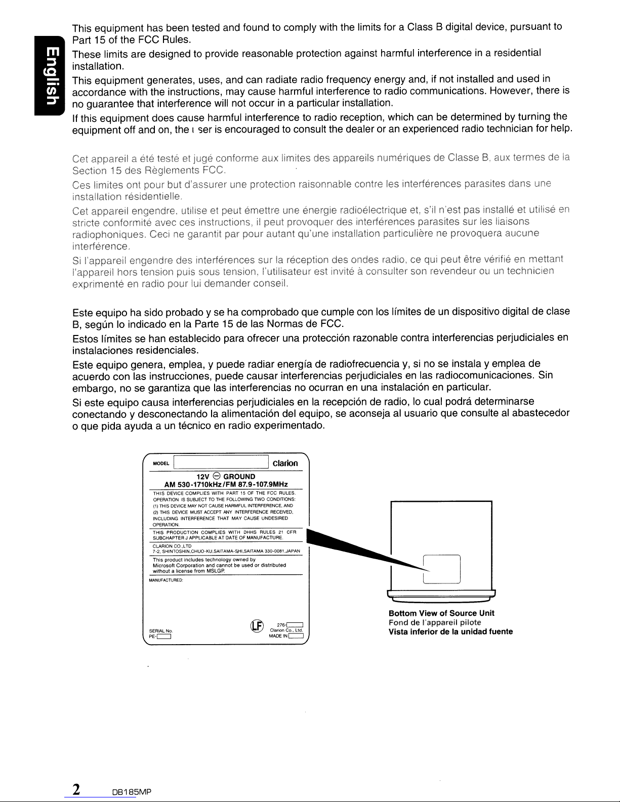
Bottom ViewofSource Unit
Fond de I'appareil pilote
Vista inferior de la unidad fuente
Page 3
CLARION PRODUCT REGISTRATION INFORMATION
For
USA and
www.clarion.com
Dear Customer:
Congratulations on your purchase of a Clarion mobile electronic products. We are confident
YOU'll
that
There are many benefits to registering your product.
www.clarion.com
We have made product registration simple with our easy to use website. The registration form
is short and easy to complete. Once you're registered, we can keep you informed of important
product information.
Register at
Thank you for purchasing this Clarion product.
* Please read this owner's manual
* After reading this manual, be sure to keep it
enjoy your Clarion experience.
to register your Clarion product.
www.clarion.com
- it's easy to keep your Clarion product up to date.
in
its entirety before operating this equipment.
in
Canada
We
a handy place (e.g., glove compartment).
only
invite you to visit our website at
* Check the contents of the enclosed warranty card and keep it carefully with this manual.
Contents
1.
FEATURES ; 4
2.
PRECAUTIONS 4
Handling Compact Discs 5
3.
CONTROLS 6
Names of the Buttons and Their Functions 6
Display Items 8
Display Screen 8
4.
DCP
(DETACHABLE CONTROL PANEL) 9
5.
REMOTE CONTROL 10
Functions of Remote Control Unit Buttons 10
Inserting the Battery 12
6.
OPERATIONS
Basic Operations 13
Radio Operations 16
CD/MP3IWMA Operations 18
Operations Common to Each Mode 22
7.
TROUBLESHOOTING
8.
ERROR
9.
SPECIFICATIONS
DISPLAYS
13
24
25
26
DB1B5MP 3
Page 4

1. FEATURES
illJDO~trJ
DIGITALA 010
EXT
• High Visibility Single Line Display
• 4ch/2V RCA Output
• Front Panel 3.5mm Auxiliary Input
1R?3
ID3TAG
2. PRECAUTIONS
1.
When the inside of the car is very cold and
the player is used soon after switching
heater moisture may form on the disc or the
optical parts of the player and proper
playback may not be possible. If moisture
forms on the disc, wipe
If
moisture forms on the optical parts of the
player, do not use the player for about one
hour. The condensation will disappear
naturally allowing normal operation.
2.
Driving on extremely bumpy roads which
cause severe vibration may cause the sound
to skip.
3.
This unit uses a precision mechanism. Even
in
the event that trouble arises, never open
the case, disassemble the unit,
the rotating parts.
it
off with a soft cloth.
or
on
lubricate
the
••
--,PlaYS'----i
'-'
Windows
•
_TM
USE OF CONTROLS, ADJUSTMENTS,
PERFORMANCE OF PROCEDURES OTHER
THAN THOSE SPECIFIED HEREIN, MAY
RESULT
EXPOSURE.
THE COMPACT DISC PLAYER SHOULD NOT
BE ADJUSTED OR REPAIRED BY ANYONE
EXCEPT PROPERLY QUALIFIED SERVICE
PERSONNEL.
CHANGES OR MODIFICATIONS NOT
EXPRESSLY APPROVED BY THE
MANUFACTURER FOR COMPLIANCE
COULD VOID THE USER'S AUTHORITY TO
OPERATE THE EQUIPMENT.
INFORMATION FOR USERS:
CHANGES OR MODIFICATIONS TO THIS
PRODUCT
MANUFACTURER WILL VOID THE
WARRANTY AND WILL VIOLATE FCC
APPROVAL.
IN
HAZARDOUS RADIATION
NOT
APPROVEDBYTHE
Media
TV
OR
4 DB185MP
Page 5

Handling Compact Discs
Use only compact discs bearing the
mJO§@
mark.
~
Do not play heart-shaped, octagonal, or other
specially shaped compact discs.
Some CDs recorded in CD-R/CD-RW mode
may not be usable.
mJO§@
DIGITAL
AUDIO
or
Handling
• Compared to ordinary music CDs, CD-R and
CD-RW discs are both easily affected by high
temperature and humidity and some of CD-R
and CD-RW discs may not be played.
Therefore, do not leave them for a long time
in
the car.
• New discs may
have some
roughness
around the
edges. If such
discs are used,
the player may
not work or the
sound may
skip. Use a ball-point pen
remove any roughness from the edge of the
disc.
• Never stick labels on the surface of the
compact discor mark the surface with a
pencil or pen.
• Never
cellophane tape or other glue on it
peeling off marks. If you try to play such a
compact disc, you may not be able to get it
back out of the CD player or it may damage
the CD player.
• Do not use compact discs that have large
scratches, are misshapen, cracked, etc. Use
of such discs may cause misoperation or
damage.
• To remove a compact disc from its storage
case, press down on the center of the case
and lift the disc out, holding it carefully by the
edges.
• Do not use commercially available CD
protection sheets or discs equipped with
stabilizers, etc. These may damage the disc
or cause breakdown of the internal
mechanism.
playa
Ball-point pen
or
the like to
compact disc with any
or
with
Storage
•
Do
not expose compact discs to direct
sunlight or any heat source.
•
Do
not expose compact discs to excess
humidity or dust.
• Do not expose compact discs to direct heat
from heaters.
Cleaning
• To remove fingermarks and dust, use a soft
in
cloth and wipe
center of the compact disc to the
circumference.
• Do not use any solvents, such as
commercially available cleaners, anti-static
spray, or thinner to clean compact discs.
• After using special compact disc cleaner, let
the compact disc dry off well before playing it.
a straight line from the
OB185MP 5
Page 6
3. CONTROLS
Names
[RELEASE]
[~]
(EJECT)
of
[DISP]---
-h~55~
the Buttons
..
\ /
and
~4=t,lf\=Hi~\~REhttps://manualmachine.com/~=
-.
[!+II),
[~]
-+---++f.:~~1-
[ISR]---'
[ROTARY]
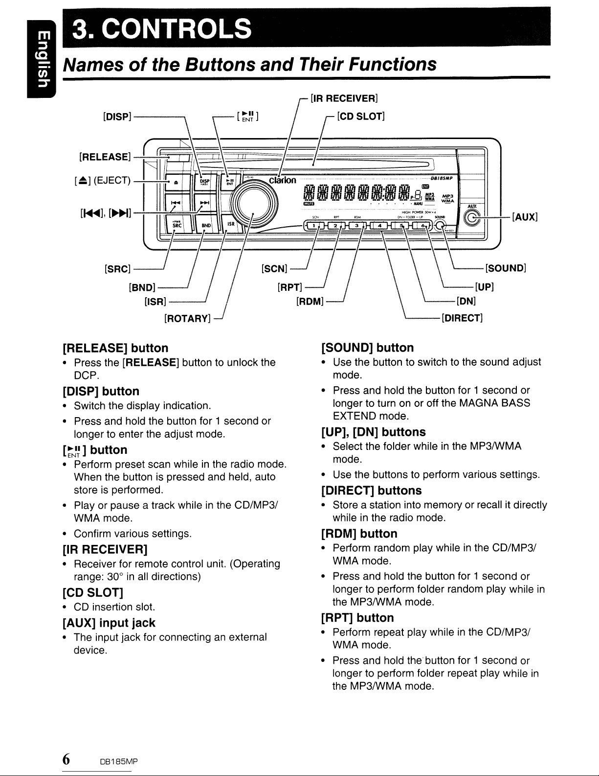
[RELEASE]
• Press the [RELEASE] button to unlock the
OCP.
[DISP]
• Switch the display indication.
• Press and hold the button for 1 second or
longer to enter the adjust mode.
[~~~]
button
• Perform preset scan whileinthe radio mode.
When the button
store
is
• Play or pause a track while
WMA mode.
• Confirm various settings.
button
button
performed.
is
pressed and held, auto
:::;:::\Il~
[SCN]
in
the
CD/MP31
[IR RECEIVER]
• Receiver for remote control unit. (Operating
range: 30°
in
all directions)
[CD SLOT]
• CD insertion slot.
[AUX]
• The input jack for connectinganexternal
device.
input
jack
Their Functions
[IR RECEIVER]
~
[CD SLOT]
~_~
~~
=~~;;;;;
__
;;;;;_;;;;;
;;;;;_~
[RPT]
[ROM]
[SOUND]
• Use the button to switch to the sound adjust
mode.
• Press and hold the button for 1 second or
longer to turn on or off the MAGNA BASS
EXTEND mode.
[UP], [ON]
• Select the folder whileinthe MP3IWMA
mode.
• Use the buttons to perform various settings.
[DIRECT]
• Store a station into memory or recall it directly
while in the radio mode.
[ROM]
• Perform random play whileinthe CO/MP31
WMA mode.
• Press and hold the button for 1 second or
longer to perform folder random play while
the MP3IWMA mode.
[RPT]
• Perform repeat play whileinthe CO/MP31
WMA mode.
• Press and hold the button for 1 second or
longer to perform folder repeat play while
the MP3IWMA mode.
button
buttons
buttons
button
button
:J
\
__::::_~__
~_--IlII~'6:':":5":':'"P-l--~
~-:--[AUX]
'---[SOUND]
'---[UP]
'----[ON]
'---
[DIRECT]
in
in
6 OB185MP
Page 7

Names
of
the Buttons and Their Functions
[SCN] button
• Perform scan play for 10 seconds of each
in
track while
• Press and hold the button for 1 second or
longer to perform folder scan play while
MP3IWMA mode.
the CD/MP3IWMA mode.
in
[ROTARY] knob
• Adjust the volume by turning the knob
clockwise or counterclockwise.
[ISR] button
• RecalllSR radio stationinmemory.
• Press and hold the button for 2 seconds or
longer: Store current station into ISR memory
(radio mode only).
[BND] button
• Switch the band, or seek tuning or manual
in
tuning while
the radio mode.
the
[SRC] button
• Press the button to turn on the power.
• Press and hold the button for 1 second or
longer to turn off the power.
• Switch the operation mode among the radio
mode, etc.
[
.......
],
[~]
• Select a station whileinthe radio mode or
select a track while
mode.
This button
• Press and hold the button for 1 second or
longer to enter the fast-forward or fastbackward mode.
[~]
(EJECT) button
• Eject a disc when it is loaded into the unit.
buttons
in
the CD/MP3IWMA
is
used to make various settings.
DB185MP 7
Page 8
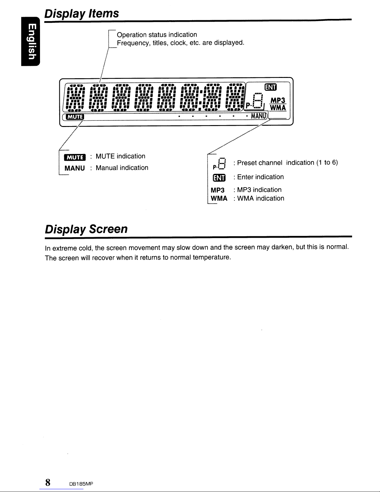
Display Items
MUTE indication
MANU
Manual indication
Operation status indication
Frequency, titles, clock, etc. are displayed.
CI
p·L!
llID
MP3 : MP3 indication
WMA : WMA indication
:Preset channel indication
:Enter indication
(1to6)
Display Screen
In
extreme cold, the screen movement may slow down and the screen may darken, but this is normal.
The screen will recover when it returns to normal temperature.
8 DB185MP
Page 9
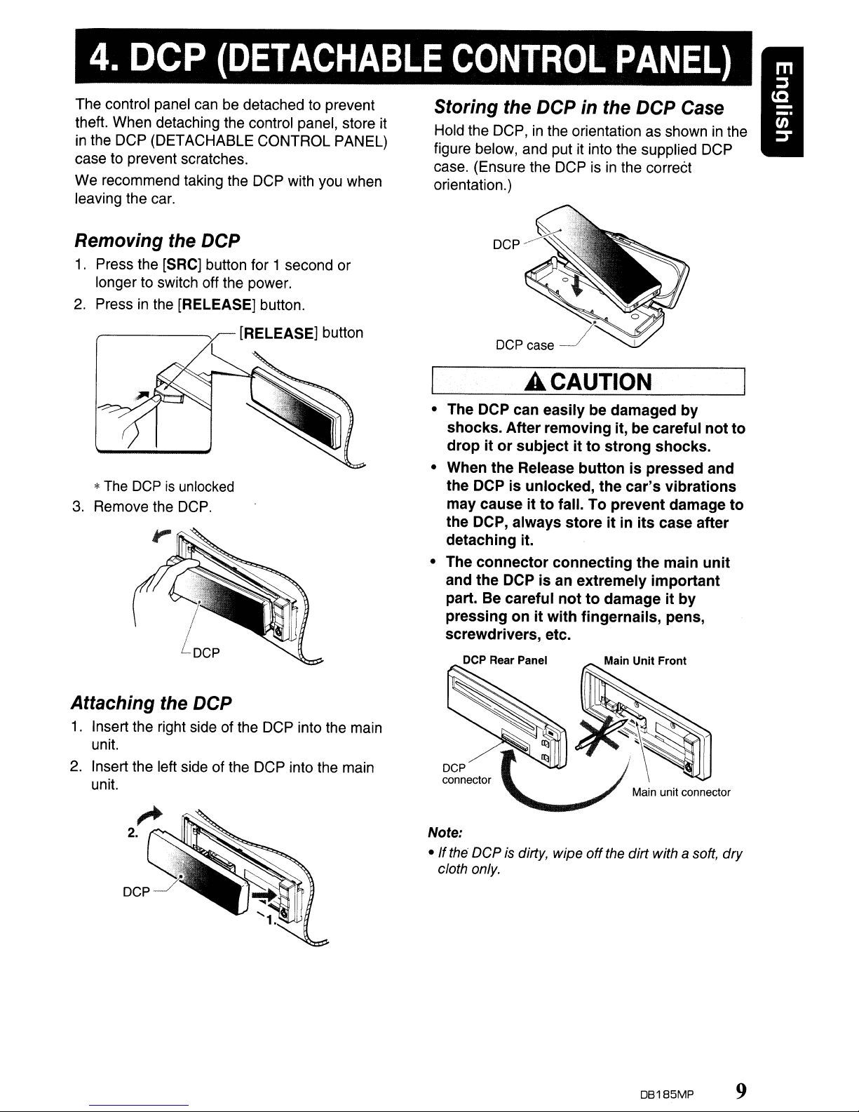
4. DCP
(DETACHABLE
CONTROL
PANEL)
The control panel canbedetached to prevent
theft. When detaching the control panel, store it
in
the DCP (DETACHABLE CONTROL PANEL)
case to prevent scratches.
We recommend taking the DCP with you when
leaving the
car.
Removing the DCP
1.
Press the [SRC] button for 1 second or
longer
2. Press
*
3.
Remove the
to
switch off the power.
in
the [RELEASE] button.
The
DCPisunlocked
[RELEASE] button
DCP.
Storing the DCP in the DCP Case
Hold the DCP,inthe orientation as showninthe
figure below, and put it into the supplied DCP
case. (Ensure the DCP
orientation.)
isinthe correCt
A CAUTION
• The DCP can easily be damaged
shocks.
dropitor
• When
the DCP
may causeitto
the DCP, always
detaching it.
• The
and
part. Be careful
pressingonit
screwdrivers, etc.
After
removing
subjectitto
the
Release
is
unlocked,
connector
the
DCP is an extremely
buttonispressed and
fall.
storeitin
connecting
nottodamageitby
with
it, be careful
strong
the
car's
To
prevent
its
the
fingernails, pens,
by
not
shocks.
vibrations
damage
case after
main
unit
important
to
to
Attaching the DCP
1.
Insert the right side of the
unit.
2.
Insert the left side of the DCP into the main
unit.
DCP
into the main
DCP Rear Panel
DCP
connector
Note:
• Ifthe DCP is dirty, wipe
cloth only.
off
the dirt with a soft, dry
DB185MP 9
Page 10
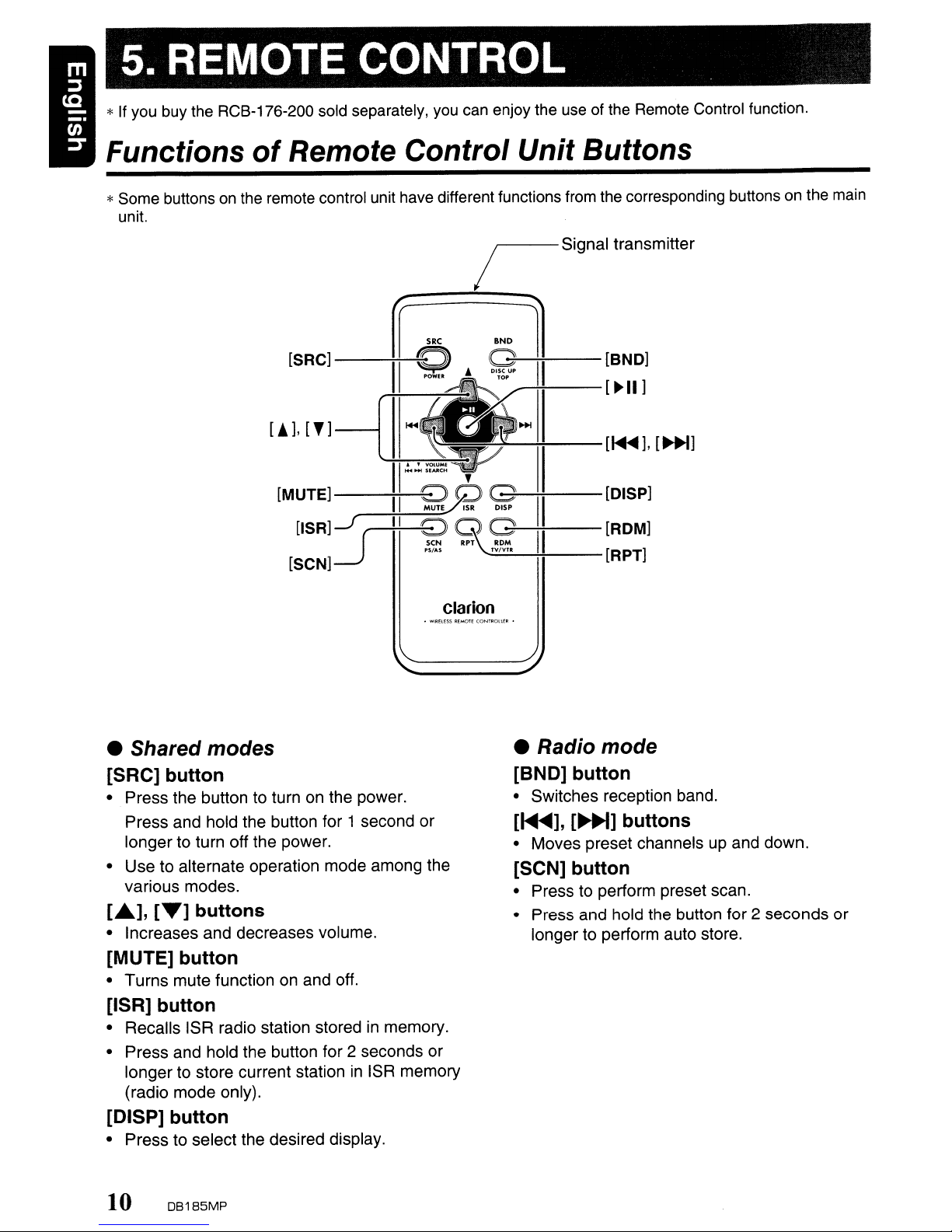
5. REMOTE CONTROL
*If you buy the RCB-176-200 sold separately,
Functions
*Some buttons
unit.
of
Remote Control Unit Buttons
on
the remote control unit have different functions from the corresponding buttons on the main
[SRC]
_---+~:~=O=C~::::::::=G=D
1I~er-I~II]
[AJ,
[,]
[MUTE]---++II_':'':'~
[ISR]~J~\~;..........;.::---
[SCN]
li
you
can
enjoy the
iSignal
::::1
--+:~-[~J,
6 G
~QlSR
seN
"'AS
~
RPT ROM
TV''''
II
II
II
useofthe Remote Control function.
transmitter
[BND]
[~]
[DISP]
[ROM]
[RPT]
• Shared modes
[SRC]
• Press the button to turn on the power.
• Use to alternate operation mode among the
[£.],
• Increases and decreases volume.
[MUTE]
• Turns mute function on and off.
[ISR]
• Recalls ISR radio station stored in memory.
• Press and hold the button for 2 seconds or
[DISP]
• Press to select the desired display.
button
Press and hold the button for 1 second or
longer to turn off the power.
various modes.
[T]
buttons
button
button
longer to store current station
(radio mode only).
button
in
ISR memory
Clarion
• Radio mode
[BND] button
• Switches reception band.
[~],
• Moves preset channels up and down.
[SeN]
• Press to perform preset scan.
• Press and hold the button for 2 seconds or
[~]
button
longer to perform auto store.
buttons
10 DB1B5MP
Page 11

Functions
of
Remote Control Unit Buttons
• CDIMP31WMA modes
[BND] button
• Press to play the first track.
[1<llII
....
],
[~~]
• Press to move the tracks up and down.
• Press and hold the button for 1 second or
longer to perform fast-forward/fast-backward.
[~II]
button
• Switches between playback and pause.
buttons
[SeN] button
• Press to perform scan play.
in
• When
button for 1 second or longer to perform folder
scan play.
MP3IWMA mode, press and hold the
[RPT] button
• Press to perform repeat play.
• When in MP3IWMA mode, press and hold the
button for 1 second or longerto perform folder
repeat play.
[ROM] button
• Press to perform random play.
• When
button for 1 second or longerto perform folder
random play.
in
MP3IWMA mode, press and hold the
DB185MP
11
Page 12

Inserting the Battery
CD
Turn over the remote control unit and slide
the cover in the direction indicated by the
arrow in the illustration.
® Insert the battery (CR2025) into the insertion
guides, with the printed side (+) facing
upwards.
® Press the battery in the direction indicated by
the arrow so that it slides into the
compartment.
@ Replace the cover and slide in until it clicks
into place.
Notes:
Misuse may result in ruptureofthe battery,
of
producing leakage
personal injuryordamage to surrounding
materials. Always follow these safety precautions:
• Use only the designated battery.
When
•
• Do not subject battery
• Dispose
replacing the battery, insert properly, with
+/-
polarities oriented correctly.
fire or water.
battery.
Do
of
used batteries properly.
fluid and resulting
to
heat,ordisposeofin
not attempttodisassemble the
in
Insertion guide
12
OB185MP
Page 13

6. OPERATIONS
Note:
• Be suretoread this chapter referringtothe front diagramsofchapter "3. CONTROLS" on page
Basic Operations
6.
A CAUTION
Be suretolower the volume before
off
sWitching
key. The
setting. If you switch the power
volume up, when you switch the power back
on, the sudden loud volume may
hearing and damage the unit.
Turning
Note:
• Be careful about using this unit for a long time
without running the engine.
battery too
engine
battery.
1.
Press the [SRC] button.
2.
Press and hold the [SRC] button for 1
second or longer to turn off the power for the
unit.
the unit powerorthe ignition
unit
remembers
on/off
far,
and
this can reduce the service lifeofthe
the
you may not be abletostart the
its
last volume
off
power
If
you drain the car's
hurt
with the
your
Adjusting the volume
1.
Turning the [ROTARY] knob clockwise
increases the volume; turning it
counterclockwise decreases the volume.
*The volume level is from 0 (minimum) to 33
(maximum).
Switching the display
Press the [DISP] button to select the desired
display.
*If the button operation is performed with the
screen saver function on, the operation display
corresponding to the button operation is shown
for about 30 seconds and the display returns to
the screen saver display.
For details, refer to the subsection "Turning the
on
screen saver function
"Operations Common to
or off'
Each
in
section
Mode".
Selecting a mode
1.
Press the [SRC] button to change the
operation mode.
2.
Each time you press the [SRC] button, the
operation mode changes
order:
Radio'"
CO/MP3IWMA
in
the following
...
AUX
...
Radio...
DB185MP
13
Page 14

Basic Operations
Sound Adjustment
You can adjust a sound effect or tone quality to
your preference.
To
change sound setting
1.
Press the [SOUND] button to switch to the
sound adjustment selection display.
*The factory default
EHCR+".
2.
Then press the
select the sound adjustment mode.
Each time you press the
button, the sound adjustment mode
changes as following order:
"Z-EHCR+"
"BALANCE"
*
In
the caseofdisplay blinking
can
press the
<---+
<---+
setting value.
*The sound adjustment
displayed for 2 seconds before showing
sound setting.
3.
Turn the [ROTARY] knob to adjust the
selected audio mode.
4.
After completing settings, press the
[SOUND] button to return to the previous
mode.
• Setting the Z-Enhancer Plus
This unitisprovided with 4 types of sound tone
effects stored
Select the one you prefer.
*
The
factory default setting
2-1. Select "Z-EHCR+".
3-1. Each time you turn the [ROTARY] knob,
the tone effect changes
order:
"OFF"
"EXCITE"
OFF : no sound effect
B-BOOST
IMPACT
EXCITE : bass and treble emphasized
CUSTOM : user custom
in
memory.
~
"B-BOOST'
<---+
: bass emphasized
: bass and treble emphasized
mid emphasized
sound
[~]or[~]
"BASS"
settingis"Z-
button to
[~]or[~]
<---+
"TREBLE"
"FADER"~"NF VOL"
"ENT",
[~~~]
buttontoadjust the
mode
will
be
is
"OFF".
in
the
follOWing
<---+
"IMPACT'
"CUSTOM"
<---+
you
the
<---+
When
3-2. Press the
"B-BOOST/IMPACT/EXCITE"isset:
[~NI~]
button.
3-3. Turn the [ROTARY] knob to adjust the
setting
*
3-4. Press the
in
the range of-3to +3.
The
factory default settingis"0".
[~~~]
button to return to the
previous mode.
When
3-2. Press and hold the
"CUSTOM"isset:
[~~~
] button for 1
second or longer. Bass/treble
characteristics become flat and "FLAT" is
show
in
the display.
3-3. Turn the [ROTARY] knob to change to the
"OFF" mode.
•
Adjusting
the bass
This adjustment can be performed only when
the Z-Enhancer Plus is set to "CUSTOM
".
2-1. Select "BASS".
3-1. Press the
3-2. Press the [
[~~n
button.
....~]or
[~]
button to select as
following order.
"B<G 0>"
<---+
"B<F 60>"
<---+
"Q
1"
3-3. Turn the [ROTARY] knob to adjust the
gain, the F (center frequency) and the
B<G 0> :The factory default settingis"0".
(Adjustment range:
+7to-7)
B<F 60> :The factory default setting
"60".
(Adjustment range: 60/80/100/
200)
Q 1 :The factory default setting
(Adjustment range: 1/1.25/1.5/2)
3-4. Press the
[~NI~
] button to return to the
previous mode.
Q.
is
is
"1".
14
DB185MP
Page 15

Basic Operations
• Adjusting the treble
This adjustment can be performed only when
the Z-Enhancer Plus is set to "CUSTOM
2-1. Select "TREBLE".
3-1. Press the
3-2. Press the
following order.
"T<G 0>"+4"T<F10k>"
3-3. Turn the [ROTARY] knob to adjust the
gain, the F (center frequency) and the
T<G 0> : The factory default setting is "0".
T<F10k>:
3-4. Press the
previous mode.
[~Jn
button.
[~~]or[~]
(Adjustment range: +7 to
The factory default setting is
"10k".
(Adjustment range: 10k/12.5k/
15k/17.5k)
[~J~]
button to return to the
button to select as
".
Q.
-7)
• Adjusting the balance
2-1. Select
3-1. Turn the [ROTARY] knob to adjust the
balanceofthe right and left speakers.
"BALANCE".
*The factory default setting is "CENTER"
(center). (Adjustment range: RIGHT12 to
LEFT12 (right 12 to left 12))
Setting the MAGNA BASS EXTEND
The
MAGNA
the low frequencies like the normal sound
adjustment function, but emphasizes the deep
bass frequencies to provide you with a dynamic
sound.
*The factory default setting
1.
Press and hold the [SOUND] button for 1
secondorlonger to turn on the
BASS EXTEND effect.
the display for 2 seconds.
2. Press and hold the [SOUND] button for 1
second or longer to turn off the
BASS EXTEND effect. "M-B OFF" appears
in
the display for 2 seconds.
BASS EXTEND does not adjust
is
"OFF" (off).
MAGNA
"M-B
EX" appears in
MAGNA
• Adjusting the fader
2-1. Select "FADER".
3-1. Turn the [ROTARY] knob to adjust the
balanceofthe rear and front speakers.
*The factory default setting
(center). (Adjustment range: FRONT12
REAR12 (front12to rear 12))
is
"CENTER"
to
• Adjusting the non fader output
volume
You can adjust the volume output from the unit's
non fader output terminal.
2-1. Select "NF VOL".
3-1. Turning the [ROTARY] knob clockwise
increases the output volume; turning it
counterclockwise decreases the output
volume.
*The factory default setting
(Adjustment range:-6to +6)
Note:
• During SOUND adjustment mode,ifno
operation is performed for more than
seconds, this mode canbecancelled
to
previous mode.
is
"0".
10
and
return
DB185MP
15
Page 16

Radio Operations
Listening to the radio
1.
Press the [SRC] button and select the radio
mode. The frequency appears
2.
Press the [BND] button and select the radio
band. Each time the button is pressed, the
radio reception band changes
following order:
F1
(FM1)~F2 (FM2)~F3 (FM3)~AM
F1
(FM1)...
3.
Pressthe[~]or[~]buttontotuneinthe
desired station.
in
the display.
in
the
~
Tuning
There are 3 types of tuning mode available,
seek tuning, manual tuning and preset tuning.
Seek
1.
2.
Manual
There are 2 ways available: Quick tuning and
step tuning.
When you are in the step tuning mode, the
frequency changes one step at a time.
quick tuning mode, you can quickly tune the
desired frequency.
1.
2.
tuning
Press the [BND] button and select the
desired band (FM or AM).
*
If
"MANU"islitinthe
the
[BND] button for 1 second or longer.
"MANU"
tuningisnow available.
Press the
automatically seek a station.
When the
is
sought in the direction of higher
frequencies; if the
the station is sought in the direction of lower
frequencies.
in
the
[~]or[~]
[~]
display, press
display goes off
button to
button is pressed, the station
[~]
button is pressed,
and
and
seek
hold
tuning
In
the
Press the [BND] button and select the
desired band (FM or AM).
*
If
"MANU"isnot litinthe
hold the [BND] button for 1
"MANU"
is
Tune into a station.
now
is
litinthe display
available.
display, press
secondorlonger.
and
manual
and
tuning
• Quick
Press and hold the
second or longer to tune in a station.
• Step
Press the
in
a station.
tuning
tuning
[~]or[~]
[~]or[~]
button to manuallytune
button for 1
Recalling a preset station
A total of 24 preset positions (6-FM1 , 6-FM2, 6FM3, 6-AM) exists to store individual radio
stations
[DIRECT] button to recall the stored radio
frequency automatically.
1.
2.
in
memory. Press the corresponding
Press the [BND] button and select the
desired band (FM or AM).
Press the corresponding [DIRECT] button to
recall the stored station.
Note:
• Press
and
seconds
memory.
hold
oneofthe [DIRECT] buttons for 2
or
longertostore thatstation into preset
Manual memory
1.
Select the desired station with seek tuning or
manual tuning.
2.
Press and hold one of the [DIRECT] buttons
for 2 seconds or longer to store the current
station into preset memory.
Auto store
Auto store is a function for storingupto 6
stations that are automatically tuned
sequentially. If 6 receivable stations cannot
received, a previously stored station remains
unoverwritten at the memory position.
1.
Press the [BND] button and select the
desired band (FM or AM).
2.
Press and hold the
or longer. The stations with good reception
are stored automatically to the preset
channels.
[~NI:]
button for 2 seconds
in
be
16
DB185MP
Page 17

Radio Operations
Preset scan
Preset scan receives the stations stored
preset memoryinorder. This functionisuseful
when searching for a desired station
1.
Press the
2.
When a desired stationistuned in, press the
[~J~]
station.
Note:
• Be careful nottopress
for
2 seconds
function is engaged and the unit starts storing
stations.
[~J~]
button.
button again to continue receiving that
and
hold the
or
longer, otherwise the auto store
in
in
memory.
[~NI~
Jbutton
Instant station recall (/SR)
Instant station recallisa special radio preset
that instantly accesses a favorite radio station at
a touch of a button. The ISR function even
operates with the unit
elSR
1.
2.
• Recalling a
In
the radio function and tune the selected radio
station. "ISR" appears in the display. Press the
[ISR] button again to return to the previous
mode.
memory
Select the station that you wish to store
ISR memory.
Press and hold the [ISR] button for 2
seconds or longer.
station
any mode, press the [ISR] button to turn
in
other modes.
with
ISR
in
on
D8185MP
17
Page 18

CDIMP31WMA Operations
MP3/WMA
What is MP3?
MP3 is an audio compression method and
classified into audio layer3 of MPEG standards.
This audio compression method has penetrated
into PC users and become a standard format.
This MP3 features the original audio data
compression to about 10 percent of its initial
size with a high sound quality. This means that
about 10 music CDs can be recorded on a CD-R
disc or CD-RW disc to allow a long listening time
without having to change CDs.
What is
WMA
Audio,
Microsoft Corporation.
Notes:
• If you
Management) for
is
output (The WMA indicator blinks).
• Windows Media
trademarks,
Microsoft Corporationinthe United States and/or
other countries.
•
To
Management)
1.
When using Windows Media Player 9/10/11,
click
RECORD tab, then under Recording
settings, unclick the Check box for RECORD
PROTECTED MUSIC. Then, reconstruct
files.
Personally constructed WMA files are used
at your own responsibility.
WMA?
is the abbreviation of Windows Media
an
audio file format developed by
playa
disable
file with DRM (Digital Rights
WMA
remaining
TM,
and the Windows ® logo are
or
registered trademarks
DRM (Digital
on
TOOL~OPTIONS~MUSIC
Rights
ON,
no audio
of
Precautions when creating
WMA
•
1.
2.
•
1.
2.
•
1.
2.
3.
•
1.
2.
3.
file
Usable
MP3: Sampling rate 8 kHz-48 kHz,
Bit rate: 8 kbps-320 kbps / VBR
WMA: Bit rate 48 kbps-192 kbps
File
Always add a file extension ".MP3" or
".WMA" to MP3 or WMA file by using single
byte letters. If you add a file extension other
than specified or forget to add the file
extension, the file cannot be played.
Files without MP3IWMA data will not play.
The indication
time display if you attempt to play files
without MP3IWMA data.
Logical
When writing MP3IWMA file on a CD-R disc
or CD-RW disc, please select
1,2
software format. Normal play may not be
possible if the disc is recorded on another
format.
The folder name and file name can be
displayed as the title during MP3IWMA play
but the title must be within 64 single byte
alphabetical letters and numerals (including
an extension).
Do not affix a name to a file inside a folder
having the same name.
Numberoffilesorfolders
Up to 256 files can be recognized per folder.
Up to 578 files can be played.
Tracks are playedinthe order that they were
recorded onto a disc. (Tracks might not
always be played
the PC.)
Some noise may occur depending on the
type of encoder software used while
recording.
sampling
extensions
format
or JOLIET or Romeo" as the writing
rates
and
"-
-:-
-"
appearsinthe
(File
system)
in
the order displayed on
MP31
bit
rates
"IS09660
play
level
18
DB185MP
Page 19

CDIMP31WMA
Operations
Disc-In-Play function
As long as the ignition key is turned to the ON or
ACC position, this function allows you to turn the
power to the unit and start playing the disc
automatically when the disc is inserted even if
the power is not turned on.
A CAUTION
•
Do
nottry to
the disc insertion slot. Also never insert
foreign objects
Do
not insert
•
out from cellophane tape
label,ordiscs with marks where
cellophane tape
removed. It may be impossible to extract
these discs from the
cause the unit to break down.
Ejecting a
1.
Press the
from the ejected position.
in
the display.
Notes:
• If a CD (12 cm)
15
seconds, the CDisautomatically reloaded.
(Auto reload)
• If you force a CD into before auto reloading, this
can damage the
Listening
unit
the
Press the
WMA mode.
When the unit enters the CD/MP3IWMA mode,
play starts automatically.
If there is no disc loaded, the indication
DISC"
The mode changes each time the
is pressed.
Radio~CD/MP3IWMA~AUX~Radio
[SRC]
appearsinthe display.
put
your
handorfingers in
into
the slot.
discs
where adhesive comes
or
a rental
or
rental
CD
unit
and they may
labels were
CD
[~]
to eject the CD. Take it out
"EJECT" appears
is
left in the ejectedposition for
CD.
to
a disc already loaded in
button to select the
CD/MP31
[SRC] button
CD
"NO
...
Loading a
1.
Insert a CD into the centre of the CD SLOT
with the labeled side facing up.
appearsinthe display, the CD enters into the
slot, and the play starts.
Notes:
• Never insert foreign objects into the CD
• Ifthe CD
another CD in the mechanism or the unit may
require service.
• Discs not bearing the
CD-ROMs cannotbeplayedby[fiiSijnit.
• Some CDs recorded in CD-RICD-RW mode may
not be usable.
CD
"LOADING"
is
notinserted easily, there may be
ffij'o.""
~i~or~
SLOT.
mark
and
Pausing play
1.
Press the
"PAUSE" appears
2.
To resume CD play, press the
again.
Displaying
This unit can display title data for CD-textlMP31
WMA disc and user titles input with this unit.
1.
Each time you press the [DISP] button to
change the title display.
• CD-TEXT
Track~Disc~Artist~Track
• MP3IWMA
Track~Folder~Title~Album~Artist
Track
Notes:
• If the CD playing
·If
• For MP3, supports 103 Tags
•
•
• IS08859-1, ASCII, S-JIS characters can be
• Titles
...
title has been input, "NO TITLE" appears in the
display.
MP31WMA discisnot input
appears
Tag
displays give prioritytoV2.3
In
the caseofalbum Tags for
information written into the extension header
displayed.
displayed
UNKNOW characters can be turned
1characters.
up
MP31WMA mode.
[rNI~
] button to pause play.
in
the display.
[r~~]
button
CD
titles
disc
...
disc
~
is
nota CD-text CDorno user
TAG,
"NO TITLE"
in
the display.
V2.3
I 2.2 11.1 I
I 2.2.
WMA,
the
in
Tags.
to
IS08859-
to32bytes can be displayed in COl
1.0.
is
DB1B5MP 19
Page 20

CDIMP31WMA
Operations
Selecting
a track
• Track-up
1.
Press the
beginning of the next track.
2.
Each time you press the
track advances ahead to the beginning of the
next track.
[~]
button to move ahead to the
[~]
button, the
• Track-down
1.
Press the
beginning of the current track.
2.
Press the
the beginning of the previous track.
[~]
button to move back to the
[~]
button twice to move back to
Fast-forwardlfast-backward
• Fast-forward
1.
Press and hold the
or
longer.
[~]
button for 1 second
• Fast-backward
1.
Press and hold the
or
longer.
*For MP3IWMA discs,
start of searching and between tracks.
the playing time may have a margin of error.
[~]
button for 1 second
it
takes some time until the
In
addition,
Folder Select
This function allows you to select a folder
containing MP3IWMA files and start playing
from the first track in the folder.
1.
Press the [UP] or [ON] button.
Press the [UP] button to move the next
folder. Press the [ON] button to move the
previous folder.
2.
To select a track, press the
button.
[~]or[~]
Other various play functions
• Scan play
This function allows you to locate and play the
first 10 seconds of all the tracks recorded
disc.
1.
Press the [SCN] button to perform scan play.
''TRK SCN" appears
seconds.
*Scan play starts
track currently being played.
in
the display
from
the next track after the
• Folder scan play
This function allows you to locate and play the
first 10 seconds of the first track of all the folders
on an MP3IWMA disc.
1.
Press and hold the [SCN] button for 1
second
"ALL
seconds.
*Folder
or
longer to perform folder scan play.
SCN" appearsinthe display for 2
scan
play starts
after the folder currently being played.
from
the next folder
• Repeat play
This function allows you to play the current track
repeatedly.
1.
Press the [RPT] button to perform repeat
play.
''TRK
RPr'
appearsinthe display for 2
seconds.
for
on
a
2
20
DB185MP
Page 21

CDIMP31WMA
Operations
• Folder repeat play
This function allows you to
being played in the MP3IWMA folder
repeatedly.
1. Press and hold the
or longer to perform folder repeat play.
"ALL
RPT"
appearsinthe display for 2
seconds.
playa
[RPT]
track currently
button for 1 second
• Random play
This function allows you to play all tracks
in
recorded on a disc
1. Press the
play.
"TRK
seconds.
[ROM]
ROM"
a random order.
button to perform random
appearsinthe display for 2
• Folder random play
This function allows you to play all the tracks of
all the folders recorded on an MP3IWMA disc in
a random order.
1.
Press and hold the
second
play.
"ALL
seconds.
.To
1.
Press the operating button previously
selected.
or
longer to perform folder random
ROM"
appearsinthe display for 2
cancel play
*The various play mode
various playoff mode appears
seconds.
*When
the
error display indication"--:appearsinthe display, the various play (Scan/
Repeat/Random) functions can
play mode.
[ROM]
is
canceled
button for 1
and
the
in
the display for 2
-"
be
canceled
in
D8185MP
21
Page 22

Operations Common to Each Mode
To change adjustment setting
1.
Press and hold the [DISP] button for 1
second or longer to switch to the
adjustment selection display.
2.
Press the [....~lor
"item
the
"CLOCK"~"SETTINGS"~"SCRN SVR"
~
"SCROLL"~"DIMMER"~"TEL-SP"
~
"TEL-SW"
name".
*The adjustment item name will
for 2 seconds before showing the desired
value.
3.
Turn the [ROTARY] knob to select the
"desired
*
In
can
setting value.
setting
the caseofdisplay blinking"ENT",you
press the
[~Hl
button to select
value".
[~NI~
j buttontoadjust the
be
displayed
*After completing settings, press the [DISPj
button to return to the previous mode.
• Setting the
2-1. Select "CLOCK".
3-1. Press the
3-2. Press the
hour or the minute.
3-3. Turn the [ROTARY] knob to set the correct
time.
*The clock
3-4. Press the
memory and return to the previous mode.
Note:
•
You
cannotsetthe clock when it is displayed
with only the ignition
the car's battery
reset. While setting the clock,ifanotherbutton
operation is selected, the clock setmode is
canceled.
clock
[~~~]
button
[~]or[~]
is
displayedin12-hour format.
[~~~]
button to store the time into
on.
or
take out this unit, the
button to select the
Ifyou drain
or
remove
clock
is
or
• Displaying the settings
The number of indicator of this unit decreases,
you can see the state of current settings at any
operation mode.
2-1. Select "SETTINGS".
3-1. Turn the [ROTARY] knob to display the
state of current settings.
*When the setting
the
current state willbedisplayed.
For example: after 1 second,
P1-IIEg
is
selected, after 1 second
(r1-
or
.....--
(r1-I1
II
t]rJ
------,
[IFF
• Turning the screen saver function on
or
off
This unit is provided with the screen saver
function which allows you to show various kinds
of
patterns and charactersinthe operation
status indication area of the display in a random
order. You can turn on or off this function. If the
button operation is performed with the screen
saver function on, the operation display
corresponding to the button operation is shown
for about 30 seconds and the display returns to
the screen saver display.
*The factory default setting is
2-1. Select "SCRN SVR".
3-1. Turn the [ROTARY] knob to select "ON" or
"OFP'.
"ON".
22
DB185MP
Page 23

Operations Common to Each Mode
• Setting the method
Set how to scroll in CD-TEXT, MP3IWMA title.
*
The
factory default settingis"ON".
2-1. Select "SCROLL".
3-1. Turn the [ROTARY] knob to select "ON" or
"OFF".
• ON:
To scroll automatically.
• OFF:
To scroll just 1 time.
for
title scroll
• Setting the dimmer control
You can set the dimmer control "ON" or "OFF".
*
The
factory default settingis"ON".
2-1. Select "DIMMER".
3-1. Turn the [ROTARY] knob to select "ON" or
"OFF".
• Setting the car speaker output for the
cellular phone
*
The
factory default settingis"RIGHT".
*To output the telephone calls, set the cellular
phone interrupt to
When the AUX input jack is used to connect
AUX BLUETOOTH BB (BLT370) (sold
separately):
2-1. Select "TEL-SP".
3-1. Turn the [ROTARY] knobto select "RIGHT'
or "LEFT".
• RIGHT:
Telephone calls can be heard on the front
right speaker connected to this unit.
• LEFT:
Telephone calls can be heard
left speaker connected to this unit.
"ON".
on
an
the front
• Cellular phone interrupt setting
If you connect this unit and your cellular phone
with a separately sold cable, you can listen to
your telephone calls on your car speakers.
*
The
factory default settingis"OFF".
When the AUX input jack is used to connect an
AUX BLUETOOTH BB (BLT370) (sold
separately):
2-1. Select "TEL-SW".
3-1. Turn the [ROTARY] knob to select the
setting. Each time you turn the [ROTARY]
in
knob, the setting changes
order:
+-+
"ON"
+->
"OFF"
• OFF:
This unit continues normal operation even
when the cellular phone is used.
• ON:
You can listen to your telephone calls from
the speakers connected to this unit.
*
When
listeningtoyour callsonyour car
speakers,
turning the [ROTARY]
• MUTE:
The sound from this unit is muted during
telephone calls.
Note:
• If connecting a hands-free
setting
through the system.
AUX
This system hasanexternal input jack on the
front panel so you can listen to sounds and
music from external devices connected to this
unit.
is
function
you
ONtoreceive the telephone audio
"MUTE"
can
adjust
kit,
the following
the
volume
knob.
please ensure the
by
• Selecting AUXINsensitivity
Make the following settings to select the
sensitivity when sounds from external devices
connected to this unit are difficult to hear even
after adjusting the volume.
*
The
factory default settingis"MID".
1.
Press and hold the [DISP] button for 1
second or longer.
2.
Select "AUX SENS".
3.
Turn the [ROTARY] knob to select "HIGH",
"MID" or "LOW".
Note:
•
When
AUX
modeisselected, AUX IN sensitivity
can be set.
DB185MP
23
Page 24

TROUBLESHOOTING
7.
•.....
Problem
'Cadse,'
'
.....
Power does not
, turn on.
'.
(No sound
..•.
produced.)
No sound output
when operating
the unit with
amplifiers or
power antenna
attached.
l!
I--
co!
Nothing happens The microprocessor has Turn off the power, then press
'I)
" when buttons are malfunctioned due to noise, the [RELEASE] button and
'pressed. etc. remove the DCP.
Display is not 2 seconds with a thin rod.
, accurate.
I,,,;'
'
is
;"::'
.
1--------+------------+--------------------1
No sound heard
Fuseisblown.
Incorrect wiring.
Power antenna lead
shortedtoground or
excessive current
for remote-on the amplifiers
or power antenna.
is
is
required
+-
DCP or main unit connectors
are dirty.
The speaker protection circuit
is operating.
Replace with a fuse of the same amperage,
blows again, consult your store of purchase,
Consult your store of purchase.
1.
Turn the unit off.
2.
Remove
lead. Check each wire for a possible short to
ground using
3.
Turn the unit back on.
4. Reconnect each amplifier remote wire
antenna lead one by one. If the amplifiers turn off
before all wires are attached, use
to provide remote-on voltage (excessive current
+-_r_e_q_u_ir_ed_)_.
Press the reset button for about
Wipe the dirt off with a soft cloth moistened with
cleaning alcohol.
1.
Turn down sound volume. Function can also
restored by turning the power off andonagain.
(Speaker volume is reduced automatically when
the speaker protection circuit operates).
2.
If the sound is muted again, consult our service
department.
all
wires attached to the power antenna
an
ohm meter.
-------------------1
to
an
external relay
~Reset
'"
~~
~
~111'
/'
If the fuse
the power
button
~
.......
~
be
, No sound heard
"
Ie'
Sound skips or
".",' noisy.
~-
'I,,;
Sound is cut or
,G.:
skipped.
J
I'
Noise
'.(J,
, noise is mixed
. with sound.
, Sound is bad
••.
_ directly after
" power is turned
,
",;I-------t----'---------+:-:-,,--:-::---------::---------!
" Wrong filename File systemisnot correct. Use IS09660 level 1,2or JOLIET or Romeo file
.;
is
generated or
on.
MP3IWMA files are absent
a disc.
Files are not recognized as
an MP3IWMA file.
File system is not correct. Use
Compact disc is dirty.
is
Compact disc
scratched or warped.
MP3IWMA files are not
encoded properly.
Water droplets may form
the internal lens when the car
is parkedina humid place.
is
heavily
Write MP3IWMA files onto the disc properly.
in
Use MP3IWMA files encoded properly.
IS09660
system.
Clean the compact disc with a soft cloth.
Replace with a compact disc with no scratches.
Use MP3IWMA files encoded properly.
Let dry for about
on
system.
level 1,2or JOLIET or Romeo file
1 hour with the power on.
24 DB185MP
Page 25

8. ERROR DISPLAYS
If an error occurs, one of the following displays is displayed.
Take the measures described below to eliminate the problem.
Error
Display.
"..CauSe
Measure
. ERROR 2
ACDis
caught inside the
CD
Thisisa failure of
CD
deck's mechanism and consult
< deck and is not ejected. your store of purchase.
:&1-----------1---------+----------------1
~ ERROR 3 A
..
~.'
I'J-E-R-R-O-R-6----+-A-C-D-is-'-0-ad-e-d-u-p-s-id-e--d-o-w-n---+-E-je-c-t-th-e-d-is-c-t-h-e-n-re-I-oa-d-it-p-ro-p-e-rl-y.-------1
B;
If an error display other than the ones described above appears, press the reset button. If the problem
persists, turn off the power and consult your store of purchase.
CD
cannotbeplayed due Replace with a non-scratched, non-warped-disc.
to
scratches, etc.
inside the
not play.
CD
deck and does
DB185MP 25
Page 26

9. SPECIFICATIONS
FM
Tuner
Frequency Range: 87.9 MHz to 107.9 MHz
Usable Sensitivity: 9 dBf
50dB Quieting Sensitivity: 15 dBf
Alternate Channel Selectivity: 70 dB
(1
Stereo Separation
Frequency Response (±3 dB): 30 Hz to 15 kHz
AM Tuner
Frequency Range: 530 kHz to
Usable Sensitivity: 25
CD
Player
System: Compact disc digital audio system
Usable Discs: Compact disc
Frequency Response
Dynamic Range
Harmonic Distortion:
kHz):35dB
IJV
(±1
(1
kHz): 85 dB
0.01
1710kHz
dB): 5 Hz to 20 kHz
%
General
Power Supply Voltage:
14.4 V DC (10.8 to 15.6 V allowable), negative
ground
Current Consumption: Less than 15 A
Speaker Impedance: 4
Weight / Source unit: 2.57 lb. (1.14 kg)
Dimensions / Source unit:
7"
(Width) X2"(Height) X 6-1/8" (Depth)
[178 (W) X 50 (H) X 155 (D) mm]
Power Output :
20WRMS
and 1
SignaltoNoise Ratio:
87
dBA (reference: 1 W into 4 )
x 4 Channels at 4
% THD+N
Q (4 Q to 8 Q allowable)
Audio
Maximum Power Output: 200 W (50 W X 4 ch)
-14
Bass Control Action (100 Hz): +14 dB,
Treble Control Action (10 kHz): +14 dB,
Line Output Level (CD 1 kHz): 1.8 V
Note:
and
• Specifications
design are subjecttochange without notice for further improvement.
dB
-14
dB
26 DB185MP
Page 27

Clarion Co., Ltd.
2007/12
All Rights Reserved. Copyright © 2007: Clarion Co.,
PrintedinChina / impnm€enChine / Impreso en China
Ltd.
PE-30498
280-8589-00
Page 28

PrintedinChina
IlmpruneenCiline/Impre_s_o_en_C_h_in_a
.....;;2..;.OO..;.7..;.1_11'--
..;.2::.8;;.4..;.-....;1..=2-=0=2...;-0""0;.....
---,
-
~
i~~;.....iI
••
,.~~
~~_b
",_I.
1M
InstaliationlWire Connection Guide
Manuel d'installation et de connexion
Guia de instalacion/conexion de cables
.......
-1.
BEFORE STARTING / PREPARATIFS / ANTES DE COMENZAR
1.
This
set
is exclusively for
useincars
with a
negative ground,
12Vpower
supply.
2. Read
these
instructions carefully.
3. Be
suretodisconnect
the
battery "8" terminal
before starting.
This
is to
prevent
short
circuits
during installation. (Figure
1)
1.
Cet
apparell
est
exclusivement
destine
aetre
utilise
dans
les
voitures
avec
une alimentation
12
V a
masse
negative.
2, Lire ces instructions
attentivement
3.
S'assurerdedebrancher
la borne
"E)"
de
la
batterie
avantdecommencer.
Cela eVltera les
court-circuits
pendant
I'installatlon,
(Figure
1)
1.
Esta
unidadhasido
disenada
para
utilizarse
exclusivamenteenautom6viles
con
fuente
de
alimentaci6nde12V,Y
negativo
amasa.
2.
Lea
cuidadosamente
estas
instrucciones.
3.
Antesdecomenzar,
cerci6resededesconec-
tar
el terminal "8"dela
bateria.
Estoespara
evitar
cortocircuitos
durantelainstalaci6n.
(Figura
1)
Figure 1 / Figure 1/ Figura 1
Car
battery
Bauerie de vo!ture
Bateria del autom6vil
.......
-2.
CAUTIONSONINSTALLATION/PRECAUTIONSAUSUJETDEL'INSTALLATION/PRECAUCIONES
PARALAINSTALACION
1.
Prepare
all articles
necessary
for
installing
the
source
unit
before
starting.
2. Install the unit within 30°
of
the
horizontal plane.
(Figure
2)
3.
If
you
havetodo
any
workonthe
car
body,
such
as drilling holes,
consult
your
car
dealer
beforehand.
4.
Use
the
enclosed
screws
for
installation.
Using
other
screws
can
cause
damage.
(Figure 3)
Avant de
commencer.
preparer
Joutes les
pieces
necessaires
pour
installer I'apparel! pilote
2.
Installer I'appareil
avec
un angle inferieur a 30'
par
rapport a
Iho-
rlzontal.
(Figure
2)
3, S'il est
necessaire
d'effectuer
certains
travaux sur la
carrosserie
comme
percer
des
trous.
consulter
d'abord
votre conceSSlonnalre
automobile.
4. Utiliser les vis fournies
pour
I'installation L'utilisation
d'autres
vis
peut
causer
des
dommages,
(Figure 3)
1.
Antesdecomenzar,
prepare
todos
los
elementos
necesarios
para
instalarlaunidad
fuente.
2.
Instale la
unidad
conunangulo
de
30°
sobreelplano
horizontal.
(Figura
2)
3. Si
tiene
que
realizar
cualquier
trabajoenla
carroceria,
como
taladradodeorificios, etc.,
consultealproveedordesu autom6vil.
4.
Use
los
tornillos
incluidos
para
la instalaci6n. EI
usodeotros
tornillos
puede
causar
danos.
(Figura
3)
..,~,u"
,M',~(
-'-----------~
Chassis I Ctlassis I Chasis
ib-
Max. 8mm/8mmmax, I Max, 8 mm
Chassis I Chassis/ Chasis
~_-_-_-
0__'
'""'"'~.,
0000
Figure 2 / Figure 2 / Figura 2
Figure 3 / Figure3/Figura 3
.......
-3.
INSTALLING
THE
SOURCE
UNIT
/ INSTALLATIONDEL'APPAREIL PILOTE / INSTALACIONDELA UNlOAD
FUENTE
• Montage
universel
1. Placer
Ie
supportdemontage
ulliversel
dansIetableaudebord,
utlliser un
tournevis
pour
repiler vers I'exterieur
cheque
languette
du
supportdemontage
universel, puis fixer ies
languettes
cornme
montre
sur la Figure 4.
2 Cabler
comme
montre
dans
la Section 6
3.
Inserer
dans
Ie supportdemontage
universel Jusqu'a
ce
qu
il
• Universal Mount
1.
Place the
universal
mounting
bracket
into
the
instrument
panel,
use
a
screwdrivertobend
each
stopperofthe
universal
mounting
bracket
inward, then
secure
the
stopperasshown
in Figure 4.
2.
Wireasshown
in Section 6.
3. Insert the
source
unit into
the
universal
mounting
bracket
until it
locks.
4. Take
careofthe
top
and
bottomofthe
outer
escutcheon
and
mount
it
so that all
the
hooks
are
locked.
Notes:
1)
Some car models require special mounting kits for proper
installation. Consult your Clariondealer for details.
2) Fasten the front stopper securely to prevent the source unit from
coming loose.
4
Ie
hautetIe basdeI'ecusson
exteneur
et Ie
manter
de
que
taus les
crochets
sOlent verrouilles,
Remarques:
1J Certains modelos de vo/ture necessitent un kit de montage special
pour
unc installaticn correcte, ConsulterIerevendeur Clarion pour
les details,
2) SerreI' fermement
la
languette avant
pour
eviterque I'appareil
pilOie ne se desserre.
• Montaje universal
1.
Coloqueelsoportedemontaje
universalenel
tablerodeinstrumen-
tos, utilice un
destornillador
para
doblar
cad
a retem
del
soporte
de
montaje
universal
hacia
adentro,ydespues
asegure
el reten
como
se
muestraenla
Figura
4.
2.
Conecte
los
cables
comosemuestraenla
Secci6n
6.
3.
Insertelaunidad
fuenteenel
soportedemontaje
universal
hasta
que
quede
enganchado.
4.
Tenga
cuidado
conlapartes
superior
e inferiordela
pieza
ornamen-
tal exterior, y
m6nteladeforma
que
todos
los
ganchos
queden
bloqueados.
Notas:
1)
Algunos modelos de autom6viles requieren juegos de montaje
especiales para realizar la instalaci6n apropiada. Solicite los
detalles a su proveedor Clarion.
2) Apriete con seguridadelreten frontal para evitar que se afloje
la
unidad fuente.
• Console opening dimensions
• Dimensions d'ouverture de
la
console
• Dlmenslones de la abertura de
la
consola
Bottom
Bas
Parte inferior
Outer escutcheon side view
Vue
laterale de I'ecusson exterieur
Vista lateral de la pleza ornamental exterior
I-
7-3/16"
-,
(182mm)
Hole
]i'
~
E
Trou
";'
'"'
Orificio
C\J
lD
Top
Haut
Parte superior
t
Installation direction
/L..,
Sens
d'lnstallation
"-r-'
Direcci6ndeinstalaci6n
So,,_~,J
Tournevis
Destornillador
Hole
Trou
Orificio
~---Stoppers
Languettes
Retenes
Source
Unit
Appareil
pilote
~dfuen"
Outer escutcheon
Ecusson
exlerieur
Pieza ornamental exterior
Figure
4 / Figure 4 / Figura 4
Instrument panel
Tableau
de
bord
Tablero
de
instrumentos
Stoppers
Languettes
Retenes
Spring
Ressort
Resorte
Note:
Before attaching the universal mounting bracket, slightly bend
the spring toward the inside with your fingers
and
attachitto
the
side
of
car.
Remarque:
AvantdetixerIepatindemontage universel. pliez legerement
Ie
res
sort
vers
I'interieur avec les doigtsetfixez-Ie surIec6tedela
voiture.
Nota:
Antes
de
fijarelsoportedemontaje universal, doble
ligeramente
el
resorte haciaelinterior
con
los dedos y ffjelo
en
la
parte lateral del autom6vil.
Page 29

1 Coubez labuteederClppareii source. (Figure
5,6)
•
Montage
fixe
(TOYOTA, NISSAN etautres vehicules equipes ISO/DIN)
eel
apparel! est
pout
Line
installation fixe dans ie tableaudebard.SIIe vehicule est
eqUipe d'un Installe
al'uslne, installer I'appareil pilote avec les
pHJCeS
e! les
ecrous
(*)
(Figure 7).
31
je equipe
d'un
auto-radio Instatle a I'usine se procurer un kit
d'!fistallallon pur 1appareil pilote avec
la
procedure suivante
• Fixed
Mount
(TOYOTA,
NISSAN andother
ISO/DIN
equipped vehicles)
This unit is
designed
for fixed installation in the dashboard.
If
the vehicle is equipped with a factory-installed radio, install the source unit with the
parts and screws marked
(*)
(Figure 7).
If
the vehicle is not equipped with a factory-installed radio, obtain an installation kit to
install the source unit in the following procedure.
Bend the stopper following the procedures below when this source unit is installed to the
TOYOTA, NISSAN and other ISO/DIN equipped vehicles.
1. Bend the stopper from the source unit. (Figure
5,
6)
Goubez ia
bUH,e
un vehlcule
les operations ci··dessous lorsque i'appareil pilote est installe sur
NISSAN et autres vehlcules equlpes ISO/DIN
•
Montaje
fijo
(Automoviles
TOYOTA, NISSAN,Y
otros
provistos
de
normas
ISO/DIN)
Esta unidadhasido
disenada
para instalarsedeforma fija en
eltablerodeinstrumentos.
Si el autom6vil dispone
de
una radio instalada en fabrica, instalelaunidad fuente con
las
piezas
y los tornillos marcados con (*)
en
la Figura
7.
Si el autom6vil no disponedeuna radio instalada en fabrica, adquiera un
juego
de
instalaci6n para instalarlaunidad fuentedeacuerdo con el procedimiento siguiente.
Doble
de
instalar
esta
unidadenvehiculos
TOYOTA,
NISSAN,
Yotoros equipados con
ISO/DIN, extraiga el reten siguiendo
los
procedimientos indicados a continuaci6n.
1. Doble el reten
procedentedela
unidad fuente. (Figura5,6)
BEFORE BEND/AVANT LA COURBURE/ANTES
DE
DOBLAR
AFTER BEND/APRES
LA
COURBURE/DESPUES DE DOBLAR
STOPPERfTOURNEVIS/DESTORNILLAODR
Figure
5/Figure 5/Figura
5
SOURCE UNIT/APPAREIL PILOTE/UNIDAD FUENTE
Figure
6/Figure
6/Figura
6
2.
Secure the mounting brackets to thechassis as shown in Figure 7. Holes arepre-tapped
for TOYOTA and NISSAN vehicles; modification, such as drilling
new
holes,ofthe
mounting brackets may
be
required for other models.
3.
Wireasshown in Section
8.
4. Secure the unit in the dashboard, and then reassemble the dashboard
and
the
center
panel.
Center
Panel
(Note
1)
Panneau
central
(Remarqure
1)
Panel
central
(Nota
1)
* ;
The
parts and screws with this
mark
are used to install radioorincluded in the
installation kit.
*;
The
screws with this mark are originally attached to the vehicle.
Nole
1: In
some
cases, the center
panel
may
require some modification (trimming, filling,
etc.).
Nole2:If
a hook on the instal/ation bracketinterferes with the unit,
bend
and
flatten it
with a nipper
or
a similar tool.
FixerIesupportdemontage sur ie
CtlaSS1S
comme rnontre sur la7.Les trous
sont pre-decoupes pourlos ve!lIcules TOYOTA et
NISSAN'
des
au
support
de
montage, cormne ie pen;:agedenouveaux trous, peuvenr eire necessalf8
pour los autres modeles
Cabler comme
rnontrt~
dans18Section 8.
4,
Fixer I'apparel! dans!etableaudebord
PUtS
rernonterIetableau de bard etIepanneau
central.
Figure
7 I
Figure
7 I
Figura
7
: Les pieces et les vis portam cette
marque
sont utlllsees
pour
raulOradlo lflstalle au
tournl8S dans Ie kit d'rnstallation.
*
Les
vis
por1Fl.nt
cette marque sont fournles d'origine avec
Ie
vehicule
Remarque
1: Dans cer!ams cas,
Ie
panneau
centml
peut
necesslte certames
modifIcations (ebarbage, etc,),
Remarque
2: Sf un crochet
du
support interfere
avec
J'apoarei/.fetordre
et
raplaur
avec une pinceouun
cuW
slmJlaire.
2. Asegure los soportes
de
montajealchasis
comosemuestra
en la Figura 7. Los
orificios ya han sido taladrados en los autom6viles
TOYOTAyNISSAN,
pero para
otros
modelos
puede resultar necesario realizar modificaciones, como taladrado
de
nuevos orificios en los soportesdemontaje.
3.
Conecte
los cables
comosemuestra
en la Secci6n 8.
4. Asegure la unidad al tablero
de
instrumentos, y
despues
vuelva a
montar
eltablero
de
instrumentos y el panel central.
* :
Las
piezas y tornillos can esta
marca
se utilizan para instalar la radio a se
suministran con
e1
juegodeinstalaci6n.
*;Los tornillos con
esta
marca
estan originalmente fijados a los autom6viles.
Nola
1: En algunos casas,
el
panel
centralpuede requerirciertas modificaciones
(recorte, limado, etc.).
Nola
2:
5i
algun gancho del soportedemontaje interfiere
can
la
unidad, dableloy
aplane/o con unos alicates u otra herramientasimilar.
..
.-IIEI
-4.
REMOVAL OF THE SOURCE UNIT / DEPOSEDEL'APPAREIL PILOTE / DESMONTAJE DELAUNIDAD FUENTE
1.
When removing the source unit, disassembleitin the reverse of the
order
in
Section "3. INSTALLING
THE
SOURCE
UNIT".
2.
Remove the Detachable Control Panel (DCP).
* For instructions on removing the DCP, refer to the
owner's
manual.
3. Press the outer escutcheon upward and remove it. (Figure 8)
4. Insert and lock the hook plates. (Figure 9)
5.
Pull the hook plates to remove the source unit.
1.
Lars de la deposedel"appareil pllote. demonter dans I'ordre inverse de la Section
'3
INSTALLATION DE
LAPPARE!L
PILOTE
2.
Deposer ie claVierdecommande
amovlbie (OCP).
Pour !es instructions sur Ie retralt du clavier
de
commande
amovible (DCP). 5e
reterer au mode d'emplo!
3 Presser recusson exterieur vers18haute!Ie
retiree (Figure
8)
4.
lnserer et verrouiller les plaques acrochet. (Figure 9)
5.
Tirer sur les plaques acrochet pour retirer rappareil pilote,
Figure
8 I
Figure
8 /
Figura
8
1.
Para
desmontar
la unidad fuente, realiceelprocedimiento inverso aldela Secci6n
"3.
INSTALACI6NDELA
UNIDAD
FUENTE".
2.
Desmonte
el paneldecontrol
desmontable
(DCP).
*
Para
instrucciones sobre
c6mo
desmontar
el DCP, consulte el manual
de
instrucciones,
3. Presione la
pieza
ornamental exterior
hacia
afuera
y extraigala. (Figura 8)
4. Inserte y
bloquee
las placasdeenganche. (Figura 9)
5. Tiredelas placasdeenganche
para
extraer la
unidad
fuente.
Figure91Figure
9 I
Figura
9
..
.-IIEI
-5.
CAUTIONSONWIRING/PRECAUTIONSAUSUJET
DES
CONNEXIONS/PRECAUCIONES
PARALACONEXIONDECABLES
•1.Be sure to turn the
power
off when wiring.
2.
Be particularly careful where you route the wires.
Keep
them well
away
from the
engine, exhaust pipe, etc. Heat may
damage
the wires.
3.
If the fuse should blow,
check
that the wiring is correct.
If
it
is, replace the fuse with a
new
one
with the same
amperage
ratingasthe
original one. (Figure 10)
Note:
There are various typesoffuse holder. Do not let the batteryside touch other
metalparts.
4.
Connect the
CeNET
extension cable fully
and
securely until it locks. When the
CeNET
extension cable is pulled, hold the slide
cap
part and pull it towards you.
* When the
CeNET
extension cable is extendedorbranches, use extension
cable CCA-520 (2.5m)
or
CCA-521 (0.6m),orY-adapter CCA-519 (each
of
them is sold separately).
* Usethe
CeNET
extension cable madebyClarion.
5.
When the main
power
supply fuse in the car is 15 Aorless, purchase an
automotive cable that can withstand 15A
and
supply this unit with
power
directly from the batterytoensure
that the unit will operate normally.
Note that a fuse must
be
installed at a distancenolonger
than30cm
from the
cable battery terminal to prevent accidents.
• 1 S'assurer de mettre l'appared hors Circuit avant
de
faireIecablage
2 Faire particulierernent attention lors
de
l'acheminement
des
fils,
Les
elolgnel
du moteur.
des
luyaux
decllappernenL
etc.Lachaleur risque
dendommager
ces his.
35iIe
fusible saute, venfier
sile
cablage est
correct
31
Ie fusible est grille.Ieremplacer
parunfusible neufdememe
amperage
que
Je
fUSlbJ8 d'origine. (Figure 10)
Remarque:
II
y a different type de porte-fUSible. La borne du cote batterie ne doltpas
lOucher d'autres pieces metalliques
4.
ConnecterIeciible
d'extens;on GeNET cornpleternent et solldernent jusqu'a ce
qU'iI sort verroulile. Pour lirer
Ie
cable d'extension
CeNET
tenir ia partie
coullssante du capuchon et firer vers vaus,AS
Pour etendre ou denver Ie cable d'extension CeNET, utliiser Ie cable
d'extenslon CCA-520 (2.5 m [8
piedsllouGCA-521 (0.6m [2 pieds]), au
I'adaptateur Y
CCA-519
(ces cables sont vend us separemen!)
Utiliser les cables d'extension GeNET fabrrques
par
Clarion.
Si ie fusible d'alirnentation principaledela
voiture est de15A au mains,
aclle!ez
un cable automobile qui peul supponer 15 Aet alimenter eel appareli
dlrectement a partir
de
la batterie el assurer que I"appareil fonctionnera
normalement
Notez
quun
!usible
dOlt
etre instalie a une distancedemains30emdeborne
de
la batterie
pour
eviter tout accident.
• 1.
Antesdehacer
las
conexiones,
aseguresededesconectarlaalimentaci6ndela
unidad.
2.
Sea
especial
mente
cuidadoso al dirigiry fijar los cables.
mantengalos
alejados
del motor, tubo
de
escape, etc.EIcalor
puede
danar
los cables.
3.
Si el fusiblesequema, revise
las
conexiones.
Si
esta
quemado, reemplaceelfusible
por
otro
nuevo
con el
mismo
valor
de
amperaje
que
el original. (Figura 10)
Nota:
Existen varios tipos de portafusibles. No permita
que
el
terminal
delladodela
bateria toque otraspartes mett//icas.
4.
Conecte
el cable
prolongador
CeNET
completayseguramente
hasta
que
chasquee.
Para
desconectar
el cable, sujetelapartedela
tapa
deslizable y tire
hacia
usted.
* Para prolongar a ramificar el cable
prolongador
CeNET, utilice un cable
prolongador
CCA-520
(2,5 m) a CCA-521 (0,6 m), a un adaptador en Y
CCA-
519 (vendidos aparte).
* Utilice un cable
prolongador
CeNET
fabricado
por
Clarion.
5.
Cuando
el fusibledealimentaci6n principal
del
autom6vil
seade15A a menos,
adquiera un cable para autom6vil
que
pueda resistir15A y alimente
esta
unidad directamente
desdelabateria
para cerciorarsedeque
pueda funcionar
normalmente.
Tenga en
cuenta
que
para evitar accidentes,
debera
instalar un fusible en al
cable
que
va a terminalesdela
bateria
a una
distancia
no superior a30cm.
~
Fuse
Fusible
Fuse case Fusible
Boitier afusible I
Caja de lusible
.,
Figure
10IFigure
10IFigura
10
Page 30

........
-6.
WIRE CONNECTIONS / CONNECTIQUE / CONEXION DE
CABLES
To external
amplifier
*
To
eliminate audio short circuits, do not remove the caps of unused RCA cables.
CAUTlON:Please make sure when connecting extemal
power
amplifier, that
you
properly,tothe
car
chassis,
ground
the amplifier. If
thisisnot
done, severe
damagetothe
source
unit
may
happen.
VeTSunamplificateur
externe
.~:
Pour supprimer les courts-circuits audio. ne pas retirer
les
capuchons des cables RCA non utilises.
ATTENTION:
Lorsque
vous
raccordezunamplidepuissance
externe,
faites
bien
attentionamettre
correctement
I'amplificateur
a la
masse
surIechassisdela
voiture.
Sinon,
VOUS
risquez
d'endommager
gravement
I'appareil
pilote.
A un
ampllficador
externo
*Para eliminarlos cortocircuitos de audio, no qUite los casquillos prolectores de los cables RCA no utiliza-
dos,
PRECAUCI6N: Cuando conecte un
amplilicadordepotencia externo, cerciorese de ponerlo
adecuadamente a masa en el
chasisdesu
autom6vil.Si
no10hiciese, la
unidad
fuente
pod
ria daflarse seriamente.
j
CD
®
®
@
*RCA
Antenna
Antenne
Antena
5
o
o
III
~
~~.oo"~
~
"'"
Telecornmande
. Control remoto
1-
-Front Right
I Avant
droit
Delantero
derecho
EBGray
I
:f
Gris I
EBGris
8GrayIBIack I
SGns
nOlr
18Gris/negro
16-Pln Connector Extension Lead
(attached
to
the source unit)
Fil
prolongateur-connecteur16broches
(attache sur I'appareil pilote)
Cable
prolongador
de 16
contactos
(fijado a la unidad tuente)
Brown
wire
(Phone
mute
lead)*
Fil
marron
(Iiidesourdinedetelephone)*
Conductor
marr6n
(Conductordesilenciamientodetelelono)*
Fuse (15A)
Fusible (15A)
Fusible (15
A)
Front Left
Avant gauche
: Delantero Izquierdo
Rear Right
Arrithe
droit
Trasero
derecho
EBWhite I'"Blanc I
EBBlanco
8White/BIack
1·":'·BlanCinOir
I 8SIanco/negro
EBPurple
I g;)PourpreI EBPurpura
8Purpie/BIack
I S Pourpre
nOl'
18purpuralnegro
EBGreenI+VertIEBVerde
Connect to cellular phone mute lead.
Brancheraufil de sourdine du telephone mobile.
Conectelo
al conductor de silenciamiento del telefonomodular.
Yellow wire (Memory back·uplead)
Fil
jaune
(fll
de soutlsn memolre)
Conductor amarillo (Conductor de protecci6n delamemoria)
Connect directly to battery,
Srancher directement alabanerie.
Conectelo directamente a la bateria.
Note:
Some units do
not
have connecting leadsorjacks,
(Refer to
*.)
Remarque:
Certams appa'elis
'-'0m
pas de
co"ducfef.Jr,;~
d~
':(}PI1P.V10I1
c...:
,1t.'
cr'~<.;,-
VOIr * J .
Nota:
Algunas unidades no tienen cables de conexi6nniconectores,
(Retierase
a
*.)
DeSCription
AVAiH
eRO'T
(i',s
,HcJa"
2
AVA,~T
Gt\UC:-:~Gr~ga~c
~_.&;;tPo~lf2~NS,N-~t;[~RD.
4 G3toche
PCu'are
\Z"'jt,'
~Ar:EP
8 ! i
,5 PRISE D'ENTREE
Lf
r~~f:C()I,11,1,-
',u'
'-
No,
No.
Description
CD
FRONT RIGHT
Gray
(Red)
@
FRONT
LEFT
Gray (White)
@
NON-FADER Right Purple (Red)
@
NON-FADER Left Purple (White)
®
OEM
STEERING
WHEEL
REMOTE
CONTROL
INPUT
JACK
(Black)
No.
Descripcion
CD
DELANTERO
DERECHO
Gris IRoio)
@
DELANTERO
IZQUIERDA
Gris (Blanco)
@
SIN BALANCE
DELANTERO-TRASERO
Derecho violeta (Roia)
@
SIN BALANCE
DELANTERO-TRASERO
Izquierdo violeta (Blanco)
(5)
TOMADEENTRADADECONTROL REMOTO
PARA
EL VOLANTE OEM (Nearc
Connectitto the car power supply terminal for the antenna.
La
connecter a la borne d'alimentation de I'antenna electrique
de la
vOlture.
Conecteloalterminal de alimentaci6n de la antena.
Fuse (3A)
Fusible
(3A)
Fusible (3A)
Yellow
wire
(Bus
power
lead)*
Fil
jaune
(fildebus
d'alimentation)*
Conductor
amarillo
(conductordealimentaci6ndebus)*
Connect directlytobattery,
Srancher directement alabatterie.
Conectelo directamente a la bater
fa.
Connect to vehicle chassis ground.
Brancher
a
la
lerre du chassis du vehicule.
Conectelo a unaparte metalicadel chasis del vehiculo,
Connectitto the car power supply terminal for illumination.
Le
connecter alaborne d'alimentation de I'eclairage
de
la voiture.
Conectelo
al
terminaldealimentacion del autom6vil para
iluminaci6n.
Connect to
remote turn-on lead of amplifier.
Brancher au fildemise sous tension telecommandable
de ramplilicateur.
Conectelo
al
conductor de conexi6n automatica de la
alimentacion del amplificador.
Red
wire (Power lead)
Fil rouge (fil d'allmentation.l
Conductor rojo (Conductordealimentaci6n)
AccesSoryE!l12
V
Accessolre:+)12 V
AccesorioEfj'12 V
BluelWhite wire (Amplifier turn·on lead)
Fil
bleu·blanc (ttl de mise sous tension
t€~h~commandable
de
I amplificateur)
Conductor azuVblanco (Conductorde conexiondela
alimentaci6n del amplificador)
Blue wire (Auto antenna lead)
Fil
bleu (fildeI'antenne elect rique)
Conductor azul (conductor para la antena motorizada)
Black wire (Ground lead)
Fil
nOlr
(fil de terre)
Conductor negro (Conductorde puesta amasa)
OrangeIWhite wire (Illumination lead)
Fil
orange/blanc (Iii d'eclairage)
Conductor anaranjado/blanco (conductor de iluminaci6n)
_
..
~
+
or
o
+
4-Speaker system
Systeme a4 haut-parleurs
Sistema
can4altavoces
2-Speaker system
Syslemea2haul
parleurs
8Green/BIackI
2Vervnolf
I 8Verde/negro
Sistema
con2altavoces
I""--
EBGray
I +.Gris I
EBGris
J
Right
II
: (
Droit
Derecho
~
8Gray/Black
I .S;Gns;noir
l8Gris/negro
)
I""--
EBWhite
I :BBlanc I
EBBlanco
Left
II
:\
Gauche
Izquierdo
~
8White/BIack I e Blanc/noir18Blanco/negro
(
EBPurple
I q:;Pourpre I EBPurpura
X
,)
8Purpie/BIack I SPourpre:noir18Purpuralnegro
)
EBGreen
I (f)Vert I
EBVerde
, \
t used,
ulate each wire,
8Green/BIack
I 'C'Nerlinoir 18Verde/negro
Rear Left
Arriere gauche
Trasero
izqulerdo
No
Ins
Inutilise.
Isoler chaque
fil.
I No se utiliza.
iAisle
tod~:
los
conductor~s~
_
Page 31

....
IlEa
-7.
SYSTEM EXAMPLE/EXEMPLE DE SYSTEME/EJEMPLO DESISTEMA
•
Exampleofthe
system
usinganexternal
amplifier
(Audio
Visual)
•
Exempledesysteme
utilisantunamplificateur
exterieur.
(audio-visuel)
•
Ejemplodesistema
utilizandounamplificador
externo
(audiovisual)
•
ExampleofAUX
BluetoothBBconnection
•
Exempledeconnexion
AUX
Bluetooth
BS
•
Ejemplodeconexi6ndeAUX
Bluetooth
BB
This system has an external input jack on the front panel,
so you can listen to your telephone calls
or
music from
external devices on your car speaker.
Comme ce systeme possede une prise d'entree externe sur
Ie
panneau avant, vous pouvez ecouter vas appels
telephoniques ou
de
la musique provenant de composants
externes par les haut-parleurs
de
votre voiture.
Este sistema tiene una
tomadeentrada exterior enelpanel
frontal para poder escuchar las lIamadas telef6nicas
0 la
musica de los dispositivos externos par los altavoces del
autom6vil.
,
I
I
I
I
f
®
I
or/ou/o
G)
Source unit
®
RCA
extension cable (sold separatelv)
®
4-Channel power amplifier
®
Front speakers
®
Rear speakers
®
Subwoofer
(J)
External unit
@
Aux
SluetoothSS(SLT370)
®
Stereo mini-plug cable (sold separately)
,1,
Apparell pilote
-
')
Cable oe rallonce
RCA
(vendu separementl
3'·
AmoJ'licateur de
PUiSS31'Ce
4 canaux
';I'
HdU'
p~e.!:Jrs
a~a_nt...
_~
__
.
-
\..~)
HauI'parleurs arnere
--
~.
Subwoofer _
-
_.
--
- -
---
~_Apparell
externe
,8
Aux
BluetoothBB(BLT370)
9
Cable stereo amini-fiche (vendu separement)
G)
Unidad fuente
®
Cable de extensi6n
RCA
-------_._-
--
®
Amplificador
de
J)~~~i'!.
de.4 canales
®
Altavoces delanteros
---~---_._---
~
®
-- -
---
Altavoces traseros
._--
._---_._-------
-----
®
A-'t'!'!o~j~~utx.lrave~.
-
.
__
.-
------------
-
it)
Unidad externo
---
@ Bluetooth
BB
auxiliar (SLT370l
®
Cable de miniclavija estereo (vendido por separado)
....
IlEa
-8.
GENERAL CAUTIONS I PRECAUTIONS GENERALES I PRECAUCIONES GENERALES
1.
Do not open the case. There are no user seNiceableparts inside.
If
you drop anything into the unit during installation, consult your dealer
or an authorized CLARION seNice center.
2.
Use a soft, dry cloth to clean the case. Never
us'e
hard cloth, thinner,
benzen, alcohol, etc. For tough dirt, apply a little cold or warm water
to a soft cloth and wipe off the dirt gentry.
IMPORTANT:
Improper installation
may
cause
damagetoyour
unit
orcar.
If
you
do
not
have the appropriate experience,
consultaqualified
installer.
Cutting
chaSSIS
wire leads voids the warranty.
Ne pas
o~lvrir
Ie
coffret
IInya pas de pieces reparables par
I'utilisateur
aI'interieur de I'appareil. 5i
un
objet est lombe dans
I'apparell pendant I'installation, consulter votre revendeur
ou
un
service apres-vente agree CLARION.
2.
Utlliserunchiffon doux et sec pour netloyerIecoffret. ne jamais
utiliserunchiffon rigide.undiluant. du benzene. de I·alcool. etc. Pour
en!ever
la
salete tenace, appliquerunpeu d'eau froIde ou tiede sur
un chiffon doux et essuyer doucement
la
salete.
IMPORTANT:
Une installation II1correcte
peut
endommager
I'appareilouIe vehicufe
S,
Ionnepossede
pas
les connaissances reqUlses,
consulter
un
inSla/iateur qualifie.
CouperIeiiiduchassis annule la garamie.
1.
No abra la caja.Enel
interior no hay piezas que pueda reparar
el
usuario.5identro de la unidad entra algo durantela instalaci6n,
consulte a su proveedor
0 a
un
centro de seNicio autorizado por
CLARION.
2.
Para Iimpiar la caja, utilice un pano suave y seco. no use nunca un
pano duro, diluidor de pintura, benceno, alcohol, etc. Para la suciedad
resistente, aplique un pocodeagua fria 0 caliente a un pano suave y
frote suavemente la parte sucia.
IMPORTANTE:
La ins talacion inapropiada
puede
causar
dafiosensu
unidad0su
automovil.Siustednoposee
la experiencia apropiada, consulte a un
instalador
cualificado. EI cortedelos conductoresdepuesta
amasa
(carrocer/a)
anularafagarant/a.
Clarion Co., Ltd.
Page 32

'.',Imlt"
GARANTIE LIMITEE DE CLARION 2007
clarion
Amoins d'une contre-indication, les produits Clarion achetes chez un revendeur Clarion auto rise sont garantis contre
tous les defauts de materiaux et de mise en oeuvre pour une periode d'un (1) an acompter de la date d'achat originelle.
Les produits Clarion notes ci-dessous (**) sont garantis contre tous les defauts de materiaux et de mise en oeuvre pour
une periode de deux (2) ans acompter de la date d'achat originelle, lorsqu'achetes chez un revendeur Clarion autorise
ET
lorsque I'installation du produit est effectuee parIerevendeur.
** DRZ9255 DXZ775USB DXZ675USB
Tous les cables, fils et autres accessoires Clarion achetes
tous les defauts de materiaux etdemise en oeuvre
TOUS
SOUMIS AUX RESTRICTIONS DE
Les conditionsdecette garantie limitee et I'etendue de la responsabilite de Clarion CorporationofAmerica
((
LES
PRODUITS
Clarion»)d'apres cette garantie limitee sont les suivantes :
CLARION
PourIeCanadaetles
DXZ575USB
pour
ACHETES
GARANTIE
CHEZ
UN REVENDEUR NON AUTORISE PAR
SUPPLEMENTAlRES DECRITES CI-DESSOUS.
Etats-Unis
DFZ675MC
chez
une periodede90
seulement
DPX11500 DPX1800 DPX2250
un revendeur autorise Clarion sont garantis contre
jours.
CLARION
SONT
1. UNE PREUVE
DANS LE CAS D'UN PRODUIT
PREUVE DELADATE D'ACHAT ET UNE PREUVE QUE l'INSTALLATION A ETE EFFECTUEE
AUTORISE SONT REQUISES. TOUTE l'INFORMATION APROPOS DES CENTRES
AUTORISES DE CLARION PEUT ETRE OBTENUEENCOMMUNIQUANT AUX ADRESSES L1STEES CI·DESSOUS.
2. Cette garantie limitee sera annulee
non autorise
3. Cette garantie limiteenes'applique pas
dontIenumero de serie a ete moditie, obstrue ou efface, ou qui ont ete raccordes, installes, ajustes ou repares
autrement qu'en suivant les instructions fournies
4. Cette garantie Iimitee ne couvre pas I'interference electrostatique produite ou non parIevehicule, niIenettoyage ou
Ie reglage de la tetedelecture ou des elements laser, ni les coOts de manutention
du lecteur
5. La seule responsabilite de Clarion, d'apres cette garantie limitee, est restreinte ala reparation du produit ou au
remplacement du produit, ala discretion absolue
6. Le produit doit etre envoye aClarion dans son emballage original ou dans un emballage equivalent. Le colis doit
etre entierement assureettous les fraisdetransport doivent etre prepayes.
Clarion n'assumera aucune responsabilite en casdeperte oudedommages
7. LES PRODUITS
INCLUANT
CLARION, NE SONT PAS COUVERTS
L1MITES PRESCRITES PAR
l'ELIMINATION
S'
APPLIQUE
8.
AUCUNE
DECRITE
POURRA
INDIRECTS
PUISQUE
OU DE LIMITER
OU
EXCLUSIONS
DELADATE D'ACHAT EST REQUISE POUR TOUTE REPARATION SOUS GARANTIE DE CE PRODUIT.
L1STE
par
un centre de services
pour
reparation.
CLARION
TOUS
GARANTIE
CI-DESSUSETCE, EN
EN
CERTAINS
LES
DES
AU PRODUIT
AUCUN
ENCOURUS
LA
PEUVENT
ACHETES CHEZ UN REVENDEUR AUTRE QU'UN REVENDEUR
ACHATS
LA
GARANTIES
SERA
IMPLICITE
CAS
ETRE
PAR
ETATS
RESPONSABILITE
NE
CI-DESSUS, BENEFICIANTDELA
pour
tout
dommage
sous
garantie Clarion.
aux
produits negliges, accidentes ou ayant subi un usage incorrect, ou
EFFECTUES
LES
GARANTIES
LOL
DANSLECAS
SOUS
DE
NE
ACCORD
TENUE
L'USAGE
PER""ETTENT
NE
PASS'APPLIQUER
CES
QUINZE (15)
POURRA
RESPONSABLE
DU
EN
CAS
par
SUR
CONDITIONS,LAPERIODE DE
S'ETENDRE
AVEC
PRODUIT
encouru lors d'une reparation effectuee
Clarion.
de
Clarion.
INTERNET
OU
JOURS
LES
OU
PAS
DE
DE
DOMMAGES
A VOUS.
GA~A,NTIE
CHEZ
LIMITEES DE CLARION ET CE, EN ACCORD AVEC LES
LES
LOIS
A PARTIR DE
AU-DELA
LIMITES
DES
L'IMPOSSIBILITE
LIMITERLADUREE
UN REVENDEUR
APPLICABLES
LA
DE
PRESCRITES
PERTES
DIRECTS
OU
LIMIT~E
DE
SERVICES SOUS GARANTIE
pour
encourus lors du transport.
NE PERMETTENT PAS
GARANTIE
DATED'ACHAT
LA
PERIODEDEGARANTIE
PAR
DOMMAGES
D'UTILISERLEPRODUIT.
DES
OU
INDIRECTS, CES LIMITATIONS
DE
DEUX (2) ANS, UNE
PAR
UN
REVENDEUR
par
du personnel
Ie retrait ou la reinstallation
CLARION
NON
AUTORISE PAR
L1MITEE QUI
ORIGINELLE.
LA
LOI.
CLARION
DIRECTS
GARANTIES
IMPLICITES,
AUTORISE,
OU
NE
9. CETTE
VOUS
10. Les lois de l'Etat de la Californie contr61ent totalement cette garantie limitee, son interpretation et sa mise en execution.
11
. Si vous eprouvez des problemes de performance du produit pendant la periode garantie, veuillez
avec Clarion ou visitez notre site
autorises Clarion
aux
GARANTIE
POUVEZ
adresses ci-dessous, afin d'obtenir une resolution de tout probleme relie aux produits Clarion.
LIMITEE VOUS OCTROIE DES DROITS
POSSEDER DES DROITS
Web
de
votre region. N'hesitez pas a
Aux
Etats-Unis:
Clarion Corporation of America
Attn:Customer Service Manager
6200 Gateway Drive
Cypress,
1-800-GO-CLARION
www.clarion.com
CA.
90630
SUPPLEMENTAl
aI'adresse ci-dessous afin d'obtenir une liste des centres
LEGAUX
RES
communiquer
PRECIS.
SELON
avec les Centres de service Clarion,
Au
Clarion Canada
Centredeservices sous garantie
2239 Winston Park Drive
Oakville, Ontario
(905) 829-4600
www.clarioncanada.com
VOTRE LIEU DE RESIDENCE.
Canada:
Inc.
L6H
5R1
communiquer
de
service
Page 33

1.jW!""'1"
281-0632-02 2006/9
clarion
Except as noted, Clarion products purchased from an authorized Clarion dealer are warranted against all defects in
materials and workmanship for a period of one (1) year from the date
The following Clarion products noted below
(2) year period from the date of original purchase when purchased from AND installed by an authorized Clarion dealer.
** DRZ9255 DXZ775USB DXZ675USB DXZ575USB DFZ675MC DPX11500 DPX1800 DPX2250
All Clarion cables, wires and other accessories if purchased from an authorized Clarion dealer are warranted against
all defects in materials and workmanship for ninety (90) days from the date
ALL
PURCHASES OF
TO FURTHER
The conditions
under this Limited Warranty are as follows:
1. PROOF OF DATE
WARRANTY SERVICE OF THIS PRODUCT. IN THE CASE OF THE TWO
CLARION PRODUCTS NOTED ABOVE, PROOF OF DATE OF PURCHASE AND PROOF OF INSTALLATION BY AN
AUTHORIZED CLARION DEALER IS REQUIRED. INFORMATION ABOUT CLARION AUTHORIZED WARRANTY
SERVICE CENTERS MAY BE OBTAINED BY CONTACTING CLARION AT THE ADDRESS LISTED BELOW.
2.
This Limited Warranty will become void if service performed by anyone other than an approved Clarion Warranty
Service Center results in damage to the products.
3.
This Limited Warranty does not apply to any product which has been subject to misuse, neglect or accident,
or which has had the serial number altered, defaced or removed, or which has been connected, installed,
adjusted or repaired, other than in accordance with the instructions furnished by Clarion.
WARRANTY
of
CLARION
this Limited Warranty and the extentofresponsibility of Clarion Corporation of America ("Clarion")
OF
PURCHASE FROM AN AUTHORIZED CLARION DEALER
For USA and Canada only
** are warranted against all defects
PRODUCTS FROM NON-AUTHORIZED
RESTRICTIONS
AS
DESCRIBED BELOW.
of
original purchase.
in
materials and workmanship for a two
of
original purchase.
CLARION
(2) YEAR LIMITED WARRANTY FOR THE
DEALERS
WILL
BE REQUIRED FOR
ARE
SUBJECT
CLARION 2007 LIMITED WARRANTY
4.
This Limited Warranty does not cover car static or other electrical interferences, tape head or laser pick-up
cleaning or adjustments, or labor costs for the removal
5.
The sole responsibility of Clarion under this Limited Warranty shall be limited to the repair of the products or
replacement of the product, at the sole discretion of Clarion.
6.
Product must be shipped in its original carton or equivalent carton, fully insured, with shipping charges prepaid.
Clarion will not assume any responsibility for any loss or damage incurred in shipping.
or
reinstallation of the unit for repair.
7. CLARION PRODUCTS PURCHASED FROM A SOURCE OTHER THAN AN AUTHORIZED CLARION DEALER,
INCLUDING ANY AND
CLARION DEALER,
ALLOWED
ELIMINATION OF WARRANTIES UNDER THESE CIRCUMSTANCES, THE
PERIOD
8.
ALL
IMPLIED WARRANTIES EXCEPT TO THE EXTENT PROHIBITED BY
GREATER DURATION THAN THE WARRANTY PERIOD SET FORTH ABOVE. UNDER NO CIRCUMSTANCES
SHALL
OF THE USE OR INABILITY TO USE THE PRODUCT. BECAUSE SOME STATES DO NOT
ON HOW LONG AN IMPLIED WARRANTY LASTS OR EXCLUSIONS OR LIMITATIONS OF INCIDENTAL OR
CONSEQUENTIAL DAMAGES, THE ABOVE LIMITATIONS OR EXCLUSIONS MAY NOT APPLY TO YOU.
BY
APPLICABLE
SHALL
CLARION BE
9. THIS LIMITED WARRANTY GIVES
WHICH VARY FROM STATE TO STATE.
10. The laws of the State of California shall govern and control this limited warranty, its interpretation and enforcement.
ALL
PURCHASES VIA THE INTERNET FROM A NON INTERNET AUTHORIZED
SHALL
BE
DEEMED TO BE FIFTEEN (15) DAYS FROM THE DATE OF ORIGINAL PURCHASE.
LIABLE
NOT BE COVERED BY ANY CLARION LIMITED WARRANTY TO THE EXTENT
LAW. IN THE EVENT AND TO THE EXTENT
FOR ANY LOSS OR DAMAGE, DIRECT OR CONSEQUENTIAL, ARISING OUT
YOU
SPECIFIC
LEGAL
RIGHTS, AND
APPLICABLE
APPLICABLE
APPLICABLE
YOU
MAY ALSO HAVE OTHER RIGHTS
LAW
PROHIBITS
LIMITED WARRANTY
LAW
SHALL
ALLOW
HAVE NO
LIMITATIONS
11
. Should you have any difficulties with the performance of this product during the warranty period, please call Clarion
or visit our web site for a listing of Authorized Warranty Service Centers in your area.
Clarion Customer Service at the address listed below for any service help you may need with Clarion products.
In
USA:
Clarion CorporationofAmerica
Attn:Customer Service Manager
6200 Gateway Drive
CA.
Cypress,
1-800-GO-CLARION
www.c1arion.com
90630
You
In
Canada:
Clarion Canada
Warranty Service Center
2239 Winston
Oakville, Ontario
(905)
829-4600
www.clarioncanada.com
Inc.
Park
L6H
Drive
5R1
may also contact the
 Loading...