

Page 1
Printed in China
l lmprime
en
Chine
I
lmpreso en China
201111
1
SE
789A/SE790A
'
•
~:......*~·~··
~
...
-
...
~-
-
...
SRQ1722S
SRQ1622S
2-Way
Component
System
Systeme
de
haut-parleurs
a
2
voies
Sistema
de
componentes
de 2
vias
Installation/Wire
Connection Guide
Guide
d'lnstallatio/c3blage
Gula
de
lnstalacl6n/Coned6n
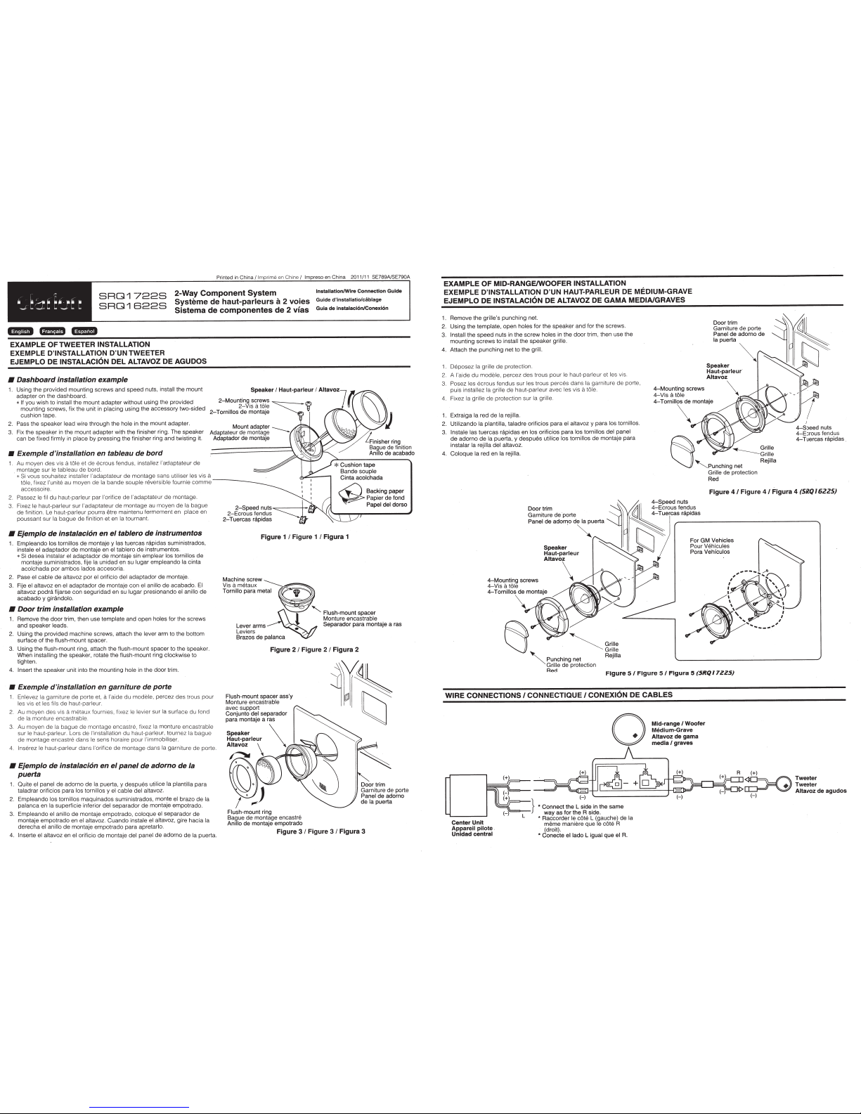
EXAMPLE
OF
TWEETER
INSTALLATION
EXEMPLE
D'INSTALLATION
D'UN TWEETER
EJEMPLO DE
INSTALACION
DEL
ALTAVOZ
DE
AGUDOS
•
Dashboard
installation
example
1.
Using the provided mounting screws and
speed
nuts,
install the mount
adapter on the dashboard
Speaker
I
Haut~parleur
I
Altavoz
2-Mounting
screws
*
If
you wish to
install the mount
adapter
without using the provided
mounting screws, fix the unit in
plac
i
ng
using the accessory two-sided
cushion tape.
2.
Pass the speaker lead
wire through the hole in the mount adapter.
2-Vi
sa
tole
~~
2-
T
ornillos
de montaje
"'V
3.
Fix the speaker in the mount adapter with the finisher ring. The speaker
can be fixed firm ly in
place
by
pres
si
ng
the finisher ring
and
twisting it.
Adaptate~
0
du;~a~~~~~
----
Adaptador de montaje
•
Exemple
d'installation
en
tableau
de
bard
1
Au
moyen
des
vis
a
tOle
et de ecrous fendus,
installez
l'adaptateur
de
montage sur
le
tableau
de
bard.
*
Si vous souhaitez
installer l'adaptateur
de montage sans utiliser les
vis
a
t61e,
fix
ez
l'unite
au moyen de
Ia
bande
souple reversible fournie
comme
____
_
accessoire
Passez
le Iii
du haut-parleur par !'orifice de l'adaptateur
de
montage.
Fixez
le
hau
t-p
arleur sur l'adaptateur
de
montage
au
moyen de
Ia
bague
de finition. Le
ha
ut
-p
arleur pourra
l§tre
maintenu fermement en place en
poussant sur
Ia
bague
de finition et en
Ia
tournant.
•
Ejemplo
de
instalacl6n
en
el
tablero
de
instrumentos
1.
Empleando los
tornillos
de
montaje
y
las
tuercas
r3pidas
suministrados,
instale
el
adaptad
or
de
montaje en el
tablero
de
instrumentos.
*
Si
desea
instalar
el adaptador
de
montaje sin emplear
los tornillos de
montaje suministrados, fije
Ia
unidad en su
Iugar
e
mpleando
Ia
cinta
acolchada
par
ambos
Iadas
accesoria.
2.
Pase
el
cable
de
altavoz par
el
orificio
del
adaptador
de
montaje.
3.
Fije
el
altavoz en
el
adaptador
de
montaje con
el
anillo
de acabado.
El
altavoz
podra
fijarse con seguridad en
su
Iugar
presionando
el
anillo
de
acabado
y
gir8.ndolo.
•
Door
trim
installation
example
1.
Remove the door trim, then use template and open holes for the screws
and
speaker leads.
2.
Using
the provided machine screws, attach the lever
arm to the bottom
surface of the flush-mount spacer.
3.
Using
the flush-mount ring, attach the flush-mount spacer to
the
spea
ker.
When installing the
spe
aker, rotate the flush-mount ring clockwi se to
tighten.
4.
Insert
the speaker unit into the mounting hole in the door trim.
•
Exemple
d'installation
en
garniture
de
porte
1
En
levez
Ia
garniture
de
porte et,
a
l'aide
du
modele,
percez des trous pour
les
vis et
les
fi
ls
de
ha
ut
-parleur.
2.
Au moyen
des
vis
a
me
taux fourn ies, fixez
le
levier
su
r
Ia
surface du fond
de
Ia
rnonture enc astr able .
Au moyen
de
Ia
bagu
e de montag e encastre, fixez
Ia
monture encastrable
su
r
le
haut-parleur. Lars de
!'
installation
du haut-parleur, tournez Ia
bague
de montage encastre dans le sens horaire pour l'immobil iser.
4
lnserez le
haut-parleur dans
!'
orifice
de montage dans
Ia
garniture
de
porte
•
Ejemplo
de
instalac/6n
en
el
panel
de
adorno
de
Ia
puerta
1. Quite
el
panel de adorno de
Ia
puerta, y
despues
uti
lice Ia plantilla
para
taladrar orificios para
los tornillos
y
el
cable
del
altavoz.
2.
Empleando
los tornillos
maqu
inados suministrados, monte
el
brazo de
Ia
pal
anca
en
Ia
superficie inferior
del
separador
de
montaje empotrado.
3.
Empleando
el anillo
de
montaje empotrado, coloque el separador de
montaje empotrado en
el
altavoz. Cuando instale
el
altavoz, gire hacia
Ia
derecha
el
anillo
de
montaje empotrado para apretarlo.
4. lnserte
el
altavoz en
el
orificio
de
montaje
del
panel
de
adorno de
Ia
puerta.
Figure
1
I
Figure
1
I
Figura
1
Figure
2
I
Figure
2
I
Figura
2
Flush-mountspacerass'y
~'
~;~
~tj
Monture
encastrable
~~
~
~~
avec support
Conjunto
del
separador
para montaje a ras
Speaker
\
Haut-parleur
A~
\
="'"'""""'"''
~r
I ..
.J
Flush-mount ring
Bague de montage encastre
Anillo
de montaje empotrado
Figure 3
I
Figure 3
I
Figura 3
EXAMPLE
OF MID-RANGE/WOOFER INSTALLATION
EXEMPLE
D'INSTALLATION
D'UN HAUT-PARLEUR DE
MEDIUM-GRAVE
EJEMPLO DE
INSTALACION
DE
ALTAVOZ
DE
GAMA
MEDIA/GRAVES
1.
Remove the
grille's
punching
net.
2.
Using the template, open holes for the speaker and for the screws.
3.
Install
the speed nuts
in
the
screw
holes
in
the door trim, then use the
mounting screws to
install
the
speaker
gri
ll
e.
4.
Attach the
punching
net to the
grill.
1.
DBposez Ia
gr
ille
de
protection.
2. A !'ai
de
du
mode
le,
percez
de
s trous pour
le
haut-parleur et les vis.
3.
Posez
les ecrous
fendus sur
les
trous perces
dans
Ia
garniture
de
porte,
pu
is
installez Ia grille de haut-parleur avec les vis
8
t61e
4-Mounting
screws
4-Vis
a
tOle
g~~~i!~;';;deporte
~~~~~
Panel de adorno de
Ia
puerta
Speaker
Haut-parleur
Altavoz
\
4.
Fixez
Ia
gr
il
le
de protection sur
Ia
grille
4-
Tomill\
montaje
1.
Extraiga
Ia
red de
Ia rejilla.
2.
Utilizando
Ia plantilla,
taladre orificios para
el
altavoz y para
los tornillos.
3.
lnstale las
tuercas rapidas en
los
orificios para los tornillos
del
panel
de
adorno
de
Ia
puerta, y
despues
utilice los tornillos
de
montaje para
instalar
Ia rejilla del
altavoz.
----Grille
Gnlle
4.
Coloque
Ia
red en
Ia rejilla.
'Punching
net
Rejilla
Grille
de protection
Red
Figure
41
Figure
4/
Figura 4
(5RQ/6225)
Ooortnm
j~~
~
E~~~o
0
~s~~~~us
~=~~~~~~
:;o~~:~~uerta
~~~
Tuercars_r_•P_'d_a_s---------------..
~
For GM
Veh1cles
Speaker
~
II
N
Pour
Veh1cules
Haut-parleur
~
Pora Vehfculos
Attavo\
Figure
5/
Figure
5/
Figura
5
(5RQ
17
225)
WIRE CONNECTIONS
I
CONNECTIQUE
I
CONEXION
DE
CABLES
0
Mid-range/Woofer
Medium-Grave
Altavoz
de
gama
media
I
graves
Page 2
_,,.
CLARION PRODUCT
•
For USA
Dear Customer:
,
Congratulations on your purchase of a
you'll
that
There are many benefits to registering your product.
www.clarion.com
have made product registration
We
is short and easy to
product information.
Register at
4
if!.ifN*
and Canada
enjoy your
to register your
www.clarion.com
.
• INFORMATIONS
Pour les Etas
Cher client:
Unis et le
only
Clarion
complete. Once
DE
REGISTRATION
www.clarion.com
Clarion mobile electronic products.
experience.
Clarior:l
simple
you're registered, we can keep you informed of important
it's easy to keep your Clarion product up to date.
-
product.
with our easy to use website. The registration form
L'ENREGISTREMENT
Canada
seulement
www.clarion.com
INFORMATION
are confident
We
invite you to visit our website at
We
PRODUITS CLARION
DE
Nous vous remercions d'avoir achete ce produit electronique mobile Clarion. Nous sommes
confiants que vous apprecierez votre experience Clarion.
,
visiter notre site
enregistrer votre produits. Nous vous invitons
y a beaucoup d'avantage
II
www.clarion.com
Web
tache d'enregistrement de produit
Nous avons facilite
formulaire
Web.
enregistrer, nous pouvons vous tenir informe des informations important de produits.
Enregistrer
Le
www.clarion.com
a
Ia
d'enregistrement est court et
a
pour enregistrer votre produit
facile
c'est facile
-
de mettre
Clarion.
facile grace
simple
completer.
a
jour votre produit
a
et
Lorsque vous
a
notre
a
Clarion
site
etes
@+'.!.!'
CLARION
• INFORMACION
Para USA
Querida Cliente:
Felicitaciones par
us ted gozara de
Hay muchas ventajas
internet
Hemos hecho
de completar. Una vez que lo
producto.
Registrese
y Canada nomas
su
su
www.clarion.com
el registro de producto facil
www.clarion.com -
en
DEL
compra de producto electr6nico
experiencia con
registrar
al
para registrar su producto de
PRODUCTO
REGISTRO
www.clarion.com
producto de
el
producto.
su
registre, podremos proporcionarle
facil
es
DE
Clarion.
m6vil
Clarion.
invitamos a que visite nuestro sitio
Le
nuestro sitio. La forma de registro es corta y
en
mantener
su
de
Clarion.
producto de
DE
Estamos seguros que
informacion de
Ia
Clarion actualizado.
en
su
facil
285-201 7-00
Page 3

clarion
produit
Ce
fabrication
marchand autorise
Tous
defauts
Clarion
pour
cablages, fils
materiel
de
vendu par un marchand autorise
une
Clarion; les
et
GARANTIE · LIMITEE
Pour
an
(1)
d'un
duree
items tels les
autres accessoires
fabrication pour une
de
ET
Canada
le
compter
a
Clarion achetes
et
piles
duree
Etats-Unis seulement
les
Clarion
de
sont
est garanti contre
vente
de
date
Ia
couverts
de
par
chez un marchand autorise
quatre-vingt-dix
DE 1 AN CLARION
defauts
tous
initiale lorsque l'achat
6 mois suivants
une garantie
(90}
de
Clarion,
jours suivant
de
materiel
de
est effectue chez un
sont garantis contra tous
date
Ia
et
date d'achat.
Ia
d'achat
initiale.
ACHAT DE
TOUT
SOUMIS
Les conditions
ou
1.
2. Cette Garantie
3. Cette Garantie Limitee
4.
5. La responsabilite
6.
7.
8.
A
Clarion
UNE
SOUS GARANTIE
DE
DES
personne ou entreprise qui
ou utilisation incorrects ou
installes, ajustes ou repares
Cette Garantie Limitee ne couvre
manutention
du
Ce
tous
dommages
TOUS PRODUITS CLARION ACQUIS
CLARION, INCLUANT TOUS ACHATS VIA
AUTORISE
EN
PERMETTENT PAS
LIMITEE QUI S'APPLIQUE
AUCUNE
CI-DESSUS,
CAS ETRE
OU L'IMPOSSIBILITE D'UTILISATION DU
PERMETTENT PAS
CAS
S'APPLIQUER
Canada
PREUVE DE DATE
SERVICES AUTORISES
ADRESSES ENUMEREES CI-BAS.
produit,
produit
frais
ACCORD AVEC
DE DOMMAGES
PRODUITS CLARION
RESTRICTIONS
DES
cette garantie
de
lnc."Ciarion"
CE
DE
Limitee
pour
est
qui
est
doit
transport doivent
de
survenue
PAR
GARANTIE IMPLICITE
ET CE,
TENUE RESPONSABLE DES PERTES OU
A
sera
n'est
retrait ou
le
Clarion
de
sujet uniquement
retourne
lors
CLARION,
LES LIMITATIONS DEFINIES PAR
L'ELIMINATION DES GARANTIES SOUS CES CONDITIONS, LAPERIODE
ACCORD
EN
LIMITER
DE
DIRECTS OU INDIRECTS, CES LIMITATIONS OU EXCLUSIONS
vous.
DE GRANANTIES DECRITES CI-DESSOUS.
limitee
sous cette garantie limitee
D'ACHAT
PRODUIT.
CLARION
PAR
annulee
pas
n'est
aucunement
numeros
les
que
autrement
pas
Ia reinstallation.
sous cette Garantie
son
dans
etre prepayes. Clarion
transport.
du
SONT
NE
PRODUIT SERA
AU
NE POURRA S'ETENDRE
AVEC LES LIMITES DEFINIES PAR
DUREE
LA
EFFECTUE
!'implication
et
MARCHAND
D'UN
DES INFORMATIONS
dommage
si un
accredite
applicable
de
qu'indique
interferences electrostatiques,
les
discretion
Ia
a
emballage
L'ENTREMISE
PAR
UN MARCHAND VIRTUEL
COUVERTS
PAS
PRODUIT. PUISQUE CERTAINS ETATS OU PROVINCES
DES
CHEZ
responsabilite
Ia
de
suivantes:
les
sont
AUTORISE
SUPPLEMENT
OBTENUES EN
PEUVENT
comme
serie
Umitee
d'origine
QUINZE(15) J.OURS
DE
GARANTIES IMPLICITES,
ETRE
survenu au bien
est
un Centre
un produit sujet
a
eta
ont
Clarion.
par
est
Clarion.
de
ou
n'assumera aucune
AUTRE QUE PAR UN MARCHAND
PAR
LOI. DANS
LA
DOMMAGES
de
modifies, obstrues ou effaces, ou qui a
limitee uniquement
equivalent.
LES GARANTIES LIMITEES DE
AU-DELA
DIRECTS OU INDIRECTS DUS
CLARION
MARCHAND
UN
NON-AUTORISE CLARION
Clarion
de
AIRES
lors
Service
l'abus, negligence,
a
electriques
colis
Le
responsabilite
(ACHAT
LE CAS OU LES LOIS APPLICABLES
PARTIR
A
LA
DE
LOI. CLARION NE POURRA
LA
OU
Corporation
REQUISE POUR SERVICE
EST
CONCERNANT LES CENTRES
CONTACTANT
service effectue
d'un
Garantie
et
ni
reparation ou au remplacement
Ia
a
doit
INTERNEl} QUI N'EST PAS
LA
DE
PERIODE
LIMITER
DE
America
of
CLARION
par
Clarion.
accidentes,
ete
frais relies
les
entierement assure
etre
cas
en
AUTORISE
CLARION,
DATE D'ACHAT
GARANTIE DECRITE
DE
RESPONSABILITE
LA
PEUVENT NE PAS
a
perte ou
de
GARANTIE
DE
EN
L'UTILISATION
A
NE
SERA
UNE
A
une
install'
mal
raccordes,
Ia
PAR
CE,
ET
NE
INITIALE.
AUCUN
et
EN
Service
VOUS
Manager
9. CETTE
DROITS SUPPLEMENTAIRES SELON VOTRE LIEU
Les
10.
Si
.
11
avec
aux
GARANTIE
de l'etat de
lois
vous eprouvez
Clarion
produits
Aux Etats-Unis:
Clarion Corporation of America
Attn:Customer
6200
1-800-GO-CLARION
www.clarion.com
LIMITEE
California regissent
Ia
problemas
des
visitez notre site Web
ou
Clarion.
Gateway Drive Cypress,
DONNE
performance
de
a
CA 90630
DES
totalement cette garantie limitee,
du
l'adresse ci-dessous afin
DROITS
LEGAUX
RESIDENCE.
DE
produit pendant
PRECIS. VOUS POUVEZ POSSEDER DES
execution.
son interpretation et sa mise
garantie,
resolution
une
Service
de
Inc.
periode
Ia
d'obtenir
Canada:
Au
Clarion Canada
Centre de
2239 Winston Park Drive
Oakville, Ontario
(905)829-4600
www.clarion.com
de
et Garantie
5R1
L6H
veuillez communiquer
tout
en
probleme relie
Page 4

281-0639-01 2008/9
CLARION 1 YEAR LIMITED WARRANTY
For USA and Canada only
This Clarion
workmanship
the battery pack,
by an authorized Clarion dealer.
Ail Clarion cables, wires and
all defects
purchase.
ALL
PURCHASES
TO
FURTHER
The conditions
under this Limited Warranty are as
1 . PROOF OF DATE
WARRANTY
THE
2. This Limited Warranty will
Service Center results in
3. This Limited Warranty
or which has had the serial
adjusted
This Limited Warranty
cleaning
5.
The soie responsibility
repiacernent
product
for
in
materials and
WARRANTY
of
SERVICE
ADDRESS
or
repaired, other than in
or
adjustments,
of
purchased
a period
which
are covered
OF
CLARION
this Limited Warranty and
OF
PURCHASE
LISTED BELOW.
does
does
the product, at
from
of
one
other
workmanship
RESTRICTIONS
OF
THIS
become
damage
not
number
not
or
labor
of
C1anon
an
authorized Clarion dealer are warranted against all
(1)
year
from
the
date
of
original purchase
for 6 months
accessories if purchased from an authorized Clarion dealer are warranted against
for
PRODUCTS
follows
PRODUCT.
to
apply
cover
under
the
: ·
FROM
void if service performed
the
product.
to
altered,
accordance
car
costs
for
this Limited Warranty shall
sole discretion
from
ninety
FROM
AS
DESCRIBED
the
extent
AN
AUTHORIZED
CENTERS
any
product
defaced
with
static
or
the removal
the
date
of
purchase, when purchased
(90)
days
unless otherwise specified
NON-AUTHORIZED
BELOW.
of
responsibility
CLARION
MAY
BE
by
anyone
which has been
or
removed,
the
instructions furnished
other
electrical interferences,
or
reinstallation
of
Clarion.
OBTAINED
or
be
other
than
CLARION
of
Clarion Corporation
DEALER
BY
CONTACTING
other
than an approved Clarion Warranty
subject
which
limited
has been
of
the unit
to
misuse, neglect
by
Clarion.
tape
to
the
defects
consumable
from
DEALERS
WILL
BE
connected,
head
for
repair.
repair
of
in materials and
parts, such as
from
AND
the
date
of
ARE
of
America
REQUIRED
CLARION
or
accident,
installed,
or
laser
pick-up
the
product
installed
original
SUBJECT
("Clarion")
FOR
AT
or
6.
Product rnust be shipped
v;ill
not
c:arion
7 CLARION PRODUCTS
INCLUDING
CLARION
ALLOWED
ELIMINATION OF
PERIOD
8.
ALL
IMPLIED WARRANTIES EXCEPT TO
GREATER DURATION
SHALL
THE USE OR
ON
CONSEQUENTIAL
THIS
R!GHTS
10. The
11. Should you have any difficulties
Clarion
Clarion
CLARION
HOW
LIMITED
'aws
or
Customer
assume any responsibility for any loss
ANY
AND
DEALER,
BY
APPLICABLE
WARRANTIES
SHALL
WHICH
of
BE
BE
INABILITY
LONG
AN
WARRANTY
VARY
the
State
visit
our
Service at
!n
USA:
Clarion Corporation
,A.ttn:Customer Service Manager
6200 Gateway Drive
Cypress,
1-800-GO-CLARION
www.clarion.com
in
its original carton or equivalent 9arton, fu!!y insured,
PURCHASED
ALL
PURCHASES
SHALL
DEEMED
IMPLIED
DAMAGES,
web
NOT
THAN
LIABLE
TO
USE
GIVES
FROM
of
California shall
site
for
the
CA
90630
LAW. IN
TO
THE
FOR
WARRANTY
FROM A SOURCE
VIA
THE
BE
COVERED
THE
UNDER
BE
FIFTEEN (15) DAYS
WARRANTY
ANY
LOSS OR
THE
PRODUCT.
THE
ABOVE LIMITATIONS OR
YOU
SPECIFIC
STATE TO STATE.
fjovern
with
the
performance
a listing
of
address listed
of
America
BY
EVENT
THESE
THE
EXTENT
PERIOD SET FORTH ABOVE.
LASTS
and control this Limited Warranty, its interpretation
Authorized VVarranty Service Centers
below
or
damage
OTHER
INTERNET
ANY
CLARION
AND
TO
CIRCUMSTANCES,
PROHIBITED
DAMAGE,
BECAUSE
OR
EXCLUSIONS
LEGAL
of
this
for any service rtelp you
incurred
THAN
FROM A NON
THE
EXTENT
FROM
THE
DIRECT
SOME
EXCLUSIONS
RIGHTS,
product
LIMITED
with
shipping
in
shipping.
AN
AUTHORIZED
INTERNET
WARRANTY
APPLICABLE
THE
APPLICABLE
DATE
OF
ORIGINAL
BY
APPLICABLE
UNDER
OR
CONSEQUENTIAL,
STATES
OR LIMITATIONS OF
AND
during the warranty period, please cail I
In
Clarion Canada Inc.
Vvarranty Service Center
2239
Oakville, Ontario L6H
(905) 829-4600
www.clarion.com
DO
NOT
MAY
NOT
YOU
MAY
ALSO
in
your
area. You
may
need with Clarion products. I
Canada:
Winston Park Drive
charges prepaid .
CLARION
AUTHORIZED
TO
THE
EXTENT
LAW
PROHIBITS
LIMITED
PURCHASE.
LAW
NO
CIRCUMSTANCES
ALLOW
INCIDENTAL
APPLY
HAVE OTHER
5R1
WA.RRANTY
SHALL
ARISING
LIMITATIONS I
TO
YOU. 1
and
enfor
may
also
DEALER,
HAVE NO
OUT
OR I
cement
contact
l
OF I
1
..•
:
I
I
 Loading...