


 Loading...
VARIANT 260
VARIANT 260 ROTO CUT VARIANT 280
VARIANT 280 ROTO CUT
Operating instructions
|
|
|
|
|
|
|
|
|
|
|
|
|
|
|
|
|
|
|
|
|
|
|
|
|
|
n |
s |
! |
|
|
|
|
|
|
|
|
|
|
|
|
|
|
|
|
|
|
|
|
|
|
|
|
|
o |
|
||
|
|
|
|
|
|
|
|
|
|
|
|
|
|
|
|
|
|
|
|
|
|
|
t |
i |
|
|
||
|
|
|
|
|
|
|
|
|
|
|
|
|
|
|
|
|
|
|
|
|
l |
a |
|
|
|
|||
|
|
|
|
|
|
|
|
|
|
|
|
|
|
|
|
|
|
|
|
|
|
|
|
|
|
|||
|
|
|
|
|
|
|
|
|
|
|
|
|
|
|
|
|
|
|
eg |
u |
|
|
|
|
|
|
||
|
|
|
|
|
|
|
|
|
|
|
|
|
|
|
|
|
|
|
|
|
|
|
|
|
|
|
||
|
|
|
|
|
|
|
|
|
|
|
|
|
|
|
|
|
ty |
r |
|
|
|
|
|
|
|
|
|
|
|
|
|
|
|
|
|
|
|
|
|
|
|
|
|
|
|
|
|
|
|
|
|
|
|
|
|
||
|
|
|
|
|
|
|
|
|
|
|
|
|
|
a |
f |
e |
|
|
|
|
|
|
|
|
|
|
|
|
|
|
|
|
|
|
|
|
|
|
|
|
|
s |
|
|
|
|
|
|
|
|
|
|
|
|
|||
|
|
|
|
|
|
|
|
|
|
|
|
|
|
|
|
|
|
|
|
|
|
|
|
|
|
|||
|
|
|
|
|
|
|
|
|
|
|
|
ve |
|
|
|
|
|
|
|
|
|
|
|
|
|
|
||
|
|
|
|
|
|
|
|
|
|
|
|
|
|
|
|
|
|
|
|
|
|
|
|
|
|
|
||
|
|
|
|
|
|
|
|
|
s |
e |
r |
|
|
|
|
|
|
|
|
|
|
|
|
|
|
|
|
|
|
|
|
|
|
|
|
|
|
|
|
|
|
|
|
|
|
|
|
|
|
|
|
|
|
|
|||
|
|
|
|
|
|
|
|
b |
|
|
|
|
|
|
|
|
|
|
|
|
|
|
|
|
|
|
||
|
|
|
|
|
|
|
o |
|
|
|
|
|
|
|
|
|
|
|
|
|
|
|
|
|
|
|
||
|
|
|
|
|
|
d |
|
|
|
|
|
|
|
|
|
|
|
|
|
|
|
|
|
|
|
|
||
|
|
|
|
|
n |
|
|
|
|
|
|
|
|
|
|
|
|
|
|
|
|
|
|
|
|
|
||
|
|
|
|
a |
|
|
|
|
|
|
|
|
|
|
|
|
|
|
|
|
|
|
|
|
|
|
||
|
|
|
d |
|
|
|
|
|
|
|
|
|
|
|
|
|
|
|
|
|
|
|
|
|
|
|
||
|
|
a |
|
|
|
|
|
|
|
|
|
|
|
|
|
|
|
|
|
|
|
|
|
|
|
|
||
|
e |
|
|
|
|
|
|
|
|
|
|
|
|
|
|
|
|
|
|
|
|
|
|
|
|
|
||
R |
|
|
|
|
|
|
|
|
|
|
|
|
|
|
|
|
|
|
|
|
|
|
|
|
|
|
||
|
|
|
|
|
|
|
|
|
|
|
|
|
|
|
|
|
|
|
|
|
|
|
|
|
|
|
||
|
|
|
|
|
|
|
|
|
|
|
|
|
|
|
|
|
|
|
|
|
|
|
|
|
|
|
|
1 Introduction

|
Introduction |
|
|
INTRODUCTION |
These operating instructions for round balers |
|
VARIANT 260/260 RC and VARIANT 280/280 RC |
|
(valid from 73000005; 73200011) were primarily |
|
written for the machine operator and inform about use, |
|
adjustment and operation of the round baler. |
|
Please follow the guidelines on correct care and |
|
maintenance of your round baler to ensure permanent |
|
availability and a long service life of the round baler. |
|
Have your round baler inspected by your CLAAS |
|
service center immediately after harvest within the |
|
framework of these winter storage recommendations. |
|
Deficiencies in maintenance or incorrect operation |
|
lead to a drop in performance and result in time losses. |
|
Use our experience and latest knowledge in long stalk |
|
harvest implemented in this round baler by correct |
|
operation and thorough maintenance, and your round |
|
baler will always produce excellent results. |
|
Your CLAAS Service Department |
000 298 456 6 - BA VARIANT 260/280 - 260/280 RC |
1.1.1 |

Introduction
1.1.2 |
BA VARIANT 260/280 - 260/280 RC - 000 298 456 6 |
2 Contents

Contents
CONTENTS
1. Introduction
Introduction ............................................................................ |
1.1.1 |
2. Contents |
|
3. General notes |
|
Road traffic ............................................................................ |
3.1.1 |
To be observed especially ..................................................... |
3.2.1 |
Type plate ........................................................................ |
3.3.1 |
Machine serial number .................................................... |
3.3.1 |
4. Safety precautions |
|
Safety precautions ................................................................. |
4.1.1 |
Personal injury may result if these safety precautions |
|
are not followed ............................................................... |
4.1.1 |
Safety signs ..................................................................... |
4.1.3 |
Transporting baler on a public thoroughfare .................... |
4.1.3 |
Transporting baler on a public thoroughfare .......................... |
4.1.5 |
Recommended warning lights ......................................... |
4.1.5 |
Preparing for transport ..................................................... |
4.1.5 |
4. |
|
4. Safety signs |
|
5. Technical data |
|
CLAAS Variant 260/280 / Variant 260/280 RC ...................... |
5.1.1 |
Intake elements ............................................................... |
5.1.1 |
Cutting device .................................................................. |
5.1.1 |
Bale compression ............................................................ |
5.1.2 |
Wrapping facility .............................................................. |
5.1.2 |
Wheels ............................................................................. |
5.1.2 |
Hydraulics ........................................................................ |
5.1.2 |
Required tractor hydraulics .............................................. |
5.1.3 |
Hydraulic pressure ........................................................... |
5.1.3 |
Electrics ........................................................................... |
5.1.3 |
CLAAS Variant 260/280 / Variant 260/280 RC ...................... |
5.1.4 |
Dimensions of the round baler ......................................... |
5.1.4 |
CLAAS Variant 260/280 / Variant 260/280 Roto Cut ............. |
5.1.5 |
Safety installations ................................................................. |
5.1.5 |
Shearing screws .............................................................. |
5.1.5 |
Overload clutch ................................................................ |
5.1.5 |
6. Design and working principle |
|
Machine overview .................................................................. |
6.1.1 |
Power train ...................................................................... |
6.1.3 |
Shear coupling and freewheeling propshaft .................... |
6.1.3 |
Cam clutch – propshaft .................................................... |
6.1.3 |
Pick up ............................................................................. |
6.1.4 |
Cutter ............................................................................... |
6.1.5 |
Dummy blade holder (optional) ....................................... |
6.1.5 |
Baling chamber ................................................................ |
6.1.6 |
Wrapping of bales ............................................................ |
6.1.6 |
Bale ejector ...................................................................... |
6.1.7 |
Storage of round bales .................................................... |
6.1.7 |
Rotor shut down clutch .................................................... |
6.1.7 |
Manual reversing of rotor ................................................. |
6.1.8 |
Twine boxes .................................................................... |
6.1.8 |
Steps ............................................................................... |
6.1.9 |
Fire extinguisher (country option) .................................... |
6.1.9 |
Active hydraulic system ................................................... |
6.1.9 |
Automatic chain lubrication ........................................... |
6.1.10 |
Side indicator (optional) ................................................ |
6.1.11 |
Control box .................................................................... |
6.1.11 |
7. Before starting operation
Check and pay attention to the following before |
|
starting operation of the machine .......................................... |
7.1.1 |
Hitching up the baler ............................................................. |
7.2.1 |
Coupling the propshaft to the baler ................................. |
7.2.1 |
Propshaft with clamping cone lock .................................. |
7.2.2 |
Installing propshaft with CC-lock ..................................... |
7.2.2 |
Parking support ............................................................... |
7.2.2 |
Before coupling the round baler ...................................... |
7.2.3 |
After coupling the round baler ......................................... |
7.2.3 |
Coupling to the trailer coupling ring ................................. |
7.2.3 |
Greasing the towing eye ................................................. |
7.2.4 |
Connecting the propshaft to the tractor |
|
(for trailer coupling) ........................................ |
7.2.4 |
Shortening the propshaft ................................................. |
7.2.6 |
Preventing the propshaft guards from rotating |
|
with the drive shaft .......................................................... |
7.2.7 |
Coupling to the towing hitch ............................................ |
7.2.8 |
Connecting the propshaft to the tractor ........................... |
7.2.9 |
Attaching to the ball head .............................................. |
7.2.10 |
Connecting the cables ........................................................... |
7.3.1 |
Control box ...................................................................... |
7.3.1 |
Power supply ................................................................... |
7.3.1 |
Travel lights ..................................................................... |
7.3.1 |
Connecting hydraulic hoses ............................................ |
7.3.2 |
Tailgate opening speed ................................................... |
7.3.2 |
Before transport ..................................................................... |
7.4.1 |
8. Setting up the baler
Collecting ............................................................................... |
8.1.1 |
Height adjustment of pick-up ........................................... |
8.1.1 |
Adjusting pick-up working height |
|
(Pick-up without support wheels) .................................... |
8.1.1 |
Pick-up with support wheels ............................................ |
8.1.2 |
Support wheels ............................................................... |
8.1.2 |
Cutting device |
|
(VARIANT 260/280 RC) ........................................................ |
8.2.1 |
Dummy knives ................................................................. |
8.2.1 |
Installing and removing knives ........................................ |
8.2.1 |
Placing the blades into the dummy blade holder ............ |
8.2.2 |
Locking the knives ........................................................... |
8.2.3 |
Pressing bales ....................................................................... |
8.3.1 |
Baling pressure adjustment ............................................. |
8.3.1 |
Adjusting the bale diameter ............................................. |
8.3.1 |
Adjusting the soft core diameter ...................................... |
8.3.2 |
Wrapping ............................................................................... |
8.4.1 |
Net wrapping ................................................................... |
8.4.1 |
Inserting the net .............................................................. |
8.4.1 |
Adjusting the number of net windings ............................. |
8.4.5 |
000 298 456 6 - BA VARIANT 260/280 - 260/280 RC |
2.1.1 |

Contents
Twine wrapping ................................................................ |
8.4.6 |
Threading the wrapping twine .......................................... |
8.4.6 |
Adjusting number of twine windings .............................. |
8.4.10 |
Adjusting the twine windings at the outer edges |
|
of the bale ...................................................................... |
8.4.11 |
Tying with three threads ................................................ |
8.4.12 |
Preparing the twine eyelet ............................................. |
8.4.12 |
Tying with three threads ................................................ |
8.4.12 |
Baler adjustment under extreme silage conditions ................ |
8.5.1 |
Removal of belt guides .................................................... |
8.5.1 |
Installation of belt guides ................................................. |
8.5.1 |
Round baler with twine and net wrapping .............................. |
8.6.1 |
Changing to twine wrapping ............................................ |
8.6.1 |
Adjusting drive for twine wrapping ................................... |
8.6.1 |
Applying the V-belt brake ................................................. |
8.6.1 |
Changing to net wrapping ................................................ |
8.6.2 |
Adjusting drive for net wrapping ...................................... |
8.6.2 |
Releasing V-belt brake .................................................... |
8.6.2 |
Baling of silage ................................................................ |
8.6.2 |
Installing dummy knife holder (optional) on |
|
VARIANT ROTO CUT ..................................................... |
8.6.3 |
9. Operation
Starting operation of round baler ........................................... |
9.1.1 |
Charging the baling chamber ........................................... |
9.1.2 |
Side indicator ................................................................... |
9.1.3 |
Automatic wrapping ......................................................... |
9.1.4 |
Tying delay ...................................................................... |
9.1.4 |
Delay function .................................................................. |
9.1.4 |
Twine wrapping: Setting the delay ................................... |
9.1.4 |
Net wrapping: Setting the delay ....................................... |
9.1.5 |
Wrapping and ejection of bales ....................................... |
9.1.6 |
Placement of bales .......................................................... |
9.1.8 |
Output of bales without bale ejector ................................ |
9.1.8 |
Bale counter ..................................................................... |
9.1.8 |
Round baler with net wrapping ........................................ |
9.1.8 |
Round baler with twine and net wrapping ........................ |
9.1.8 |
Round baler with twine wrapping ..................................... |
9.1.8 |
Manual overload of automatic wrapping .......................... |
9.1.9 |
Triggering early wrapping ................................................ |
9.1.9 |
Delaying the wrapping process: ....................................... |
9.1.9 |
Cutting device (ROTO CUT) .......................................... |
9.1.10 |
Slewing the blades in ..................................................... |
9.1.10 |
Slewing the blades out ................................................... |
9.1.10 |
Adjusting the volume of the audible warning signal ....... |
9.1.10 |
Blockage of the round baler ................................................... |
9.2.1 |
Cam clutch – propeller shaft ............................................ |
9.2.1 |
Rotor reversing facility |
|
(VARIANT 260/280 / 260/280 RC) ................................... |
9.2.1 |
Fault, cause or remedy .......................................................... |
9.3.1 |
Twine wrapping ................................................................ |
9.3.1 |
Net wrapping .................................................................... |
9.3.2 |
10. After use
Unhitching the baler ............................................................. |
10.1.1 |
Wheel chock .................................................................. |
10.1.1 |
Parking support .............................................................. |
10.1.1 |
Control box .................................................................... |
10.1.2 |
Hydraulic hoses and electrical wiring ............................. |
10.1.2 |
Propshaft ....................................................................... |
10.1.3 |
Gauge wheels ............................................................... |
10.1.4 |
Cleaning of dirt .............................................................. |
10.1.4 |
11. Maintenance
Important notes on maintenance ......................................... |
11.1.1 |
General notes on maintenance ..................................... |
11.1.1 |
Maintenance and lubricant tables ........................................ |
11.2.1 |
Maintenance tables ....................................................... |
11.2.1 |
Lubricant table ............................................................... |
11.2.2 |
Drives .................................................................................. |
11.3.1 |
Shear pin main drive ..................................................... |
11.3.1 |
Shear pin pick-up drive .................................................. |
11.3.1 |
Mitre gear ...................................................................... |
11.3.1 |
Tightening the drive chains ........................................... |
11.3.2 |
Tightening the pick-up drive chain ................................. |
11.3.2 |
Tensioning the drive chain for the feed auger ............... |
11.3.3 |
Adjusting the pressure springs for the pressing roller ... |
11.3.3 |
Adjusting the clamping device for the net blade ............ |
11.3.4 |
Adjusting the disc brake ................................................ |
11.3.4 |
Tightening the chain drive tension springs |
|
(belts and rotor) ............................................................. |
11.3.4 |
Tightening the chain drive tension springs |
|
in the tailgate ................................................................. |
11.3.5 |
Adjusting the tension springs for top tensioning arm ..... |
11.3.5 |
Adjusting the tension springs for bottom tensioning arm 11.3.5 |
|
Tightening the tension spring for the net roll brake bow |
11.3.6 |
Adjusting the spring cylinder for freewheeling drive ...... |
11.3.6 |
Adjusting the bale ejector tension springs ..................... |
11.3.6 |
Adjusting the linkage to the bale ejector limit switch ..... |
11.3.7 |
Drive brake for twine wrapping ...................................... |
11.3.7 |
Adjusting the pressure springs on shut-off coupling ...... |
11.3.7 |
Adjusting the friction clutch pressure springs |
|
(ratchet wheel) (Net wrapping) ...................................... |
11.3.7 |
Adjusting the twine tensioner ........................................ |
11.3.8 |
Settings of the inductive sensors ................................... |
11.3.8 |
Inductive sensor „maximum ball diameter“ .................... |
11.3.8 |
Inductive sensor „closed door“ ...................................... |
11.3.8 |
Hydraulic oil filter |
|
(Machines with filter system) ......................................... |
11.3.9 |
Automatic chain lubrication ......................................... |
11.3.10 |
Adjusting the Linatex guide plate ................................ |
11.3.11 |
Fire extinguisher (optional) .......................................... |
11.3.12 |
Flat belts .............................................................................. |
11.4.1 |
Relieving flat belts ......................................................... |
11.4.2 |
Checking flat belts ......................................................... |
11.4.3 |
Relieving flat belts ......................................................... |
11.4.4 |
Installing flat belts .......................................................... |
11.4.6 |
Belt alignment ................................................................ |
11.4.7 |
Adjusting the scraper, bottom roller ............................... |
11.4.7 |
Tires .............................................................................. |
11.4.8 |
Check tight fit of wheel nuts .......................................... |
11.4.8 |
Checking wheel hub backlash ....................................... |
11.4.8 |
Adjusting the backlash .................................................. |
11.4.8 |
2.1.2 |
BA VARIANT 260/280 - 260/280 RC - 000 298 456 6 |
Contents
Proposals for winter storage ................................................ |
11.5.1 |
12. |
Lubrication chart |
|
Lubricants and notes ........................................................... |
12.1.1 |
|
13. |
Glossary |
|
000 298 456 6 - BA VARIANT 260/280 - 260/280 RC |
2.1.3 |

Contents
2.1.4 |
BA VARIANT 260/280 - 260/280 RC - 000 298 456 6 |
3
General notes

General notes
ROAD TRAFFIC |
The vehicle operator must always have two wheel |
|
chocks on the vehicle. |
|
When driving on public roads with agricultural or |
|
forestry equipment attached, the highway code of |
|
the respective country must be strictly complied |
|
with. |
|
Above all, no bale must be in the round baler. |
|
If parts of the baler, the conditions of which are |
|
clearly specified, are later changed or modified in |
|
such a way that their operation will endanger any |
|
other participants in traffic, the type approval will |
|
become invalid and a new type approval must be |
|
applied for. In this case the Iof working equipment |
|
must be presented to the responsible technical |
|
inspection authority for motor vehicles (e.g. TÜV) for |
|
issuing an expertise (§ 19 para. 2 StVZO). |
|
If you are in doubt that this may be the case, please |
|
contact us as the manufacturer. |
|
If the round baler is pulled after a tractor, especially |
|
the following devices have to be connected: |
|
- The cable of the lighting equipment. |
|
- The cable for power supply. |
|
Before starting to drive the condition of: |
|
- the connection between pulling vehicle and baler |
|
- the lighting equipment must be checked. |
|
If the license plate given to the vehicle owner for |
|
one his tractors is concealed when the baler is |
|
hitched up, attach a picture of this plate, including its |
|
lighting, onto the baler. |
|
The local road traffic regulations may differ in |
|
individual countries. |
|
The maximum speed under the road traffic |
|
regulations for the country of operation must be |
|
observed. However, the hitched baler is designed to |
|
travel at a maximum speed of 25 km/h (16 mph). It |
|
is not permissible to exceed that speed. |
|
|
000 298 456 6 - BA VARIANT 260/280 - 260/280 RC |
3.1.1 |

General notes
|
|
3.1.2 |
BA VARIANT 260/280 - 260/280 RC - 000 298 456 6 |

General notes
TO BE OBSERVED ESPECIALLY |
In order to avoid any dangers all information in |
|
these operating instructions must be read and |
|
applied by all persons using, maintaining, |
|
repairing or inspecting this round baler. Read in |
|
particular the section “Concerning safety”. |
|
The use of spare parts, accessories and |
|
attachments not originally supplied by CLAAS |
|
and not tested and approved by CLAAS may |
|
impair design specific characteristics of CLAAS |
|
machines or have a negative effect on their |
|
functionality, thereby impairing the active and/ |
|
or passive driving as well as the working safety. |
|
CLAAS does not assume liability for damage |
|
resulting from the use of parts, accessories and |
|
attachments not originally manufactured and |
|
supplied by CLAAS. |
|
Technical data, dimensions and weights are |
|
non-binding. The right for changes in the course |
|
of technical development and errors remains |
|
reserved. |
|
The terms front, rear, right and left always apply |
|
in travel direction. |
|
|
000 298 456 6 - BA VARIANT 260/280 - 260/280 RC |
3.2.1 |

General notes
|
|
3.2.2 |
BA VARIANT 260/280 - 260/280 RC - 000 298 456 6 |
General notes
|
|
1 |
A |
C |
|
Type: |
|
|
N° |
|
B |
|
|
|
Année de Fabrication |
|
|
Poids total autorisé en charge |
|
|
USINES CLAAS - FRANCE |
D |
|
57148 - WOIPPY |
|
|
800093 |
|
2 |
|
|
|
3
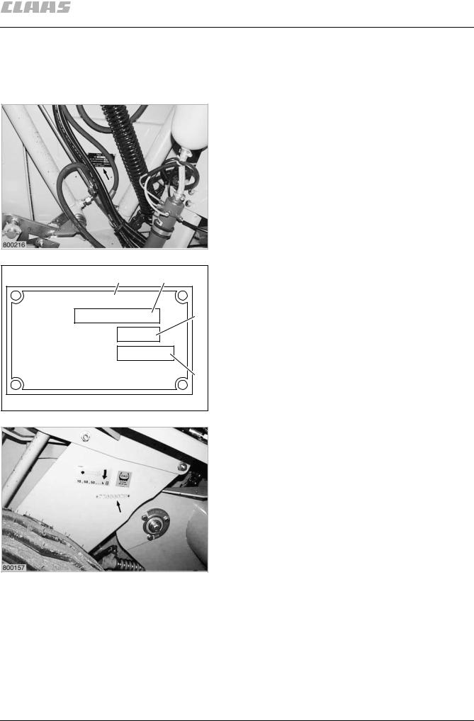
When ordering spare parts or if you have any technical questions please provide the machine number of the round baler together with the respective serial number. This is absolutely necessary in order to avoid wrong spare parts deliveries.
Type plate
The type plate with the machine serial number is fixed to the right hand machine wall.
A = Type
B= Year of construction
C= Machine number
D= Permissible total weight (Fig. 1, 2)
Machine serial number
The machine number is additionally stamped in the tie-bar above the right-hand wheel.
(Fig. 3)
000 298 456 6 - BA VARIANT 260/280 - 260/280 RC |
3.3.1 |

General notes
3.3.2 |
BA VARIANT 260/280 - 260/280 RC - 000 298 456 6 |
4
Safety precautions

SAFETY PRECAUTIONS
For your safety, and those working with you, follow these safety precautions and observe all safety signs on the machine.
In order to provide a better view, certain photographs or illustrations in this manual may show an assembly with the safety shield removed. However, a machine should never be operated in this condition. Keep all shields in place. If shield removal becomes necessary for repairs, replace shield prior to machine operation!
Replace any Danger, Warning, Caution or Instruction Safety signs that are missing or not readable. Location of safety signs are indicated within this manual.
Note!
The figure in () refers to the adjacent picture and indicates the correct location of the safety sign on the machine.
When parts are replaced that have safety signs, make sure you install a new safety sign with each new part.
Note!
New safety signs are available from your CLAAS Dealer.
Attention!
Before using the machine read and understand Operator’s Manual safety messages!
Read and understand all safety signs on the machine.
Learn and practice safe use of controls before operating.
It is your responsibility to understand and follow manufacturers instructions on machine operation, service, and to observe pertinent laws and regulations.
Operator Manuals may be obtained from your CLAAS Dealer.
Safety precautions
Personal injury may result if these safety precautions are not followed
•MAKE SURE no person is allowed on any part of the Baler when tractor is running.
•MAKE SURE all safety shields and covers are installed properly when Baler is operating.
•MAKE SURE all bystanders are in a safe position before starting the tractor or operating Baler.
•MAKE SURE the pickup head is fully lowered before any part of the hydraulic system is disconnected.
•MAKE SURE no one is allowed under the pickup head unless the pickup head is in transport position and securely locked.
•MAKE SURE all safety shields on Baler are in place and secured when any have been removed for servicing, to make adjustments, etc. Remember, these shields are provided for the protection of those working on or around the Baler.
•NEVER STAND in path of Baler while operating.
•KEEP OUT of Baler compartment while operating.
•BE SURE all hydraulic fittings are tightened securely whenever they have been loosened or disconnected. Replace all hoses which have become frayed. Escaping hydraulic oil under pressure can cause personal injury.
•If Baler hydraulic system is equipped with an accumulator, accumulator shutoff valve must be closed before: (a) any part of the hydraulic system is loosened or is to be disconnected, and (b) the Baler is to be transported for any distance.
•TAKE NOTE that hydraulic fluid under pressure escaping from a very small hole can be almost invisible. Use a small piece of cardboard or wood to search/check for possible leaks.
•NEVER use your hands to detect pressure leaks.
•CONSULT A DOCTOR immediately if you sustain an injury by escaping fluids. Serious infection or reactions can develop if proper medical treatment is not administered quickly.
•MAKE SURE all oil or grease is removed from operator’s ladder and platform and other access areas immediately if any is spilled.
000 298 456 6 - BA VARIANT 260/280 - 260/280 RC |
4.1.1 |

Safety precautions
•BE EXTRA CAREFUL to keep hands, feet and loose clothing away from moving parts.
•READ THIS MANUAL and take note of ALL safety precautions included herein.
Attention!
Do not remove, install or make repairs to a tire on a rim. Take tire and rim to the nearest available tire specialist, who have experience and the safety tools. If the tire is not correctly positioned on the rim, or the tire pressure is too high then the tire bead is liable to loosen on one side, resulting in the pressured air to leak out at high speed and with force. This can lead to the risk of the tire flying off and causing serious injury!
A tire can explode during inflation and cause serious injury or death. Never increase air pressure beyond 35 PSI to seat the bead on the rim. Replace a tire if it has a defect. Replace a wheel rim which has cracks, wear or severe rust. Make sure that all the air is removed from a tire before removing the tire from the rim. Never use force on an inflated or partially inflated tire. Make sure the tire is correctly seated before inflating.
Danger!
Check the machine for leaks or any parts that are broken, not working correctly, or missing. Before you start the machine, tighten all caps, dipsticks, battery covers, etc.
Never use gasoline, naphtha or any other volatile material for any cleaning purposes. These materials may be toxic and/or flammable.
Use only metric tools. Other tools may not fit properly. They may slip and cause injury.
Danger!
Before leaving the tractor, stop the engine, and remove the starter key. The gear shift lever must be in neutral and the parking brake engaged.
4.1.2
Attention!
To provide more secure hand and foot mobility, preventing slipping and possible injury, always face the machine when mounting and dismounting.
Danger!
Never operate the engine in a closed building. Proper ventilation is required under all circumstances.
Contact with belts, chains etc. can cause injury. Keep clear.
Attention!
To help prevent personal injuries during operation and maintenance, loose shirts, sleeves or jackets must never be worn by the operator.
Danger!
Before starting the tractor, be sure all operating controls are in neutral. This will ease starting loads on the starter and batteries of the tractor and will eliminate the accidental start up of power driven equipment.
Travel speed should be such that complete control and machine stability is maintained at all times. Where possible, avoid operating near ditches, embankments and holes. Reduce speed when turning, crossing slopes, and on rough, slick, or muddy surfaces.
Danger!
On highways use lighting equipment according to local laws. Keep SMV emblem clean and visible. Replace SMV emblem when damaged or sun faded.
Stop, look and listen before entering public thoroughfare or a highway.
BA VARIANT 260/280 - 260/280 RC - 000 298 456 6

Attention!
Collision of high speed road traffic and slow moving machines can cause personal injury or death.
Stay off slopes too steep for safe operation. Shift down before you start up or down a hill with heavy load. Avoid ”free wheeling”.
Danger!
Provide a first aid kit for use in case of accident.
As a safety precaution, it is suggested one or more fire extinguishers be carried on the Baler at all times. Fire extinguishers must be purchased from Fire & Safety equipment supply store.
Attention!
Look for this symbol to point out important safety precautions. It means BECOME ALERT! YOUR SAFETY IS INVOLVED.
This machine is of metric design. Measurements in this manual are metric with the customary U.S. measurements following. Use only metric hardware and tools as specified.
Replacement Parts:
–When replacement parts are necessary for periodic maintenance and servicing, genuine CLAAS replacements must be used to restore your equipment to original specifications.
–CLAAS will not claim responsibility for usage of unapproved parts and/or accessories and damages as a result of their usage.
000 298 456 6 - BA VARIANT 260/280 - 260/280 RC
Safety precautions
Safety signs
Attention!
Install new safety signs if the old safety signs are destroyed, lost, painted over or can not be read. When parts are replaced that have safety signs, make sure you install a new safety sign with each new part.
Note!
New safety signs are available from your
Dealer or write to:
CLAAS OF AMERICA Inc.
P.O.Box 3008
3030 Norcross Drive
Columbus Indiana 47201
USA.
Transporting baler on a public thoroughfare
Whenever a Baler is to be transported on a public thoroughfare, the following preparation of the Baler should be made:
•Position pickup in the transport position. Close gate, raise pickup and converging wheels, if equipped.
•Make sure warning devices, such as slow moving vehicle emblem, reflectors, etc., are installed, clean and are in good condition.
•Use flashinglights according to local laws. Keep SMV emblem clean and visible. Replace SMV emblem when damaged or sun faded.
•For reference purposes, measure the overall width and height of the Baler. These measurements are particularly important for transporting along narrow roads and where underpasses may be encountered.
•If the Baler hydraulic system is equipped with an accumulator, make sure the accumulator shutoff valve is closed.
4.1.3

Safety precautions
Danger!
Proper tire pressure should be maintained at all times to insure stability during road travel.
Always use a safety chain while transporting baler. Sudden jolts or rocking could cause the drawbar to break. If a rocking motion occurs when transporting, reduce speed until rocking stops. Check rear tractor wheels for any tire tread wear or pressure loss. Refer to operator’s manual for tractor tire pressures.
Use care when towing baler at transport speeds. Reduce speed if the weight of baler exceeds weight of tractor.
When towing baler on public roads, an extended mirror to improve visibility of traffic behind the baler is recommended. Mirrors are available from your dealer.
When the Baler is being transported on a public thouroughfare, the following precautions must be observed:
•Reduce speed before applying the brakes. Using a hydrostatic transmission to slow the vehicle is more effective than merely applying the brakes.
If in doubt regarding local or state/provincial laws pertaining to transportation of farm equipment, consult your local law enforcement agency.
Danger!
Use or warning lights and turn signals are recommended when transporting this equipment on public roads, unless prohibited by state or Local Laws.
A safety lighting kit is available from your CLAAS dealer.
Always use a safety chain when transporting baler on public roads. Transporting baler at speeds in excess of 20 mph (32 km/h) is not recommended.
Use care when towing baler at transport speeds. Reduce speed if the combined weight of baler with bale exceeds weight of tractor. The approved minimal total weight of tractor must not receed 2.5 tons (2500 kg).
The towed baler can be transported without brakesystem, when the approved minimal total weight of tractor is 2.5 tons (2500 kg).
Note!
Install new safety signs if the old are destroyed, lost, painted over or can not be read. When parts are replaced that have safety signs, make sure you install a new safety sign with each new part.
New safety signs are available from your Dealer or write to:
CLAAS OF AMERICA Inc.
P.O. Box 3008
3030 Norcross Drive
Columbus Indiana 47201
USA
TO SHOW TECHNICAL DETAILS OF BALER
COMPONENTS AND ASSEMBLIES IN THIS
OPERATOR’S MANUAL, A NUMBER OF SAFETY
SHIELDS AND PANELS WERE REMOVED FOR
PHOTOGRAPHIC PURPOSES ONLY. ALL
SAFETY SHIELDS AND PANELS MUST BE
INSTALLED BEFORE BALING OPERATIONS
COMMENCE.
4.1.4 |
BA VARIANT 260/280 - 260/280 RC - 000 298 456 6 |

Safety precautions
TRANSPORTING BALER ON A PUBLIC
THOROUGHFARE
Attention!
When transporting the baler on a highway use SMV emblem (PN 514 155.1).
Recommended warning lights
1
Attention!
Use of flashing warning lights and turn signals are recommended when towing this equipment on public roadfs unless prohibited by state or local regulations. An implement safety lighting kit is available from your Dealer.
|
Preparing for transport |
|
Attention! |
|
Always use a safety chain while transporting |
|
baler. Sudden jolts or rocking could cause |
|
the drawbar to break. If a rocking motion |
|
occurs when transporting, reduce speed until |
|
rocking stops. Check rear tractor wheels for |
|
any tire tread wear or air pressure loss. |
|
Refer to operator’s manual for tractor tire |
|
pressures. |
800297 |
2 |
Note!
Route safety chain from baler through hitch and secure to drawbar supporting structure as shown. Remove all slack except what is needed for turns. Do not make sharp turns when transporting baler. Damage could result if tongue strikes tractor tire.
000 298 456 6 - BA VARIANT 260/280 - 260/280 RC |
4.1.5 |

Safety precautions
Danger!
Do not secure baler safety chain to drawbar.
Use care when towing baler at transport speeds. Reduce speed if the combined weight of baler with bale exceeds weight of tractor. The approved minimal total weight of tractor must not receed 6 tons (6000 kg).
The towed baler can be transported without brakesystem, when the approved minimal total weight of tractor is 6 tons (6000 kg).
4.1.6 |
BA VARIANT 260/280 - 260/280 RC - 000 298 456 6 |
Safety signs
Loading...