


 Loading...
ROLLANT 240
ROLLANT 250
ROLLANT 240 with UNIWRAP ROLLANT 250 with UNIWRAP
Technical Systems
Electric System

Electric System |
Rollant 240/250 |
TIC |
TIC |
Rollant 240/250 |
Electric System |
|
|
|
|
|
Layout of electric circuit |
Following the circuit diagram layout, all electric circuits are shown in |
||
diagrams |
individual circuit diagrams. Some explanations are given below to |
||
|
illustrate the layout. |
|
|
|
Numbering of circuit diagrams |
|
|
01... |
- The respective numbering can be found on the corresponding cover |
||
|
sheet and in the footer. |
|
|
01a / 01b ... |
- Depending on the machine no., the components fitted and the |
||
|
country specification, there may be several individual circuit |
||
|
diagrams for a given function. |
|
|
|
|
|
|
|
|
Potentials |
+30 |
|
|
|
|
|
- Main power supply (battery) |
|
|
|
|
|
||
+15 |
|
|
|
|
|
- Ignition switch power supply (switched) |
|
|
|
|
|
||
K90/87 |
|
|
|
- Relay-controlled power supply |
||
|
|
|
||||
-31 |
|
|
|
|
|
- Earth |
|
|
|
|
|
||
|
|
|
|
|
|
- Housing earth (external) |
Connections
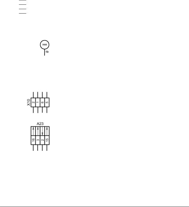
-The description provided inside the circle (e.g. “H44”) defines the connection.
-Numbers next to the circle (e.g. “1b”) describe the continuation of the cabling in accordance with the circuit diagram numbering which can be taken from the cover sheet or from the footer.
Designations
-Connectors (e.g. „X10”, pin 2– 1– 6– 5).
Each chapter lists the respective connectors and their pin assignment in the individual connection tables.
-Modules (e.g. “A23”)
The arrows identify the functional inputs and outputs according to the assignment table provided in chapter ZE.
Wiring loom A |
- Position of components according to wiring looms |

Electric System |
|
|
Rollant 240/250 |
TIC |
||||
|
|
- A 1 .. Z 99 |
- Component designation according to CLAAS standards catalogue |
|||||
|
|
|
|
|
A - Terminal / Module |
|
||
|
|
|
|
|
B - Sensor |
|
|
|
|
|
|
|
|
E - Lighting |
|
|
|
|
|
|
|
|
F - Fuse |
|
|
|
|
|
|
|
|
G - Voltage Source |
|
||
|
|
|
|
|
H - Signalling Device / Lamp |
|
||
|
|
|
|
|
K - Relay |
|
|
|
|
|
|
|
|
M - Electric motor |
|
||
|
|
|
|
|
P - Gauge |
|
|
|
|
|
|
|
|
R - Potentiometer / Resistor |
|
||
|
|
|
|
|
S - Switches – Cab Operation |
|
||
|
|
|
|
|
T - Switches – Terminal Operation |
|
||
|
|
|
|
|
U - Switches – External Operation |
|
||
|
|
|
|
|
V - Electronic Component |
|
||
|
|
|
|
|
W - Antenna |
|
|
|
|
|
|
|
|
X - Connector |
|
|
|
|
|
|
|
|
Y - Solenoid Coil |
|
||
|
|
|
|
|
Z - Actual Value Function Switch |
|
||
|
|
|
|
|
Wire colours / Wire cross-sections |
|
||
|
|
|
|
|
- Indication of cross-section (mm²) and colour |
|
||
|
Connector |
mm² |
Colour |
|
|
|||
|
|
|
|
|
|
|||
|
XT1 – 1 |
1.5 |
bk |
|
rd – red |
|
|
|
|
XT1 – 2 |
1.5 |
br |
|
|
|
|
|
|
|
bk – black |
|
|
|
|||
|
XT1 – 4 |
1.5 |
bk-rd |
|
br – brown |
|
|
|
|
XT1 – 5 |
1.5 |
br-rd |
|
wt – white |
|
|
|
|
|
|
|
|
bl – blue |
|
|
|
|
|
|
|
|
gr – grey |
|
|
|
|
XT2 – 1 |
1.5 |
bk |
|
|
|
|
|
|
|
ye – yellow |
|
|
|
|||
|
XT2 – 2 |
1.5 |
bk-rd |
|
|
|
|
|
|
|
gn– green |
|
|
|
|||
|
XT2 – 3 |
1.5 |
br-rd |
|
|
|
|
|
|
|
pi – pink |
|
|
|
|||
|
XT2 – 15 |
1.5 |
br |
|
or – orange |
|
|
|
|
|
|
|
|
vi – violet |
|
|
|
|
|
|
|
|
- Meaning of wire colours |
|
||
|
|
|
|
|
bk |
- |
+30 Power supply from tractor [12V power] |
|
|
|
|
|
|
br |
- |
-31 Power supply from tractor [0V power] |
|
|
|
|
|
|
bk-rd |
- |
+15 switched via CCT [12V electronics] |
|
|
|
|
|
|
br-rd |
- |
-31 via CCT [0V electronic system] |
|
|
|
|
|
|
bk-wt |
- |
+30 switched via K90 (polarity reversal |
|
|
|
|
|
|
|
|
protection) [12V power] |
|

TIC |
Rollant 240/250 |
Electric System |
|
|
|
Contents
Central terminal compartment....................................................................................... |
9 |
|
|
Rollant 240 Standard ........................................................................................................... |
9 |
|
Rollant 250 Standard ........................................................................................................... |
9 |
Central terminal compartment..................................................................................... |
13 |
|
|
Rollant 250 Comfort ........................................................................................................... |
13 |
Central terminal compartment..................................................................................... |
17 |
|
|
UNIWRAP .......................................................................................................................... |
17 |
Pin assignment in modules ......................................................................................... |
21 |
|
|
Rollant 240......................................................................................................................... |
21 |
|
Rollant 250......................................................................................................................... |
21 |
|
UNIWRAP .......................................................................................................................... |
21 |
1a |
Main power supply............................................................................................... |
27 |
|
Rollant 240 Standard ......................................................................................................... |
27 |
|
Rollant 250 Standard ......................................................................................................... |
27 |
1b |
Main power supply............................................................................................... |
31 |
|
Rollant 250 Comfort ........................................................................................................... |
31 |
1c |
Main power supply............................................................................................... |
35 |
|
Rollant 250 Comfort for UNIWRAP .................................................................................... |
35 |
1d |
Main power supply............................................................................................... |
41 |
|
UNIWRAP .......................................................................................................................... |
41 |
4a |
Circulation shut-off valve .................................................................................... |
45 |
|
Rollant 250 Comfort ........................................................................................................... |
45 |
4b |
Circulation shut-off valve .................................................................................... |
49 |
|
Rollant 250 Comfort for UNIWRAP .................................................................................... |
49 |
4c |
Circulation shut-off valve .................................................................................... |
53 |
|
UNIWRAP .......................................................................................................................... |
53 |
5a |
Terminal ................................................................................................................ |
57 |
|
Rollant 250 Comfort ........................................................................................................... |
57 |
5b |
Terminal ................................................................................................................ |
61 |
|
Rollant 250 Comfort for UNIWRAP .................................................................................... |
61 |
6a CAN bus, module power supply ......................................................................... |
65 |
|
|
Rollant 240 Standard ......................................................................................................... |
65 |
|
Rollant 250 Standard ......................................................................................................... |
65 |
6b CAN bus, module power supply ......................................................................... |
69 |
|
|
Rollant 250 Comfort ........................................................................................................... |
69 |

Electric System |
Rollant 240/250 |
TIC |
|
6c |
CAN bus, module power supply......................................................................... |
75 |
|
|
Rollant 250 Comfort for UNIWRAP |
.................................................................................... |
75 |
6d CAN bus, module power supply......................................................................... |
81 |
||
|
UNIWRAP up to serial no. 72900130................................................................................. |
81 |
|
6e |
CAN bus, module power supply......................................................................... |
85 |
|
|
UNIWRAP from serial no. 72900131.................................................................................. |
85 |
|
7a |
Rotocut................................................................................................................. |
|
89 |
|
Rollant 240 Standard.......................................................................................................... |
|
89 |
|
Rollant 250 Standard.......................................................................................................... |
|
89 |
7b |
Rotocut................................................................................................................. |
|
93 |
|
Rollant 250 Comfort ........................................................................................................... |
|
93 |
|
Rollant 250 Comfort for UNIWRAP |
.................................................................................... |
93 |
11a |
Wrapping release................................................................................................. |
|
99 |
|
Rollant 240 Standard.......................................................................................................... |
|
99 |
|
Rollant 250 Standard.......................................................................................................... |
|
99 |
11b |
Wrapping release............................................................................................... |
|
105 |
|
Rollant 250 Comfort ......................................................................................................... |
|
105 |
|
Rollant 250 Comfort for UNIWRAP |
.................................................................................. |
105 |
12a |
Open / close tailgate.......................................................................................... |
|
115 |
|
Rollant 250 Comfort ......................................................................................................... |
|
115 |
|
Rollant 250 Comfort for UNIWRAP |
.................................................................................. |
115 |
19a |
Load / unload bale ............................................................................................. |
|
119 |
|
UNIWRAP ........................................................................................................................ |
|
119 |
20a |
Raise / lower pick-up......................................................................................... |
|
127 |
|
Rollant 250 Comfort ......................................................................................................... |
|
127 |
|
Rollant 250 Comfort for UNIWRAP |
.................................................................................. |
127 |
21a |
Wrapping arm rotation ...................................................................................... |
|
131 |
|
UNIWRAP ........................................................................................................................ |
|
131 |
22a |
Open / close film cutter, film break monitoring .............................................. |
139 |
|
|
UNIWRAP ........................................................................................................................ |
|
139 |
32a |
Taillight, side light ............................................................................................. |
|
147 |
40a |
Additional sockets............................................................................................. |
|
151 |
|
Rollant 250 Comfort ......................................................................................................... |
|
151 |
40b |
Additional sockets............................................................................................. |
|
155 |
|
Rollant 250 Comfort for UNIWRAP |
.................................................................................. |
155 |
40c |
Additional sockets............................................................................................. |
|
161 |
|
UNIWRAP up to serial no. 130......................................................................................... |
|
161 |

TIC |
Rollant 240/250 |
Electric System |
Wiring loom A – part 1 ............................................................................................... |
|
166 |
- Rollant 250 Standard ..................................................................................................... |
|
166 |
Wiring loom A – part 2 ............................................................................................... |
|
168 |
- Rollant 250 Standard ..................................................................................................... |
|
168 |
Wiring loom B – part 1 ............................................................................................... |
|
170 |
- Rollant 250 Comfort....................................................................................................... |
|
170 |
- Rollant 250 Comfort for UNIWRAP................................................................................ |
170 |
|
Wiring loom B – part 2 ............................................................................................... |
|
172 |
- Rollant 250 Comfort....................................................................................................... |
|
172 |
- Rollant 250 Comfort for UNIWRAP................................................................................ |
172 |
|
Wiring loom B – part 3 ............................................................................................... |
|
174 |
- Rollant 250 Comfort....................................................................................................... |
|
174 |
- Rollant 250 Comfort for UNIWRAP................................................................................ |
174 |
|
Wiring loom C ............................................................................................................. |
|
176 |
- Rollant 250 Comfort....................................................................................................... |
|
176 |
- Rollant 250 Comfort for UNIWRAP................................................................................ |
176 |
|
Wiring loom D ............................................................................................................. |
|
178 |
- Rollant 250 Comfort for UNIWRAP................................................................................ |
178 |
|
Wiring loom K ............................................................................................................. |
|
180 |
- UNIWRAP...................................................................................................................... |
|
180 |
Wiring loom L.............................................................................................................. |
|
182 |
- UNIWRAP...................................................................................................................... |
|
182 |
Wiring loom M............................................................................................................. |
|
184 |
- UNIWRAP...................................................................................................................... |
|
184 |
Index ............................................................................................................................ |
|
187 |

Electric System |
Rollant 240/250 |
TIC |
Central terminal compartment
-Rollant 240 Standard
-Rollant 250 Standard
Electric System |
Rollant 240/250 |
TIC |
Central terminal compartment Rollant 240/250 Standard
10 |
rol-e-ze |
11/04 |
TIC |
|
Rollant 240/250 |
Electric System |
|
|
|
|
|
|
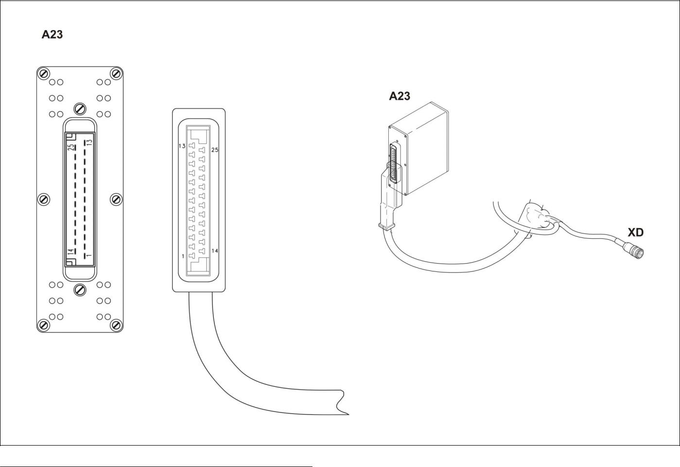
Key to diagram: |
A23 |
ROLLANT 240/250 Standard |
|
|
|
|
module............................................. |
Wiring loom A – part 2 |
|
|
XD |
CAN bus socket (7 pin) ................... |
Wiring loom A – part 2 |
|
11/04 |
rol-e-ze |
11 |

Electric System |
Rollant 240/250 |
TIC |
12 |
rol-e-ze |
11/04 |
Central terminal compartment
- Rollant 250 Comfort
Electric System |
Rollant 240/250 |
TIC |
Central terminal compartment Rollant 250 Comfort
14 |
rol-e-ze |
11/04 |

TIC |
|
Rollant 240/250 |
Electric System |
|
|
|
|
|
|
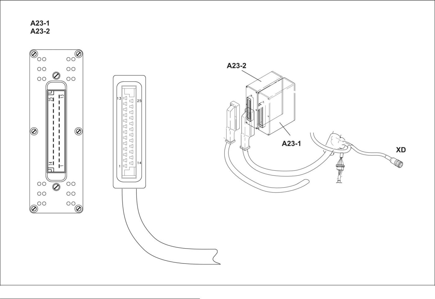
Key to diagram: |
A23-1 |
ROLLANT module 1 ........................ |
Wiring loom B – part 2 |
|
|
A23-2 |
ROLLANT module 2 ........................ |
Wiring loom B – part 2 |
|
|
XD |
CAN bus connector (7 pin) |
|
|
|
|
terminal............................................ |
Wiring loom B – part 2 |
|
11/04 |
rol-e-ze |
15 |

Electric System |
Rollant 240/250 |
TIC |
16 |
rol-e-ze |
11/04 |
Central terminal compartment
- UNIWRAP

Electric System |
UNIWRAP |
TIC |
Central terminal compartment UNIWRAP
18 |
rol-e-ze |
11/04 |

TIC |
|
|
|
|
|
UNIWRAP |
Electric System |
|
|
|
|
|
|
|
|
|
|
Key to diagram: |
|
A22 |
UNIWRAP bale wrapper module |
|
||||
|
|
|
|
|
A30-1 |
Bale wrapper terminal |
|
|
|
|
|
|
|
F 3 |
Fuse (15 Amperes) |
|
|
|
|
|
|
|
RS 232 |
Data link |
|
|
|
|
|
|
|
XD2 |
CAN bus socket (7 pin) |
|
|
|
|
|
|
|
X-X |
Socket |
|
|
|
|
|
|
|
XT-1 |
Terminal connector |
|
|
|
|
|
|
|
X30a |
UNIWRAP link connector |
|
|
|
|
|
|
|
X30b |
Blind connector (on Rollant balers without UNIWRAP) |
||
|
|
|
|
|
X34 |
Hydraulic system connector |
|
|
|
|
|
|
|
X35 |
Sensor system connector |
|
|
|
|
|
|
|
X36 |
Hydraulic system connector |
|
|
|
|
|
|
|
X37 |
Sensor system connector |
|
|
|
|
|
|
|
|
|
|
|
|
Connector |
|
mm² |
Colour |
|
|
|
|
|
X-X |
E |
|
0.5 |
rd |
|
|
|
|
X-X |
L |
|
0.5 |
bk |
|
|
|
|
X-X |
H |
|
0.5 |
gn-ye |
|
|
|
|
X-X |
- |
|
0.5 |
vi |
|
|
|
|
X-X |
- |
|
0.5 |
br-rd |
|
|
|
|
X-X |
+ |
|
0.5 |
bk-rd |
|
|
|
11/04 |
rol-e-ze |
19 |
|
Electric System |
UNIWRAP |
TIC |
|
|
|
|
|
|
|
|
|
|
|
|
|
|
|
|
20 |
rol-e-ze |
11/04 |
Pin assignment in modules
Rollant 240
Rollant 250
UNIWRAP

Electric System |
Rollant 240/250 |
|
|
TIC |
||
Module A23 Rollant 240/250 Standard |
|
|
|
|
|
|
|
|
|
|
|
|
|
Pin |
Function |
|
Component |
Measuring |
Direction |
Circuit |
|
|
|
|
variable |
|
diagram no. |
1 |
ROTOCUT knives ON solenoid coil |
|
Y55 |
12 V |
Output |
7a |
2 |
Electronics earth |
|
32 |
Earth |
Input |
6a |
3 |
CAN high |
|
- |
- |
- |
6a |
4 |
Not used |
|
- |
- |
- |
- |
5 |
Wrapping release switch (manual) |
|
S77 |
Earth |
Input |
11a |
6 |
Not used |
|
- |
- |
- |
- |
7 |
Not used |
|
- |
- |
- |
- |
8 |
Not used |
|
- |
- |
- |
- |
9 |
Not used |
|
- |
- |
- |
- |
10 |
Cam track switch |
|
Z35 |
12 V |
Input |
11a |
11 |
Not used |
|
- |
- |
- |
- |
12 |
Twine/net coupling solenoid coil |
|
Y39 |
12 V |
Output |
11a |
13 |
Buzzer |
|
H44 |
12 V |
Output |
11a |
14 |
ROTOCUT knives OFF |
|
Y54 |
12 V |
Output |
7a |
15 |
Electronics plus |
|
15 |
12 V |
Input |
6a |
16 |
CAN low |
|
- |
- |
- |
6a |
17 |
No function |
|
- |
- |
- |
- |
18 |
Wrapping delay switch (manual) |
|
S76 |
Earth |
Input |
11a |
19 |
Wrapping type selector switch |
|
S74 |
Earth |
Input |
11a |
20 |
Power plus |
|
K 90 / 87 |
12 V |
Input |
7a, 11a |
|
(protected against rev. polarity) |
|
|
|
|
|
21 |
Tailgate closed switch |
|
Z16 |
12 V |
Input |
11a |
22 |
Bale ejector switch |
|
Z6 |
12 V |
Input |
11a |
23 |
Main switch ON / OFF - Rotocut ON / OFF |
S75 |
12 V |
Input |
7a |
|
24 |
Not used |
|
- |
- |
- |
- |
25 |
Operating light |
|
H3 |
12 V |
Output |
11a |
22 |
rol-e-ze |
11/04 |

TIC |
Rollant 240/250 |
|
Electric System |
||
|
|
|
|
|
|
Module A23 –1 Rollant 250 Comfort and Rollant 250 Comfort for Uniwrap |
|
|
|||
|
|
|
|
|
|
Pin |
Function |
Component |
Measuring |
Direction |
Circuit |
|
|
|
variable |
|
diagram no. |
1 |
Twine coupling |
Y38 |
12 V |
Output |
11b |
2 |
Electronics earth |
32 |
Earth |
Input |
6b, 6c |
3 |
CAN high |
- |
- |
- |
6b, 6c |
4 |
Amplifier (net cutter motor) |
V16 |
5 V |
Output |
11b |
5 |
Drive speed sensor |
B9 |
highlow (-) |
Input |
11b |
6 |
Left twine ball speed sensor |
B13 |
highlow (-) |
Input |
11b |
7 |
Not used |
- |
- |
- |
- |
8 |
Not used |
- |
- |
- |
- |
9 |
Tailgate open switch |
Z17 |
12 V |
Input |
11b |
10 |
Cam track switch |
Z35 |
12 V |
Input |
11b |
11 |
Not used |
- |
- |
- |
- |
12 |
Tailgate open solenoid coil |
Y27 |
12 V |
Output |
12a |
13 |
Tailgate close solenoid coil |
Y28 |
12 V |
Output |
12a |
14 |
Net coupling solenoid coil |
Y41 |
12 V |
Output |
11b |
15 |
Electronics plus |
15 |
12 V |
Input |
6b, 6c |
16 |
CAN low |
- |
- |
- |
6b, 6c |
17 |
Buzzer |
H44 |
5 V |
Output |
5a, 5b |
18 |
Right twine ball speed sensor |
B14 |
highlow (-) |
Input |
11b |
19 |
Net roll speed sensor |
B22 |
highlow (-) |
Input |
11b |
20 |
Power plus (protected ag. rev. polarity) |
K 90 / 87 |
12 V |
Input |
4a, 4b, 11b, |
|
|
|
|
|
12a |
21 |
Tailgate closed switch |
Z16 |
12 V |
Input |
11b |
22 |
Bale ejector switch |
Z6 |
12 V |
Input |
11b |
23 |
No function |
- |
- |
- |
40a, 40b |
24 |
Not used |
- |
- |
- |
- |
25 |
Circulation shut-off valve solenoid coil |
Y77 / Y77-2 |
12 V |
Output |
4a, 4b |
Module A23 – 2 Rollant 250 Comfort and Rollant 250 Comfort for Uniwrap |
|
|
|||
|
|
|
|
|
|
Pin |
Function |
Component |
Measuring |
Direction |
Circuit |
|
|
|
variable |
|
diagram no. |
1 |
Pick-up lower solenoid coil |
Y49 |
12 V |
Output |
20a |
2 |
Electronics earth |
32 |
Earth |
Input |
6b, 6c |
3 |
CAN high |
- |
- |
- |
6b, 6c |
4 |
No function |
- |
- |
- |
40a, 40b |
5 |
No function |
- |
- |
- |
40a, 40b |
6 |
Not used |
- |
- |
- |
- |
7 |
Not used |
- |
- |
- |
- |
8 |
Not used |
- |
- |
- |
- |
9 |
No function |
- |
- |
- |
40a, 40b |
10 |
No function |
- |
- |
- |
40a, 40b |
11 |
Electronics plus |
15 |
12 V |
Input |
6b, 6c |
12 |
Rotor reverse solenoid coil |
Y56 |
12 V |
Output |
7b |
|
(extend cylinder) |
|
|
|
|
13 |
Rotor reverse solenoid coil |
Y57 |
12 V |
Output |
7b |
|
(retract cylinder) |
|
|
|
|
14 |
Pick-up raise solenoid coil |
Y48 |
12 V |
Output |
20a |
15 |
Electronics plus |
15 |
12 V |
Input |
6b, 6c |
16 |
CAN low |
- |
- |
- |
6b, 6c |
17 |
No function |
- |
- |
- |
40a, 40b |
18 |
Not used |
- |
- |
- |
- |
19 |
Not used |
- |
- |
- |
- |
20 |
Power plus (protected ag. rev. polarity) |
K 90 / 87 |
12 V |
Input |
7b, 20a |
21 |
Reverser switch |
Z48 |
12 V |
Input |
7b |
22 |
No function |
- |
- |
- |
40a, 40b |
23 |
Not used |
- |
- |
- |
- |
24 |
Not used |
- |
- |
- |
- |
25 |
Relay K93 (ROTOCUT knives ON/OFF) |
K93 |
12 V |
Output |
7b |
11/04 |
rol-e-ze |
23 |

Electric System |
Rollant 240/250 |
TIC |
Module A22 – Uniwrap bale wrapper (Pin assignment on connector X100)
Pin |
Function |
Component |
Measuring |
Direction |
Circuit |
|
|
|
variable |
|
diagram no. |
1 |
Not used |
- |
- |
- |
- |
2 |
Rotate wrapping arm forward solenoid coil |
Y133 |
12 V PWM |
Output |
21a |
3 |
Not used |
- |
- |
- |
- |
4 |
Wrapping arm basic position sensor |
B106 |
highlow (-) |
Input |
21a |
5 |
Film break monitoring receiver |
V12 |
highlow (-) |
Input |
22a |
6 |
Not used |
- |
- |
- |
- |
7 |
Not used |
- |
- |
- |
- |
8 |
Rollant circulation shut-off valve solenoid |
Y77-1 |
12 V |
Output |
4c |
|
coil |
|
|
|
|
9 |
Rotate wrapping arm backward solenoid |
Y134 |
12 V |
Output |
21a |
|
coil |
|
|
|
|
10 |
Lower tipping cradle solenoid coil |
Y135 |
12 V |
Output |
19a |
11 |
No function |
- |
- |
- |
40c |
12 |
Raise tipping cradle solenoid coil |
Y136 |
12 V |
Output |
19a |
13 |
Close film cutters solenoid coil |
Y140 |
12 V |
Output |
22a |
14 |
Raise wrapping table |
Y138 |
12 V |
Output |
19a |
15 |
Not used |
- |
- |
- |
- |
16 |
Not used |
- |
- |
- |
- |
17 |
Not used |
- |
- |
- |
- |
18 |
Not used |
- |
- |
- |
- |
19 |
Not used |
- |
- |
- |
- |
20 |
Not used |
- |
- |
- |
- |
21 |
Bale on wrapping table switch |
Z92 |
Earth |
Input |
19a |
22 |
Safety bracket switch |
Z91/91-2 |
Earth |
Input |
21a |
23 |
Wrapping arm rotations sensor |
B107 |
highlow (-) |
Input |
21a |
24 |
Not used |
- |
- |
- |
- |
25 |
Not used |
- |
- |
- |
- |
26 |
Not used |
- |
- |
- |
- |
27 |
Not used |
- |
- |
- |
- |
28 |
Lower wrapping table solenoid coil |
Y137 |
12 V |
Output |
19a, 21a, 22a |
29 |
0 Volt power (earth) |
A22 |
0 V |
Output |
19a, 21a, 22a |
30 |
Not used |
- |
- |
- |
- |
31 |
12 V (sensor power supply) |
A22 |
12 V |
Output |
19a |
32 |
Not used |
- |
- |
- |
- |
33 |
Not used |
- |
- |
- |
- |
34 |
Wrapping table at top switch |
B105 |
highlow (-) |
Input |
19a |
35 |
Not used |
- |
- |
- |
- |
36 |
Bale in tipping cradle sensor |
B102 |
highlow (-) |
Input |
19a |
37 |
Tipping cradle at bottom sensor |
B103 |
highlow (-) |
Input |
19a |
38 |
0 V (sensor power supply) |
A22 |
0 V |
Output |
19a, 21a, 22a |
39 |
Not used |
- |
- |
- |
- |
40 |
Not used |
- |
- |
- |
- |
41 |
Open film cutters |
Y139 |
12 V |
Output |
22a |
42 |
Not used |
- |
- |
- |
- |
24 |
rol-e-ze |
11/04 |

TIC |
Rollant 240/250 |
Electric System |
|
|
|
Circuit diagram allocation of fuses and relays
25 A On tractor side (not shown) / protects + 30
K90 1a, 1b, 1c
K93 7b
V16 11b
11/04 |
rol-e-ze |
25 |

Electric System |
Rollant 240/250 |
TIC |
26 |
rol-e-ze |
11/04 |
1a
Main power supply
Rollant 240 Standard
Rollant 250 Standard
Electric System |
Rollant 240/250 |
TIC |
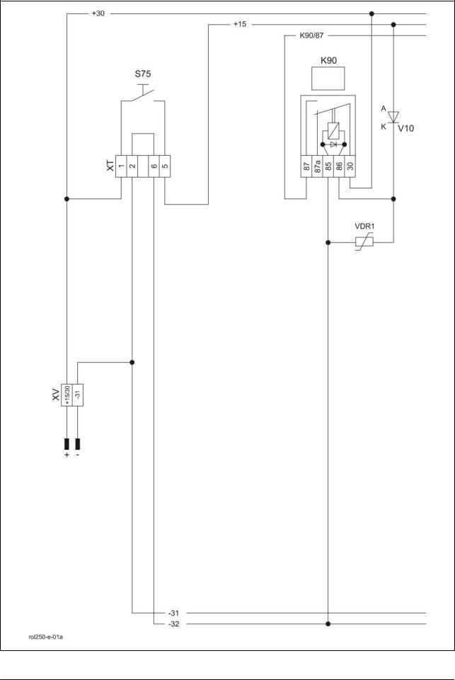
01a - Main power supply |
Rollant 240/250 Standard |
|
Key to diagram: |
K90 |
Power supply relay |
|
|
|
(protected against reverse polarity).... |
Wiring loom A-part 2 |
|
S75 |
Main switch......................................... |
Wiring loom A-part 1 |
|
V10 |
Reverse polarity protection Diode ..... |
Wiring loom A-part 2 |
|
VDR1 |
Varistor ............................................... |
Wiring loom A-part 2 |
|
XT |
Terminal connector ............................ |
Wiring loom A-part 1 |
|
XV |
Power supply connector..................... |
Wiring loom A-part 1 |
Measured value table: |
Item |
Component |
Measured value |
Note |
|
K90 |
Remote control relay |
75±10 Ω |
(Pin 86/1 – 85/2) |
|
|
20 A |
|
(Pin 87a/4 – 30/3) |
|
|
30 A |
|
(Pin 87/5 – 30/3) |
28 |
rol-e-ze |
11/04 |

TIC |
Rollant 240/250 |
Electric System |
|
|
|
|
|
Description of function: |
|
|
|
Main power supply |
Power supply from the tractor to the baler is via connector XV. On the |
||
|
tractor, this prower supply should be protected by a fuse of 25 A max. |
||
Potential + 15 |
This is switched by the main switch T 12 on the control box |
||
|
(electronics +). |
|
|
Potential K 90 / 87 |
Potential K 90/ 87 is a power plus protected against reverse polarity by |
||
|
diode V10. |
|
|
Overvoltage protection |
VDR1 becomes conducting when overvoltage occurs. This smooths the |
||
|
voltage peaks in the electronics circuit (+15 / -32). |
|
|
11/04 |
rol-e-01a |
29 |
Electric System |
Rollant 240/250 |
TIC |
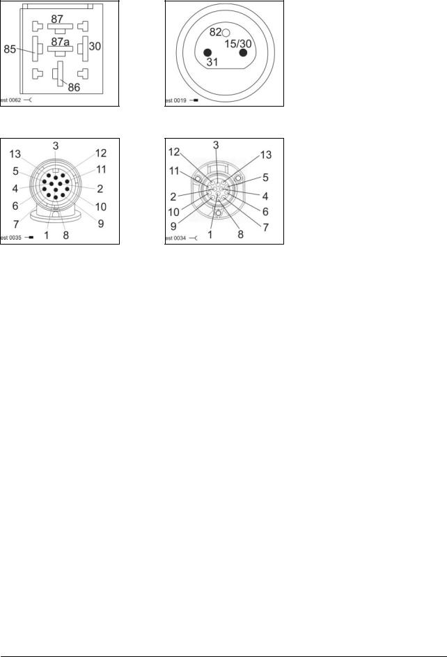
Connector pin definition
Socket K90
Connector XT
Connector XV
Socket XT
Connector |
mm² |
Colour |
K90/30 |
2.5 |
bk |
K90/85 |
1.0 |
br-rd |
K90/86 |
0.75 |
bk-rd |
K90/87 |
2.5 |
bk-wt |
|
|
|
XT1 – 1 |
1.5 |
bk |
XT1 – 2 |
1.5 |
br |
XT1 – 5 |
1.5 |
bk-rd |
XT1 – 6 |
1.5 |
br-rd |
|
|
|
XT2 – 1 |
1.5 |
bk |
XT2 – 2 |
1.5 |
br |
XT2 – 5 |
1.5 |
bk-rd |
XT2 – 6 |
1.5 |
br-rd |
Connector |
mm² |
Colour |
XV - 15/30 |
2.5 |
bk |
XV - 31 |
2.5 |
br |
30 |
rol-e-ze |
11/04 |
Loading...