


 Loading...
VARIANT 260/280
Technical Systems
Hydraulic System

Hydraulic System |
VARIANT 260/280 |
TIC |
2 |
var-h |
11/04 |

TIC |
VARIANT 260/280 |
Hydraulic System |
Hydraulic system
Contents
Chapter 1 Overall hydraulic system circuit diagram |
.............................5 |
Chapter 2 Function ................................................................................. |
15 |
Chapter 3 Valve components................................................................. |
29 |
Index......................................................................................................... |
57 |
11/04 |
var-h |
3 |

Hydraulic System |
VARIANT 260/280 |
TIC |
4 |
var-h |
11/04 |

TIC |
VARIANT 260/280 |
Hydraulic System |
Chapter 1 Overall hydraulic system circuit diagram
1.1 Circuit diagram – without active hydraulic system............................. |
6 |
1.2 Circuit diagram – with active hydraulic system, |
|
with integrated pressure holding valve (754) up to serial no. … ..... |
10 |
1.3 Circuit diagram – with active hydraulic system, |
|
without integrated pressure holding valve (754) from serial no. ..... |
12 |
11/04 |
var-h |
5 |
Hydraulic System |
VARIANT 260/280 |
TIC |
1.1Circuit diagram – without active hydraulic system
6 |
var-h |
11/04 |

TIC |
VARIANT 260/280 |
Hydraulic System |
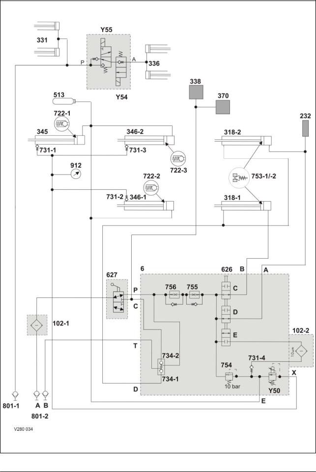
Key to diagram:
6Valve block
102-1 Filter (option)
When factory-mounted, filter (102-2) is not provided - in this case, a hydraulic loop line is installed here. In case of retrofits, filter (102-2) remains in place.
102-2 Filter (series equipment)
232Lubricating oil pump
is actuated when building up pressure for opening the tailgate.
318-1 Left side tailgate hydraulic cylinder
318-2 Right side tailgate hydraulic cylinder
331Pick-up raise/lower hydraulic cylinders 2 pieces, spring-loaded
336 Knife support On/Off hydraulic cylinder
338 Rotor cut-out clutch
345 Top tensioning arm hydraulic cylinder
346-1 Bottom left tensioning arm hydraulic cylinder
346-2 Bottom right tensioning arm hydraulic cylinder
370Drive clutch for roller no. 3. When subject to pressure, the clutch opens so that roller no. 3 does not drive the belts (when opening the tailgate).
513Hydraulic accumulator pressurised to 2 bar
626-C Shut-off tap
for left-side tailgate cylinder. Is combined with 626-D and 626-E.
626-D Shut-off tap
for right-side tailgate cylinder. Is combined with 626-C and 626-E.
626-E Shut-off tap
for belt tensioner cylinder. Is combined with 626-B and 626-C.
-blocked when 626-C and 626-D are open.
-open when 626-C and 626-D are blocked.
627Shut-off tap
In the initial position (see circuit diagram):
-the oil supply to valve block (6), (input P) is ensured.
-the oil supply to the rotor cut-out clutch (338) is shut off.
When actuated:
-the oil supply to the valve block (6), (input P), is shut off
-the oil supply to the rotor cut-out clutch is provided.
11/04 |
var-h |
7 |

Hydraulic System |
VARIANT 260/280 |
TIC |
722-1 Anti-cavitation valve opening pressure 3.6 bar
722-2 Anti-cavitation valve opening pressure 3.6 bar
722-3 Anti-cavitation valve opening pressure 3.6 bar
731-1 Non-return valve
731-2 Non-return valve
731-3 Non-return valve
731-4 Non-return valve
shuts off the pre-pressurizing circuit against the filter circuit.
734-1 Non-return valves lock-up valve unit
734-2 shut off the tailgate cylinders (318), the rotor cut-out clutch (338) and the drive clutch (370).
753-1 Pressure relief valve
753-2 limits the pressure in the rod spaces to 250 bar.
754Pressure relief valve
maintains the pressure in the tensioning arm circuit at 10 bar.
755Flow controller
controls the volume flow for opening the tailgate to 50 l/min. The non-return valve does actually not exist – here it serves merely for better understanding of the circuit diagram.
756Flow controller
controls the volume flow for closing the tailgate to 18 l/min. The non-return valve does actually not exist – here it serves merely for better understanding of the circuit diagram.
801-1 Quick release coupling
single-acting control unit. Oil supply for knife support and pick-up.
801-2 Quick release couplings
double-acting control unit Open / close tailgate oil supply.
912 Baling pressure gauge
Y50 Baling pressure build-up solenoid valve
-limits the pressure in the tensioning arm circuit and thus controls the baling pressure.
-is controlled by the electronic box (the desired baling pressure is set by a potentiometer).
-when the power supply fails, the highest baling pressure is reached.
Y54 ROTOCUT knives OUT solenoid valve
Y55 ROTOCUT knives IN solenoid valve
8 |
var-h |
11/04 |

TIC |
VARIANT 260/280 |
Hydraulic System |
Notes:
11/04 |
var-h |
9 |

Hydraulic System |
VARIANT 260/280 |
TIC |
1.2Circuit diagram – with active hydraulic system, with integrated pressure holding valve (754) up to serial no. …
10 |
var-h |
11/04 |
TIC |
VARIANT 260/280 |
Hydraulic System |
|
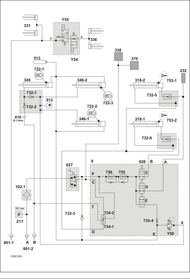
Key to diagram: |
|
|
|
6 |
Valve block |
|
|
102-1 |
Filter (option) |
|
|
102-2 |
Filter |
|
|
232 |
Lubricating oil pump |
|
|
318-1 |
Tailgate left hydraulic cylinder |
|
|
318-2 |
Tailgate right hydraulic cylinder |
|
|
331 |
Pick-up hydraulic cylinder |
|
|
336 |
Knife support hydraulic cylinder |
|
|
338 |
Rotor cut-out clutch |
|
|
345 |
Top right tensioning arm hydraulic cylinder |
|
|
346-1 |
Bottom left tensioning arm hydraulic cylinder |
|
|
346-2 |
Bottom right tensioning arm hydraulic cylinder |
|
|
370 |
Roller 3 drive clutch |
|
|
410 |
Orifice plate diam. 1.5 mm (for oil flow limiting) |
|
|
513 |
Hydraulic accumulator (pressurised to 2 bar) |
|
|
626-C |
Shut-off tap |
|
|
626-D |
Shut-off tap |
|
|
626-E |
Shut-off tap |
|
|
627 |
Shut-off tap |
|
|
722-1 |
Anti-cavitation valve (open pressure 3.6 bar) |
|
|
722-2 |
Anti-cavitation valve (open pressure 3.6 bar) |
|
|
722-3 |
Anti-cavitation valve (open pressure 3.6 bar) |
|
|
732-1 |
Non-return valve |
|
|
732-2 |
Non-return valve |
|
|
732-3 |
Non-return valve |
|
|
732-4 |
Non-return valve |
|
|
732-5 |
Non-return valve |
|
|
732-6 |
Non-return valve |
|
|
734-1 |
Lock-up valve unit (non-return valve) |
|
|
734-2 |
Lock-up valve unit (non-return valve) |
|
|
753-1, -2 Pressure relief valve 250 bar
754Pressure holding valve is blocked = no function
755Flow controller
756Flow controller
801-1 Quick release coupling
(single-acting additional control unit on tractor) 801-2 Quick release couplings
(double-acting additional control unit on tractor) 912 Baling pressure gauge
Y50 Baling pressure solenoid valve
Y54 2/3 way valve, knife support out
Y55 2/3 way valve, knife support in
Z17 Pressure switch (90 bar)
11/04 |
var-h |
11 |
Hydraulic System |
VARIANT 260/280 |
TIC |
1.3Circuit diagram – with active hydraulic system, without integrated pressure holding valve (754) from serial no. ...
12 |
var-h |
11/04 |

TIC |
VARIANT 260/280 |
Hydraulic System |
|
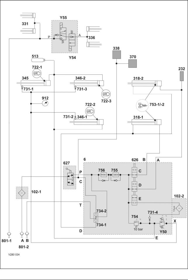
Key to diagram: |
|
|
|
6 |
Valve block |
|
|
102-1 |
Filter (option) |
|
|
102-2 |
Filter |
|
|
232 |
Lubricating oil pump |
|
|
318-1 |
Tailgate left hydraulic cylinder |
|
|
318-2 |
Tailgate right hydraulic cylinder |
|
|
331 |
Pick-up hydraulic cylinder |
|
|
336 |
Knife support hydraulic cylinder |
|
|
338 |
Rotor cut-out clutch |
|
|
345 |
Top right tensioning arm hydraulic cylinder |
|
|
346-1 |
Bottom left tensioning arm hydraulic cylinder |
|
|
346-2 |
Bottom right tensioning arm hydraulic cylinder |
|
|
370 |
Roller 3 drive clutch |
|
|
410 |
Orifice plate diam. 1.5 mm (for oil flow limiting) |
|
|
513 |
Hydraulic accumulator (pressurised to 2 bar) |
|
|
626-C |
Shut-off tap |
|
|
626-D |
Shut-off tap |
|
|
626-E |
Shut-off tap |
|
|
627 |
Shut-off tap |
|
|
722-1 |
Anti-cavitation valve (open pressure 3.6 bar) |
|
|
722-2 |
Anti-cavitation valve (open pressure 3.6 bar) |
|
|
722-3 |
Anti-cavitation valve (open pressure 3.6 bar) |
|
|
732-1 |
Non-return valve |
|
|
732-2 |
Non-return valve |
|
|
732-3 |
Non-return valve |
|
|
732-4 |
Non-return valve |
|
|
732-5 |
Non-return valve |
|
|
732-6 |
Non-return valve |
|
|
734-1 |
Lock-up valve unit (non-return valve) |
|
|
734-2 |
Lock-up valve unit (non-return valve) |
|
|
753-1, -2 Pressure relief valve 250 bar
755Flow controller
756Flow controller
801-1 Quick release coupling
(single-acting additional control unit on tractor) 801-2 Quick release couplings
(double-acting additional control unit on tractor) 912 Baling pressure gauge
Y50 Baling pressure solenoid valve
Y54 2/3 way valve, knife support out
Y55 2/3 way valve, knife support in
Z17 Pressure switch (90 bar)
11/04 |
var-h |
13 |

Hydraulic System |
VARIANT 260/280 |
TIC |
14 |
var-h |
11/04 |

TIC |
VARIANT 260/280 |
Hydraulic System |
|
|
|
Chapter 2
Function
2.1 Function – without active hydraulic system ..................................... |
16 |
2.2 Function – with active hydraulic system, |
|
with integrated pressure holding valve (754) up to serial no. ......... |
20 |
2.3 Function – with active hydraulic system, |
|
without integrated pressure holding valve (754) from serial no....... |
24 |
11/04 |
var-h |
15 |
Hydraulic System |
VARIANT 260/280 |
TIC |
2.1Function – without active hydraulic system
16 |
var-h |
11/04 |

TIC |
VARIANT 260/280 |
Hydraulic System |
|
|
|
|
|
Description of function: |
|
|
|
Close tailgate |
Volume flow enters the valve block (6, port T) via port (801-2 B) and flows |
||
|
to the lock-up valve unit non-return valve (734-1). The lock-up valve unit |
||
|
is opened. |
|
|
|
Pressurized oil flows into the rod spaces of hydraulic cylinders (318-1 and |
||
|
318-2) via the opened lock-up valve unit non-return valve (734-1) and |
||
|
port D. |
|
|
|
The volume flow displaced from the ram spaces of hydraulic cylinders |
||
|
(318-1 and 318-2) flows into the tank via the shut-off taps (626 C and D), |
||
|
the flow controllers (756 and 755), the shut-off tap (627) and filter (102-1). |
||
|
The flow controller controls the returning volume flow to 18 l/min., making |
||
|
the tailgate closing velocity lower than the opening velocity. |
||
Baling |
Baled material pulls the hydraulic cylinders (346-1, 346-2 and 345) to the |
||
|
outside by means of the tensioning arms. This builds up baling pressure |
||
|
in the rod spaces of these cylinders. |
|
|
|
The pressure can be read on pressure gauge (912 baling pressure). |
||
|
The baling pressure enters valve block (6) via input (X). |
||
|
The baling pressure is applied at the baling pressure build-up solenoid |
||
|
valve (Y50). |
|
|
|
When the set baling pressure has been reached, the baling pressure |
||
|
build-up solenoid valve (Y50) opens, making volume flow flow via port (E) |
||
|
into the ram sides of hydraulic cylinders (346-1, 346-2 and 345). |
||
|
The hydraulic accumulator (513) compensates the volumetric difference. |
||
Open tailgate |
Volume flow flows into valve block 6 (port P) via port (801-2 A), filter |
||
(102-1) and the rotor clutch / 2nd belt drive shut-off tap (627).
The volume flow flows via the open shut-off taps (626C and 626D) into the ram spaces of hydraulic cylinders (318-1 and 318-2), via ports (A and B). During this process, the flow rate is regulated to 50 l/min. by the flow controllers (756 and 755).
At the same time, the lubricating oil pump (232) is supplied.
Pressurized oil is tapped directly downstream of inlet (P) of valve block (6) which opens the lock-up valve unit non-return valve (734-1).
The volume flow displaced from the rod spaces of hydraulic cylinders (318-1 and 318-2) flows through the open lock-up valve unit non-return valve (734-1) and port (T) to the quick release coupling (801-2 B). Downstream of the rotor clutch / 2nd belt drive shut-off tap (627), pressurized oil flows to the rotor cut-out clutch (338) and to the drive clutch (370) for roller 3.
The clutches open so that the rotor and the drive of roller 3 are switched off while the tailgate is opened.
11/04 |
var-h |
17 |

Hydraulic System |
VARIANT 260/280 |
TIC |
Relieving the belts during maintenance work in the baling chamber
Tensioning the belts
Swinging in the knife support
-Switch on control box (baler CCT) so the baling pressure build-up solenoid valve (Y50) is energized.
-Disengage the p.t.o. shaft.
-Open the tailgate as far as necessary and secure it.
-Actuate the baling chamber service shut-off valve (626):
The shut-off taps (626 C) and (626 D) of the tailgate are now shut off and the shut-off tap (626 E) is open.
Oil flows into valve block 6 (port P) via port (801-2 A), filter (102-1) and the rotor clutch / 2nd belt drive shut-off tap (627).
Volume flow continues to flow via filter (102-2), non-return valve (731-4) and port (E) into the ram spaces of hydraulic cylinders (346-1, 346-2 and 345) through the open shut-off tap (626 E).
The cylinders extend and the belts are relieved.
The volume flow displaced from the rod spaces of hydraulic cylinders (346-1, 346-2 and 345) flows to the baling pressure build-up solenoid valve (Y50) via port (X). This valve is electronically regulated to 0 bar when the tailgate is open and oil may therefore flow freely through it.
The rod spaces and the ram spaces of the belt tensioner cylinders (346-1, 346-2 and 345) are now connected with each other.
There is the same pressure in both cylinder spaces, but since the greater force is generated on the ram surface (greater by the force of the rod surface), the cylinders extend and relieve the belts.
The baling chamber service shut-off valve still is in the "Tailgate blocked" position; now the double-acting control unit provided on the tractor is set to the "Lower" position
The hydraulic cylinders (346-1, 346-2 and 345) are retracted by springs on the left baler side.
The volume flow displaced from the ram spaces flows via port (E) and uses two different paths, depending on the pressure:
-when the pressure is above 10 bar, it flows into the tank via the pressure relief valve (754), the flow controllers (756 and 755), port
(P) and port (801-2 A).
-when the pressure is below 10 bar, the non-return valves (722-1, 722-2 and 722-3) open and provide volumetric compensation so that the tensioning arms can return to their initial position faster.
When maintenance work is finished, the tailgate is closed; during this, the belts must be driven so that they will not be squeezed.
When actuating the "Swing in knife support" button, the 2/3 way directional control valve (Y55) "ROTOCUT knives IN" is energized. Volume flow flows into the ROTOCUT knives hydraulic cylinders (336) via port (801-1) and the energized 2/3 way valve.
The ROTOCUT knives hydraulic cylinders (336) extend and swing in the knife support.
The extended ROTOCUT knives hydraulic cylinders (336) are kept in their position by the non-return valve inside the 2/3 directional control valve (Y54).
18 |
var-h |
11/04 |
Loading...