


CLAAS Lexion 700 Series - Steering
Ready Combine SmarTrax™
Installation Manual
P/N 016-5030-047 Rev. B |
09/15 |
E26478 |
Copyright 2015

|
|
Table of Contents |
Chapter 1 |
Important Safety Information................................................. |
1 |
Hydraulic Safety ........................................................................................................................ |
2 |
|
Electrical Safety ........................................................................................................................ |
2 |
|
Chapter 2 |
Introduction............................................................................. |
3 |
Preparing for Installation ........................................................................................................... |
3 |
|
Recommendations .............................................................................................................. |
4 |
|
Point of Reference ............................................................................................................... |
4 |
|
Updates ..................................................................................................................................... |
|
4 |
Kit Contents ............................................................................................................................... |
|
5 |
Chapter 3 |
Wheel Angle Sensor Installation ........................................... |
9 |
Assemble the Wheel Angle Sensor (WAS) ............................................................................... |
9 |
|
Single Steering Cylinder Models ......................................................................................... |
9 |
|
Dual Steering Cylinder Models ............................................................................................ |
9 |
|
Mount the WAS ....................................................................................................................... |
10 |
|
Single Steering Cylinder Models ....................................................................................... |
10 |
|
Dual Steering Cylinder Models .......................................................................................... |
12 |
|
Chapter 4 |
Cab Component Installation ................................................ |
15 |
Install the SmarTrax Node ....................................................................................................... |
15 |
|
Mount the SmarTrax Node ................................................................................................ |
15 |
|
Node Mounting Locations .................................................................................................. |
16 |
|
Install the Foot Switch ............................................................................................................. |
16 |
|
Install the Road Switch ............................................................................................................ |
17 |
|
Install the Node Harness ......................................................................................................... |
18 |
|
Install the Valve Harness ......................................................................................................... |
19 |
|
Install the Chassis Cable - SmarTrax-Only Systems (If Applicable) ........................................ |
24 |
|
Connect SmarTrax to an Existing SmartYield™ Pro (If Applicable) ....................................... |
24 |
|
Calibrate the SmarTrax System .............................................................................................. |
24 |
|
System Diagrams .................................................................................................................... |
25 |
|
P/N 016-5030-047 Rev. B |
i |

Table of Contents
ii CLAAS Lexion 700 Series - Steering Ready Combine SmarTrax™ Installation Manual

CHAPTER |
Important Safety |
Chapter1 |
|
1 |
Information |
|
NOTICE
Read this manual and the operation and safety instructions included with your implement and/or controller carefully before installing the SmarTrax™ system.
•Follow all safety information presented within this manual.
•If you require assistance with any portion of the installation or service of your Raven equipment, contact your local Raven dealer for support.
•Follow all safety labels affixed to the SmarTrax system components. Be sure to keep safety labels in good condition and replace any missing or damaged labels. To obtain replacements for missing or damaged safety labels, contact your local Raven dealer.
When operating the machine after installing SmarTrax, observe the following safety measures:
•Be alert and aware of surroundings.
•Do not operate SmarTrax or any agricultural equipment while under the influence of alcohol or an illegal substance.
•Remain in the operator’s position in the machine at all times when SmarTrax is engaged.
•Disable SmarTrax when exiting the operator’s seat and machine.
•Do not drive the machine with SmarTrax enabled on any public road.
•Determine and remain a safe working distance from other individuals. The operator is responsible for disabling SmarTrax when the safe working distance has diminished.
•Ensure SmarTrax is disabled prior to starting any maintenance work on SmarTrax or the machine.
 WARNING
•When starting the machine for the first time after installing SmarTrax, be sure that all persons stand clear in case a hose has not been properly tightened.
•The machine must remain stationary and switched off during SmarTrax installation or maintenance.
P/N 016-5030-047 Rev. A |
1 |

Chapter 1
 CAUTION
Hydraulic Safety
•Raven Industries recommends that appropriate protective equipment be worn at all times when working on the hydraulic system.
•Never attempt to open or work on a hydraulic system with the equipment running. Care should always be taken when opening a system that has been previously pressurized.
•When disconnecting the hydraulic hoses or purging is required, be aware that the hydraulic fluid may be extremely hot and under high pressure. Caution must be exercised.
•Any work performed on the hydraulic system must be done in accordance with the machine manufacturer’s approved maintenance instructions.
•When installing SmarTrax hydraulics or performing diagnostics, maintenance, or routine service, ensure that precautions are taken to prevent any foreign material or contaminants from being introduced into the machine’s hydraulic system. Objects or materials that are able to bypass the machine’s hydraulic filtration system will reduce performance and possibly damage the SmarTrax valve.
Electrical Safety
•Always verify that the power leads are connected to the correct polarity as marked. Reversing the power leads could cause severe damage to the equipment.
•Ensure that the power cable is the last cable to be connected.
2 CLAAS Lexion 700 Series - Steering Ready Combine SmarTrax™ Installation Manual

CHAPTER Chapter2Introduction
2
Congratulations on your purchase of the SmarTrax system! This system is designed to provide cutting-edge, hands-free steering of the machine via Global Positioning System (GPS) coordinates.
This manual applies to the following machines:
MAKE: CLAAS
MODEL: Lexion 700 Series (Steering Ready) - 730, 740, 750, 760, 770, and 780
FIGURE 1. CLAAS Lexion 760
Preparing for Installation
Before installing the SmarTrax system, park the machine where the ground is level, clean, and dry. Turn off the machine and leave it turned off for the duration of the installation process.
During the installation process, follow good safety practices. Be sure to carefully read the instructions in this manual as you complete the installation process.
P/N 016-5030-047 Rev. B |
3 |

Chapter 2
Recommendations
Raven Industries recommends the following best practices when installing or operating the SmarTrax system for the first time, at the start of the season, or when moving the SmarTrax system to another machine:
• Install the GPS antenna in the recommended location. Refer to the following table for the machine-specific antenna mounting location.
|
Antenna X Position |
Antenna Y Position |
Antenna Z Position |
|
Machine Preset |
(ground to bottom of |
|||
(left to right) |
(fore/aft offset) |
|||
|
antenna) |
|||
|
|
|
||
|
|
|
|
|
Lexion 700 Series Combines |
Centered |
17 ft. /5.181 m |
13 ft. 1 in./4.013 m |
|
|
|
|
|
• Ensure the machine’s hydraulic filters have been recently changed and there are no issues with the machine’s hydraulic system (e.g., pump issues, faulty hydraulic motors, fine metal deposits in the hydraulic hoses, etc.).
• Ensure the machine’s hydraulic system is using fresh oil and debris is flushed from the hydraulic hoses, valves, and filters.
Raven Industries recommends the following best practices when installing the SmarTrax system:
•Use part numbers to identify the parts.
•Do not remove the plastic wrap from a part until it is necessary for installation.
•Do not remove plastic caps from a part until it is necessary for installation.
Point of Reference
The instructions in this manual assume that you are standing behind the machine, looking toward the cab.
Updates
Software and manual updates are available on the Raven Applied Technology website: http://www.ravenhelp.com
4 CLAAS Lexion 700 Series - Steering Ready Combine SmarTrax™ Installation Manual

Introduction
At Raven Industries, we strive to make your experience with our products as rewarding as possible. One way to improve this experience is to provide us with feedback on this manual.
Your feedback will help shape the future of our product documentation and the overall service we provide. We appreciate the opportunity to see ourselves as our customers see us and are eager to gather ideas on how we have been helping or how we can do better.
To serve you best, please send an email with the following information to
techwriting@ravenind.com
-CLAAS Lexion 700 Series - Steering Ready Combine SmarTrax™ Installation Manual -P/N 016-5030-047 Rev. B
-Any comments or feedback (include chapter or page numbers if applicable). -Let us know how long have you been using this or other Raven products.
We will not share your email or any information you provide with anyone else. Your feedback is valued and extremely important to us.
Thank you for your time.
2
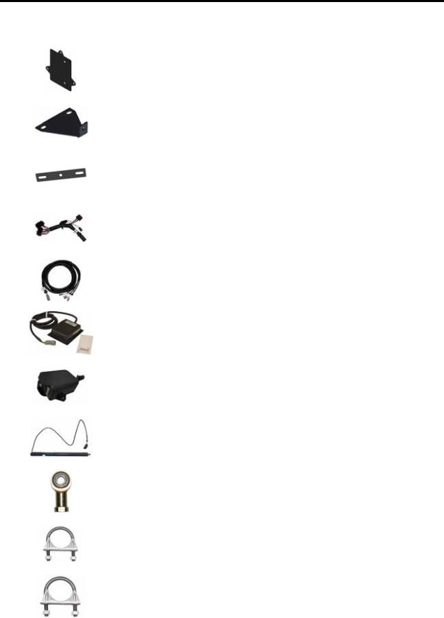
Kit Contents
This section contains a list of the components that are included in the SmarTrax kit. Before beginning the SmarTrax installation, compare the items in the kit with the components on this list. If you have questions about the kit, contact your Raven dealer.
TABLE 1. SmarTrax Installation Kit (P/N 117-5030-047)
Picture |
Item Description |
Part Number |
Qty. |
|
|
|
|
|
|
Not Pictured |
Manual - SmarTrax and SmartSteer |
016-0171-277 |
1 |
|
Calibration & Operation |
||||
|
|
|
||
|
|
|
|
|
Not Pictured |
Manual - CLAAS Lexion 700 Series |
016-5030-047 |
1 |
|
Combines SmarTrax Installation |
||||
|
|
|
||
|
|
|
|
|
|
Node - SmarTrax RTK |
063-0173-228 |
1 |
|
|
|
|
|
|
|
Bracket - WAS Mounting |
107-0172-030 |
1 |
|
|
|
|
|
P/N 016-5030-047 Rev. B |
5 |
Chapter 2
TABLE 1. SmarTrax Installation Kit (P/N 117-5030-047)
|
Picture |
Item Description |
Part Number |
Qty. |
|
|
|
|
|
|
|
|
|
Bracket - Node Mounting |
107-0172-055 |
1 |
|
|
|
|
|
|
|
|
|
Bracket - Wheel Angle Sensor Mounting |
107-0172-300 |
1 |
|
|
|
|
|
|
|
|
|
Bracket - 4”-5” Muffler Clamp Wheel Angle |
107-0172-431 |
1 |
|
|
|
Sensor Mounting |
|
||
|
|
|
|
|
|
|
|
|
|
|
|
|
|
Cable - AutoPilot-Ready Node |
115-4001-235 |
1 |
|
|
|
|
|
|
|
|
|
Cable - AutoPilot-Ready Valve |
115-4001-236 |
1 |
|
|
|
|
|
|
|
|
|
Assembly - Foot Switch |
063-0172-470 |
1 |
|
|
|
|
|
|
|
|
|
Assembly - Road Switch |
063-0173-505 |
1 |
|
|
|
|
|
|
|
|
|
Assembly - 250 mm 3-Pin Linear Wheel |
063-0181-021 |
1 |
|
|
|
Angle |
|
||
|
|
|
|
|
|
|
|
|
|
|
|
|
|
Mount - M10 Ball Linear Sensor |
103-0001-029 |
2 |
|
|
|
|
|
|
|
|
|
Clamp - 1-1/2” U-Bolt Muffler |
435-3003-030 |
1 |
|
|
|
|
|
|
|
|
|
Clamp - 2” Muffler |
435-3003-059 |
1 |
|
|
|
|
|
|
|
|
|
|
|
|
|
6 CLAAS Lexion 700 Series - Steering Ready Combine SmarTrax™ Installation Manual
|
|
|
|
Introduction |
||
|
TABLE 1. SmarTrax Installation Kit (P/N 117-5030-047) |
|
|
|
|
|
|
|
|
|
|
|
|
|
Picture |
Item Description |
Part Number |
Qty. |
|
|
|
|
|
|
|
|
|
|
|
Clamp - 3” Muffler |
435-3003-063 |
1 |
|
|
|
|
|
|
|
|
|
|
|
Clamp - 4-1/2” Muffler |
435-3003-070 |
1 |
|
|
|
|
|
|
|
2 |
|
|
|
Bolt - M10 x 1.5 x 60 mm Hex |
311-0070-025 |
2 |
||
|
|
|
|
|||
|
|
|
|
|
|
|
|
|
Spacer - 0.406” ID x 0.750” OD x 1” Long |
107-0172-038 |
2 |
|
|
|
|
|
|
|
|
|
|
|
Nut - M10 x 1.5 Pitch Jam |
312-1002-035 |
2 |
|
|
|
|
|
|
|
|
|
|
|
Nut - 5/16”-18 Nylon Insert Lock |
312-4000-059 |
4 |
|
|
|
|
|
|
|
|
|
|
|
Nut - M10 x 1.5 Pitch Nylon Insert Lock |
312-4000-208 |
2 |
|
|
|
|
|
|
|
|
|
|
|
Nut - 3/8”-16 Thin Lock |
312-4001-109 |
5 |
|
|
|
|
|
|
|
|
|
|
|
Washer - 0.344” ID x 0.688” OD x 0.065” |
313-2300-012 |
2 |
|
|
|
|
Thick |
|
|
||
|
|
|
|
|
|
|
|
|
|
|
|
|
|
|
|
Washer - 0.408” ID x 0.812” OD x 0.065 |
313-2300-014 |
2 |
|
|
|
|
Thick |
|
|
||
|
|
|
|
|
|
|
|
|
|
|
|
|
|
|
|
Tape - 3.5” Double-Sided |
332-0000-019 |
6 |
|
|
|
|
|
|
|
|
|
|
|
|
|
|
|
|
P/N 016-5030-047 Rev. B |
7 |
 Loading...