


 Loading...
LEXION 470 - 420 Montana
Technical
Systems
Electric/Hydraulic
System
Supplement
Electric System |
LEXION-Montana |
TIC |
TIC |
LEXION-Montana |
Electric System |
|
|
|
The present document exclusively describes all special electric and hydraulic functions of the LEXION Montana series.
Explanations and descriptions concerning the basic machine and the front attachments can be found in the relevant Electric System (297 550.x) and Hydraulic System
(297 549.x) documents.
D-S - |
Central terminal compartment on Montana machines 014 501.0 |
|
|
(with RIO module A50) ................................................................................. |
ZE-s-2 |
D-S - |
Central terminal compartment on Montana machines 014 501.0 |
|
|
(with HBM module A45) ............................................................................... |
ZE-s-4 |
Module A35 - Montana control unit, for Montana machines |
|
|
|
(with RIO module A50) ................................................................................. |
ZE-s-9 |
Module A35 - Montana control unit, for Montana machines |
|
|
|
(with HBM module A45) ............................................................................. |
ZE-s-10 |
Module A36 - Montana gearshift module.................................................................. |
ZE-s-11 |
|
Module A45 - Ground drive hydraulic motor brake restrictor (HBM) ......................... |
ZE-s-12 |
|
Module A50 - Montana RIO module ......................................................................... |
ZE-s-12 |
|
01s - |
Main power supply, diesel engine electric starting motor, |
|
|
for Montana machines.................................................................................... |
01s-2 |
02s - |
Starting the diesel engine, diesel engine speed adjustment |
|
|
- for Montana machines.................................................................................. |
02s-2 |
04s - |
Road travel activation, working hydraulics master valve, |
|
|
for Montana machines with module A50 (RIO)............................................... |
04s-2 |
04t - |
Road travel activation, working hydraulics master valve, |
|
|
for Montana machines with module A45 (HBM) .............................................. |
04t-2 |
05s - |
Terminal, keyboard, rotary switch, printer, |
|
|
for Montana machines with module A50 (RIO)............................................... |
05s-2 |
05t - |
Terminal, keyboard, rotary switch, printer, |
|
|
for Montana machines with module A45 (HBM) .............................................. |
05t-2 |
06s - |
CAN bus, module power supply, |
|
|
for Montana machines with module A50 (RIO)............................................... |
06s-2 |
06t - |
CAN bus, module power supply, |
|
|
for Montana machines with module A45 (HBM) .............................................. |
06t-2 |
Electric System |
LEXION-Montana |
TIC |
TIC |
LEXION-Montana |
Electric System |
|
|
|
|
|
17s - |
Front attachment drive, reverser drive for Montana machines |
....................... |
17s-2 |
20s - |
Raise / lower front attachment, cross levelling – for Montana machines........ |
20s-2 |
|
26s - |
Machine monitoring, for Montana machines................................................... |
|
26s-2 |
41s - |
Axle control system and front attachment control system, |
|
|
|
for Montana machines with module A50 (RIO)............................................... |
|
41s-2 |
41t - |
Axle control system and front attachment control system, |
|
|
|
for Montana machines with module A45 (HBM) .............................................. |
|
41t-2 |
42s - |
Ground drive and brake control, |
|
|
|
for Montana machines with module A50 (RIO)............................................... |
|
42s-2 |
42t - |
Ground drive and brake control, |
|
|
|
for Montana machines with module A45 (HBM) .............................................. |
|
42t-2 |
Index |
.................................................................................................................... |
|
Index-3 |
Electric System |
LEXION-Montana |
TIC |
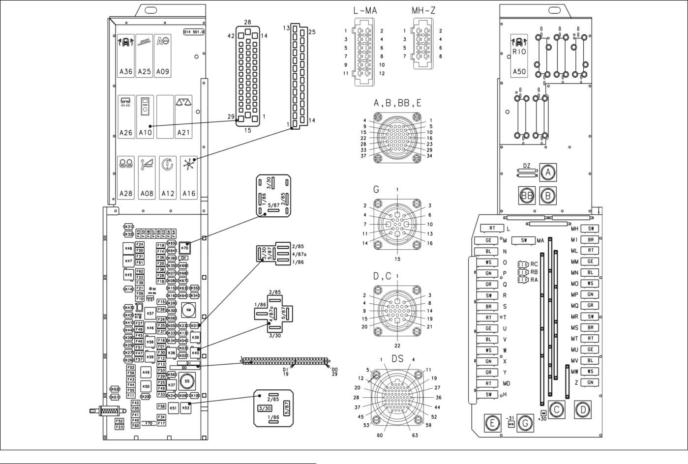
D-S
Central terminal compartment
014 501.0
Montana (with RIO module A50)
Electric System |
LEXION Montana |
TIC |
D-S - Central terminal compartment on Montana machines 014 501.0 (with RIO module A50)
ZE-s-2 |
Lex-e-ZE |
03/04 |
D-S
Central terminal compartment
014 501.0
Montana (with HBM module A45)

Electric System |
LEXION Montana |
TIC |
D-S - Central terminal compartment on Montana machines 014 501.0 (with HBM module A45)
ZE-s-4 |
Lex-e-ZE |
03/04 |
TIC |
LEXION Montana |
Electric System |
|
|
|
Key to diagram: |
Modules |
|
|
|
|
A08 |
AUTOCONTOUR module (CAC) |
|
A09 |
AUTOPILOT module |
|
A10 |
Fieldwork computer module (BIF/CAB) |
|
A12 |
Speed monitor module (DZW) |
|
A16 |
Reel controller module (HAS) |
|
A21 |
YIELD METER module (LEM) |
|
A25 |
Sieve adjustment module |
|
A26 |
Deflector adjustment module |
|
A28 |
Uni-spreader module (VGS) |
|
A36 |
Electro-hydraulic gearshift module |
|
A45 |
Ground drive hydraulic motor brake restrictor module (HBM) |
|
A50 |
RIO module (ground drive hydraulic motor brake restrictor) |
|
|
Electronic components |
|
DI |
Warning device diode PCB |
|
D0 |
Master valve diode PCB |
|
DS |
Diagnosis (63-pin) VIA |
|
|
Fuses |
|
F1 |
Dipped headlights circuit |
|
F2 |
Sieve adjustment module 12 V control unit |
|
F3 |
CAN connection of performance monitor |
|
F4 |
+12 V electronic unit |
|
F5 |
12 V air conditioner fan |
|
F6 |
## |
|
F7 |
CAC module |
|
F8 |
Reel module |
|
F9 |
Yield meter |
|
F10 |
Yield meter |
|
F11 |
Inside work lights |
|
F12 |
Work lights |
|
F13 |
Cigarette lighter |
|
F14 |
Seat socket |
|
F15 |
Drum/rotor speed adjustment |
|
F16 |
Concave adjustment |
|
F17 |
Diagnosis LED |
|
F18 |
Cutterbar |
|
F19 |
Engine speed switch |
|
F20 |
All-wheel drive 12 V switch |
|
F21 |
Threshing mechanism relay |
|
F22 |
Fan speed relay |
|
F23 |
Hazard warning switch 30 |
|
F24 |
Hazard warning switch 15 |
|
F25 |
Fan speed relay |
|
F26 |
Reel controller |
|
F27 |
Upper/lower sieve |
|
F28 |
Autopilot switch |
|
F29 |
12 V / K56 pin 30 |
|
F30 |
Brake light switch 12 V / Sieve pan light |
|
F31 |
12 V IMO |
|
F32 |
12 V IMO |
|
F33 |
Air conditioner relay |
|
F34 |
Engine control unit 12 V power supply |
|
F35 |
CAC module / VGS module |
|
03/04 |
Lex-e-ZE |
ZE-s-5 |

Electric System |
LEXION Montana |
TIC |
Key to diagram: |
|
|
F36 |
Fuses |
|
Grain tank extension |
|
|
F37 |
12 V grain tank drive |
|
F38 |
Work light |
|
F39 |
Chopper On/Off pushbutton |
|
F40 |
Vehicle lighting switch 12 V |
|
F41 |
Warning beacon |
|
F42 |
12 V horn / wiper and washer system |
|
F43 |
Position light, left-hand |
|
F44 |
Position light, right-hand |
|
F45 |
Left-hand full beam relay |
|
F46 |
Left-hand dipped beam relay |
|
F47 |
Right-hand full beam relay |
|
F48 |
Right-hand dipped beam relay |
|
F49 |
Table adjustment |
|
F50 |
Grain tank extension |
|
F51 |
Ignition diagnosis plug |
|
F52 |
Instrument lighting |
|
F53 |
Returns lighting |
|
F54 |
Uni-spreader/Autopilot module |
|
F55 |
Worklight switch |
|
F56 |
Spare module |
|
F57 |
Spare module |
|
F58 |
Spare (connector H) |
|
F59 |
Engine diagnosis |
|
F60 |
12 V sockets LP/HP |
|
F61 |
### |
|
F62 |
Outside railing worklights relay |
|
F63 |
12 V sensors power supply |
|
F64 |
### |
|
F65 |
### |
|
F70 |
Ignition switch back-up fuse |
|
ZE-s-6 |
Lex-e-ZE |
03/04 |

TIC |
LEXION Montana |
Electric System |
|
|
|
Key to diagram: |
Relays |
|
|
|
|
K1 |
Raise reel |
|
K2 |
Lower reel |
|
K3 |
Reel forward |
|
K4 |
Reel backward |
|
K5 |
Raise cutterbar |
|
K6 |
Lower cutterbar |
|
K7 |
Cutterbar left-hand cross levelling |
|
K8 |
Cutterbar right-hand cross levelling |
|
K9 |
Table adjustment forward |
|
K10 |
Table adjustment backward |
|
K13 |
Threshing mechanism On/Off |
|
K14 |
Threshing mechanism On/Off |
|
K15 |
Cutterbar |
|
K16 |
Cutterbar |
|
K20 |
Lighting main relay |
|
K23 |
Alternator |
|
K24 |
Air conditioner relay |
|
K25 |
Left-hand full beam relay |
|
K26 |
Right-hand full beam relay |
|
K27 |
Left-hand dipped beam relay |
|
K28 |
Right-hand dipped beam relay |
|
K29 |
Drum speed adjustment relay |
|
K30 |
Drum speed adjustment relay |
|
K31 |
Grain tank extension up |
|
K32 |
Grain tank extension down |
|
K33 |
Concave clearance + |
|
K34 |
Concave clearance - |
|
K35 |
Front attachment speed + |
|
K36 |
Front attachment speed - |
|
K37 |
Fan speed + |
|
K38 |
Fan speed - |
|
K39 |
Reel speed - |
|
K40 |
Reel speed + |
|
03/04 |
Lex-e-ZE |
ZE-s-7 |

Electric System |
LEXION Montana |
TIC |
Key to diagram: |
Relays |
|
|
|
|
K41 |
Upper sieve adjustment - |
|
K42 |
Upper sieve adjustment + |
|
K43 |
Lower sieve adjustment - |
|
K44 |
Lower sieve adjustment + |
|
K45 |
Work lights |
|
K46 |
Grain tank unloading tube swing time relay |
|
K47 |
Flash relay USA |
|
K48 |
Indicator relay Europe |
|
K49 |
Road travel main relay |
|
K50 |
Work lights relay |
|
K51 |
Relay 15 |
|
K53 |
Start relay |
|
K54 |
Rotor variator + |
|
K55 |
Rotor variator - |
|
K56 |
Plus 15 power supply |
|
K57 |
Transducer |
|
K58 |
Alternator relay |
|
K59 |
Work lights relay |
|
K61 |
Warning beacon |
|
K62 |
Warning beacon grain tank 70% full |
|
K63 |
Fan speed relay |
|
K64 |
Reel speed relay |
|
K67 |
Spare relay |
|
K68 |
Spare relay |
|
K69 |
Spare relay |
|
K70 |
Grain tank unloading relay |
|
ZE-s-8 |
Lex-e-ZE |
03/04 |

TIC |
LEXION Montana |
Electric System |
|
|
|
Module A35 - Montana control unit, for Montana machines (with RIO module A50)
Pin |
Function |
Component |
Measuring |
Direction |
Circuit |
|
|
|
variable |
|
diagram no. |
1 |
Earth |
A41 |
Earth |
Output |
05S |
2 |
CAN Low Montana |
A41 |
- |
Output |
05S |
3 |
CAN High Montana |
A41 |
- |
Output |
05S |
4 |
Power supply (CAN) |
A41 |
12 V |
Output |
05S |
5 |
not used |
--- |
--- |
--- |
--- |
6 |
Parking brake signal |
S93 |
12 V |
Input |
41S |
7 |
Montana cross levelling sensor signal |
B94 |
0.25-4.75 V |
Input |
41S |
8 |
Montana feed rake conveyor sensor signal |
B95 |
0.25-4.75 V |
Input |
41S |
9 |
Right-hand axle angle sensor signal |
B92 |
0.25-4.75 V |
Input |
41S |
10 |
not used |
--- |
--- |
--- |
--- |
11 |
Oil quantity increase |
Y118 |
12 V |
Output |
41S |
12 |
Master valve (Montana) |
Y128 |
12 V |
Output |
4S, 4t |
13 |
Lower axle, right-hand side |
Y116 |
12 V |
Output |
41S |
14 |
Raise axle, right-hand side |
Y117 |
12 V |
Output |
41S |
15 |
Rotate front attachment to the right |
Y112 |
12 V |
Output |
41S |
16 |
Lower cutting angle |
Y111 |
12 V |
Output |
41S |
17 |
Power supply (K69) |
--- |
12 V |
Input |
41S, 4S |
18 |
Power supply (K69) |
--- |
12 V |
Input |
41S, 4S |
19 |
RS 232 |
--- |
--- |
--- |
05S |
20 |
RS 232 |
--- |
--- |
--- |
05S |
21 |
RS 232 |
--- |
--- |
--- |
05S |
22 |
RS 232 (Boot) |
--- |
--- |
--- |
05S |
23 |
not used |
--- |
--- |
--- |
--- |
24 |
Earth sensors |
B91, B92, |
Earth |
Output |
41S |
|
|
B93, B94, |
|
|
|
|
|
B95 |
|
|
|
25 |
Cutting angle sensor signal |
B93 |
0.25-4.75 V |
Input |
41S |
26 |
Left-hand axle angle sensor signal |
B91 |
0.25-4.75 V |
Input |
41S |
27 |
Power supply of sensors |
B91, B92, |
12 V |
Output |
41S |
|
|
B93, B94, |
|
|
|
|
|
B95 |
|
|
|
28 |
not used |
--- |
--- |
--- |
--- |
29 |
Master valve (Working hydraulics) |
Y77 |
12 V |
Output |
4S |
30 |
Lower axle, left-hand side |
Y114 |
12 V |
Output |
41S |
31 |
Raise axle, left-hand side |
Y115 |
12 V |
Output |
41S |
32 |
Rotate front attachment to the left |
Y113 |
12 V |
Output |
41S |
33 |
Raise cutting angle |
Y110 |
12 V |
Output |
41S |
34 |
Earth |
--- |
Earth |
Input |
41S, 4S |
35 |
Earth |
--- |
Earth |
Input |
41S, 4S |
03/04 |
Lex-e-ZE |
ZE-s-9 |

Electric System |
LEXION Montana |
TIC |
Module A35 - Montana control unit, for Montana machines (with HBM module A45)
Pin |
Function |
Component |
Measuring |
Direction |
Circuit |
|
|
|
variable |
|
diagram no. |
1 |
Power supply (K69) |
--- |
12 V |
Input |
41t, 4t |
2 |
Lower axle, left-hand side |
Y114 |
12 V |
Output |
41t |
3 |
Raise axle, left-hand side |
Y115 |
12 V |
Output |
41t |
4 |
Raise axle, right-hand side |
Y117 |
12V |
Output |
41t |
5 |
Lower axle, right-hand side |
Y116 |
12 V |
Output |
41t |
6 |
Rotate front attachment to the left |
Y113 |
12 V |
Output |
41t |
7 |
Rotate front attachment to the right |
Y112 |
12 V |
Output |
41t |
8 |
Raise cutting angle |
Y110 |
12 V |
Output |
41t |
9 |
Lower cutting angle |
Y111 |
12 V |
Output |
41t |
10 |
Master valve (Montana) |
Y128 |
12 V |
Output |
4t |
11 |
Master valve (Working hydraulics) |
Y77 |
12 V |
Output |
4t |
12 |
Oil quantity increase |
Y118 |
12 V |
Output |
41t |
13 |
not used |
--- |
--- |
--- |
--- |
14 |
Earth |
--- |
Earth |
Input |
41t |
15 |
Power supply (K69) |
--- |
12 V |
Input |
41t, 4t |
16 |
Left-hand axle angle sensor signal |
B91 |
0.25-4.75 V |
Input |
41t |
17 |
Montana cross levelling sensor signal |
B94 |
0.25-4.75 V |
Input |
41t |
18 |
not used |
--- |
--- |
--- |
--- |
19 |
not used |
--- |
--- |
--- |
--- |
20 |
not used |
--- |
--- |
--- |
--- |
21 |
CAN Low (Inclinometer) |
B126 |
- |
Output |
05t |
22 |
not used |
--- |
--- |
--- |
--- |
23 |
CAN Low (Montana) |
A41 |
- |
Output |
05t |
24 |
Earth |
A41 |
Earth |
Output |
05t |
25 |
RS 232 |
--- |
--- |
--- |
05t |
26 |
RS 232 |
--- |
--- |
--- |
05t |
27 |
not used |
--- |
--- |
--- |
--- |
28 |
Earth |
--- |
Earth |
Input |
41t |
29 |
Power supply (K69) |
--- |
12 V |
Input |
4t |
30 |
Right-hand axle angle sensor signal |
B92 |
0.25-4.75 V |
Input |
41t |
31 |
Cutting angle sensor signal |
B93 |
0.25-4.75 V |
Input |
41t |
32 |
Parking brake signal |
S93 |
12V |
Input |
41t |
33 |
Earth sensors |
B91, B92, |
Earth |
Output |
41t |
|
|
B93, B94, |
|
|
|
|
|
B95, B126 |
|
|
|
34 |
not used |
--- |
--- |
--- |
--- |
35 |
not used |
--- |
--- |
--- |
--- |
36 |
CAN High (Inclinometer) |
B126 |
- |
Output |
05t |
37 |
Power supply (CAN) |
A41 |
12 V |
Output |
05t |
38 |
CAN High (Montana) |
A41 |
- |
Output |
05t |
39 |
RS 232 (Boot) |
--- |
--- |
--- |
05t |
40 |
RS 232 |
--- |
--- |
--- |
05t |
41 |
not used |
--- |
--- |
--- |
--- |
42 |
not used |
--- |
--- |
--- |
--- |
ZE-s-10 |
Lex-e-ZE |
03/04 |

TIC |
|
|
LEXION Montana |
|
|
|
Electric System |
||||||||||||
|
|
|
|
|
|
|
|
|
|
|
|
|
|
|
|
|
|
|
|
Module A36 - Montana gearshift module |
|
|
|
|
|
|
|
|
|
|
|
|
|
|
|||||
|
|
|
|
|
|
|
|
|
|
|
|
|
|
|
|
|
|
|
|
|
|
Pin |
|
|
Function |
|
|
Component |
|
|
Measuring |
|
|
Direction |
|
|
Circuit |
|
|
|
|
|
|
|
|
|
|
|
|
|
variable |
|
|
|
|
|
diagram no. |
|
|
|
1 |
|
|
Earth |
|
--- |
|
|
Earth |
|
|
Input |
|
|
42s, 42t |
||||
|
2 |
|
|
Power supply (+15) |
|
|
K56 |
|
12 V |
|
|
Input |
|
|
42s, 42t |
||||
|
3 |
|
|
Gearbox shifting release |
|
|
S90 |
|
12 V |
|
|
Output |
|
|
42s, |
42t |
|||
|
4 |
|
|
2nd gear signal |
|
|
Z83 |
|
12 V |
|
|
Input |
|
|
42s, 42t |
||||
|
5 |
|
|
1st gear signal |
|
|
Z82 |
|
12 V |
|
|
Input |
|
|
42s, 42t |
||||
|
6 |
|
|
Gearbox shift 1st gear |
|
|
Y107 |
|
12 V |
|
|
Output |
|
|
42s, 42t |
||||
|
7 |
|
|
Gearbox shift 2nd gear |
|
|
Y108 |
|
12 V |
|
|
Output |
|
|
42s, |
42t |
|||
|
8 |
|
|
Ground speed control lever neutral signal |
|
|
Z57 |
|
Earth |
|
|
Input |
|
|
1s;42s, 42t |
||||
|
9 |
|
|
Ground drive control pressure circuit SH |
|
|
Y125 |
|
12 V |
|
|
Output |
|
|
42s, 42t |
||||
|
10 |
|
|
Engine speed maximum |
|
--- |
|
|
12 V – 1st gear |
|
|
Output |
|
|
42s, 42t |
||||
|
|
|
|
|
reduced |
|
|
|
|
|
0 V – 2nd gear |
|
|
|
|
|
|
|
|
|
11 |
|
|
Engine speed (Gearshift control) |
|
--- |
|
|
12 V |
|
|
Input |
|
|
42s, 42t |
||||
|
12 |
|
Parking brake circuit |
|
|
Y123 |
|
12 V |
|
|
Input |
|
|
42s, 42t |
|||||
|
13 |
|
Shifting aid uphill signal |
|
|
Y121 |
|
12 V |
|
|
Input |
|
|
42s, 42t |
|||||
|
14 |
|
|
Shifting aid downhill signal |
|
|
Y122 |
|
12 V |
|
|
Input |
|
|
42s, 42t |
||||
|
15 |
|
Working hydraulics master valve |
|
|
Y77 |
|
12 V |
|
|
Output |
|
|
4s, |
4t |
||||
|
16 |
|
Working hydraulics master valve |
|
|
Y77 |
|
12 V |
|
|
Output |
|
|
4s, |
4t |
||||
|
17 |
|
Montana master valve |
|
|
Y128 |
|
12 V |
|
|
Output |
|
|
4s, 4t |
|||||
|
18 |
|
Montana master valve |
|
|
Y128 |
|
12 V |
|
|
Input |
|
|
4s, 4t |
|||||
|
19 |
|
Montana master valve |
|
|
Y128 |
|
12 V |
|
|
Input |
|
|
4s |
|||||
|
20 |
|
Working hydraulics master valve |
|
|
Y77 |
|
12 V |
|
|
Input |
|
|
4s, |
4t |
||||
|
21 |
|
Working hydraulics master valve |
|
|
Y77 |
|
12 V |
|
|
Input |
|
|
4s, |
4t |
||||
|
22 |
|
Working hydraulics master valve |
|
|
Y77 |
|
12 V |
|
|
Input |
|
|
4s, |
4t |
||||
|
23 |
|
Working hydraulics master valve |
|
|
Y77 |
|
12 V |
|
|
Input |
|
|
4s, |
4t |
||||
|
24 |
|
Shifting aid |
|
|
Y121; Y122 |
|
12 V |
|
|
Output |
|
|
42s, 42t |
|||||
|
25 |
|
|
not used |
|
--- |
|
|
--- |
|
--- |
|
--- |
|
|||||
03/04 |
Lex-e-ZE |
ZE-s-11 |

Electric System |
LEXION Montana |
TIC |
Module A45 - Ground drive hydraulic motor brake restrictor (HBM)
|
Pin |
|
|
Function |
|
|
Component |
|
|
Measuring |
|
|
Direction |
|
|
Circuit |
|
|
|
|
|
|
|
|
|
|
|
variable |
|
|
|
|
|
diagram no. |
|
|
1 |
|
--- |
|
--- |
|
--- |
|
--- |
|
--- |
|
|||||
|
2 |
|
|
Master valve |
|
|
Y77 |
|
|
12 V |
|
|
Output |
|
|
42t |
|
|
3 |
|
|
CAN high |
|
- |
|
- |
|
- |
|
|
6t |
|
|||
|
4 |
|
|
Power +15 |
|
|
K51/87 |
|
|
12 V |
|
|
Input |
|
|
6t |
|
|
5 |
|
|
--- |
|
--- |
|
--- |
|
--- |
|
--- |
|
||||
|
6 |
|
|
Earth (GND) |
|
-31 |
|
|
Earth |
|
|
Input |
|
|
6t |
|
|
|
7 |
|
|
--- |
|
--- |
|
--- |
|
--- |
|
--- |
|
||||
|
8 |
|
|
Brake restrictor |
|
|
Y124 |
|
|
12 V |
|
|
Output |
|
|
42t |
|
|
9 |
|
|
CAN low |
|
- |
|
- |
|
- |
|
|
6t |
|
|||
Module A50 - Montana RIO module |
|
|
|
|
|
Pin |
Function |
Component |
Measuring |
Direction |
Circuit |
|
|
|
variable |
|
diagram no. |
R0/1 |
+12 V electronic unit |
--- |
--- |
--- |
--- |
R0/2 |
+12 V power |
--- |
--- |
--- |
--- |
R0/3 |
Output 1 Montana master valve |
Y128 |
12 V |
Output |
4s, 42s |
R0/4 |
Ground drive hydraulic motor brake |
Y124 |
12 V |
Output |
42s |
|
restrictor (output 3) |
|
|
|
|
R0/5 |
Working hydraulics |
Y77 |
12 V |
Output |
4s, 42s |
|
master valve output 2 |
|
|
|
|
R0/6 |
Output 4 |
--- |
--- |
--- |
--- |
R0/7 |
Sensor 1 |
--- |
--- |
--- |
--- |
R0/8 |
Sensor 2 |
--- |
--- |
--- |
--- |
R0/9 |
Earth |
--- |
--- |
--- |
--- |
R0/10 |
Earth |
--- |
--- |
--- |
--- |
R0/11 |
Module code 1 |
--- |
--- |
--- |
--- |
R0/12 |
Module code 2 |
--- |
--- |
--- |
--- |
R0/13 |
Module code 3 |
--- |
--- |
--- |
--- |
R0/14 |
Module code 4 |
--- |
--- |
--- |
--- |
R0/15 |
Sensor 3 |
--- |
--- |
--- |
--- |
R0/16 |
Sensor 4 |
|
|
|
|
|
|
|
|
|
|
R1/1 |
CAN low |
--- |
--- |
--- |
6s |
R1/2 |
+12 V electronic unit |
--- |
12 V |
Input |
2s, 6s |
R1/3 |
+12 V power |
--- |
12 V |
Input |
2s, 6s |
R1/4 |
CAN high |
--- |
--- |
--- |
6s |
R1/5 |
Earth |
--- |
Earth |
Input |
6s |
R1/6 |
Earth |
--- |
Earth |
Input |
6s |
ZE-s-12 |
Lex-e-ZE |
03/04 |
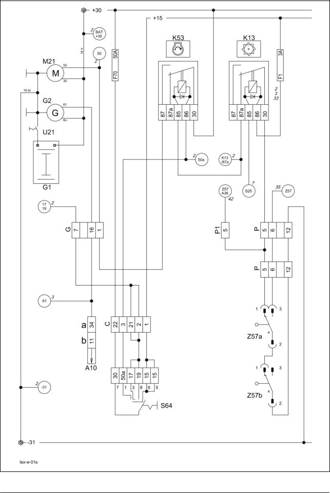
01s
Main power supply,
Diesel engine electric starting motor
for Montana machines
Electric System |
LEXION Montana |
TIC |
01s - Main power supply, diesel engine electric starting motor, for Montana machines
Key to diagram: |
|
Coordinates |
A10 |
Fieldwork computer module (BIF/CAB) ............................. |
2-h-20 |
G1 |
Battery................................................................................ |
7-n-21 |
G2 |
Generator........................................................................... |
1-g-17 |
K13 |
Threshing mechanism relay............................................... |
3-h-20 |
K53 |
Start relay........................................................................... |
3-h-20 |
M21 |
Electric starting motor ........................................................ |
3-n-19 |
S64 |
Ignition switch ..................................................................... |
3-f-18 |
U21 |
Battery isolating switch ...................................................... |
6-o-20 |
Z57 |
Ground speed control lever |
|
|
neutral position switch - safety start switch ....................... |
3-g-18 |
Measured value table: |
Item |
Component |
Measured value |
Remark |
|
K13 |
Remote control relay |
95±10 Ω |
(Pin 86/1 – 85/2) |
|
|
15 A |
|
(Pin 87a/4 – 30/3) |
|
|
30 A |
|
(Pin 87/5 – 30/3) |
|
K53 |
Remote control relay |
115±10 Ω |
(Pin 86/1 – 85/2) |
|
|
70 A |
|
(Pin 87/5 – 30/3) |
1s-2 |
Lex-e-01s |
03/04 |
TIC |
LEXION-Montana |
Electric System |
|
|
|
Description of function: |
|
|
Montana machine: |
In this circuit, the difference between the standard machine and the |
|
|
Montana machine is only in a cable branch at connector P to P1. The |
|
|
signal of ground speed control lever in neutral position (Z57) is required |
|
|
on Montana machines for releasing the gear shifting. |
|
Diesel engine electric |
As a safety start switch, relay K53 is supplied with earth only when |
|
starting motor |
switches (Z57a/Z57b) on the ground speed control lever are in neutral |
|
|
position and the threshing mechanism is disengaged via relay K13. The |
|
|
ignition lock (S64) then actuates the diesel engine starting motor (M21) |
|
|
via relay K53 with +50a. |
|
03/04 |
Lex-e-01s |
1s-3 |
Electric System |
|
LEXION Montana |
|
TIC |
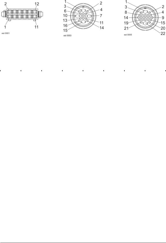
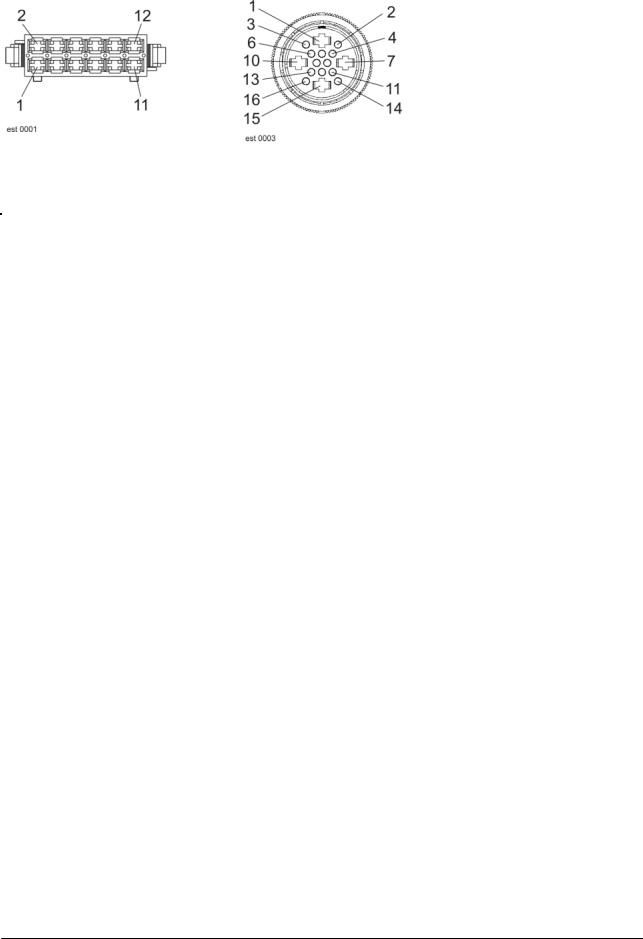
Connector pin definition: |
|
|
|
|
Connector P, P1 |
|
Connector G |
|
Connector C |
|
|
|
|
|
Interconnection list:
from |
to 1 |
to 2 |
to 3 |
to 4 |
to 5 |
mm² |
Colour |
C-1 |
15 |
|
|
|
|
6 |
bk |
C-2 |
G-7 |
C-21 |
|
|
|
1.5 |
bk-rd |
C-3 |
K53-86 |
K56-86 |
K52-86 |
|
|
0.75 |
bk-ye |
C-21 |
G-7 |
C-2 |
|
|
|
1.5 |
bk-rd |
C-22 |
30 |
|
|
|
|
6 |
rd |
|
|
|
|
|
|
|
|
G-1 |
K53-87 |
DS-43 |
|
|
|
4 |
bk-ye |
G-7 |
C-2 |
C-21 |
|
|
|
1.5 |
bk-rd |
G-16 |
C-18 |
K58-86 |
Cab-34 / |
|
|
0.75 |
bl |
|
|
|
Bif-11 |
|
|
|
|
|
|
|
|
|
|
|
|
P-5 |
K13-30 |
|
|
|
|
1.5 |
vi-br |
P-6 |
X-7 |
DI-7 |
|
|
|
1.5 |
vi-ye |
P-12 |
31 |
|
|
|
|
2.5 |
br |
|
|
|
|
|
|
|
|
P1-5 |
P-5 |
A36-8 |
|
|
|
1.5 |
vi-bl |
1s-4 |
Lex-e-01s |
03/04 |
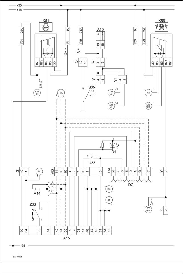
02s
Starting the diesel engine, Diesel engine speed adjustment
for Montana machines
Electric System |
LEXION Montana |
TIC |
02s - Starting the diesel engine, diesel engine speed adjustment - for Montana machines
Key to diagram: |
|
Coordinates |
A10 |
Fieldwork computer module (BIF/CAB) ............................. |
2-h-20 |
A15 |
Electronic engine control module ...................................... |
2-o-18 |
D1 |
Diesel engine error code LED............................................ |
3-h-20 |
DC |
Caterpillar diagnosis .......................................................... |
3-h-20 |
K51 |
Ignition switch relay ........................................................... |
3-h-20 |
K56 |
Montana relay .................................................................... |
3-h-20 |
R14 |
CAN bus matching resistor (J1939)................................... |
3-h-20 |
S35 |
Engine speed adjustment switch ....................................... |
3-g-17 |
U22 |
Diesel engine diagnosis switch.......................................... |
3-h-20 |
Z33 |
Coolant level switch without engine cut-off system .......... |
1-m-17 |
Measured value table: |
Item |
Component |
Measured value |
Remark |
|
K51 |
Remote control relay |
115±10 Ω |
(Pin 86/1 – 85/2) |
|
|
70 A |
|
(Pin 87/5 – 30/3) |
2s-2 |
Lex-e-02s |
03/04 |

TIC |
LEXION Montana |
Electric System |
||||
|
|
|
|
|
|
|
Description of function: |
|
|
|
|
|
|
Montana machine: |
In this circuit, the difference between the standard machine and the |
|||||
|
Montana machine is only in a cable branch at connector Y to Y1. The |
|||||
|
gearbox switch on connector Y is dropped for Montana machines. |
|||||
|
The Montana functions are supplied with power via the unactuated relay |
|||||
|
K56. During the starting process, relay K56 is actuated and thus interrupts |
|||||
|
the power supply. |
|
|
|
|
|
Starting |
The safety start switch circuit of this engine is identical with the one used |
|||||
|
on the mechanically controlled engines. |
|
|
|
||
|
The engine controller module (A15) is activated via relay K51 by the |
|||||
|
ignition lock (S64). During the starting procedure, the engine controller |
|||||
|
module (A15) receives the speed signal from the sensor provided on the |
|||||
|
camshaft and starts the injection. |
|
|
|
||
Engine monitoring |
All sensors relevant for operation and monitoring of the engine are |
|||||
|
mounted on the engine wiring loom. Only the water level sensor is |
|||||
|
connected to the CLAAS wiring loom. |
|
|
|
||
|
The engine controller module (A15) transmits the signals for displaying |
|||||
|
the engine speed and the coolant temperature to the CAB module (A10) |
|||||
|
via the CAN bus J1939. The CAN module (A10) converts this signal to the |
|||||
|
CLAAS CAN bus, thus allowing display on the terminal. |
|
|
|||
Engine diagnosis |
The number of the engine errors occurred and the corresponding error |
|||||
|
codes can be displayed in the terminal |
|
|
|
||
|
(see also the error code list in the Electric System documentation |
|||||
|
297550.x - Diagram 2e). |
|
|
|
|
|
|
Further diagnosis is carried out via the diagnosis plug in the central |
|||||
|
terminal compartment, using the Caterpillar diagnosis tool CAT-ET. The |
|||||
|
display of error codes can also be activated by the diagnosis LED (D1) |
|||||
|
after actuating the rocker switch (U22). |
|
|
|
||
Diesel engine speed |
The diesel engine speed depends on the position of switch S35 and of the |
|||||
adjustment |
2nd gear actual value switch (Z83) – see also circuit diagram 42s. |
|||||
|
If full throttle speed is selected and the 2nd gear engaged (signal input |
|||||
|
A36 / pin 4), the connection between Z41a and Z41b inside the Montana |
|||||
|
gearshift control module (A36) is cut (pins 10 and 11) – see also circuit |
|||||
|
diagram 42s. |
|
|
|
|
|
|
The full throttle speed is reduced to road travel speed, depending on the |
|||||
|
contry version. The maximum speed which can be achieved now can be |
|||||
|
configured using the Claas diagnosis system CDS. |
|
|
|||
|
|
|
|
|
|
|
|
LEXION |
Idle speed |
Full throttle at |
20km/h |
25km/h |
|
|
Type |
(S35) |
no load |
(Z83) |
(Z83) |
|
|
|
|
(S35) |
|
|
|
|
Montana |
1200 rpm |
2100 rpm |
1568 rpm |
1960 rpm |
|
|
470-420 |
|
|
|
|
|
03/04 |
Lex-e-02s |
2s-3 |
Electric System |
|
LEXION Montana |
TIC |
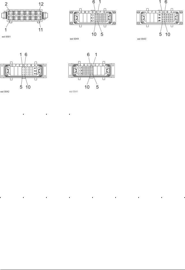
Connector pin definition: |
|
|
|
Connector MD, O, Y, Y1 |
|
Connector G |
|
|
|
|
|
Interconnection list:
from |
to 1 |
to 2 |
to 3 |
to 4 |
to 5 |
mm² |
Colour |
G-1 |
K53-87 |
DS-43 |
A15-64 |
M21-50 |
|
4 |
bk-ye |
G-10 |
F34-A |
DS-4 |
A15-70 |
|
|
4 |
bk-rd |
|
|
|
|
|
|
|
|
Y-3 |
W-7 |
DS-2 |
Cab-18 |
|
|
1.5 |
br-wh |
Y-4 |
W-6 |
DS-1 |
O-10 |
Cab-19 |
|
1.5 |
br-ye |
Y-9 |
K56-87a |
DS-3 |
|
|
|
1.5 |
bk |
|
|
|
|
|
|
|
|
O-10 |
W-6 |
DS-1 |
Y-4 |
Cab-19 |
|
1.5 |
wh-rd |
O-12 |
F19-A |
|
|
|
|
2.5 |
bk |
|
|
|
|
|
|
|
|
MD-1 |
30 |
A15-48 |
A15-52 |
A15-53 |
|
0.5 |
wh |
MD-4 |
A15-8 |
XM-D |
|
|
|
0.5 |
wh |
MD-5 |
A15-9 |
XM-E |
|
|
|
0.5 |
wh |
MD-6 |
31 |
A15-61 |
A15-62 |
A15-63 |
XM-B |
|
|
|
U22-1 |
|
|
|
|
0.5 |
wh |
MD-7 |
A15-28 |
D2-K |
|
|
|
0.5 |
wh |
MD-8 |
A15-44 |
U22-2 |
|
|
|
0.5 |
wh |
MD-9 |
A15-34 |
R14-B |
|
|
|
0.5 |
wh |
MD-10 |
A15-50 |
R14-A |
|
|
|
0.5 |
wh |
MD-11 |
A15-42 |
R14-C |
|
|
|
0.5 |
wh |
|
|
|
|
|
|
|
|
XM-A |
F59-A |
|
|
|
|
0.5 |
wh |
XM-B |
MD-6 |
U22-1 |
|
|
|
0.5 |
wh |
XM-C |
MD-11 |
|
|
|
|
0.5 |
wh |
XM-D |
MD-4 |
|
|
|
|
0.5 |
wh |
XM-E |
MD-5 |
|
|
|
|
0.5 |
wh |
XM-F |
MD-9 |
|
|
|
|
0.5 |
wh |
XM-G |
MD-10 |
|
|
|
|
0.5 |
wh |
|
|
|
|
|
|
|
|
Y1-3 |
Y-3 |
A36-10 |
|
|
|
1.5 |
br-gr |
Y1-4 |
Y-4 |
A36-11 |
|
|
|
1.5 |
br-ye |
Y1-9 |
Y-9 |
A50-RI-2+3 |
XSA-C4 |
XSA-B5 |
A36-2 |
1.5 |
bk |
2s-4 |
Lex-e-02s |
03/04 |
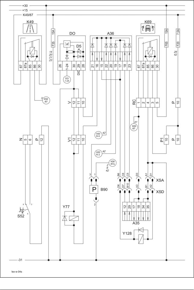
4s
Road travel activation, master valve
for Montana machines (with RIO module A50)
Electric System |
LEXION Montana |
TIC |
04s - Road travel activation, working hydraulics master valve, for Montana machines with module A50 (RIO)
Key to diagram: |
|
Coordinates |
A35 |
Montana control unit module ............................................... |
7-i-18 |
A36 |
Montana gearshift control module ..................................... |
2-h-20 |
B90 |
Brake accumulator pressure sensor/switch....................... |
5-g-20 |
DO |
Master valve diode PCB .................................................... |
3-h-20 |
D5 |
Master valve DO diode PCB LED...................................... |
3-h-20 |
K49 |
Road travel main relay....................................................... |
3-h-20 |
K69 |
Montana relay .................................................................... |
3-h-20 |
S52 |
Road travel switch (red)..................................................... |
3-g-17 |
Y77 |
Working hydraulics master valve solenoid coil ................. |
6-m-21 |
Y128 |
Montana master valve solenoid coil .................................. |
7-h-18 |
Measured value table: |
Item |
Component |
Measured value |
Remark |
|
B90 |
Brake circuit oil |
ON |
< 135 bar |
|
|
pressure / charge |
OFF |
> 165 bar |
|
|
pressure |
|
|
|
K49 |
Remote control relay |
115±10 Ω |
(Pin 86/1 – 85/2) |
|
|
70 A |
|
(Pin 87/5 – 30/3) |
|
K69 |
Remote control relay |
95±10 Ω |
(Pin 86/1 – 85/2) |
|
|
15 A |
|
(Pin 87a/4 – 30/3) |
|
|
30 A |
|
(Pin 87/5 – 30/3) |
|
Y77 |
Solenoid coil |
3.8 A |
|
|
Y128 |
|
3.2 Ω |
|
4s-2 |
Lex-e-04s |
03/04 |

TIC |
LEXION Montana |
Electric System |
|
|
|
Description of function:
Montana machine:
Activation of road travel
Working hydraulics master valve
Montana axle hydraulics master valve
Montana brake pressure accumulator
Increased brake effect Montana – only with module A50 (RIO)
On Montana machines, actuation of the working hydraulics master valve (Y77) is always via the gearshift control module (A36).
During road travel, the road travel switch (S52) must be locked in order to cut the power supply for all unnecessary electrical and hydraulic functions.
In order to be able to build up the necessary working pressure for many hydraulic controls, the neutral hydraulic circulation must be blocked (see also the "Hydraulic system" section). In this case, the solenoid coil (Y77) is actuated in parallel with the function directly via the diode PCB (DO) and the gearshift control module (A36).
A LED (D5) provided on the diode PCB indicates the activation of the circuit.
For the Montana functions as well, the circulation of the independent axle control system hydraulics must be blocked (see also "Hydraulic System" document).
According to the actuated functions, the Montana control unit (A35) actuates the Montana master valve (Y128) and/or the working hydraulics master valve (Y77) via the gearshift control module (A36).
The sensor/switch (B90) controls the brake system accumulator pressure and, if necessary, actuates the working hydraulics master valve (Y77) via the gearshift control module (A36) in order to recharge the brake circuit accumulator.
If the diesel engine speed drops below 2300 rpm while braking, the RIO module (A50) actuates the working hydraulics master valve (Y77) via A50/pin R5 and the axle hydraulics master valve (Y128) via A50/pin R3. This hydraulic load on the diesel engine increases the braking effect. In addition, a brake restrictor is activated in the hydrostatic ground drive – circuit diagram 42s.
03/04 |
Lex-e-04s |
4s-3 |
Electric System |
|
LEXION Montana |
|
TIC |
Connector pin definition: |
|
|
|
|
Connector N, P, P1, V, V1 |
|
Connector XSA |
|
Connector XSA |
|
|
|
|
|
Connector XSD |
|
Connector XSD |
|
|
|
Interconnection list: I |
|
|
|
|
|
|
|
|
|
|
|
|
|
|
|
from |
to 1 |
to 2 |
to 3 |
to 4 |
to 5 |
mm² |
Colour |
N-5 |
|
|
|
|
|
|
|
N-6 |
K49-85 |
|
|
|
|
0.5 |
br-bl |
|
|
|
|
|
|
|
|
P-10 |
F20-A |
|
|
|
|
1.5 |
gn-rd |
P-12 |
31 |
|
|
|
|
2.5 |
br |
|
|
|
|
|
|
|
|
V-10 |
DO-28 |
A36-21 |
DS-50 |
|
|
1.5 |
pi-wh |
V-11 |
31 |
|
|
|
|
2.5 |
br |
V-12 |
31 |
|
|
|
|
2.5 |
br |
|
|
|
|
|
|
|
|
P1-10 |
P-10 |
|
|
|
|
1.5 |
gn-rd |
|
|
|
|
|
|
|
|
V1-10 |
A36-15+16 |
|
|
|
|
1.5 |
wh-pi |
V1-11 |
V-11 |
|
|
|
|
2.5 |
br |
V1-12 |
V-12 |
|
|
|
|
2.5 |
br |
4s-4 |
Lex-e-04s |
03/04 |
Loading...