

Page 1
LINE THERMAL PRINTER
MODEL CT-S801 Type II
User’s Manual
Mode d’emploi
Benutzerhandbuch
Manuale dell’utente
Manual de Usuario
Page 2

WEEE MARK
En
Wenn Sie dieses Produkt entsorgen wollen, dann tun Sie dies bitte nicht zusammen mit dem
Haushaltsmüll. Es gibt im Rahmen der WEEE-Direktive innerhalb der Europäischen Union
(Direktive 2002/96/EC) gesetzliche Bestimmungen für separate Sammelsysteme für gebrauchte
elektronische Geräte und Produkte.
Ge
Si vous souhaitez vous débarrasser de cet appareil, ne le mettez pas à la poubelle avec vos
ordures ménagères. Il existe un système de récupération distinct pour les vieux appareils
électroniques conformément à la législation WEEE sur le recyclage des déchets des
équipements électriques et électroniques (Directive 2002/96/EC) qui est uniquement valable
dans les pays de l’Union européenne.
Les appareils et les machines électriques et électroniques contiennent souvent des matières
dangereuses pour l’homme et l’environnement si vous les utilisez et vous vous en débarrassez
de façon inappropriée.
Fr
Si desea deshacerse de este producto, no lo mezcle con residuos domésticos de carácter
general. Existe un sistema de recogida selectiva de aparatos electrónicos usados, según
establece la legislación prevista por la Directiva 2002/96/CE sobre residuos de aparatos
eléctricos y electrónicos (RAEE), vigente únicamente en la Unión Europea.
Sp
Se desiderate gettare via questo prodotto, non mescolatelo ai rifiuti generici di casa. Esiste
un sistema di raccolta separato per i prodotti elettronici usati in conformità alla legislazione
RAEE (Direttiva 2002/96/CE), valida solo all’interno dell’Unione Europea.
It
Deponeer dit product niet bij het gewone huishoudelijk afval wanneer u het wilt verwijderen. Er
bestaat ingevolge de WEEE-richtlijn (Richtlijn 2002/96/EG) een speciaal wettelijk
voorgeschreven verzamelsysteem voor gebruikte elektronische producten, welk alleen geldt
binnen de Europese Unie.
Du
Hvis du vil skille dig af med dette produkt, må du ikke smide det ud sammen med dit almindelige
husholdningsaffald. Der findes et separat indsamlingssystem for udtjente elektroniske produkter
i overensstemmelse med lovgivningen under WEEE-direktivet (direktiv 2002/96/EC), som
kun er gældende i den Europæiske Union.
Da
Se quiser deitar fora este produto, não o misture com o lixo comum. De acordo com a legislação
que decorre da Directiva REEE – Resíduos de Equipamentos Eléctricos e Electrónicos (2002/
96/CE), existe um sistema de recolha separado para os equipamentos electrónicos fora de
uso, em vigor apenas na União Europeia.
Por
Pol
Jeżeli zamierzasz pozbyć się tego produktu, nie wyrzucaj go razem ze zwykłymi
domowymi odpadkami. Według dyrektywy WEEE (Dyrektywa 2002/96/EC)
obowiązującej w Unii Europejskiej dla używanych produktów elektronicznych
należy stosować oddzielne sposoby utylizacji.
If you want to dispose of this product, do not mix it with general household waste. There is a
separate collection systems for used electronics products in accordance with legislation under
the WEEE Directive (Directive 2002/96/EC) and is effective only within European Union.
Page 3

Declaration of Conformity
This printer conforms to the following Standards:
The Low Voltage Directive 2006/95/EC, the EMC Directive 2004/108/EC, the RoHS
Directive 2011/65/EU, and the WEEE Directive 2002/96/EC.
LVD : EN60950-1
EMC: EN55022 Class A
EN61000-3-2
EN61000-3-3
EN55024
This declaration applies only to the 230-V model.
IMPORTANT: This equipment generates, uses, and can radiate radio frequency
energy and if not installed and used in accordance with the instruction manual, may
cause interference to radio communications. It has been tested and found to comply
with the limits for a Class A computing device pursuant to Subpart J of Part 15 of FCC
Rules, which are designed to provide reasonable protection against such interference
when operated in a commercial environment. Operation of this equipment in a
residential area is likely to cause interference, in which case the user at his own
expense will be required to take whatever measures may be necessary to correct the
interference.
CAUTION: Use shielded cable for this equipment.
Sicherheitshinweis
Die Steckdose zum Anschluß dieses Druckers muß nahe dem Gerät angebracht und
leicht zugänglich sein.
For Uses in Canada
This Class A Information Technology Equipment (ITE) complies with Canadian CAN
ICES-3(A)/NMB-3(A).
This Information Technology Equipment (ITE) does not exceed the Class A limits for
radio noise emissions from digital apparatus set out in the Radio Interference
Regulations of the Canadian Department of Communications.
Pour L’utilisateurs Canadiens
Cet Equipements informatiques (EI) de la classe A est conforme a la norme CAN ICES3(A)/NMB-3(A) du Canada.
Le present Equipements informatiques (EI) n'emet pas de bruite radio electriques
depassant les limites applicables aux appareils numeriques de la classe A prescrites
dans le Reglement sur le brouillage radioelectrique edicte par le ministere des
Communications du Canada.
Page 4

ENGLISH
Page 5

GENERAL PRECAUTIONS
Before using this product, be sure to read through this manual. After
having read this manual, keep it in a safe, readily accessible place for
future reference.
The information contained herein is subject to change without prior
notice.
Reproduction or transfer of part or all of this document in any means is
prohibited without permission from Citizen Systems.
Note that Citizen Systems is not responsible for any operation results
regardless of omissions, errors, or misprints in this manual.
Note that Citizen Systems is not responsible for any trouble caused as a
result of using options or consumables that are not specified in this
manual.
Except explained elsewhere in this manual, do not attempt to service,
disassemble, or repair this product.
Note that Citizen Systems is not responsible for any damage attributable
to incorrect operation/handling or improper operating environments that
are not specified in this manual.
Data is basically for temporary use and not stored for an extended period
of time or permanently. Please note that Citizen Systems is not
responsible for damage or lost profit resulting from the loss of data
caused by accidents, repairs, tests or other occurrences.
If you find omissions, errors, or have questions, please contact your
Citizen Systems dealer.
If you find any pages missing or out of order, contact your Citizen Systems
dealer for a replacement.
"Made for iPod," "Made for iPhone," and "Made for iPad" mean that an electronic
accessory has been designed to connect specifically to iPod, iPhone, or iPad,
respectively, and has been certified by the developer to meet Apple performance
standards. Apple is not responsible for the operation of this device or its compliance
with safety and regulatory standards.
Please note that the use of this accessory with iPod, iPhone or iPad may affect
wireless performance.
iPad, iPhone and iPod touch are trademarks of Apple Inc., registered in the U.S. and other
countries. iPad Air and iPad mini are trademarks of Apple Inc.
EPSON and ESC/POS are registered trademarks of Seiko Epson Corporation.
QR Code is a registered trademark of DENSO WAVE INCORPORATED.
Ethernet is a registered trademark of Fuji Xerox Corporation.
Bluetooth
CITIZEN is a registered trademark of Citizen Watch Co., Ltd. Japan
All other trademarks are the property of their respective owners.
Citizen Systems use these trademarks in accordance with the license of relevant owners.
®
is a registered trademark of Bluetooth-SIG Inc.
Copyright ©2016 by CITIZEN SYSTEMS JAPAN CO., LTD.
—1—
Page 6
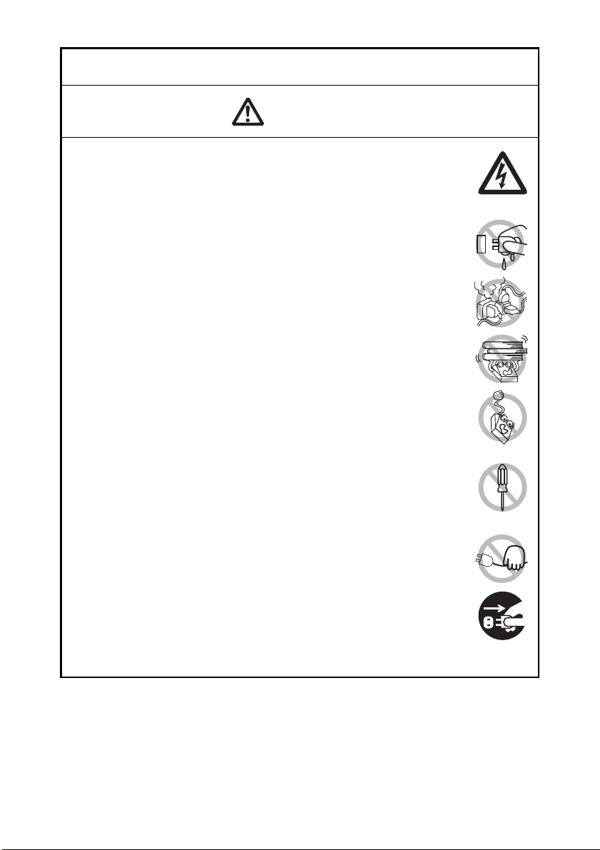
SAFETY PRECAUTIONS
WARNING
CAUTION
Before using this product for the first time, carefully read these SAFETY PRECAUTIONS.
Improper handling may result in accidents (fire, electric shock or injury).
In order to prevent injury to operators, third parties, or damage to property, special
warning symbols are used in the User’s Manual to indicate important items to be strictly
observed.
After having read this Manual, keep it in a safe, readily accessible place for future
reference.
Some of the descriptions contained in this manual may not be relevant to some printer
models.
The following describes the degree of hazard and damage that could occur if the printer
is improperly operated by ignoring the instructions indicated by the warning symbols.
Neglecting precautions indicated by this symbol may result in fatal or serious injury.
Neglecting precautions indicated by this symbol may result in injury or damage to
property.
...WHICH SHOULD BE STRICTLY OBSERVED
This symbol is used to alert your attention to important items.
This symbol is used to alert you to the danger of electric shock or electrostatic
damage.
This symbol denotes a request to unplug the printer from the wall outlet.
This symbol is used to indicate that the power supply must be grounded.
This symbol is used to indicate useful information, such as procedures,
instructions or the like.
This symbol is used to indicate prohibited actions.
—2—
Page 7
PRECAUTIONS ON PRINTER INSTALLATION
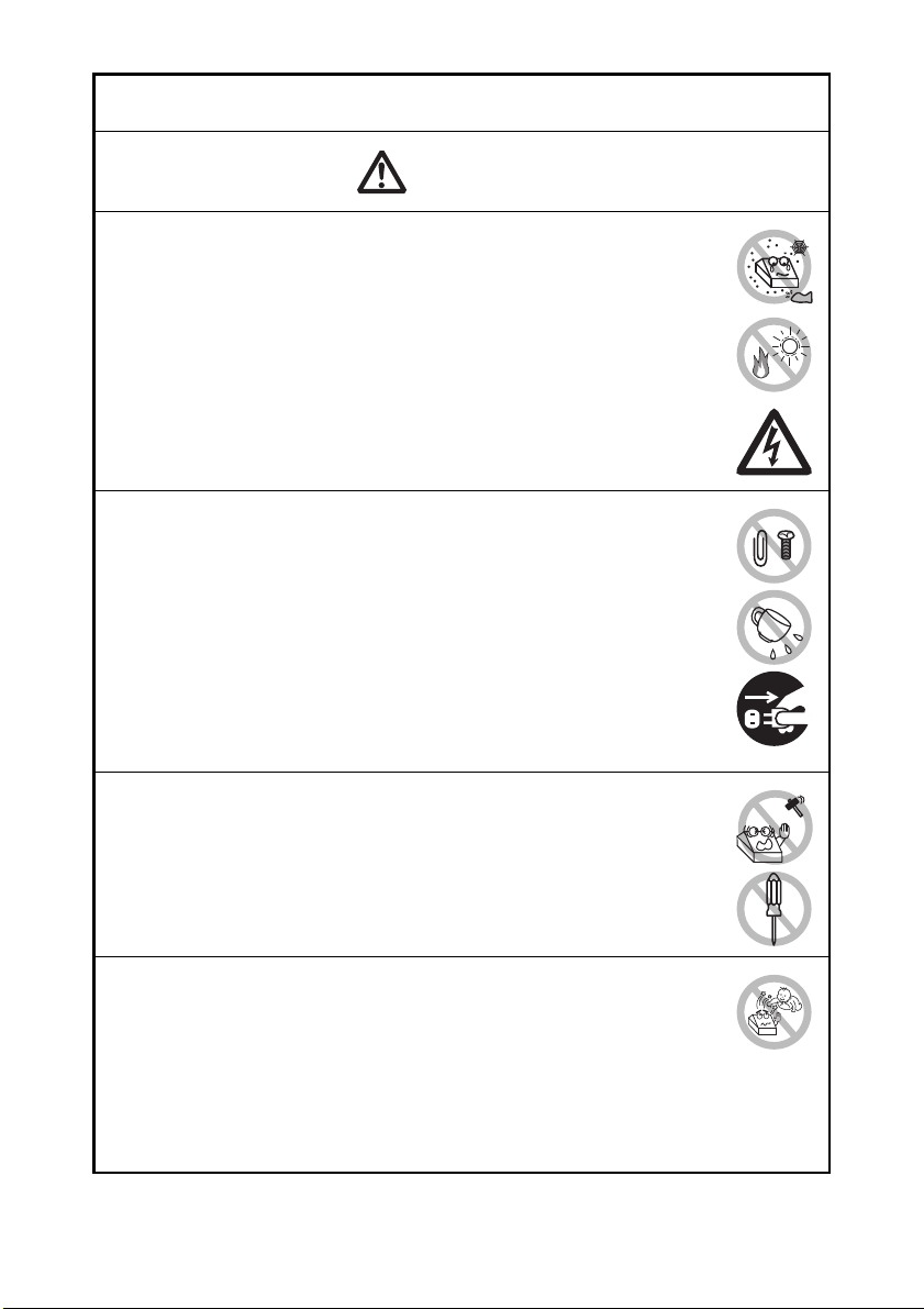
WARNING
Do not use or store this product in a place where it will be exposed to:
* Flames or moist air.
* Direct sunlight.
* Hot airflow or radiation from a heating device.
* Salty air or corrosive gases.
* Ill-ventilated atmosphere.
* Chemical reactions in a laboratory.
* Airborne oil, steel particles, or dust.
* Static electricity or strong magnetic fields.
• Neglecting these warnings may result in printer failure, overheating,
emission of smoke, fire, or electric shock.
Do not drop any foreign object nor spill liquid into the printer. Do not
place any object on the printer either.
Do not drop any metallic object such as paper clips, pins or screws
into the printer.
Do not place a flower vase, pot, or anything containing water on the
printer.
Do not spill coffee, soft drinks, or any other liquid into the printer.
Do not spray insecticide or any other chemical liquid over the printer.
• Dropping a metallic foreign object into the printer, may cause printer
failure, fire, or electric shock. Should it occur, immediately turn the
printer off, unplug it from the supply outlet, and call your local Citizen
Systems dealer.
Do not handle the printer in the following ways:
Do not subject the printer to strong impacts or hard jolts (e.g., being
stepped on, dropped or struck).
Never attempt to disassemble or modify the printer.
• Neglecting to handle properly may result in printer failure,
overheating, emission of smoke, fire, or electric shock.
Install, use, or store the printer out of the reach of children.
• Electric appliances could cause an unexpected injury or accident if
they are handled or used improperly.
• Keep the power cord and signal cables out of the reach of children.
Also children should not be allowed to gain access to any internal
part of the printer.
• The plastic bag the printer came in must be disposed of properly or
kept away from children. Wearing it over the head may lead to
suffocation.
—3—
Page 8
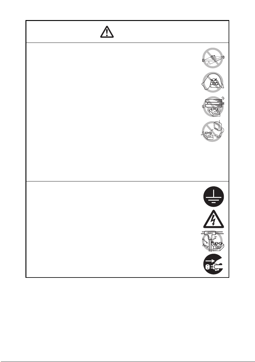
CAUTION
Do not use the printer under the following conditions.
Avoid locations subject to vibration or instability.
Avoid locations where the printer is not level.
• The printer may fall and cause an injury.
• The quality of printing may deteriorate.
Do not obstruct the printer’s air vents.
Do not place anything on the printer.
Do not cover or wrap the printer in cloth or blankets.
• Doing so could cause heat to build up and deform the case or start a
fire.
Avoid using the printer near a radio or TV set or from supplying it from
the same electric outlet as these appliances.
Avoid using the printer interconnected with a cable or cord that has no
protection against noise. (For interconnections, use shielded or a
twisted pair of cables and ferrite cores, or other anti-noise devices.)
Avoid using the printer with a device that is a strong source of noise.
• The printer may have an adverse effect on nearby radio or TV
transmissions. There may also be cases when nearby electrical
appliances adversely influence the printer, causing data errors or
malfunction.
Installed in any orientation other than those specified.
• Malfunction, failure, or electric shock may result.
Connect the printer to a ground.
• Electric leakage may cause an electric shock.
Do not connect the printer’s ground to any of the following:
* Gas piping
• A gas explosion could result.
* Telephone line ground
* Lightning rod
• If lightning strikes a large surge of current may cause fire or
shock.
* Water pipes
• Plastic water pipes should not be used for grounding. (Those
Before connecting or disconnecting the grounding lead to or from the
approved by a Waterworks Department may be used.)
printer, always unplug it from the electric outlet.
—4—
Page 9
PRECAUTIONS IN HANDLING THE PRINTER
WARNING
Please observe the following precautions for power source and power
cord:
Do not plug or unplug the power cord with a wet hand.
Use the printer only at the specified supply voltage and frequency.
Use only the specified AC adapter with the printer.
Check to make sure that the supply outlet from which the printer is
powered has a sufficient capacity.
Do not supply the printer from a power strip or current tap shared with
other appliances.
Do not plug the power cord into an electric outlet with dust or debris
left on the plug.
Do not use a deformed or damaged power cord.
Do not move the printer while its power is on.
• Neglecting to handle it properly may result in printer failure, emission
of smoke, fire, or electric shock.
• An overload may cause the power cord to overheat, catch fire, or the
circuit breaker to trip.
Do not allow anything to rest on the power cord. Do not place the
printer where the power cord may be stepped on.
Do not use or carry the printer with its power cord bent, twisted, or
pulled.
Do not attempt to modify the power cord unnecessarily.
Do not place the power cord near any heating device.
• Neglecting these cautions may cause wires or insulation to break,
which could result in electric leakage, electric shock, or printer failure.
If the power cord sustains damage, contact your Citizen Systems
dealer.
Do not leave things around the electric outlet.
Supply power to the printer from a convenient electric outlet, readily
accessible in an emergency.
• Pull the plug to immediately shut it down in an emergency.
Insert the power plug fully into the outlet.
If the printer will not be used for a long time, disconnect it from its
electric outlet.
Hold the plug and connector when plugging or unplugging the power
cord or signal cable after turning off the printer and the appliance
connected to it.
—5—
Page 10
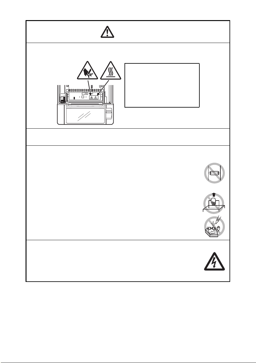
CAUTION
Caution label is attached in the position shown in the following figure. Carefully read
THIS LABEL INDICATES THE
RISK OF BURNS DUE TO THE
HIGH TEMPERATURE OF THE
PRINT HEAD AND A RISK OF
BEING CUT BY THE MANUAL
AND AUTO CUTTERS WHILE
THE PAPER COVER IS OPEN.
the handling precautions before using the printer.
Do not transport this printer with the paper roll inside.
• Printer failure or damage may occur.
To prevent possible malfunction or failure observe the following.
Do not open the paper cover during printing.
Avoid operating the printer without paper properly loaded.
Avoid the use of paper not complying with specifications.
• May result in poor print quality.
Avoid using torn pieces of paper or paper spliced with plastic adhesive
tape.
Avoid forcibly pulling already loaded paper by hand.
Avoid using a sharp pointed device to operate panel buttons.
Be sure to firmly insert the cable plugs into their mating sockets.
• A cross connection may damage the printer’s internal electronics or
the host system’s hardware.
Only use the printer with devices that have designated solenoid
specifications for the cash drawer interface connector.
• Neglecting this caution may result in malfunction or failure.
—6—
Page 11
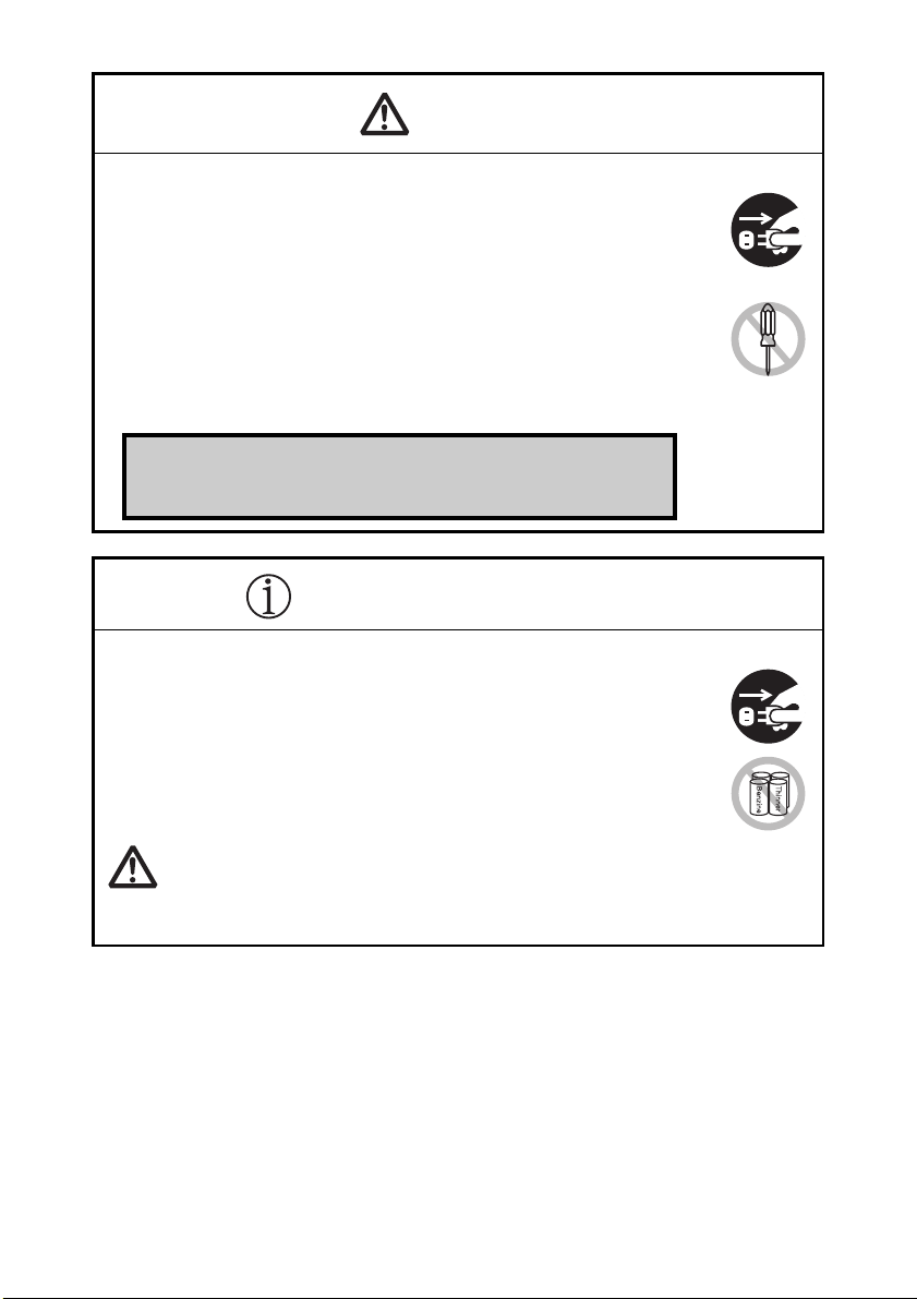
CAUTION
To prevent injury and printer failures from worsening, observe the following:
CAUTION
If the printer emits smoke, an odd smell, or unusual noise while
printing, immediately abort the current print session and
unplug the printer from the electric outlet.
Visit the following site to get documentation, drivers, utilities, and other
information.
http://www.citizen-systems.co.jp/english/support/index.html
While the paper cover is open, be careful to not touch the manual
cutter that is in the paper eject slot.
Do not touch the printing surface of the thermal head.
Do not touch any of the moving parts (e.g., paper cutter, gears, active
electric parts) while the printer is working.
In case of trouble do not attempt to repair the printer. Ask Citizen
Systems service for repair.
Be careful that the covers do not pinch your hands or fingers.
Be careful of the sharp edges on the printer. Do not allow them to
injure you or damage property.
• May result in electric shock, burn, or injury.
DAILY MAINTENANCE
Observe the following precautions for daily maintenance.
When cleaning the printer, always turn it off and unplug it from the
electric outlet.
Use a soft, dry cloth for cleaning the surface of the printer case.
For severe stains, use a soft cloth slightly dampened with water.
Never use organic cleaning solvent such as alcohol, paint thinner,
trichloroethylene, benzene, or ketone. Never use a chemically
processed cleaning cloth.
To remove paper dust, use a soft brush.
• The thermal head is at a dangerously high temperature immediately after printing.
Allow it to cool off before starting maintenance work.
—7—
Page 12

THE TABLE OF CONTENTS
1. GENERAL OUTLINE ....................................................................9
1.1 Features........................................................................................... 9
1.2 Unpacking...................................................................................... 10
1.3 Model Classification ...................................................................... 10
1.4 Basic Specifications....................................................................... 11
2. EXPLANATION OF PRINTER PARTS .......................................13
2.1 Printer Appearance ........................................................................ 13
2.2 Inside the Paper Cover .................................................................. 16
2.3 Other Built-in Functions................................................................. 18
3. SETUP ........................................................................................20
3.1 Connecting the AC Power Cord .................................................... 20
3.2 Connecting Interface Cables ......................................................... 21
3.3 Bluetooth Interface Board ............................................................. 23
3.4 Ethernet (LAN) Interface Board ..................................................... 25
3.5 Wireless LAN Interface Board ....................................................... 28
3.6 Connecting the Cash Drawer ........................................................ 32
3.7 Precautions for Installing the Printer ............................................. 34
3.8 Partition for Paper Roll................................................................... 35
3.9 Setting the DIP Switch on the Serial Interface Board.................... 36
3.10 Adjusting the Paper Near-end Sensor.......................................... 37
3.11 Loading Paper .............................................................................. 38
3.12 Calibrating the Paper Sensor ....................................................... 39
3.13 Selecting a Paper Type ................................................................ 42
3.14 Attaching the Power Switch Cover.............................................. 43
3.15 Attaching the Interface Cover...................................................... 43
3.16 Removing the Interface Cover..................................................... 44
3.17 Installing a Driver ......................................................................... 44
3.18 Precautions for Creating Applications and Practical
Operations ................................................................................... 45
4. MAINTENANCE AND TROUBLESHOOTING........................... 46
4.1 Periodic Cleaning ........................................................................... 46
4.2 Clearing a Cutter Lock (1) .............................................................. 47
4.3 Clearing a Cutter Lock (2) .............................................................. 48
4.4 Function Test Mode ...................................................................... 49
4.5 Key Lock Function ......................................................................... 51
4.6 Hexadecimal Dump Printing .......................................................... 52
4.7 Error Messages ............................................................................. 53
4.8 Paper Jams.................................................................................... 55
4.9 Serial Interface Operation Precautions .......................................... 55
5. OTHER .......................................................................................56
5.1 External Views and Dimensions .................................................... 56
5.2 Printing Paper ................................................................................ 57
5.3 Manual Setting of Memory Switches............................................ 60
—8—
Page 13

1. GENERAL OUTLINE
The CT-S801II line thermal printer series is designed for use with a broad array
of terminal equipment including data, POS, and kitchen terminals.
These printers have extensive features so they can be used in a wide range of
applications.
1.1 Features
Prints at speeds up to 300 mm/sec
Design so compact it can be installed anywhere (maximum 3-inch (83-mm)
paper roll size)
Choose from two models with either 3-inch (83/80 mm) or 2-inch (60/58 mm)
wide paper rolls
Built-in power supply or AC adapter types available
Printer status and errors indicated by LCD, LED, and a buzzer
LCD and four buttons make it easy to change settings
Equipped with a fast and quiet cutter
Easy to clear cutter jams
USB power supply OFF
Interchangeable interface
Built-in cash drawer kick-out interface
Memory switches make customization possible
Store user-defined characters and logos on user memory
Barcode and 2D barcode printing supported
16 level greyscale and clear printing
Paper saving functions
Japanese Kanji, Chinese(simplified and traditional) and Hangul supported
Driver and utility software included
Apple MFi certified Bluetooth communication support (Bluetooth model)
Some models support label paper and/or black mark paper
—9—
Page 14
Notes:
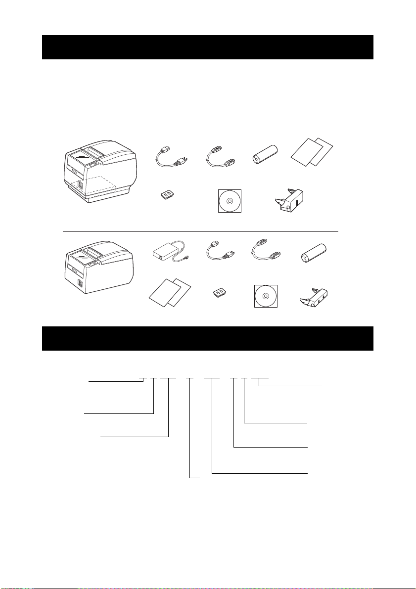
1.2 Unpacking
Notes:
CT-S801IIS
(Built-in power supply type)
36AD3/37AD3 AC adapter built in
AC power cord
Power switch cover
USB cable
Quick Start
Guide
CT-S801IIA
(AC adapter type)
AC adapter
(36AD2/37AD5)
AC power
cord
Quick Start
Guide
CD-ROM
USB cable
Sample
paper roll
Interface cover
Interface coverCD-ROM
Sample
paper roll
Power switch
cover
CT - S801IIS 3 RS E - BK - P L M1
Power supply
DC:No power source
S: Built-in power supply type
A: AC adapter type
Interface
PA: Parallel
RS: Serial RS-232C
UB: USB only
UH: USB with hub
ET: Ethernet (standard type)
ES: Ethernet (multi-function type)
UP: Powered USB
BT: Bluetooth
WF: WiFi W5: WiFi(5.0GHz)
Market
*1
J: Japan E: Europe
U: North America
C: China
A: Asia/Oceania
Paper width
3: 3 inch (80/83 mm)
2: 2 inch (58/60 mm)
Body case color
WH: Cool white
BK: Black
Label
:No
L: Label printing
BM sensor
:No
M1: Left side
M2: Right
side
*2
PNE sensor
:No
P: PNE sensor
Make sure the following items are included with your printer.
Printer: 1
Interface cover: 1
AC power cord: 1
Power switch cover: 1
Sample paper roll: 1 roll
CD-ROM: 1
Quick Start Guide: 2
AC adapter
USB cable
*1: CT-S801IIA only
*2: USB interface types only
In designated markets
*1:1
*2:1
1.3 Model Classification
Model numbers indicate printer features according to the following system.
Certain combinations may not be available. Check with Citizen beforehand.
*1: AC power cord, serial I/F screw, firmware and other specifications vary according to markets.
*2: 3-inch type only
—10—
Page 15
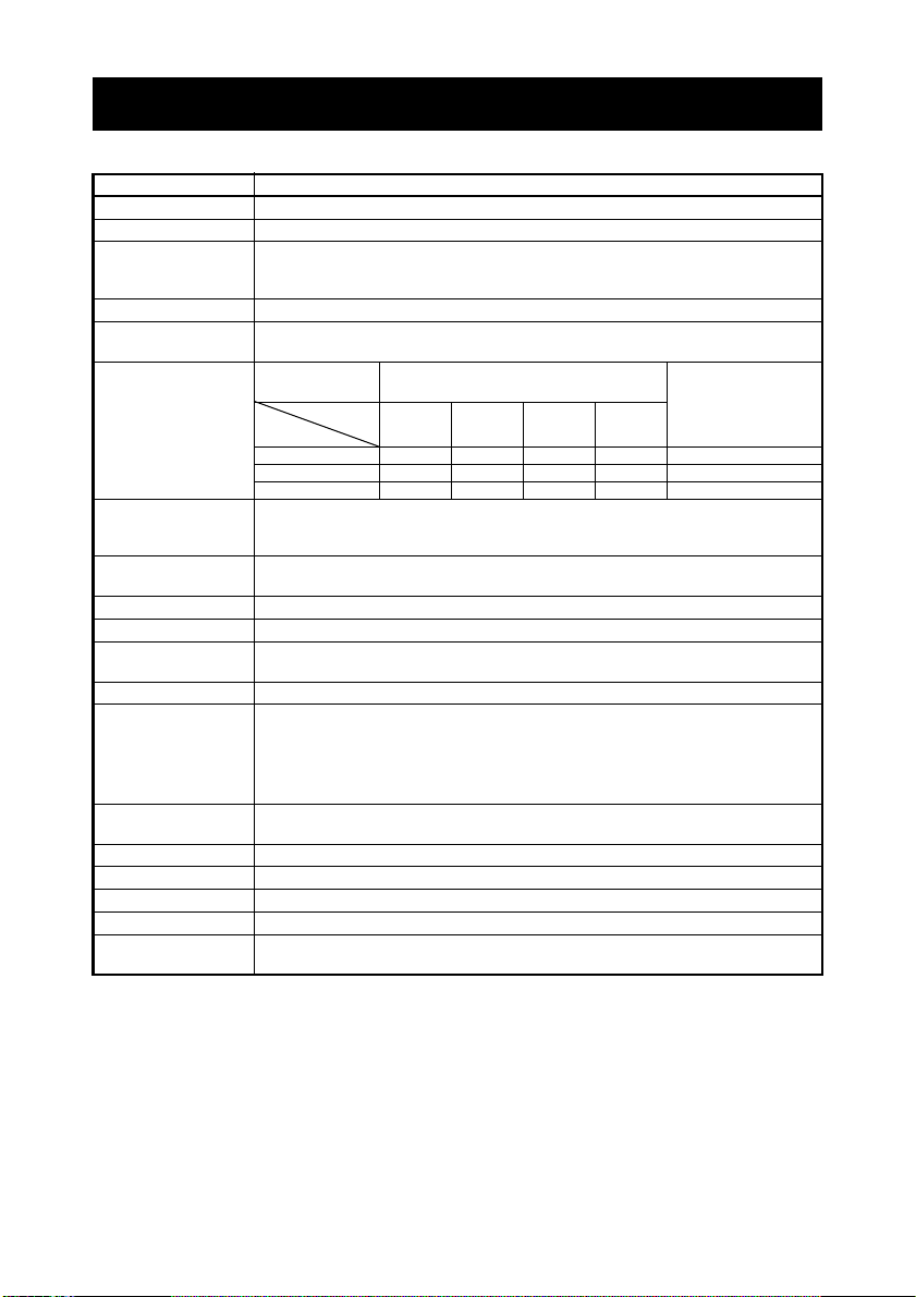
1.4 Basic Specifications
+0-1+0-1+0-1+0
-1
Item Specifications
Model CT-S801II
Print method Line thermal dot print method
Print width
Dot density 8 8 dots/mm (203 dpi)
Print speed 300 mm/s (fastest, print density 100%, 2400 dot-lines/s)
Number of print
columns
Character size
Character type Alphanumeric, international, PC437/850/852/857/858/860/863/864/865/866,
Liquid crystal display (LCD)
User memory 384 KB (capable of storing user-defined characters and logos)
Bar code types UPC-A/E, JAN (EAN) 13/8 columns, ITF, CODE39, CODE128, CODABAR (NW-7),
Line spacing 4.23 mm (1/6 inch) (changeable using commands)
Paper roll
Interface Serial (RS-232C compliant), parallel (IEEE 1284 compliant), USB, USB with hub,
Cash drawer kick-out Supports 2 cash drawers
Buffer size 4 k bytes/45 bytes
Supply voltage DC 24 V 5%
Power consumption Approximately 45 W (normal printing), 3 W (standby)
AC adapter
(36AD2/3, 37AD3/5)
*1 80 mm/640 dots, 72 mm/576 dots, 64 mm/512 dots, 54.5 mm/436 dots,
54 mm/432 dots, 52.5 mm/420 dots, 48 mm/384 dots, 45 mm/360 dots,
48.75 mm/390 dots, 68.25 mm/546 dots
150 mm/sec (1200 dot lines/sec) (for label specifications)
*2
—
Paper width
Font
Font A 53483635 1224
Font B 71644846 9 24
*3 Font A: 1.50 3.00 mm
Font C 80725452 8 16
Font B: 1.13 3.00 mm
Maximum number of characters
(columns)
83 mm 80 mm 60 mm 58 mm
Dot configuration
Font C: 1.00 2.00 mm
WPC1252, katakana, ThaiCode 11/18 (1Pass/3Pass), TCVN-3
128 32 dots STN liquid crystal, white/red LED backlight
CODE93, PDF417, QR Code, GS1-DataBar
Paper roll: 83 mm/80 mm/60 mm/58 mm maximum 83 mm
Paper thickness: 65 to 75 m (core tube diameter: inner 12 mm/outer 18 mm)
75 to 85 m (core tube diameter: inner 25.4 mm/outer 32 mm)
85 to 150 m (core tube diameter: inner 25.4 mm/outer 32 mm:
Supported by label-printing models only)
Ethernet, Powered USB, Bluetooth(3.0), wireless LAN (802.11b/g or 802.11a/b/g/n)
*4
Rated input: AC 100 to 240 V, 50/60 Hz, 150 VA
Rated output: DC 24 V, 2.1 A
(dots)
—11—
Page 16

Notes:
Item Specifications
Weight CT-S801IIS: Approx. 2 kg, CT-S801IIA: Approx. 1.6 kg
Outside dimensions CT-S801IIS: 145 (W) 192 (D) 148 (H) mm
Operating temperature
CT-S801IIA: 145 (W) 192 (D) 120 (H) mm
5 to 45°C, 10 to 90% RH (no condensation)
and humidity
Storage temperature
and humidity
Reliability Print head life: 150 km, 200 million pulses (at normal temperature/humidity,
-20 to 60°C, 10 to 90% RH (no condensation)
using recommended paper and paper thickness)
Auto cutter life: 2 million cuts (at normal temperature/humidity, using
recommended paper and paper thickness)
Safety standard
*1: When paper width is 83, 80, 60, or 58 mm.
*2: The number of printable columns is selected using a memory switch.
The numbers of columns noted in this table refer to typical models. The number of columns
varies depending on specifications.
*3: Characters appear small because the dimensions include a blank area surrounding each character.
*4: The 36AD2/37AD5 is the AC adapter packaged as an accessory with the CT-S801IIA.
The 36AD3/37AD3 is the AC adapter built in to the CT-S801IIS.
*5: Compliant if the Citizen Systems AC adapter (36AD2/3, 37AD3/5) is used.
*5 UL, C-UL, FCC Class A, TÜV-Bauart, CE Marking
—12—
Page 17
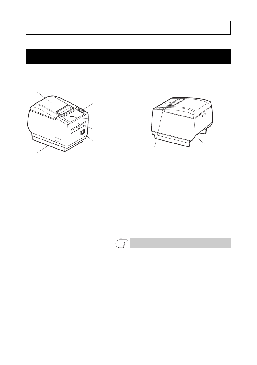
2. EXPLANATION OF PRINTER PARTS
Paper cover
Rear connectors
Maintenance cover
Power switch
Operation panel
Cover open lever
(Front view) (Rear view)
Front cover
Front cover
release button
2.1 Printer Appearance
Names of parts
Paper cover
Open to load paper.
(A label guide is attached to the paper cover of label-printing models.)
Cover open lever
Use this lever to open the paper cover.
Front cover
Open and close this cover to clear a cutter lock.
Front cover release button
Press this button to open the front cover.
Power switch
Press this switch to turn the power on or off.
Maintenance cover
Not applicable for this product.
Not used. Do not remove.
—13—
Refer to 4.3 Clearing a Cutter Lock (2)
Page 18
CAUTION
Do not open the maintenance cover.
LCD
LED Button 1 to Button 4
LOCK icon
Button 4 (MENU)
Button 1 (FEED)
PAPER LOW
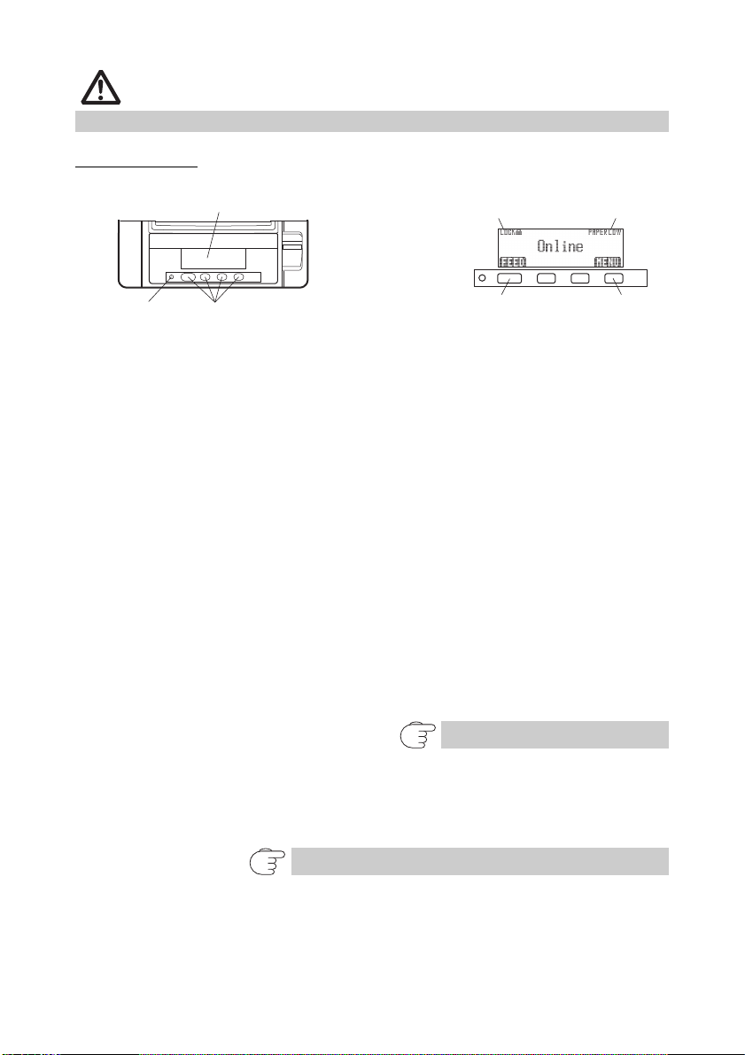
Operation panel
Examples are shown in the diagram of the LCD above on the right.
LCD
Indicates the printer’s status, button names, types of errors, and messages.
LED
Lights green when the power is on, turns off when the power is off.
Flashes green when receiving data.
Lights red in special modes and in case of errors.
Lights orange when paper is low (paper near-end) or the print head is hot.
Button 1 to Button 4
Functions assigned to these buttons vary depending on the active mode. The
buttons are called button 1, button 2, button 3, and button 4 in order from left
to right.
FEED button
Press this button to feed paper.
To release a cutter lock, remove the cause of the lock, close the paper cover,
and then press the FEED button.
Refer to 4.7 Error Messages
MENU button
Press and hold this button (for at least two seconds) to access the memory
switch setting mode.
Refer to 5.3 Manual Setting of Memory Switches
PAPER LOW
Appears when the paper roll is near its end.
—14—
Page 19
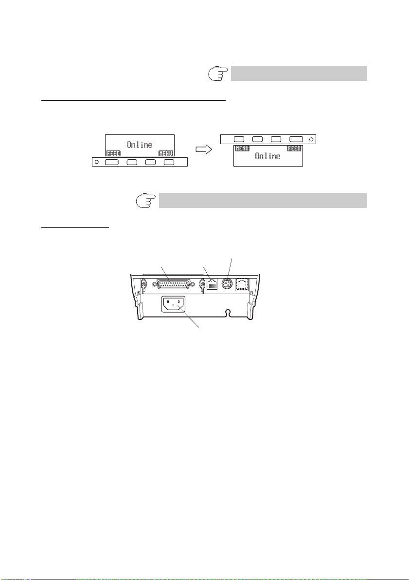
LOCK icon
Inverted image
Interface connector
(serial, parallel, USB, etc.)
Cash drawer
kick-out
connector
Power connector (AC adapter type)
AC inlet (built-in power supply type)
This icon indicates that the MENU button is inoperative.
Refer to 4.5 Key Lock Function
LCD in the vertical or wall mounted position
You can change the memory switch settings to invert the LCD if the printer is
used in a vertical position or installed on a wall.
Refer to 5.3 Manual Setting of Memory Switches
Rear connectors
Interface connector (serial, parallel, USB, etc.)
Connects to the interface cable.
The serial interface board is equipped with a DIP switch.
Cash drawer kick-out connector
Connects to the cable from the cash drawer.
Power connector (AC adapter type)
Connects to the AC adapter cable.
AC inlet (built-in power supply type)
Connects to the AC power cord.
—15—
Page 20
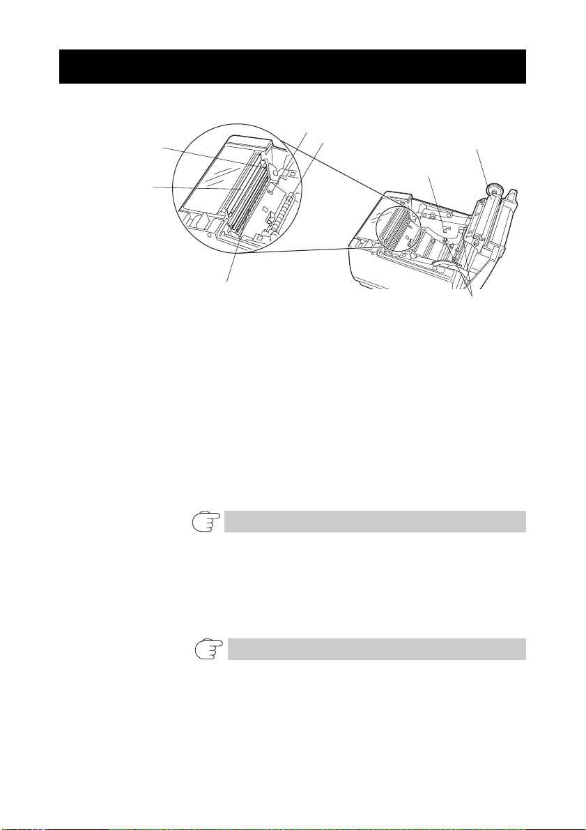
2.2 Inside the Paper Cover
Platen
Button to change paper
near-end sensor
Print head (thermal)
Auto cutter
Paper near-end sensor
(PNE sensor)
Paper-end sensor
(PE sensor)
Manual cutter
Paper damper
Platen
Feeds the paper.
Do not remove the platen except to do maintenance.
Paper near-end sensor (PNE sensor)
Detects when the paper is near the end of the roll. Adjust the position of the
sensor to determine when it detects the end of the paper is near.
Button to change paper near-end sensor
Change the position of the paper near-end sensor to match the paper being
used.
Manual cutter
For cutting the paper manually when printing is finished.
Auto cutter
Automatically cuts the paper when printing is finished.
Print head (thermal)
Prints characters and graphic data on paper (paper rolls).
Paper end sensor (PE sensor)
Detects when there is no paper. Printing stops when this sensor detects there
is no paper.
Refer to 3.10 Adjusting the Paper Near-end Sensor
Refer to 5.3 Manual Setting of Memory Switches
—16—
Page 21
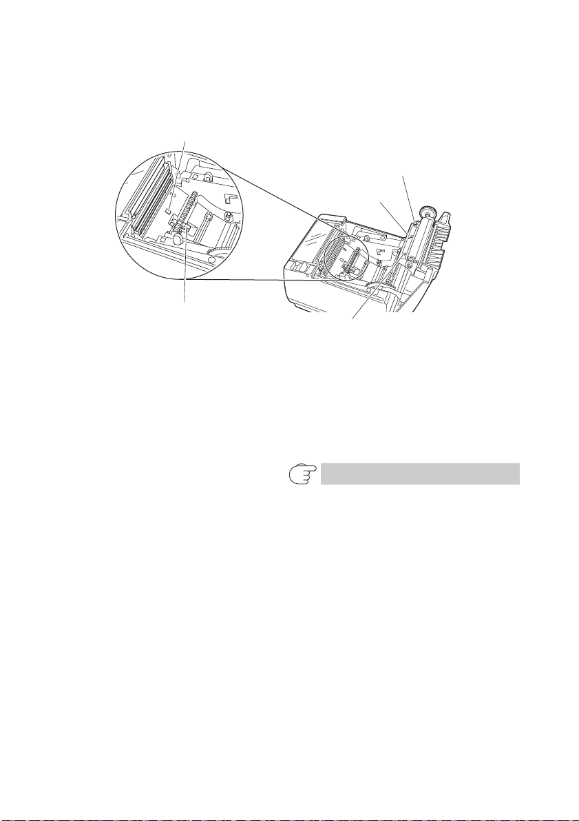
Paper damper
Paper damper stopper
Label sensor
Black mark sensor (M1)
Label sensor
Black mark sensor (M2)
Assists paper feed.
The components in the figure below are used in label-printing models and black
mark models.
Paper damper stopper
Used to lock the paper damper.
Black mark sensor
Detects black marks on black mark paper.
The sensor position is either M1 or M2, depending on the model
classification.
Label sensor
Measures the length of label paper.
Refer to 1.3 Model Classification
—17—
Page 22

2.3 Other Built-in Functions
CAUTION
Buzzer
Buzzes when errors occur or when operations or command operations are
performed.
Refer to 4.7 Error Messages
User memory
You can save user-defined logo and character data in this memory. Data
remains stored in this memory even if the printer is turned off. For
information on how to save data, refer to the Command Reference.
Memory switch
Setting of various kinds of functions can be stored in memory. Settings
remain stored in the memory even if the printer is turned off.
USB power supply OFF (When memory switch MSW6-3 is set to ON)
When the printer is connected to a PC by USB, turning off PC power or terminating
the USB connection causes printer USB power to turn off three seconds later.
This mode is canceled when the PC is turned back on or when a USB connection
is established.
The POWER LED is unlit when USB power supply is OFF, and the power OFF state cannot
be identified.
Pressing POWER while USB power is off does not turn on power immediately. After a
while, USB power supply OFF is canceled and pressing POWER turns on power normally.
Paper saving functions
Memory switches MSW8-3 through MSW8-5 can be used to configure
the settings below, which save paper.
•Top margin suppression
The printer back feeds the paper before printing which reduces the blank space
at the top edge of the paper.
The back feed amount can be specified.
•Line gap reduce
Automatically compresses the linefeed amount between lines. The compression
ratio can be specified.
•Text compression vertical/horizontal
Makes the print size smaller.
The compression amount is specified by a combination of vertical and horizontal
compression ratios.
—18—
Page 23

Auto side shift (MSW8-6)
CAUTION
This function dissipates heat load during frequent heat generation by a vertical
ruled line or other specific head heating element.
If no data is received within 15 seconds after each cut or print, the print position is
automatically slid N* dots to the right. The original print position is returned to at
the next slide timing.
* N is the MSW8-6 setting value.
Before configuring the top margin suppression setting, first remove any partially cut paper
from the printer. Failure to do so can cause the cut paper to be torn off by the next print
operation, which can cause printer trouble.
Note the following precautions when using text compression.
• Compressed text is more difficult to read than the original text.
• Horizontally compressing text also makes the print range smaller, so the number of
print lines does not change. Pay close attention to the print range when using
narrow paper.
• Do not use compressed text when printing a bar code. Doing so may make the bar
code unreadable.
If the right margin is too narrow, this may result in some print characters being cut off. This
function is disabled under initial settings. To enable this function, use MSW8-6 to specify an
appropriate value for the maximum slide amount.
—19—
Page 24
3. SETUP
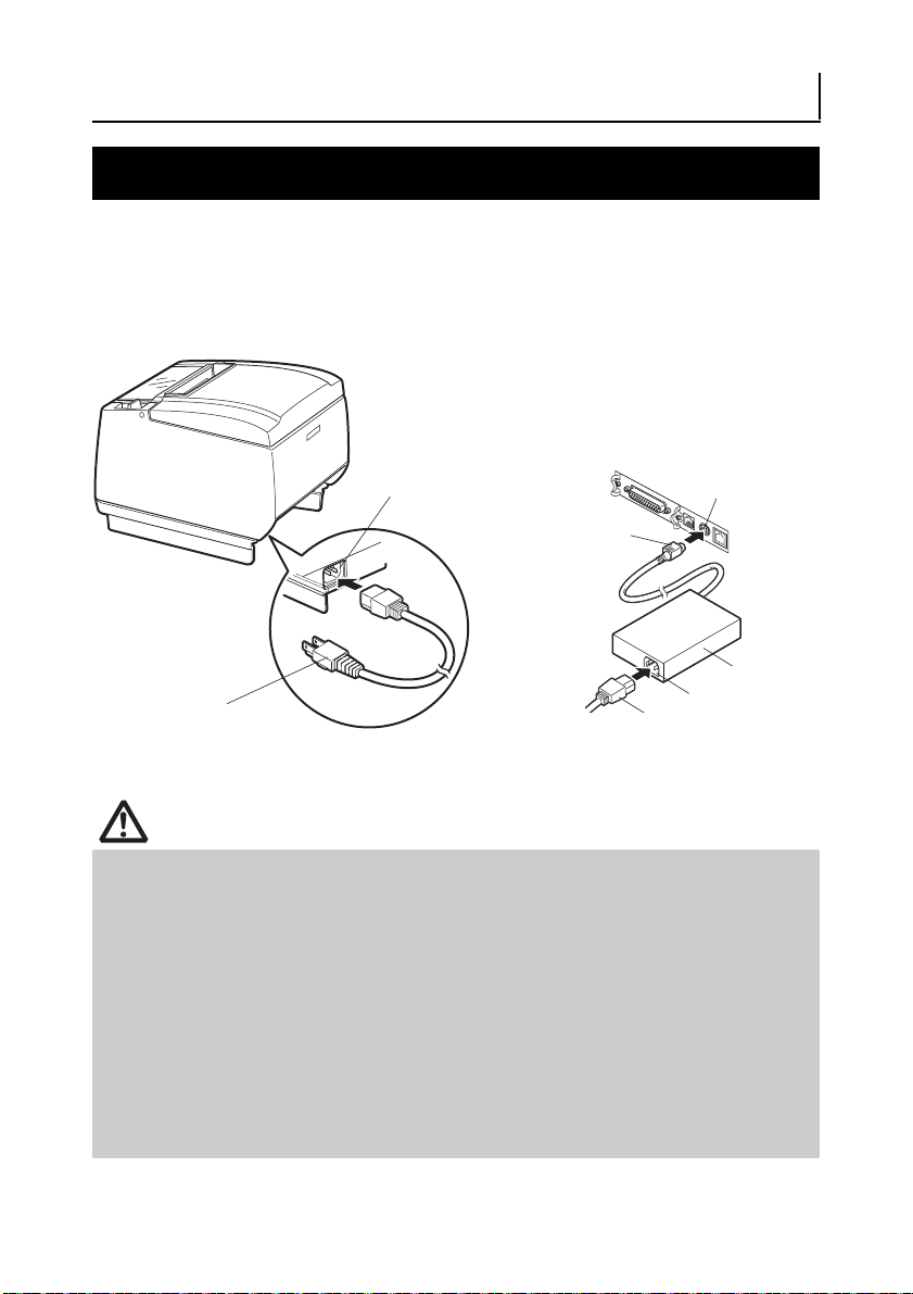
CAUTION
AC inlet
AC power cord
Power connector
AC inlet
AC adapter
AC power cord
Cable connector
Built-in power supply type
AC adapter type
3.1 Connecting the AC Power Cord
1. Turn off the power.
2. For the built-in power type printer, connect the AC power cord to the AC inlet, and
insert the plug into an electric outlet.
For the AC adapter type printer, connect the cable connector of the AC adapter to
the power connector. Next, connect the AC power cord to the AC inlet, and insert
the plug into an electric outlet.
Use only an AC adapter that complies with the specified ratings.
Always hold the AC adapter’s cable connector by the connector when removing or inserting
it.
Use an AC power source that does not also supply power to equipment that
generates electromagnetic noise.
Pulling on the AC power cord may damage it, cause a fire, electric shock, or break a
wire.
If a lightning storm is approaching, unplug the AC power cord from the electric outlet.
A lightning strike may cause a fire or electric shock.
Keep the AC power cord away from heat generating appliances. The insulation on the
AC power cord may melt and cause a fire or electric shock.
If the printer is not going to be used for a long time, unplug the AC power cord from
the electric outlet.
Place the AC power cord so that people do not trip on it.
—20—
Page 25
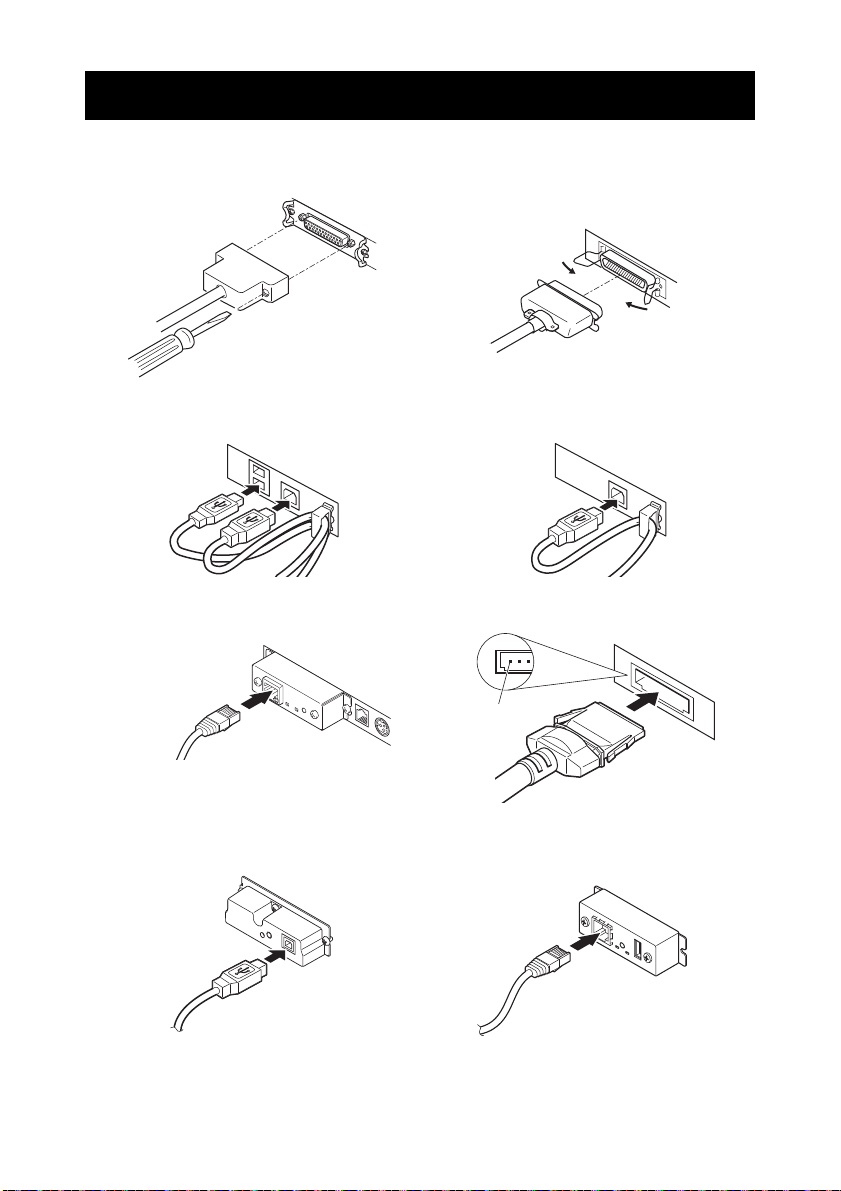
3.2 Connecting Interface Cables
Serial interface
Parallel interface
USB interface (hub type) USB interface
Ethernet interface Powered USB interface
Front view
Pin
Bluetooth + USB
Wireless LAN + LAN
1. Turn off the power.
2. Orient the interface cable correctly and insert it into the interface connector.
10/100BASE
—21—
Page 26
CAUTION
Always unplug the AC adapter from the printer before connecting the printer to a
CAUTION
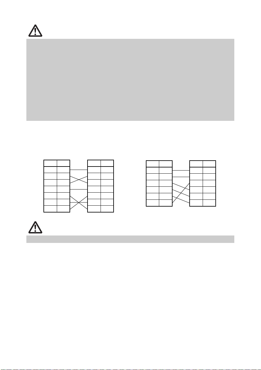
25-pin - 25-pin cable
PC Printer
Signal
Pin Pin
Signal
RXD 2 2 TXD
TXD 3 3 RXD
DTR 4 4 RTS
SG 5 6 DSR
DSR 6 7 SG
CTS 8 20 DTR
9-pin - 25-pin cable
PC Printer
Signal
Pin Pin
Signal
FG 1 1 FG
TXD 2 2 TXD
RXD 3 3 RXD
CTS 5 4 RTS
DSR 6 6 DSR
SG 7 7 SG
DTR 20 20 DTR
Powered USB interface. Failure to do so may damage the host PC. For information
about installing a Powered USB interface, contact your Citizen Systems dealer.
Check the orientation of the Powered USB cable connector before connecting it. Insert
it straight in so that the pins do not bend. Push it in until it clicks.
When disconnecting the cable, always hold the connector.
Be careful not to insert the USB interface cable into the cash drawer kick-out
connector.
To connect more than one printer to a single computer via a USB interface you must change
the serial number of the USB interface.
Hold the connector of the Ethernet interface cable perpendicular and straight when
connecting or disconnecting it. Doing it at an angle may cause the connector to
misconnect.
Use a serial interface cable with the connection layout shown below.
Place the interface cable so people do not trip on it.
—22—
Page 27
3.3 Bluetooth Interface Board
SwitchStatus LED
Bluetooth status LED
The LED on the Bluetooth interface board on the rear of the printer indicates the
status below.
Status Description LED Status
Detection
standby
(Discoverable)
Connection
standby
(Connectable)
iOS connection Data session unopened
Standing by for
detection and
connection
Standing by for
connection
Communicating iOS: data session
Error Error or settings being
opened
Other OS: connection
established and
communication in
progress
configured
Unlit
Pairing operation
You need to perform the operations below the first time you establish a Bluetooth
connection for Bluetooth data communication.
A: Detect Bluetooth devices
B: Configure pairing settings
A: Detecting Bluetooth devices
Confirm that Bluetooth is enabled on the host PC before searching for Bluetooth
devices.
This product will show up as "CT-S801II_XX"(XX is last 2 digits of unique BD address.)
when it is detected.
Select this product from among the detected devices.
Note: You can search for devices and change the names.
When memory switch MSW13-5 is set to "No Response" nothing is displayed by
device detection.
You can temporarily switch this setting to device detection (detect mode) by pushing
the switch on the Bluetooth interface board. Detect mode is exited when the
connection between the host PC is terminated.
—23—
Page 28

B: Configuring pairing settings
CAUTION
CAUTION
Normally, selecting the printer during device detection will transition directly to
pairing settings.
Some host PC configurations and models may not transition directly to pairing settings after
the printer is selected during device detection.
The operation required to configure pairing settings depends on whether SSP (secure
simple pairing) is enabled on the host PC.
If SSP is enabled on the host PC, pairing can be achieved without additional
operations.
If SSP is disabled on the host PC, you will be prompted to input a passkey.
Input the passkey as described below.
Passkey Last four digits of the address on the self test printout
(Letters A through F are uppercase)
Example: If the address is 01:23:45:67:89:AB
the passkey is 89AB.
If you delete paring information from the host PC without deleting the corresponding
pairing information on the printer, the printer may not show up if you detect devices
again with the host PC.
To delete printer pairing information, hold down the switch on the Bluetooth interface
board for two seconds or more.
Deleting pairing information on the printer will put the printer into discovery mode.
Auto reconnection
With iOS device Bluetooth communication, a connection between a paired iOS
device and the printer is not automatically restored after it is lost. However, when
auto reconnection is enabled, the printer tries to reconnect with an iOS device after
two-way communication is enabled and automatically restores the connection.
This function is enabled when shipped from the factory. (MSW13-6)
Auto reconnection can take some time to connect when the host is not an iOS device.
Even if the partner device is an iOS device, the conditions below can interfere with the auto
reconnection function.
• When you want Bluetooth communication to cut off after printing is complete
• When there are multiple iOS devices printing on the same printer
Under such conditions, disable auto reconnection.
Enabling and disabling auto reconnection
To change the setting of this feature, the following method is provided.
Press the FEED button 3 times during self test -> Auto reconnect = Valid
Press the FEED button 4 times during self test -> Auto reconnect = Invalid
At the end of self test, new setting will be printed as Auto reconnect [Valid] or [Invalid]
Refer to 4.4 Function Test Mode
—24—
Page 29
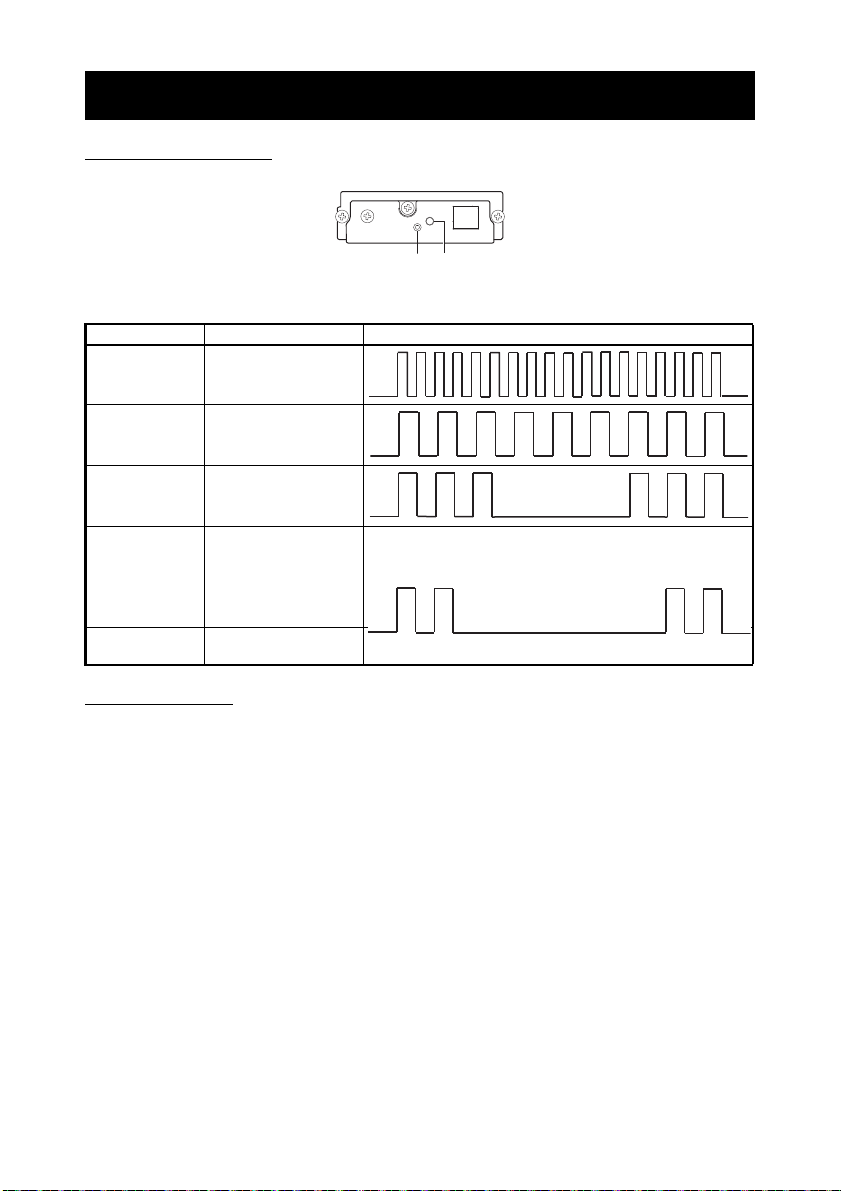
3.4 Ethernet (LAN) Interface Board
CAUTION
Panel button
This section provides an overview of the Ethernet (LAN) interface board. For details
about this board, refer to the separate manual.
Panel button operation
Board operations are performed using the panel button on the Ethernet board. You
can use the button to print setup information and to return the board to its factory
settings.
10/100BASE
Printing network setup information
Press the panel button.
Entering setting mode
Hold down the panel button. A buzzer* will sound once to indicate that setting mode
has been entered.
• You can use setting mode to read factory settings and to print firmware information.
• If you do not perform any operation for three seconds while in setting mode, a buzzer* will
sound once to indicate the board has returned to normal mode.
* Depending on settings, the buzzer may not sound.
Returning to factory settings
Enter the board setting mode, and then hold down the panel button. This returns
the board to its factory settings.
The board will automatically restart after this operation is complete.
If settings are configured to obtain an IP address from a DHCP server automatically, the
new IP address may be different from the previous one.
—25—
Page 30
LED Functions
10/100BASE
12
3
The tables below explain how to interpret LED indications.
1. Network transmission speed
Transmission speed LED (green)
100Mbps Lit
10Mbps/Not connected Unlit
2. Network status
Status LED (yellow)
Connected Lit
Not connected Unlit
Data transmission in
progress
Flashing
3. Board status
Status LED (green) LED (red) Description
No printer connection Unlit — Board is not connected with a printer.
Connecting with printer Lit — Board is connected with a printer.
No network connection — Unlit Board is not connected with a network.
Getting IP address — Flashing
Connected with network — Lit Network connection complete.
Resource error Alternate flashing
System error Alternate flashing
(0.5-second cycle)
(0.1-second cycle)
(0.5-second
cycle)
Getting an IP address from the DHCP
server.
Board is unable to operate normally.
Board is unable to operate normally.
—26—
Page 31

Changing network settings
You can use a web browser to access a special settings page to check and change
board settings.
Accessing the special settings page
1. Use a web browser to access the URL of the special settings page. Specify the IP
address assigned to the printer as the URL. (Example: For an IP address of
169.254.1.10, input: http://169.254.1.10.)
2. This displays the special settings page menu page.
3. Select "Print server configuration" to display the setting screen.
For details about settings, refer to the separate manual.
—27—
Page 32

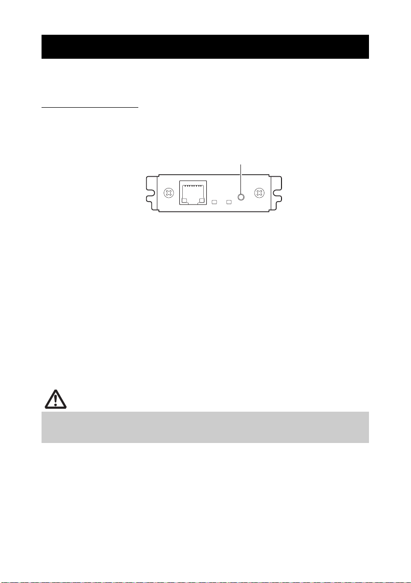
3.5 Wireless LAN Interface Board
CAUTION
Panel button
USB port
This section provides an overview of the wireless LAN interface board. For details
about this board, refer to the separate manual.
Connecting USB dongle
Connect the USB WiFi dongle that comes with the wireless LAN interface board to
the USB port connector.
To improve signal quality, you can also use a USB extension cable and adjust the
position of the dongle.
Panel button operation
Board operations are performed using the panel button on the rear of the LAN board.
Enabling wireless LAN connection
Turn on the printer. Operation of this board will start about 20 seconds later.
Printing wireless LAN setup information
Press the panel button.
Entering setting mode
Hold down the panel button. A buzzer* will sound once to indicate that setting
mode has been entered.
• You can use setting mode to read factory settings.
• If you do not perform any operation for three seconds while in setting mode, a buzzer* will
sound once to indicate the board has returned to normal mode.
* Depending on the printer model and settings, the buzzer may not sound.
Returning to factory settings
Enter the board setting mode, and then hold down the panel button. This returns
the board to its factory settings.
The board will automatically restart after this operation is complete. After clearing settings,
you will need to re-configure wireless LAN settings.
—28—
Page 33

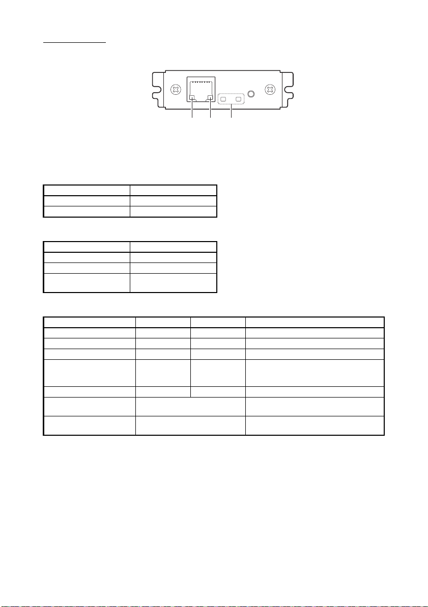
LED Functions
12 3
The tables below explain how to interpret LED indications.
1. Wired LAN transmission speed
Transmission speed LED (green)
100Mbps Lit
10Mbps/Not connected Unlit
2. Wired LAN connection/transmission status
Connection status LED (yellow)
Connected Lit
Not connected Unlit
Data transmission in
progress
Flashing
3. Wired/Wireless LAN status
Connection status LED (green) LED (red) Description
No printer connection Unlit — Board is not connected with a printer.
Printer
connection
Resource error Alternate flashing
System error Alternate flashing
No network
connection
Connected by
wired LAN
Wired LAN
operation
Connected by
wireless LAN
Wireless LAN
operation
Lit Unlit Board is connected with a printer.
Lit Flashing
Lit Lit Network operation being performed over
Flashing
(2-second cycle)
Flashing
(2-second cycle)
(0.2-second cycle)
(1-second cycle)
Flashing
(1-second cycle)
(1-second cycle)
Lit Network operation being performed over
Getting an IP address from the DHCP
server over wired LAN.
wired LAN.
Connecting to an access point or getting
an IP address from the DHCP server over
wireless LAN.
wireless LAN.
Board is unable to operate normally.
Board is unable to operate normally.
—29—
Page 34

Web Manager
The wireless LAN interface board has a Web Manager function that can be used to
connect to the board with a web browser and change board settings.
Starting up Web Manager
1. Start up a web browser.
2. In the address field, input the board's IP address and then press [Enter].
HOME Screen
This is the Web manager home screen.
Here, press the [CONFIG] button.
—30—
Page 35

CONFIG Screen
This will display the Login dialog box shown below. Log in as an administrator and
then configure wireless LAN interface board settings.
User Name
Input a board administrator user name. (Initial setting: admin)
Password
Input the administrator user password. (Initial setting: admin)
[Login] button
After inputting an administrator user name and password, click the [Login] button.
This displays the setting screen.
For details about settings, refer to the separate manual.
—31—
Page 36

3.6 Connecting the Cash Drawer
CAUTION
Cash drawer kick-out
connector
Cash drawer kick-out cable
connector
Ground wire
Screw for ground
wire
1. Turn off the power.
2. Confirm the orientation of the cash drawer kick-out cable connector and connect it
to the cash drawer kick-out connector at the back of the printer.
3. Remove the screw for the ground wire.
4. Screw the cash drawer’s ground wire to the body of the printer.
Connect only the cash drawer kick-out cable connector to the cash drawer kick-out
connector. (Do not connect a telephone line.)
Signals cannot be output from the cash drawer kick-out connector while printing.
—32—
Page 37

(1) Connector pin configuration
CAUTION
Cash drawer kick-out connector
Cash drawer open/
close switch
Shielded
Cash drawer Printer
No. Signal Function
1 FG Frame ground Connector used:
2 DRAWER1 Cash drawer 1 drive signal
3 DRSW Cash drawer switch input
4 VDR Cash drawer drive power supply
5 DRAWER2 Cash drawer 2 drive signal
6 GND Signal ground (common ground on
circuits)
TM5RJ3-66 (Hirose) or
equivalent
Applicable connector:
TM3P-66P (Hirose) or
equivalent
(2) Electric characteristics
1) Drive voltage: 24 VDC
2) Drive current: Approx. 1 A max. (not to exceed 510 ms.)
3) DRSW signal: Signal levels: “L” = 0 to 0.8 V, “H” = 2 to 3.3 V
(3) DRSW signal
DRSW signal status can be tested with the DLE+EOT, GS+a, or GS+r
command or at pin 34 on the parallel interface port.
(4) Drive circuit
Cash drawers 1 and 2 cannot be operated at the same time.
The solenoid used for the cash drawer should be 24 or more. Do not allow the
electric current to exceed 1 A. Excessive current could damage or burn out the
circuits.
—33—
Page 38

3.7 Precautions for Installing the Printer
CAUTION
Horizontal position
Vertical position
Wall installation
The printer can be used horizontally, vertically, or installed on a wall. However,
the CT-S801IIS (built-in power supply type) cannot be used vertically or installed
on a wall.
Use the optional stand for vertical applications, and the optional brackets for
wall installations. Please refer to the manual for further details.
You can change the memory switch settings to invert the LCD if the printer is
used in a vertical position or installed on a wall.
Refer to 5.3 Manual Setting of Memory Switches
Refer to 2.1 Printer Appearance (LCD in the vertical or wall mounted
position)
Change the paper near-end sensor settings for vertical and wall installations.
(The factory setting for the paper near-end sensor is for horizontal installations.)
Refer to 3.10 Adjusting the Paper Near-end Sensor
Do not use the printer under the following conditions.
Locations subject to vibration or instability.
Locations that are very dirty or dusty.
Locations where the printer is not level.
• The printer may fall and cause an injury.
• The quality of printing may deteriorate.
Oriented other than as specified.
• The printer may malfunction, be damaged, or cause an electric shock.
Precautions for horizontal installations
Do not set cutting to full cut. Doing so may cause cutter jams.
Precautions for vertical/wall installations
Adjust the paper near-end sensor.
Precautions for vertical installations
The optional stand may fall over when you pull on partially cut thick paper. Do not use thick paper.
—34—
Page 39

3.8 Partition for Paper Roll
CAUTION
Partition
*1
*2
*1
Notes:
*1: 2-inch type (58/60 mm)
*2: 3-inch type (80/83 mm)
Set the partition to the width of the paper roll you are loading.
The partition is set at the factory to the position shown below.
For 3-inch type: 80-mm wide paper roll
For 2-inch type: 58-mm wide paper roll, 60-mm wide paper roll
1. Turn off the power.
2. Pull the cover open lever forward and open the paper cover.
3. Set the partition in a slot that matches the size of the paper roll you are using.
However, to use an 83-mm wide paper roll, remove the partition.
Or, when you are using a 60-mm wide paper roll with the 2-inch type, remove the
partition installed for 58-mm.
4. Refer to “5.3 Manual Setting of Memory Switches” to change the paper width
settings.
(2-sheet partition installed.)
Make sure the partition is not slanted when setting it for 58-mm or 60-mm paper rolls.
—35—
Page 40

3.9 Setting the DIP Switch on the Serial
CAUTION
DIP switch
Serial interface board mounting screws
Interface Board
1. Turn off the printer and unplug the power cord from the electric outlet.
2. Remove the mounting screws of the serial interface board.
3. Remove the serial interface board from the printer.
4. Set the DIP switch according to the following table.
When setting the DIP switch, do not remove any screws except the serial interface board
mounting screws.
The function of each switch is shown below. (Shaded values are factory
settings. However, factory settings differ depending on the destination market.)
Switch no. Function ON OFF
1 Communication
condition setting
2 Hand shake XON/XOFF
3 Bit length 7 bits
4 Parity check Yes
5 Parity selection Even parity
6
Baud rate
selection
7
8 INIT Reset
According to DIP switch settings
Refer to table below.
According to memory switch
settings
DTR/DSR
8 bits
No
Odd parity
Invalid
Baud rate selection
Baud rate (bps)
2400 OFF OFF
4800 ON OFF
9600 OFF ON
1920 0 ON ON
Switch no.
67
When switch no. 1 is set to OFF, you can use a command or a memory switch
to select 1200, 38400, 57600, or 115200 bps.
—36—
Page 41

Note:
3.10 Adjusting the Paper Near-end Sensor
CAUTION
Button to change paper
near-end sensor
(“A” and “B” are for horizontal installations, and “a” and “b” are for vertical or
wall installations.)
Change the settings of the paper near-end sensor to set the position at which
the near-end of the paper is detected.
1. Use a pointed object, such as a pen, to gently press the button to change the paper
near-end sensor.
2. Press and hold down the button while moving the paper near-end sensor up, down,
right and left. The sensor positions are shown below for the various diameters of the
paper roll used.
When paper thickness is 75 µm or less (Unit: mm)
Sensor position
A, a Approximately 31 18/12
*, b Approximately 23 18/12
B
C Paper near-end sensor function is off
When paper thickness is 75 µm or more (Unit: mm)
Sensor position
A, a Approximately 41 32/25.4
*, b Approximately 34 32/25.4
B
C Paper near-end sensor function is off
*: Position of sensor when shipped from factory. However, factory settings differ depending on the
destination market.
Exterior diameter when detected as
Exterior diameter when detected as
near end
near end
The diameter of the roll of paper that is detected is an estimate. Some variations may
occur depending on the paper.
Exterior/ interior diameter of core
of paper roll used
Exterior/ interior diameter of core
of paper roll used
—37—
Page 42

3.11 Loading Paper
CAUTION
1. Turn on the power.
2. Pull the cover open lever forward and open the paper cover.
3. Lock the paper damper when using label paper or thick paper.
4. Load the paper roll so that the printable side of the paper is facing down, as shown
by arrow A.
5. Pull a few cm of paper straight out in the direction of arrow B.
6. Close the paper cover until you hear a click. Paper is fed and cut automatically (by
the factory setting).
Refer to 5.3 Manual Setting of Memory Switches
Always use the specified types of paper rolls.
Confirm that the paper roll is set correctly.
If the paper is skewed and not coming straight out of the paper cover, open it and
straighten the paper.
Always pull a few cm of paper straight out of the printer if you open the paper cover
while paper is loaded.
Press on the center of the paper cover to close it securely.
Be careful of paper cuts while loading the paper.
Do not touch the print head, manual cutter, or auto cutter while the paper cover is
open. Doing so may cause a burn or cut.
—38—
Page 43

3.12 Calibrating the Paper Sensor
Paper damper
Label
Roll paper
Label sensor
Label guide
Calibrate the paper sensor to suit the actual paper you are using before using
label paper or black mark paper.
When you perform the procedure below, the printer will automatically feed the
paper loaded in it and set the sensor to the optimum sensitivity. Or, the paper
type is automatically selected.
To load label paper
1. Turn off the power.
2. Pull the cover open lever forward and open the paper cover.
3. Press in on the paper damper in the direction indicated by the arrow until it clicks.
4. Peel off the first label of the label paper.
Peel off a few labels, if they are short, so at least 5 cm of paper is uncovered.
5. Load the paper roll so that the printable side of the paper is facing down.
6. Adjust the paper position so the part from which you peeled the label is located
above the label sensor.
7. Close the paper cover.
—39—
Page 44

8. While holding down button 1, turn on the power.
Black mark
Roll paper
Paper damper
Paper damper stopper
Black mark sensor
Black mark sensor
Label guide
The function test mode starts and “Self test” appears on the LCD.
9. Press button 3 ( ) five times.
“Calibrate Label” appears on the LCD.
10. Press button 4 ( ).
Paper sensor calibration starts.
11. “Online” will appear on the LCD if paper sensor calibration is successful.
If paper sensor calibration fails, an error message will appear on the LCD.
To load black mark paper
1. Turn off the power.
2. Pull the cover open lever forward and open the paper cover.
3. Slide the paper damper stopper in the direction indicated by arrow A and release the
paper damper lock.
Lock the paper damper whenever you are using black mark label paper.
4. Load the paper roll so that the printable side of the paper is facing down.
5. Check to make sure the paper is above the paper damper.
6. Adjust the paper position so no black mark is located under the black mark sensor.
7. Close the paper cover.
8. While holding down button 1, turn on the power.
The function test mode starts and “Self test” appears on the LCD.
—40—
Page 45

9. Press button 3 ( ) four times.
CAUTION
“Calibrate BM” appears on the LCD.
10. Press button 4 ( ).
Paper sensor calibration starts.
11. “Online” will appear on the LCD if paper sensor calibration is successful.
If paper sensor calibration fails, an error message will appear on the LCD.
Refer to 4.7 Error Messages
Refer to 3.13 Selecting a Paper Type
Do not allow more than 10 sheets of cut paper to collect in the paper catch tray (label
guide). More than 10 sheets of paper may cause a paper jam.
Be sure to re-calibrate the paper sensor whenever you change to another type of black
mark paper.
—41—
Page 46

3.13 Selecting a Paper Type
Select a paper type in “Paper select” in the Function Test Mode to change the
type of paper being used.
1. Load paper.
2. While holding down button 1, turn on the power.
The function test mode starts and “Self test” appears on the LCD.
3. Press button 3 ( ) three times.
“Paper select” appears on the LCD.
4. Press button 4 ( ).
“Thermal roll” appears on the LCD.
5. Each press of button 3 ( ) cycles through the paper types on the LCD as
follows:Thermal roll Black mark Label Thermal roll.
Keep pressing button 3 ( ) until the paper type you want to use is displayed.
6. Press button 4 ( ).
—42—
Refer to 3.11 Loading Paper
Page 47

3.14 Attaching the Power Switch Cover
Power switch cover
CT-S801IIS
Attach this cover to prevent the power switch from being used.
1. Press the power switch cover onto the power switch compartment until it clicks.
Put a screwdriver or other pointed object into the grooves on the power switch
cover to remove it.
3.15 Attaching the Interface Cover
Attach the interface cover to the back of the printer.
The shape of the interface cover is different depending on the type of power
source.
1. Press the interface cover as shown in the diagram until you hear it click.
—43—
Page 48

3.16 Removing the Interface Cover
CT-S801IIS
Press in on both sides at the point indicated by A to remove the interface cover.
3.17 Installing a Driver
Drivers are included on the CD-ROM that comes with the printer.
Install the driver required by your printer.
For information about driver installation, functions, and operations, see
the information provided on the CD-ROM for each driver.
Visit the site below to download the latest driver versions and information.
http://www.citizen-systems.co.jp/english/support/download/printer/driver/
—44—
Page 49

3.18 Precautions for Creating Applications and Practical Operations
If printing is done immediately after the paper is partially cut and torn off, the top of
the next print out may be distorted.
We recommend advancing the paper one line after cutting before printing.
If you are using a serial interface that has a slow data transmission speed, streaks
may appear in the printouts when you are printing graphics or gradated text, which
require large amounts of data.
USB interfaces may be susceptible to the effects of electromagnetic interference
from the host or environment.
If this is the case, try using a cable with ferrite cores on both ends, which are very
effective at eliminating EMI.
—45—
Page 50

4. MAINTENANCE AND TROUBLESHOOTING
CAUTION
Platen
Sensor’s protective sheet
Print head
4.1 Periodic Cleaning
A dirty print head or platen may reduce printing quality or cause malfunctions.
Also, if paper dust collects on the sensor’s protective sheet, paper cannot be
detected correctly. We recommend cleaning the printer periodically (every 2 to
3 months) as shown below.
1. Turn off the power.
2. Pull the cover open lever forward and open the paper cover.
3. Wait a few minutes until the print head cools.
4. Use a cotton swab dampened with ethyl alcohol to wipe off any dirt and dust that is
on the print head and platen.
5. Use a cotton swab dampened with a little water to wipe off the sensor’s protective
sheet.
Make sure there are no water drops on the cotton swab before wiping.
The print head is hot immediately after printing. Do not touch it.
Do not touch the print head with bare hands or metal objects.
Do not use alcohol or cleansers to clean the surface of the sensor’s protective sheet.
Doing so may fog the sensor’s protective sheet.
Paper scraps may stick to the platen when adhesive labels are full cut depending on
the printer’s environment, the diameter of the paper roll, and the quality of the label
backing.
—46—
Page 51

4.2 Clearing a Cutter Lock (1)
CAUTION
The message “Cutter lock” may appear and the auto cutter blade may remain
extended because a foreign object or paper jam is obstructing it.
If “Cutter lock” is displayed, clear the locked cutter as shown below.
1. Turn on the power.
2. Pull the cover open lever forward and open the paper cover.
3. Remove any jammed paper including any scraps of paper. (Remove the paper roll
that is loaded in the holder also.)
4. Reload the paper roll and close the paper cover.
The print head is hot immediately after printing. Do not touch it.
Do not touch the print head with bare hands or metal objects.
After doing the procedure in “Clearing a Cutter Lock (1)” and then opening the
paper cover, if the blade of the auto cutter is extended, do the procedure in
“Clearing a Cutter Lock (2)”.
Refer to 4.3 Clearing a Cutter Lock (2)
—47—
Page 52

4.3 Clearing a Cutter Lock (2)
CAUTION
Protective sheet
Front cover release button
Cutter gear
Front cover
Paper cover
Auto cutter blade
Cover open lever
The paper cover is designed to be opened if the cutter locks by pressing the
cover open lever. If this does not open the paper cover, use the following
procedure to clear the locked cutter.
1. Turn off the printer and unplug the power cord from the electric outlet.
2. Press the front cover release button with a pointed object, such as a pen, and open
the front cover in the direction of arrow A.
Slide the front cover 3 to 4 mm in the direction of arrow A and rotate it forward.
3. Lift the protective sheet and turn the cutter gear in the direction of arrow B to return
the auto cutter to a position where the paper cover can be opened.
Turn the cutter gear until the auto cutter blade retracts in the direction of arrow C. If
the blade of the auto cutter does not move when you turn the cutter gear in the
direction of arrow B, turn it in the other direction.
4. Pull the cover open lever forward and open the paper cover.
5. Remove whatever caused the cutter to lock.
6. Close the front cover.
Rotate the front cover in the opposite direction of arrow A and then slide it until it
clicks.
7. Load a paper roll and close the paper cover.
8. Insert the power cord plug into an electric outlet and turn the power on.
Check that the LED lights green.
Before starting to do maintenance work, be sure to turn off the printer and unplug the
power cord from the electric outlet.
Be careful not to touch the manual cutter while the front cover is open.
Be careful not to touch the opening for the auto cutter while the paper cover is open.
The print head is hot immediately after printing. Do not touch it.
Do not touch the print head with bare hands or metal objects.
If the above procedure does not retract the auto cutter, contact your Citizen Systems dealer.
—48—
Page 53

Note:
4.4 Function Test Mode
Buffer size
Serial communication
status
(USB or Serial interface
models only)
Interface
Firmware version
Memory
switch
setting
DIP switch
settings*
(USB or Serial
interface models
only)
Press and hold button 1 while turning on the printer to access the function test
mode.
Use button 3 ( ) to select a function, use button 4 ( ) to execute the function.
Except for the self test and printing memory switch settings, all functions are for
service personnel only. Do not operate those functions.
Self test
1. While paper is loaded, press and hold button 1 while turning
the power on.
The function test mode starts and “Self test” appears on the
LCD.
2. Press button 4 ( ).
Self test starts. The printer prints its model name, version, DIP switch settings,
memory switch settings, and a list of built-in fonts.
*:Printers with a USB interface do not have DIP switches, so the DIP switches all appear off on the
self test printout.
—49—
Page 54

Printing memory switch settings
Notes:
1. While paper is loaded, press and hold button 1 while turning the power on.
The function test mode starts and “Self test” appears on the LCD.
2. Press button 3 ( ).
“Printing MSW” appears on the LCD.
3. Press button 4 ( ).
A list of the current memory switch settings starts printing.
The function test mode has the following sub modes.
Function Description
Self test Runs self test.
Printing MSW Prints memory switch settings.
Quick Setting
Paper select
Calibrate BM
Calibrate Label
*1: The memory switches are automatically set to their optimum settings by selecting the
manufacturer and model of the printer being replaced.
*2: Label-printing models and black mark models.
*1 Sets the memory switches to be compatible with
*2 Selects the paper type.
*2 Used to calibrate the black mark sensor.
*2 Used to calibrate the label sensor.
specific models.
Selected item
Paper
Manufacturer Model
CITIZEN CBM1000 58 mm — Auto
CT-S300 58 mm — WaitData Invalid 384dots —
CT-S2000 58 mm — Auto
EPSON T88 58 mm 0dot WaitData Invalid 360dots 0dot
203dpi 58 mm — WaitData Invalid 420dots —
Character
width
80 mm — Auto
80 mm — WaitData Invalid 576dots —
60 mm — Auto
80 mm — Auto
83 mm — Auto
80 mm 0dot WaitData Invalid 512dots 0dot
60 mm — WaitData Invalid 436dots —
80 mm — WaitData Invalid 576dots —
space
1dot WaitData Invalid 390dots 1dot
1dot WaitData Invalid 546dots 1dot
Automatic memory switch settings
MSW2-4
Full Col
Print
linefeed
linefeed
linefeed
linefeed
linefeed
linefeed
MSW3-7
CBM1000
Mode
Valid 432dots —
Valid 576dots —
Valid 432dots —
Valid 436dots —
Valid 576dots —
Valid 640dots —
MSW8-1
Print
Width
MSW6-2
Character
Space
—50—
Page 55

4.5 Key Lock Function
Button 3
LOCK icon
Press and hold the MENU button while the printer is running to be able to
change the memory switch settings.
Activate the key lock to prevent making changes by mistake.
Setting the key lock
To set the key lock, press and hold button 3 (for at least three seconds).
MENU disappears, and the LOCK icon appears.
In this condition, it is not possible to enter the memory switch setting mode
even if you press and hold the MENU button.
Releasing the key lock
To release the key lock, press and hold button 3 (for at least three seconds).
The LOCK icon disappears, and MENU appears.
—51—
Page 56

4.6 Hexadecimal Dump Printing
CAUTION
Print received data in hexadecimal. If problems such as missing or duplicated
data occur, this function allows you to check whether or not the printer is
receiving data correctly.
How to do hexadecimal dump printing
1. Load paper.
2. While the paper cover is open, press and hold button 1 while turning the power on,
and then close the paper cover.
Enter HEX dump print mode.
3. The printer prints “HEX dump print mode” followed by the received data printed in
hexadecimal numbers and some characters.
How to stop hexadecimal dump printing
Do one of the following to stop printing.
Press button 1 (FEED) three times in a row
Turn off the power
Receive a reset command from an interface
The printer prints “.” if there is no character corresponding to the data.
None of the commands function during hexadecimal dump printing.
If print data does not cover a complete line, press button 1 (FEED) to advance the
paper.
Print example
HEX dump print mode
61 62 63 64 65 66 67 0A 0D 0D 0D 0D abcdefg.....
0D 0D 0D .....
—52—
Page 57

4.7 Error Messages
Paper end
The end of the roll of paper is detected at two stages, paper near-end and
paper-end.
When paper near-end is detected, “PAPER LOW” appears on the LCD and the
LED lights orange. Prepare a new paper roll.
When paper-end is detected, “Paper end” appears on the LCD and the LED
lights red. Load a new paper roll.
Paper cover open
Do not open the paper cover during printing. If the paper cover is opened, the
LED and LCD light red. Check the paper and always pull a few cm of paper
straight out of the printer before closing the paper cover. Printing resumes.
Sending a command to resume printing may be required depending on the
memory switch setting.
Cutter lock
If the auto cutter cannot move because of a paper jam or something else, the
LED and LCD light red. Remove the cause of the trouble and press button 1
(FEED). If the auto cutter still does not operate and the paper cover does not
open, refer to “4.3 Clearing a Cutter Lock (2)”.
Refer to 4.3 Clearing a Cutter Lock (2)
Head overheat
When you print dense characters, dark images, or for an extended time in a
hot environment, the print head temperature increases. If the print head
exceeds a specified temperature, the printer stops printing and waits for the
print head to cool. When this happens, the LED and LCD light orange. Printing
resumes automatically when the print head cools.
—53—
Page 58

The situation during various errors is shown below.
Notes:
The LCD’s top line is the type of error, the bottom line is the remedy. Scroll
through messages that are longer than 16 characters.
Status Message LED Backlight Buzzer
Paper near-end PAPER LOW Orange — No
Paper-end Paper end
Front cover open Front cover open
Paper cover open Paper cover open
Cutter locked Cutter lock
Print head hot Head overheat
Memory error — Red — No
System error System error
Low-voltage error L Voltage Error
High-voltage error H Voltage Error
Black mark label error BM/Label Error
Sensor calibration error Calibration Err.
Waiting for macro to
execute *1
*1: LED may light while macro is executing.
*2: Buzzer sounds when MSW5-1 (buzzer setting) is set to ON. Note, however, that some combinations of
settings of MSW5-1 and MSW10-6 may change the condition in which buzzer sounds.
Please replace paper roll.
Please close front cover.
Please close paper cover.
Open paper cover & remove jam.
Please wait, will continue
Please contact your dealer
Please contact your dealer
Please contact your dealer
Please check paper/calibration.
Please check paper.
Press a key
-> Executing macro
Red Red Yes
Red — Yes
Red — Yes
Red Red Yes
Orange — No
Red Red No
Red Red No
Red Red No
Red Red Yes
Red Red Yes
Flashing
green
—No
*2
—54—
Page 59

4.8 Paper Jams
CAUTION
Take care to avoid obstruction of the paper outlet and paper jamming around the
outlet during printing.
If paper cannot get out of the printer, it can roll up on the platen inside the printer and
cause an error.
If the paper wraps around the platen, open the paper cover and carefully pull the
paper out.
4.9 Serial Interface Operation Precautions
While using the serial interface, certain printing conditions can cause white stripes in
printouts and feed failure. To avoid these problems, change memory switch settings
as described below.
1. Change MSW7-1 (serial baud rate) to a faster baud rate setting.
2. Change MSW10-2 (print speed) to a lower level.
Depending on the serial interface transmission speed, ambient temperature, print data duty,
and other factors, changing the above settings may not eliminate the problems.
—55—
Page 60

5. OTHER
145
140
192
148
155
16
31
Built-in power supply type
145 192
120
31
AC adapter type
5.1 External Views and Dimensions
(Unit: mm)
—56—
Page 61

5.2 Printing Paper
CAUTION
Printable side
83 or less
Paper width 58
+0
-1
Paper
thickness (m)
53-75 75-85
Core inner
diameter d
(mm)
12 25.4
Core outer
diameter D
(mm)
18 32
Maximum print area 48
(Initial setting)
Use the paper shown in the following table or paper of the same quality.
Paper type Product name
Recommended
thermal roll paper
a) Thermal roll paper
TF50KS-E2D, TF50KS-E or TF60KS-E from Nippon Paper
PD150R or PD160R from Ohji Paper
P220AG, HP220A, HP220AB-1, F230AA, P220AB, or PB670(2-color paper) from
Mitsubishi Paper
(Unit: mm)
Use thermal paper that is wound as follows:
Not creased and fits tight to the core.
Not folded.
Not glued to the core.
Rolled with the printable side out.
—57—
Page 62

b) Label paper
CAUTION
A
B
DM
C
L
E
FJ
HI
K
G
D
d
Paper feeding
direction
Cut position
Printable side
80 or less
Roll paper specifications
(Unit: mm)
Label paper thickness (µm) 65 to 85
Label backing thickness (µm) 60 or less
Core inner diameter d (mm) 25.4
Core outer diameter D (mm) 32
Mark Item Dimensions
A Label backing width 57.5, 59.5, 79.5,
82.5 ± 0.5
B Label width (Size A) -4 ± 0.5
C Left edge of label 2 ± 0.5
D Print width (Size A) -8
E Top margin 2 ± 1
F Print length 21 to 296
G Bottom margin 2 ± 1
H
Cut position between labels
1/2 x (Size I)
I Gap between labels 4 to 30
J Label length 25 to 300
K Label pitch I + J
L Left margin 2 ± 1
M Right margin 2 ± 1
Printable area
Note the following points when using the auto cutter. Ignoring this information can
• Make sure the paper cut length is at least 29 mm.
result in cutter lock or cutter malfunction.
• Make sure the cut position is between labels. Cut the backing paper. Do not cut label
paper (tack paper).
Always re-calibrate the paper sensor whenever you change the label backing paper
type.
Make sure the left and right margins of the paper are at least 2 mm each.
—58—
Page 63

c) Black mark paper
Note:
CAUTION
Paper feeding
direction
Cut position
Black mark (printed on the reverse)
Printable area
A
B
DC
F
(Unit: mm)
Mark Item
A Right edge of black mark 13.4 or more 79 or more
B Left edge of black mark 0.4 or less 67.7 or less
C Black mark height 5
D Cut position in black mark 2.5
ETop margin 6.5
F Black mark pitch 30 to 300
G Bottom margin 9
Dimensions
M1 M2*
E
G
*:3-inch type only
The black mark PCS value should be at least 0.90.
Concerning the accuracy of feeding with black mark detection, allow for an error of ±2 mm from
the reference print position, or for a maximum error of -5% from the value set for the print length.
The print area is as shown in the illustration above when black marks are being used.
Make sure to allow for adequate margins. The printer will perform a page skip
operation if the print data runs outside of the print area.
When pre-printing on black mark paper, print outside of the area detected by the black
mark sensor.
—59—
Page 64

5.3 Manual Setting of Memory Switches
Memory switches are used to set various printer settings. The memory switches
can be set manually (set by hand on the printer) or by commands. This section
explains how to perform manual settings.
Memory switch settings are done in memory switch setting mode or virtual DIP
switch setting mode. In the memory switch setting mode, you can set the values
for MSW1 to MSW13. In the virtual DIP switch setting mode, you can set the
values for MSW1 to MSW6.
For information on how to set the memory switches using commands, please
refer to the Command Reference.
Outline of procedure
1. Enter memory switch setting mode or virtual DIP switch setting mode.
2. Change settings that need to be changed.
3. Go to the save settings menu.
4. Save settings.
Memory switch setting mode
While “Online” is displayed, press and hold button 4 (MENU) for at least two
seconds. Or, while paper is loaded, press and hold button 3 and then turn on the
power.
Enter memory switch setting mode.
• Press button 1 ( ) or button 2 ( ) to select items to set.
• Press button 3 ( ) to select a value for the selected item.
• Press button 4 ( ) to go to the save settings menu.
To set all the memory switches to the factory settings:
Press button 1 until “Factory Setting /Set” appears (after MSW13-6).
Press and hold button 4 for at least two seconds. All memory switches change to
the factory settings.
—60—
Page 65

Virtual DIP switch setting mode
While paper is loaded, press and hold button 2 while turning the power on.
Enter virtual DIP switch setting mode.
• Press button 1( ) to select a memory switch number. (Switches cycle in the
following order: MSW1 MSW2 MSW6 MSW1)
• Press button 2 ( ) to move from switch 1 towards switch 8. (The selection loops from
8 back to 1.)
• Press button 3 ( ) to change between ON and OFF.
• Press button 4 ( ) to go to the save settings menu.
Save settings menu
• Press button 1 (YES) to save the settings and return to the “Online” display.
• Press button 2 (NO) to not save the settings and return to the “Online” display.
• Press button 3 (BACK) to return to the previous mode.
—61—
Page 66

The function of each memory switch is shown in the following table. (Shaded
values are factory settings.)
Switch no. Function OFF ON
MSW1-1 Power ON Info
MSW1-2 Buffer Size
MSW1-3 Busy Condition
MSW1-4 Receive Error
MSW1-5 CR Mode
MSW1-6 Reserved
MSW1-7 DSR Signal
MSW1-8 Init Signal
Va li d Not Send
4K bytes 45 bytes
Full/Err Full
Print“?” No Print
Ignored LF
Fixed —
Invalid Valid
Invalid Valid
MSW2-1 Reserved —
MSW2-2 Auto Cutter Invalid
1
*
MSW2-3
Spool Print
MSW2-4 Full Col Print LineFeed
MSW2-5 Resume aft PE
MSW2-6 Reserved
MSW2-7 Reserved
MSW2-8 PNE Sensor
MSW3-1 Resume Cttr Err
MSW3-2 PE signal by PNE Valid
MSW3-3 Parallel 31 Pin
MSW3-4 Reserved
MSW3-5 Reserved
MSW3-6 Reserved
MSW3-7 CBM1000 Mode
MSW3-8 Resume Open Err
MSW4-1 Reserved
2*3
*
MSW4-1
P.Length Set
MSW4-2 Reserved
2*3
*
MSW4-2
Power on TOF
MSW4-3 Feed&Cut at TOF Invalid
2*3
*
MSW4-3
Feed&Cut at TOF
MSW4-4 Reserved
2*3
*
MSW4-4
Paper Select Thermal Roll
MSW4-5 Reserved
2
*
MSW4-5
3
*
MSW4-5
Position Detect Black Mark
Position Detect
MSW4-6 Reserved
2*3
*
MSW4-6
Measure at close Invalid
MSW4-7 Reserved
MSW4-8 Partial Only Invalid
Fixed
Valid
Invalid Valid
WaitDa ta
Next To p
Fixed —
Fixed —
Va li d Invalid
Va li d Invalid
Invalid
Va li d Invalid
Fixed —
Fixed —
Fixed —
Invalid Valid
Close Command
Fixed —
Auto Measure Command
Fixed —
Invalid Valid
Valid
Invalid Valid
Fixed —
BM.P/Lbl.P
Fixed —
Label
Black Mark Label
Fixed —
Valid
Fixed —
Valid
MSW5-1 Buzzer
MSW5-2 Line Pitch
Va li d Invalid
1/360 1/406
—62—
Page 67

Switch no. Function OFF ON
MSW5-3 USB Mode Virtual COM Printer Class
MSW5-4 Reserved
MSW5-5 GradationQuality
MSW5-6 Reserved
MSW5-7 Reserved
MSW5-8 Reserved
Fixed —
Quality Speed
Fixed —
Fixed —
Fixed —
MSW6-1 Act. For Driver
MSW6-2 Character Space
MSW6-3 USB Power Save
MSW6-4 Reserved
MSW6-5 Reserved
MSW6-6 Reserved
MSW6-7 Reserved
MSW6-8 Reserved
Invalid Valid
Invalid Valid
Invalid Valid
Fixed —
Fixed —
Fixed —
Fixed —
Fixed —
Switch no. Function Initial setting Setting value
4
*
MSW7-1
4
MSW7-2
*
Baud Rate
Data Length
MSW7-3 Stop Bit
4
MSW7-4
*
4
*
MSW7-5
Parity
Flow Control
MSW7-6 DMA Control
MSW7-7 VCom Protocol
MSW8-1 Print Width
MSW8-2 Paper Type
9600 bps 1200 bps, 2400 bps, 4800 bps, 9600 bps, 19200 bps,
38400 bps, 57600 bps, 115200 bps
8bits 7bits, 8bits
1bit 1bit, 2bits
NONE NONE, EVEN, ODD
DTR/DSR DTR/DSR, XON/XOFF
Val id Valid, Invalid
PC Setting PC Setting, DTR/DSR, XON/XOFF
576dots
(3-inch type)
384dots
(2-inch type)
1 Color
640 dots, 576 dots, 546 dots, 512 dots, 436 dots,
432 dots, 420 dots, 390 dots, 384 dots, 360 dots
1 Color Normal, 2 Color Normal
Normal
MSW8-3 Top Margin
MSW8-4 Line Gap Reduce
MSW8-5 Reduced Char
V/H
MSW8-6 Auto Side Shift
11mm 3mm, 4mm, 5mm, 6mm, 7mm, 8mm, 9mm, 10mm,
11 mm
Invalid Invalid, 3/4, 2/3, 1/2, 1/3, 1/4, 1/5, ALL
100% / 100% 100% / 100%, 75% / 100%, 50% / 100%,
100% / 75%, 75% / 75%, 50% / 75%
Invalid Invalid, 1 dots, 2 dots, 3 dots, 4 dots, 5 dots, 6 dots,
7 dots
MSW8-7 Liner Free Mode
Invalid Invalid, 1h, 6h, 12h, 18h, 24h, 5m, 10m, 15m, 20m,
30m
MSW9-1 Code Page
MSW9-2 Int’Char Set
PC 437 PC 437, Katakana, PC 850,858, PC 860, PC 863,
PC 865, PC 852, PC 866, PC 857, WPC1252,
Space page, PC 864, ThaiCode11 1Pass, ThaiCode11
3Pass, ThaiCode18 1Pass, ThaiCode18 3Pass, TCVN-3
USA USA, France, Germany, England, Denmark,
Sweden, Italy, Spain, Japan, Norway, Denmark 2,
Spain 2, Latin America, Korea, Croatia, China,
Vietnam
—63—
Page 68

Notes:
Switch no. Function Initial setting Setting value
MSW9-4 Multi-byte Char
MSW9-6 LCD Language
MSW9-7 LCD Ext Char
MSW9-8 LCD Auto Off
Invalid JIS(JPN), SJIS:CP932 (JPN), SJIS:X0213(JPN),
English English, Français, Deutsch, Italiano, Español,
Val id Invalid, Valid
Never Never, 30seconds, 5minutes
GB18030(CHN), KS Hangul(KOR), EUC Hangul(KOR),
BIG5(TWN), Invalid
Japanese, Chinese
MSW10-1 Print Density
MSW10-2 Print Speed
MSW10-3 ACK Timing
MSW10-4 Old command
MSW10-5 Buzzer Event
MSW10-6 Buzzer Sound
MSW10-7 Key Lock
MSW10-8 LCD Direction
MSW13-1 Security/Target
MSW13-5 BT Device Scan
MSW13-6 Auto Reconnect
*1: If print data is very dense, the print head is hot, data transmission is slow, or some other
conditions, the motor and printing may occasionally stop which causes white stripes in the
printout. To print high-density data, set MSW2-3 (Spool Print) to ON to reduce striping, although
this increases the time before printing starts.
For a serial interface, increase the transmission speed to prevent the motor from stopping.
*2: Label printing
*3: Black mark model
*4: The values for memory switches MSW7-X are only effective when DIP switch no. 1 is set to OFF.
100 % 70 %, 75 %, 80 %, 85 %, 90 %, 95 %, 100 %, 105 %,
Level 9 Level 1, Level 2, Level 3, Level 4, Level 5, Level 6,
Before Busy Before Busy, Same Period, After Busy
Invalid Invalid, CBM1, CBM2
Not by
C.Open
To n e 2 Tone 1, Tone 2, Tone 3, Tone 4
Invalid Invalid, Valid
Normal Normal, Inverted
Low/All Low/All, Mid/All, Mid/Paired only, Hi/All, Hi/Paired only
Discoverable No Response, Discoverable
Val id Invalid, Valid
110 %, 115 %, 120 %, 125 %, 130 %, 135 %, 140 %
Level 7, Level 8, Level 9
All Event/Error, Not by C.Open, Not by C.Open/PE
—64—
Page 69

FRANÇAIS
Page 70

PRÉCAUTIONS GÉNÉRALES
Veillez à lire le présent manuel avant d’utiliser le produit. Après l’avoir lu,
le conserver dans un emplacement sûr, aisément accessible pour une
future référence.
Les informations contenues dans ce manuel sont sujettes à des
changements sans préavis.
La reproduction ou le transfert d’une partie ou de tout ce document par
n’importe quel moyen est interdite sans l’autorisation de Citizen Systems.
Notez que Citizen Systems ne peut être tenu responsable des
conséquences du fonctionnement, quelles que soient les omissions,
erreurs ou fautes d’impression présentes dans ce manuel.
Citizen Systems n’est pas responsable d’aucun problème causé par
l’utilisation des options ou produits consommables qui ne sont pas
indiqués dans ce manuel.
Sauf en cas de spécification contraire dans ce manuel, ne pas essayer
d’entretenir, démonter ou réparer cet appareil.
Noter que Citizen Systems n’est pas responsable d’aucun dommage
attribuable à une opération/manipulation incorrecte ou à un
environnement inexact d’opération qui ne sont pas indiqués dedans ce
manuel.
Les données sont prévues fondamentalement pour un usage provisoire,
et ne sont pas stockées pendant une longue période ou de manière
permanente.
Notez que Citizen Systems ne peut être tenu responsable des dommages
ou pertes de profits résultant de pertes de données occasionnées par des
accidents, des réparations, des tests ou autres.
Si vous trouvez des omissions ou des erreurs ou si vous avez des
questions, veuillez contacter votre revendeur Citizen Systems.
S’il manque des pages ou si des pages sont inversées, contactez votre
revendeur Citizen Systems afin qu’il procède à leur remplacement.
"Made for iPod," "Made for iPhone," and "Made for iPad" mean that an electronic
accessory has been designed to connect specifically to iPod, iPhone, or iPad,
respectively, and has been certified by the developer to meet Apple performance
standards. Apple is not responsible for the operation of this device or its compliance
with safety and regulatory standards.
Please note that the use of this accessory with iPod, iPhone or iPad may affect
wireless performance.
iPad, iPhone and iPod touch are trademarks of Apple Inc., registered in the U.S. and other
countries. iPad Air and iPad mini are trademarks of Apple Inc.
EPSON and ESC/POS are registered trademarks of Seiko Epson Corporation.
QR Code is a registered trademark of DENSO WAVE INCORPORATED.
Ethernet is a registered trademark of Fuji Xerox Corporation.
Bluetooth
CITIZEN is a registered trademark of Citizen Watch Co., Ltd. Japan
All other trademarks are the property of their respective owners.
Citizen Systems use these trademarks in accordance with the license of relevant owners.
®
is a registered trademark of Bluetooth-SIG Inc.
Copyright ©2016 by CITIZEN SYSTEMS JAPAN CO., LTD.
—1—
Page 71

PRÉCAUTIONS DE SÉCURITÉ
AVERTISSEMENT
ATTENTION
Veuillez lire attentivement ces PRÉCAUTIONS DE SÉCURITÉ avant d’utiliser l’appareil
pour la première fois.
La manipulation incorrecte peut avoir comme conséquence des accidents (incendie,
décharge électrique ou blessures). Afin d’éviter des blessures aux opérateurs, tiers, ou
des dommages à la propriété, des symboles d’avertissement spéciaux sont utilisés dans
le Mode d’Emploi pour indiquer les items importants à observer rigoureusement.
Après avoir lu ce mode d’emploi, conservez-le dans un endroit sûr et facilement
accessible pour référence ultérieure.
Certaines des descriptions contenues dans ce mode d’emploi peuvent ne pas
s’appliquer à certains modèles d’imprimantes.
Ce qui suit indique le degré de danger et de dommage encouru si l’imprimante n’est pas
utilisée correctement, sans tenir compte des instructions indiquées par les symboles
d’avertissement.
Le non-respect des précautions indiquées par ce symbole peut provoquer des
blessures mortelles ou graves.
Le non-respect des consignes indiquées par ce symbole peut provoquer des
blessures ou des dommages matériels.
..QUI DEVRAIENT ÊTRE OBSERVÉES RIGOUREUSEMENT
Ce symbole sert à attirer votre attention sur des points importants.
Ce symbole sert à vous avertir d’un risque d’électrocution ou de dommage
électrostatique.
Ce symbole indique la nécessité de débrancher l’imprimante de la prise murale.
Ce symbole indique que l’alimentation électrique doit être mise à la terre.
Ce symbole est utilisé pour indiquer l’information utile, telle que procédures,
instructions ou autres données dans ce genre.
Ce symbole sert à indiquer des actions interdites.
—2—
Page 72

PRÉCAUTIONS À L’INSTALLATION DE L’IMPRIMANTE
AVERTISSEMENT
N’utilisez pas et ne rangez pas cet appareil dans un endroit où il sera exposé à:
* des flammes ou de l’air humide.
* la lumière directe du soleil.
* de l’air chaud ou aux radiations d’un appareil de chauffage.
* de l’air salin ou des gaz corrosifs.
* une atmosphère mal ventilée.
* des réactions chimiques en laboratoire.
* de l’huile, des particules d’acier ou de la poussière contenue dans l’air.
* de l’électricité statique ou des champs magnétiques puissants.
• Le non-respect de ces avertissements risque de provoquer des pannes
de l’imprimante, une surchauffe, des émissions de fumée, un incendie
ou une électrocution.
Ne laissez pas pénétrer des objets étrangers et ne renversez pas de liquide
dans l’imprimante. Ne placez pas non plus d’objet sur l’imprimante
Ne faites pas tomber d’objets métalliques, tels que des trombones,
des punaises ou des vis, dans l’imprimante.
Ne placez pas de vase, de pot de fleurs ou d’objets contenant de l’eau
sur l’imprimante.
Ne renversez pas de café, de boissons gazeuses ou tout autre liquide
dans l’imprimante.
Ne vaporisez pas d’insecticide ou tout autre produit chimique liquide sur l’imprimante
• Faire tomber objet métallique accidentellement dans l’imprimante risque de
provoquer une panne, un incendie ou une électrocution. Dans ce cas,
mettez immédiatement l’imprimante hors tension, débranchez-la de la prise
d’alimentation et faites appel à votre revendeur local Citizen Systems.
.
.
Ne manipulez pas l’imprimante de la manière suivante:
Ne soumettez pas l’imprimante à de forts impacts ou à des secousses
violentes (ne marchez pas sur l’imprimante, ne la faites pas tomber,
ne la heurtez pas, etc.).
Ne tentez pas de démonter ou de modifier l’imprimante.
• Le non-respect des procédures correctes risque de provoquer une
panne de l’imprimante, une surchauffe, une émission de fumée, un
incendie ou une électrocution.
Installez, utilisez et rangez l’imprimante hors de la portée des enfants.
Les appareils électriques risquent de provoquer des blessures ou des
•
accidents inattendus s’ils sont manipulés ou utilisés de manière incorrecte
• Laissez le cordon d’alimentation et les câbles de signaux hors de la
portée des enfants. Les enfants doivent également être interdits
d’accès aux pièces internes de l’imprimante.
• Le sac en plastique dans lequel l’imprimante est emballée doit être
mis au rebut correctement et conservé hors de la portée des enfants.
Une suffocation peut se produire si le sac est mis sur la tête.
—3—
.
Page 73

ATTENTION
N’utilisez pas l’imprimante dans les conditions suivantes.
Évitez les emplacements soumis à des vibrations ou une certaine
instabilité.
Évitez les emplacements où l’imprimante n’est pas de niveau.
• L’imprimante pourrait tomber et entraîner des blessures.
• La qualité de l’impression peut se détériorer.
N’obstruez pas les orifices d’aération de l’imprimante.
Ne placez rien sur l’imprimante.
Ne couvrez pas et n’enroulez pas l’imprimante dans de la toile ou des
couvertures.
• De la chaleur pourrait s’accumuler et déformer le boîtier ou
déclencher un incendie.
Évitez d’utiliser l’imprimante à proximité d’une radio ou d’un
téléviseur ou de l’alimenter à partir de la même prise électrique que
ces appareils.
Éviter d’utiliser l’imprimante connectée ensemble avec un câble ou
une corde qui ne présente aucune protection contre les parasites.
(Pour les interconnexions, utilisez des câbles armés ou torsadés et
des noyaux en ferrite, ou d’autres dispositifs anti-parasites).
Eviter d’utiliser l’imprimante avec un appareil produisant une source
de bruit puissante.
• L’imprimante peut avoir un effet négatif sur les transmissions radio
ou télévisées. Dans certains cas également, les appareils électriques
proches peuvent influencer l’imprimante et causer des erreurs de
données ou des pannes.
Installée dans un sens autre que ceux indiqués.
• Un défaut de fonctionnement, une panne, ou une décharge électrique
peuvent se produire.
Reliez l’imprimante à la terre.
• Les fuites électriques peuvent entraîner des décharges électriques.
Ne connectez pas la terre de l’imprimante aux éléments suivants :
* Tuyaux de gaz
• Une explosion de gaz peut se produire.
* Terre d’une ligne téléphonique
* Paratonnerre
• En cas de foudre, une surtension de courant importante peut
provoquer un incendie ou des chocs électriques.
* Conduites d’eau
• Les tuyaux d’eau en plastique ne doivent pas être utilisés pour
la mise à la terre. (Ceux approuvés par le Département des
Eaux peuvent être utilisés.)
Avant de connecter ou de déconnecter le fil de terre qui mène à ou qui
provient de l’imprimante, débranchez toujours l’imprimante de la
prise électrique.
—4—
Page 74

PRÉCAUTIONS À LA MANIPULATION DE L’IMPRIMANTE
AVERTISSEMENT
Observez les précautions suivantes pour l’alimentation électrique et le
cordon d’alimentation:
Ne branchez pas et ne débranchez pas le cordon d’alimentation avec
les mains mouillées.
Utilisez l’imprimante uniquement avec la tension d’alimentation et la
fréquence spécifiées.
Utilisez uniquement l’adaptateur secteur spécifié avec l’imprimante.
Vérifiez si la prise sur laquelle l’imprimante est alimentée a une
capacité suffisante.
N’alimentez pas l’imprimante à partir d’un circuit d’alimentation ou
d’une prise de courant servant déjà à d’autres appareils.
Ne branchez pas le cordon d’alimentation dans une prise électrique
comportant de la poussière ou des débris.
N’utilisez pas un cordon déformé ou endommagé.
Ne déplacez pas l’imprimante lorsqu’elle est sous tension.
• Toute manipulation incorrecte peut entraîner une panne de
l’imprimante, des émissions de fumée, un incendie ou une décharge
électrique.
• Une surcharge peut entraîner une surchauffe et une inflammation du
cordon d’alimentation ou le déclenchement du disjoncteur.
Ne posez pas d’objet sur le cordon d’alimentation. Ne placez pas
l’imprimante à un emplacement où le cordon d’alimentation risque
d’être piétiné.
N’utilisez pas et ne transportez pas l’imprimante avec le cordon
d’alimentation plié, tordu ou tiré.
Ne tentez pas de modifier inutilement le cordon d’alimentation.
Ne placez pas le cordon d’alimentation à proximité d’un appareil de
chauffage.
• Le non-respect de ces avertissements peut provoquer la rupture des
fils ou de l’isolation, ce qui peut entraîner une fuite électrique, une
décharge électrique ou une panne de l’imprimante. Si le cordon
d’alimentation subit des dommages, veuillez contacter votre
revendeur Citizen Systems.
Ne laissez rien autour de la prise électrique.
Alimentez l’imprimante à partir d’une prise électrique pratique et
facile d’accès en cas d’urgence.
• Retirez la fiche de manière à arrêter immédiatement l’imprimante en
cas d’urgence.
Introduisez à fond la fiche d’alimentation dans la prise.
Si vous ne comptez pas utiliser l’imprimante pendant une période de
temps prolongée, déconnectez-la de la prise électrique.
Tenez la prise et le connecteur quand vous effectuez le branchement
ou le débranchement du cordon du secteur ou du câble de signal
après avoir déactiver l’imprimante et l’appareil qui est connecté à elle.
—5—
Page 75

ATTENTION
L’étiquette d’avertissement est apposée à l’emplacement indiqué sur la figure
CETTE ÉTIQUETTE SIGNALE LE RISQUE
DE BRÛLURES LIÉES À LA
TEMPÉRATURE ÉLEVÉE DE LA TÊTE
D’IMPRESSION ET LE RISQUE DE
COUPURES OCCASIONNÉES PAR LES
MÉCANISMES DE DÉCOUPE MANUELS
ET AUTOMATIQUES LORSQUE LE CAPOT
DU PAPIER EST OUVERT.
suivante. Lisez soigneusement les consignes de manipulation avant d’utiliser
l’imprimante.
Ne pas transporter cette imprimante avec un rouleau de papier à
l’intérieur.
• Une panne de l’imprimante ou des dommages peuvent survenir.
Pour éviter les problèmes de fonctionnement ou les pannes éventuelles,
observez ce qui suit:
N’ouvrez pas le capot papier pendant l’impression.
Evitez de faire fonctionner l’imprimante sans rouleau de papier
correctement chargé.
Evitez l’usage de papier non conforme aux spécifications.
• Ceci risque de fournir une qualité d’impression médiocre.
Évitez d’utiliser des morceaux de papier déchirés ou du papier collé
avec du ruban adhésif plastique.
Evitez de tirer à la main en forçant du papier déjà chargé.
Evitez d’utiliser un dispositif pointu pour manipuler les touches du
panneau.
Veillez à insérer fermement les fiches de câble dans leur douille de
connexion.
• Un branchement croisé risque d’endommager les pièces électroniques
internes de l’imprimante ou le matériel du système hôte.
Utilisez l’imprimante uniquement avec des dispositifs ayant des
spécifications solénoïde pour le connecteur de l’ouverture du tiroircaisse.
• Le non-respect de cette précaution risque de provoquer un problème
de fonctionnement ou une panne.
—6—
Page 76

ATTENTION
Pour éviter d’empirer les pannes ou les problèmes de l’imprimante,
ATTENTION
Si l’imprimante émet de la fumée, une odeur étrange ou un
bruit anormal lors de l’impression, quittez immédiatement la
session d’impression en cours et débranchez l’imprimante de la
prise électrique.
Consultez le site suivant pour obtenir de la documentation, des pilotes, des
utilitaires et d’autres informations.
http://www.citizen-systems.co.jp/english/support/index.html
observez ce qui suit:
Lorsque le capot du papier est ouvert, veillez à ne pas toucher le
mécanisme de découpe manuel situé dans la fente d’éjection du
papier.
Ne touchez pas à la surface d’impression de la tête thermique.
Ne touchez pas aux pièces mobiles (mécanisme de découpe du papier,
engrenages, pièces électriques actives, par exemple) lorsque
l’imprimante fonctionne.
En cas de problème, ne tentez pas de réparer l’imprimante. Confiez-la
au service de Citizen Systems pour la réparation.
Veillez à ne pas vous coincer les mains ou les doigts dans les capots.
Faites attention aux bords tranchants de l’imprimante. Ils risquent de
vous blesser ou de provoquer des dommages matériels.
• Risque de provoquer une électrocution, des brûlures ou des blessures.
ENTRETIEN JOURNALIER
Observez les précautions suivantes pour l’entretien quotidien.
Lors du nettoyage de l’imprimante, mettez-la toujours hors tension et
débranchez-la de la prise électrique.
Utilisez un chiffon doux et sec pour nettoyer la surface du boîtier de
l’imprimante.
Pour les taches tenaces, utilisez un chiffon doux légèrement imbibé
d’eau.
N’utilisez jamais de solvants de nettoyage organiques, tels que de
l’alcool, du diluant, du trichloroéthylène, du benzène ou de la cétone.
N’utilisez jamais de chiffon de nettoyage traité de manière chimique.
Pour enlever la poussière de papier, utiliser une brosse souple.
• La tête thermique conserve une température dangereusement élevée
immédiatement après usage. Laissez-la refroidir avant de démarrer les travaux
d’entretien.
—7—
Page 77

TABLE DES MATIÈRES
1. PRÉSENTATION GÉNÉRALE......................................................9
1.1 Fonctionnalités............................................................................... 9
1.2 Déballage...................................................................................... 10
1.3 Classification des modèles ......................................................... 10
1.4 Spécifications de base................................................................. 11
2. EXPLICATION DES COMPOSANTS DE L’IMPRIMANTE........ 13
2.1 Apparence extérieure de l’imprimante ...................................... 13
2.2 À l’intérieur du capot papier ....................................................... 16
2.3 Autres fonctions intégrées.......................................................... 18
3. INSTALLATION .........................................................................20
3.1 Branchement du cordon d’alimentation CA.............................. 20
3.2 Branchement des câbles d’interface .......................................... 21
3.3 Carte d’interface Bluetooth ......................................................... 23
3.4 Carte d’interface Ethernet (LAN) ................................................ 25
3.5 Carte d’interface LAN sans fil ..................................................... 28
3.6 Branchement du tiroir-caisse...................................................... 32
3.7 Précautions pour l’installation de l’imprimante ........................ 34
3.8 Partition pour rouleau de papier ................................................ 35
3.9 Réglage du commutateur DIP sur la carte d’interface série..... 36
3.10 Réglage du capteur de fin de papier proche ........................... 37
3.11 Chargement du papier............................................................... 38
3.12 Etalonnage du capteur de papier ............................................. 39
3.13 Sélection d’un type de papier ................................................... 42
3.14 Fixation du capot du commutateur d’alimentation ................ 43
3.15 Fixation du capot d’interface .................................................... 43
3.16 Retrait du capot d’interface....................................................... 44
3.17 Installation d’un Pilote............................................................... 44
3.18 Précautions pour la création d’applications et les
opérations pratiques.................................................................. 45
4. ENTRETIEN ET DÉPANNAGE...................................................46
4.1 Nettoyage périodique.................................................................. 46
4.2 Déverrouillage d’un verrou du système de découpe (1) .......... 47
4.3 Déverrouillage d’un verrou du système de découpe (2) .......... 48
4.4 Mode de test du fonctionnement ............................................... 49
4.5 Fonction verrouillage des touches ............................................. 51
4.6 Impression hexadécimale avec vidage de la mémoire ............ 52
4.7 Messages d’erreur ....................................................................... 53
4.8 Bourrages papier ......................................................................... 55
4.9 Précautions de fonctionnement de l’interface série ................. 55
5. DIVERS ......................................................................................56
5.1 Vues et dimensions externes...................................................... 56
5.2 Papier d’impression..................................................................... 57
5.3 Réglage manuel des commutateurs de mémoire..................... 60
—8—
Page 78

1. PRÉSENTATION GÉNÉRALE
L’imprimante thermique par ligne de la série CT-S801II est conçue pour une
utilisation avec une grande variété d’équipements, y compris des postes
terminaux, des terminaux de points de vente et des terminaux de cuisine.
Ces imprimantes possèdent des fonctionnalités étendues de façon qu’elles
puissent être utilisées avec une grande plage d’applications.
1.1 Fonctionnalités
Imprime à une vitesse de 300 mm/s maximum
Design si compact qu’il peut être installé n’importe où (83 mm maximum
(3 pouces), taille du rouleau de papier)
Choisissez parmi deux modèles contenant des rouleaux de papier de 83/
80 mm (3 pouces) ou de 60/58 mm (2 pouces)
Types avec alimentation intégrée ou adaptateur CA disponibles
État de l’imprimante et erreurs indiqués par LCD, DEL et un signal sonore
L’affichage LCD et les 4 touches rendent facile les modifications des
réglages
Muni d’un système de découpe rapide et silencieux
Bourrages de papier de découpe faciles à éliminer
Alimentation USB désactivée
Interface interchangeable
Interface d’arrêt du tiroir-caisse intégrée
Commutateurs de mémoire permettant une personnalisation
Caractères et logos définis par l’utilisateur dans la mémoire de
l’utilisateur
Prise en charge des codes à barres et des codes à barres 2D
Échelle de gris de 16 niveaux et impression claire
Fonctions d’économie de papier
Kanji japonais, chinois (simplifié et traditionnel) et hangul pris en charge
Pilote et logiciel utilitaire fournis
Appui à la communication Apple MFi certifié Bluetooth (modèle
Bluetooth)
Le papier pour étiquettes ou le papier marque noire sont acceptés en
fonction des options sélectionnées en usine (modèle pour impression
d’étiquettes)
—9—
Page 79

Remarques:
1.2 Déballage
Remarques:
CT-S801IIS
(type à alimentation intégrée)
36AD3/37AD3 adaptateur CA
intégré
Cordon
d’alimentation CA
Capot du commutateur
d’alimentation
Câble USB
Guide de
démarrage rapide
CT-S801IIA
(type à adaptateur CA)
Adaptateur CA
(36AD2/37AD5)
Cordon
d’alimentation CA
Guide de
démarrage rapide
CD-ROM
Câble USB
Rouleau de papier
échantillon
Capot d’interface
Capot d’interfaceCD-ROM
Rouleau de
papier
échantillon
Capot du
commutateur
d’alimentation
CT - S801IIS 3 RS E - BK - P L M1
Alimentation
DC:Pas de source d’alimentation
S: Type à alimentation intégrée
A: Type à adaptateur CA
Interface
PA: Parallèle
RS: Série RS-232C
UB: USB uniquement
UH: USB avec concentrateur
ET: Ethernet (type standard)
ES: Ethernet (type multi-fonction)
UP: Powered USB
BT : Bluetooth
WF : WiFi W5 :WiFi (5.0GHz)
Marché
*1
J: Japon E: Europe
U: Amérique du Nord
C: Chine
A: Asie/Océanie
Largeur de papier
3: 80/83 mm (3 pouces)
2: 58/60 mm (2 pouces)
Couleur du boîtier
WH: Blanc
BK: Noir
Capteur PNE
:Non
P: Capteur PNE
Capteur BM
:Non
M1: Côté gauche
M2: Côté droit
*2
Étiquette
:Non
L: Impression
d’étiquettes
Assurez-vous que les éléments suivants sont fournis avec l’imprimante.
Imprimante: 1
Capot d’interface: 1
Cordon d’alimentation CA: 1
Capot du commutateur d’alimentation:
Rouleau de papier échantillon:1 rouleau
1
CD-ROM: 1
Guide de démarrage rapide: 2
Adaptateur CA
Câble USB
*1: CT-S801IIA uniquement
*2: Types à interface USB uniquement
Pour les marchés désignés
*1:1
*2:1
1.3 Classification des modèles
Les numéros de modèle indiquent les fonctionnalités des imprimantes en fonction du système suivant.
Certaines combinaisons sont indisponibles. Vérifiez auprès de Citizen au préalable.
*1: Le cordon d’alimentation CA, vis d’interface série, programme ainsi que d’autres spécifications varient en fonction du marché.
*2: type 3 pouces uniquement
—10—
Page 80

1.4 Spécifications de base
+0-1+0-1+0-1+0
-1
Rubrique Caractéristiques
Modèle CT-S801II
Méthode
d’impression
Largeur
d’impression
Densité de point 8 8 points/mm (203 dpi)
Vitesse d’impression 300 mm/s (le plus rapide, densité d’impression de 100%, 2400 lignes de points/s)
Nombre de colonnes
d’impression
Taille des caractères
*3
Type de caractère Alphanumérique, international, PC437/850/852/857/858/860/863/864/865/866,
Affichage à cristaux
liquides (LCD)
Mémoire utilisateur 384 Ko (capable de stocker les caractères et les logos définis par l’utilisateur)
Types de codes de
barres
Espacement de
lignes
Rouleau de papier
Interface Série (conforme à RS-232C), Parallèle (conforme à IEEE 1284), USB, USB avec
Arrêt du tiroir-caisse Prend en charge 2 tiroirs caisse
Taille de tampon 4 k octets/45 octets
Tension
d’alimentation
Consommation
électrique
Adaptateur CA
(36AD2/3, 37AD3/5)
Méthode d’impression matricielle thermique par ligne
80 mm/640 points, 72 mm/576 points, 64 mm/512 points, 54,5 mm/436 points,
*1
54 mm/432 points, 52,5 mm/420 points, 48 mm/384 points, 45 mm/360 points,
48,75 mm/390 points, 68,25 mm/546 points
150 mm/sec (1200 lignes de points/sec) (pour les caractéristiques d’étiquette)
*2
—
Largeur de
papier
Nombre de caractères maximum
(colonnes)
83 mm 80 mm 60 mm 58 mm
Police
Police A 53483635 1224
Police B 71644846 9 24
Police C 80725452 8 16
Police A: 1,50 3,00 mm
Police B : 1,13 3,00 mm
Police C: 1,00 2,00 mm
WPC1252, katakana, ThaiCode 11/18 (1Pass/3Pass), TCVN-3
128 32 points cristaux liquides STN, rétroéclairage par DEL blanche/rouge
UPC-A/E, JAN (EAN) 13/8 colonnes, ITF, CODE39, CODE128, CODABAR (NW-7),
CODE93, PDF417, QR Code, GS1-DataBar
4,23 mm (1/6 pouce) (modifiable en utilisant les commandes)
Rouleau de papier : 83 mm/80 mm/60 mm/58 mm maximum 83 mm
Épaisseur du papier : 65 à 75 m (diamètre du noyau du rouleau : intérieur 12 mm/extérieur 18 mm)
concentrateur, Ethernet, Powered USB, Bluetooth(3.0), LAN sans fil (802.11b/g
ou 802.11a/b/g/n)
m (diamètre du noyau du rouleau : intérieur 25,4 mm/extérieur 32 mm)
75 à 85
85 à 150
m (diamètre du noyau du rouleau : intérieur 25,4 mm/extérieur 32 mm :
accepté uniquement par les modèle d’impression d’étiquettes)
CC 24 V 5%
Environ 45 W (impression normale), 3 W (attente)
*4
Entrée nominale: 100 à 240 V CA, 50/60 Hz, 150 VA
Sortie nominale: 24 V CC, 2,1 A
Configuration des
points
(points)
—11—
Page 81

Remarques:
Rubrique Caractéristiques
Poids CT-S801IIS : environ 2 kg, CT-S801IIA : environ 1,6 kg
Dimensions externes CT-S801IIS : 145 (l) 192 (P) 148 (H) mm
Température et
humidité de
fonctionnement
Température et
humidité de
stockage
CT-S801IIA : 145 (l) 192 (P) 120 (H) mm
De 5 à 45°C, 10 à 90% RH (sans condensation)
De -20 à 60°C, 10 à 90% RH (sans condensation)
Fiabilité Durée de vie de la tête d’impression: 150 km, 200 millions d’impulsions (à
une température /humidité normale et en utilisant le papier et l’épaisseur
du papier recommandés)
Durée du vie du système de découpe automatique: 2 millions de
découpes (à une température et humidité normale et en utilisant le papier
recommandé et l’épaisseur de papier recommandée)
Standard de sécurité
*5
UL, C-UL, FCC Class A, TÜV-Bauart, CE Marking
*1: Quand la largeur de papier est de 83, 80, 60 ou 58 mm.
*2: Le nombre de colonnes imprimables est sélectionné avec le commutateur de mémoire.
Le nombre de colonnes noté dans ce tableau se rapporte à des modèles typiques. Le
nombre de colonnes varie en fonction des spécifications.
*3: Les caractères apparaissent plus petits parce que les dimensions comprennent une zone
blanche autour de chaque caractères.
*4: Le 36AD2/37AD5 est l’adaptateur CA livré en tant qu’accessoire avec le CT-S801IIA.
Le 36AD3/37AD3 est l’adaptateur CA intégré dans le modèle CT-S801IIS.
*5: Compatible si l’adaptateur CA de Citizen Systems (36AD2/3, 37AD3/5) est utilisé.
—12—
Page 82

2. EXPLICATION DES COMPOSANTS
Capot papier
Connecteurs arrière
Capot de maintenance
Commutateur
d’alimentation
Panneau de commande
Levier d’ouverture du
capot
(Vue de face) (Vue arrière)
Capot avant
Touche de
déverrouillage
du capot avant
DE L’IMPRIMANTE
2.1 Apparence extérieure de l’imprimante
Nom des composants
Capot papier
Ouvrez pour charger le papier.
(Un guide étiquette est fixé au capot papier des modèles permettant
d’imprimer des étiquettes.)
Levier d’ouverture du capot
Utilisez ce levier pour ouvrir le capot papier.
Capot avant
Ouvrez et fermez ce capot pour déverrouiller le verrou du système de
découpe.
Touche de déverrouillage du capot avant
Appuyez sur cette touche pour ouvrir le capot avant.
Commutateur d’alimentation
Appuyez sur ce commutateur pour mettre l’appareil sous ou hors tension.
Capot de maintenance
Non utilisable pour ce produit.
Non utilisé. Ne pas retirer.
Reportez-vous à 4.3 Déverrouillage d’un verrou du système de découpe (2)
—13—
Page 83

ATTENTION
N’ouvrez pas le capot de maintenance.
LCD
DEL Touche 1 à Touche 4
Icône LOCK
Touche 4 (MENU)
Touche 1 (FEED)
PAPER LOW
Panneau de commande
Des exemples sont montrés dans le diagramme du LCD ci-dessus à droite.
LCD
Indique l’état de l’imprimante, les noms des touches, les types d’erreur et des
messages.
DEL
S’allume en vert quand l’appareil est sous tension, s’éteint quand l’appareil
est hors tension.
Clignote en vert lors de la réception de données.
S’allume en rouge dans les modes spéciaux et en cas d’erreur.
S’allume en orange quand il ne reste pas beaucoup de papier (fin de papier
proche) ou que la tête d’impression est chaude.
Touche 1 à Touche 4
Les fonctions affectées à ces touches dépendent en fonction du mode
actif. Les touches sont appelées: touche 1, touche 2, touche 3 et touche
4, dans l’ordre de gauche à droite.
Touche FEED
Appuyez sur cette touche pour faire avancer le papier.
Pour débloquer le verrou du système de découpe, éliminez la cause du
verrouillage, fermez le capot papier, puis appuyez sur la touche FEED.
Reportez-vous à 4.7 Messages d’erreur
Touche MENU
Maintenez pressée cette touche (pendant au moins deux secondes) pour
accéder au mode de réglage du commutateur de mémoire.
Reportez-vous à 5.3 Réglage manuel des commutateurs de mémoire
—14—
Page 84

PAPER LOW
Image inversée
Connecteur d’interface
(série, parallèle, USB, etc.)
Connecteur
d’arrêt du
tiroir-caisse
Connecteur d’alimentation
(type à adaptateur CA)
Prise CA (type à alimentation intégrée)
Apparaît quand le rouleau de papier est presque fini.
Icône LOCK
Cet icône indique que la touche MENU est inopérante.
Reportez-vous à 4.5 Fonction verrouillage des touches
LCD en position verticale ou monté au mur
Vous pouvez changer le réglage du commutateur de mémoire pour
inverser le LCD si l’imprimante est utilisée en position verticale ou installée
sur un mur.
Reportez-vous à 5.3 Réglage manuel des commutateurs de mémoire
Connecteurs arrière
Connecteur d’interface (série, parallèle, USB, etc.)
Connecté au câble d’interface.
La carte d’interface série est munie d’un commutateur DIP.
Connecteur d’arrêt du tiroir-caisse
Connecté au câble du tiroir-caisse.
Connecteur d’alimentation (type à adaptateur CA)
Connecté au câble de l’adaptateur CA.
Prise CA (type à alimentation intégrée)
Connecté au cordon d’alimentation CA.
—15—
Page 85

2.2 À l’intérieur du capot papier
Cylindre
Touche pour changer le capteur
de fin de papier proche
Tête d’impression (thermique)
Système de découpe
automatique
Capteur de fin de papier
proche (capteur PNE)
Capteur de fin de papier
(capteur PE)
Système de
découpe manuelle
Amortisseur papier
Cylindre
Fait avancer le papier.
Ne déposez pas le cylindre sauf pour l’entretien.
Capteur de fin de papier proche (capteur PNE)
Détecte quand le papier est proche de la fin du rouleau. Ajustez la
position du capteur pour déterminer quand il détecte que la fin du papier
est proche.
Touche pour changer le capteur de fin de papier proche
Changez la position du capteur de fin de papier proche en fonction du papier
utilisé.
Système de découpe manuelle
Pour couper le papier manuellement quand l’impression est terminée.
Système de découpe automatique
Coupe automatiquement le papier quand l’impression est terminée.
Tête d’impression (thermique)
Imprime les caractères et les données graphiques sur le papier (rouleaux de
papier).
Reportez-vous à 3.10 Réglage du capteur de fin de papier proche
Reportez-vous à 5.3 Réglage manuel des commutateurs de mémoire
—16—
Page 86

Capteur de fin de papier (capteur PE)
Butée d’amortisseur papier
Capteur d’étiquette
Capteur de marque noire (M1)
Capteur d’étiquette
Capteur de marque noire (M2)
Détecte quand il n’y a pas de papier. L’impression s’arrête quand ce
capteur détecte qu’il n’y a pas de papier.
Amortisseur papier
Assiste l’alimentation papier.
Les composants du schéma ci-dessous sont utilisés dans les modèles
permettant d’imprimer les étiquettes et les modèles à marque noire.
Butée d’amortisseur papier
Utilisée pour bloquer l’amortisseur papier.
Capteur de marque noire
Détecte les marques noires sur le papier marque noire.
La position du capteur est soit M1 soit M2, en fonction de la classification
des modèles.
Reportez-vous à 1.3 Classification des modèles
Capteur d’étiquette
Mesure la longueur du papier pour étiquettes.
—17—
Page 87

2.3 Autres fonctions intégrées
ATTENTION
Vibreur
Un signal sonore est émis en cas d’erreur ou quand des opérations ou des
commandes sont effectuées.
Reportez-vous à 4.7 Messages d’erreur
Mémoire utilisateur
Vous pouvez sauvegarder un logo défini et des caractères définis par
l’utilisateur dans cette mémoire. Les données restent stockées dans
cette mémoire même si l’imprimante est mise hors tension. Pour savoir
comme sauvegarder des données, reportez-vous à la Référence des
commandes.
Commutateur de mémoire
Le réglage de divers types de fonctions peut être mémorisé. Les réglages
restent stockées dans la mémoire même si l’imprimante est mise hors
tension.
Alimentation USB désactivée (lorsque le commutateur de mémoire MSW6-3
est réglé sur ACTIVÉ)
Lorsque l’imprimante est connectée à un PC via USB, mettre le PC sous
tension ou déconnecter la fiche USB peut entraîner la mise hors tension de la
clé USB de l’imprimante trois secondes plus tard.
Ce mode est annulé lorsque le PC est de nouveau sous tension ou lorsqu’une
connexion USB est établie.
La POWER LED est éteinte lorsque l'alimentation USB est désactivée, et que l'état OFF
de l'alimentation ne peut pas être identifié.
Appuyer sur POWER alors que l'alimentation USB est désactivée ne met pas
immédiatement l'appareil sous tension. Après un moment, l'alimentation USB
désactivée est annulée et appuyer sur POWER permet la mise sous tension normale.
Fonctions d’économie de papier
Les commutateurs de mémoire de MSW8-3 à MSW8-5 peuvent être utilisés
pour configurer les réglages ci-dessous, comme l’économie de papier.
• Suppression de marge supérieure
L’imprimante alimente en retour le papier avant l’impression qui réduit
l’espace vide sur le bord supérieur du papier.
La quantité de réalimentation peut être spécifiée.
• Line gap reduce
Comprime automatiquement le saut de ligne entre les lignes. Le taux de
compression peut être spécifié.
—18—
Page 88

• Compression de texte verticale/horizontale
ATTENTION
Réduit la taille d’impression.
La compression est spécifiée par une combinaison de taux de compression
vertical et horizontal.
Fonction de glissement de point (MSW8-6)
Cette fonction libère la charge de chaleur pendant une génération de chaleur
par une ligne pré-marquée verticale ou un autre élément chauffant de tête
spécifique.
Si aucune donnée n’est reçue dans les 15 secondes après chaque coupe ou
impression, la position d’impression est automatiquement glissée sur les
points N* vers la droite. La position d’impression originale revient au
prochain minutage de diapositive.
* N est la valeur de réglage de MSW8-6.
Avant de configurer le réglage de suppression de la marge supérieure, enlevez
d’abord tout papier partiellement coupé de l’imprimante. Ne pas le faire risque
d’entraîner l’arrachement du papier coupé lors de la prochaine impression, entraînant
un problème lors de l’impression.
Notez les précautions suivantes lors de l’utilisation de la compression de texte.
• Du texte comprimé est plus difficile à lire que le texte original.
• Comprimer du texte horizontalement permet de réduire l’intervalle d’impression, de
cette manière le nombre de lignes d’impression ne change pas. Faites
particulièrement attention à l’intervalle d’impression lors de l’utilisation de papier
étroit.
• N’utilisez pas de texte comprimé lors de l’impression d’un code-barres. Le codebarres serait alors illisible.
Si la marge droite est très étroite, certains caractères d’impression risquent d’être
coupés. Cette fonction est désactivée sous les réglages initiaux. Pour activer cette
fonction, utilisez MSW8-6 pour spécifier une valeur appropriée pour le nombre
maximum de diapositives.
—19—
Page 89

3. INSTALLATION
ATTENTION
Prise CA
Cordon d’alimentation CA
Connecteur
d’alimentation
Prise CA
Adaptateur CA
Cordon d’alimentation CA
Connecteur de câble
Type à alimentation intégrée
Type à adaptateur CA
3.1 Branchement du cordon d’alimentation CA
1. Mettez l’appareil hors tension.
2. Pour l’imprimante à alimentation intégrée, connectez le cordon d’alimentation CA
sur la prise CA et branchez la fiche sur une prise électrique.
Pour l’imprimante à adaptateur CA, connectez le connecteur de câble de
l’adaptateur CA au connecteur d’alimentation. Ensuite, connectez le cordon
d’alimentation CA à la prise CA, et branchez la fiche sur une prise électrique.
Utilisez uniquement un adaptateur CA compatible avec les valeurs spécifiées.
Tenez toujours le connecteur de câble de l’adaptateur CA par le connecteur quand
vous le branchez ou le débranchez.
Utilisez un source d’alimentation CA qui n’est pas aussi utilisé pour alimenter un
appareil qui génère du bruit électromagnétique.
Tirer directement sur le cordon d’alimentation CA peut l’endommager, et être la
cause d’un incendie, d’un choc électrique ou de la rupture d’un fil.
En cas d’approche d’un orage, débranchez le cordon d’alimentation CA de la
prise électrique. La foudre pourrait provoquer un incendie ou un choc électrique.
Maintenez le cordon d’alimentation CA éloigné des appareils de chauffage.
L’isolant du cordon d’alimentation CA peut fondre et entraîner un incendie ou un
choc électrique.
Si vous n’avez pas l’intention d’utiliser l’imprimante pendant une longue
période, débranchez le cordon d’alimentation CA de la prise électrique.
Placez le cordon d’alimentation CA de façon que personne ne marche dessus.
—20—
Page 90

3.2 Branchement des câbles d’interface
Interface série
Interface parallèle
Interface USB (type à concentrateur) Interface USB
Interface Ethernet Interface Powered USB
Vue de face
Broche
Bluetooth + USB
LAN sans fil + LAN
1. Mettez l’appareil hors tension.
2. Orientez correctement le câble d’interface et introduisez-le dans le connecteur
d’interface.
10/100BASE
—21—
Page 91

ATTENTION
Débranchez toujours l’adaptateur CA de l’imprimante avant de raccorder
ATTENTION
Câble 25 broches - 25 broches
Ordinateur Imprimante
Signal
Broche Broche
Signal
RXD 2 2 TXD
TXD 3 3 RXD
DTR 4 4 RTS
SG 5 6 DSR
DSR 6 7 SG
CTS 8 20 DTR
Câble 9 broches - 25 broches
Ordinateur Imprimante
Signal
Broche Broche
Signal
FG 1 1 FG
TXD 2 2 TXD
RXD 3 3 RXD
CTS 5 4 RTS
DSR 6 6 DSR
SG 7 7 SG
DTR 20 20 DTR
l’imprimante à une interface Powered USB. Ne pas suivre cette
recommandation risque d’endommager l’ordinateur hôte. Pour de plus
amples informations concernant l’installation d’une interface Powered USB,
contactez votre revendeur de systèmes Citizen.
Vérifiez l’orientation du connecteur de câble Powered USB avant de le raccorder.
Insérez-le en ligne droite de sorte que les broches ne plient pas. Enfoncez-le
jusqu’à entendre un clic.
En débranchant le câble, tenez toujours le connecteur.
Faites attention de ne pas insérer le câble d’interface USB dans le connecteur
d’arrêt du tiroir-caisse.
Pour connecter plus d’une imprimante à un seul ordinateur via une interface USB,
vous devez changer le numéro de série de l’interface USB.
Maintenez le connecteur du câble d’interface Ethernet perpendiculaire et droit lors de
sa connexion et de sa déconnexion. S’il est incliné lors de cette opération, le
connecteur risque d’être mal raccordé.
Utilisez un câble d’interface série avec la méthode de connexion ci-dessous.
Placez le câble d’interface de façon que personne ne marche dessus.
—22—
Page 92

3.3 Carte d’interface Bluetooth
CommutateurDEL d’état
DEL d’état de Bluetooth
La DEL sur la carte d’interface Bluetooth à l’arrière de l’imprimante indique le
statut ci-dessous.
État Description État de DEL
Mise en veille de
détection
(visible)
Mise en veille de
connexion
(Connectable)
Connexion iOS Session de données
Mise en veille de la
détection et la
connexion
Mise en veille pour la
connexion
non ouverte
En
communication
Erreur Erreur ou réglages
iOS : session de
données ouverte
Autres SE : connexion
établie et
communication en
cours
configurés
Éteinte
Opération de couplage
Vous devez réaliser les opérations ci-dessous la première fois que vous établissez
une connexion Bluetooth pour la communication de données Bluetooth.
A : détecter les appareils Bluetooth
B : configurer les réglages de couplage
A: détection des appareils Bluetooth
Vérifiez que le Bluetooth est activé sur le PC hôte avant de rechercher les appareils
Bluetooth.
Ce produit apparaît en tant que "CT-S801II_XX"(XX sont les 2 derniers chiffres
de l’adresse BD uniquement.) lorsqu'il est détecté.
Sélectionnez ce produit parmi les appareils détectés.
Remarque : vous pouvez rechercher des appareils et changer leurs noms.
Lorsque le commutateur de mémoire MSW13-5 est réglé sur "No Response,"
rien ne s’affiche lors de la détection d’appareil.
Vous pouvez temporairement basculer ce réglage sur détection d’appareil
(mode de détection) en appuyant sur le commutateur sur la carte d’interface
Bluetooth. Vous quittez le mode de détection lorsque la connexion entre le PC
hôte est terminée.
—23—
Page 93

B: configuration des réglages de couplage
ATTENTION
ATTENTION
En règle générale, sélectionner l’imprimante pendant la détection d’appareils
permettra d’aboutir directement aux réglages de couplage.
Certaines configurations et modèles de PC hôte risquent de ne pas aboutir aux réglages
de couplage une fois l’imprimante sélectionnée pendant la détection d’appareils.
Selon que le SSP (couplage simple sécurisé) est activé sur le PC hôte ou non,
l’opération requise pour configurer les réglages de couplage est différente.
Si le SSP est activé sur le PC hôte, le couplage peut être terminé sans opérations
supplémentaires.
Si le SSP est désactivé sur le PC hôte, vous serez invité à saisir une clé d’accès.
Saisissez la clé d’accès tel que décrit ci-dessous.
Clé d’accès Quatre derniers chiffres de l’adresse auto-imprimée
(Les lettres de A à F sont des majuscules)
Exemple : si l’adresse est 01:23:45:67:89:AB
la clé d’accès est 89AB.
Si vous supprimez des informations de couplage du PC hôte sans supprimer les
informations de couplage correspondantes, l’imprimante risque de ne pas
apparaître si vous détectez à nouveau des appareils avec le PC hôte.
Pour supprimer les informations de couplage d’imprimante, maintenez enfoncé
le commutateur sur la carte d’interface Bluetooth pendant minimum deux
secondes.
La suppression des informations de couplage sur l’imprimante placera
l’imprimante en mode découverte.
Demande de reconnexion
Avec la communication d’appareil iOS Bluetooth, une connexion entre un
appareil iOS couplé et l’imprimante n’est pas automatiquement rétablie une fois
perdue. Néanmoins, lorsque la demande de reconnexion est activée,
l’imprimante tente de se reconnecter à un appareil iOS une fois une
communication à double sens activée et rétablit automatiquement la
connexion.
Cette fonction est activée à la livraison en usine. (MSW13-6)
La demande de reconnexion peut prendre quelques instants lorsque l’hôte n’est pas un
appareil iOS.
Même si l’appareil partenaire est un appareil iOS, les conditions ci-dessous peuvent
interférer avec la fonction de demande de reconnexion.
• Lorsque vous souhaitez que la communication Bluetooth se coupe une fois l’impression
terminée
• Lorsque plusieurs appareils iOS impriment sur la même imprimante
Sous de telles conditions, désactivez la demande de reconnexion.
—24—
Page 94

Activation et désactivation de la demande de reconnexion
Touche de panneau de commande
Pour changer le réglage de cette fonctionnalité, utilisez la méthode suivante.
Appuyez sur la touche FEED à 3 reprises pendant l’auto test ->
Demande de reconnexion = Valide
Appuyez sur la touche FEED à 4 reprises pendant l’auto test ->
Demande de reconnexion = Invalide
À la fin de l'auto test, un nouveau paramètre sera imprimé en tant que Demande
de reconnexion [Valid] ou [Invalid].
Reportez-vous à 4.4 Mode de test du fonctionnement
3.4 Carte d’interface Ethernet (LAN)
Cette section fournit une vue d’ensemble de la carte d’interface Ethernet (LAN).
Pour plus de détails concernant cette carte, reportez-vous au manuel séparé.
Touche de panneau de commande
Les opérations de carte sont réalisées à l’aide de la touche de panneau de
commande sur la carte Ethernet. Vous pouvez utiliser la touche pour imprimer
les informations de configuration et pour rétablir les réglages d’usine de la carte.
10/100BASE
Impression des informations de configuration de réseau
Appuyez sur la touche du panneau de commande.
Saisie du mode de réglage
Enfoncez la touche du panneau de commande. Un signal sonore* retentira une
fois pour indiquer que le mode de réglage a été saisi.
• Vous pouvez utiliser le mode réglage pour lire les réglages en usine et pour
imprimer les informations du micrologiciel.
• Si vous ne réalisez aucune opération pendant trois secondes alors que vous êtes en
mode réglage, un signal sonore* retentira une fois pour indiquer que la carte est
revenue en mode normal.
* Selon les réglages, le signal sonore peut ne pas retentir.
Rétablissement des réglages en usine
Saisissez le mode réglage de la carte, puis, maintenez la touche du panneau
de commande enfoncée. Il permet de rétablir les réglages en usine de la carte.
—25—
Page 95

ATTENTION
La carte redémarrera automatiquement une fois cette opération terminée.
12
3
Si les réglages sont configurés pour obtenir une adresse IP automatiquement depuis
un serveur DHCP, la nouvelle adresse IP peut être différente de la précédente.
Fonctions DEL
Les tableaux ci-dessous expliquent comment interpréter les indications DEL.
10/100BASE
1. Vitesse de transmission de réseau
Vitesse de transmission DEL (verte)
100 Mbps Allumée
10 Mbps/Non connecté Éteinte
2. État du réseau
État DEL (jaune)
Connectée Allumée
Non connectée Éteinte
Transmission de
données en cours
Clignotement
3. État de carte
État DEL (verte) DEL (rouge) Description
Pas de connexion
d’imprimante
Connexion à une
imprimante
Pas de connexion réseau — Éteinte La carte n’est pas connectée à un
Obtention d’une adresse
IP
Connectée au réseau — Allumée Connexion réseau terminée.
Erreur de ressource Clignotement alternatif
Erreur système Clignotement alternatif
Éteinte — La carte n’est pas connectée à une
Allumée — La carte est connectée à une
— Clignotement
(cycle de 0,5 seconde)
(cycle de 0,1 seconde)
(cycle de
0,5 seconde)
—26—
imprimante.
imprimante.
réseau.
Obtention d’une adresse IP du serveur
DHCP.
La carte ne peut pas fonctionner
normalement.
La carte ne peut pas fonctionner
normalement.
Page 96

Modification des réglages de réseau
Vous pouvez utiliser un navigateur Web pour accéder à une page de réglages
spéciaux et modifier les réglages de la carte.
Accès à la page de réglages spéciaux
1. Utilisez un navigateur Web pour accéder à l’URL de la page des réglages spéciaux.
Spécifiez l’adresse IP attribuée à l’imprimante en tant qu’URL. (Exemple : pour une
adresse IP de 169.254.1.10, saisissez : http://169.254.1.10.)
2. Elle affiche la page du menu de page des réglages spéciaux.
3. Sélectionnez "Print server configuration" pour afficher l’écran de réglage.
Pour plus de détails concernant les réglages, reportez-vous au manuel séparé.
—27—
Page 97

3.5 Carte d’interface LAN sans fil
ATTENTION
Touche de panneau de commande Port USB
Cette section fournit une vue d’ensemble de la carte d’interface LAN sans fil.
Pour plus de détails concernant cette carte, reportez-vous au manuel séparé.
Connexion de la clé USB
Connectez la clé USB WiFi livrée avec la carte d'interface LAN sans fil au
connecteur de port USB.
Pour améliorer la qualité du signal, vous pouvez également utiliser un câble
USB d'extension et réglez la position de la clé.
Touche de panneau de commande
Les opérations de carte sont réalisées à l’aide de la touche de panneau de
commande à l’arrière de la carte LAN.
Activation de la connexion LAN sans fil
Mettez l’imprimante sous tension. Le fonctionnement de cette carte
démarrera environ 20 secondes plus tard.
Impression des informations de configuration LAN sans fil
Appuyez sur la touche du panneau de commande.
Saisie du mode de réglage
Enfoncez la touche du panneau de commande. Un signal sonore* retentira
une fois pour indiquer que le mode de réglage a été saisi.
• Vous pouvez utiliser le mode réglages pour lire les réglages en usine.
• Si vous ne réalisez aucune opération pendant trois secondes alors que vous êtes en
mode réglage, un signal sonore* retentira une fois pour indiquer que la carte est
revenue en mode normal.
* Selon le modèle et les réglages de l’imprimante, le signal sonore risque de ne pas retentir.
Rétablissement des réglages en usine
Saisissez le mode réglage de la carte, puis, maintenez la touche du panneau
de commande enfoncée. Il permet de rétablir les réglages en usine de la carte.
La carte redémarrera automatiquement une fois cette opération terminée. Une fois les
réglages supprimés, vous devrez reconfigurer les réglages LAN sans fil.
—28—
Page 98

Fonctions DEL
12 3
Les tableaux ci-dessous expliquent comment interpréter les indications DEL.
1. Vitesse de transmission LAN câblée
Vitesse de transmission DEL (verte)
100 Mbps Allumée
10 Mbps/Non connecté Éteinte
2. Connexion LAN câblée/état de transmission
État de connexion DEL (jaune)
Connectée Allumée
Non connectée Éteinte
Transmission de
données en cours
Clignotement
3. État de LAN câblé/sans fil
État de connexion DEL (verte) DEL (rouge) Description
Pas de connexion
d’imprimante
Connexion
d’imprimante
Erreur de ressource Clignotement alternatif
Erreur système Clignotement alternatif
Pas de
connexion
réseau
Connectée
par LAN câblé
Fonctionnement
du réseau LAN
câblé
Connectée
par le réseau
LAN sans fil
Fonctionnement
du réseau LAN
sans fil
Éteinte — La carte n’est pas connectée à une
Allumée Éteinte La carte est connectée à une
Allumée Clignotement
Allumée Allumée Fonctionnement du réseau en cours de
Clignotement
(cycle de
2 seconde)
Clignotement
(cycle de
2 seconde)
(cycle de 1 seconde)
(cycle de 0,2 seconde)
(cycle de
1 seconde)
Clignotement
(cycle de
1 seconde)
Allumée Fonctionnement du réseau en cours de
imprimante.
imprimante.
Obtention d’une adresse IP depuis le
serveur DHCP sur le réseau LAN câblé.
réalisation sur un réseau LAN câblé.
Connexion à un point d’accès ou
obtention d’une adresse IP depuis le
serveur DHCP sur le réseau LAN sans
fil.
réalisation sur un réseau LAN sans fil.
La carte ne peut pas fonctionner
normalement.
La carte ne peut pas fonctionner
normalement.
—29—
Page 99

Gestionnaire Web
La carte d’interface LAN sans fil dispose d’une fonction Gestionnaire Web qui
peut être utilisée pour connecter la carte à un navigateur Web et changer les
paramètres de la carte.
Démarrage du Gestionnaire Web
1. Démarrez un navigateur Web.
2. Dans le champ adresse, saisissez l’adresse IP de la carte puis appuyez sur [Entrée].
Écran HOME
Il s’agit de l’écran d’accueil du gestionnaire Web.
Appuyez, ici sur la touche [CONFIG].
—30—
Page 100

Écran CONFIG
Il affichera la boîte de dialogue de connexion indiquée ci-dessous. Connectezvous en tant qu’administrateur, puis configurez les réglages de la carte
d’interface LAN sans fil.
Nom d’utilisateur
Saisissez un nom d’utilisateur d’administrateur de la carte. (Réglage initial :
admin)
Mot de passe
Saisissez le mot de passe d’utilisateur administrateur. (Réglage initial :
admin)
Touche [Login]
Après avoir saisi un nom d’utilisateur et mot de passe utilisateur, cliquez sur
la touche [Login]. Celle-ci affiche l’écran de réglage.
Pour plus de détails concernant les réglages, reportez-vous au manuel séparé.
—31—
 Loading...