

Page 1

Cisco Application Services Engine Hardware Installation Guide
First Published: 2019-10-15
Americas Headquarters
Cisco Systems, Inc.
170 West Tasman Drive
San Jose, CA 95134-1706
USA
http://www.cisco.com
Tel: 408 526-4000
800 553-NETS (6387)
Fax: 408 527-0883
Page 2

©
2019 Cisco Systems, Inc. All rights reserved.
Page 3
CONTENTS
CHAPTER 1
CHAPTER 2
Overview 1
Overview 1
External Features 1
Serviceable Component Locations 4
Summary of Server Features 6
Installing the Server 9
Preparing for Installation 9
Installation Warnings and Guidelines 9
Rack Requirements 11
Installing the Server in a Rack 12
Installing the Cable Management Arm (Optional) 14
Reversing the Cable Management Arm (Optional) 15
Initial Server Setup 16
Connecting to the Server Locally For Setup 17
Connecting to the Server Remotely For Setup 18
CHAPTER 3
Updating the BIOS and Cisco IMC Firmware 19
Accessing the System BIOS 19
Smart Access Serial 20
Maintaining the Server 21
Status LEDs and Buttons 21
Front-Panel LEDs 21
Rear-Panel LEDs 24
Internal Diagnostic LEDs 25
Preparing For Component Installation 26
Cisco Application Services Engine Hardware Installation Guide
iii
Page 4

Contents
Required Equipment For Service Procedures 26
Shutting Down and Removing Power From the Server 27
Shutting Down Using the Power Button 27
Shutting Down Using The Cisco IMC GUI 27
Shutting Down Using The Cisco IMC CLI 28
Removing the Server Top Cover 28
Serial Number Location 29
Hot Swap vs Hot Plug 29
Removing and Replacing Components 30
Serviceable Component Locations 30
Replacing SAS/SATA Hard Drives or Solid State Drives 32
SAS/SATA Drive Population Guidelines 32
4K Sector Format SAS/SATA Drives Considerations 33
Replacing a SAS/SATA Drive 33
Replacing a Front-Loading NVMe SSD 34
Front-Loading NVMe SSD Population Guidelines 34
Front-Loading NVME SSD Requirements and Restrictions 35
Enabling Hot-Plug Support in the System BIOS 35
Replacing a Front-Loading NVMe SSD 36
Installing a PCIe Cable For Front-Loading NVMe SSDs 37
Replacing Fan Modules 38
Replacing CPUs and Heatsinks 39
CPU Configuration Rules 39
Tools Required For CPU Replacement 39
Replacing a CPU and Heatsink 40
Moving an M5 Generation CPU 46
Replacing Memory DIMMs 51
DIMM Population Rules and Memory Performance Guidelines 51
Replacing DIMMs 53
Replacing a Mini-Storage Module 53
Replacing a Mini-Storage Module Carrier 54
Replacing an M.2 SSD in a Mini-Storage Carrier For M.2 55
Replacing an Internal USB Drive 56
Replacing a USB Drive 56
Cisco Application Services Engine Hardware Installation Guide
iv
Page 5

Enabling or Disabling the Internal USB Port 57
Replacing the RTC Battery 58
Replacing Power Supplies 59
Replacing AC Power Supplies 59
Replacing a PCIe Card 60
PCIe Slot Specifications 60
Replacing a PCIe Card 61
Cisco Virtual Interface Card (VIC) Considerations 64
Replacing an mLOM Card 65
Replacing an mRAID Riser (Riser 3) 66
Replacing a SAS Storage Controller Card (RAID or HBA) in Riser 3 68
Storage Controller Card Firmware Compatibility 68
Replacing a SAS Storage Controller Card (RAID or HBA) 69
Contents
Replacing a Boot-Optimized M.2 RAID Controller Module 70
Cisco Boot-Optimized M.2 RAID Controller Considerations 70
Replacing a Cisco Boot-Optimized M.2 RAID Controller 71
Replacing the Supercap (RAID Backup) 73
Replacing a SATA Interposer Card 75
Replacing a Chassis Intrusion Switch 76
Installing a Trusted Platform Module (TPM) 77
TPM Considerations 77
Service Headers and Jumpers 78
Using the Clear CMOS Header (J38, Pins 9 - 10) 79
Using the BIOS Recovery Header (J38, Pins 11 - 12) 80
Procedure 1: Reboot With recovery.cap File 80
Procedure 2: Use BIOS Recovery Header and bios.cap Recovery File 81
Using the Clear Password Header (J38, Pins 13 - 14) 81
Using the Boot Alternate Cisco IMC Image Header (J39, Pins 1 - 2) 82
Using the Reset Cisco IMC Password to Default Header (J39, Pins 3 - 4) 83
Using the Reset Cisco IMC to Defaults Header (J39, Pins 5 - 6) 84
APPENDIX A
Server Specifications 85
Server Specifications 85
Physical Specifications 85
Cisco Application Services Engine Hardware Installation Guide
v
Page 6

Contents
Environmental Specifications 85
Power Specifications 86
1050 W AC Power Supply 86
Power Cord Specifications 87
APPENDIX B
Storage Controller Considerations 91
Supported Storage Controllers and Cables 91
Storage Controller Card Firmware Compatibility 92
RAID Backup (Supercap) 92
Write-Cache Policy for Cisco 12G SAS Modular RAID Controller 92
Mixing Drive Types in RAID Groups 93
RAID Controller Migration 93
Storage Controller and Backplane Connectors 94
Embedded SATA RAID Controller 96
Embbeded SATA RAID Requirements 97
Embedded SATA RAID Controller Considerations 97
Embedded SATA RAID: Two SATA Controllers 98
Enabling SATA Mode For the Embedded Controllers 98
Accessing the Software RAID Configuration Utility 99
For More RAID Utility Information 99
Cisco Application Services Engine Hardware Installation Guide
vi
Page 7

Overview
CHAPTER 1
Overview
• Overview, on page 1
• External Features, on page 1
• Serviceable Component Locations, on page 4
• Summary of Server Features, on page 6
Cisco Application Services Engine provides a common platform for deploying Cisco Data Center applications.
These applications provide real time analytics, visibility and assurance for policy and infrastructure.
The Cisco Application Services Engine server is required for installing and hosting the Cisco Application
Services Engine application.
The server is orderable in the following version:
• SE-CL-L3 — Small form-factor (SFF) drives, with 10-drive backplane. Supports up to 10 2.5-inch
SAS/SATA drives. Drive bays 1 and 2 support NVMe SSDs.
Note
The Cisco Application Services Engine software is pre-installed on the server. It is detected after the server
is connected, installed and powered on. Cisco Application Services Engine app allows you to fully enable the
capabilities of the Cisco Application Services Engine.
Cisco Application Services Engine app can be downloaded from the Cisco DC App Center. See the Cisco
Application Services Engine for more information on downloading and using the app.
External Features
This topic shows the external features of the server versions.
Cisco SE-CL-L3 (SFF Drives) Front Panel Features
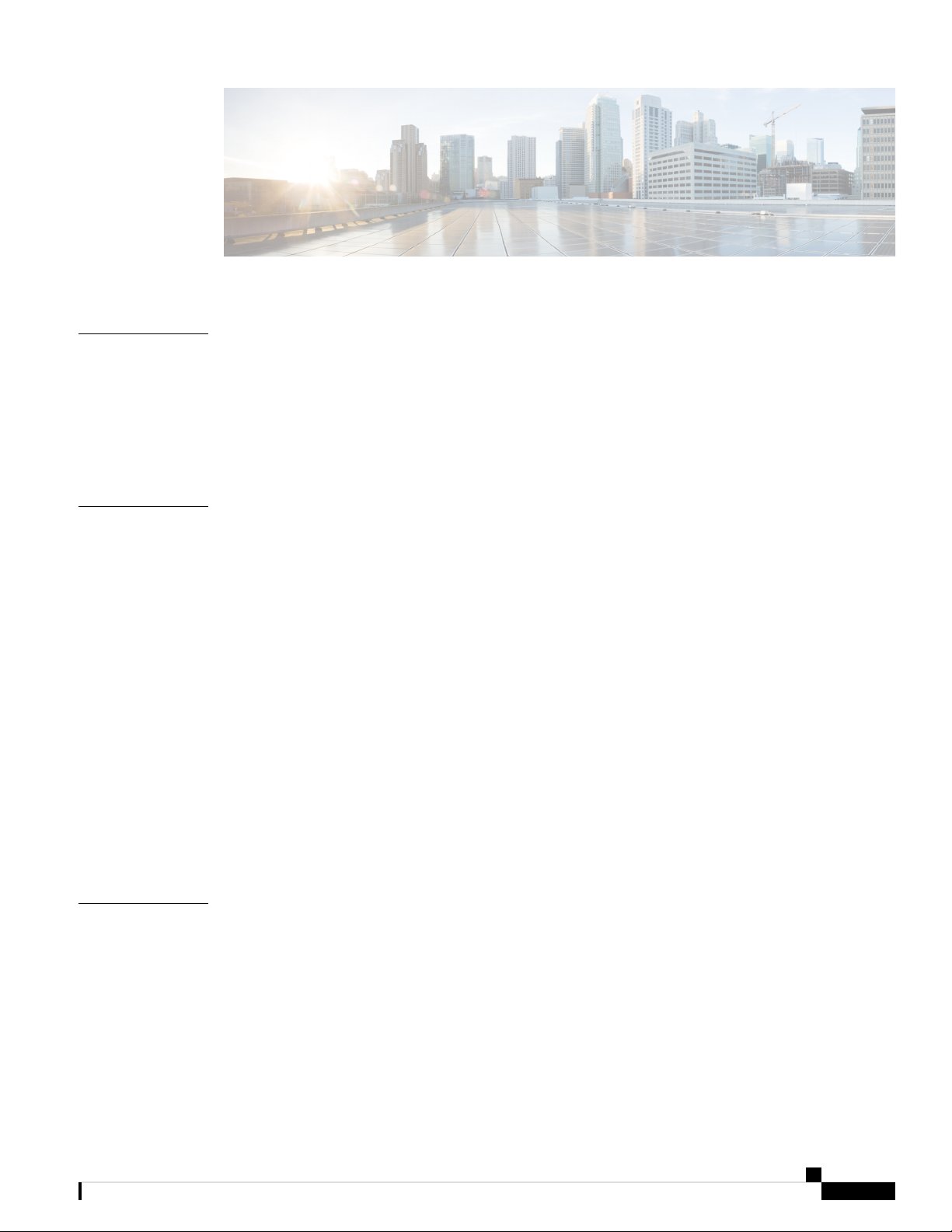
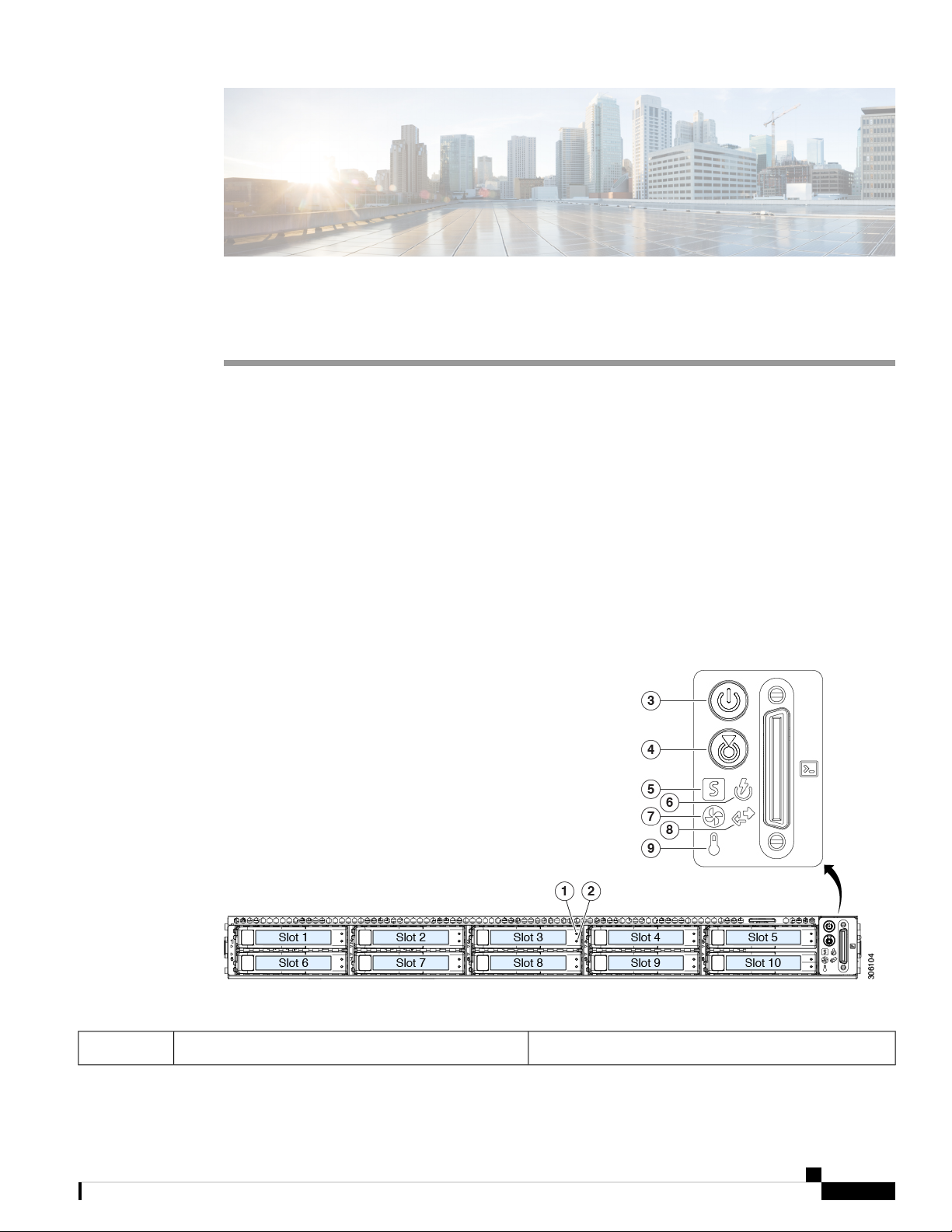
The following figure shows the front panel features of the small form-factor drive versions of the server.
For definitions of LED states, see Front-Panel LEDs, on page 21.
Cisco Application Services Engine Hardware Installation Guide
1
Page 8
External Features
Figure 1: Cisco SE-CL-L3 (SFF Drives) Front Panel
Overview
1
Fan status LED7Drive bays 1 – 10 support SAS/SATA hard disk
drives (HDDs) and solid state drives (SSDs)
2
Network link activity LED8• SE-CL-L3 : Drive bays 1 and 2 support
NVMe PCIe SSDs.
Temperature status LED9Power button/power status LED3
Pull-out asset tag10Unit identification button/LED4
11System status LED5
KVM connector
(used with KVM cable that provides one DB-15
VGA, one DB-9 serial, and two USB connectors)
-Power supply status LED6
SE-CL-L3 (LFF Drives) Front Panel Features
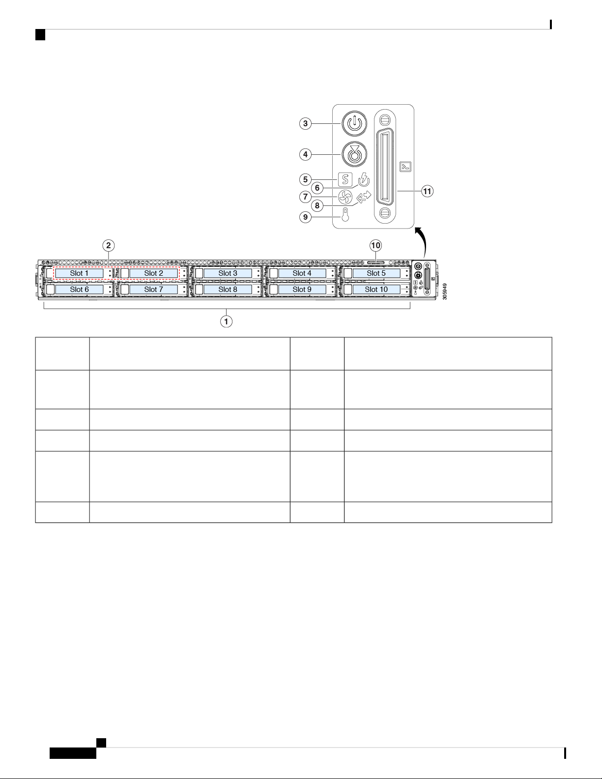
The following figure shows the front panel features of the large form-factor drive version of the server.
For definitions of LED states, see Front-Panel LEDs, on page 21.
Cisco Application Services Engine Hardware Installation Guide
2
Page 9
Overview
External Features
Figure 2: SE-CL-L3 (LFF Drives) Front Panel
1
Temperature status LED7Drive bays 1 – 4 support SAS/SATA HDDs and
SSDs
2
Power supply status LED8Drive bays 1 and 2 support NVMe PCIe SSDs.
A size-converter drive sled is required if 2.5-inch
SSDs are used.
Network link activity LED9Power button/power status LED3
10Unit identification button/LED4
KVM connector
(used with KVM cable that provides one DB-15
VGA, one DB-9 serial, and two USB connectors)
Pull-out asset tag11System health LED5
-Fan status LED6
SE-CL-L3 Rear Panel Features
The rear panel features are the same for all versions of the server.
For definitions of LED states, see Rear-Panel LEDs, on page 24.
Cisco Application Services Engine Hardware Installation Guide
3
Page 10

Serviceable Component Locations
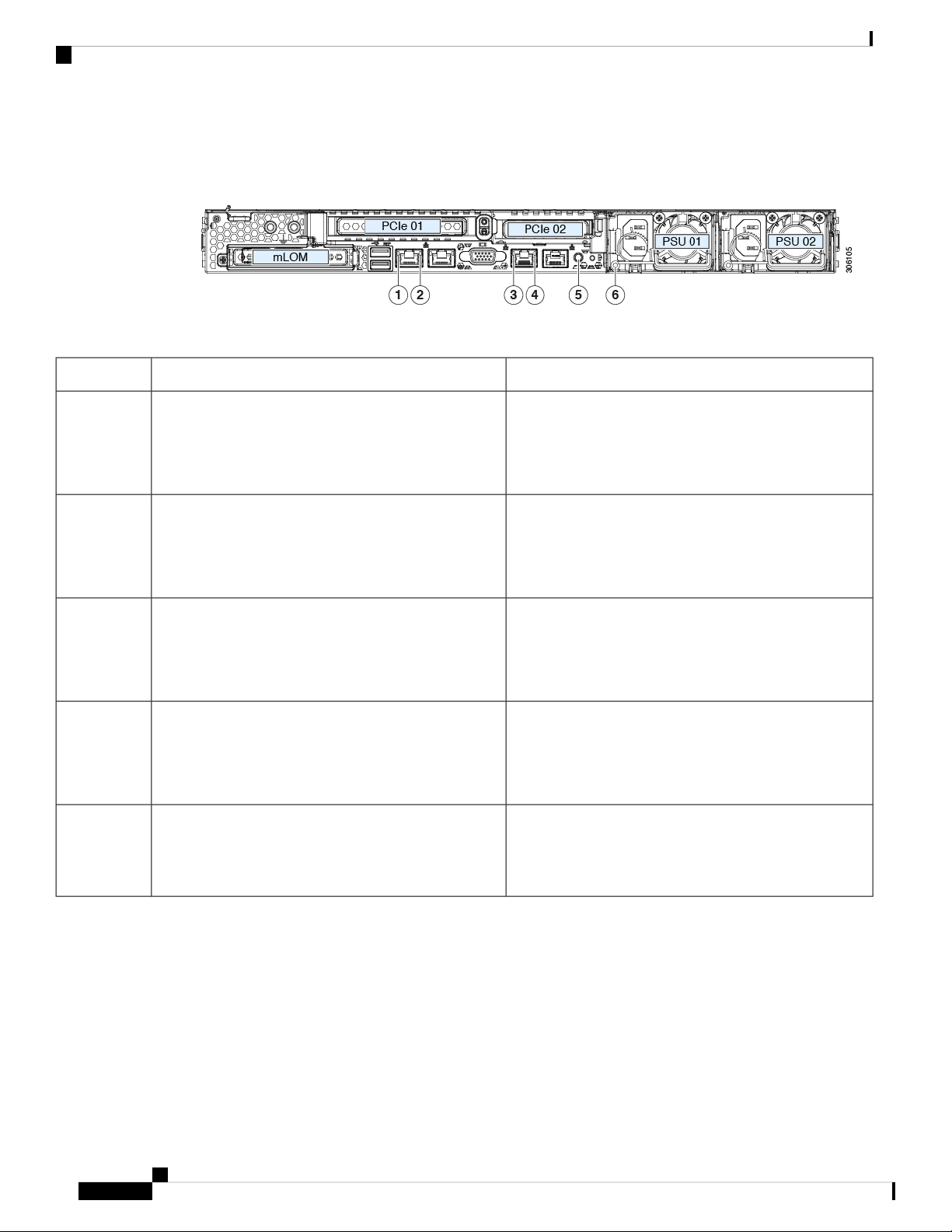
Figure 3: SE-CL-L3 Rear Panel
Overview
1
(x16 PCIe lane)
3
LAN2)
The dual LAN ports can support 1 Gbps and 10
Gbps, depending on the link partner capability.
9Dual 1-Gb/10-Gb Ethernet ports (LAN1 and
-Serial port (RJ-45 connector)6
Serviceable Component Locations
This topic shows the locations of the field-replaceable components and service-related items. The view in the
following figure shows the server with the top cover removed.
Rear unit identification button/LED7Modular LAN-on-motherboard (mLOM) card bay
Power supplies (two, redundant as 1+1)8USB 3.0 ports (two)2
PCIe riser 2/slot 2 (x16 lane)
Includes PCIe cable connectors for front-loading
NVMe SSDs (x8 lane)
PCIe riser 1/slot 1 (x16 lane)10VGA video port (DB-15 connector)4
Threaded holes for dual-hole grounding lug111-Gb Ethernet dedicated management port5
Cisco Application Services Engine Hardware Installation Guide
4
Page 11
Overview
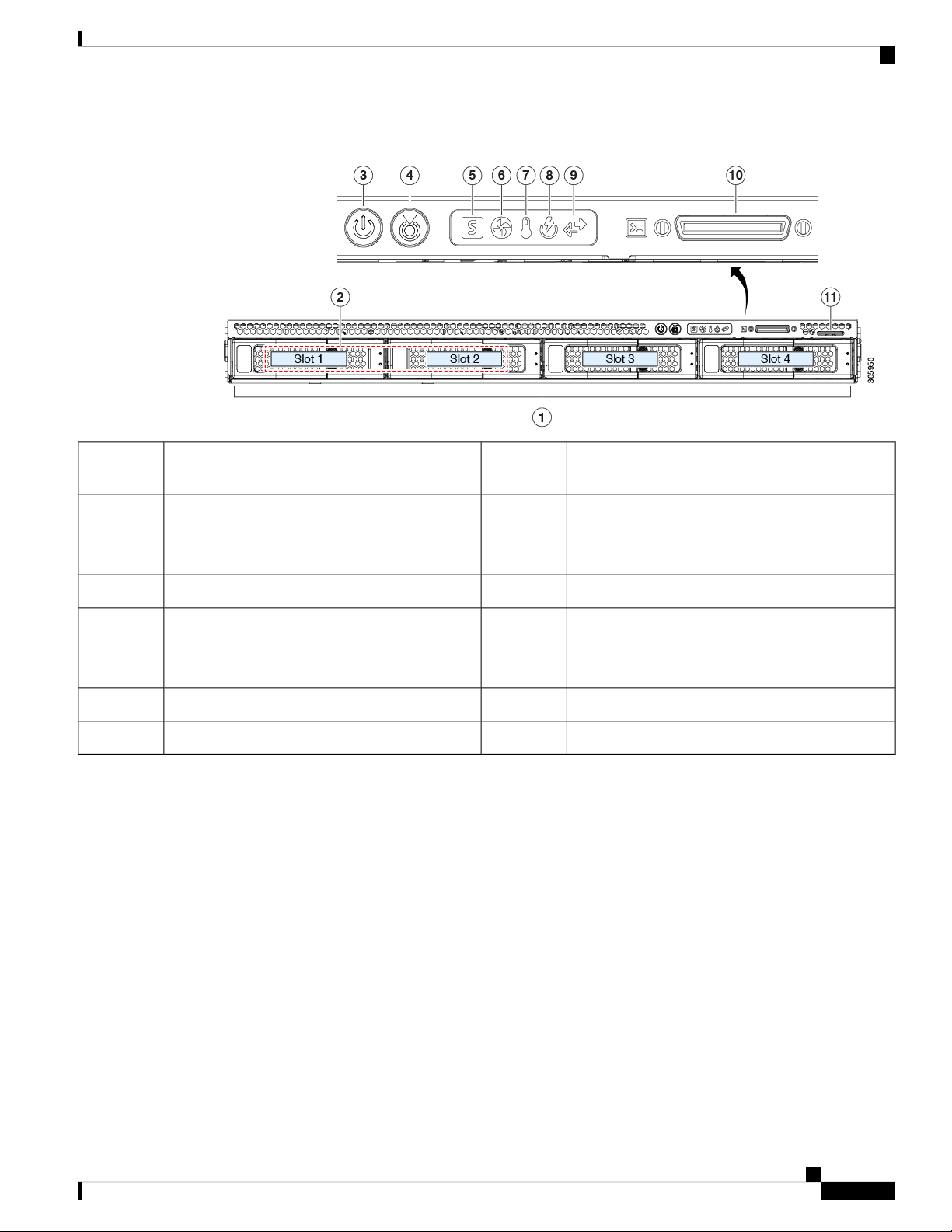
Figure 4: SE-CL-L3 , Serviceable Component Locations
Serviceable Component Locations
1
10Front-loading drive bays 1–10 support SAS/SATA
drives.
Power supplies (hot-swappable when redundant as
1+1)
• SE-CL-L3 : Drive bays 1 and 2 support
NVMe PCIe SSDs.
11Cooling fan modules (seven, hot-swappable)2
Trusted platform module (TPM) socket on
motherboard (not visible in this view)
12Supercap unit mounting bracket (RAID backup)3
PCIe riser 2/slot 2 (half-height, x16 lane)
Includes PCIe cable connectors for front-loading
NVMe SSDs (x8 lane)
13DIMM sockets on motherboard (12 per CPU)4
PCIe riser 1/slot 1 (full-height, x16 lane)
Includes socket for Micro-SD card
14CPUs and heatsinks (up to two)5
Modular LOM (mLOM) card bay on chassis floor
(x16 PCIe lane), not visible in this view
Cisco Application Services Engine Hardware Installation Guide
5
Page 12
Summary of Server Features
Overview
6
• SD card module with two SD card slots
• M.2 module with slots for either two SATA
M.2 drives or two NVMe M.2 drives
• Cisco Boot-Optimized M.2 RAID Controller
(module with two slots for SATA M.2 drives,
plus an integrated SATA RAID controller that
can control the two M.2 drives in a RAID 1
array)
Summary of Server Features
The following table lists a summary of server features.
15Mini-storage module socket. Options:
16Chassis intrusion switch (optional)7
-RTC battery, vertical socket9
Modular RAID (mRAID) riser, can optionally be a
riser that supports either:
• Hardware RAID controller card
• Interposer card for embedded SATA RAID
PCIe cable connectors for front-loading NVMe SSDs
on PCIe riser 2
Micro-SD card socket on PCIe riser 117Internal USB 3.0 port on motherboard8
Central Processor
Baseboard management
DescriptionFeature
One rack-unit (1RU) chassisChassis
Up to two CPUs from the Intel Xeon Processor Scalable Family.
This includes CPUs from the following series:
• Intel Xeon Silver 4XXX Processors
24 DDR4 DIMM sockets on the motherboard (12 each CPU)Memory
Multi-bit error protection is supportedMulti-bit error protection
BMC, running Cisco Integrated Management Controller (Cisco
IMC) firmware.
Depending on your Cisco IMC settings, Cisco IMC can be
accessed through the 1-Gb dedicated management port, the
1-Gb/10-Gb Ethernet LAN ports, or a Cisco virtual interface card.
Cisco Application Services Engine Hardware Installation Guide
6
Page 13
Overview
Summary of Server Features
DescriptionFeature
Network and management I/O
Modular LOM
Power
Rear panel:
• One 1-Gb Ethernet dedicated management port (RJ-45
connector)
• Two 1-Gb/10-Gb BASE-T Ethernet LAN ports (RJ-45
connectors)
The dual LAN ports can support 1 Gbps and 10 Gbps,
depending on the link partner capability.
• One RS-232 serial port (RJ-45 connector)
• One VGA video connector port (DB-15 connector)
• Two USB 3.0 ports
Front panel:
• One front-panel keyboard/video/mouse (KVM) connector
that is used with the KVM cable, which provides two USB
2.0, one VGA, and one DB-9 serial connector.
One dedicated socket (x16 PCIe lane) that can be used to add an
mLOM card for additional rear-panel connectivity.
One power supply:
ACPI
PCIe I/O
InfiniBand
Storage, front-panel
• AC power supplies 1050 W AC each
The advanced configuration and power interface (ACPI) 4.0
standard is supported.
Seven hot-swappable fan modules for front-to-rear cooling.Cooling
Two horizontal PCIe expansion slots on a PCIe riser assembly.
See PCIe Slot Specifications, on page 60 for specifications of the
slots.
The PCIe bus slots in this server support the InfiniBand
architecture.
The server is orderable in three different versions, each with a
different front panel/drive-backplane configuration.
• SE-CL-L3 , Small form-factor (SFF) drives, with 10-drive
backplane. Supports up to 10 2.5-inch SAS/SATA drives.
Drive bays 1 and 2 support NVMe SSDs.
Cisco Application Services Engine Hardware Installation Guide
7
Page 14
Summary of Server Features
Overview
DescriptionFeature
Storage, internal
Storage management
The server has these internal storage options:
• One USB port on the motherboard.
• One micro-SD card socket on PCIe riser 1.
• Mini-storage module socket, optionally with either:
• SD card module. Supports up to two SD cards.
• M.2 SSD module. Supports either two SATA M.2 SSDs
or two NVMe M.2 SSDs.
• Cisco Boot-Optimized M.2 RAID Controller (module
with two slots for SATA M.2 drives, plus an integrated
SATA RAID controller that can control the two SATA
M.2 drives in a RAID 1 array)
The server has a dedicated internal mRAID riser that supports
one of the following storage-controller options:
• A PCIe-style Cisco modular RAID controller card
(SAS/SATA).
• A PCIe-style interposer card for the server’s embedded
SATA RAID controller.
RAID backup
For a detailed list of storage controller options, see Supported
Storage Controllers and Cables, on page 91.
The server has a mounting bracket near the cooling fans for the
supercap unit that is used with the Cisco modular RAID controller
card.
Integrated VGA video.Integrated video
Cisco Application Services Engine Hardware Installation Guide
8
Page 15
Installing the Server
• Preparing for Installation, on page 9
• Installing the Server in a Rack, on page 12
• Installing the Cable Management Arm (Optional), on page 14
• Reversing the Cable Management Arm (Optional), on page 15
• Initial Server Setup, on page 16
• Connecting to the Server Locally For Setup, on page 17
• Connecting to the Server Remotely For Setup, on page 18
• Updating the BIOS and Cisco IMC Firmware, on page 19
• Accessing the System BIOS, on page 19
• Smart Access Serial, on page 20
Preparing for Installation
This section contains the following topics:
CHAPTER 2
Installation Warnings and Guidelines
Note
Before you install, operate, or service a server, review the Regulatory Compliance and Safety Information for
important safety information.
Warning
IMPORTANT SAFETY INSTRUCTIONS
This warning symbol means danger. You are in a situation that could cause bodily injury. Before you work
on any equipment, be aware of the hazards involved with electrical circuitry and be familiar with standard
practices for preventing accidents. Use the statement number provided at the end of each warning to locate
its translation in the translated safety warnings that accompanied this device.
Statement 1071
Cisco Application Services Engine Hardware Installation Guide
9
Page 16
Installation Warnings and Guidelines
Installing the Server
Warning
Warning
Warning
Warning
To prevent the system from overheating, do not operate it in an area that exceeds the maximum recommended
ambient temperature of: 35° C (95° F).
Statement 1047
The plug-socket combination must be accessible at all times, because it serves as the main disconnecting
device.
Statement 1019
This product relies on the building’s installation for short-circuit (overcurrent) protection. Ensure that the
protective device is rated not greater than: 250 V, 15 A.
Statement 1005
Installation of the equipment must comply with local and national electrical codes.
Statement 1074
Warning
Caution
Caution
This unit is intended for installation in restricted access areas. A restricted access area can be accessed only
through the use of a special tool, lock, and key, or other means of security.
Statement 1017
To ensure proper airflow it is necessary to rack the servers using rail kits. Physically placing the units on top
of one another or “stacking” without the use of the rail kits blocks the air vents on top of the servers, which
could result in overheating, higher fan speeds, and higher power consumption. We recommend that you mount
your servers on rail kits when you are installing them into the rack because these rails provide the minimal
spacing required between the servers. No additional spacing between the servers is required when you mount
the units using rail kits.
Avoid uninterruptible power supply (UPS) types that use ferroresonant technology. These UPS types can
become unstable with systems such as the Cisco UCS, which can have substantial current draw fluctuations
from fluctuating data traffic patterns.
When you are installing a server, use the following guidelines:
• Plan your site configuration and prepare the site before installing the server.
Cisco Application Services Engine Hardware Installation Guide
10
Page 17

Installing the Server
• Ensure that there is adequate space around the server to allow for accessing the server and for adequate
airflow. The airflow in this server is from front to back.
• Ensure that the air-conditioning meets the thermal requirements listed in the Environmental Specifications,
on page 85.
• Ensure that the cabinet or rack meets the requirements listed in the Rack Requirements, on page 11.
• Ensure that the site power meets the power requirements listed in the Power Specifications, on page 86.
If available, you can use an uninterruptible power supply (UPS) to protect against power failures.
Rack Requirements
The rack must be of the following type:
• A standard 19-in. (48.3-cm) wide, four-post EIA rack, with mounting posts that conform to English
universal hole spacing, per section 1 of ANSI/EIA-310-D-1992.
• The rack-post holes can be square 0.38-inch (9.6 mm), round 0.28-inch (7.1 mm), #12-24 UNC, or #10-32
UNC when you use the Cisco-supplied slide rails.
Rack Requirements
• The minimum vertical rack space per server must be one rack unit (RU), equal to 1.75 in. (44.45 mm).
Supported Cisco Slide Rail Kits
The server supports the following rail kit:
• Cisco part UCSC-RAILB-M4= (ball-bearing slide rail kit)
Rack Installation Tools Required
The slide rails sold by Cisco Systems for this server do not require tools for installation.
Slide Rail and Cable Management Arm Dimensions
The slide rails for this server have an adjustment range of 24 to 36 inches (610 to 914 mm).
The optional cable management arm (CMA) adds additional length requirements:
• The additional distance from the rear of the server to the rear of the CMA is 5.4 inches (137.4 mm).
• The total length of the server including the CMA is 35.2 inches (894 mm).
Cisco Application Services Engine Hardware Installation Guide
11
Page 18
Installing the Server in a Rack
Installing the Server in a Rack
Installing the Server
Warning
Step 1 Attach the inner rails to the sides of the server:
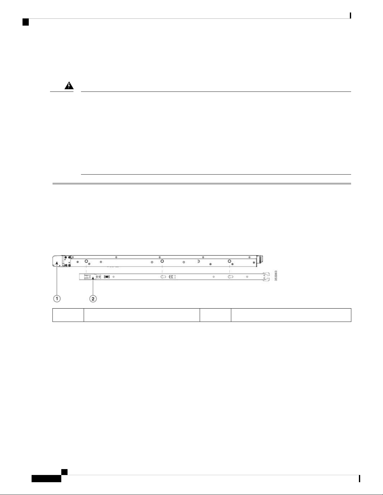
a) Align an inner rail with one side of the server so that the three keyed slots in the rail align with the three pegs on the
b) Set the keyed slots over the pegs, and then slide the rail toward the front to lock it in place on the pegs. The front slot
c) Install the second inner rail to the opposite side of the server.
Figure 5: Attaching the Inner Rail to the Side of the Server
To prevent bodily injury when mounting or servicing this unit in a rack, you must take special precautions to
ensure that the system remains stable. The following guidelines are provided to ensure your safety:
This unit should be mounted at the bottom of the rack if it is the only unit in the rack.
When mounting this unit in a partially filled rack, load the rack from the bottom to the top with the heaviest
component at the bottom of the rack.
If the rack is provided with stabilizing devices, install the stabilizers before mounting or servicing the unit in
the rack.
Statement 1006
side of the server.
has a metal clip that locks over the front peg.
Locking clip on front of inner rail2Front of server1
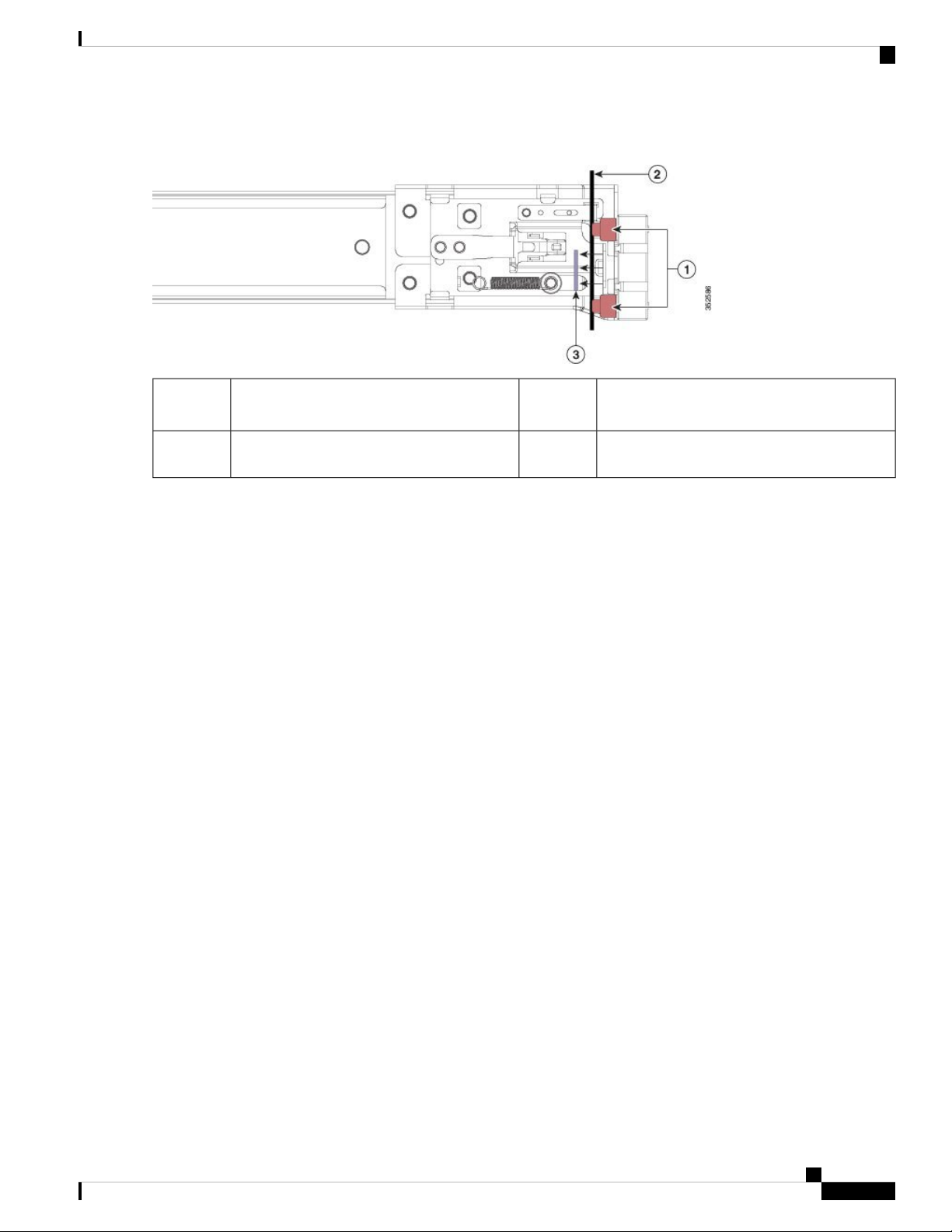
Step 2 Open the front securing plate on both slide-rail assemblies. The front end of the slide-rail assembly has a spring-loaded
securing plate that must be open before you can insert the mounting pegs into the rack-post holes.
On the outside of the assembly, push the green-arrow button toward the rear to open the securing plate.
Cisco Application Services Engine Hardware Installation Guide
12
Page 19
Installing the Server
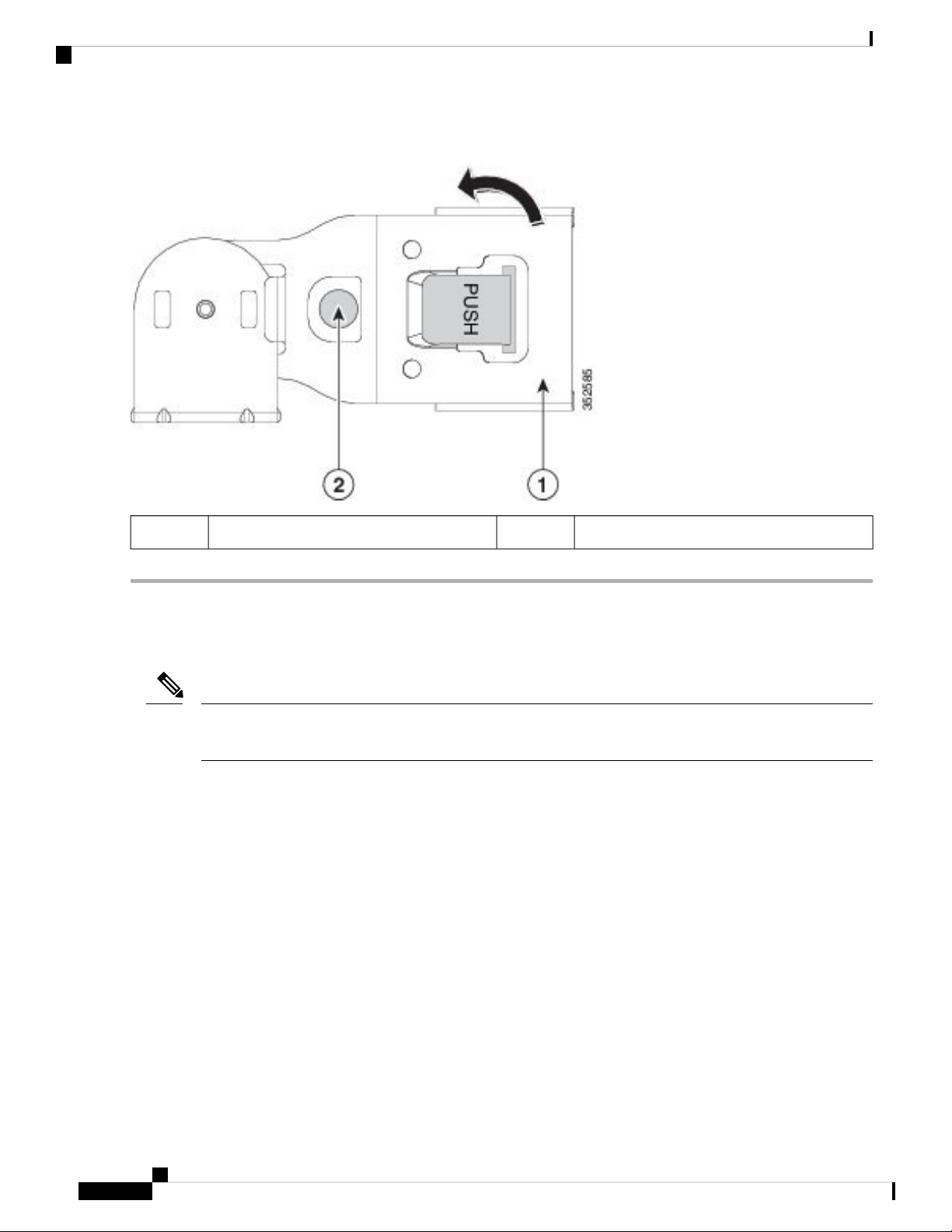
Figure 6: Front Securing Mechanism, Inside of Front End
Installing the Server in a Rack
2
securing plate
Step 3 Install the outer slide rails into the rack:
a) Align one slide-rail assembly front end with the front rack-post holes that you want to use.
The slide rail front-end wraps around the outside of the rack post and the mounting pegs enter the rack-post holes
from the outside-front.
Note
The rack post must be between the mounting pegs and the open securing plate.
b) Push the mounting pegs into the rack-post holes from the outside-front.
c) Press the securing plate release button, marked PUSH. The spring-loaded securing plate closes to lock the pegs in
place.
d) Adjust the slide-rail length, and then push the rear mounting pegs into the corresponding rear rack-post holes. The
slide rail must be level front-to-rear.
The rear mounting pegs enter the rear rack-post holes from the inside of the rack post.
e) Attach the second slide-rail assembly to the opposite side of the rack. Ensure that the two slide-rail assemblies are at
the same height and are level front-to-back.
f) Pull the inner slide rails on each assembly out toward the rack front until they hit the internal stops and lock in place.
Step 4 Insert the server into the slide rails:
3Front mounting pegs1
Securing plate shown pulled back to the open
position
-Rack post between mounting pegs and opened
Caution
This server can weigh up to 60 pounds (27 kilograms) when fully loaded with components. We recommend
that you use a minimum of two people or a mechanical lift when lifting the server. Attempting this procedure
alone could result in personal injury or equipment damage.
a) Align the rear ends of the inner rails that are attached to the server sides with the front ends of the empty slide rails
on the rack.
b) Push the inner rails into the slide rails on the rack until they stop at the internal stops.
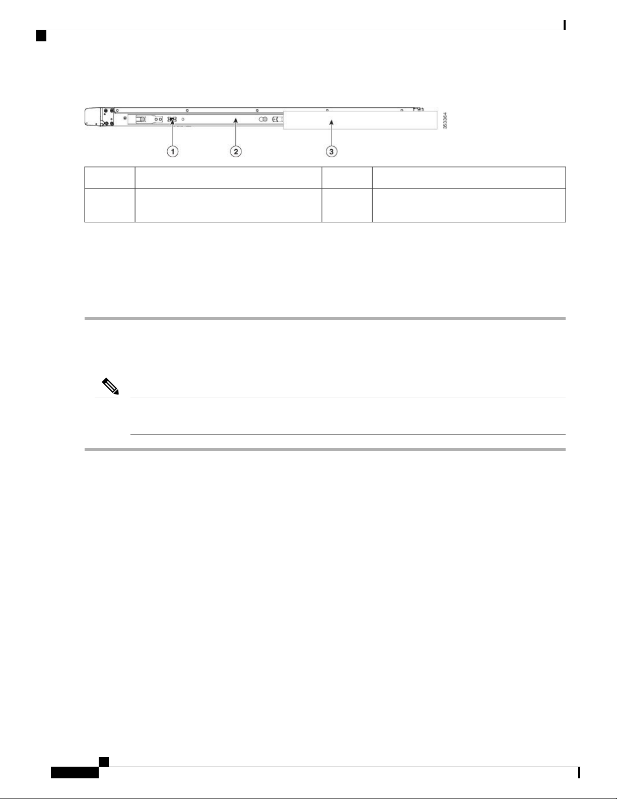
c) Slide the inner-rail release clip toward the rear on both inner rails, and then continue pushing the server into the rack
until its front slam-latches engage with the rack posts.
Cisco Application Services Engine Hardware Installation Guide
13
Page 20
Installing the Cable Management Arm (Optional)
Figure 7: Inner-Rail Release Clip
Installing the Server
Outer slide rail attached to rack post3Inner-rail release clip1
2
outer slide rail
Step 5 (Optional) Secure the server in the rack more permanently by using the two screws that are provided with the slide rails.
Perform this step if you plan to move the rack with servers installed.
With the server fully pushed into the slide rails, open a hinged slam latch lever on the front of the server and insert a
screw through the hole that is under the lever. The screw threads into the static part of the rail on the rack post and prevents
the server from being pulled out. Repeat for the opposite slam latch.
-Inner rail attached to server and inserted into
Installing the Cable Management Arm (Optional)
Note
The cable management arm (CMA) is reversible left-to-right. To reverse the CMA, see Reversing the Cable
Management Arm (Optional), on page 15 before installation.
Step 1 With the server pushed fully into the rack, slide the CMA tab of the CMA arm that is farthest from the server onto the
end of the stationary slide rail that is attached to the rack post. Slide the tab over the end of the rail until it clicks and
locks.
Cisco Application Services Engine Hardware Installation Guide
14
Page 21
Installing the Server
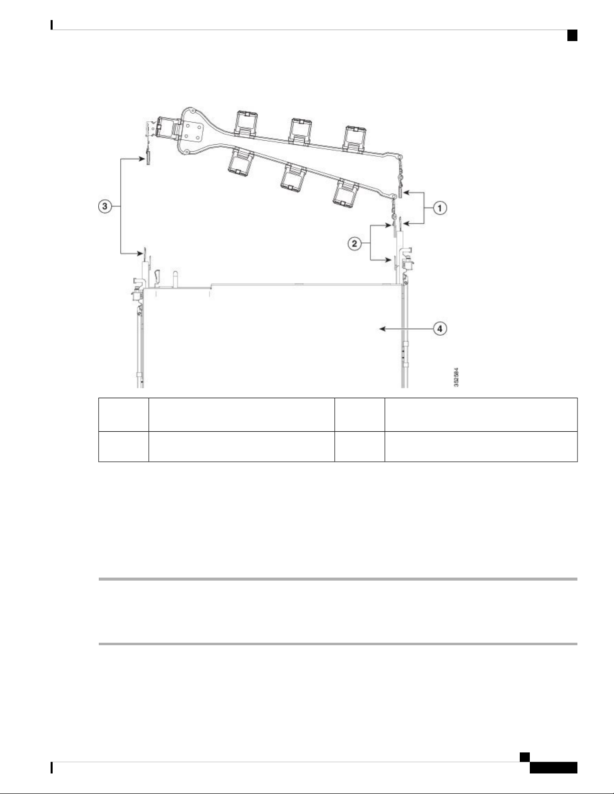
Figure 8: Attaching the CMA to the Rear Ends of the Slide Rails
Reversing the Cable Management Arm (Optional)
1
to end of stationary outer slide rail.
2
to end of inner slide rail attached to server.
Step 2 Slide the CMA tab that is closest to the server over the end of the inner rail that is attached to the server. Slide the tab
over the end of the rail until it clicks and locks
Step 3 Pull out the width-adjustment slider that is at the opposite end of the CMA assembly until it matches the width of your
rack.
Step 4 Slide the CMA tab that is at the end of the width-adjustment slider onto the end of the stationary slide rail that is attached
to the rack post. Slide the tab over the end of the rail until it clicks and locks.
Step 5 Open the hinged flap at the top of each plastic cable guide and route your cables through the cable guides as desired.
3CMA tab on arm farthest from server attaches
CMA tab on width-adjustment slider attaches
to end of stationary outer slide rail.
Rear of server4CMA tab on arm closest to the server attaches
Reversing the Cable Management Arm (Optional)
Step 1 Rotate the entire CMA assembly 180 degrees, left-to-right. The plastic cable guides must remain pointing upward.
Step 2 Flip the tabs at the ends of the CMA arms so that they point toward the rear of the server.
Step 3 Pivot the tab that is at the end of the width-adjustment slider. Depress and hold the metal button on the outside of the tab
and pivot the tab 180 degrees so that it points toward the rear of the server.
Cisco Application Services Engine Hardware Installation Guide
15
Page 22
Initial Server Setup
Figure 9: Reversing the CMA
Installing the Server
Initial Server Setup
Note
This section describes how to power on the server, assign an IP address, and connect to server management
when using the server in standalone mode.
Server Default Settings
The server is shipped with these default settings:
• The NIC mode is Shared LOM EXT.
Shared LOM EXT mode enables the 1-Gb/10-Gb Ethernet ports and the ports on any installed Cisco
virtual interface card (VIC) to access the Cisco Integrated Management Interface (Cisco IMC).
• The NIC redundancy is Active-Active. All Ethernet ports are utilized simultaneously.
• DHCP is enabled.
Metal button on outside of tab2CMA tab on end of width-adjustment slider1
• IPv4 is enabled.
Connection Methods
There are two methods for connecting to the system for initial setup:
Cisco Application Services Engine Hardware Installation Guide
16
Page 23
Installing the Server
Connecting to the Server Locally For Setup
• Local setup—Use this procedure if you want to connect a keyboard and monitor directly to the system
for setup. This procedure can use a KVM cable (Cisco PID N20-BKVM) or the ports on the rear of the
server.
• Remote setup—Use this procedure if you want to perform setup through your dedicated management
LAN.
Note
To configure the system remotely, you must have a DHCP server on the same
network as the system. Your DHCP server must be preconfigured with the range
of MAC addresses for this server node. The MAC address is printed on a label
that is on the pull-out asset tag on the front panel. This server node has a range
of six MAC addresses assigned to the Cisco IMC. The MAC address printed on
the label is the beginning of the range of six contiguous MAC addresses.
This section contains the following topics:
Connecting to the Server Locally For Setup
This procedure requires the following equipment:
• VGA monitor
• USB keyboard
• Either the supported Cisco KVM cable (Cisco PID N20-BKVM); or a USB cable and VGA DB-15 cable
Step 1 Attach a power cord to each power supply in your server, and then attach each power cord to a grounded power outlet.
Wait for approximately two minutes to let the server boot to standby power during the first bootup. You can verify system
power status by looking at the system Power Status LED on the front panel. The system is in standby power mode when
the LED is amber.
Step 2 Connect a USB keyboard and VGA monitor to the server using one of the following methods:
• Connect an optional KVM cable (Cisco PID N20-BKVM) to the KVM connector on the front panel. Connect your
USB keyboard and VGA monitor to the KVM cable.
• Connect a USB keyboard and VGA monitor to the corresponding connectors on the rear panel.
Step 3 Open the Cisco IMC Configuration Utility:
a) Press and hold the front panel power button for four seconds to boot the server.
b) During bootup, press F8 when prompted to open the Cisco IMC Configuration Utility.
Note
The following are the requirements for Strong Password:
The first time that you enter the Cisco IMC Configuration Utility, you are prompted to change the default
password. The default password is password. The Strong Password feature is enabled.
• The password can have minimum 8 characters; maximum 14 characters.
Cisco Application Services Engine Hardware Installation Guide
17
Page 24
Connecting to the Server Remotely For Setup
• The password must not contain the user’s name.
• The password must contain characters from three of the following four categories:
• English uppercase letters (A through Z)
• English lowercase letters (a through z)
• Base 10 digits (0 through 9)
• Non-alphabetic characters !, @, #, $, %, ^, &, *, -, _, =, “
Connecting to the Server Remotely For Setup
This procedure requires the following equipment:
• One RJ-45 Ethernet cable that is connected to your management LAN.
Installing the Server
Before you begin
Note
To configure the system remotely, you must have a DHCP server on the same network as the system. Your
DHCP server must be preconfigured with the range of MAC addresses for this server node. The MAC address
is printed on a label that is on the pull-out asset tag on the front panel. This server node has a range of six
MAC addresses assigned to the Cisco IMC. The MAC address printed on the label is the beginning of the
range of six contiguous MAC addresses.
Step 1 Attach a power cord to each power supply in your server, and then attach each power cord to a grounded power outlet.
Wait for approximately two minutes to let the server boot to standby power during the first bootup. You can verify system
power status by looking at the system Power Status LED on the front panel. The system is in standby power mode when
the LED is amber.
Step 2 Plug your management Ethernet cable into the dedicated management port on the rear panel.
Step 3 Allow your preconfigured DHCP server to assign an IP address to the server node.
Step 4 Use the assigned IP address to access and log in to the Cisco IMC for the server node. Consult with your DHCP server
administrator to determine the IP address.
Note
Step 5 From the Cisco IMC Server Summary page, click Launch KVM Console. A separate KVM console window opens.
Step 6 From the Cisco IMC Summary page, click Power Cycle Server. The system reboots.
Step 7 Select the KVM console window.
The default user name for the server is admin. The default password is password.
Note
Step 8 When prompted, press F8 to enter the Cisco IMC Configuration Utility. This utility opens in the KVM console window.
18
The KVM console window must be the active window for the following keyboard actions to work.
Cisco Application Services Engine Hardware Installation Guide
Page 25
Installing the Server
Updating the BIOS and Cisco IMC Firmware
Note
The following are the requirements for Strong Password:
The first time that you enter the Cisco IMC Configuration Utility, you are prompted to change the default
password. The default password is password. The Strong Password feature is enabled.
• The password can have minimum 8 characters; maximum 14 characters.
• The password must not contain the user’s name.
• The password must contain characters from three of the following four categories:
• English uppercase letters (A through Z)
• English lowercase letters (a through z)
• Base 10 digits (0 through 9)
• Non-alphabetic characters !, @, #, $, %, ^, &, *, -, _, =, “
Updating the BIOS and Cisco IMC Firmware
Caution
When you upgrade the BIOS firmware, you must also upgrade the Cisco IMC firmware to the same version
or the server does not boot. Do not power off the server until the BIOS and Cisco IMC firmware are matching
or the server does not boot.
Cisco provides the Cisco Host Upgrade Utility to assist with simultaneously upgrading the BIOS, Cisco IMC,
and other firmware to compatible levels.
Accessing the System BIOS
Step 1 Enter the BIOS Setup Utility by pressing the F2 key when prompted during bootup.
Note
Step 2 Use the arrow keys to select the BIOS menu page.
Step 3 Highlight the field to be modified by using the arrow keys.
Step 4 Press Enter to select the field that you want to change, and then modify the value in the field.
Step 5 Press the right arrow key until the Exit menu screen is displayed.
Step 6 Follow the instructions on the Exit menu screen to save your changes and exit the setup utility (or press F10). You can
exit without saving changes by pressing Esc.
The version and build of the current BIOS are displayed on the Main page of the utility.
Cisco Application Services Engine Hardware Installation Guide
19
Page 26
Smart Access Serial
Smart Access Serial
This server supports the Smart Access Serial feature. This feature allows you to switch between host serial
and Cisco IMC CLI.
• This feature has the following requirements:
• A serial cable connection, which can use either the RJ-45 serial connector on the server rear panel,
or a DB-9 connection when using the KVM cable (Cisco PID N20-BKVM) on the front-panel KVM
console connector.
• Console redirection must be enabled in the server BIOS.
• Terminal type must be set to VT100+ or VTUFT8.
• Serial-over-LAN (SOL) must be disabled (SOL is disabled by default).
• To switch from host serial to Cisco IMC CLI, press Esc+9.
You must enter your Cisco IMC credentials to authenticate the connection.
Installing the Server
• To switch from Cisco IMC CLI to host serial, press Esc+8.
Note
You cannot switch to Cisco IMC CLI if the serial-over-LAN (SOL) feature is
enabled.
• After a session is created, it is shown in the CLI or web GUI by the name serial.
Cisco Application Services Engine Hardware Installation Guide
20
Page 27
Maintaining the Server
• Status LEDs and Buttons, on page 21
• Preparing For Component Installation, on page 26
• Removing and Replacing Components, on page 30
• Service Headers and Jumpers, on page 78
Status LEDs and Buttons
This section contains information for interpreting front, rear, and internal LED states.
Front-Panel LEDs
Figure 10: Front Panel LEDs
CHAPTER 3
Table 1: Front Panel LEDs, Definition of States
StatesLED Name
Cisco Application Services Engine Hardware Installation Guide
21
Page 28

Front-Panel LEDs
Maintaining the Server
1
SAS
SAS
1
NVMe
SAS/SATA drive fault
Note
NVMe solid state drive (SSD) drive tray
LEDs have different behavior than
SAS/SATA drive trays.
SAS/SATA drive activity LED2
NVMe SSD drive fault
Note
NVMe solid state drive (SSD) drive tray
LEDs have different behavior than
SAS/SATA drive trays.
• Off—The hard drive is operating properly.
• Amber—Drive fault detected.
• Amber, blinking—The device is rebuilding.
• Amber, blinking with one-second interval—Drive
locate function activated in the software.
• Off—There is no hard drive in the hard drive tray (no
access, no fault).
• Green—The hard drive is ready.
• Green, blinking—The hard drive is reading or writing
data.
• Off—The drive is not in use and can be safely
removed.
• Green—The drive is in use and functioning properly.
• Green, blinking—the driver is initializing following
insertion or the driver is unloading following an eject
command.
• Amber—The drive has failed.
NVMe
• Amber, blinking—A drive Locate command has been
issued in the software.
NVMe SSD activity2
• Off—No drive activity.
• Green, blinking—There is drive activity.
Power button/LED3
• Off—There is no AC power to the server.
• Amber—The server is in standby power mode. Power
is supplied only to the Cisco IMC and some
motherboard functions.
• Green—The server is in main power mode. Power is
supplied to all server components.
Unit identification4
• Off—The unit identification function is not in use.
• Blue, blinking—The unit identification function is
activated.
Cisco Application Services Engine Hardware Installation Guide
22
Page 29
Maintaining the Server
Front-Panel LEDs
System health5
• Green—The server is running in normal operating
condition.
• Green, blinking—The server is performing system
initialization and memory check.
• Amber, steady—The server is in a degraded
operational state (minor fault). For example:
• Power supply redundancy is lost.
• CPUs are mismatched.
• At least one CPU is faulty.
• At least one DIMM is faulty.
• At least one drive in a RAID configuration failed.
• Amber, 2 blinks—There is a major fault with the
system board.
• Amber, 3 blinks—There is a major fault with the
memory DIMMs.
• Amber, 4 blinks—There is a major fault with the
CPUs.
Power supply status6
• Green—All power supplies are operating normally.
• Amber, steady—One or more power supplies are in
a degraded operational state.
• Amber, blinking—One or more power supplies are
in a critical fault state.
Fan status7
• Green—All fan modules are operating properly.
• Amber, blinking—One or more fan modules breached
the non-recoverable threshold.
Network link activity8
• Off—The Ethernet LOM port link is idle.
• Green—One or more Ethernet LOM ports are
link-active, but there is no activity.
• Green, blinking—One or more Ethernet LOM ports
are link-active, with activity.
Temperature status9
• Green—The server is operating at normal temperature.
• Amber, steady—One or more temperature sensors
breached the critical threshold.
• Amber, blinking—One or more temperature sensors
breached the non-recoverable threshold.
Cisco Application Services Engine Hardware Installation Guide
23
Page 30
Rear-Panel LEDs
Rear-Panel LEDs
Figure 11: Rear Panel LEDs
Table 2: Rear Panel LEDs, Definition of States
Maintaining the Server
StatesLED Name
1
1-Gb/10-Gb Ethernet link speed (on both LAN1 and
LAN2)
• Amber—Link speed is 100 Mbps.
• Amber—Link speed is 1 Gbps.
• Green—Link speed is 10 Gbps.
2
1-Gb/10-Gb Ethernet link status (on both LAN1 and
LAN2)
• Off—No link is present.
• Green—Link is active.
• Green, blinking—Traffic is present on the active link.
1-Gb Ethernet dedicated management link speed3
• Off—Link speed is 10 Mbps.
• Amber—Link speed is 100 Mbps.
• Green—Link speed is 1 Gbps.
1-Gb Ethernet dedicated management link status4
• Off—No link is present.
• Green—Link is active.
• Green, blinking—Traffic is present on the active link.
Rear unit identification5
• Off—The unit identification function is not in use.
• Blue, blinking—The unit identification function is
activated.
Cisco Application Services Engine Hardware Installation Guide
24
Page 31

Maintaining the Server
Internal Diagnostic LEDs
Power supply status (one LED each power supply unit)6
AC power supplies:
• Off—No AC input (12 V main power off, 12 V
standby power off).
• Green, blinking—12 V main power off; 12 V standby
power on.
• Green, solid—12 V main power on; 12 V standby
power on.
• Amber, blinking—Warning threshold detected but 12
V main power on.
• Amber, solid—Critical error detected; 12 V main
power off (for example, over-current, over-voltage,
or over-temperature failure).
DC power supplies:
• Off—No DC input (12 V main power off, 12 V
standby power off).
• Green, blinking—12 V main power off; 12 V standby
power on.
• Green, solid—12 V main power on; 12 V standby
power on.
Internal Diagnostic LEDs
The server has internal fault LEDs for CPUs, DIMMs, and fan modules.
• Amber, blinking—Warning threshold detected but 12
V main power on.
• Amber, solid—Critical error detected; 12 V main
power off (for example, over-current, over-voltage,
or over-temperature failure).
Cisco Application Services Engine Hardware Installation Guide
25
Page 32

Preparing For Component Installation
Figure 12: Internal Diagnostic LED Locations
Maintaining the Server
1
connector on the motherboard)
• Amber—Fan has a fault or is not fully seated.
• Green—Fan is OK.
2
the motherboard).
These LEDs operate only when the server is in
standby power mode.
• Amber—CPU has a fault.
• Off—CPU is OK.
3Fan module fault LEDs (one behind each fan
-CPU fault LEDs (one behind each CPU socket on
Preparing For Component Installation
This section includes information and tasks that help prepare the server for component installation.
DIMM fault LEDs (one behind each DIMM socket
on the motherboard)
These LEDs operate only when the server is in
standby power mode.
• Amber—DIMM has a fault.
• Off—DIMM is OK.
Required Equipment For Service Procedures
The following tools and equipment are used to perform the procedures in this chapter:
Cisco Application Services Engine Hardware Installation Guide
26
Page 33

Maintaining the Server
Shutting Down and Removing Power From the Server
• T-30 Torx driver (supplied with replacement CPUs for heatsink removal)
• #1 flat-head screwdriver (supplied with replacement CPUs for heatsink removal)
• #1 Phillips-head screwdriver (for M.2 SSD and intrusion switch replacement)
• Electrostatic discharge (ESD) strap or other grounding equipment such as a grounded mat
Shutting Down and Removing Power From the Server
The server can run in either of two power modes:
• Main power mode—Power is supplied to all server components and any operating system on your drives
can run.
• Standby power mode—Power is supplied only to the service processor and certain components. It is safe
for the operating system and data to remove power cords from the server in this mode.
Caution
After a server is shut down to standby power, electric current is still present in the server. To completely
remove power as directed in some service procedures, you must disconnect all power cords from all power
supplies in the server.
You can shut down the server by using the front-panel power button or the software management interfaces.
Shutting Down Using the Power Button
Step 1 Check the color of the Power button/LED:
• Amber—The server is already in standby mode and you can safely remove power.
• Green—The server is in main power mode and must be shut down before you can safely remove power.
Step 2 Invoke either a graceful shutdown or a hard shutdown:
Caution
To avoid data loss or damage to your operating system, you should always invoke a graceful shutdown of the
operating system.
• Graceful shutdown—Press and release the Power button. The operating system performs a graceful shutdown and
the server goes to standby mode, which is indicated by an amber Power button/LED.
• Emergency shutdown—Press and hold the Power button for 4 seconds to force the main power off and immediately
enter standby mode.
Step 3 If a service procedure instructs you to completely remove power from the server, disconnect all power cords from the
power supplies in the server.
Shutting Down Using The Cisco IMC GUI
You must log in with user or admin privileges to perform this task.
Cisco Application Services Engine Hardware Installation Guide
27
Page 34

Maintaining the Server
Shutting Down Using The Cisco IMC CLI
Step 1 In the Navigation pane, click the Server tab.
Step 2 On the Server tab, click Summary.
Step 3 In the Actions area, click Power Off Server.
Step 4 Click OK.
The operating system performs a graceful shutdown and the server goes to standby mode, which is indicated by an amber
Power button/LED.
Step 5 If a service procedure instructs you to completely remove power from the server, disconnect all power cords from the
power supplies in the server.
Shutting Down Using The Cisco IMC CLI
You must log in with user or admin privileges to perform this task.
Step 1 At the server prompt, enter:
Example:
server# scope chassis
Step 2 At the chassis prompt, enter:
Example:
server/chassis# power shutdown
The operating system performs a graceful shutdown and the server goes to standby mode, which is indicated by an amber
Power button/LED.
Step 3 If a service procedure instructs you to completely remove power from the server, disconnect all power cords from the
power supplies in the server.
Removing the Server Top Cover
Step 1 Remove the top cover:
a) If the cover latch is locked, use a screwdriver to turn the lock 90-degrees counterclockwise to unlock it.
b) Lift on the end of the latch that has the green finger grip. The cover is pushed back to the open position as you lift
the latch.
c) Lift the top cover straight up from the server and set it aside.
Step 2 Replace the top cover:
a) With the latch in the fully open position, place the cover on top of the server about one-half inch (1.27 cm) behind
the lip of the front cover panel. The opening in the latch should fit over the peg that sticks up from the fan tray.
b) Press the cover latch down to the closed position. The cover is pushed forward to the closed position as you push
down the latch.
c) If desired, lock the latch by using a screwdriver to turn the lock 90-degrees clockwise.
Cisco Application Services Engine Hardware Installation Guide
28
Page 35

Maintaining the Server
Figure 13: Removing the Top Cover
Serial Number Location
Serial Number Location
The serial number for the server is printed on a label on the top of the server, near the front. See Removing
the Server Top Cover, on page 28.
Hot Swap vs Hot Plug
Some components can be removed and replaced without shutting down and removing power from the server.
This type of replacement has two varieties: hot-swap and hot-plug.
• Hot-swap replacement—You do not have to shut down the component in the software or operating
system. This applies to the following components:
Locking cover latch2Top cover1
Serial number label location3
Cisco Application Services Engine Hardware Installation Guide
29
Page 36

Removing and Replacing Components
• SAS/SATA hard drives
• SAS/SATA solid state drives
• Cooling fan modules
• Power supplies (when redundant as 1+1)
• Hot-plug replacement—You must take the component offline before removing it for the following
component:
• NVMe PCIe solid state drives
Removing and Replacing Components
Maintaining the Server
Warning
Caution
Blank faceplates and cover panels serve three important functions: they prevent exposure to hazardous voltages
and currents inside the chassis; they contain electromagnetic interference (EMI) that might disrupt other
equipment; and they direct the flow of cooling air through the chassis. Do not operate the system unless all
cards, faceplates, front covers, and rear covers are in place.
Statement 1029
When handling server components, handle them only by carrier edges and use an electrostatic discharge (ESD)
wrist-strap or other grounding device to avoid damage.
Tip
You can press the unit identification button on the front panel or rear panel to turn on a flashing, blue unit
identification LED on both the front and rear panels of the server. This button allows you to locate the specific
server that you are servicing when you go to the opposite side of the rack. You can also activate these LEDs
remotely by using the Cisco IMC interface.
This section describes how to install and replace server components.
Serviceable Component Locations
This topic shows the locations of the field-replaceable components and service-related items. The view in the
following figure shows the server with the top cover removed.
Cisco Application Services Engine Hardware Installation Guide
30
Page 37

Maintaining the Server
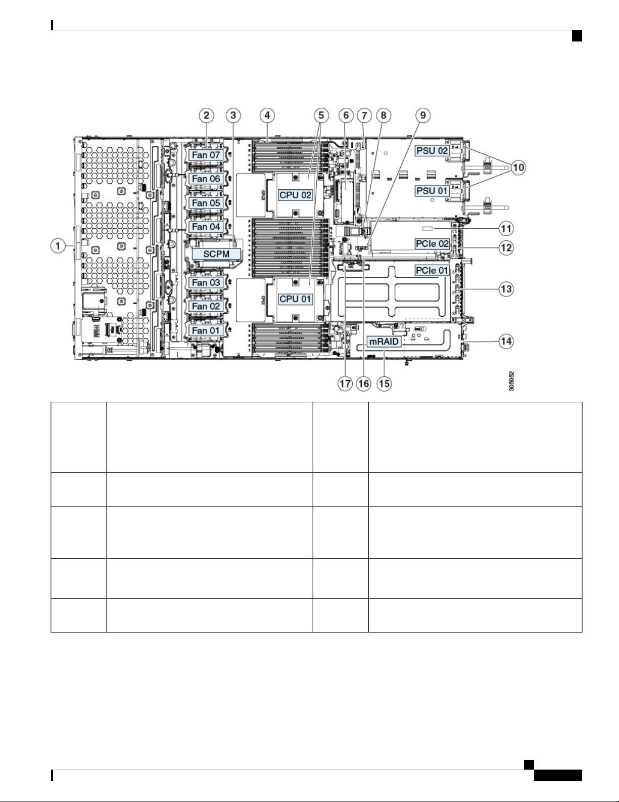
Figure 14: SE-CL-L3 , Serviceable Component Locations
Serviceable Component Locations
1
10Front-loading drive bays 1–10 support SAS/SATA
drives.
Power supplies (hot-swappable when redundant as
1+1)
• SE-CL-L3 : Drive bays 1 and 2 support
NVMe PCIe SSDs.
11Cooling fan modules (seven, hot-swappable)2
Trusted platform module (TPM) socket on
motherboard (not visible in this view)
12Supercap unit mounting bracket (RAID backup)3
PCIe riser 2/slot 2 (half-height, x16 lane)
Includes PCIe cable connectors for front-loading
NVMe SSDs (x8 lane)
13DIMM sockets on motherboard (12 per CPU)4
PCIe riser 1/slot 1 (full-height, x16 lane)
Includes socket for Micro-SD card
14CPUs and heatsinks (up to two)5
Modular LOM (mLOM) card bay on chassis floor
(x16 PCIe lane), not visible in this view
Cisco Application Services Engine Hardware Installation Guide
31
Page 38

Replacing SAS/SATA Hard Drives or Solid State Drives
Maintaining the Server
6
15Mini-storage module socket. Options:
• SD card module with two SD card slots
• M.2 module with slots for either two SATA
M.2 drives or two NVMe M.2 drives
Modular RAID (mRAID) riser, can optionally be a
riser that supports either:
• Hardware RAID controller card
• Interposer card for embedded SATA RAID
• Cisco Boot-Optimized M.2 RAID Controller
(module with two slots for SATA M.2 drives,
plus an integrated SATA RAID controller that
can control the two M.2 drives in a RAID 1
array)
16Chassis intrusion switch (optional)7
PCIe cable connectors for front-loading NVMe SSDs
on PCIe riser 2
Micro-SD card socket on PCIe riser 117Internal USB 3.0 port on motherboard8
-RTC battery, vertical socket9
Replacing SAS/SATA Hard Drives or Solid State Drives
Note
You do not have to shut down the server or drive to replace SAS/SATA hard drives or SSDs because they
are hot-swappable. To replace an NVMe PCIe SSD drive, which must be shut down before removal, see
Replacing a Front-Loading NVMe SSD, on page 36.
SAS/SATA Drive Population Guidelines
The server is orderable in the following different version
• SE-CL-L3 —Small form-factor (SFF) drives, with 10-drive backplane. Supports up to 10 2.5-inch
SAS/SATA drives. Drive bays 1 and 2 support NVMe SSDs.
Drive bay numbering is shown in the following figures.
Figure 15: Small Form-Factor Drive Versions, Drive Bay Numbering
Figure 16: Large Form-Factor Drive Version, Drive Bay Numbering
Observe these drive population guidelines for optimum performance:
• When populating drives, add drives to the lowest-numbered bays first.
Cisco Application Services Engine Hardware Installation Guide
32
Page 39

Maintaining the Server
• Keep an empty drive blanking tray in any unused bays to ensure proper airflow.
• You can mix SAS/SATA hard drives and SAS/SATA SSDs in the same server. However, you cannot
configure a logical volume (virtual drive) that contains a mix of hard drives and SSDs. That is, when
you create a logical volume, it must contain all SAS/SATA hard drives or all SAS/SATA SSDs.
4K Sector Format SAS/SATA Drives Considerations
About this task
• You must boot 4K sector format drives in UEFI mode, not legacy mode. UEFI mode is the system default.
Only if the mode has been changed and must be changed back to UEFI mode, see the following procedure.
• Do not configure 4K sector format and 512-byte sector format drives as part of the same RAID volume.
• Operating system support on 4K sector drives is as follows: Windows: Win2012 and Win2012R2; Linux:
RHEL 6.5, 6.6, 6.7, 7.0, 7.2; SLES 11 SP3, and SLES 12. ESXi/Vmware is not supported.
Setting Up UEFI Mode Booting in the BIOS Setup Utility
4K Sector Format SAS/SATA Drives Considerations
UEFI mode is the system default. Use this procedure if the mode has been changed and must be set back to
UEFI mode.
Step 1 Enter the BIOS setup utility by pressing the F2 key when prompted during bootup.
Step 2 Go to the Boot Options tab.
Step 3 Set Boot Mode to UEFI Mode.
Step 4 Under Boot Option Priorities, set your OS installation media (such as a virtual DVD) as your Boot Option #1.
Step 5 Press F10 to save changes and exit the BIOS setup utility. Allow the server to reboot.
Step 6 After the OS installs, verify the installation:
a) Enter the BIOS setup utility by pressing the F2 key when prompted during bootup.
b) Go to the Boot Options tab.
c) Under Boot Option Priorities, verify that the OS you installed is listed as your Boot Option #1.
Replacing a SAS/SATA Drive
Step 1 Remove the drive that you are replacing or remove a blank drive tray from the bay:
a) Press the release button on the face of the drive tray.
b) Grasp and open the ejector lever and then pull the drive tray out of the slot.
c) If you are replacing an existing drive, remove the four drive-tray screws that secure the drive to the tray and then lift
the drive out of the tray.
Step 2 Install a new drive:
a) Place a new drive in the empty drive tray and install the four drive-tray screws.
b) With the ejector lever on the drive tray open, insert the drive tray into the empty drive bay.
c) Push the tray into the slot until it touches the backplane, and then close the ejector lever to lock the drive in place.
Cisco Application Services Engine Hardware Installation Guide
33
Page 40

Replacing a Front-Loading NVMe SSD
Figure 17: Replacing a Drive in a Drive Tray
Maintaining the Server
Replacing a Front-Loading NVMe SSD
This section is for replacing 2.5-inch or 3.5-inch form-factor NVMe solid-state drives (SSDs) in front-panel
drive bays.
Front-Loading NVMe SSD Population Guidelines
The front drive bay support for 2.5-inch NVMe SSDs:
• SE-CL-L3 —Small form-factor (SFF) drives, with 10-drive backplane. Drive bays 1 and 2 support
2.5-inch NVMe SSDs.
Cisco Application Services Engine Hardware Installation Guide
34
Drive tray screws (two on each side)3Ejector lever1
Drive removed from drive tray4Release button2
Page 41

Maintaining the Server
Front-Loading NVME SSD Requirements and Restrictions
Observe these requirements:
• The server must have two CPUs. PCIe riser 2 is not available in a single-CPU system. PCIe riser 2 has
connectors for the cable that connects to the front-panel drive backplane.
• PCIe cable CBL-NVME-C220FF. This is the cable that carries the PCIe signal from the front-panel drive
backplane to PCIe riser 2. This cable is for all versions of this server.
• Hot-plug support must be enabled in the system BIOS. If you ordered the system with NVMe drives,
hot-plug support is enabled at the factory.
Observe these restrictions:
• NVMe SFF 2.5- and 3.5-inch SSDs support booting only in UEFI mode. Legacy boot is not supported.
For instructions on setting up UEFI boot, see 4K Sector Format SAS/SATA Drives Considerations, on
page 33.
• You cannot control NVMe PCIe SSDs with a SAS RAID controller because NVMe SSDs interface with
the server via the PCIe bus.
Front-Loading NVME SSD Requirements and Restrictions
• UEFI boot is supported in all supported operating systems. Hot-insertion and hot-removal are supported
in all supported operating systems except VMWare ESXi.
Enabling Hot-Plug Support in the System BIOS
Hot-plug (OS-informed hot-insertion and hot-removal) is disabled in the system BIOS by default.
• If the system was ordered with NVMe PCIe SSDs, the setting was enabled at the factory. No action is
required.
• If you are adding NVMe PCIe SSDs after-factory, you must enable hot-plug support in the BIOS. See
the following procedures.
Enabling Hot-Plug Support Using the BIOS Setup Utility
Step 1 Enter the BIOS setup utility by pressing the F2 key when prompted during bootup.
Step 2 Navigate to Advanced > PCI Subsystem Settings > NVMe SSD Hot-Plug Support.
Step 3 Set the value to Enabled.
Step 4 Save your changes and exit the utility.
Enabling Hot-Plug Support Using the Cisco IMC GUI
Step 1 Use a browser to log in to the Cisco IMC GUI for the server.
Step 2 Navigate to Compute > BIOS > Advanced > PCI Configuration.
Step 3 Set NVME SSD Hot-Plug Support to Enabled.
Step 4 Save your changes.
Cisco Application Services Engine Hardware Installation Guide
35
Page 42

Replacing a Front-Loading NVMe SSD
Replacing a Front-Loading NVMe SSD
This topic describes how to replace 2.5- or 3.5-inch form-factor NVMe SSDs in the front-panel drive bays.
Note
OS-surprise removal is not supported. OS-informed hot-insertion and hot-removal are supported on all
supported operating systems except VMware ESXi.
Note
OS-informed hot-insertion and hot-removal must be enabled in the system BIOS. See Enabling Hot-Plug
Support in the System BIOS, on page 35
Step 1 Remove an existing front-loading NVMe SSD:
a) Shut down the NVMe SSD to initiate an OS-informed removal. Use your operating system interface to shut down
the drive, and then observe the drive-tray LED:
Maintaining the Server
• Green—The drive is in use and functioning properly. Do not remove.
• Green, blinking—the driver is unloading following a shutdown command. Do not remove.
• Off—The drive is not in use and can be safely removed.
b) Press the release button on the face of the drive tray.
c) Grasp and open the ejector lever and then pull the drive tray out of the slot.
d) Remove the four drive tray screws that secure the SSD to the tray and then lift the SSD out of the tray.
Note
If this is the first time that front-loading NVMe SSDs are being installed in the server, you must install PCIe
cable CBL-NVME-C220FF before installing the drive. See Installing a PCIe Cable For Front-Loading NVMe
SSDs, on page 37.
Step 2 Install a new front-loading NVMe SSD:
a) Place a new SSD in the empty drive tray and install the four drive-tray screws.
b) With the ejector lever on the drive tray open, insert the drive tray into the empty drive bay.
c) Push the tray into the slot until it touches the backplane, and then close the ejector lever to lock the drive in place.
Step 3 Observe the drive-tray LED and wait until it returns to solid green before accessing the drive:
• Off—The drive is not in use.
• Green, blinking—the driver is initializing following hot-plug insertion.
• Green—The drive is in use and functioning properly.
Cisco Application Services Engine Hardware Installation Guide
36
Page 43

Maintaining the Server
Figure 18: Replacing a Drive in a Drive Tray
Installing a PCIe Cable For Front-Loading NVMe SSDs
Installing a PCIe Cable For Front-Loading NVMe SSDs
The front-loading NVMe SSDs interface with the server via the PCIe bus. Cable CBL-NVME-C220FF
connects the front-panel drive backplane to the PCIe riser 2 board on the PCIe riser assembly.
• If the server was ordered with 2.5- or 3.5-inch form-factor NVMe SSDs, this cable was preinstalled at
the factory. No action is required.
• If you are adding 2.5- or 3.5-inch form-factor NVMe SSDs for the first time, you must order and install
the cable as described in the following procedure.
Cisco Application Services Engine Hardware Installation Guide
Drive tray screws (two on each side)3Ejector lever1
Drive removed from drive tray4Release button2
37
Page 44

Maintaining the Server
Replacing Fan Modules
Step 1 Connect the two connectors on one end of the cable to the PCIE-A1 and PCIE-A2 connectors on the drive backplane.
Step 2 Route the cables through the chassis cable guides to the rear of the server as shown below.
Step 3 Connect the single connector on the other end of the cable to the PCIE-FRONT connector on PCIe riser 2.
Figure 19: PCIe Cabling to Drive Backplane
Replacing Fan Modules
The seven fan modules in the server are numbered as shown in the figure 1.
Tip
Each fan module has a fault LED next to the fan connector on the motherboard. This LED lights green when
the fan is correctly seated and is operating OK. The LED lights amber when the fan has a fault or is not
correctly seated.
Caution
Step 1 Remove an existing fan module:
a) Slide the server out the front of the rack far enough so that you can remove the top cover. You might have to detach
You do not have to shut down or remove power from the server to replace fan modules because they are hotswappable. However, to maintain proper cooling, do not operate the server for more than one minute with
any fan module removed.
cables from the rear panel to provide clearance.
Caution
If you cannot safely view and access the component, remove the server from the rack.
Cisco Application Services Engine Hardware Installation Guide
38
Page 45

Maintaining the Server
b) Remove the top cover from the server as described in Removing the Server Top Cover, on page 28.
c) Grasp the fan module at its front and rear finger-grips. Lift straight up to disengage its connector from the motherboard.
Step 2 Install a new fan module:
a) Set the new fan module in place. The arrow printed on the top of the fan module should point toward the rear of the
server.
b) Press down gently on the fan module to fully engage it with the connector on the motherboard.
c) Replace the top cover to the server.
d) Replace the server in the rack, replace cables, and then fully power on the server by pressing the Power button.
Replacing CPUs and Heatsinks
This section contains CPU configuration rules and the procedure for replacing CPUs and heatsinks:
CPU Configuration Rules
This server has two CPU sockets on the motherboard. Each CPU supports six DIM channels (12 DIMM slots).
See DIMM Population Rules and Memory Performance Guidelines, on page 51.
Replacing CPUs and Heatsinks
• The server operates with two identical CPUs installed.
• The maximum combined memory allowed in the 12 DIMM slots controlled by any one CPU is 768 GB.
To populate the 12 DIMM slots with more than 768 GB of combined memory, you must use a
high-memory CPU that has a PID that ends with an "M", for example, UCS-CPU-6134M.
Tools Required For CPU Replacement
You need the following tools and equipment for this procedure:
• T-30 Torx driver—Supplied with replacement CPU.
• #1 flat-head screwdriver—Supplied with replacement CPU.
• CPU assembly tool—Supplied with replacement CPU. Orderable separately as Cisco PID UCS-CPUAT=.
• Heatsink cleaning kit—Supplied with replacement CPU. Orderable separately as Cisco PID
UCSX-HSCK=.
One cleaning kit can clean up to four CPUs.
• Thermal interface material (TIM)—Syringe supplied with replacement CPU. Use only if you are reusing
your existing heatsink (new heatsinks have a pre-applied pad of TIM). Orderable separately as Cisco
PID UCS-CPU-TIM=.
One TIM kit covers one CPU.
Cisco Application Services Engine Hardware Installation Guide
39
Page 46

Replacing a CPU and Heatsink
Replacing a CPU and Heatsink
Maintaining the Server
Caution
CPUs and their sockets are fragile and must be handled with extreme care to avoid damaging pins. The CPUs
must be installed with heatsinks and thermal interface material to ensure cooling. Failure to install a CPU
correctly might result in damage to the server.
Step 1 Remove the existing CPU/heatsink assembly from the server:
a) Shut down and remove power from the server as described in Shutting Down and Removing Power From the Server,
on page 27.
b) Slide the server out the front of the rack far enough so that you can remove the top cover. You might have to detach
cables from the rear panel to provide clearance.
Caution
If you cannot safely view and access the component, remove the server from the rack.
c) Remove the top cover from the server as described in Removing the Server Top Cover, on page 28.
d) Use the T-30 Torx driver that is supplied with the replacement CPU to loosen the four captive nuts that secure the
assembly to the motherboard standoffs.
Note
Alternate loosening the heatsink nuts evenly so that the heatsink remains level as it is raised. Loosen the
heatsink nuts in the order shown on the heatsink label: 4, 3, 2, 1.
e) Lift straight up on the CPU/heatsink assembly and set it heatsink-down on an antistatic surface.
Cisco Application Services Engine Hardware Installation Guide
40
Page 47

Maintaining the Server
Figure 20: Removing the CPU/Heatsink Assembly
Replacing a CPU and Heatsink
CPU socket on motherboard4Heatsink1
T-30 Torx driver5Heatsink captive nuts (two on each side)2
-CPU carrier (below heatsink in this view)3
Step 2 Separate the heatsink from the CPU assembly (the CPU assembly includes the CPU and the CPU carrier):
a) Place the heatsink with CPU assembly so that it is oriented upside-down as shown below.
Note the thermal-interface material (TIM) breaker location. TIM BREAKER is stamped on the CPU carrier next to
a small slot.
Cisco Application Services Engine Hardware Installation Guide
41
Page 48

Replacing a CPU and Heatsink
Figure 21: Separating the CPU Assembly From the Heatsink
Maintaining the Server
4CPU carrier1
CPU-carrier inner-latch nearest to the TIM
breaker slot
5CPU2
#1 flat-head screwdriver inserted into TIM
breaker slot
-TIM BREAKER slot in CPU carrier3
b) Pinch inward on the CPU-carrier inner-latch that is nearest the TIM breaker slot and then push up to disengage the
clip from its slot in the heatsink corner.
c) Insert the blade of a #1 flat-head screwdriver into the slot marked TIM BREAKER.
Caution
In the following step, do not pry on the CPU surface. Use gentle rotation to lift on the plastic surface of the
CPU carrier at the TIM breaker slot. Use caution to avoid damaging the heatsink surface.
d) Gently rotate the screwdriver to lift up on the CPU until the TIM on the heatsink separates from the CPU.
Note
Do not allow the screwdriver tip to touch or damage the green CPU substrate.
e) Pinch the CPU-carrier inner-latch at the corner opposite the TIM breaker and push up to disengage the clip from its
slot in the heatsink corner.
f) On the remaining two corners of the CPU carrier, gently pry outward on the outer-latches and then lift the
CPU-assembly from the heatsink.
Note
Handle the CPU-assembly by the plastic carrier only. Do not touch the CPU surface. Do not separate the
CPU from the carrier.
Cisco Application Services Engine Hardware Installation Guide
42
Page 49

Maintaining the Server
Replacing a CPU and Heatsink
Step 3 The new CPU assembly is shipped on a CPU assembly tool. Take the new CPU assembly and CPU assembly tool out of
the carton.
If the CPU assembly and CPU assembly tool become separated, note the alignment features shown below for correct
orientation. The pin 1 triangle on the CPU carrier must be aligned with the angled corner on the CPU assembly tool.
Caution
Figure 22: CPU Assembly Tool, CPU Assembly, and Heatsink Alignment Features
CPUs and their sockets are fragile and must be handled with extreme care to avoid damaging pins.
Step 4 Apply new TIM to the heatsink:
Note
The heatsink must have new TIM on the heatsink-to-CPU surface to ensure proper cooling and performance.
4CPU assembly tool1
Angled corner on heatsink (pin 1 alignment
feature)
5CPU assembly (CPU in plastic carrier)2
Triangle cut into carrier (pin 1 alignment
feature)
6Heatsink3
Angled corner on CPU assembly tool (pin 1
alignment feature)
Cisco Application Services Engine Hardware Installation Guide
43
Page 50

Replacing a CPU and Heatsink
• If you are installing a new heatsink, it is shipped with a pre-applied pad of TIM. Go to step 5.
• If you are reusing a heatsink, you must remove the old TIM from the heatsink and then apply new TIM to the CPU
surface from the supplied syringe. Continue with step a below.
a) Apply the cleaning solution that is included with the heatsink cleaning kit (UCSX-HSCK=) to the old TIM on the
heatsink and let it soak for a least 15 seconds.
b) Wipe all of the TIM off the heatsink using the soft cloth that is included with the heatsink cleaning kit. Be careful to
avoid scratching the heatsink surface.
c) Using the syringe of TIM provided with the new CPU (UCS-CPU-TIM=), apply 4 cubic centimeters of thermal
interface material to the top of the CPU. Use the pattern shown below to ensure even coverage.
Figure 23: Thermal Interface Material Application Pattern
Maintaining the Server
Caution
Use only the correct heatsink for your CPUs to ensure proper cooling. There are two different heatsinks:
UCSC-HS-C220M5= for standard-performance CPUs 150 W and less; UCSC-HS2-C220M5= for
high-performance CPUs above 150 W. Note the wattage described on the heatsink label.
Step 5 With the CPU assembly on the CPU assembly tool, set the heatsink onto the CPU assembly. Note the pin 1 alignment
features for correct orientation. Push down gently until you hear the corner clips of the CPU carrier click onto the heatsink
corners.
Caution
In the following step, use extreme care to avoid touching or damaging the CPU contacts or the CPU socket
pins.
Step 6 Install the CPU/heatsink assembly to the server:
a) Lift the heatsink with attached CPU assembly from the CPU assembly tool.
b) Align the CPU with heatsink over the CPU socket on the motherboard, as shown below.
Note the alignment features. The pin 1 angled corner on the heatsink must align with the pin 1 angled corner on the
CPU socket. The CPU-socket posts must align with the guide-holes in the assembly.
Cisco Application Services Engine Hardware Installation Guide
44
Page 51

Maintaining the Server
Figure 24: Installing the Heatsink/CPU Assembly to the CPU Socket
Replacing a CPU and Heatsink
4Guide hole in assembly (two)1
Angled corner on heatsink (pin 1 alignment
feature)
5CPU socket alignment post (two)2
Angled corner on socket (pin 1 alignment
feature)
-CPU socket leaf spring3
c) Set the heatsink with CPU assembly down onto the CPU socket.
d) Use the T-30 Torx driver that is supplied with the replacement CPU to tighten the four captive nuts that secure the
heatsink to the motherboard standoffs.
Caution
Alternate tightening the heatsink nuts evenly so that the heatsink remains level while it is lowered. Tighten
the heatsink nuts in the order shown on the heatsink label: 1, 2, 3, 4. The captive nuts must be fully tightened
so that the leaf springs on the CPU socket lie flat.
e) Replace the top cover to the server.
f) Replace the server in the rack, replace cables, and then fully power on the server by pressing the Power button.
Cisco Application Services Engine Hardware Installation Guide
45
Page 52

Moving an M5 Generation CPU
Moving an M5 Generation CPU
Tool required for this procedure: T-30 Torx driver
Maintaining the Server
Caution
When you receive a replacement server for an RMA, it includes dust covers on all CPU sockets. These covers
protect the socket pins from damage during shipping. You must transfer these covers to the system that you
are returning, as described in this procedure.
Step 1 When moving an M5 CPU to a new server, you do not have to separate the heatsink from the CPU. Perform the following
steps:
a) Use a T-30 Torx driver to loosen the four captive nuts that secure the assembly to the board standoffs.
Note
Alternate loosening the heatsink nuts evenly so that the heatsink remains level as it is raised. Loosen the
heatsink nuts in the order shown on the heatsink label: 4, 3, 2, 1.
b) Lift straight up on the CPU/heatsink assembly to remove it from the board.
c) Set the CPUs with heatsinks aside on an anti-static surface.
Cisco Application Services Engine Hardware Installation Guide
46
Page 53

Maintaining the Server
Figure 25: Removing the CPU/Heatsink Assembly
Moving an M5 Generation CPU
CPU socket on motherboard4Heatsink1
T-30 Torx driver5Heatsink captive nuts (two on each side)2
-CPU carrier (below heatsink in this view)3
Step 2 Transfer the CPU socket covers from the new system to the system that you are returning:
a) Remove the socket covers from the replacement system. Grasp the two recessed finger-grip areas marked "REMOVE"
and lift straight up.
Note
Keep a firm grasp on the finger-grip areas at both ends of the cover. Do not make contact with the CPU
socket pins.
Cisco Application Services Engine Hardware Installation Guide
47
Page 54

Moving an M5 Generation CPU
Figure 26: Removing a CPU Socket Dust Cover
Maintaining the Server
-Finger-grip areas marked "REMOVE"1
b) With the wording on the dust cover facing up, set it in place over the CPU socket. Make sure that all alignment posts
on the socket plate align with the cutouts on the cover.
Caution
In the next step, do not press down anywhere on the cover except the two points described. Pressing
elsewhere might damage the socket pins.
c) Press down on the two circular markings next to the word "INSTALL" that are closest to the two threaded posts (see
the following figure). Press until you feel and hear a click.
Note
You must press until you feel and hear a click to ensure that the dust covers do not come loose during
shipping.
Cisco Application Services Engine Hardware Installation Guide
48
Page 55

Maintaining the Server
Figure 27: Installing a CPU Socket Dust Cover
Moving an M5 Generation CPU
to the word INSTALL.
Step 3 Install the CPUs to the new system:
a) On the new board, align the assembly over the CPU socket, as shown below.
Note the alignment features. The pin 1 angled corner on the heatsink must align with the pin 1 angled corner on the
CPU socket. The CPU-socket posts must align with the guide-holes in the assembly.
-Press down on the two circular marks next
Cisco Application Services Engine Hardware Installation Guide
49
Page 56

Moving an M5 Generation CPU
Figure 28: Installing the Heatsink/CPU Assembly to the CPU Socket
Maintaining the Server
4Guide hole in assembly (two)1
Angled corner on heatsink (pin 1 alignment
feature)
5CPU socket alignment post (two)2
Angled corner on socket (pin 1 alignment
feature)
-CPU socket leaf spring3
b) On the new board, set the heatsink with CPU assembly down onto the CPU socket.
c) Use a T-30 Torx driver to tighten the four captive nuts that secure the heatsink to the board standoffs.
Note
Alternate tightening the heatsink nuts evenly so that the heatsink remains level while it is lowered. Tighten
the heatsink nuts in the order shown on the heatsink label: 1, 2, 3, 4. The captive nuts must be fully tightened
so that the leaf springs on the CPU socket lie flat.
Cisco Application Services Engine Hardware Installation Guide
50
Page 57

Maintaining the Server
Replacing Memory DIMMs
Replacing Memory DIMMs
Caution
Caution
DIMMs and their sockets are fragile and must be handled with care to avoid damage during installation.
Cisco does not support third-party DIMMs. Using non-Cisco DIMMs in the server might result in system
problems or damage to the motherboard.
Note
To ensure the best server performance, it is important that you are familiar with memory performance guidelines
and population rules before you install or replace DIMMs.
DIMM Population Rules and Memory Performance Guidelines
This topic describes the rules and guidelines for maximum memory performance.
DIMM Slot Numbering
The following figure shows the numbering of the DIMM slots on the motherboard.
Figure 29: DIMM Slot Numbering
DIMM Population Rules
Observe the following guidelines when installing or replacing DIMMs for maximum performance:
• Each CPU supports six memory channels.
• CPU 1 supports channels A, B, C, D, E, F.
• CPU 2 supports channels G, H, J, K, L, M.
• Each channel has two DIMM sockets (for example, channel A = slots A1, A2).
• In a single-CPU configuration, populate the channels for CPU1 only (A, B, C, D, E, F).
• For optimal performance, populate DIMMs in the order shown in the following table, depending on the
number of CPUs and the number of DIMMs per CPU. If your server has two CPUs, balance DIMMs
evenly across the two CPUs as shown in the table.
Cisco Application Services Engine Hardware Installation Guide
51
Page 58

DIMM Population Rules and Memory Performance Guidelines
Note
The table below lists recommended configurations. Using 5, 7, 9, 10, or 11 DIMMs
per CPU is not recommended.
Table 3: DIMM Population Order
per CPU
(Recommended
Configurations)
Maintaining the Server
Populate CPU2 SlotsPopulate CPU 1 SlotNumber of DIMMs
Blue #1 SlotsBlack #2 SlotsBlue #1 Slots
Black #2 Slots
(G1)-(A1)1
-
-(G1, H1)-(A1, B1)2
-(G1, H1, J1)-(A1, B1, C1)3
-(G1, H1); (K1, L1)-(A1, B1); (D1, E1)4
6
(E1, F1)
-(A1, B1); (C1, D1);
(L1, M1)
-(G1, H1); (J1, K1);
(G2, H2); (K2, L2)(G1, H1); (K1, L1)(A2, B2); (D2, E2)(A1, B1); (D1, E1)8
12
(A1, B1); (C1, D1);
(E1, F1)
(A2, B2); (C2, D2);
(E2, F2)
(G1, H1); (J1, K1);
(L1, M1)
(G2, H2); (J2, K2);
(L2, M2)
• The maximum combined memory allowed in the 12 DIMM slots controlled by any one CPU is 768 GB.
To populate the 12 DIMM slots with more than 768 GB of combined memory, you must use a
high-memory CPU that has a PID that ends with an "M", for example, UCS-CPU-6134M.
• Memory mirroring reduces the amount of memory available by 50 percent because only one of the two
populated channels provides data. When memory mirroring is enabled, you must install DIMMs in even
numbers of channels.
• The NVIDIA Tesla P-Series GPU can support more than 1 TB of memory in the server. All other NVIDIA
GPUs (M-Series) can support only 1 TB or less of memory in the server.
• Observe the DIMM mixing rules shown in the following table.
Table 4: DIMM Mixing Rules
DIMMs in the Same BankDIMMs in the Same ChannelDIMM Parameter
DIMM Capacity
For example, 8GB, 16GB,
32GB, 64GB, 128GB
DIMM speed
For example, 2666 GHz
You can mix different capacity
DIMMs in the same channel (for
example, A1, A2).
You can mix speeds, but DIMMs
will run at the speed of the slowest
DIMMs/CPUs installed in the
channel.
Cisco Application Services Engine Hardware Installation Guide
52
You cannot mix DIMM capacities in
a bank (for example A1, B1). Pairs of
DIMMs must be identical (same PID
and revision).
You cannot mix DIMM speeds in a
bank (for example A1, B1). Pairs of
DIMMs must be identical (same PID
and revision).
Page 59

Maintaining the Server
Replacing DIMMs
DIMM type
RDIMMs or LRDIMMs
Memory Mirroring
The CPUs in the server support memory mirroring only when an even number of channels are populated with
DIMMs. If one or three channels are populated with DIMMs, memory mirroring is automatically disabled.
Memory mirroring reduces the amount of memory available by 50 percent because only one of the two
populated channels provides data. The second, duplicate channel provides redundancy.
Replacing DIMMs
Identifying a Faulty DIMM
Each DIMM socket has a corresponding DIMM fault LED, directly in front of the DIMM socket. See Internal
Diagnostic LEDs, on page 25 for the locations of these LEDs. When the server is in standby power mode,
these LEDs light amber to indicate a faulty DIMM.
Step 1 Remove an existing DIMM:
a) Shut down and remove power from the server as described in Shutting Down and Removing Power From the Server,
on page 27.
b) Slide the server out the front of the rack far enough so that you can remove the top cover. You might have to detach
cables from the rear panel to provide clearance.
You cannot mix DIMM types in a
channel.
You cannot mix DIMM types in a
bank.
Caution
c) Remove the top cover from the server as described in Removing the Server Top Cover, on page 28.
d) Remove the air baffle that covers the front ends of the DIMM slots to provide clearance.
e) Locate the DIMM that you are removing, and then open the ejector levers at each end of its DIMM slot.
Step 2 Install a new DIMM:
Note
a) Align the new DIMM with the empty slot on the motherboard. Use the alignment feature in the DIMM slot to correctly
orient the DIMM.
b) Push down evenly on the top corners of the DIMM until it is fully seated and the ejector levers on both ends lock
into place.
c) Replace the top cover to the server.
d) Replace the server in the rack, replace cables, and then fully power on the server by pressing the Power button.
If you cannot safely view and access the component, remove the server from the rack.
Before installing DIMMs, see the memory population rules for this server: DIMM Population Rules and Memory
Performance Guidelines, on page 51.
Replacing a Mini-Storage Module
The mini-storage module plugs into a motherboard socket to provide additional internal storage. The module
is available in two different versions:
• SD card carrier—provides two SD card sockets.
Cisco Application Services Engine Hardware Installation Guide
53
Page 60

Maintaining the Server
Replacing a Mini-Storage Module Carrier
• M.2 SSD Carrier—provides two M.2 form-factor SSD sockets.
Note
The Cisco IMC firmware does not include an out-of-band management interface for the M.2 drives installed
in the M.2 version of this mini-storage module (UCS-MSTOR-M2). The M.2 drives are not listed in Cisco
IMC inventory, nor can they be managed by Cisco IMC. This is expected behavior.
Replacing a Mini-Storage Module Carrier
This topic describes how to remove and replace a mini-storage module carrier. The carrier has one media
socket on its top and one socket on its underside. Use the following procedure for any type of mini-storage
module carrier (SD card or M.2 SSD).
Step 1 Shut down and remove power from the server as described in Shutting Down and Removing Power From the Server, on
page 27.
Step 2 Slide the server out the front of the rack far enough so that you can remove the top cover. You might have to detach
cables from the rear panel to provide clearance.
Caution
If you cannot safely view and access the component, remove the server from the rack.
Step 3 Remove the top cover from the server as described in Removing the Server Top Cover, on page 28.
Step 4 Remove a carrier from its socket:
a) Locate the mini-storage module carrier in its socket just in front of power supply 1.
b) At each end of the carrier, push outward on the clip that secures the carrier.
c) Lift both ends of the carrier to disengage it from the socket on the motherboard.
d) Set the carrier on an anti-static surface.
Step 5 Install a carrier to its socket:
a) Position the carrier over socket, with the carrier's connector facing down and at the same end as the motherboard
socket. Two alignment pegs must match with two holes on the carrier.
b) Gently push down the socket end of the carrier so that the two pegs go through the two holes on the carrier.
c) Push down on the carrier so that the securing clips click over it at both ends.
Step 6 Replace the top cover to the server.
Step 7 Replace the server in the rack, replace cables, and then fully power on the server by pressing the Power button.
Cisco Application Services Engine Hardware Installation Guide
54
Page 61

Maintaining the Server
Figure 30: Mini-Storage Module Carrier
Replacing an M.2 SSD in a Mini-Storage Carrier For M.2
-Alignment pegs2
Replacing an M.2 SSD in a Mini-Storage Carrier For M.2
This topic describes how to remove and replace an M.2 SATA or M.2 NVMe SSD in a mini-storage carrier
for M.2 (UCS-MSTOR-M2). The carrier has one M.2 SSD socket on its top and one socket on its underside.
Population Rules For Mini-Storage M.2 SSDs
• Both M.2 SSDs must be either SATA or NVMe; do not mix types in the carrier.
• You can use one or two M.2 SSDs in the carrier.
• M.2 socket 1 is on the top side of the carrier; M.2 socket 2 is on the underside of the carrier (the same
side as the carrier's motherboard connector).
• Dual SATA M.2 SSDs can be configured in a RAID 1 array with the BIOS Setup Utility's built in
embedded SATA RAID utility. See Embedded SATA RAID Controller, on page 96.
If M.2 NVMe SSDs are installed in the M.2 module, the embedded SATA controller is automatically
disabled.
Securing clips3Location of socket on motherboard1
Note
You cannot control M.2 SATA SSDs in the server with a HW RAID controller.
Cisco Application Services Engine Hardware Installation Guide
55
Page 62

Maintaining the Server
Replacing an Internal USB Drive
Step 1 Power off the server and then remove the mini-storage module carrier from the server as described in Replacing a
Mini-Storage Module Carrier, on page 54.
Step 2 Remove an M.2 SSD:
a) Use a #1 Phillips-head screwdriver to remove the single screw that secures the M.2 SSD to the carrier.
b) Remove the M.2 SSD from its socket on the carrier.
Step 3 Install a new M.2 SSD:
a) Angle the M.2 SSD downward and insert the connector-end into the socket on the carrier. The M.2 SSD's label must
face up.
b) Press the M.2 SSD flat against the carrier.
c) Install the single screw that secures the end of the M.2 SSD to the carrier.
Step 4 Install the mini-storage module carrier back into the server and then power it on as described in Replacing a Mini-Storage
Module Carrier, on page 54.
Replacing an Internal USB Drive
This section includes procedures for installing a USB drive and for enabling or disabling the internal USB
port.
Replacing a USB Drive
Caution
Step 1 Remove an existing internal USB drive:
a) Shut down and remove power from the server as described in Shutting Down and Removing Power From the Server,
b) Slide the server out the front of the rack far enough so that you can remove the top cover. You might have to detach
c) Remove the top cover from the server as described in Removing the Server Top Cover, on page 28.
d) Locate the USB socket on the motherboard, directly in front of PCIe riser 2.
e) Grasp the USB drive and pull it horizontally to free it from the socket.
We do not recommend that you hot-swap the internal USB drive while the server is powered on because of
the potential for data loss.
on page 27.
cables from the rear panel to provide clearance.
Caution
If you cannot safely view and access the component, remove the server from the rack.
Step 2 Install a new internal USB drive:
a) Align the USB drive with the socket.
b) Push the USB drive horizontally to fully engage it with the socket.
c) Replace the top cover to the server.
d) Replace the server in the rack, replace cables, and then fully power on the server by pressing the Power button.
Cisco Application Services Engine Hardware Installation Guide
56
Page 63

Maintaining the Server
Figure 31: Location of Internal USB Port
Enabling or Disabling the Internal USB Port
-Location of horizontal USB socket on motherboard1
Enabling or Disabling the Internal USB Port
The factory default is that all USB ports on the server are enabled. However, the internal USB port can be
enabled or disabled in the server BIOS.
Step 1 Enter the BIOS Setup Utility by pressing the F2 key when prompted during bootup.
Step 2 Navigate to the Advanced tab.
Step 3 On the Advanced tab, select USB Configuration.
Step 4 On the USB Configuration page, select USB Ports Configuration.
Step 5 Scroll to USB Port: Internal, press Enter, and then choose either Enabled or Disabled from the dialog box.
Step 6 Press F10 to save and exit the utility.
Cisco Application Services Engine Hardware Installation Guide
57
Page 64

Replacing the RTC Battery
Replacing the RTC Battery
Maintaining the Server
Warning
There is danger of explosion if the battery is replaced incorrectly. Replace the battery only with the same or
equivalent type recommended by the manufacturer. Dispose of used batteries according to the manufacturer’s
instructions.
[Statement 1015]
The real-time clock (RTC) battery retains system settings when the server is disconnected from power. The
battery type is CR2032. Cisco supports the industry-standard CR2032 battery, which can be ordered from
Cisco (PID N20-MBLIBATT) or purchased from most electronic stores.
Step 1 Remove the RTC battery:
a) Shut down and remove power from the server as described in Shutting Down and Removing Power From the Server,
on page 27.
b) Slide the server out the front of the rack far enough so that you can remove the top cover. You might have to detach
cables from the rear panel to provide clearance.
Caution
If you cannot safely view and access the component, remove the server from the rack.
c) Remove the top cover from the server as described in Removing the Server Top Cover, on page 28.
d) Locate the RTC battery. The vertical socket is directly in front of PCIe riser 2.
e) Remove the battery from the socket on the motherboard. Gently pry the securing clip on one side open to provide
clearance, then lift straight up on the battery.
Step 2 Install a new RTC battery:
a) Insert the battery into its holder and press down until it clicks in place under the clip.
Note
The flat, positive side of the battery marked “3V+” should face left as you face the server front.
b) Replace the top cover to the server.
c) Replace the server in the rack, replace cables, and then fully power on the server by pressing the Power button.
Cisco Application Services Engine Hardware Installation Guide
58
Page 65

Maintaining the Server
Figure 32: RTC Battery Location on Motherboard
Replacing Power Supplies
Replacing Power Supplies
The server has one power supply.
• See also Power Specifications, on page 86 for more information about the power supplies.
• See also Rear-Panel LEDs, on page 24 for information about the power supply LEDs.
This section includes procedures for replacing AC power supply units.
• Replacing AC Power Supplies, on page 59
Replacing AC Power Supplies
Note
If you have ordered a server with power supply redundancy (two power supplies), you do not have to power
off the server to replace a power supply because they are redundant as 1+1.
-RTC battery in vertical socket1
Note
Do not mix power supply types or wattages in the server. Both power supplies must be identical.
Cisco Application Services Engine Hardware Installation Guide
59
Page 66

Replacing a PCIe Card
Step 1 Remove the power supply that you are replacing or a blank panel from an empty bay:
a) Perform one of the following actions:
• If your server has only one power supply, shut down and remove power from the server as described in Shutting
Down and Removing Power From the Server, on page 27.
• If your server has two power supplies, you do not have to shut down the server.
b) Remove the power cord from the power supply that you are replacing.
c) Grasp the power supply handle while pinching the release lever toward the handle.
d) Pull the power supply out of the bay.
Step 2 Install a new power supply:
a) Grasp the power supply handle and insert the new power supply into the empty bay.
b) Push the power supply into the bay until the release lever locks.
c) Connect the power cord to the new power supply.
d) Only if you shut down the server, press the Power button to boot the server to main power mode.
Figure 33: Replacing AC Power Supplies
Maintaining the Server
Replacing a PCIe Card
Note
Cisco supports all PCIe cards qualified and sold by Cisco. PCIe cards not qualified or sold by Cisco are the
responsibility of the customer. Although Cisco will always stand behind and support the C-Series rack-mount
servers, customers using standard, off-the-shelf, third-party cards must go to the third-party card vendor for
support if any issue with that particular card occurs.
PCIe Slot Specifications
The server contains two PCIe slots on one riser assembly for horizontal installation of PCIe cards. Both slots
support the NCSI protocol and 12V standby power.
Power supply handle2Power supply release lever1
Cisco Application Services Engine Hardware Installation Guide
60
Page 67

Maintaining the Server
Table 5: PCIe Riser 1/Slot 1
Replacing a PCIe Card
Figure 34: Rear Panel, Showing PCIe Slot Numbering
The following tables describe the specifications for the slots.
slot
Table 6: PCIe Riser 2/Slot 2
Slot Number
for front-panel NVMe
SSDs
Note
Maximum Card LengthConnector LengthElectrical Lane WidthSlot Number
One socket for Micro SD cardMicro SD card
Maximum Card
Length
Width
Gen-3 x8PCIe cable connector
Connector LengthElectrical Lane
Other end of cable connects to front drive backplane to support front-panel NVMe
SSDs.
Riser 2/Slot 2 is not available in single-CPU configurations.
NCSI SupportCard Height (Rear Panel
Opening)
YesFull-height¾ lengthx24 connectorGen-3 x161
NCSI SupportCard Height (Rear
Panel Opening)
Yes½ height½ lengthx24 connectorGen-3 x162
Replacing a PCIe Card
Note
If you are installing a Cisco Virtual Interface Card, there are prerequisite considerations. See Cisco Virtual
Interface Card (VIC) Considerations, on page 64.
Note
RAID controller cards install into a separate mRAID riser. See Replacing a SAS Storage Controller Card
(RAID or HBA), on page 69.
Step 1 Remove an existing PCIe card (or a blank filler panel) from the PCIe riser:
a) Shut down and remove power from the server as described in Shutting Down and Removing Power From the Server,
on page 27.
Cisco Application Services Engine Hardware Installation Guide
61
Page 68

Replacing a PCIe Card
b) Slide the server out the front of the rack far enough so that you can remove the top cover. You might have to detach
cables from the rear panel to provide clearance.
Maintaining the Server
Caution
If you cannot safely view and access the component, remove the server from the rack.
c) Remove the top cover from the server as described in Removing the Server Top Cover, on page 28.
d) Remove any cables from the ports of the PCIe card that you are replacing.
e) Use two hands to grasp the external riser handle and the blue area at the front of the riser.
f) Lift straight up to disengage the riser's connectors from the two sockets on the motherboard. Set the riser upside-down
on an antistatic surface.
g) Open the hinged plastic retainer that secures the rear-panel tab of the card.
h) Pull evenly on both ends of the PCIe card to remove it from the socket on the PCIe riser.
If the riser has no card, remove the blanking panel from the rear opening of the riser.
Step 2 Install a new PCIe card:
a) With the hinged tab retainer open, align the new PCIe card with the empty socket on the PCIe riser.
PCIe riser 1/slot 1 has a long-card guide at the front end of the riser. Use the slot in the long-card guide to help support
a full-length card.
b) Push down evenly on both ends of the card until it is fully seated in the socket.
c) Ensure that the card’s rear panel tab sits flat against the riser rear-panel opening and then close the hinged tab retainer
over the card’s rear-panel tab.
Cisco Application Services Engine Hardware Installation Guide
62
Page 69

Maintaining the Server
Figure 35: PCIe Riser Assembly
Replacing a PCIe Card
Hinged card retainer (one each slot)4PCIe slot 1 rear-panel opening1
5External riser handle2
PCIe connector for cable that supports
front-panel NVMe SSDs
PCIe slot 2 rear-panel opening3
d) Position the PCIe riser over its two sockets on the motherboard and over the two chassis alignment channels.
Cisco Application Services Engine Hardware Installation Guide
63
Page 70

Cisco Virtual Interface Card (VIC) Considerations
Figure 36: PCIe Riser Alignment Features
Maintaining the Server
e) Carefully push down on both ends of the PCIe riser to fully engage its two connectors with the two sockets on the
motherboard.
f) Replace the top cover to the server.
g) Replace the server in the rack, replace cables, and then fully power on the server by pressing the Power button.
Cisco Virtual Interface Card (VIC) Considerations
This section describes VIC card support and special considerations for this server.
Note
If you use the Cisco Card NIC mode, you must also make a VIC Slot setting that matches where your VIC is
installed. The options are Riser1, Riser2, and Flex-LOM.
Table 7: VIC Support and Considerations in This Server
VIC
How Many
Supported in
Server
2 PCIeCisco UCS VIC 1385
Slots That
Support VICs
Riser alignment features in chassis2Blue riser handle1
Primary Slot For Cisco
UCS Manager
Integration
Primary Slot For
Cisco Card NIC
Mode
Minimum Cisco
IMC Firmware
3.1(1)PCIe 1PCIe 1PCIe 1
UCSC-PCIE-C40Q-03
UCSC-PCIE-C25Q-04
Cisco Application Services Engine Hardware Installation Guide
64
PCIe 2
2 PCIeCisco UCS VIC 1455
4.0(1)PCIe 1PCIe 1PCIe 1
PCIe 2
Page 71

Maintaining the Server
Replacing an mLOM Card
2 PCIeCisco UCS VIC 1495
UCSC-PCIE-C100-04
PCIe 2
UCSC-MLOM-C40Q-03
UCSC-MLOM-C25Q-04
UCSC-MLOM-C100-04
Replacing an mLOM Card
The server supports a modular LOM (mLOM) card to provide additional rear-panel connectivity. The horizontal
mLOM socket is on the motherboard, under the mRAID riser.
The mLOM socket provides a Gen-3 x16 PCIe lane. The socket remains powered when the server is in 12 V
standby power mode and it supports the network communications services interface (NCSI) protocol.
Step 1 Remove any existing mLOM card (or a blanking panel):
a) Shut down and remove power from the server as described in Shutting Down and Removing Power From the Server,
on page 27.
b) Slide the server out the front of the rack far enough so that you can remove the top cover. You might have to detach
cables from the rear panel to provide clearance.
4.0(2)PCIe 1PCIe 1PCIe 1
3.1(1)mLOMmLOMmLOM1 mLOMCisco UCS VIC 1387
4.0(1)mLOMmLOMmLOM1 mLOMCisco UCS VIC 1457
4.0(2)mLOMmLOMmLOM1 mLOMCisco UCS VIC 1497
Caution
If you cannot safely view and access the component, remove the server from the rack.
c) Remove the top cover from the server as described in Removing the Server Top Cover, on page 28.
d) Remove the mRAID riser to provide access to the mLOM socket below the riser.
To remove the mRAID riser, use both hands to grasp the external blue handle on the rear and the blue finger-grip on
the front. Lift straight up.
You do not have to disconnect cables from any RAID card or interposer card that is installed in the riser. Carefully
move the riser aside only far enough to provide clearance.
e) Loosen the single captive thumbscrew that secures the mLOM card to the threaded standoff on the chassis floor.
f) Slide the mLOM card horizontally to free it from the socket, then lift it out of the server.
Step 2 Install a new mLOM card:
a) Set the mLOM card on the chassis floor so that its connector is aligned with the motherboard socket.
b) Push the card horizontally to fully engage the card's edge connector with the socket.
c) Tighten the captive thumbscrew to secure the card to the standoff on the chassis floor.
d) Return the mRAID riser to its socket.
Carefully align the riser's edge connector with the motherboard socket at the same time you align the two channels
on the riser with the two pegs on the inner chassis wall. Press down evenly on both ends of the riser to fully engage
its connector with the motherboard socket.
Cisco Application Services Engine Hardware Installation Guide
65
Page 72

Replacing an mRAID Riser (Riser 3)
e) Replace the top cover to the server.
f) Replace the server in the rack, replace cables, and then fully power on the server by pressing the Power button.
Figure 37: Location of the mLOM Card Socket Below the mRAID Riser
Maintaining the Server
Replacing an mRAID Riser (Riser 3)
The server has a dedicated internal riser that is used for either a Cisco modular storage controller card (RAID
or HBA) or the SATA interposer card for embedded software RAID. This riser plugs into a dedicated
motherboard socket and provides a horizontal socket for the installed card.
This riser can be ordered as the following options:
• UCSC-XRAIDR-220M5—Replacement unit for this mRAID riser.
• UCSC-MRAID1GB-KIT—Kit for first-time addition of this riser (includes RAID controller, supercap,
and supercap cable).
See also Replacing a SAS Storage Controller Card (RAID or HBA), on page 69.
See also Replacing the Supercap (RAID Backup), on page 73.
• UCSC-SATA-KIT-M5—Kit for first-time addition of this riser (includes SATA interposer for embedded
software RAID and SATA cables).
See also Replacing a SATA Interposer Card , on page 75.
Position of mLOM card thumbscrew2Position of horizontal mLOM card socket1
Cisco Application Services Engine Hardware Installation Guide
66
Page 73

Maintaining the Server
Step 1 Prepare the server for component installation:
a) Shut down and remove power from the server as described in Shutting Down and Removing Power From the Server,
on page 27.
b) Slide the server out the front of the rack far enough so that you can remove the top cover. You might have to detach
cables from the rear panel to provide clearance.
Replacing an mRAID Riser (Riser 3)
Caution
If you cannot safely view and access the component, remove the server from the rack.
c) Remove the top cover from the server as described in Removing the Server Top Cover, on page 28.
Step 2 Remove the existing mRAID riser:
a) Using both hands, grasp the external blue handle on the rear of the riser and the blue finger-grip on the front end of
the riser.
b) Lift the riser straight up to disengage it from the motherboard socket.
c) Set the riser upside down on an antistatic surface.
d) Remove any card from the riser. Open the blue card-ejector lever that is on the edge of the card and then pull the card
straight out from its socket on the riser.
Step 3 Install a new mRAID riser:
a) Install your card into the new riser. Close the card-ejector lever on the card to lock it into the riser.
b) Connect cables to the installed card.
c) Align the riser with the socket on the motherboard. At the same time, align the two slots on the back side of the
bracket with the two pegs on the inner chassis wall.
d) Push down gently to engage the riser with the motherboard socket. The metal riser bracket must also engage the two
pegs that secure it to the chassis wall.
Step 4 Replace the top cover to the server.
Step 5 Replace the server in the rack, replace cables, and then fully power on the server by pressing the Power button.
Cisco Application Services Engine Hardware Installation Guide
67
Page 74

Replacing a SAS Storage Controller Card (RAID or HBA) in Riser 3
Figure 38: mRAID Riser (Internal Riser 3) Location
Maintaining the Server
Card-ejector lever3External blue handle1
-Two pegs on inner chassis wall2
Replacing a SAS Storage Controller Card (RAID or HBA) in Riser 3
For hardware-based storage control, the server can use a Cisco modular SAS RAID controller or SAS HBA
that plugs into a horizontal socket on a dedicated mRAID riser (internal riser 3).
Note
You cannot use a hardware RAID controller card and the embedded software RAID controller to control
front-panel drives at the same time. See Embedded SATA RAID Controller, on page 96 for details.
Storage Controller Card Firmware Compatibility
Firmware on the storage controller (RAID or HBA) must be verified for compatibility with the current Cisco
IMC and BIOS versions that are installed on the server. If not compatible, upgrade or downgrade the storage
controller firmware using the Cisco Host Upgrade Utility (HUU) for your firmware release to bring it to a
compatible level.
See the HUU guide for your Cisco IMC release for instructions on downloading and using the utility to bring
server components to compatible levels: HUU Guides.
Cisco Application Services Engine Hardware Installation Guide
68
Page 75

Maintaining the Server
Note
For servers running in standalone mode only: After you replace controller hardware, you must run the Cisco
Host Upgrade Utility (HUU) to update the controller firmware, even if the firmware Current Version is the
same as the Update Version. This is necessary to program the controller's suboem-id to the correct value for
the server SKU. If you do not do this, drive enumeration might not display correctly in the software. This
issue does not affect servers controlled in UCSM mode.
Replacing a SAS Storage Controller Card (RAID or HBA)
Step 1 Prepare the server for component installation:
a) Shut down and remove power from the server as described in Shutting Down and Removing Power From the Server,
on page 27.
b) Slide the server out the front of the rack far enough so that you can remove the top cover. You might have to detach
cables from the rear panel to provide clearance.
Replacing a SAS Storage Controller Card (RAID or HBA)
Caution
If you cannot safely view and access the component, remove the server from the rack.
c) Remove the top cover from the server as described in Removing the Server Top Cover, on page 28.
Step 2 Remove the mRAID riser (riser 3) from the server:
a) Using both hands, grasp the external blue handle on the rear of the riser and the blue finger-grip on the front end of
the riser.
b) Lift the riser straight up to disengage it from the motherboard socket.
c) Set the riser upside down on an antistatic surface.
Step 3 Remove any existing card from the riser:
a) Disconnect cables from the existing card.
b) Open the blue card-ejector lever on the back side of the card to eject it from the socket on the riser.
c) Pull the card from the riser and set it aside.
Step 4 Install a new storage controller card to the riser:
a) With the riser upside down, set the card on the riser.
b) Push on both corners of the card to seat its connector in the riser socket.
c) Close the card-ejector lever on the card to lock it into the riser.
d) Connect cables to the installed card.
Step 5 Return the riser to the server:
a) Align the connector on the riser with the socket on the motherboard. At the same time, align the two slots on the back
side of the bracket with the two pegs on the inner chassis wall.
b) Push down gently to engage the riser connector with the motherboard socket. The metal riser bracket must also engage
the two pegs that secure it to the chassis wall.
Step 6 Replace the top cover to the server.
Step 7 Replace the server in the rack, replace cables, and then fully power on the server by pressing the Power button.
Step 8 If your server is running in standalone mode, use the Cisco Host Upgrade Utility to update the controller firmware and
program the correct suboem-id for the controller.
After you replace controller hardware (APIC-RAID-M5), you must run the Cisco Host Upgrade Utility (HUU) to update
the controller firmware, even if the firmware Current Version is the same as the Update Version. This is necessary to
Cisco Application Services Engine Hardware Installation Guide
69
Page 76

Replacing a Boot-Optimized M.2 RAID Controller Module
program the controller's suboem-id to the correct value for the server SKU. If you do not do this, drive enumeration might
not display correctly in the software. This issue does not affect servers controlled in UCSM mode.
Figure 39: mRAID Riser (Internal Riser 3) Location
Maintaining the Server
Card-ejector lever3External blue handle1
-Two pegs on inner chassis wall2
Replacing a Boot-Optimized M.2 RAID Controller Module
The Cisco Boot-Optimized M.2 RAID Controller module connects to the mini-storage module socket on the
motherboard. It includes slots for two SATA M.2 drives, plus an integrated 6-Gbps SATA RAID controller
that can control the SATA M.2 drives in a RAID 1 array.
Cisco Boot-Optimized M.2 RAID Controller Considerations
Review the following considerations:
• The minimum version of Cisco IMC that support this controller is 4.0(4) and later.
• This controller supports RAID 1 (single volume) and JBOD mode.
• A SATA M.2 drive in slot 1 (the top) is the first SATA device; a SATA M.2 drive in slot 2 (the underside)
is the second SATA device.
• The name of the controller in the software is MSTOR-RAID.
• A drive in Slot 1 is mapped as drive 253; a drive in slot 2 is mapped as drive 254.
Cisco Application Services Engine Hardware Installation Guide
70
Page 77

Maintaining the Server
Replacing a Cisco Boot-Optimized M.2 RAID Controller
• When using RAID, we recommend that both SATA M.2 drives are the same capacity. If different
capacities are used, the smaller capacity of the two drives is used to create a volume and the rest of the
drive space is unusable.
JBOD mode supports mixed capacity SATA M.2 drives.
• Hot-plug replacement is not supported. The server must be powered off.
• Monitoring of the controller and installed SATA M.2 drives can be done using Cisco IMC. They can
also be monitored using other utilities such as UEFI HII, PMCLI, XMLAPI, and Redfish.
• The SATA M.2 drives can boot in UEFI mode only. Legacy boot mode is not supported.
• If you replace a single SATA M.2 drive that was part of a RAID volume, rebuild of the volume is
auto-initiated after the user accepts the prompt to import the configuration. If you replace both drives of
a volume, you must create a RAID volume and manually reinstall any OS.
• We recommend that you erase drive contents before creating volumes on used drives from another server.
The configuration utility in the server BIOS includes a SATA secure-erase function.
• The server BIOS includes a configuration utility specific to this controller that you can use to create and
delete RAID volumes, view controller properties, and erase the physical drive contents. Access the utility
by pressing F2 when prompted during server boot. Then navigate to Advanced > Cisco Boot Optimized
M.2 RAID Controller.
Replacing a Cisco Boot-Optimized M.2 RAID Controller
This topic describes how to remove and replace a Cisco Boot-Optimized M.2 RAID Controller. The controller
board has one M.2 socket on its top (Slot 1) and one M.2 socket on its underside (Slot 2).
Step 1 Shut down and remove power from the server as described in Shutting Down and Removing Power From the Server, on
page 27.
Step 2 Slide the server out the front of the rack far enough so that you can remove the top cover. You might have to detach
cables from the rear panel to provide clearance.
Caution
Step 3 Remove the top cover from the server as described in Removing the Server Top Cover, on page 28.
Step 4 Remove a controller from its motherboard socket:
a) Locate the controller in its socket just in front of power supply 1.
b) At each end of the controller board, push outward on the clip that secures the carrier.
c) Lift both ends of the controller to disengage it from the socket on the motherboard.
d) Set the carrier on an anti-static surface.
If you cannot safely view and access the component, remove the server from the rack.
Cisco Application Services Engine Hardware Installation Guide
71
Page 78

Replacing a Cisco Boot-Optimized M.2 RAID Controller
Figure 40: Cisco Boot-Optimized M.2 RAID Controller on Motherboard
Maintaining the Server
Securing clips3Location of socket on motherboard1
-Alignment pegs2
Step 5 If you are transferring SATA M.2 drives from the old controller to the replacement controller, do that before installing
the replacement controller:
Note
Any previously configured volume and data on the drives are preserved when the M.2 drives are transferred
to the new controller. The system will boot the existing OS that is installed on the drives.
a) Use a #1 Phillips-head screwdriver to remove the single screw that secures the M.2 drive to the carrier.
b) Lift the M.2 drive from its socket on the carrier.
c) Position the replacement M.2 drive over the socket on the controller board.
d) Angle the M.2 drive downward and insert the connector-end into the socket on the carrier. The M.2 drive's label must
face up.
e) Press the M.2 drive flat against the carrier.
f) Install the single screw that secures the end of the M.2 SSD to the carrier.
g) Turn the controller over and install the second M.2 drive.
Cisco Application Services Engine Hardware Installation Guide
72
Page 79

Maintaining the Server
Figure 41: Cisco Boot-Optimized M.2 RAID Controller, Showing M.2 Drive Installation
Replacing the Supercap (RAID Backup)
Step 6 Install the controller to its socket on the motherboard:
a) Position the controller over socket, with the controller's connector facing down and at the same end as the motherboard
socket. Two alignment pegs must match with two holes on the controller.
b) Gently push down the socket end of the controller so that the two pegs go through the two holes on the controller.
c) Push down on the controller so that the securing clips click over it at both ends.
Step 7 Replace the top cover to the server.
Step 8 Replace the server in the rack, replace cables, and then fully power on the server by pressing the Power button.
Replacing the Supercap (RAID Backup)
This server supports installation of one supercap unit. The unit mounts to a bracket that is in the middle of
the row of cooling fan modules.
The supercap provides approximately three years of backup for the disk write-back cache DRAM in the case
of a sudden power loss by offloading the cache to the NAND flash.
Step 1 Prepare the server for component installation:
a) Shut down and remove power from the server as described in Shutting Down and Removing Power From the Server,
on page 27.
b) Slide the server out the front of the rack far enough so that you can remove the top cover. You might have to detach
cables from the rear panel to provide clearance.
Cisco Application Services Engine Hardware Installation Guide
73
Page 80

Replacing the Supercap (RAID Backup)
Maintaining the Server
Caution
If you cannot safely view and access the component, remove the server from the rack.
c) Remove the top cover from the server as described in Removing the Server Top Cover, on page 28.
Step 2 Remove an existing supercap:
a) Disconnect the supercap cable from the existing supercap.
b) Push aside the securing tab to open the hinged latch that secures the supercap to its bracket on the removable air
baffle.
c) Lift the supercap free of the bracket and set it aside.
Step 3 Install a new supercap:
a) Set the new supercap into the mounting bracket.
b) Close the hinged plastic clip over the supercap. Push down until the securing tab clicks.
c) Connect the supercap cable from the RAID controller card to the connector on the new supercap cable.
Step 4 Replace the top cover to the server.
Step 5 Replace the server in the rack, replace cables, and then fully power on the server by pressing the Power button.
Figure 42: Replacing Supercap
Cisco Application Services Engine Hardware Installation Guide
74
Page 81

Maintaining the Server
Replacing a SATA Interposer Card
For software-based storage control that uses the server's embedded SATA controller, the server requires a
SATA interposer card that plugs into a horizontal socket on a dedicated mRAID riser (internal riser 3).
Note
You cannot use a hardware RAID controller card and the embedded software RAID controller at the same
time. See Embedded SATA RAID Controller, on page 96 for details about RAID support.
Step 1 Prepare the server for component installation:
a) Shut down and remove power from the server as described in Shutting Down and Removing Power From the Server,
on page 27.
b) Slide the server out the front of the rack far enough so that you can remove the top cover. You might have to detach
cables from the rear panel to provide clearance.
Replacing a SATA Interposer Card
Hinged latch2Securing tab1
Caution
If you cannot safely view and access the component, remove the server from the rack.
c) Remove the top cover from the server as described in Removing the Server Top Cover, on page 28.
Step 2 Remove the mRAID riser (riser 3) from the server:
a) Using both hands, grasp the external blue handle on the rear of the riser and the blue finger-grip on the front end of
the riser.
b) Lift the riser straight up to disengage it from the motherboard socket.
c) Set the riser upside down on an antistatic surface.
Step 3 Remove any existing card from the riser:
a) Disconnect cables from the existing card.
b) Open the blue card-ejector lever on the back side of the card to eject it from the socket on the riser.
c) Pull the card from the riser and set it aside.
Step 4 Install a new card to the riser:
a) With the riser upside down, set the card on the riser.
b) Push on both corners of the card to seat its connector in the riser socket.
c) Close the card-ejector lever on the card to lock it into the riser.
Step 5 Return the riser to the server:
a) Align the connector on the riser with the socket on the motherboard. At the same time, align the two slots on the back
side of the bracket with the two pegs on the inner chassis wall.
b) Push down gently to engage the riser connector with the motherboard socket. The metal riser bracket must also engage
the two pegs that secure it to the chassis wall.
Step 6 Reconnect the cables to their connectors on the new card.
Step 7 Replace the top cover to the server.
Step 8 Replace the server in the rack, replace cables, and then fully power on the server by pressing the Power button.
Cisco Application Services Engine Hardware Installation Guide
75
Page 82

Replacing a Chassis Intrusion Switch
Figure 43: mRAID Riser (Internal Riser 3) Location
Maintaining the Server
Replacing a Chassis Intrusion Switch
The chassis intrusion switch in an optional security feature that logs an event in the system event log (SEL)
whenever the cover is removed from the chassis.
Step 1 Prepare the server for component installation:
a) Shut down and remove power from the server as described in Shutting Down and Removing Power From the Server,
on page 27.
b) Slide the server out the front of the rack far enough so that you can remove the top cover. You might have to detach
cables from the rear panel to provide clearance.
Caution
c) Remove the top cover from the server as described in Removing the Server Top Cover, on page 28.
Step 2 Remove an existing intrusion switch:
a) Disconnect the intrusion switch cable from the socket on the motherboard.
b) Use a #1 Phillips-head screwdriver to loosen and remove the single screw that holds the switch mechanism to the
chassis wall.
c) Slide the switch mechanism straight up to disengage it from the clips on the chassis.
If you cannot safely view and access the component, remove the server from the rack.
Card-ejector lever3External blue handle1
-Two pegs on inner chassis wall2
Cisco Application Services Engine Hardware Installation Guide
76
Page 83

Maintaining the Server
Installing a Trusted Platform Module (TPM)
Step 3 Install a new intrusion switch:
a) Slide the switch mechanism down into the clips on the chassis wall so that the screwhole lines up.
b) Use a #1 Phillips-head screwdriver to install the single screw that secures the switch mechanism to the chassis wall.
c) Connect the switch cable to the socket on the motherboard.
Step 4 Replace the cover to the server.
Step 5 Replace the server in the rack, replace cables, and then fully power on the server by pressing the Power button.
Figure 44: Replacing a Chassis Intrusion Switch
-Intrusion switch location1
Installing a Trusted Platform Module (TPM)
The trusted platform module (TPM) is a small circuit board that plugs into a motherboard socket and is then
permanently secured with a one-way screw. The socket location is on the motherboard below PCIe riser 2.
TPM Considerations
• This server supports TPM version 2.0.
• Field replacement of a TPM is not supported.
Cisco Application Services Engine Hardware Installation Guide
77
Page 84

Service Headers and Jumpers
Service Headers and Jumpers
This server includes two blocks of headers (J38, J39) that you can jumper for certain service and debug
functions.
This section contains the following topics:
• Using the Clear CMOS Header (J38, Pins 9 - 10), on page 79
• Using the BIOS Recovery Header (J38, Pins 11 - 12), on page 80
• Using the Clear Password Header (J38, Pins 13 - 14), on page 81
• Using the Boot Alternate Cisco IMC Image Header (J39, Pins 1 - 2), on page 82
• Using the Reset Cisco IMC Password to Default Header (J39, Pins 3 - 4), on page 83
• Using the Reset Cisco IMC to Defaults Header (J39, Pins 5 - 6), on page 84
Figure 45: Location of Service Header Blocks J38 and J39
Maintaining the Server
Location of header block J396Location of header block J381
J39 pin 1 arrow printed on motherboard7J38 pin 1 arrow printed on motherboard2
8Clear CMOS: J38 pins 9 - 103
Cisco Application Services Engine Hardware Installation Guide
78
Boot Cisco IMC from alternate image: J39 pins 1 2
Page 85

Maintaining the Server
Using the Clear CMOS Header (J38, Pins 9 - 10)
9Recover BIOS: J38 pins 11 - 124
Reset Cisco IMC password to default: J39 pins 3 4
Reset Cisco IMC to defaults: J39 pins 5 - 610Clear password: J38 pins 13 - 145
Using the Clear CMOS Header (J38, Pins 9 - 10)
You can use this header to clear the server’s CMOS settings in the case of a system hang. For example, if the
server hangs because of incorrect settings and does not boot, use this jumper to invalidate the settings and
reboot with defaults.
Caution
Step 1 Shut down and remove power from the server as described in Shutting Down and Removing Power From the Server,
on page 27. Disconnect power cords from all power supplies.
Step 2 Slide the server out the front of the rack far enough so that you can remove the top cover. You might have to detach
cables from the rear panel to provide clearance.
Caution
Clearing the CMOS removes any customized settings and might result in data loss. Make a note of any
necessary customized settings in the BIOS before you use this clear CMOS procedure.
If you cannot safely view and access the component, remove the server from the rack.
Step 3 Remove the top cover from the server as described in Removing the Server Top Cover, on page 28.
Step 4 Locate header block J38 and pins 9-10, as shown in Service Headers and Jumpers, on page 78.
Step 5 Install a two-pin jumper across pins 9 and 10.
Step 6 Reinstall the top cover and reconnect AC power cords to the server. The server powers up to standby power mode,
indicated when the Power LED on the front panel is amber.
Step 7 Return the server to main power mode by pressing the Power button on the front panel. The server is in main power
mode when the Power LED is green.
Note
You must allow the entire server to reboot to main power mode to complete the reset. The state of the jumper
cannot be determined without the host CPU running.
Step 8 Press the Power button to shut down the server to standby power mode, and then remove AC power cords from the
server to remove all power.
Step 9 Remove the top cover from the server.
Step 10 Remove the jumper that you installed.
Note
If you do not remove the jumper, the CMOS settings are reset to the defaults every time you power-cycle the
server.
Step 11 Replace the top cover, replace the server in the rack, replace power cords and any other cables, and then power on the
server by pressing the Power button.
Cisco Application Services Engine Hardware Installation Guide
79
Page 86

Using the BIOS Recovery Header (J38, Pins 11 - 12)
Using the BIOS Recovery Header (J38, Pins 11 - 12)
Depending on which stage the BIOS becomes corrupted, you might see different behavior.
• If the BIOS BootBlock is corrupted, you might see the system get stuck on the following message:
Initializing and configuring memory/hardware
• If it is a non-BootBlock corruption, a message similar to the following is displayed:
****BIOS FLASH IMAGE CORRUPTED****
Flash a valid BIOS capsule file using Cisco IMC WebGUI or CLI interface.
IF Cisco IMC INTERFACE IS NOT AVAILABLE, FOLLOW THE STEPS MENTIONED BELOW.
1. Connect the USB stick with bios.cap file in root folder.
2. Reset the host.
IF THESE STEPS DO NOT RECOVER THE BIOS
1. Power off the system.
2. Mount recovery jumper.
3. Connect the USB stick with bios.cap file in root folder.
4. Power on the system.
Wait for a few seconds if already plugged in the USB stick.
REFER TO SYSTEM MANUAL FOR ANY ISSUES.
Maintaining the Server
Note
As indicated by the message shown above, there are two procedures for recovering the BIOS. Try procedure
1 first. If that procedure does not recover the BIOS, use procedure 2.
Procedure 1: Reboot With recovery.cap File
Step 1 Download the BIOS update package and extract it to a temporary location.
Step 2 Copy the contents of the extracted recovery folder to the root directory of a USB drive. The recovery folder contains the
bios.cap file that is required in this procedure.
Note
Step 3 Insert the USB drive into a USB port on the server.
Step 4 Reboot the server.
Step 5 Return the server to main power mode by pressing the Power button on the front panel.
The server boots with the updated BIOS boot block. When the BIOS detects a valid bios.cap file on the USB drive, it
displays this message:
Found a valid recovery file...Transferring to Cisco IMC
System would flash the BIOS image now...
System would restart with recovered image after a few seconds...
Step 6 Wait for server to complete the BIOS update, and then remove the USB drive from the server.
The bios.cap file must be in the root directory of the USB drive. Do not rename this file. The USB drive must
be formatted with either the FAT16 or FAT32 file system.
Note
During the BIOS update, Cisco IMC shuts down the server and the screen goes blank for about 10 minutes.
Do not unplug the power cords during this update. Cisco IMC powers on the server after the update is complete.
Cisco Application Services Engine Hardware Installation Guide
80
Page 87

Maintaining the Server
Procedure 2: Use BIOS Recovery Header and bios.cap Recovery File
Procedure 2: Use BIOS Recovery Header and bios.cap Recovery File
Step 1 Download the BIOS update package and extract it to a temporary location.
Step 2 Copy the contents of the extracted recovery folder to the root directory of a USB drive. The recovery folder contains
the bios.cap file that is required in this procedure.
Note
The bios.cap file must be in the root directory of the USB drive. Do not rename this file. The USB drive must
be formatted with either the FAT16 or FAT32 file system.
Step 3 Shut down and remove power from the server as described in Shutting Down and Removing Power From the Server,
on page 27. Disconnect power cords from all power supplies.
Step 4 Slide the server out the front of the rack far enough so that you can remove the top cover. You might have to detach
cables from the rear panel to provide clearance.
Caution
If you cannot safely view and access the component, remove the server from the rack.
Step 5 Remove the top cover from the server as described in Removing the Server Top Cover, on page 28.
Step 6 Locate header block J38 and pins 11-12, as shown in Service Headers and Jumpers, on page 78.
Step 7 Install a two-pin jumper across pins 11 and 12.
Step 8 Reconnect AC power cords to the server. The server powers up to standby power mode.
Step 9 Insert the USB thumb drive that you prepared in Step 2 into a USB port on the server.
Step 10 Return the server to main power mode by pressing the Power button on the front panel.
The server boots with the updated BIOS boot block. When the BIOS detects a valid bios.cap file on the USB drive, it
displays this message:
Found a valid recovery file...Transferring to Cisco IMC
System would flash the BIOS image now...
System would restart with recovered image after a few seconds...
Step 11 Wait for server to complete the BIOS update, and then remove the USB drive from the server.
Note
During the BIOS update, Cisco IMC shuts down the server and the screen goes blank for about 10 minutes.
Do not unplug the power cords during this update. Cisco IMC powers on the server after the update is complete.
Step 12 After the server has fully booted, power off the server again and disconnect all power cords.
Step 13 Remove the jumper that you installed.
Note
If you do not remove the jumper, after recovery completion you see the prompt, “Please remove the recovery
jumper.”
Step 14 Replace the top cover, replace the server in the rack, replace power cords and any other cables, and then power on the
server by pressing the Power button.
Using the Clear Password Header (J38, Pins 13 - 14)
You can use this header to clear the administrator password.
Step 1 Shut down and remove power from the server as described in Shutting Down and Removing Power From the Server,
on page 27. Disconnect power cords from all power supplies.
Cisco Application Services Engine Hardware Installation Guide
81
Page 88

Maintaining the Server
Using the Boot Alternate Cisco IMC Image Header (J39, Pins 1 - 2)
Step 2 Slide the server out the front of the rack far enough so that you can remove the top cover. You might have to detach
cables from the rear panel to provide clearance.
Caution
If you cannot safely view and access the component, remove the server from the rack.
Step 3 Remove the top cover from the server as described in Removing the Server Top Cover, on page 28.
Step 4 Locate header block J38 and pins 13-14, as shown in Service Headers and Jumpers, on page 78.
Step 5 Install a two-pin jumper across pins 13 and 14.
Step 6 Reinstall the top cover and reconnect AC power cords to the server. The server powers up to standby power mode,
indicated when the Power LED on the front panel is amber.
Step 7 Return the server to main power mode by pressing the Power button on the front panel. The server is in main power
mode when the Power LED is green.
Note
You must allow the entire server to reboot to main power mode to complete the reset. The state of the jumper
cannot be determined without the host CPU running.
Step 8 Press the Power button to shut down the server to standby power mode, and then remove AC power cords from the
server to remove all power.
Step 9 Remove the top cover from the server.
Step 10 Remove the jumper that you installed.
Note
If you do not remove the jumper, the password is cleared every time you power-cycle the server.
Step 11 Replace the top cover, replace the server in the rack, replace power cords and any other cables, and then power on the
server by pressing the Power button.
Using the Boot Alternate Cisco IMC Image Header (J39, Pins 1 - 2)
You can use this Cisco IMC debug header to force the system to boot from an alternate Cisco IMC image.
Step 1 Shut down and remove power from the server as described in Shutting Down and Removing Power From the Server,
on page 27. Disconnect power cords from all power supplies.
Step 2 Slide the server out the front of the rack far enough so that you can remove the top cover. You might have to detach
cables from the rear panel to provide clearance.
Caution
Step 3 Remove the top cover from the server as described in Removing the Server Top Cover, on page 28.
Step 4 Locate header block J39, pins 1-2, as shown in Service Headers and Jumpers, on page 78.
Step 5 Install a two-pin jumper across J39 pins 1 and 2.
Step 6 Reinstall the top cover and reconnect AC power cords to the server. The server powers up to standby power mode,
indicated when the Power LED on the front panel is amber.
Step 7 Return the server to main power mode by pressing the Power button on the front panel. The server is in main power
mode when the Power LED is green.
Note
If you cannot safely view and access the component, remove the server from the rack.
When you next log in to Cisco IMC, you see a message similar to the following:
'Boot from alternate image' debug functionality is enabled.
CIMC will boot from alternate image on next reboot or input power cycle.
Cisco Application Services Engine Hardware Installation Guide
82
Page 89

Maintaining the Server
Using the Reset Cisco IMC Password to Default Header (J39, Pins 3 - 4)
Step 8 Press the Power button to shut down the server to standby power mode, and then remove AC power cords from the
server to remove all power.
Step 9 Remove the top cover from the server.
Step 10 Remove the jumper that you installed.
Note
If you do not remove the jumper, the server will boot from an alternate Cisco IMC image every time that you
power cycle the server or reboot Cisco IMC.
Step 11 Replace the top cover, replace the server in the rack, replace power cords and any other cables, and then power on the
server by pressing the Power button.
Using the Reset Cisco IMC Password to Default Header (J39, Pins 3 - 4)
You can use this Cisco IMC debug header to force the Cisco IMC password back to the default.
Step 1 Shut down and remove power from the server as described in Shutting Down and Removing Power From the Server,
on page 27. Disconnect power cords from all power supplies.
Step 2 Slide the server out the front of the rack far enough so that you can remove the top cover. You might have to detach
cables from the rear panel to provide clearance.
Caution
Step 3 Remove the top cover from the server as described in Removing the Server Top Cover, on page 28.
Step 4 Locate header block J39, pins 3-4, as shown in Service Headers and Jumpers, on page 78.
Step 5 Install a two-pin jumper across J39 pins 3 and 4.
Step 6 Reinstall the top cover and reconnect AC power cords to the server. The server powers up to standby power mode,
indicated when the Power LED on the front panel is amber.
Step 7 Return the server to main power mode by pressing the Power button on the front panel. The server is in main power
mode when the Power LED is green.
If you cannot safely view and access the component, remove the server from the rack.
Note
When you next log in to Cisco IMC, you see a message similar to the following:
'Reset to default CIMC password' debug functionality is enabled.
On input power cycle, CIMC password will be reset to defaults.
Step 8 Press the Power button to shut down the server to standby power mode, and then remove AC power cords from the
server to remove all power.
Step 9 Remove the top cover from the server.
Step 10 Remove the jumper that you installed.
Note
If you do not remove the jumper, the server will reset the Cisco IMC password to the default every time that
you power cycle the server. The jumper has no effect if you reboot Cisco IMC.
Step 11 Replace the top cover, replace the server in the rack, replace power cords and any other cables, and then power on the
server by pressing the Power button.
Cisco Application Services Engine Hardware Installation Guide
83
Page 90

Maintaining the Server
Using the Reset Cisco IMC to Defaults Header (J39, Pins 5 - 6)
Using the Reset Cisco IMC to Defaults Header (J39, Pins 5 - 6)
You can use this Cisco IMC debug header to force the Cisco IMC settings back to the defaults.
Step 1 Shut down and remove power from the server as described in Shutting Down and Removing Power From the Server,
on page 27. Disconnect power cords from all power supplies.
Step 2 Slide the server out the front of the rack far enough so that you can remove the top cover. You might have to detach
cables from the rear panel to provide clearance.
Caution
If you cannot safely view and access the component, remove the server from the rack.
Step 3 Remove the top cover from the server as described in Removing the Server Top Cover, on page 28.
Step 4 Locate header block J39, pins 5-6, as shown in Service Headers and Jumpers, on page 78.
Step 5 Install a two-pin jumper across J39 pins 5 and 6.
Step 6 Reinstall the top cover and reconnect AC power cords to the server. The server powers up to standby power mode,
indicated when the Power LED on the front panel is amber.
Step 7 Return the server to main power mode by pressing the Power button on the front panel. The server is in main power
mode when the Power LED is green.
Note
When you next log in to Cisco IMC, you see a message similar to the following:
'CIMC reset to factory defaults' debug functionality is enabled.
On input power cycle, CIMC will be reset to factory defaults.
Step 8 To remove the jumper, press the Power button to shut down the server to standby power mode, and then remove AC
power cords from the server to remove all power.
Step 9 Remove the top cover from the server.
Step 10 Remove the jumper that you installed.
Note
If you do not remove the jumper, the server will reset the Cisco IMC to the default settiings every time that
you power cycle the server. The jumper has no effect if you reboot Cisco IMC.
Step 11 Replace the top cover, replace the server in the rack, replace power cords and any other cables, and then power on the
server by pressing the Power button.
Cisco Application Services Engine Hardware Installation Guide
84
Page 91

Server Specifications
• Server Specifications, on page 85
Server Specifications
This appendix lists the physical, environmental, and power specifications for the server.
• Physical Specifications, on page 85
• Environmental Specifications, on page 85
• Physical Specifications, on page 85
Physical Specifications
The following table lists the physical specifications for the server versions.
Table 8: Physical Specifications
APPENDIX A
SpecificationDescription
1.7 in. (43.2 mm)Height
16.9 in. (429.0 mm)Width
Depth
(length)
Weight
Server only: 29.5 in. (740.3 mm)
Server with slide rail: 31.0 in (787.4 mm)
Maximum: 37.5 lb. (17.0 Kg)
Minimum: 29.0 lb. (13.2 Kg)
Environmental Specifications
The following table lists the environmental requirements and specifications for the server.
Cisco Application Services Engine Hardware Installation Guide
85
Page 92

Power Specifications
Table 9: Environmental Specifications
Server Specifications
SpecificationDescription
Temperature, Operating
(when the server is stored or transported)
(when the server is stored or transported)
50 to 95°F (10 to 35°C)
Extended environment 41 to 104°F (5 to 40°C)
Derate the maximum temperature by 1°C per every 305 meters of altitude above
sea level.
Note
Although the ASHRAE guidelines define multiple classes with different
operating ranges, the recommended temperature and humidity operating
range is the same for each class. The recommended temperature and
humidity ranges are:
• Operating Temperature: 64.4°F to 80.6°F (18°C to 27°C)
–40 to 149°F (–40 to 65°C)Temperature, non-operating
8 to 90%Humidity (RH), operating
5 to 93%Humidity (RH), non-operating
0 to 10,000 feetAltitude, operating
0 to 40,000 feetAltitude, non-operating
(when the server is stored or transported)
Measure A-weighted per ISO7779 LwAd (Bels)
Operation at 73°F (23°C)
Measure A-weighted per ISO7779 LpAm (dBA)
Operation at 73°F (23°C)
Power Specifications
The power specifications for the supported power supply options are listed in the following section.
1050 W AC Power Supply
This section lists the specifications for each 1050 W AC power supply (Cisco part number
UCSC-PSU1-1050W).
5.5Sound power level
40Sound pressure level
Cisco Application Services Engine Hardware Installation Guide
86
Page 93

Server Specifications
Table 10: 1050 W AC Specifications
Power Cord Specifications
SpecificationDescription
AC Input Voltage
AC Input Frequency
Maximum AC Input current
Maximum output power per PSU
Nominal range: 100–120 VAC, 200–240 VAC
(Range: 90–132 VAC, 180–264 VAC)
Nominal range: 50 to 60Hz
(Range: 47–63 Hz)
12.5 A at 100 VAC
6.0 A at 208 VAC
1250 VA at 100 VACMaximum input volt-amperes
15 A (sub-cycle duration)Maximum inrush current
12 ms at 1050 WMaximum hold-up time
800 W at 100–120 VAC
1050 W at 200–240 VAC
12 VDCPower supply output voltage
12 VDCPower supply standby voltage
Climate Savers Platinum Efficiency (80Plus Platinum certified)Efficiency rating
RSP2Form factor
IEC320 C14Input connector
Power Cord Specifications
Each power supply in the server has a power cord. Standard power cords or jumper power cords are available
for connection to the server. The shorter jumper power cords, for use in racks, are available as an optional
alternative to the standard power cords.
Note
Only the approved power cords or jumper power cords listed below are supported.
Table 11: Supported Power Cords
DC power cord, -48 VDC, 40 A, 8 AWG
Three-socket Mini-Fit connector to three-wire
Length (Meters)Length (Feet)Description
3.511.7CAB-48DC-40A-8AWG
Cisco Application Services Engine Hardware Installation Guide
87
Page 94

Server Specifications
AC power cord, 10 A; C13 to C14, recessed receptacle
AC power cord, 250 V, 10 A
Argentina
AC Power Cord, C13 to C14
Japan PSE Mark
AC Power Cord, 250 V, 10 A; CEE 7/7 Plug
Europe
Server Specifications
3.09.8CAB-C13-C14-AC
2.58.2CAB-250V-10A-AR
2.06.6CAB-C13-C14-2M-JP
2.58.2CAB-9K10A-EU
2.58.2CAB-250V-10A-IS
AC Power Cord, 250 V, 10 A
Israel
AC power cord, 250 V, 10 A
PR China
AC power cord, 250 V, 10 A
Taiwan
AC cabinet jumper power cord, 250, 10 A,
C13 to C14
AC cabinet jumper power cord, 250 V, 10 A,
C13 to C14
AC power cord, 250 V, 10 A, 3112 plug,
2.58.2CAB-250V-10A-CN
2.37.5CAB-ACTW
0.682.2CAB-C13-CBN
2.06.6CAB-C13-C14-2M
2.58.2CAB-9K10A-AU
Australia
AC power cord, 200/240 V, 6 A,
North America
Cisco Application Services Engine Hardware Installation Guide
88
2.58.2CAB-N5K6A-NA
Page 95

Server Specifications
AC power Cord, 250 V, 10 A,
India
AC power cord, 250 V, 10 A, MP232 plug
Switzerland
AC power Cord, 250 V, 10 A
Brazil
AC power cord, 250 V, 10 A (13 A fuse), BS1363 plug
United Kingdom
Server Specifications
2.58.2CAB-250V-10A-ID
2.58.2CAB-9K10A-SW
2.58.2CAB-250V-10A-BR
2.58.2CAB-9K10A-UK
AC power cord, 125 V, 13 A, NEMA 5-15 plug
North America
AC power cord, NEMA L6-20 to C13 connectors
AC power cord, 250 V, 10 A, CEI 23-16/VII plug
Italy
No power cord; PID option for ordering server with no power cord
2.58.2CAB-9K12A-NA
2.06.6CAB-AC-L620-C13
2.58.2CAB-9K10A-IT
NANAR2XX-DMYMPWRCORD
Cisco Application Services Engine Hardware Installation Guide
89
Page 96

Server Specifications
Server Specifications
Cisco Application Services Engine Hardware Installation Guide
90
Page 97

APPENDIX B
Storage Controller Considerations
This appendix provides storage controller (RAID and HBA) information.
• Supported Storage Controllers and Cables, on page 91
• Storage Controller Card Firmware Compatibility, on page 92
• RAID Backup (Supercap), on page 92
• Write-Cache Policy for Cisco 12G SAS Modular RAID Controller, on page 92
• Mixing Drive Types in RAID Groups, on page 93
• RAID Controller Migration, on page 93
• Storage Controller and Backplane Connectors, on page 94
• Embedded SATA RAID Controller, on page 96
• For More RAID Utility Information, on page 99
Supported Storage Controllers and Cables
This server supports a single, PCIe-style, SAS RAID or HBA controller that plugs into a dedicated internal
riser. Alternatively, the server has a software-based SATA RAID controller embedded in the system.
Controller
Note
Do not mix controller types in the server. Do not use the embedded SATA controller and a hardware-based
RAID controller card at the same time. This combination is not supported and could result in data loss.
Note
NVMe PCIe SSDs cannot be controlled by a SAS/SATA RAID controller.
This server supports the RAID and HBA controller options and cable requirements shown in the following
table.
Server Version/Maximum Drives
Controlled
RAID
Levels
Cisco Application Services Engine Hardware Installation Guide
Supercap
Backup?
Required CablesOptional
91
Page 98

Storage Controller Card Firmware Compatibility
Storage Controller Considerations
Embedded RAID (PCH
SATA)
Cisco 12G Modular RAID
Controller with 2-GB cache
UCSC-RAID-M5
Includes 2-GB cache
Cisco 12G 9400-8e HBA for
external JBOD attach
UCSC-9400-8E
Cisco Boot-Optimized M.2
RAID Controller
these server versions:
• All server versions can use the
embedded SATA controller to
control two internal SATA M.2
drives.
• 8 front-loading SATA drives (drive
bays 1 - 8)
This controller is supported only in
these server versions:
• 10 front-loading SAS/SATA drives
8 external SAS/SATA ports, controlling
up to 1024 external drives.
mount to this controller.
10, 50, 60
No0, 1, 10This controller is supported only in
Yes0, 1, 5, 6,
NoNon-RAIDSupported in all server versions:
No1Controls two SATA M.2 drives that
Use SAS/SATA cable included
with chassis to connect interposer
board to drive backplane.
Use SAS/SATA cable included
with chassis to connect controller
to drive backplane.
External drive cables not sold by
Cisco.
NOTE: This HBA does not
support optical cables for
connection to external storage
(copper only).
None. Controller connects to
motherboard socket.
UCS-M2-HWRAID
Storage Controller Card Firmware Compatibility
Firmware on the storage controller (RAID or HBA) must be verified for compatibility with the current Cisco
IMC and BIOS versions that are installed on the server.
RAID Backup (Supercap)
This server supports installation of one supercap unit. The unit mounts to a bracket in-line with the fan modules.
The optional SCPM provides approximately three years of backup for the disk write-back cache DRAM in
the case of a sudden power loss by offloading the cache to the NAND flash.
For supercap unit replacement instructions, see Replacing the Supercap (RAID Backup), on page 73.
Write-Cache Policy for Cisco12G SAS Modular RAID Controller
For this server and other Cisco Generation M5 servers, the default write-cache policy for the Cisco Modular
RAID controller is Write Through (irrespective of the presence of a charged supercap or “good BBU”). This
utilizes the optimal performance characteristics of the controller.
Cisco Application Services Engine Hardware Installation Guide
92
Page 99

Storage Controller Considerations
The write policy can be set to Write Back, if preferred. You can set the write policy using the following
methods:
• For standalone servers, use the Cisco IMC interface to set Virtual Drive Properties > Write Policy. See
the “Managing Storage Adapters” section in your Cisco IMC Configuration Guide.
Cisco IMC GUI and CLI Configuration Guides
• For Cisco UCS-integrated servers, use the Cisco UCS Manager interface to set the write-cache policy
as part of virtual drive configuration in your storage profile.
Cisco UCS Manager Configuration Guides
• Use the LSI Option ROM Configuration Utility.
Mixing Drive Types in RAID Groups
The following table lists the technical capabilities for mixing hard disk drive (HDD) and solid state drive
(SSD) types in a RAID group. However, see the recommendations that follow for the best performance.
Mixing Drive Types in RAID Groups
Table 12: Mixing Drive Types
Drive Type Mixing Best Practices
For the best performance follow these guidelines:
• Use either all SAS or all SATA drives in a RAID group.
• Use the same capacity for each drive in the RAID group.
• Never mix HDDs and SSDs in the same RAID group.
RAID Controller Migration
This server supports SAS/SATA hardware RAID (controller card) and embedded software SATA RAID. You
cannot use hardware RAID and software RAID at the same time. See the table below for which data migrations
are allowed and a summary of migration steps.
Allowed?Mix of Drive Types in RAID Group
YesSAS HDD + SATA HDD
YesSAS SSD + SATA SSD
NoHDD + SSD
Migrate to Hardware RAID Allowed?Starting RAID Controller
Cisco Application Services Engine Hardware Installation Guide
Migrate to Software RAID
Allowed?
93
Page 100

Storage Controller and Backplane Connectors
Storage Controller Considerations
None (no drives).
Embedded RAID is disabled in
the BIOS.
Embedded software RAID.
Embedded RAID is enabled in
the BIOS.
Embedded RAID is disabled in
the BIOS.
Allowed
1. Install RAID card.
2. Install SAS cables.
Caution
RAID to hardware RAID is not
supported and could result in data
loss.
Allowed only before there is data on the
drives; data migration is not supported.
1. Disable embedded RAID in the BIOS.
2. Install RAID card.
3. Install SAS cables.
Allowed
1. Install SATA interposer
card.
2. Install SATA cables.
3. Enable embedded RAID
in BIOS.
-Data migration from software
Not allowed.-Hardware RAID.
Storage Controller and Backplane Connectors
This section describes cabling connections for the storage controllers and the backplane. The SAS/SATA
cables are factory-installed and are used for all supported internal controllers in the SFF 10-drive of the
SE-CL-L3 .
This section also contains diagrams that show the cable-to-drive mapping.
Embedded RAID
This SW RAID option can control up to 8 SATA drives in the SFF 10-drive version and up to 4 SATA drives
in the LFF 4-drive version.
This embedded RAID option requires that you have a SATA interposer card installed in internal mRAID riser
3. Use the SAS/SATA cables that came with the server.
1. Connect SAS/SATA cable A1 from the A1 interposer connector to the A1 backplane connector.
2. Connect SAS/SATA cable A2 from the A2 interposer connector to the A2 backplane connector.
Note
See the following figures that illustrate cable connections and which drives are controlled by each cable. In
the SFF 10-drive version, drives 5 and 10 cannot be controlled by the embedded SATA RAID controller.
Cisco Application Services Engine Hardware Installation Guide
94
 Loading...