

Page 1

Cisco Smart+Connected I/O Extender Reference
Guide
This document provides additional information about the available ports, technical specifications and
features of the Cisco Smart+Connected I/O Extender (SCH-IO-EXT-8).
• Overview, page 2
• Package Contents, page 2
• Requirements, page 3
• Mounting Options, page 3
• Installation Instructions, page 4
• Front View (LEDs and Other Features), page 4
• Rear View (Input and Output Ports), page 5
• Installation Instructions, page 4
• Connecting the Devices, page 6
• Configuring the Cisco I/O Extender, page 9
• Resetting the Device, page 10
• Using the Identification Button, page 10
• Specifications, page 10
• Regulatory/Safety Information, page 11
• Related Documentation, page 11
• Warranty, page 12
• Service and Support, page 12
Americas Headquarters:
Cisco Systems, Inc., 170 West Tasman Drive, San Jose, CA 95134-1706 USA
Page 2
Overview
Overview
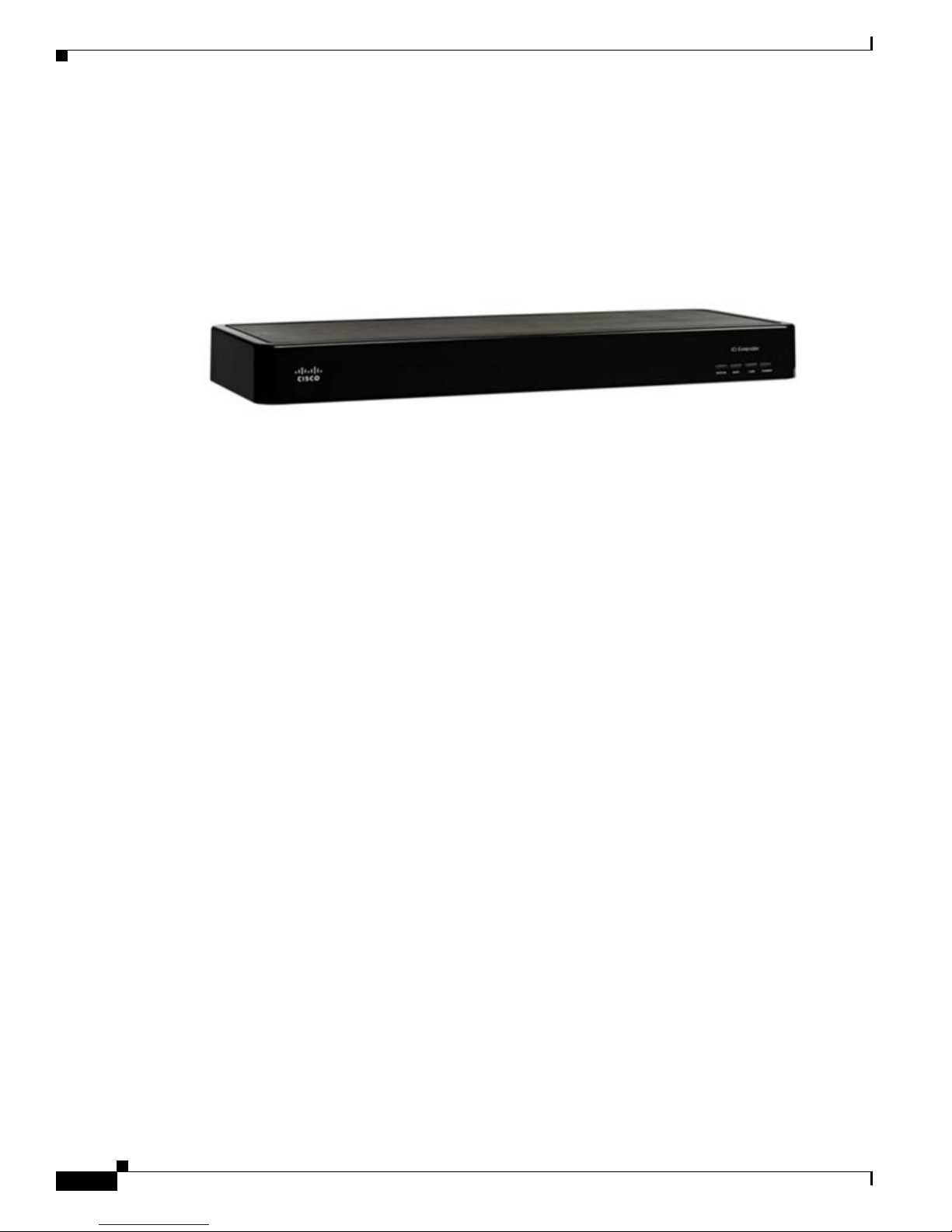
The Cisco Smart+Connected I/O Extender provides additional ports for controlling home theaters, video
devices, motion sensors, and other devices that use infrared (IR), serial, contact, and relay connections.
When paired with a Cisco Smart+Connected Residential Controller, the Cisco I/O Extender is ideal for
expanding control in large, multiroom residences or for residences with numerous devices.
Figure 1 Cisco I/O Extender
The Cisco I/O Extender provides the following features:
• Includes eight IR and four serial outputs.
• Eight contacts and eight relays for expanded control in large residences.
• Makes it possible to easily add control capability to new or existing systems.
• Flexible rack or wall mounting options.
• Provides expanded control options for exceptional value.
Package Contents
The following items are included in your Cisco I/O Extender box:
• Cisco I/O Extender
• Power cord
• 6 IR Emitters
• 4 Pluggable Contact/Relay Connectors
• 1U Rack Mount Ears
• Warranty Card
Cisco Smart+Connected I/O Extender Reference Guide
2
OL-27368-01
Page 3

Requirements
Prior to installing this product, ensure that: Ethernet network wiring is in installed and functioning.
Mounting Options
Before installing the Cisco I/O Extender, mount the device using one of the following options.
• Place it on a flat surface
• Mount it on the wall
• Mount it on a rack—front facing or back facing
Flat Surface
Place the device on a flat surface, and connect the devices.
Mount on a Wall (New Construction)
Requirements
Mount in a Rack
Step 1 Screw the rack mount ears to the front of the device.
Step 2 Screw the device to the front of the rack.
Step 1 Screw the rack mount ears to the back of the device.
Step 2 Screw the device to the rails on the rack. If your rack has rear rails, this may be your best option.
The device can mount to a 2-gang wall box.
• Mount the 2-gang wall box.
• Hang the device on the two (2) screws in the wall box front side up.
• Connect the devices at the bottom of the device.
Front of Rack
Back of Rack
OL-27368-01
Cisco Smart+Connected I/O Extender Reference Guide
3
Page 4
Installation Instructions
Installation Instructions
To install the Cisco I/O Extender, follow these general steps:
Procedure
Step 1 Ensure that your residential network is in place before starting your syst em setup, including your Cisco
Controller: The Cisco I/O Extender requires a network connection to use all output ports as designed.
When connected, the Cisco I/O Extender can access web-based media databases and the Cisco
Controller.
Step 2 Connect the Cisco I/O Extender to the network: To connect using an Ethernet connection, plug the da ta
cable from the network connection into the Cisco I/O Extender RJ-45 port (labeled “Ethernet”).
Step 3 Power up the Cisco I/O Extender: Plug the Cisco I/O Extender power cord (provided) into the Cisco I/O
Extender power plug port and then to an electrical outlet.
Step 4 Connect the system devices: Follow the steps described in the “Connecting the Devices” on page 6 .
Front View (LEDs and Other Features)
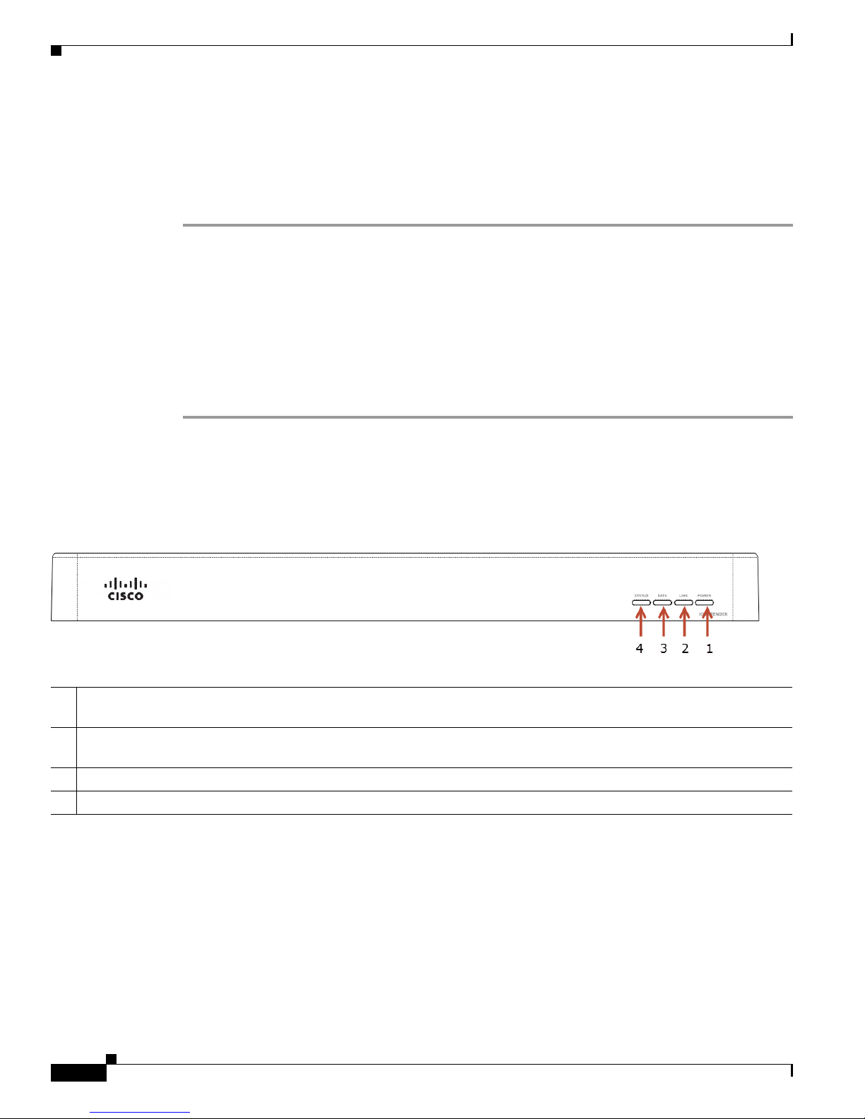
Figure 2 Front View
1 Power LED—Blue light indicates AC power is present. The device turns on immediately after power is applied to the
device.
2 Link/Identification LED— Blue LED light indicates that the Cisco I/O Extender has been identified in a Composer Pro
project. Use this button also to identify the device.
3 Data LED—Blue LED light indicates activity.
4 Status LED—Red, Orange, and Blue blinking lights indicate the status during startup.
Cisco Smart+Connected I/O Extender Reference Guide
4
OL-27368-01
Page 5
Rear View (Input and Output Ports)
Rear View (Input and Output Ports)
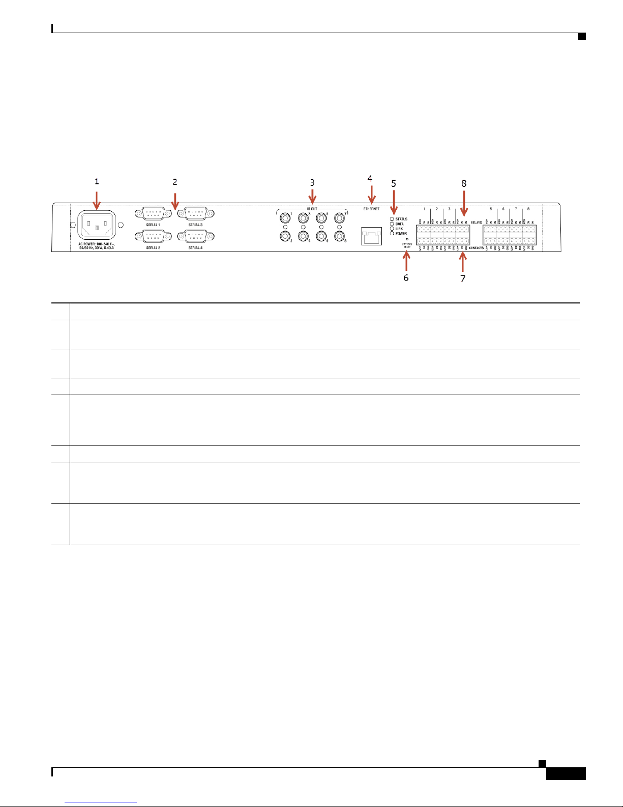
Connect all applicable devices to the Cisco I/O Extender using the connection options described in the
following figure.
Figure 3 Rear View
1 Power plug port—AC power receptacle for an IEC 320 power cord.
2 Serial Out—Four (4) serial output ports for DB9 (receivers, disc changers, etc.). See the “Connect the Serial Ports”
section on page 9 for more information.
3 IR Output—Eight (8) IR output 3.5 mm ports for up to eight (8) IR output transmitters. See the “Setting Up IR Emitters
or IR Blaster” section on page 9 for more information.
4 Ethernet—One (1) RJ-45 port for a 10/100 BaseT Ethernet connection.
5 LED Indicators—Status, Data, Link, Power.
The LEDs on the front and back of the device are the same.
See the “Front View (LEDs and Other Features)” section on page 4 for details.
6 Reset Button—Recessed Reset button. Use the end of a paper clip to press and reset the device.
7 Contacts (8 sets, Bottom Row)—Pluggable terminal block connectors for eight (8) dry contact closures, logic input
connections, Door Contact Sensors, or Motion Sensors. Provides power for small devices (12 V), signal input (SIG),
return path (GND). The current, 1250 mA, is shared across all eight (8) sets of contacts.
8 Relays (8 sets, Top Row)—Pluggable terminal block connector for eight (8) normally closed or normally opened
switchable connections, such as a blind, a fireplace, or a projector screen. The set contains a connection for Normally
Opened (NO), Normally Closed (NC), and Common (COM). Relays are rated for 24 V 6 A maximum operation.
OL-27368-01
Cisco Smart+Connected I/O Extender Reference Guide
5
Page 6

Connecting the Devices
Connecting the Devices
Tip Use Composer Pro to step through the connection process before or after the Cisco Controller is
physically connected.
Connect all applicable devices to the Cisco I/O Extender using one of the connection options described
in the “Rear View (Input and Output Ports)” section on page 5.
Pluggable Terminal Block Connectors
For the contact and relay ports, the Cisco I/O Extender makes use of a pluggable terminal block
connector—a removable plastic part that locks in individual wires (included).
To connect a device to the pluggable terminal block:
Procedure
Step 1 Insert one of the wires required for your device into the appropriate opening in the pluggable terminal
block you reserved for that device (
Step 2 Insert the wire as follows:
• If using solid core wire, push the wire into the hole below the slotted retention tab, and ensure that
it’s tightly secured.
• If using stranded wire, push the slotted retention tab in using a small flat-blade screwdriver. Insert
the wire into the hole below the tab, and then release the tab to secure the wire (
Figure 4 Insert Wires into the Connectors
Figure 4).
Figure 4).
For example, if you add a Motion Sensor, connect its wires to the following Contact openings—power
input to +12V output signal to SIG, and ground connector to GND. See the “Connect to the Contact Port”
on page 7 or the “Connect to the Relay Port” on page 8 to learn how to connect the devices.
Step 3 Repeat Steps 1 and 2 for all wires required for your device.
Cisco Smart+Connected I/O Extender Reference Guide
6
OL-27368-01
Page 7
Note If you connect dry contact closure devices, such as door switches, connect the switch between +12V
(Power) and SIG (Signal).
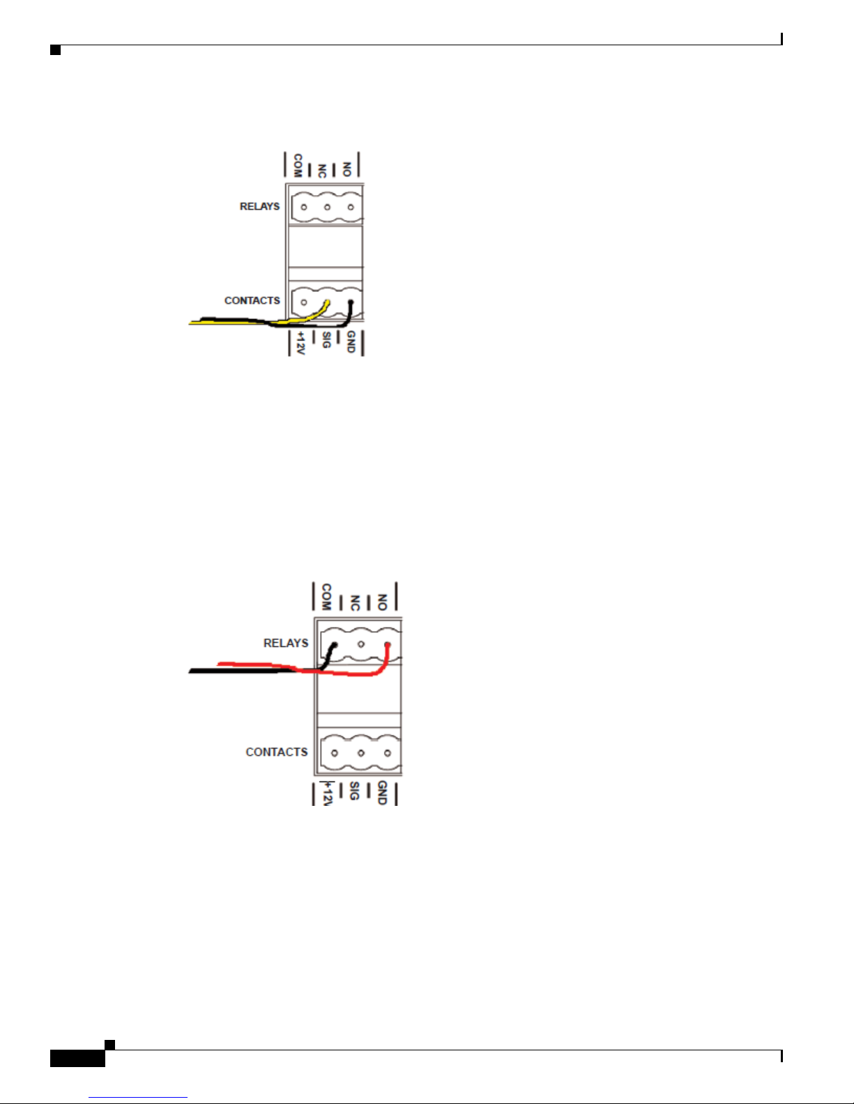
Connect to the Contact Port
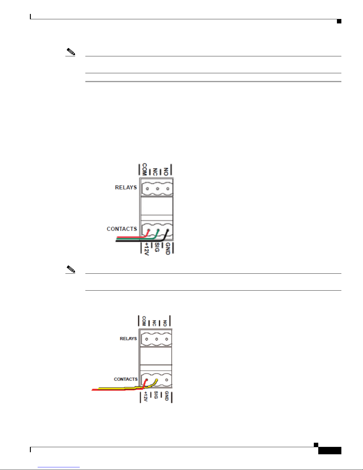
The Cisco I/O Extender provides four (4) contact ports for the pluggable terminal block provided.
See Figure 5 through Figure 7 to learn how to connect the device to a contact port.
Figure 5 Contact Port for Voltage Source (e.g., Motion Sensor)
Connecting the Devices
OL-27368-01
Note +12V and GND are used to power the Motion Sensor. SIG and GND are used to detect the state of the
Contact in the Motion Sensor.
Figure 6 Contact for Dry Contact (e.g., Door Contact Sensor)
Cisco Smart+Connected I/O Extender Reference Guide
7
Page 8
Connecting the Devices
Figure 7 Contact for Self-Powered Voltage Source Device
Connect to the Relay Port
The Cisco I/O Extender provides eight (8) relay ports.
For most applications, attach one (1) wire to the common terminal, and the other to the normally open
terminal. The Relay switches close when the Relay is activated. The Cisco I/O Extender can support
applications that require a normally closed Contact.
Figure 8 Relay Port, Normally Open
Cisco Smart+Connected I/O Extender Reference Guide
8
OL-27368-01
Page 9

Figure 9 Relay Port, Normally Closed
Connect the Serial Ports
Configuring the Cisco I/O Extender
The Cisco I/O Extender provides four (4) DB9-style serial ports that use the RS-232 protocol. Connect
a device to the Cisco I/O Extender—for example, a receiver or disc changer—by aligning the pins,
inserting the plug and tightening the screws. Serial ports support many different baud rates. All ports
support Odd, Even and No Parity and hardware flow control.
Setting Up IR Emitters or IR Blaster
Your system may contain third-party products that are controlled through IR commands (usually using
remote controls). To provide a way for the Cisco Controller to control a device that only recognizes IR
commands, complete the following:
Procedure
Step 1 Plug the 3.5 mm connector end of one of the 4 IR stick-on emitters provided into an IR Out port on the
Cisco I/O Extender.
Step 2 Place the stick-on emitter end over the IR receiver on the Media Player, TV, or other target device to
drive IR signals from the Cisco I/O Extender to the target.
Configuring the Cisco I/O Extender
After you install and connect the hardware, use the Composer Pro software to configure the devices and
customize the system.
See the Cisco Smart+Connected Residential Installation and Configuration Guide for more information.
OL-27368-01
Cisco Smart+Connected I/O Extender Reference Guide
9
Page 10

Resetting the Device
Resetting the Device
Procedure
To reset the Cisco I/O Extender for system recovery, perform the following steps:
Step 1 On the back of the device insert the end of a paper clip into the small hole (to the right of the Ethernet
connector).
Step 2 Power cycle the device by pressing and holding the Reset button for about 5-7 seconds and the Status LED
blinks orange. This action starts the recovery process.
Using the Identification Button
• To reset the device to the network defaults, power cycle the Cisco I/O Extender (using the power
button on the front of the device) and hold the Identification button until the Data, Link, and Power
LEDs are solid blue; immediately release the button.
• If during the boot sequence, the Status LED stays Orange, press and hold the Identification button
until the LED blinks Blue, and then release it.
Specifications
Table 1 Cisco I/O Extender Specifications
Basic Specifications Description
Status LEDs 4
Serial Ports (Male DB9 RS232) 4
IR Outputs 8
Contacts 8
Relays 8
Network Connectivity 10/100 BaseT Ethernet
Power Supply 100–240 VAC
Amps 0.55 A
Hertz 50–60 Hz
Watta g e 30W
Dimensions (H x W x D) 1.59 in. × 16.84 in. × 6.34 in.
Weight 4.8 lb. (2.18 kg)
Power Cord 1
IR Emitter Cables 6
Rack Ears Included
(40.39 mm × 427.74 mm × 161.04 mm)
Cisco Smart+Connected I/O Extender Reference Guide
10
OL-27368-01
Page 11

Regulatory/Safety Information
Table 1 Cisco I/O Extender Specifications (continued)
Normal operating temperature 32°F to 104°F (0°C to 40°C)
Storage temperature –4°F to 149°F (–20°C to 65°C)
Regulatory/Safety Information
To review regulatory information, go to www.cisco.com/go/smartconnectedresidential/docs.
Related Documentation
For more information about the Cisco Smart+Connected Residential products, see the following
documents and websites:
Subject / Document Title Location
General
Product Information and Home Page
Cisco 1-Year Limited Hardware Warranty Terms www.cisco.com/go/smartconnectedresidential
Regulatory Compliance and Safety Information for Cisco Smart+Connected
Residential Products
Cisco Support www.cisco.com/cisco/web/support/
Technical Documentaion
Installation and Configuration
Cisco Smart+Connected Residential Installation and Configuration Guide
www.cisco.com/go/smartconnectedresidential
warranty
www.cisco.com/go/smartconnectedresidential/
docs
www.cisco.com/go/smartconnectedresidential/
docs
Cisco RMS Installation and Administration
Cisco Smart+Connected Remote Management Console Administration
Guide
Cisco Smart+Connected Remote Management Server Installation Guide
Reference Guides
Cisco Smart+Connected Controller 200 Reference Guide
Cisco Smart+Connected Controller 250 Reference Guide
Cisco Smart+Connected Controller 800 Reference Guide
Cisco Smart+Connected 7” In-wall Display Reference Guide
Cisco Smart+Connected Portable Tablet Reference Guide
Cisco Smart+Connected I/O Extender Reference Guide
Cisco Smart+Connected Universal Remote 150 Reference Guide
Cisco Smart+Connected Universal Remote 250 Reference Guide
Cisco Smart+Connected Video Door Station Reference Guide
Cisco Smart+Connected I/O Extender Reference Guide
OL-27368-01
11
Page 12

Warranty
Cisco Smart+Connected Residential Licensing Guide See your Cisco representative or partner for
more information.
Smart Device Compatibility and other information:
www.cisco.com/go/smartconnectedresidential
Cisco Smart+Connected Smart Device License for Real Estate Developers
Composer Pro User Guide http://www.control4.com/documentation/Com
poser_Pro_User_Guide/index.htm
Warranty
A Cisco 1-year warranty applies. Go to the following URL for more information:
www.cisco.com/go/smartconnectedresidentialwarranty
Service and Support
Cisco offers a wide range of support programs to accelerate customer success. These innovative
programs are delivered through a unique combination of people, processes, tools, and partners, resulting
in high levels of customer satisfaction. For more information, contact your Cisco sales representative or
go to www.cisco.com/cisco/web/support/index.html
This document is to be used in conjunction with the documents listed in the “Related Documentation” section.
Cisco and the Cisco logo are trademarks or registered trademarks of Cisco and/or its affiliates in the U.S. and other countries. To view a list of
Cisco trademarks, go to this URL: www.cisco.com/go/trademarks. Third-party trademarks mentioned are the property of their respective owners. The
use of the word partner does not imply a partnership relationship between Cisco and any other company. (1110R)
Any Internet Protocol (IP) addresses and phone numbers used in this document are not intended to be actual addresses and phone numbers. Any
examples, command display output, network topology diagrams, and other figures included in the document are shown for illustrative purposes only.
Any use of actual IP addresses or phone numbers in illustrative content is unintentional and coincidental.
© 2012 Cisco Systems, Inc. All rights reserved.
Cisco Smart+Connected I/O Extender Reference Guide
12
OL-27368-01
Page 13

Service and Support
OL-27368-01
Cisco Smart+Connected I/O Extender Reference Guide
13
Page 14

Service and Support
Cisco Smart+Connected I/O Extender Reference Guide
14
OL-27368-01
 Loading...