

Page 1
Cisco Smart+Connected Controller 200
Reference Guide
This document provides information about the available ports, technical specifications and features of
the Cisco Smart+Connected Controller 200 (SCH-CONTROL-200).
• Overview, page 2
• Package Contents, page 2
• Mounting the Cisco Controller 200 on a Wall, page 3
• Front View (LEDs and Other Features), page 5
• Rear View (Input and Output Ports), page 6
• Connecting Devices, page 6
• Connecting the IR Ports/Serial Ports (Optional), page 8
• Setting Up External Storage Device (Optional), page 9
• Configuring the Cisco Controller 200, page 9
• Restoring the Device to the Factory Settings, page 9
• Resetting the Device Network Settings, page 9
• Regulatory/Safety Information, page 10
• Specifications, page 10
• Related Documentation, page 11
• Warranty, page 12
• Service and Support, page 12
Americas Headquarters:
Cisco Systems, Inc., 170 West Tasman Drive, San Jose, CA 95134-1706 USA
Page 2

Overview
Overview
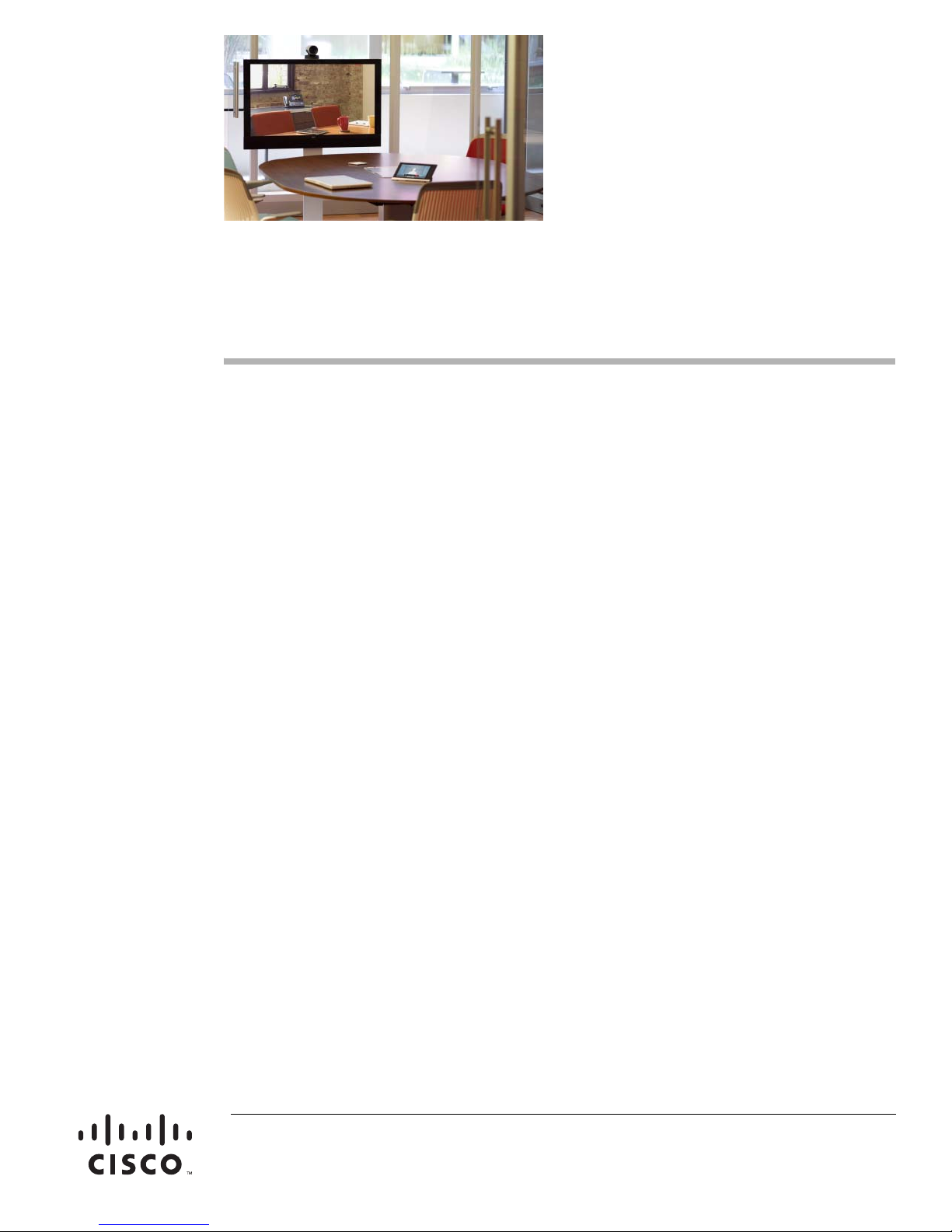
The Cisco Smart+Connected Controller 200 provides intelligent control for the Cisco Smart+Connected
Residential Solution, allowing residents to manage lighting, security, temperature, and multimedia,
while also providing a portal into the community from the residence. The Cisco Controller 200 integrates
a broad range of devices using a variety of protocols (Internet Protocol [IP], ZigBee HA, infrared [IR],
serial, and more). By combining wired and wireless technologies, the Cisco Controller 200 provides
flexibility in extending the capabilities of the Cisco Smart+Connected Residential Solution to any device
located anywhere in the residence. All of these services can be controlled through simple and intuitive
touchscreen displays or on-screen TV navigators managed through one of the Cisco Smart+Connected
Universal Remotes.
While individual Cisco Controllers can support a single room or small residence, additional Cisco
Controllers can be added to provide on-screen TV navigation in other rooms. Cisco Controllers can also
be added in groups to provide coordinated control throughout a large residence or building. These
compact devices are easy to mount behind a TV or on a wall, so that residents can enjoy the power of
on-screen control virtually anywhere.
Figure 1 Cisco Controller 200
Features and Benefits
The Cisco Controller 200 is an entry-level device for one-room residential units where digital
high-definition multimedia interface (HDMI) output to the TV is not required. In larger installations, the
Cisco Controller 200 can be used as an auxiliary Cisco Controller to support on-screen TV navigation
in additional rooms, to offload processing tasks, or to act as a ZigBee Access Point (ZAP).
Package Contents
The following items are included in the Cisco Controller 200 box:
• Cisco Smart+Connected Controller 200
• AC to DC power adapter with power cord
• IR emitters (4)
• Universal Mounting Plate
• Screws (4)
Cisco Smart+Connected Controller 200 Reference Guide
2
OL-27357-01
Page 3
Mounting the Cisco Controller 200 on a Wall
Note This document, and other related documents, are available online at
www.cisco.com/go/smartconnectedresidential/docs. See the “Related Documentation” section on
page 11 for more information.
Mounting the Cisco Controller 200 on a Wall
The Cisco Controller 200 can be mounted on a wall or placed on a horizontal surface (such as a shelf).
Procedure
To mount the device on a wall:
Step 1 Select one of the following mounting options:
• Mount the Controller 200 horizontally using one (1) standard single-gang wall box. The wall
mounting plate has four (4) horizontal sets of slots. Leave the screws protruding .08” from the wall.
• Mount the Controller 200 horizontally or vertically using one (1) standard double-gang box. Leave
the screws protruding .08” from the wall.
• Mount the Cisco Controller 200 horizontally or vertically using four (4) screws (not provided)
placed directly into a wall stud or studs.
–
Using the mounting plate as a template, screw four (4) screws into a stud to align with the four
(4) center slots for vertical positioning; or into two (2) studs to align with the four (4) corner
slots for horizontal positioning.
–
Leave the screws protruding .08” from the wall.
Note To quickly check the fit of the screws, place the wall mounting plate over the screws before
attaching it to the bottom of the Controller 200.
OL-27357-01
Cisco Smart+Connected Controller 200 Reference Guide
3
Page 4
Mounting the Cisco Controller 200 on a Wall
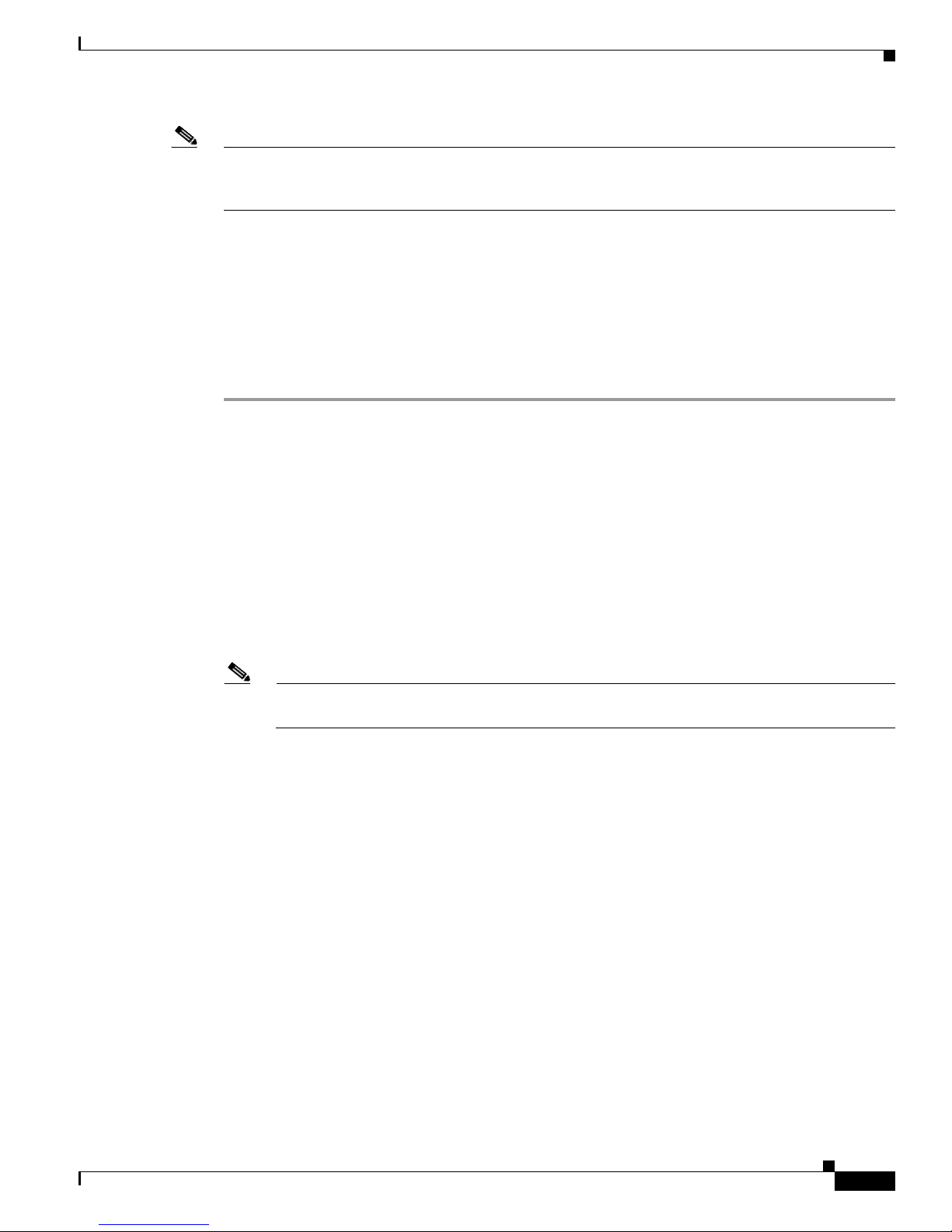
Figure 2 Mounting the Cisco Controller 200
1 Slots to horizontally mount the Controller 200
2 Holes for attaching the plate to the Controller 200
3 Slots to vertically mount the Controller 200
Step 2 Use the four (4) screws (provided) to attach the mounting plate to the bottom of the Controller 200.
Ensure that the narrow end of the slots will be on top when the device is installed.
Step 3 Arrange the wires to fit in the wire channels on the mounting plate.
Step 4 Line the slots on the mounting plate up with the screws.
Step 5 Press the device onto the screws and slide down until the screws are in the narrow end of the slots.
Cisco Smart+Connected Controller 200 Reference Guide
4
OL-27357-01
Page 5

Front View (LEDs and Other Features)
Front View (LEDs and Other Features)
Figure 3 Front View
1 IR Window / IR Blaster—For capturing third-party IR codes from hand-held devices (such as remote controls) or
blasting IR codes. The Wi-Fi LED blinks red when capturing IR codes.
2 Wi-Fi LED—The Wi-Fi LED blinks orange and then blue during the boot process. When the operating system is
running, the Wi-Fi driver changes the LED color depending on the signal strength of its connection to its associated
access point. Colors and signal strength are:
• orange=fair to good
• blue=excellent
• no light=no connection.
3 Data LED—Blue LED indicates streaming audio is received.
4 Link LED/Identification button—Blue LED light indicates that the Controller 200 has been identified in a Composer
Pro project. Press this button to identify this device in Composer Pro.
5 Power LED—Blue LED light indicates AC power is present. This LED turns on immediately after the power is applied
to the device.
6 Factory Restore Button (bottom of device)—Restores the Controller 200 to the factory default settings. See the
“Restoring the Device to the Factory Settings” section on page 9.
OL-27357-01
Cisco Smart+Connected Controller 200 Reference Guide
5
Page 6

Rear View (Input and Output Ports)
Rear View (Input and Output Ports)
Figure 4 Rear View
1 Audio In (1)—3.5 mm jacks for stereo channel input (line level) for one stereo analog source.
2 Audio Out (1 left-right pair)—RCA jacks for stereo channel line output (line level) for amplifiers or audio switches.
3 Video Out—Composite RCA and Component RCA jacks.
4 Serial Port (up to 2) or IR Out (up to 4)—3.5 mm jacks for up to 4 IR emitters or for a combination of IR emitters
and serial devices (up to 2). Jacks 1 and 2 can be configured independently for serial devices, such as receivers or disc
changers (requires serial cable, sold separately.)
5 USB (1 port)—For external storage device with USB support (such as FAT32-formatted devices) or Wi-Fi adapter.
6 Ethernet—RJ-45 jack for a 10/100 Base T Ethernet connection.
7 Power plug port—DC power supply port.
Connecting Devices
Note Use the Composer Pro software to step through the connection process before or after the physical
connections are completed. See the
Guide for more information.
Connect all applicable devices to the Controller 200 using the connection options described in the
following table.
Table 1 Connections Options
Port Description
Audio In (1)
Audio Out (1 left-right
pair)
One 3.5 mm jack for stereo channel input (line level) for one stereo
analog source.
Two RCA jacks for stereo channel line output (line level) for
amplifiers or audio switches.
Cisco Smart+Connected Residential Installation and Configuration
Cisco Smart+Connected Controller 200 Reference Guide
6
OL-27357-01
Page 7

Table 1 Connections Options
Port Description
Video Out Options
Composite or component ports for displaying navigation menus on a
monitor or TV. Use the component jack to display either standard or
high-definition video. Use the composite port to display standard
definition video.
Note The default video output mode is NTSC over composite. In
this mode, some bleed-through of the NTSC signal on the
component video output connections occurs. However, the
video image will not appear correctly in this mode. The Cisco
Controller 200 can be configured to output over component
using NTSC (standard definition) or 720p (high definition).
To configure the video mode to use the component video
outputs, make the appropriate bindings for the desired video
output mode in Composer Pro.
Serial Port (up to 2) or
IR Out (up to 4)
3.5 mm jacks for up to four IR emitters. These ports can also be used
for a combination of IR emitters and up to two serial devices.
Ports 1 and 2 can be configured independently for serial devices, such
as receivers or disc changers. See the “Setting Up IR Emitters or IR
Blaster” section on page 8 for more information.
USB (1 port)
Used to connect an external USB storage device (such as
FAT32-formatted devices).
See the “Setting Up External Storage Device (Optional)” section on
page 9 for more information.
Ethernet
A RJ-45 for a 10/100 BaseT Ethernet connection to the dwelling
network.
Connecting Devices
Power Plug
OL-27357-01
For use with the included DC power supply.
Cisco Smart+Connected Controller 200 Reference Guide
7
Page 8

Connecting the IR Ports/Serial Ports (Optional)
Connecting the IR Ports/Serial Ports (Optional)
The Cisco Controller 200 provides 4 IR ports.
Ports 1 and 2 can be reconfigured for serial communication to connect serial devices such as a receiver
or disc changer. A special cable is required (not included). Any jack not used for serial can be used for
IR.
Serial ports support many different baud rates. The following table shows the serial communication
values.
Ta b le 2 I R / S e r i a l P o rt s
Hardware Flow
Control Odd Parity Even Parity No Parity Other
Serial Port 1 X X X
Serial Port 2 X X X
Serial Port 3 X 8 bits/char; 1 stop bit
Serial Port 4 X 8 bits/char; 1 stop bit
Setting Up IR Emitters or IR Blaster
Your system may contain third-party products that are controlled with IR commands (usually through
remote controls). To enable the Controller 200 to control a device that only recognizes IR commands,
complete one of the following procedures for IR Emitters or IR Blaster.
IR Emitter Procedure
Step 1 Plug the 3.5 mm connector end of one of the 4 IR stick-on emitters provided into an IR Out port on the
Controller 200.
Step 2 Place the stick-on emitter end over the IR receiver on the Media Player, TV, or other target device to
drive IR signals from the Controller 200 to the target.
IR Blaster Procedure
In addition to IR emitters, the Cisco Controller 200 is also equipped with an IR blaster, which is located
just left of the front LEDs. To use the blaster instead of an IR emitter, do the following:
Step 1 In Composer Pro, connect the Front IR Out of the Controller 200 to the IR In of the device you want to
control.
Step 2 Test and verify that the Controller 200 is positioned in such a way that the blaster can reach the device
you want to control.
Cisco Smart+Connected Controller 200 Reference Guide
8
OL-27357-01
Page 9

Setting Up External Storage Device (Optional)
Setting Up External Storage Device (Optional)
To store and access media from an external storage device, such as a network hard drive or USB memory
device, attach the USB drive to the Cisco Controller USB port and configure or scan the media from
Composer Pro.
See the Cisco Smart+Connected Residential Installation and Configuration Guide for more information.
Configuring the Cisco Controller 200
After you install and connect the hardware (such as a touchscreen, TV, lights, etc.), use the Composer
Pro software to configure the devices and customize the system.
See the Cisco Smart+Connected Residential Installation and Configuration Guide for more information.
Restoring the Device to the Factory Settings
Complete the following procedure to the Cisco Controller 200 system or the factory default image.
Caution This action deletes the Composer Pro project.
Procedure
Step 1 On the bottom of the device, insert the end of a paper clip into the small hole.
Step 2 Power cycle the device while pressing and holding the Factory Restore button for about 5-7 seconds and
the Status (Wi-Fi) LED blinks orange. This action starts the recovery process.
Resetting the Device Network Settings
Complete the following procedure to reset the Cisco Controller 200 to the network defaults.
Procedure
Step 1 Power cycle the Cisco Controller and press the Identification button on the front of the device until the
Data, Link, and Power LEDs are solid blue; immediately release the button.
Step 2 If during the boot sequence, the Status LED stays Orange, press and hold the Identification button until
the LED blinks blue, and then release it.
Tip If the Cisco Controller is connected to a TV, a message will appear indicating when to let go of
the button.
OL-27357-01
Cisco Smart+Connected Controller 200 Reference Guide
9
Page 10

Regulatory/Safety Information
Regulatory/Safety Information
To review regulatory information, go to www.cisco.com/go/smartconnectedresidential/docs.
Specifications
Table 3 Cisco Controller 200 Specifications
Basic Specifications Description
Audio/Video Inputs and Outputs
HDMI out (Digital audio and on-screen navigator) N/A
Component video out 1 (720p Only)
Composite video out 1 (480i)
Analog audio out 1 (L/R RCA)
Analog audio input to convert to digital 1 (3.5 mm connector)
Digital audio out: Coax (RCA) N/A
Total number of audio outputs 1
Network
Ethernet ports × speed 1 × 10/100
ZigBee Pro Yes (supports ZigBee Pro HA profile)
ZigBee antenna Internal
USB 2.0 1
Control
IR outputs for individual device control (3.5 mm) 4 (includes 4 IR emitters)
IR blaster for multiple device control (front) Yes
IR Input (Used for IR Learning) Yes
RS-232 for serial controlled devices Yes
Environmental
Normal operating temperature 32°F to 104°F (0°C to 40°C)
Storage temperature -4° F to 149° F (-20° C to 65° C)
Mounting Options
Shelf (with A/V gear) Yes
Wall/TV mount Yes (included)
Dimensions (H×W×D) 1.44 in. x 8.55 in. x 5 in.
Power
Power supply External
Power supply Input: 100–240V, 50–60 Hz
(36.5 mm x 217 mm x 127 mm)
Cisco Smart+Connected Controller 200 Reference Guide
10
OL-27357-01
Page 11

Related Documentation
Related Documentation
For more information about the Cisco Smart+Connected Residential products, see the following
documents and websites:
Subject / Document Title Location
General
Product Information and Home Page
Cisco 1-Year Limited Hardware Warranty Terms www.cisco.com/go/smartconnectedresidential
Regulatory Compliance and Safety Information for Cisco Smart+Connected
Residential Products
Cisco Support
Technical Documentaion
Installation and Configuration
Cisco Smart+Connected Residential Installation and Configuration Guide
Cisco RMS Installation and Administration
Cisco Smart+Connected Remote Management Console Administration
Guide
www.cisco.com/go/smartconnectedresidential
warranty
www.cisco.com/go/smartconnectedresidential/
docs
www.cisco.com/cisco/web/support/
www.cisco.com/go/smartconnectedresidential/
docs
Cisco Smart+Connected Remote Management Server Installation Guide
Reference Guides
Cisco Smart+Connected Controller 200 Reference Guide
Cisco Smart+Connected Controller 250 Reference Guide
Cisco Smart+Connected Controller 800 Reference Guide
Cisco Smart+Connected 7” In-wall Display Reference Guide
Cisco Smart+Connected Portable Tablet Reference Guide
Cisco Smart+Connected I/O Extender Reference Guide
Cisco Smart+Connected Universal Remote 150 Reference Guide
Cisco Smart+Connected Universal Remote 250 Reference Guide
Cisco Smart+Connected Video Door Station Reference Guide
Cisco Smart+Connected Residential Licensing Guide See your Cisco representative or partner for
more information.
Smart Device Compatibility and other information:
Cisco Smart+Connected Smart Device License for Real Estate Developers
Composer Pro User Guide http://www.control4.com/documentation/Com
www.cisco.com/go/smartconnectedresidential
poser_Pro_User_Guide/index.htm
OL-27357-01
Cisco Smart+Connected Controller 200 Reference Guide
11
Page 12

Warranty
Warranty
A Cisco 1-year warranty applies. Go to the following URL for more information:
www.cisco.com/go/smartconnectedresidentialwarranty
Service and Support
Cisco offers a wide range of support programs to accelerate customer success. These innovative
programs are delivered through a unique combination of people, processes, tools, and partners, resulting
in high levels of customer satisfaction. For more information, contact your Cisco sales representative or
go to www.cisco.com/cisco/web/support/index.html
This document is to be used in conjunction with the documents listed in the “Related Documentation” section.
Cisco and the Cisco Logo are trademarks of Cisco Systems, Inc. and/or its affiliates in the U.S. and other countries. A listing of Cisco's trademarks
can be found at www.cisco.com/go/trademarks. Third party trademarks mentioned are the property of their respective owners. The use of the word
partner does not imply a partnership relationship between Cisco and any other company. (1005R)
Any Internet Protocol (IP) addresses and phone numbers used in this document are not intended to be actual addresses and phone numbers. Any
examples, command display output, network topology diagrams, and other figures included in the document are shown for illustrative purposes only.
Any use of actual IP addresses or phone numbers in illustrative content is unintentional and coincidental.
© 2012 Cisco Systems, Inc. All rights reserved.
Cisco Smart+Connected Controller 200 Reference Guide
12
OL-27357-01
 Loading...