

Page 1
Cisco Smart+Connected 7" In-wall Display
Reference Guide
This document provides additional information about the features of the Cisco Smart+Connected 7"
In-wall Display (SCH-7IN-TS-B/W).
Refer to the following topics for more information:
• Overview, page 2
• Package Contents, page 3
• Requirements, page 3
• Back Box Options, page 4
• Device Illustrations and Descriptions, page 6
• Touchscreen Placement, page 7
• LED Indicator, page 8
• Installation, page 8
• Power Installation, page 12
• Configuration, page 15
• Troubleshooting, page 16
• Restore to Factory Default, page 16
• Specifications, page 20
• Regulatory/Safety Information, page 21
• Related Documentation, page 21
• Warranty, page 22
• Service and Support, page 22
Americas Headquarters:
Cisco Systems, Inc., 170 West Tasman Drive, San Jose, CA 95134-1706 USA
Page 2
Overview
Overview
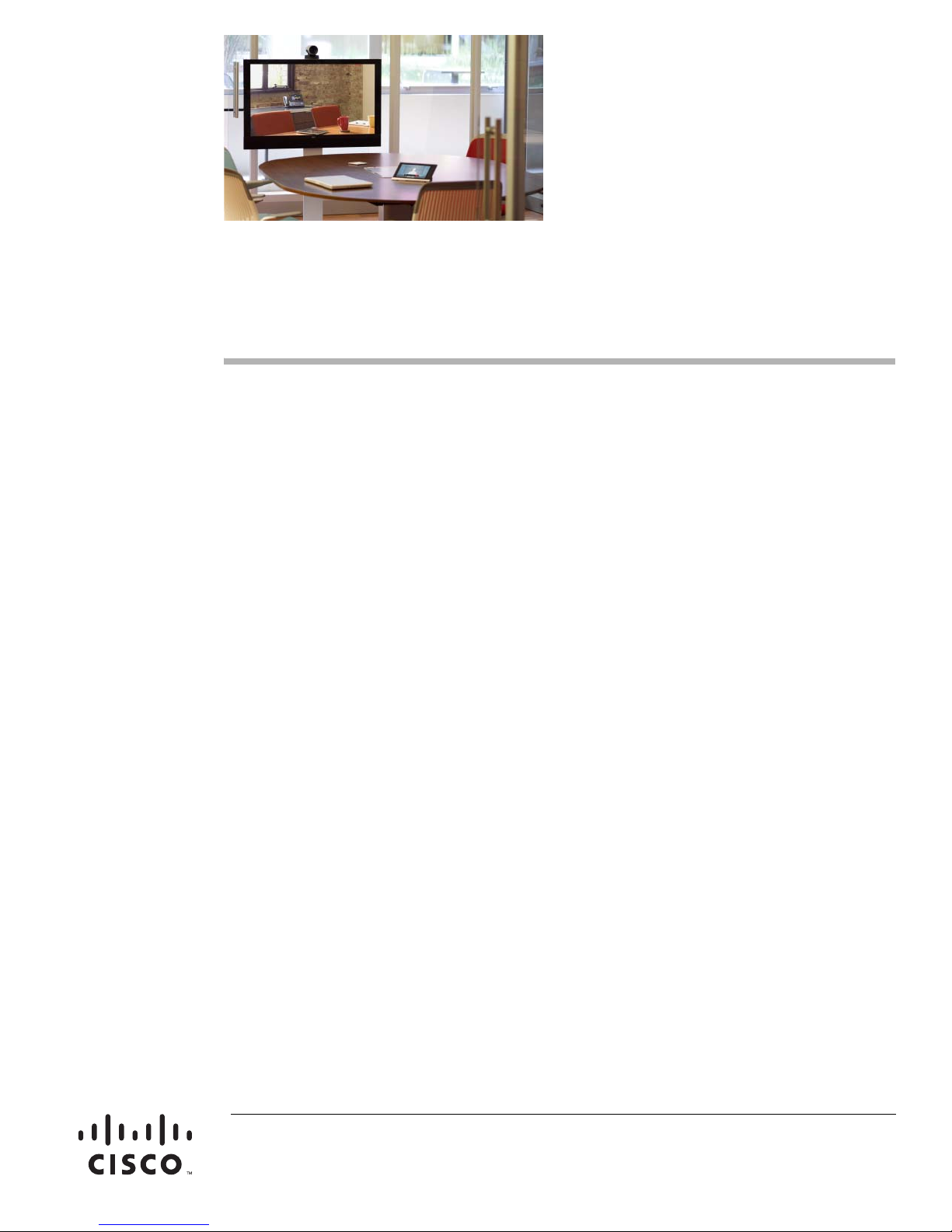
The Cisco Smart+Connected 7" In-wall Display is a stylish way to offer total control where the resident
needs it most, such as next to the front door, in the kitchen, or in the living room. Since the Cisco In-wall
Display supports both Ethernet and Wi-Fi connectivity, it can be securely mounted in any area of the
residence to provide consistent and reliable network access. The Cisco In-wall Display also supports
Power over Ethernet (PoE), allowing the device to receive power directly from the Ethernet cable,
eliminating the need for a separate power connection. Residents can also use the built-in camera to view
video from a Cisco Video Door Station or from the lobby (note that the Cisco Video Door Station is a
separate product that must be purchased separately.) Features include:
• Integrated camera with full-motion video for high-quality audio and video communications with the
Cisco Smart+Connected Video Door Station and Cisco Portable Tablet.
• Audio and video intercom integration with other Cisco In-wall Displays and Cisco Portable Tablets
installed in the residence.
• Sleek look and feel with edge-to-edge capacitive glass and low-profile.
• Four customizable buttons allow one touch to set a scene (for example, a sleep scene could turn off
the lights, reduce the temperature, and lock the doors).
• G.722 wideband audio intercom featuring beamforming microphones for crystal-clear
communications.
• Flexible power (AC or Power over Ethernet) and network connectivity (Ethernet or Wi-Fi) options.
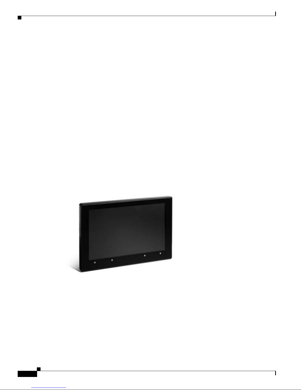
Figure 1 Cisco In-wall Display
The available network and power options are:
• Option 1: Ethernet with PoE—The Ethernet network connection is provided through the PoE
Injector. No additional wiring is needed.
• Option 2: Ethernet with AC—Connect the touchscreen to one of the RJ-45 LAN ports on the
gateway/router using the RJ-45 Ethernet cable.
• Option 3: Wi-Fi with AC—The internal Wi-Fi will communicate with the LAN’s WAP. If the LAN
has a WAP set up, no additional wiring is needed.
Cisco Smart+Connected 7" In-wall Display Reference Guide
2
OL-27263-01
Page 3

Note Video intercom using 802.11b is not recommended or supported for video intercom. We recommend
Wireless-N for video intercom. See “Wireless Network Limitations” and “Power and Network
Installation Options.”
Package Contents
Carefully unpack the Cisco In-wall Display and ensure the following items are included in the box.
Caution Do not apply excessive pressure to the touchscreen display during handling. Doing so can crack the
screen and damage the touchscreen.
• Cisco In-wall Display with camera
• Power box (used to power the touchscreen)
• Two (2) screws to attach the power box
• Warranty card
Package Contents
Requirements
To install the Cisco In-wall Display, the following is required:
• A Cisco Controller fully installed and configured.
• A custom Back Box installed. See the “Back Box Options” section on page 4.
• If using Ethernet with PoE power:
–
–
–
• If using Ethernet with AC power:
–
–
–
–
• If using wireless with AC power:
–
–
–
Ethernet network installed and available that includes a gateway/router/switch.
A third-party PoE Injector or switch (certified to UL/ANSI standards).
Two (2) Ethernet CAT5 cables: (1) one that runs from the Ethernet gateway/router/switch to the
PoE Injector/switch and (2) one that runs from the PoE Injector/switch to the Ethernet
connection in the touchscreen’s Back Box.
Ethernet network installed and available that includes a gateway/router/switch.
Access to in-wall AC power (a neutral connection is required).
One (1) Ethernet CAT5 cable that runs from the Ethernet gateway/router/switch to the
touchscreen.
A 14-gauge electrical wire long enough to pull between the touchscreen and the power source.
Wireless network (Wi-Fi 802.11 b/g/n) installed and available with a wireless access point
(WAP).
Access to in-wall AC power (a neutral connection is required).
A 14-gauge electrical wire long enough to pull between the touchscreen and the power source.
OL-27263-01
Cisco Smart+Connected 7" In-wall Display Reference Guide
3
Page 4

Back Box Options
Back Box Options
The Cisco In-wall Display Back Box is required for installation of a Cisco In-wall Display. It comes in
plastic and metal, as a new installation or retrofit installation. The type of Back Box required is
dependent on the specific project requirements. It must be purchased separately.
Table 1 Back Box Part Numbers: Cisco In-wall Display
Product Part Number
Cisco Smart+Connected In-Wall Back Box, New Construction SCH-NEWBB-PLS (for plastic)
Cisco Smart+Connected In-Wall Back Box, Retrofit SCH-RTRBB-PLS (for plastic)
Figure 2 New Installation Back Box Options
SCH-NEWBB–MET (for metal)
SCH-RTRBB–MET (for metal)
Cisco Smart+Connected 7" In-wall Display Reference Guide
4
OL-27263-01
Page 5

Figure 3 Retrofit Back Box Options
Back Box Options
OL-27263-01
Cisco Smart+Connected 7" In-wall Display Reference Guide
5
Page 6

Device Illustrations and Descriptions
Device Illustrations and Descriptions
Front View
Figure 4 Front View
1 Display. 7 inch viewing area, touchscreen with 800 x 480 resolution.
2 Green LED. Lets you know the camera is on.
3 Camera. For video intercom calls.
4 Shortcut buttons (4). For custom programming; to initiate an action or sequence of actions. Use
Composer Pro to configure these buttons.
Cisco Smart+Connected 7" In-wall Display Reference Guide
6
OL-27263-01
Page 7
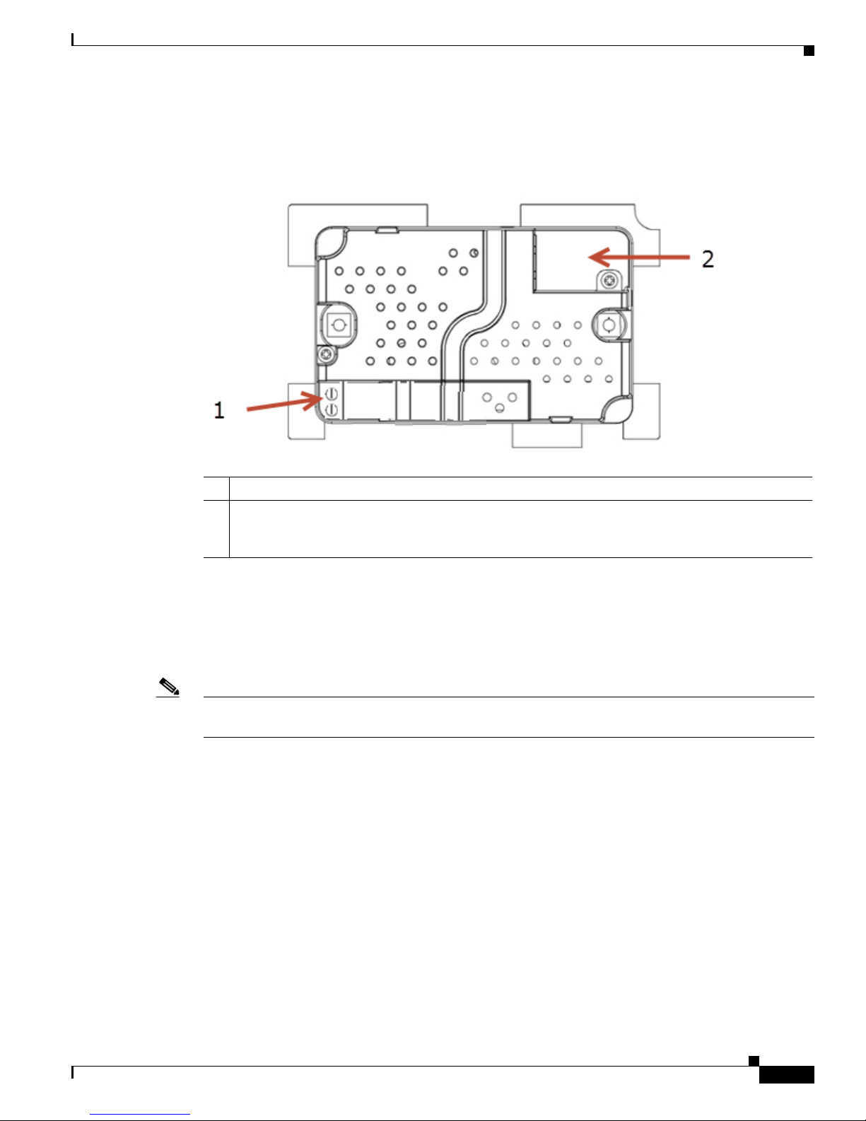
Back View
Touchscreen Placement
Figure 5 Back View with Camera and Power Box
1 Wire Connection. Hot (H) uses Black wire; Return (R) uses White wire.
2 RJ-45 port for Ethernet Connection. Ethernet port available for either a standard Ethernet source
that provides network communication only OR a PoE source that provides power to the device and
network communication.
Touchscreen Placement
Place the touchscreen in a convenient location at eye level, typically near the entrance of the room,
approximately 57 to 61 inches (145 cm to 155 cm) from the floor (see Figure 6).
Note Consider the camera on the panel and the height of the people in the residence who will use the camera
for video intercom.
OL-27263-01
Cisco Smart+Connected 7" In-wall Display Reference Guide
7
Page 8

LED Indicator
Figure 6 Touchscreen Placement
1 New Device
2 AC Power (unless using PoE)
LED Indicator
The LED on the touchscreen indicates the camera status of the camera and booting information as
described in the next table.
Table 2 LED Indicators
LED Color Touchscreen Status
Off Camera is Off
Green Camera is On
Green (blinks slow) Booting
Green (blinks rapidly) Restoring (during a factory restore)
Installation
Warning
WARNING! Before installing the touchscreen, switch off the circuit breaker or remove the fuse from
the fuse box.
AVERTISSEMENT! Pour l’endroit où vous installez l’écran tactile, coupez le disjoncteur ou enlevez le
fusible de la boîte de fusible.
Note IMPORTANT! Before you can complete the instructions below, you must have a Back Box installed
according to the documentation provided in the Back Box kit. See the “Back Box Options” section on
page 4 for details.
Cisco Smart+Connected 7" In-wall Display Reference Guide
8
OL-27263-01
Page 9

IMPORTANT! En coupant l’ouverture pour la boîte de mur, ne coupez pas l’ouverture trop grande.
Soyez conservateur et agrandissez-avec précaution la comme nécessaire.
Note IMPORTANT! When cutting the opening for the Back Box, DO NOT cut the opening too large. Be
conservative and cautiously enlarge it as needed.
IMPORTANT! En coupant l’ouverture pour la boîte de mur, ne coupez pas l’ouverture trop grande.
Soyez conservateur et agrandissez-avec précaution la comme nécessaire.
Power and Network Installation Options
This device uses an Ethernet or Wi-Fi network connection, and can be powered using PoE or AC power.
Choose one of the following options to install the power and network communication.
Caution Do not attempt to use PoE and AC power at the same time. Choose only one power option.
ATTENTION! Ne pas tenter d’utiliser PoE et AC en même temps. Choisir une seule option
d’alimentation.
Installation
Option 1: Ethernet Connection with a PoE Injector or a Third-Party Injector or Switch
PoE supplies DC power on the Ethernet cable using a a third-party PoE solution to provide the
touchscreen with power and a network connection. To set up your PoE and Ethernet connection with a
PoE Injector, see Figure 7.
Step 1 Attach the PoE Injector according to the instructions in your PoE’s installation guide if provided.
Step 2 Pull the Ethernet cable from that location to where you want to install the touchscreen.
OL-27263-01
Cisco Smart+Connected 7" In-wall Display Reference Guide
9
Page 10

Installation
Figure 7 Ethernet with PoE - Requires Ethernet Connection to PoE Injector
Option 2: Ethernet Connection with AC
The Ethernet is connected directly to the switch (see Figure 8). This power connection requires both
neutral and hot connections.
Figure 8 Ethernet - Requires a Connection to Ethernet and AC Power
Cisco Smart+Connected 7" In-wall Display Reference Guide
10
OL-27263-01
Page 11

Option 3: Wi-Fi Connection with AC
Place the touchscreen above a power source, for example, an outlet. Ensure that you have Wi-Fi in the
residence (see Figure 9).
Note • Video intercom. Although this device supports b/g/n, 802.11 b is not supported for video intercom
use.
• Wireless-N is recommended for video intercom.
Wireless Network Limitations
Many Wi-Fi Access Points handle Multicasts (Wi-Fi simultaneously sent to multiple devices, for
example, when the touchscreen broadcasts video to all stations) by slowing down transmission speed to
the 1 Mb basic rate. This can cause overall Wi-Fi congestion in the Wi-Fi network during the broadcast.
Video intercom response times and images may degrade at each device.
If a residence requires a large number of Wi-Fi devices, ensure that you have a robust Wi-Fi network
(possibly consisting of multiple access points).
Installation
Figure 9 Wi-Fi - Requires AC Power and WAP
OL-27263-01
Cisco Smart+Connected 7" In-wall Display Reference Guide
11
Page 12

Power Installation
Power Installation
Prepare the plastic power box for installation into the Back Box by inserting either the Ethernet cable or
the AC power cable into the power box (see Figure 10 and Figure 11), and then follow the instructions
next.
AC Power Connection
The steps below represent a typical U.S. installation.
Step 1 Connect the wires to the AC power source for the touchscreen according to the national and local
electrical codes. Installation may require alternative wires and the use of a terminal block.
Step 2 Thread the power cable through the bottom back hole of the Back Box to the terminal block (see
Figure 10).
Step 3 Strip the black and white po wer wire ends to 1/ 4” as neces sary. Using a flathead screwdriver, loosen the
screws on the power box’ s terminal block an d connect the power wires to each terminal (see Figure 10).
Step 4 Cap the ground wire from the wall if you are using a plastic Back Box. Attach the ground wire to the
Back Box if using a metal Back Box.
Figure 10 AC Power Connection
1 Power Box
2 Ter m i n a l Block
3 Connect Wires to Terminal Block
4 Back Box
5 Power Cable
Cisco Smart+Connected 7" In-wall Display Reference Guide
12
OL-27263-01
Page 13

Step 5 Align and bend the wires carefully to fit them inside the Back Box.
Step 6 Align and carefully slide the power box into the Back Box.
Step 7 Secure the power box into the B ack Box usin g the screws pr ovided.
Note NOTE: Overtightening the power box screws could result in a poor connection between the
touchscreen and the power box and could also cause the touchscreen to warp.
Step 8 Align and slide the back of the touchscreen into the power box. The touchscreen is magnetic and should
snap into place easily.
Step 9 (Optional) To secure the touchscreen inside the power box, remove the tape covering the bottom security
pin (see Figure 12) before attaching the touchscreen to the power box.
Power Over Ethernet (PoE) Connection
Connect the PoE Injector to power and the network, and then connect it to the power box.
The steps below describe how to install a PoE Injector.
Power Installation
Step 1 Connect the PoE Injector to an AC outlet using the power cord.
Step 2 Connect one of the RJ-45 LAN ports on the gateway/router/switch to the PoE Injector’s LAN port using
the RJ-45 Ethernet cable.
Step 3 Connect the PoE Injector’s PWR LAN-OUT port to the RJ-45 Ethernet cable that will be connected to
the touchscreen.
Step 4 Pull the Ethernet cable through the top back hole of the Back Box to the Ethernet connector on the top
back of the power box, and then connect it (see Figure 11).
Step 5 Align and carefully slide the power box into the Back Box until the touchscreen is attached to the power
box.
OL-27263-01
Cisco Smart+Connected 7" In-wall Display Reference Guide
13
Page 14

Power Installation
Figure 11 Ethernet Connection
1 Ethernet Connection
2 Power Box
3 Back Box
Step 6 Secure the power box into the Back Box using the screws provided.
Note Overtightening the power box screws could result in a poor connection between the
touchscreen and the power box and could also cause the touchscreen to warp.
Step 7 Align and slide the back of the touchscreen into the power box. The touchscreen is magnetic and should
snap into place easily.
Step 8 (Optional) To secure the touchscreen inside the power box, remove the tape covering the bottom security
pin before attaching the touchscreen to the power box.
Cisco Smart+Connected 7" In-wall Display Reference Guide
14
OL-27263-01
Page 15

Configuration
If the touchscreen will connect to the wireless network, you must configure the Wi-Fi settings on the
device. Use Composer Pro to add the touchscreen driver to your project and configure the device
features.
Refer to the following for more information:
• Configure for Wireless, page 15
• Configure in Composer Pro, page 16
Configure for Wireless
(Wi-Fi only) Complete the following procedure to connect to a WAP using the touchscreen.
Procedure
Step 1 After initialization, press and hold the large White 4 in the center of the touchscreen to enter the
configuration screen.
Step 2 Press the Network button on the touchscreen’s configuration page. The network configuration screen
displays.
Configuration
Step 3 Under Wireless, select Enable. If you don’t see the network you want, select Other.
Step 4 At Network Name, select to add the SSID or wireless network when the keyboard appears. Select Done.
Step 5 At Security, select None, WEP 64, WEP 128, WPA, or WPA2.
Step 6 At Password, type the password on the keyboard that appears. Press Done.
Step 7 Select Connect. Notice that the IP settings change. The IP address is set to DHCP by default.
Step 8 (Optional) If you need to set a static IP address instead, complete the following steps:
a. On the Network page, press Static.
b. Select each box one at a time and type the address: IP Address, Subnet Mask, Default Gateway,
Preferred DNS, and Alternate DNS.
c. When the keyboard appears, type the address, and then press Done.
Step 9 Press OK to return to the Network page. You can now connect to a Director (Cisco Controller) on the
network.
Step 10 Press OK.
OL-27263-01
Cisco Smart+Connected 7" In-wall Display Reference Guide
15
Page 16

Troubleshooting
Configure in Composer Pro
When the touchscreen is physically installed and appears on the residential network, you can add and
configure it for the System using Composer Pro. Choose the In-Wall 7” Touch Screen V2 driver in
Composer Pro and add it to your project.
See the Cisco Smart+Connected Residential Installation and Configuration Guide for more information.
Troubleshooting
Boot Up
When the device is booting up, it may take 30 seconds or longer before the Green LED turns on. When
it turns on, it blinks slowly for a time and then turns off. After that, you will see an image on the
touchscreen.
Restore to Factory Default
If the camera’s LED blinks on and off for more than 30 seconds, the device will need to be restored.
To access the Factory Restore switch, you’ll first need to remove the touchscreen.
Note If there’s tape on the bottom of the power box, simply lift the touchscreen off. Remove the tape to lock
the touchscreen in place. If there’s no tape, the touchscreen is locked into place. In this case, follow the
instructions below.
Step 1 Locate the small hole underneath the touchscreen’s faceplate (see Figure 12 through Figure 15).
Figure 12 Touchscreen Underside - Pin and Pinhole
1 Speaker
2 Insert paper clip here to remove touchscreen
3 Security pin
Cisco Smart+Connected 7" In-wall Display Reference Guide
16
OL-27263-01
Page 17

Restore to Factory Default
Step 2 Using a small unbent paper clip, insert the paper clip straight up and into the small hole (about 1/4”) or
as far as you can. There’s another small hole inside the touchscreen which the paper clip needs to insert
into also (see Figure 13 through Figure 15). You may need to wiggle the paper clip a bit to get it into the
second small hole.
Figure 13 Locate the Touchscreen Hole
1 Insert the paper clip through this slot
2 Continue to insert the paper clip through the small hole
3 Bottom of the touchscreen
OL-27263-01
Cisco Smart+Connected 7" In-wall Display Reference Guide
17
Page 18

Restore to Factory Default
Figure 14 Insert the Paper Clip Though the Small Hole
Figure 15 Paper Clip Needs to Engage Release Plate
Cisco Smart+Connected 7" In-wall Display Reference Guide
18
OL-27263-01
Page 19

Restore to Factory Default
Step 3 With both hands, tilt the bottom of the touchscreen out and gently remove the touchscreen.
Step 4 On the back of the touchscreen locate the small switch (see Figure 16).
Figure 16 Factory Restore Switch
Step 5
Using the tip of a straight pin or paper clip, change the position of the switch, for example, if the switch
is in the down position, push it to the up position. The touchscreen will then sense the change on the next
power up, and will initiate the restore process.
Step 6 When you are finished with the restore, reattach the touchscreen into the power box in the wall— top
first—and then snap the bottom of the touchscreen back into place.
Step 7 The touchscreen will reboot and the factory default firmware image will be installed. All settings will
reset to the factory default settings. See the “LED Indicator” section on page 8 for information about
how the LED behaves during a factory restore.
Step 8 After a restore, the touchscreen will need to be updated to the same image version of the project (e.g.,
OS 2.2.2 or later).
OL-27263-01
Cisco Smart+Connected 7" In-wall Display Reference Guide
19
Page 20

Specifications
Specifications
Table 3 Cisco In-wall Display Specifications
Basic Specifications Description
Display
Integrated camera 640 x 480 VGA, 30 fps
Display dimensions 7-inch TFT LCD
Pixel resolution 800 x 480
Touchscreen Capacitive touch
Programmable buttons 4
Intercom
Microphone Dual microphones
Min. lumination: 5 Lux
Viewing angle: 60 degrees
Voice pick up from 10 feet away, Beamforming
Speaker Internal
Video and audio Full-duplex video (H.264) and
audio (G.722)
Communications
Wi-Fi Wireless-N (2.4-GHz 802.11n/g/b)
RF frequency: 2.4 GHz
Antenna: Internal
Encryption: 64/128 Wired Equivalent Privacy (WEP), Temporal Key
Integrity Protocol (TKIP)/Advanced Encryption Standard (AES)
Authentication: Wi-Fi Protected Setup (WPS), WEP, Wi-Fi Protected
Access (WPA), WPA2
Ethernet 10/100 Base-T Ethernet RJ-45
Power
Power supply PoE (IEEE 802.3af)
AC 100V to 240V, 50 to 60 Hz
Power over Ethernet Yes
Other
Audio G.722 Wideband Audio
Environmental
Cisco Smart+Connected 7" In-wall Display Reference Guide
20
OL-27263-01
Page 21

Regulatory/Safety Information
Table 3 Cisco In-wall Display Specifications (continued)
Operating temperature 32°F to 104°F (0°C to 40°C)
Relative humidity: 95%
Storage temperature –4°F to 149°F
(–20°C to 65°C)
Buttons and Outputs
Reset Reset: Run a magnet from left to right along bottom of panel
Restore Factory Defaults: Remove panel from wall, toggle the
two-position switch behind the panel, remount panel on the wall. This
will reset the display to default settings and may require the device to
be updated in the project.
Dimensions
W x H x D 4 7/8” x 1 1/8” x 7 1/4”
(124mm x 29mm x 184mm)
Mounting In-wall
Regulatory/Safety Information
To review regulatory information, go to www.cisco.com/go/smartconnectedresidential/docs.
Related Documentation
For more information about the Cisco Smart+Connected Residential products, see the following
documents and websites:
Subject / Document Title Location
General
Product Information and Home Page www.cisco.com/go/smartconnectedresidential
Cisco 1-Year Limited Hardware Warranty Terms www.cisco.com/go/smartconnectedresidential
warranty
Regulatory Compliance and Safety Information for Cisco Smart+Connected
Residential Products
Cisco Support www.cisco.com/cisco/web/support/
Technical Documentaion
www.cisco.com/go/smartconnectedresidential/
docs
OL-27263-01
Cisco Smart+Connected 7" In-wall Display Reference Guide
21
Page 22

Warranty
Installation and Configuration
Cisco Smart+Connected Residential Installation and Configuration Guide
Cisco RMS Installation and Administration
Cisco Smart+Connected Remote Management Console Administration
Guide
Cisco Smart+Connected Remote Management Server Installation Guide
Reference Guides
Cisco Smart+Connected Controller 200 Reference Guide
Cisco Smart+Connected Controller 250 Reference Guide
Cisco Smart+Connected Controller 800 Reference Guide
Cisco Smart+Connected 7” In-wall Display Reference Guide
Cisco Smart+Connected Portable Tablet Reference Guide
Cisco Smart+Connected I/O Extender Reference Guide
Cisco Smart+Connected Universal Remote 150 Reference Guide
Cisco Smart+Connected Universal Remote 250 Reference Guide
Cisco Smart+Connected Video Door Station Reference Guide
Cisco Smart+Connected Residential Licensing Guide See your Cisco representative or partner for
Smart Device Compatibility and other information:
Cisco Smart+Connected Smart Device License for Real Estate Developers
Composer Pro User Guide http://www.control4.com/documentation/Com
www.cisco.com/go/smartconnectedresidential/
docs
more information.
www.cisco.com/go/smartconnectedresidential
poser_Pro_User_Guide/index.htm
Warranty
A Cisco 1-year warranty applies. Go to the following URL for more information:
www.cisco.com/go/smartconnectedresidentialwarranty
Service and Support
Cisco offers a wide range of support programs to accelerate customer success. These innovative
programs are delivered through a unique combination of people, processes, tools, and partners, resulting
in high levels of customer satisfaction. For more information, contact your Cisco sales representative or
go to www.cisco.com/cisco/web/support/index.html
Cisco Smart+Connected 7" In-wall Display Reference Guide
22
OL-27263-01
Page 23

Service and Support
This document is to be used in conjunction with the documents listed in the “Related Documentation” section.
Cisco and the Cisco logo are trademarks or registered trademarks of Cisco and/or its affiliates in the U.S. and other countries. To view a list of
Cisco trademarks, go to this URL: www.cisco.com/go/trademarks. Third-party trademarks mentioned are the property of their respective owners. The
use of the word partner does not imply a partnership relationship between Cisco and any other company. (1110R)
Any Internet Protocol (IP) addresses and phone numbers used in this document are not intended to be actual addresses and phone numbers. Any
examples, command display output, network topology diagrams, and other figures included in the document are shown for illustrative purposes only.
Any use of actual IP addresses or phone numbers in illustrative content is unintentional and coincidental.
© 2012 Cisco Systems, Inc. All rights reserved.
OL-27263-01
Cisco Smart+Connected 7" In-wall Display Reference Guide
23
Page 24

Service and Support
Cisco Smart+Connected 7" In-wall Display Reference Guide
24
OL-27263-01
 Loading...