

Page 1

RV160x Administration Guide
First Published: 2018-03-07
Last Modified: 2019-12-13
Americas Headquarters
Cisco Systems, Inc.
170 West Tasman Drive
San Jose, CA 95134-1706
USA
http://www.cisco.com
Tel: 408 526-4000
800 553-NETS (6387)
Fax: 408 527-0883
Page 2

THE SPECIFICATIONS AND INFORMATION REGARDING THE PRODUCTS IN THIS MANUAL ARE SUBJECT TO CHANGE WITHOUT NOTICE. ALL STATEMENTS,
INFORMATION, AND RECOMMENDATIONS IN THIS MANUAL ARE BELIEVED TO BE ACCURATE BUT ARE PRESENTED WITHOUT WARRANTY OF ANY KIND,
EXPRESS OR IMPLIED. USERS MUST TAKE FULL RESPONSIBILITY FOR THEIR APPLICATION OF ANY PRODUCTS.
THE SOFTWARE LICENSE AND LIMITED WARRANTY FOR THE ACCOMPANYING PRODUCT ARE SET FORTH IN THE INFORMATION PACKET THAT SHIPPED WITH
THE PRODUCT AND ARE INCORPORATED HEREIN BY THIS REFERENCE. IF YOU ARE UNABLE TO LOCATE THE SOFTWARE LICENSE OR LIMITED WARRANTY,
CONTACT YOUR CISCO REPRESENTATIVE FOR A COPY.
The following information is for FCC compliance of Class A devices: This equipment has been tested and found to comply with the limits for a Class A digital device, pursuant to part 15
of the FCC rules. These limits are designed to provide reasonable protection against harmful interference when the equipment is operated in a commercial environment. This equipment
generates, uses, and can radiate radio-frequency energy and, if not installed and used in accordance with the instruction manual, may cause harmful interference to radio communications.
Operation of this equipment in a residential area is likely to cause harmful interference, in which case users will be required to correct the interference at their own expense.
The following information is for FCC compliance of Class B devices: This equipment has been tested and found to comply with the limits for a Class B digital device, pursuant to part 15 of
the FCC rules. These limits are designed to provide reasonable protection against harmful interference in a residential installation. This equipment generates, uses and can radiate radio
frequency energy and, if not installed and used in accordance with the instructions, may cause harmful interference to radio communications. However, there is no guarantee that interference
will not occur in a particular installation. If the equipment causes interference to radio or television reception, which can be determined by turning the equipment off and on, users are
encouraged to try to correct the interference by using one or more of the following measures:
• Reorient or relocate the receiving antenna.
• Increase the separation between the equipment and receiver.
• Connect the equipment into an outlet on a circuit different from that to which the receiver is connected.
• Consult the dealer or an experienced radio/TV technician for help.
Modifications to this product not authorized by Cisco could void the FCC approval and negate your authority to operate the product
The Cisco implementation of TCP header compression is an adaptation of a program developed by the University of California, Berkeley (UCB) as part of UCB’s public domain version of
the UNIX operating system. All rights reserved. Copyright©1981, Regents of the University of California.
NOTWITHSTANDING ANY OTHER WARRANTY HEREIN, ALL DOCUMENT FILES AND SOFTWARE OF THESE SUPPLIERS ARE PROVIDED "AS IS" WITH ALL FAULTS.
CISCO AND THE ABOVE-NAMED SUPPLIERS DISCLAIM ALL WARRANTIES, EXPRESSED OR IMPLIED, INCLUDING, WITHOUT LIMITATION, THOSE OF
MERCHANTABILITY, FITNESS FOR A PARTICULAR PURPOSE AND NONINFRINGEMENT OR ARISING FROM A COURSE OF DEALING, USAGE, OR TRADE PRACTICE.
IN NO EVENT SHALL CISCO OR ITS SUPPLIERS BE LIABLE FOR ANY INDIRECT, SPECIAL, CONSEQUENTIAL, OR INCIDENTAL DAMAGES, INCLUDING, WITHOUT
LIMITATION, LOST PROFITS OR LOSS OR DAMAGE TO DATA ARISING OUT OF THE USE OR INABILITY TO USE THIS MANUAL, EVEN IF CISCO OR ITS SUPPLIERS
HAVE BEEN ADVISED OF THE POSSIBILITY OF SUCH DAMAGES.
Any Internet Protocol (IP) addresses and phone numbers used in this document are not intended to be actual addresses and phone numbers. Any examples, command display output, network
topology diagrams, and other figures included in the document are shown for illustrative purposes only. Any use of actual IP addresses or phone numbers in illustrative content is unintentional
and coincidental.
Cisco and the Cisco logo are trademarks or registered trademarks of Cisco and/or its affiliates in the U.S. and other countries. To view a list of Cisco trademarks, go to this URL: www.cisco.com
go trademarks. Third-party trademarks mentioned are the property of their respective owners. The use of the word partner does not imply a partnership relationship between Cisco and any
other company. (1721R)
©
2018 Cisco Systems, Inc. All rights reserved.
Page 3

CONTENTS
CHAPTER 1
CHAPTER 2
Getting Started 1
RV160X Product Features 1
Getting Started 5
Launch Setup Wizard 6
User Interface 7
Status and Statistics 11
System Summary 11
TCP/IP Services 13
Port Traffic 14
WAN QoS Statistics 15
Switch QoS Statistics 16
Connected Devices 16
Routing Table 17
DHCP Bindings 17
VPN Status 18
CHAPTER 3
View Logs 19
Captive Portal Status 20
Administration 21
File Management 21
Manual Upgrade 22
Auto Update 22
Firmware Auto Fallback Mechanism 23
Reboot 23
Diagnostic 24
RV160x Administration Guide
iii
Page 4

Contents
Certificate 24
Import Certificate 24
Generate CSR/Certificate 25
Show Built-in 3rd Party CA Certificates 26
Configuration Management 26
Copy/Save Configuration 26
CHAPTER 4
System Configuration 27
Initial Router Setup 27
System 29
Time 29
Log 30
Email Server 31
Remote Syslog Servers 31
Email 32
User Accounts 32
Remote Authentication Service 34
User Groups 34
IP Address Groups 36
SNMP 36
Discovery-Bonjour 37
LLDP 37
Automatic Updates 38
CHAPTER 5
iv
Schedules 39
Service Management 39
PnP (Plug and Play) 39
Plug and Play Connect Service 40
Creating a Controller Profile 40
Registering Devices 41
WAN 43
WAN Settings 43
Dynamic DNS 46
IPv6 Transition 46
RV160x Administration Guide
Page 5

IPv6 in IPv4 Tunnel (6in4) 46
IPv6 Rapid Deployment (6rd) 47
Contents
CHAPTER 6
CHAPTER 7
LAN 49
Port Settings 49
VLAN Settings 50
Option82 Settings 52
Static DHCP 53
802.1X Configuration 53
Router Advertisement 54
Wireless 57
Basic Settings 57
Concurrent Dual Band Selection 59
Configuring 2.4 GHz Radio 59
Configuring 5 GHz Radio 60
Advanced Settings 61
WPS 62
Captive Portal 63
CHAPTER 8
CHAPTER 9
Lobby Ambassador 64
Routing 67
Static Routing 67
RIP 68
IGMP Proxy 69
Firewall 71
Basic Settings 71
Access Rules 73
Network Address Translation 74
Static NAT 74
Port Forwarding 75
Port Triggering 76
Policy NAT 77
RV160x Administration Guide
v
Page 6

Contents
Policy NAT Use Cases 77
Session Timeout 80
DMZ Host 81
CHAPTER 10
CHAPTER 11
VPN 83
VPN Setup Wizard 83
IPSec VPN 85
IPSec Profiles 86
Site-to-Site 88
Site-to-Site VPN Connection 88
Client to Site 91
OpenVPN 93
PPTP Server 94
GRE Tunnel 95
VPN Passthrough 95
Resource Allocation 96
Security 97
Content Filtering 97
CHAPTER 12
CHAPTER 13
QoS 99
Traffic Classes 99
WAN Queuing 100
WAN Policing 101
WAN Bandwidth Management 102
Switch Classification 102
Switch Queuing 103
Where To Go 105
Where To Go From Here 105
RV160x Administration Guide
vi
Page 7

Getting Started
This section describes how to get started on the device and contains the following topics:
• RV160X Product Features, on page 1
• Getting Started, on page 5
• Launch Setup Wizard, on page 6
• User Interface, on page 7
RV160X Product Features
Thank you for purchasing the Cisco RV160/RV160W VPN routers. The Cisco RV160 and RV160W VPN
routers are high-performance models that combine business-class features with security, reliability and overall
value. Both models are perfect for the small business or small home office network.
• Features and Benefits
• RV160 VPN Router provides wired connectivity
• RV160W is a wireless VPN Router: 2x2 11ac wireless
CHAPTER 1
• Flexible SFP/RJ45 combination WAN Ports
• Native 4-port Switch
• High-performance Gigabit Ethernet ports, enabling large file transfers and multiple users
• IP Security, PPTP and Open VPN Server for secure connectivity for remote employees and multiple
office sites
• Strong security: Proven stateful packet inspection (SPI) firewall and hardware encryption
• Easy to set up and use with wizard-based configuration
• New User Interface design for easier configuration and device management
• Updated, new hardware enclosure design
Product Specifications
SpecificationDescription
RJ45 SFP Gigabit Combination PortEthernet WAN
RV160x Administration Guide
1
Page 8

RV160X Product Features
Getting Started
SpecificationDescription
4 RJ45 Gigabit EthernetEthernet LAN
1 RJ45Console Port
Power On/OffSwitch
CAT5 or betterCabling Type
Power, VPN, WAN, LANLED’s
LinuxOperating System
LAN
16VLAN
Yes, 802.1XPort Security
Dual Stack, 6rd,6in4IPv6
WAN
Security
Network
Dynamic Host Configuration Protocol (DHCP) client,
static IP, Point-to-Point Protocol over Ethernet
(PPPoE), PPTP, L2TP, transparent bridge
2x2 Wireless 11acWLAN
Stateful Packet Inspection (SPI) FirewallFirewall
Port-Forwarding and Triggering
Denial of Service prevention (DoS)
IP access control listsAccess Control
HTTPS, username/password complexitySecure Management
Two levels of access: Admin and GuestUser Privileges
RV160x Administration Guide
2
Page 9

Getting Started
RV160X Product Features
SpecificationDescription
Network Protocols
• Dynamic Host Configuration Protocol (DHCP)
server
• Point-to-Point Protocol over Ethernet (PPPoE)
• Point-to-Point Tunneling Protocol (PPTP)
• Layer 2 Tunneling Protocol (L2TP)
• DNS proxy
• DHCP relay agent
• IGMP Proxy and multicast forwarding
• Rapid Spanning Tree Protocol (RSTP)
• Dynamic Domain Name System (TZO, DynDNS,
3322.org, NOIP)
• Network Address Translation (NAT), Port
Address Translation (PAT)
• One-to-One NAT
• Port management
• Port mirroring
• Software configurable DMZ to any LAN IP
address
Routing Protocols
Network Address Translation (NAT Protocol
VPN
• Session Initiation Protocol (SIP) Application
Layer Gateways (ALG)
• Static routing, IGMP proxy
• Dynamic routing
• RIP v1 and v2
• RIP for IPv6 (RIPng)
• Inter-VLAN routing
Port Address Translation (PAT), Network Address
Port Translation (NAPT)
Port forwarding, One-to-one NAT, VPN NAT
Transversal, Session Initiation (SIP), Application
Level Gateway (ALG), FTP ALG
10 IPsec TunnelsGateway-to-Gateway IPsec VPN
10 IPsec TunnelsClient-to-Gateway IPsec VPN
RV160x Administration Guide
3
Page 10

RV160X Product Features
Getting Started
SpecificationDescription
IKEv2, GRE, Hub and Spoke supportedIPsec VPN
10 PPTP VPN TunnelsPPTP VPN
Support for the Open VPN ServerOpen VPN
Encryption
VPN Pass-Through
Quality of Service
QoS
Jumbo Frame Support
Performance
3DES, AES with 128, 192 and 256 bit keys
Encryption
IPsec/PPTP/Layer 2 Tunneling Protocol (L2TP)
pass-through
• 802.1p port-based priority on LAN port,
application-based priority on WAN port
• 3 queues
• Differentiated Services Code Point support
(DSCP)
• Class of Service (CoS)
• Bandwidth Management for service prioritization
Supports Jumbo Frame on Gigabit ports-at least
1536B
600 MbpsNAT Throughput
15,000Concurrent Sessions
Configuration
Management
Upgradeability
Environmental
Power
50 MbpsIPsec VPN Throughput
Browser-based configuration (HTTP/HTTPS)Web-based User Interface
Web-based User Interface, SNMP v3, Bonjour,
Universal Plugand Play (UPnP)
FindIT Support for Monitoring and Management
Local, Syslog, email alertsEvent Logging
Ping, Traceroute, DNS LookupNetwork Diagnostics
Firmware upgradeable via browser UI,
imported/exported file, USB, Cisco FindIT
NTP, Daylight Savings, Manual EntrySystem Time
RV160: 12VDC/1.5A
RV160W: 12VDC/2A
RV160x Administration Guide
4
Page 11

Getting Started
Getting Started
SpecificationDescription
0° to 40°C (32° to 104°F)Operating Temperature
-20° to 70°C (-4° to 158°F)Storage Temperature
10% to 85% noncondensingOperating Humidity
5% to 90% noncondensingStorage Humidity
Certifications
Safety:
• UL 60950-1
• CAN/CSA-C22.2 No. 60950-1
• IEC 60950-1
• EN 60950-1
Radio approvals:
• FCC Part 15.247, 15.407
• RSS-210 (Canada)
• EN 300.328, EN 301.893 (Europe)
• AS/NZS 4268.2003 (Australia and New Zealand)
EMI and susceptibility (Class B):
• FCC Part 15.107 and 15.109
• ICES-003 (Canada)
• EN 301.489-1 and -17 (Europe)
Getting Started
Your device comes with default settings that are optimized for many small businesses. However, your network
demands or Internet Service Provider (ISP) might require you to modify a few of these settings. You can do
so using the web interface, that is using Internet Explorer, Firefox or Safari (for Mac) on a PC.
To launch the web interface, follow these steps:
Step 1 Connect a PC to a numbered LAN port on the device. If the PC is configured to become a Dynamic Host Configuration
Protocol (DHCP) client, an IP address in the 192.168.1.x range is assigned to the PC. DHCP automates the process of
assigning IP addresses, subnet masks, default gateways and other settings to computers. Computers must be set to
participate in the DHCP process to obtain an address. This is done by selecting to obtain an IP address automatically in
the properties of TCP/IP on the computer.
Step 2 Start a web browser.
Step 3 In the address bar, enter the default IP address of the device, 192.168.1.1. The browser might issue a warning that the
website is untrusted. Continue to the website.
RV160x Administration Guide
5
Page 12

Getting Started
Launch Setup Wizard
Step 4 When the sign-in page appears, enter the default username cisco and the default password cisco (lowercase).
Step 5 Click Login. The Getting Started page appears. You can use the various links available on this page and follow the
on-screen instructions to quickly configure your network device.
Note
Also, you can use a wireless PC to configure the RV160W and RV260W router models. When the router boots up from
the factory default settings, a temporary SSID is enabled. You can connect to this SSID to configure the router.
Step 6 On a PC, search the Service Set Identifier (SSID) and configure as listed below. Then, the wireless connection is up and
the PC obtains the address in the range 192.168.1.x.
If you have trouble connecting to the Internet or the web-based interface:
• Verify that your web browser is not set to Work Offline.
• Check the local area network connection settings for your Ethernet adapter. The PC should obtain an IP
address through DHCP. Alternatively, the PC can have a static IP address in the 192.168.1.x range with
the default gateway set to 192.168.1.1 (the default IP address of the device).
• Verify that you entered the correct settings in the Wizard to set up your Internet connection.
• Reset the modem and the device by powering off both devices. Next, power on the modem and let it sit
idle for about 2 minutes. Then power on the device. You should now receive a WAN IP address.
• If you have a DSL modem, ask your ISP to put the DSL modem into bridge mode.
• CiscoSB-Setup
• Security: WPA2-PSK
• Pre-shared Key: cisco123
• Channel: Auto
Step 7 Access the Launch Setup Wizard page by completing steps 2 to 5. Once on the page, follow the instructions that appear
online. After submitting the configuration in the setup wizard, the temporary service set identifier (SSID) will be deleted
and the new configuration will be applied.
Note
The temporary SSID (CiscoSB-Setup) is only used for the initial setup wizard. It should not be used to forward
traffic. To find your SSID, open your computer's Wi-Fi settings and look at the available Wi-Fi networks within
your range.
Launch Setup Wizard
From the Launch Setup Wizard page, follow the instructions that guide you through the process for configuring
the device.
To open this page, select Launch Setup Wizard in the navigation pane and follow the on-screen instructions
to proceed. Refer to your ISP for the information required to setup your Internet connection.
Launch Setup Wizard
Link to the Initial Router Setup.Initial Router Setup
RV160x Administration Guide
6
Page 13
Getting Started
User Interface
Link to the VPN Status Wizard.VPN Setup Wizard
Initial Configuration
Change Administrator
Password
Quick Access
Firmware
Configure Remote
Management Access
Backup Device
Configuration
Device Status
System Summary
VPN Status
Port Statistics
Link to the User Accounts page where you can change the administrator
password and set up a guest account.
Link to the WAN Settings page where you can modify the WAN parameters.Configure WAN Settings
Link to the VLAN Membership page where you can configure the VLAN.Configure LAN Settings
Link to the File Management page where you can update the device firmware.Upgrade Router
Link to the Firewall >Basic Settings page where you can enable the basic
features of the device.
Link to the Config Management page where you can manage the router’s
configuration.
Link to the System Summary page that displays the IPv4 and IPv6 configuration,
and firewall status on the device.
Link to the VPN Status page that displays the status of the VPNs managed by
this device.
Link to the Port Traffic page which displays the device’s port status and port
traffic.
Traffic Statistics
User Interface
The user interface is designed to make it easy to set up and manage the device.
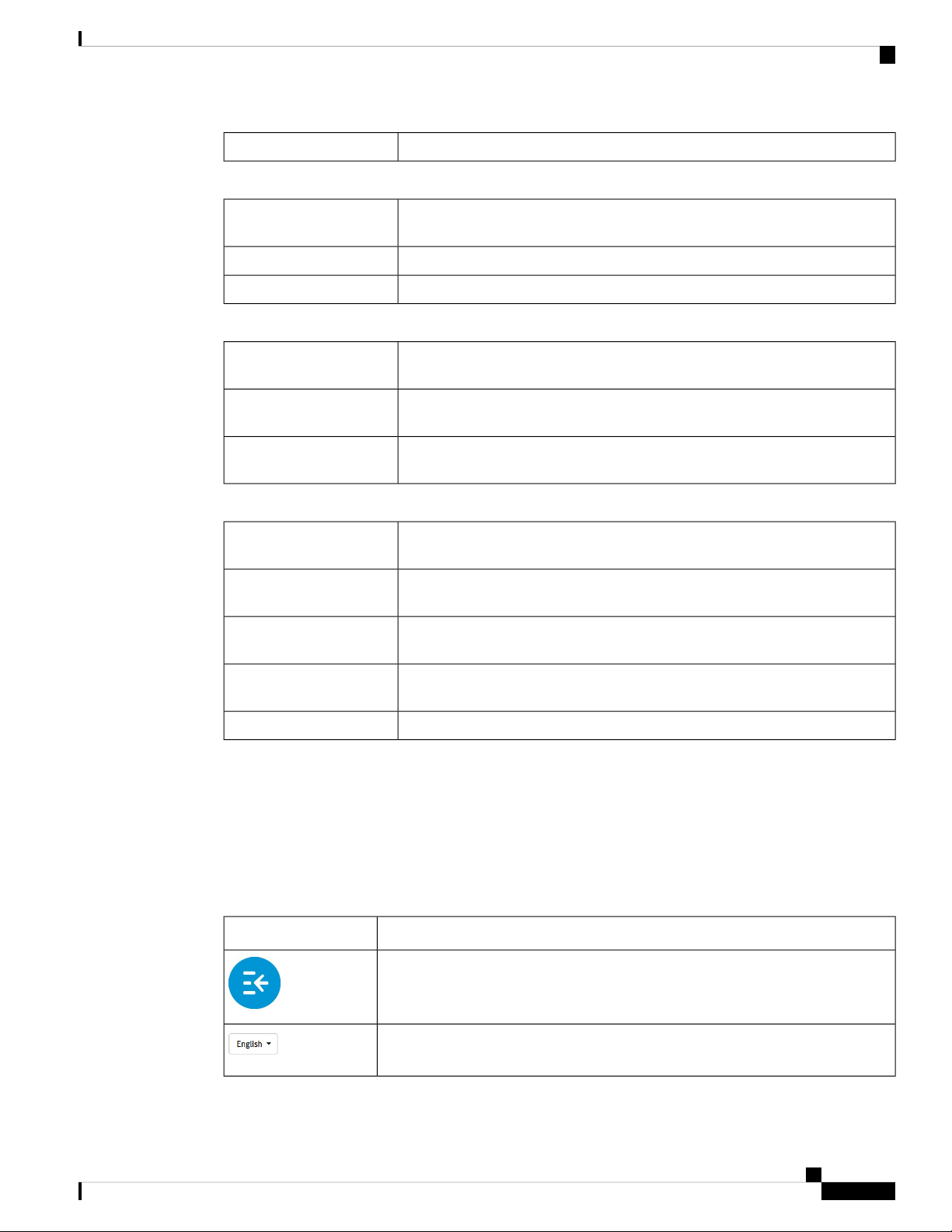
The header toolbar icons are described in the table below.
Table 1: Header Toolbar Options
Link to the TCP/IP Services page which displays the device’s port listen status
and the established connection status.
Link to the View Logs page which displays the logs on the device.View System Log
DescriptionIcon
Toggle button – Located on the top left of the header – This toggle button helps
to expand or collapse the navigation pane.
Language Selection – This drop-down list allows you to select the language for
the user interface.
RV160x Administration Guide
7
Page 14
User Interface
Getting Started
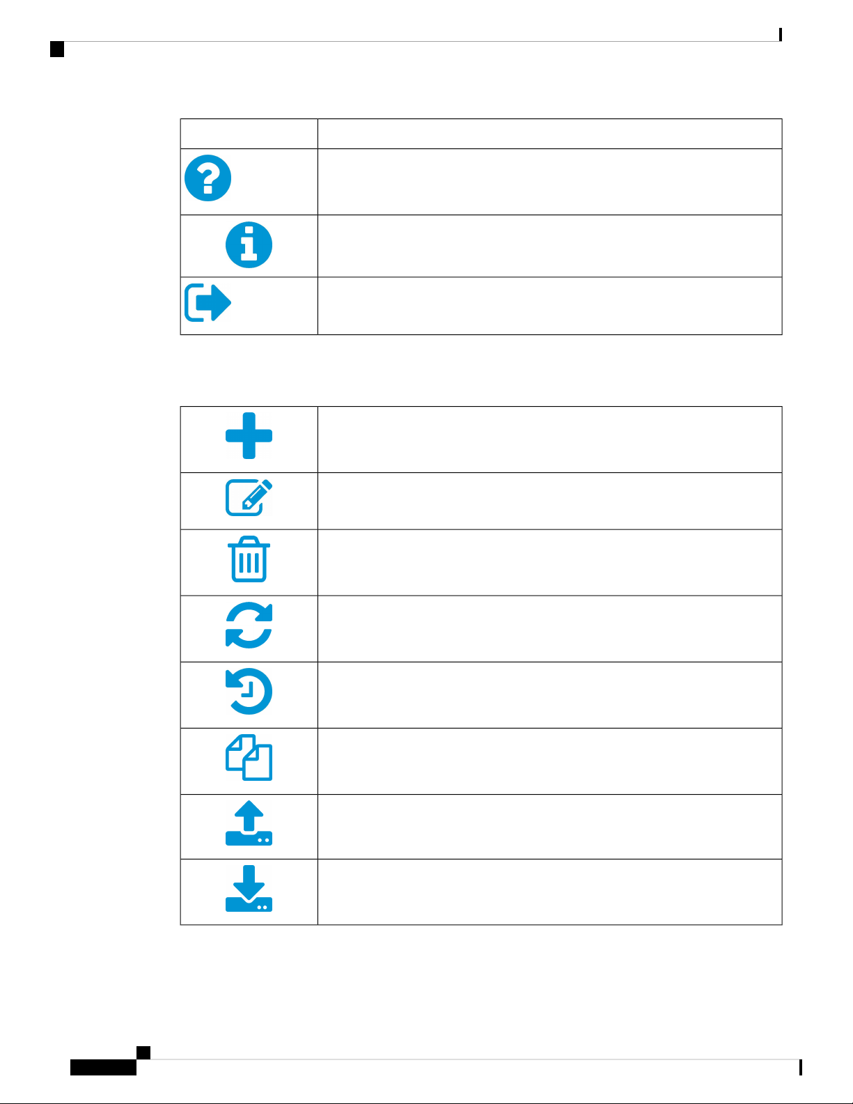
DescriptionIcon
Help – The online-help documentation for the router.
About – The firmware version information for the router.
Logout – Click to log out of the router.
Icon Legend
This table displays the most common icons found throughout the router's graphical interface and their meanings.
Add – Click to add an entry.
Edit – Click to edit an entry.
Delete – Click to delete an entry.
Refresh – Click to refresh the data.
Reset counters – Click to reset the counters.
Clone – Click to clone the settings.
Export – Click to export the configurations.
Import – Click to import the configurations.
RV160x Administration Guide
8
Page 15

Getting Started
User Interface
Popup Windows
Some links and buttons launch popup windows that display more information or related configuration pages.
If the web browser displays a warning message about the popup window, allow the blocked content.
RV160x Administration Guide
9
Page 16

User Interface
Getting Started
RV160x Administration Guide
10
Page 17

Status and Statistics
This section describes the device's status and statistics and contains the following topics:
• System Summary, on page 11
• TCP/IP Services, on page 13
• Port Traffic, on page 14
• WAN QoS Statistics, on page 15
• Switch QoS Statistics, on page 16
• Connected Devices, on page 16
• Routing Table, on page 17
• DHCP Bindings, on page 17
• VPN Status, on page 18
• View Logs, on page 19
• Captive Portal Status, on page 20
System Summary
CHAPTER 2
The System Summary provides a snapshot of the settings on your device. It displays your device’s firmware,
serial number, port traffic, routing status, VPN server settings, and mobile networks. To view this System
Summary, click Status and Statistics> System Summary.
System Information
• Serial Number – The serial number of the device.
• System Up Time – The active length of time in yy-mm-dd, hours, and minutes that the device has been
up.
• Current Time – The current date and time.
• PID VID – The hardware version number.
• LAN MAC – The LAN MAC address.
• WAN MAC – The WAN MAC address.
RV160x Administration Guide
11
Page 18

System Summary
Status and Statistics
Firmware Information
• Firmware Version – The firmware version number installed on the router.
• Firmware MD5 Checksum – A value used for file validation.
• Locale – Defined localization support.
• Language Version – Language version.
• Language MD5 Checksum – A value used for language file validation.
Port Status
• Port ID – Defined name and number of the port.
• Interface – Name of the interface used for the connection.
• Status – Status of connection
• Speed – Connection speed.
IPv4 and IPv6
Internet Protocol version 4 (IPv4) and Internet Protocol version 6 (IPv6) are numerical IP addresses necessary
for Internet-enabled devices to communicate. Without IP addresses, computers would not be able to
communicate and send data to each other. It's essential to the infrastructure of the web.
This section diplays the following:
• IP Address – IP address assigned to the interface.
• Default Gateway – Default gateway for the interface.
• DNS – IP address of the DNS server. A DNS server is a computer server that contains a database of
public IP addresses and their associated hostnames.
• Dynamic DNS – Dynamic domain name system (DNS) is a method of automatically updating a name
server in the DNS, often in real time, with the active DDNS configuration of its configured hostnames,
addresses or other information. This displays the IP address of the DDNS for the interface and if it is
Disabled or Enabled.
• Disconnect – Click to disconnect the connection.
• Renew – Click to renew the IP address.
Note
• Connect or Disconnect buttons are applicable when the WAN connection type is PPTP, L2TP, and
PPPoE.
• WAN gets connected only if you reconnect or change the WAN configuration after disconnecting the
existing WAN connection.
RV160x Administration Guide
12
Page 19

Status and Statistics
TCP/IP Services
Wireless Status
This section displays the status of the Wireless.
• Radio 1 (2.4G), Radio 2 (5G), and Enabled – Bands displaying the MAC address, mode, channel, and
operation bandwidth and their details.
VPN Status
This section displays the status of the VPN tunnels.
• Type – Type of VPN tunnel.
• Active – If VPN is Enabled (active) or Disabled.
• Configured – VPN tunnel’s status whether it is configured or not.
• Max Supported – The maximum number of tunnels supported on the device.
• Connected – Status of the tunnel.
Firewall Setting Status
This section displays the status of the firewall.
• Stateful Packet Inspection (SPI) –Status of the SPI filter service is enabled (on) or disabled (off).
Legitimate packets are only allowed through the firewall. It is also called a dynamic packet filtering.
• Denial of Service (DoS) – Status of the DoS filter service is enabled (on) or disabled (off). A DoS attack
is an attempt to make a machine or network resource unavailable to its intended users.
• Block WAN Request – Makes it difficult for outside users to work their way into your network by hiding
the network ports from Internet devices and preventing the network from being pinged or detected by
other Internet users.
• Remote Management – Indicates that a remote connection for managing the device is allowed or denied.
• Access Rule – Number of access rules that have been set.
Log Setting Status
Logs allow you to track router activity, process failures, firewall events, connects and disconnects of WAN
devices, DDNS (Dynamic DNS) updates, VPN connection statuses, and many other events taking place in
your router. Logs are a very useful tool in troubleshooting and monitoring your router’s health at any given
time.
• Syslog Server – Status of system logs.
• Email Log – Status of logs to send using email.
TCP/IP Services
The TCP/IP Services page displays the statistics of the protocol, port, and IP address. To view the TCP/IP
Services, click Status and Statistics > TCP/IP Services.
RV160x Administration Guide
13
Page 20

Port Traffic
Status and Statistics
Port Listen Status
This section displays the status of which ports are open to receiving data (listening).
• Protocol – Type of protocol used for communication.
• Listen IP Address – The listening IP address displays the interface it is listening on.
• Listen Port – The listening port serves as an endpoint in an operating system for many types of
communication.
Established Connection Status
This section displays status on which ports have an established connection.
• Protocol – Type of protocol used for communication.
• Local IP Address – IP address of the system.
• Local Port – Listening ports on different services.
• Foreign Address – IP address of the device connected.
Port Traffic
• Foreign Port – Port of the device connected.
• Status – Connection status of the session.
The Port Traffic page displays the statistics and status of the interfaces of the device. To view the device’s
Port Traffic page, click Status and Statistics >Port Traffic.
Port Traffic
• Port ID – Port ID.
• Port Label – Port label.
• Link Status – Status of the interface.
• RX Packets – Number of packets received on the port.
• RX Bytes – Number of packets received, measured in bytes.
• TX Packets – Number of packets sent on the port.
• TX Bytes – Number of packets sent and measured in bytes.
• Packet Error – Details about the error packets.
Wireless Traffic
• SSID Name – Details of the SSID name.
• Radio Name – Radio name.
• Status – Status of the port (example: port enabled or disabled or connected).
RV160x Administration Guide
14
Page 21

Status and Statistics
WAN QoS Statistics
• Number of Associated Clients – The number of associated clients on wireless.
• RX Packets – Number of RX packets.
• RX Bytes – Number of RX bytes.
• TX Packets – Number of TX packets.
• TX Bytes – Number of TX bytes.
• Multicast Packets – Number of multicast packets.
• Packet Error – Number of packet errors.
• Packet Dropped – Number of packets dropped.
• Collisions – Number of collisions.
Click the Refresh button to refresh the data or click Reset to reset the counters.
Port Status
• Port ID – Defined name and number of the port.
• Link Status – Status of the interface.
• Port Activity – Status of the port (example: port enabled or disabled or connected).
• Speed Status – The speed (in Mbps) of the device after auto negotiation.
• Duplex Status – Duplex mode: Half or Full.
• Auto Negotiation – Status of the auto negotiation parameter. When (On), it detects the duplex mode. If
the connection requires a crossover, it automatically chooses the MDI or MDIX configuration that matches
the other end of the link.
WAN QoS Statistics
The WAN QoS Statics page displays the statistics of the outbound and inbound WAN QoS. To view the
device’s WAN QoS Statics page, click Status and Statistics > WAN QoS Statistics.
• Interface – Select the name of the interface from the drop-down list.
• Policy Name – Name of the policy.
• Description – Description of the WAN QoS statistics.
• Clear Counters – Click to clear the counters.
Outbound QoS Statistics
• Queue – Number of outbound queues.
• Traffic Class – Name of traffic class assigned to queue.
• Packets Sent – Number of outbound packets of the traffic class sent.
RV160x Administration Guide
15
Page 22

Switch QoS Statistics
• Packets Dropped – Number of outbound packets dropped.
Inbound QoS Statistics
• Queue – Number of inbound queues.
• Traffic Class – Name of traffic class assigned to queue.
• Packets Passed – Number of traffic class inbound packets that have passed.
• Packets Dropped – Number of inbound packets dropped.
Switch QoS Statistics
The Switch QoS Statistics displays the statistics for the rate at which packets are forwarded out of a queue
and for the rate at which committed, conformed, or exceeded packets are dropped. To view the Switch QoS
Statistics page, click Status and Statistics > Switch QoS Statistics.
• Clear Counters – To reset all the table statistics.
Status and Statistics
LAN
• Queue – Number of outbound queues.
• Port – Port number.
• Packets Sent – Number of outbound packets of the traffic class sent.
Connected Devices
The Connected Devices page lists all the connected devices on the router. To view this Connected Devices
page, click Status and Statistics > Connected Devices.
IPv4
• Hostname – Name of the connected device.
• IPv4 Address – Connected device’s IP address.
• MAC Address – MAC address of the connected device.
• Type – The type of IP address of the connected device.
• Interface – The interface the device is connected to.
• SSID – The primary name assigned to a wireless network.
IPv6
• Hostname – Name of the connected device.
• IPv6 Address – The IPv6 address of the connected device.
RV160x Administration Guide
16
Page 23

Status and Statistics
• MAC Address – MAC address of the connected device.
• Type – The type of IP address of the connected device.
• Interface – The interface the device is connected to.
• SSID – The primary name assigned to a wireless network.
Routing Table
Routing is the process of moving packets across a network from one host to another. The Routing Status of
this process is displayed in the route table. The route table contains information about the topology of the
network immediately around it. To view the device’s routing status for IPv4 and IPv6, click Status and
Statistics > Route Table.
IPv4 and IPv6 Routes
• Destination – IP Address and subnet mask of the connection.
Routing Table
• Next Hop – IP address of the next hop.
• Hop Count – Number of intermediate devices (like routers) through which data must pass between the
source and the destination.
• Interface – Name of the interface to which the route is attached to.
• Source – Source of the route.
DHCP Bindings
The DHCP Bindings page displays the IP and MAC address, Lease Expire Time and Type of Binding (static
or dynamic). To view the device’s DHCP Bindings, click Status and Statistics > DHCP Bindings. Select a
hostname from the list and click Add to Static DHCP to add the binding to the binding table. Click the refresh
icon to refresh the data in the binding table.
In the DHCP Binding Table, the following is displayed:
• Hostname – Name of host.
• IPv4/IPv6 Address – Assigned IP address for IPv4 or IPv6.
• MAC Address – The MAC address of the client's assigned IP address.
• Lease Expires – Lease time for the client's system.
• Type – Connection status (Static or Dynamic).
• Action – Action status of the DHCP bindings.
RV160x Administration Guide
17
Page 24

VPN Status
VPN Status
Status and Statistics
The VPN Status displays the tunnel status of the Site-to-Site, Client-to-Site, OpenVPN, and PPTP. To view
the device’s VPN status, click Status and Statistics > VPN Status.
Site-to-Site Tunnel Status
• Tunnel(s) Used – VPN tunnels in use.
• Tunnel(s) Available – Available VPN tunnels.
• Tunnel(s) Enabled – VPN tunnels enabled.
• Tunnel(s) Defined – Defined VPN tunnels.
In the Connection Table, you can add, edit, delete, or refresh a tunnel. You can also click on Column Display
Selection to select the column headers displayed in the Connection Table.
GRE Tunnel Status
The Connection Table displays the following:
• Interface Name – Name of the interface.
• IP Address – IP address of the GRE tunnel.
• Source – The source of the GRE tunnel.
• Destination – Destination of the GRE tunnel.
• Enable – Enable the GRE tunnel.
• Status – Status of the GRE tunnel.
Client-to-Site VPN Status
In this mode, the client from Internet connects to the server to access the corporate network/LAN behind the
server. For a secure connection, you can implement a client-to-site VPN. You can view all the Client-to-Tunnel
connections, add, edit, or delete the connections in the Connection Table.
The Connection Table displays the following:
• Group/Tunnel Name - Name of the VPN tunnel. This is for reference purposes only and does not match
the name used at the other end of the tunnel.
• Connections – Status of the connection.
• Phase2 Enc/Auth/Grp – Phase 2 encryption type (NULL/DES/3DES/AES-128/AES-192/AES-256),
authentication method (NULL/MD5/SHA1), and DH group number (1/2/5).
• Local Group – IP address and subnet mask of the local group.
• Action –Action status.
RV160x Administration Guide
18
Page 25

Status and Statistics
View Logs
OpenVPN Status
OpenVPN is an open software application that implements VPN techniques for creating secure point-to-point
or site-to-site connections in routed or bridged configurations and remote access facilities. Here, you can view
the status of the OpenVPN.
The Connection Table shows the status of the OpenVPN. You can also add edit or delete connections.
• Session ID – Session identification.
• User – Name of user.
• Client IP (Actual) – Actual client IP address.
• Client IP (VPN) – Client VPN IP address.
• TX Bytes – Number of TX bytes.
• RX Bytes – Number of RX bytes.
• Connect Time – Amount of time connected.
• Action –Action status.
View Logs
PPTP Tunnel Status
Point-to-Point Tunneling Protocol has the capability to encrypt data with 128-bit. It is used to ensure that
messages sent from one VPN node to another are secure.
• Tunnel(s) Used – PPTP Tunnels used for the VPN connection.
• Tunnel(s) Available – Available tunnels for the PPTP connection.
The Connection Table displays the status of the established tunnels. You can also connect or disconnect the
connections.
• Session ID – Session ID of the proposed or current connection.
• User Name – Name of the connected user.
• Remote Address – IP address of the remote connection.
• PPTP IP Address – IP address of the PPTP.
• Connect Time – Time of the tunneling time.
• Action – Connect or disconnect the tunnel.
The View Logs page displays all of the device’s logs. You can filter these logs based on category, severity,
or keyword. You can also refresh, clear, and export these logs to a PC or USB. To view the device’s logs,
follow these steps:
Step 1 Click Status and Statistics > View Logs.
RV160x Administration Guide
19
Page 26

Captive Portal Status
Step 2 Under Logs Filtered By, select the appropriate option.
Status and Statistics
Category
Step 3 Click Show Logs.
Note
Step 4 Click any of the following options:
To configure log settings, see Log, on page 30.
• Refresh – Click to refresh logs.
• Clear Logs – Click to clear logs.
• Export Logs to PC – Click to export logs to PC.
• Export Logs to USB – Click to export logs on to a USB storage device.
Click any of the following to view logs:
• All – Displays all the logs.
• Category – Displays the selected category logs.
Select one of the options displayed to view the logs based on the severity.Severity
Enter a keyword to display the logs based on the keyword.Keyword
Captive Portal Status
The captive portal feature requires wireless users to accept the terms and conditions prior to joining a public
internet access network. Captive portals are typically used by business centers, airports, hotel lobbies, coffee
shops, and other venues that offer free Wi-Fi hot spots for Internet users.
To view the Captive Portal Status, select Status and Statistics > Captive Portal Status. Then select the SSID
from the drop-down list and the Captive Portal User Connected Status is displayed for the selected SSID.
• User Name– Name of the connected user.
• SSID– Name of the network.
• IP Address– IP address served by the service provider.
• MAC Address– Mask served by the service provider.
• Auth– Default gateway served by the service provider.
• Tx Bytes– Number of packets transmitted and measured in bytes.
• Rx Bytes– Number of packets received measured in bytes.
• Time Left– Time duration of connected device.
• Terminate Users– Default gateway for the interface.
You can click Refresh to refresh the data.
RV160x Administration Guide
20
Page 27

CHAPTER 3
Administration
This section describes the device's administration features and contains the following topics:
• File Management, on page 21
• Reboot, on page 23
• Diagnostic, on page 24
• Certificate, on page 24
• Configuration Management, on page 26
File Management
The File Management provides a snapshot of your device. To view the File Management info, follow these
steps:
Step 1 Click Administration> File Management to see the following information:
System Information
• Device Model – Model number of the device.
• PID VID – PID and VID number of the router.
• Current Firmware Version – Current firmware version.
• Latest Firmware Version – Latest firmware version.
• Firmware Last Updated – Last date when the firmware was updated.
Language File
• Current Version – Current version of the language file on the device.
Manual Upgrade
In the Manual Upgrade section, you can upload and upgrade to a newer firmware image or language file.
Caution
During a firmware upgrade, do not try to go online, turn off the device, shut down the PC, or interrupt the
process in any way, until the operation is complete. This process takes about a minute, including the reboot
process. Interrupting the upgrade process at specific points when the flash memory is being written to, may
corrupt it, and render the router unusable.
RV160x Administration Guide
21
Page 28

Administration
Manual Upgrade
Step 2 If you choose to upgrade from the USB drive, the router searches the USB flash drive for a firmware image file whose
name has one or more of the following: PID, MAC address, and Serial Number. If there are multiple firmware files in
the USB flash drive, the router checks the one with the most specific name, i.e. priority from high to low.
Manual Upgrade
To update the router with a newer version of the firmware.
Step 1 Select Administration > File Management.
Step 2 In the Manual Upgrade section, select the file type.
Step 3 In the Upgrade From section, select an option (Cisco.com, PC, or USB).
a) If you select Cisco.com, click Upgrade to upgrade the firmware or Download to USB to save the firmware image
file.
b) If you select PC or USB, click Browse to locate the firmware file on your PC and click Upgrade.
Step 4 Check Reset all configuration/setting to factory defaults to reset all the configuration and apply factory defaults.
Step 5 Click Upgrade to upload the selected image to the device.
Auto Update
The router supports loading a firmware from USB flash drive if the USB stick is present during the system
bootup. The router will search the USB flash drive for a firmware image file whose name has one or more of
the following: PID, MAC address, and Serial Number. If there are multiple firmware files in the USB flash
drive, the router will check the one with the most specific name, i.e. priority from high to low.
• PID-MAC-SN.IMG
• PID-SN.IMG
• PID-MAC.IMG
• PID.IMG
The files with other names will be ignored. If the version is higher than the current version, it will be upgraded
to this image and the DUT will reboot. After that, the upgrade process will start again.
If it does not find a more recent image in the USB1, then it will check the USB2 using the same logic.
The router also supports loading a configuration file from a USB flash drive during the system bootup.
• The behavior only happens when the router is in factory default and attached with a USB flash drive
before it is
powered on.
• The router will search the USB flash drive for a config file whose name has one or more of the following:
PID,
MAC address, and Serial Number. If there are multiple firmware files in the USB flash drive, the router
will check
RV160x Administration Guide
22
Page 29

Administration
the one with the most specific name, i.e. priority from high to low.
• PID-MAC-SN.xml
• PID-SN.xml
• PID-MAC.xml
• PID.xml
The files with the other names will be ignored.
Firmware Auto Fallback Mechanism
A fallback mechanism is available to allow the router to overcome failures when performing a direct filesystem
lookup on the root filesystem or when the firmware simply cannot be installed for practical reasons on the
root filesystem. The router includes two firmware images in the flash, to provide an Auto Fallback Mechanism,
so that the device can automatically switch to the secondary firmware, when the active firmware is corrupted,
or cannot bootup successfully after five trials.
Firmware Auto Fallback Mechanism
The Auto Fallback Mechanism operates as follows:
Step 1 The device will boot up with the active firmware.
Step 2 If the firmware is corrupted, it will switch to the secondary firmware automatically after the active firmware has failed
to boot up after 5 times.
Step 3 If the router gets stuck does not reboot automatically, turn the power off then power on, and wait for 30 seconds, then
turn the power off, for 5 times to switch to the secondary or inactive firmware.
Step 4 After the router boots up with the secondary or inactive firmware, please check the router to see if anything is wrong
with the active firmware.
Step 5 Reload the new firmware again if necessary.
Reboot
The Reboot allows users to restart the device with active or inactive images.
To access the Reboot page, follow these steps:
Step 1 Click Administration >Reboot.
Step 2 In the Active Image after reboot section, select an option (Active Image x.x.xx.xx ) from the drop-down list.
Step 3 Select from the following reboot options.
• Reboot the device.
• Return to factory default settings after reboot.
• Return to factory default settings including certificates after reboot.
RV160x Administration Guide
23
Page 30

Administration
Diagnostic
Step 4 Click Reboot to reboot device.
Diagnostic
Your device provides several diagnostic tools to help you with troubleshooting network issues. Use the
following diagnostic tools to monitor the overall health of your network.
You can use the Ping or Trace utility to test the connectivity between a router and another device on the
network. To Ping or Trace an IP address, follow these steps:
Step 1 Select Administration > Diagnostic.
Step 2 In the IP Address/Domain Name field, enter the IP address or domain name.
Step 3 Click Ping to display the ping results. This tells you if the device is accessible. Or click Traceroute to display the
traceroute results.
Step 4 To perform a DNS lookup, enter the IP address or domain name in the Perform a DNS Lookup and click Lookup.
Step 5 You can export the technical support report by selecting from one of the following options:
• Export to PC – to export the technical support report to a PC.
• Export to USB – to export the technical support report to a USB.
• Email to ... – to email the report to an email address.
Certificate
Certificates are important in the communication process. A trusted Certificate Authority (CA), ensures that
the certificate holder is really who they claim to be. Without a trusted signed certificate, data may be encrypted,
however, the party you are communicating with may not be the one whom you think.
A list of certificates with the certificate details are displayed on this page. You can export a Self signed, local,
and CSR certificate.
If a device certificate is imported, it replaces its corresponding CSR certificate.
In the Certificate Table, the certificates that are associated with the router are displayed. You can you delete,
export, view the details, or import a certificate that is listed in the Certificate Table.
Import Certificate
To import a certificate, follow these steps:
Step 1 Click Import Certificate.
Step 2 Select the type of certificate to import from the drop-down list:
RV160x Administration Guide
24
Page 31

Administration
Generate CSR/Certificate
• CA Certificate
• Local Device Certificate
• PKCS#12 Encoded File.
Step 3 Enter a certificate name. (For PKCS#12, you must enter a password).
Step 4 In the Upload Certificate file section, check Import from PC and click Browse to upload and import the certificate from
a specific location.
Step 5 Check Import From USB and click Refresh to upload and import the certificate from a USB key.
Step 6 Click Upload.
Generate CSR/Certificate
To generate a CSR/certificate, follow these steps:
Step 1 Click Generate CSR/Certificate.
Step 2 Select the type of certificate to generate from one of the following options in the drop-down list.
a) Self-Signed Certificate – Select this certificate and provide relevant details. You must provide the valid duration in
days.
b) CA Certificate – Select this certificate type and provide relevant details to get it signed by self.
c) Certificate Signing Request – Select this certificate type and provide the relevant details.
d) Certificate Signed by CA Certificate – Select this certificate type and provide relevant details to get the certificate
signed by CA.
Step 3 Enter the following information:
Certificate Name
Enter a name for certificate. Certificate name should not contain spaces or special
characters.
Enter a name and select one of the following: IP Address, FQDN, or Email.Subject Alternative Name
(optional)
Select a country from the drop-down list.Country Name
Enter a State or Province.State or Province Name
Enter a locality name.Locality Name
Enter the name of the organization.Organization Name
Enter the name of the organization unit.Organization Unit Name
Enter a common name.Common Name
Key Encryption Length
Enter the email address.Email Address
Select the Key Encryption Length from the drop-down menu. It should be 512, 1024 or
2048.
Enter the number of days (Range 1-10950, Default: 360).Valid Duration
RV160x Administration Guide
25
Page 32

Show Built-in 3rd Party CA Certificates
Step 4 Click Generate.
Show Built-in 3rd Party CA Certificates
On the 3rd party certificates table, you can check the certificate details, export, or delete a certificate. To
display the built-in 3rd party CA certificates, follow these steps:
Step 1 Click Show built-in 3rd party CA certificates.
Step 2 Select a certificate from the table and click Export.
Step 3 Click Details to view the certificate details.
Step 4 Click Delete to delete the certificate.
Administration
Note
Should you wish to delete a 3rd party CA certificate, make sure that you export and save a copy before deleting
in case you may want to recover the certificate in the future.
Configuration Management
Configuration Management page provides details on the router’s current file configurations.
• Configuration File Name – Displays the last changed time details.
• Copy/Save Configuration – Displays the default configuration of the device uses the running
configuration file, which is unstable and does not retain the settings between reboots. You can save this
running configuration file to the startup configuration file Copy/Save Configuration, on page 26.
• Source – Select the source file name from the drop-down list.
• Destination – Select the destination file name from the drop-down list.
• Disable Save Icon Blinking – Click to disable the icon blinking.
Copy/Save Configuration
All configurations that the router is currently using, are in the Running Configuration file, which is volatile
and is not retained between reboots. To retain the configuration between the device reboots, copy the Running
Configuration file to the Startup Configuration file after you have completed all your changes.
To copy the Running Configuration file, follow these steps:
Step 1 In the Copy/Save Configuration section, select the Source from the drop-down list.
Step 2 In Destination section, select the destination that the configuration file will be copied to from the drop-down list.
Step 3 Click Apply.
RV160x Administration Guide
26
Page 33

CHAPTER 4
System Configuration
This section describes the device's system configuration and contains the following topics:
• Initial Router Setup, on page 27
• System, on page 29
• Time, on page 29
• Log, on page 30
• Email, on page 32
• User Accounts, on page 32
• User Groups, on page 34
• IP Address Groups, on page 36
• SNMP, on page 36
• Discovery-Bonjour, on page 37
• LLDP, on page 37
• Automatic Updates, on page 38
• Schedules, on page 39
• Service Management, on page 39
• PnP (Plug and Play), on page 39
Initial Router Setup
You can check the connection and configure the basic router settings on the Initial Setup Wizard page. From
the Run Setup Wizard page, you can follow the instructions that guide you through the process for configuring
the device.
Step 1 Click System Configuration > Initial Router Setup to access the Router Setup Wizard.
Step 2 Click Next to go to Check Connection page. If your router has detected a connection, the connection details are displayed
on this page.
Step 3 Click Next.
Step 4 The Configure Router – Select Connection Type pop-up appears. Select your internet connection type.
Step 5 If you select Dynamic IP or DHCP (Recommended), click Next.
Step 6 If you select Static IP Address, click Next and configure these settings.
RV160x Administration Guide
27
Page 34

Initial Router Setup
System Configuration
Static IP Address
A static IP address is a number (in the form of a dotted quad) that is assigned to a
computer by an Internet service provider (ISP) to be its permanent address on the
Internet. Enter the static IP address.
A mask used to determine what subnet an IP address belongs to. Enter the subnet mask.Subnet Mask
Gateway IP
A router interface connected to the local network that sends packets out of the local
network. Enter the gateway IP.
DNS
A DNS server is a computer used to resolve hostnames to IP addresses. Enter the IP
address of the DNS.
Enter the IP address of the secondary DNS.Secondary DNS (Optional)
Step 7 If you select PPPoE, click Next and configure these settings.
Enter the account name.Account Name
Enter the password.Password
Confirm the password.Confirm Password
Step 8 If you select PPTP or L2TP, click Next and configure these settings.
Enter the account name.Account Name
Enter the password.Password
Confirm the password.Confirm Password
Enter the static IP address.Static IP Address
Enter the subnet mask.Subnet Mask
Enter the gateway IP.Gateway IP
Enter the DNS.DNS
Step 9 Select the router’s time zone from the Time Zone drop-down list.
Step 10 Select one of the following:
• Enable Network Time Protocol Synchronization to set the date and time automatically.
• Set the date and time manually to set the date and time manually or import them from your computer.
Step 11 Click Next.
Step 12 In the Choose a MAC address section, select one of the following options:
• Use Default Address (Recommended).
• Use this computer’s address.
• Use this address – Enter a MAC address.
Step 13 Click Next.
Step 14 Review your summary settings and click Next.
RV160x Administration Guide
28
Page 35

System Configuration
System
Step 15 In the Enable Security – Set Router Password section, enter, and confirm the router password. You can check the
Disable Password Strength Enforcement to disable the strength enforcement.
Step 16 Click Next, and in the Network Name field, enter a name for the network.
Step 17 Click Next, and in the Enable Security – Secure your Wireless Network, select the type of network security from the
following options:
• Best Security (WPA2 Personal – AES)
• Recommended for new wireless computers and devices. Older wireless devices may not support this option.
Enter a security key with 8-63 characters or 64 hexadecimal digits, or use the randomly generated security
key, when you choose this option.
• No Security (Not Recommended)
• No additional security settings needed on the device. This mode means that any data transferred to and from
the device is not encrypted.
Step 18 Click Save security settings to save the security settings.
Step 19 Click Print security settings to print a copy of the router's security settings.
Step 20 Click Apply.
System
Assign a host name and a domain name to identify your device to ensure that it is easily identified y other
devices.
Step 1 Click System Configuration > System.
Step 2 In the Host Name field, enter a name to identify the device uniquely on your network. For example, Router001.
Step 3 In the Domain Name field, enter a domain in which your device is located. For example, example.com. If you do not
know the name of your organization's domain, contact your network administrator.
Step 4 Click Apply to apply your changes.
Time
Setting the time is critical for a network device so that every system log and error message is timestamped
for accurate tracking and synchronizing the data transfer with other network devices.
You can configure the time zone, adjust for daylight savings time if necessary, and select the Network Time
Protocol (NTP) server to synchronize the date and time.
To configure the time and NTP server settings, follow these steps:
Step 1 Click System Configuration > Time.
RV160x Administration Guide
29
Page 36

System Configuration
Log
Step 2 Set Time Zone – Select your time zone relative to Coordinated Universal Time (UTC).
Step 3 Set Date and Time – Select Auto or Manual.
a) For Manual – Enter the date and time.
Step 4 In the NTP Server section – Check Default or User Defined and enter a qualified NTP server name in the NTP Server
1 to 4 fields.
Step 5 Set Daylight Savings Time – Check to enable daylight savings time. You can choose the Daylight Saving Mode – By
Date or Recurring and enter the start dates (From) and end dates (To). You can also specify the Daylight Saving Offset
in minutes.
Step 6 Click Apply.
Log
One of the basic settings of a network device is its system log (Syslog), which is used to log the device data.
You can define the instances that should generate a log. Whenever such defined instance occurs, a log is
generated with the time and event and sent to a syslog server or sent in an email. Syslog can then be used to
analyze and troubleshoot a network and to increase the network security.
Configure Log Settings
To configure the log settings, follow these steps:
Step 1 Click System Configuration > Log.
Step 2 Under Log Setting, in the Log section, check Enable.
Step 3 In the Log Buffer field, enter the number of KB (Range 1 KB to 4096 KB, Default is 1024 KB).
Step 4 Severity- select the appropriate log severity level from the drop down list. They are listed from the highest to the lowest.
Level 0, which means that the system is unusable.Emergency
Level 1, which indicates that immediate action is needed.Alert
Level 2, which indicates that the system is in critical condition.Critical
Error
Warning
Notification
Information
Level 3, which indicates that there is an error in the device, such as a single port being
off-line.
Level 4, which indicates that a warning message is logged when the device is functioning
properly, but an operational problem has occurred.
Level 5, which indicates a normal but significant condition. A notification log is logged
when the device is functioning properly, but a system notice has occurred.
Level 6, which indicates a condition that is not a condition error, but requires special
handling.
Debugging
Step 5 Category - check All or any of the required event categories that you want logged on the device.
RV160x Administration Guide
30
Level 7, which indicates that the debugging messages contain information normally of
use only when debugging a program.
Logs involving kernel code.Kernel
Page 37

System Configuration
Email Server
Logs involving the system.System
Logs involving the firewall rules, attacks, and content filtering.Firewall
Logs involving the network.Network
Logs involving the VPN.VPN
OpenVPN
RV160W
Step 6 In Save to USB Automatically, check Enable to save the logs automatically.
OpenVPN-related logs including instances like VPN tunnel establishment failure, VPN
gateway failure, and so on.
Logs involving web filtering.Web Filtering
Logs involving the device's users.Users
Logs related to the wireless networkWireless
Logs related to PnP.PnP
Email Server
The email server can be configured to your email account. The email server logs are periodically sent to
specific email address, so that the administrator is always up to date on the network. The router supports
SMTP mail account configuration such as email addresses, password, message digest; optional parameters,
SMTP server port number, SSL, TLS.
Step 1 In the Email Syslogs section, check Enable to enable the email syslogs.
Step 2 In the Email Settings section, click Link to Email Setting page to configure your email settings.
Step 3 In the Email Subject section, enter the subject.
Step 4 In the Severity section, select the severity level from the drop-down list.
Step 5 In the Log Queue Length section, enter a range from 1 to 1000. The default is 50.
Step 6 In the Log Time Threshold section, select the time threshold from the drop-down list.
Step 7 In the Real Time Email Alerts section, check All or any of the e-mail alerts categories that you want logged on the
device.
Step 8 Click Apply.
Remote Syslog Servers
A remote syslog server allows for event messages to be sent to a logging server. The syslog servers can be
configured by specifying the name or IP address.
RV160x Administration Guide
31
Page 38

System Configuration
Step 1 In the Syslog Servers section, check Enable to enable the syslog server.
Step 2 In the Syslog Server 1 field, enter the IP address of a syslog server to which the log messages are sent.
Step 3 In the Syslog Server 2 field, enter the IP address of a syslog server to which the log messages are sent.
Step 4 Click Apply.
Email
You can configure your device’s email server to your specifications.
Configuring Email
To configure the email server, follow these steps.
Step 1 Select System Configuration > Email.
Step 2 Under Email Server, enter the following:
Enter the address of the SMTP server.SMTP Server
Enter the SMTP port.SMTP Port
Select None or TLS/SSL as the email encryption method.Email Encryption
Authentication
Step 3 Click Apply and Test Connectivity to Email Server to test connectivity.
Step 4 Click Clear to clear the current email settings.
Step 5 Click Apply.
Select the type of authentication from the drop-down list: None, Cleartext, MD5 or
Login.
Enter a username.Username
Enter a password.Password
Enter an email address to send to.Send Email to 1
Enter an email address to send to (optional).Send Email to 2
Enter an email address to send from.From Email Address
User Accounts
You can create, edit, and delete local users and authenticate them using a local database for various services
like PPTP, VPN Client, and the Web GUI login. This enables the administrators to control and allow only
the local users access the network. You can also configure the web login session timeout.
RV160x Administration Guide
32
Page 39

System Configuration
User Accounts
To configure the Web Login Session Timeout, select System Configuration > User Accounts and set the
following in the Web Login Session Timeout section:
Administrator Inactivity Timeout
Set the minutes for the inactivity timeout. (Range: 0-1440, 0 means
never times out.)
Guest Inactivity Timeout
Set the minutes for guest inactivity timeout. (Range: 0-1440, 0
means never times out.)
Lobby Ambassador Inactivity Timeout
Set the minutes for the lobby ambassador inactivity timeout.
(Range: 0-1440, 0 means never times out.)
In the Local User Password Complexity section, to create local users and determine the password complexity,
follow these steps:
Step 1 Select System Configuration > User Accounts.
Step 2 In the Password Complexity Settings check Enabled and enter the following information:
Minimal password length
Enter the minimum length of the password to create a new password. The
range that can be entered is 0 to 64 and the default length is 8.
Minimal number of character classes
Enter the minimum number of character classes to be used while creating the
new password. The range is 0 to 4 and the default number is 3. The four classes
are: upper case, lower case, numbers, and special characters.
The new password must be different
than the current one
Enable this check box to require the user to enter a different password when
the current password expires.
Password Aging Time
Enter the number of days for password aging time. (Range: 0-365, 0 means
that it never expires.)
Step 3 To add a user on the router, click Add under Local Users and on the Add/Edit User Account page, enter the following
information:
Enter a username.Username
Enter a password.New Password
Confirm the password.Confirm Password
Group
Select the group from the drop-down list.
• Administrator – An administrator user gets read and write access to the device
manager and can change the configuration data.
• Guest – A guest account gets read-only access to the device manager.
Step 4 Click Apply.
RV160x Administration Guide
33
Page 40

System Configuration
Remote Authentication Service
Remote Authentication Service
Remote Authentication Service is a distributed client/server system that secures networks against unauthorized
access. In the Cisco implementation, RADIUS clients run on Cisco routers and send authentication requests
to a central RADIUS server that contains all user authentication and network service access information. The
RADIUS security server is identified on the basis of their host name or IP address, host name and specific
UDP port numbers, or IP address and specific UDP port numbers.
To enable external user authentication using RADIUS and LDAP, use the Remote Authentication Service
and select the Default Group from the drop-down list. Then, configure the following:
Step 1 Under the Remote Authentication Service Table, click Add and enter the following information in the Add/Edit Domain
pop-up:
Specify a name for the domain.Name
Authentication Type
Step 2 Click Apply to save the settings. Click Edit or Delete to edit or delete an existing domain.
Note
The external database priority is always RADIUS/LDAP/AD/Local. If you add the RADIUS server on the
router, the Web Login Service and other services will use the RADIUS external database to authenticate the
user. There is no option to enable an external database for Web Login Service alone and configure another
database for another service. Once RADIUS is created and enabled on the router, the router will use the RADIUS
service as an external database for Web Login, Site to Site VPN, PPTP VPN, Open VPN, Client to Site VPN
and 802.1x.
Select an authentication type from the drop-down list:
• LDAP — a Lightweight Directory Access Protocol.
• RADIUS — a networking protocol that provides
centralized Authentication, Authorization, and
Accounting (AAA) management for users who connect
and use a network service.
• Active Directory — a Windows OS directory service
that facilitates working with interconnected, complex
and different network resources in a unified manner.
Enter the IP address of the primary server.Primary Server
Enter the backup port of the server.Port
Enter the base-dn to begin the search.Base-dn
User Groups
The administrator can create user groups for a team of users that share the same set of services. Such user
groups can be authorized to access multiple services like OpenVPN, PPTP VPN< 802.1x and Captive
Portalservices like .
RV160x Administration Guide
34
Page 41

System Configuration
User Groups
To create user groups, follow these steps:
Step 1 Select System Configuration > User Groups.
Step 2 Under the User Groups, click Add to create a new user group.
Step 3 In the Group Name field, enter a name for the group.
Step 4 Under the Local User Membership List, click Add and check the box and select desired user group to add the new user
to.
Step 5 Under Services, select the services the user groups should have access to and enter the following information.
Web
Login/NETCONF/RESTCONF
Site to Site VPN
Client to Site VPN
OpenVPN
Specify the web log in permissions granted to the users attached to the group:
• Disable – No member of the user group can log in to the Configuration Utility
using a web browser.
• Read Only – The members of the user group can only read the system status after
they log in. They cannot edit any settings.
• Admin – All members of the user group have full privileges to configure and read
the system status.
• Click Add to open the Add Feature List pop up.
• Select a profile from the drop-down list and click Add.
• Click Add to open the Add Feature List pop up.
• Select a profile from the drop-down list and click Add.
Click On to enable the Open VPN or Off to disable.
Select a profile drop-down list.
Click On to enable the PPTP or Off to disable.PPTP VPN
Check Permit to enable 802.1x authentication.802.1x
Captive Portal
Step 6 Click Apply.
Note
The 802.1x only supports RADIUS authentication. The PPTP/L2TP support RADIUS and local database. If
you choose local database, only the Password Authentication Protocol (PAP) is supported for local authentication.
Click On to enable the Lobby Ambassador or Off to disable.Lobby Ambassador
Click Add to add a new captive portal and configure the SSID and Radio for the captive
portal.
RV160x Administration Guide
35
Page 42

System Configuration
IP Address Groups
IP Address Groups
In order to configure and manage the application control policies and web filtering, you must set up the IP
address groups. To configure the IP address groups, follow these steps:
Step 1 Click System Configuration> IP Address Groups.
Step 2 Under IP Address Groups, click Add to add a group and enter a name. To delete a group click Delete.
Step 3 Click Add and enter the following information.
Type and Address Details
Step 4 Click Apply.
Select the type of group from the drop-down list, and enter the address details:
• Single IP – Enter an IP address in the Address Details field.
• IP Address Subnet – Enter an IP address in the Details Address field.
• IP Address Range – Enter an IP address in the Details Address field.
SNMP
Simple Network Management Protocol (SNMP) is an Internet-standard protocol for collecting and organizing
data on managed devices on the IP networks. It allows network administrators to manage, monitor, and receive
notifications of critical events as they occur on the network. The device supports version v1, v2c, and v3.
The device acts as an SNMP agent that replies to the SNMP commands from the SNMP Network Management
Systems. The command it supports are the standard SNMP commands get/next/set. It also generates trap
messages to notify the SNMP manager when alarm conditions occur. Examples include reboots, power cycles
and WAN link events.
Step 1 To configure the router's SNMP, enter the following information:
36
Check to enable SNMP.SNMP Enable
Check to allow user from the Internet.Allow user access from
Internet
Check to allow user access from VPN.Allow user access from VPN
Select the version from the drop-down list.Version
Enter a system name.System Name
Enter a system contact.System Contact
Enter a system location.System Location
Enter a name for the community.Get Community
RV160x Administration Guide
Page 43

System Configuration
Enter a name for the community.Set Community
Trap Configuration
Using Trap configurations, you can set the source address of every SNMP trap packet sent by the router to a single address
regardless of the outgoing interface.
Step 2 To configure the SNMP trap, enter the following information.
Enter the name of the trap community.Trap Community
Enter the IP address.Trap Receiver IP Address
Enter the port number.Trap Receiver Port
Step 3 Click Apply.
Discovery-Bonjour
Discovery-Bonjour
Bonjour is a service discovery protocol that locates network devices such as computers and servers on your
LAN. When this feature is enabled, the device periodically multicasts Bonjour service records to the LAN to
advertise its existence.
Note
For discovery of Cisco Small Business products, Cisco provides a utility that works through a simple toolbar
on the web browser called FindIt. The FindIT Discovery Utility discovers Cisco devices in the network and
display basic information, such as serial numbers and IP addresses. For more information and to download
the FindIT Discovery Utility, visit www.cisco.com/go/findit.
To enable Discovery-Bonjour, follow these steps:
Step 1 Select System Configuration > Discovery-Bonjour.
Step 2 Check Enable, to enable Discovery-Bonjour globally. (It is enabled by default).
Step 3 Check Apply.
LLDP
The Link Layer Discovery Protocol (LLDP) is a vendor-neutral protocol used by network devices for advertising
their identity, capabilities, and neighbors on an IEEE 802 local area network. The LLDP information is sent
by the device’s interface at a fixed interval, in the form of an Ethernet frame. Each frame contains one LLDP
Data Unit (LLDPDU). Each LLDPDU is a sequence of type-length-value (TLV) structure.
To configure LLDP, follow these steps:
RV160x Administration Guide
37
Page 44

Automatic Updates
Step 1 Select System Configuration > LLDP.
Step 2 In the LLDP section, check Enable. (It is enabled by default).
Step 3 In the LLDP Port Setting Table, check Enable LLDP to enable LLDP on an interface.
Step 4 Click Apply.
Step 5 In the LLDP Neighbors Table, the following information is displayed:
• Local Port – Port identifier.
• Chassis ID Subtype – Type of chassis ID (for example, MAC address).
• Chassis ID – Identifier of the chassis. Where the chassis ID subtype is a MAC address, the MAC address of the
device is displayed.
• Port ID Subtype – Type of the port identifier.
• Port ID – Port identifier.
• System Name – Name of the device.
System Configuration
• Time to Live – Rate in seconds at which LLDP advertisement updates are sent.
Step 6 Click Refresh to refresh the data.
*Automatic Updates
Upgrading to the latest firmware can help fix bugs and other intermittent issues on the router. The router can
be configured to send you email notifications on important firmware updates for your device. The information
can be configured to be sent at specified intervals and for specific types of network events. Before you can
configure these notifications, the email server should be configured.
To configure the Automatic Updates, follow these steps:
Step 1 Select System Configuration > Automatic Updates.
Step 2 From the Check Every drop-down list, choose how often the device should automatically check for possible firmware
revisions. Click Check Now to check immediately.
Step 3 In the Notify via field, check Admin GUI or Email to and enter the email address. The notifications are sent to a configured
email address. If you haven’t configured an email server, you should click the link in the note given beside the email
field and configure the email server.
Step 4 Under Automatic Update, you can select the time when the system firmware and USB modem firmware is automatically
updated. You can also choose to be notified for each update.
Step 5 Click Apply.
* Note - This feature will be temporarily disabled as of January 1st, 2020.
RV160x Administration Guide
38
Page 45

System Configuration
Schedules
Schedules
The network devices should be protected against intentional attacks and viruses that could compromise
confidentiality or result in data corruption or denial of service. Schedules can be created to apply firewall or
port forwarding rules on specific days or time of day.
To configure the schedule, follow these steps.
Step 1 Select System Configuration > Schedules.
Step 2 Under Schedules, click Add to create a new schedule. You can edit or delete an existing schedule by selecting it and
clicking Edit or Delete.
Step 3 Enter a name to identify the schedule in the Name column.
Step 4 Enter the desired Start and End time for the schedule.
Step 5 In the Days column, check Everyday to apply the schedule to all the days of the week. Leave it unchecked if you want
it to only apply to certain days. If so, then check the desired days of the week you want to apply the schedule to. You can
also choose Weekdays or Weekends.
Step 6 Click Apply.
Service Management
The Service Management section displays information on the system configuration. You can add a new entry
to the Service Management list or to change an entry. To configure the Service Management, follow these
steps.
Step 1 Click System Configuration > Service Management.
Step 2 In the Service Table, click Add.
Step 3 In the Name field, enter a name for the service management.
Step 4 In the Protocol field, select the Layer 4 protocol that the service uses from the drop-down list.
Step 5 In the Port Start/ICMP Type/IP Protocol, enter the port number, ICMP type, or IP protocol.
Step 6 In the Port End/CMP Code field, enter the port number.
Step 7 Click Apply.
Step 8 To edit or delete an entry, select the entry and click Edit or Delete. Make your changes, and then click Apply.
PnP (Plug and Play)
Network Plug and Play is a service that works in conjunction with Network Plug and Play enabled devices
to allow firmware and configuration to be managed centrally, and to allow zero-touch deployment of new
network devices. When installed, a Network Plug and Play enabled device will identify the Network Plug and
Play server through one of manual configuration, DHCP, DNS, or the Plug and Play Connect service.
RV160x Administration Guide
39
Page 46

Plug and Play Connect Service
To enable or disable Plug and Play, follow these steps:
Step 1 Click System Configuration > PnP.
Step 2 Under PnP, check Enable.
Step 3 In the PnP Transport field, select an option from the drop-down list.
• Auto – PnP Server Discovery downloaded by PnP automatically.
• Static – Select and enter IP/FQDN, port number and select the certificate to be imported from the CA Certificate
drop-down list.
Step 4 Click Apply.
System Configuration
Note
Please note that the router will verify that the identity configured in the server certificate matches the FQDN
or IP address that the router acquires from the DHCP, DNS or the configuration. If the FQDN or IP address is
not recognized, the router will refuse to connect to the server. For the Network Plug and Play to work correctly,
you should ensure that the certificate lists all variations of the server name and IP address(es) in the Subject
Alternative Name field. If you are experiencing issues with your certificate while trying to connect to PnP,
please see Certificate, on page 24 for instructions on how to manage your certificates on the device.
Plug and Play Connect Service
Plug and Play Connect is a Cisco-provided service that is the last resort used by a Network Plug and
Play-enabled device to discover the server. To use Plug and Play Connect for server discovery, you must first
create a Controller Profile representing the Manager, and then register each of your devices with the Plug and
Play Connect Service.
To access the Plug and Play Connect Service, Follow these steps:
Step 1 In your web browser, navigate to https://software.cisco.com.
Step 2 Click the Log In button at the top right of the screen. Log in with a cisco.com ID associated with your Cisco Smart
Account.
Step 3 Select the Plug and Play Connect link under the Network Plug and Play heading. The main page for the Plug and
Play Connect service is displayed.
Creating a Controller Profile
To create a Controller Profile, follow these steps:
Step 1 Open the Plug and Play Connect web page https://software.cisco.com/#module/pnp in your browser. If necessary, select
the correct Virtual Account to use.
Step 2 Select the Controller Profiles link, and then click Add Profile.
Step 3 Select a Controller Type of PNP SERVER from the dropdown list. Then click Next.
Step 4 Specify a name, and optionally a description for the profile.
RV160x Administration Guide
40
Page 47

System Configuration
Registering Devices
Step 5 Under the heading for Primary Controller, use the dropdown provided to select whether to specify the server by name or
IP address. Fill in the name or addresses of the server in the fields provided.
Step 6 Select the protocol to use when communicating with the server. It is strongly recommended that HTTPS be used to ensure
the integrity of the provisioning process.
Step 7 If the protocol selected is HTTPS and the server is configured with a self-signed certificate (default) or one that is not
signed by a well-known certificate authority, then the certificate used by the server should be uploaded using the controls
provided.
Step 8 Click Next, and review the settings before clicking Submit.
Registering Devices
Certain products purchased directly from Cisco may be associated with your Cisco Smart Account at the time
of purchase, and these will automatically be added to Plug and Play Connect. However, the majority of Cisco's
100 to 500 series Plug and Play-enabled products will need to be registered manually. To register the devices
with Plug and Play Connect, follow these steps:
Step 1 Open the Plug and Play Connect web page https://software.cisco.com/#module/pnp in your browser. If necessary, select
the correct Virtual Account to use.
Step 2 Select the Devices link, and then click Add Devices. You may need to be approved to manually add devices to your
account. This is a one-time process, and, if it is required, you will be notified by email once approval has been granted.
Step 3 Choose whether to add devices manually, or to add multiple devices by uploading details in CSV format. Click the link
provided to download a sample CSV file. If you choose to upload a CSV file, click the Browse button to select the file.
Then click Next.
Step 4 If you selected to add devices manually, click Identify Device. Specify the Serial Number and Product ID for the device
to be added. Select a Controller Profile from the dropdown. Optionally enter a description for this device.
Step 5 Repeat Step 4 until you have added all your devices, then click Next.
Step 6 Review the devices that you have added, and then click Submit.
RV160x Administration Guide
41
Page 48

Registering Devices
System Configuration
RV160x Administration Guide
42
Page 49

WAN
A wide area network (WAN) is a collection of geographically distributed telecommunications or computer
network. The term distinguishes a broader telecommunication structure from a local area network (LAN). A
wide area network may be privately owned or rented and allows a business to effectively carry out its daily
functions regardless of location.
This section describes the device's WAN features and contains the following topics:
• WAN Settings, on page 43
• Dynamic DNS, on page 46
• IPv6 Transition, on page 46
WAN Settings
There are two physical WAN and VLAN interfaces on the router, that can be configured. To configure the
WAN settings, follow these steps:
CHAPTER 5
Step 1 Select WAN > WAN Settings.
Step 2 Click on the labeled tabs and configure the settings for the IPv4, IPv6, or Advanced Settings.
Step 3 For an IPv4 connection, click the IPv4 tab; for an IPv6 connection, click IPv6 and select the connection type.
Step 4 If IPv4 or IPv6 uses DHCP to connect, configure the following:
Select Use DHCP Provided DNS Server or Use DNS as Below.DNS Server
Enter the IP address of the primary and or secondary Static DNS in the fields.Static DNS 1 & 2
Check to enable and enter a prefix name.DHCP-PD (IPv6 only)
If the IPv4 or IPv6 uses Static IP to connect, configure the following:
Enter the IP address.IP Address
Enter the netmask address.Netmask
Default Gateway
Enter the IP address of the default gateway. Default Gateway is needed on this interface
to participate in the load balance and failover (Multi-WAN).
Enter the IP address of the primary and or secondary Static DNS in the fields.Static DNS 1 & 2
RV160x Administration Guide
43
Page 50

WAN Settings
If the IPv4 or IPv6 uses PPPoE to connect, configure the following:
WAN
The username assigned to you by the ISP.Username
The password assigned to you by the ISP.Password
Check to display the password.Show Password
Select Use PPPoE Provided DNS Server or Use DNS.DNS Server
Enter the IP address of the primary and or secondary Static DNS in the fields.Static DNS 1 & 2
Connection on Demand
Select Connection on Demand if your ISP charges when connected. Enter the maximum
idle time, in seconds, to wait before terminating the connection due to inactivity. Default
is 5 minutes.
Keep Alive
Select Keep Alive to periodically check the connection, and to re-establish the connection
when it is disconnected.
Authentication Type
Select the authentication type from the drop-down list (Auto Negotiation, PAP, CHAP,
MS-CHAP, MS-CHAPv2).
Enter the name of the service.Service Name
Note
Some service providers do not allow to ping the default gateway, especially for the PPPoE connection. Please
go to Multi-WAN page to disable the “Network Service Detection” feature or choose a valid host to detect.
Otherwise, the traffic will not be forwarded by the device.
If the IPv4 uses PPTP to connect, configure the following:
IP Assignment
For DCHP, select this option to enable DHCP to provide an IP address. For Static IP,
select this option and provide an IP address, netmask, and the IP address of the default
gateway.
Enter the name of the server.PPTP Server IP/FQDN
The username assigned to you by the ISP.Username
The password assigned to you by the ISP.Password
Check to display the password.Show Password
Select Use PPTP Provided DNS Server or Use DNS.DNS Server
Enter the IP address of the primary and or secondary Static DNS in the fields.Static DNS 1 & 2
Connect on Demand
Select Connect on Demand if your ISP charges when connected. Enter the maximum
idle time, in seconds, to wait before terminating the connection due to inactivity. Default
is 5 minutes.
Keep Alive
Select Keep Alive to periodically check the connection, and to re-establish the connection
when it is disconnected.
Authentication Type
Select the authentication type from the drop-down list (Auto Negotiation, PAP, CHAP,
MS-CHAP, MS-CHAPv2).
Check to enable MPPE encryption.MPPE Encryption
If the IPv4 uses L2TP to connect, configure the following:
RV160x Administration Guide
44
Page 51

WAN
WAN Settings
IP Assignment
For DCHP, select this option to enable DHCP to provide an IP address. For Static IP,
select this option and provide an IP address, netmask, and the IP address of the default
gateway.
Enter the name of the server.L2TP Server IP/FQDN
The username assigned to you by the ISP.Username
The password assigned to you by the ISP.Password
Check to display the password.Show Password
Select Use L2TP Provided DNS Server or Use DNS.DNS Server
Enter the IP address of the primary and or secondary Static DNS in the fields.Static DNS 1 & 2
Connection on Demand
Select Connection on Demand if your ISP charges when connected. Enter the maximum
idle time, in seconds, to wait before terminating the connection due to inactivity. Default
is 5 minutes.
Keep Alive
Select Keep Alive to periodically check the connection, and to re-establish the connection
when it is disconnected.
Authentication Type
Select the authentication type from the drop-down list (Auto Negotiation, PAP, CHAP,
MS-CHAP, MS-CHAPv2).
If the IPv6 Uses SLAAC to Connect
In the SLAAC Settings section, enter the following information:
Enter the IP address of the primary and or secondary Static DNS.Static DNS 1 & 2
Check to enable and enter a prefix name.DHCP-PD (IPv6 only)
Step 5 Click Apply.
For Advanced Settings
Step 6 Click the Advanced Settings tab and configure the following:
MTU– Maximum Transmission Unit
MAC Address Clone
Note
When MAC Address Clone is enabled, the port mirroring does not work.
Step 7 Click Apply.
Check to enable the WAN VLAN tag.WAN VLAN Tag
Enter the VLAN ID.VLAN ID
Select Auto to set the size automatically. To set the MTU
size manually, select Manual and enter the MTU size. (The
size in bytes of the largest protocol data unit that the layer
can pass.).
Check MAC Address Clone and enter the MAC address.
Click Clone My PC’s MAC to use the MAC address of
your computer as the clone MAC address for the device.
RV160x Administration Guide
45
Page 52

WAN
Dynamic DNS
Dynamic DNS
Dynamic Domain Name System (DDNS) is a method of keeping a domain name linked to a changing IP
address since not all computers use static IP addresses. Dynamic DNS automatically updates a server in the
DNS with the active configuration of its hostnames, addresses, or other information. DDNS assigns a fixed
domain name to a dynamic WAN IP address.
To configure dynamic DNS policies, follow these steps:
Step 1 Select WAN > Dynamic DNS.
Step 2 In the Dynamic DNS Table, select the interface to add to the Dynamic DNS policy.
Step 3 Click Edit.
Step 4 Check Enable this Dynamic DNS policy to enable the policy configuration.
Step 5 Select the name of service provider from the Provider drop-down list.
Step 6 Enter a Username and Password for the DDNS account. To display the password, check Enable in the Show Password
field.
Step 7 Enter the full name of the device including the domain name in Fully Qualified Domain Name.
Step 8 Check Enable to receive updates to Dynamic DNS provider and select the periodicity.
Step 9 Click Apply.
IPv6 Transition
For migrating from IPv4 to IPv6, you can use an Internet transition mechanism called 6in4. The 6in4 uses
tunneling to encapsulate IPv6 traffic over configured IPv4 links. The 6in4 traffic is sent over the IPv4, in
which the IPv4 packet header. This is followed by the IPv6 packet whose IP headers have the IP protocol
number set to 41.
To configure the IPv6 transition, follow these steps:
Step 1 Select WAN > IPv6 Transition.
Step 2 Check Enable to enable the tunnel interface.
Step 3 Enter the description.
Step 4 The Local Interface and Local IPv4 Address display the selected interface.
Step 5 Click Apply.
IPv6 in IPv4 Tunnel (6in4)
To add IPv4 Tunnel (6in4), enter the following information:
RV160x Administration Guide
46
Page 53

WAN
IPv6 Rapid Deployment (6rd)
Step 1 Click the IPv6 in IPv4 Tunnel (6in4) tab.
Step 2 Enter the remote IPv4 address.
Step 3 Enter the local IPv6 address and length.
Step 4 Enter the remote IPv6 address and length.
Step 5 Click Apply.
IPv6 Rapid Deployment (6rd)
In IPv6 Rapid Deployment (6rd), each ISP uses one of its own IPv6 prefixes instead of the special 2002::/16
prefix standardized for 6to4. Hence, a provider is guaranteed for its 6rd hosts availability from all native IPv6
hosts that can reach their IPv6 network.
Step 1 Check the IPv6 Rapid Deployment (6rd) and enter the following.
Step 2 In the Configuration Mode section, click Automatically from DHCP to use the DHCP (option 212) to obtain a 6rd
Prefix, Relay IPv4 Address, and IPv4 Mask Length.
Step 3 Or, select Manual and set the following 6rd parameters.
a) Enter the IPv4 Address of Relay.
b) Enter the IPv4 Common Prefix Length.
c) Enter the IPv6 Prefix/Length. The IPv6 network (subnetwork) is identified by the prefix. All hosts in the network
have the identical initial bits for their IPv6 address. Enter the number of common initial bits in the network addresses.
Default is 64.
Step 4 Click Apply.
RV160x Administration Guide
47
Page 54

IPv6 Rapid Deployment (6rd)
WAN
RV160x Administration Guide
48
Page 55

LAN
A local area network (LAN) is a computer network that spans within a relatively small area close to each
other, such as in an office building, a school, or a home. LANs are characterized by their topology, protocols,
and media. Topology is the geometric arrangement of devices on a network. Protocols are the rules and
encoding specifications for sending data. Protocols also determine whether the network uses a peer-to-peer
or client/server architecture. The most common type of LAN is Ethernet.
This section describes the device's LAN features and contains the following topics:
Port Settings
CHAPTER 6
• Port Settings, on page 49
• VLAN Settings, on page 50
• Option82 Settings, on page 52
• Static DHCP, on page 53
• 802.1X Configuration, on page 53
• Router Advertisement, on page 54
The Port Settings page displays the ports for EEE, Flow Control, Mode, Port Mirror, Jumbo Frame, and Link
Aggregation.
To configure the port settings for the LAN, follow these steps:
Step 1 Select LAN > Port Settings.
Step 2 In the Basic Per Port Configuration table, configure the following:
Lists the ports currently available on the router.Port
Enter a port label.Port Label
Enable
Ethernet)
Flow Control
Check Enable to enable the port settings. When this check box is disabled, all settings
on the port are lost.
Check to allow port to consume less power during period of low data activity.EEE (Energy-Efficient on
Check to enable to symmetric flow control. Flow control is used to send pause frames
and respecting pause frames to and from the LAN PC connected to the device.
RV160x Administration Guide
49
Page 56

VLAN Settings
LAN
Select the port setting mode from the drop-down list.Mode
Jumbo Frames
Step 3 In the Port Mirror Configuration section, enter the following information:
Destination Port
Step 4 Click Apply.
Jumbo frames are Ethernet frames with more than 1500 bytes of payload, which is the
limit set by the IEEE 802.3 standard. Jumbo frames can carry up to 9000 bytes of payload.
Check Enable to enable jumbo frames.
Check Enable to enable port mirror configuration.Enable
The port on which the mirrored traffic can be monitored. Select anyone of the LANs
(LAN1 to LAN4) from the drop-down list.
Select the ports whose traffic must be monitored on the Destination port.Monitored Port
VLAN Settings
On the VLAN Settings page, you can add the VLAN ID to differentiate traffic.
To create new VLANs, follow these steps:
Step 1 Select LAN > VLAN Settings.
Step 2 Click Add to create a new VLAN.
Step 3 Enter the VLAN ID (Range is 1-4093) and a name.
Step 4 Check Enabled to enable both the Inter-VLAN routing and Device Management.
Step 5 Enter the following information for IPv4 or IPv6.
Configuring VLAN for IPv4
To configure the VLAN for IPv4, select the IPv4, and enter the following information.
Enter the IPv4 address.IP Address
Enter the subnet mask.Subnet Mask
RV160x Administration Guide
50
Page 57

LAN
VLAN Settings
DHCP Type
• Disabled – Disables the DHCP IPv4 server on VLAN.
• Server
• Lease Time – Enter a time value of 5 to 43,200
minutes. Default is 1440 minutes (equal to 24
hours).
• Range Start and Range End – Enter the range
start and end of IP addresses that can be assigned
dynamically.
• DNS Server – Select to use DNS server as proxy,
or from ISP from the drop-down list.
• WINS Server – Enter the WINS server name.
• DHCP Options
• Option 66 – Enter the IP address of the
TFTP server.
• Option 150 – Enter the IP address of a list
of TFTP server.
• Option 67 – Enter the configuration
filename.
Configuring DHCP Type for IPv6
To configure the DHCP Mode for IPv6, enter the following:
Enter the IPv6 prefix.Prefix
Enter the IPv6 prefix length.Prefix Length
Preview the IPv6 address.Preview
Select the appropriate interface identifier.Interface
Identifier
DHCP Type
• Disabled – Disables the DHCP IPv6 server on VLAN.
• Server
• Lease Time – Enter a time value of 5 to 43,200 minutes. Default is 1440 minutes (equal
to 24 hours).
• Range Start and Range End – Enter the start and end IP address range that can be
assigned dynamically.
• DNS Server – Select to use DNS server as proxy, or from ISP from the drop-down list.
• Relay – Enter the remote DHCP server IPv4 address
to configure the DHCP relay agent.
RV160x Administration Guide
51
Page 58

Option82 Settings
Step 6 Click Apply.
Assign VLANs to Ports
Traffic on the port can be tagged by applying a specified VLAN. This tagging can help in differentiating the traffic and
forwarding it. There are only 16 VLANs in the system and only one VLAN on WAN in the system can be configured.
To assign a VLAN to a port, enter the following information:
Step 7 Select the appropriate VLAN ID.
Step 8 Click Edit to assign a VLAN to a LAN port and specify the following information:
• Untagged – Makes the port untagged from the selected VLAN. If the port is in Access or Trunk mode, the Default
VLAN is automatically excluded when the port joins the VLAN as Untagged. Select Untagged from the drop-down
list to untag the port.
• Tagged – Includes the port as a member for the selected VLAN and packets from this port destined to the chosen
VLAN has the packet tagged with the VLAN ID. Select Tagged from the drop-down list, to include the port as a
member for the selected VLAN. Packets sent from this port destined to the chosen VLAN has the packets tagged
with the VLAN ID. If there are no untagged VLANs on a port, the interface automatically joins the VLAN1.
• Excluded – Select Excluded from the drop-down list, to exclude the port from the selected VLAN.
LAN
Step 9 Click Apply.
Option82 Settings
DHCP setup configures the DHCP server for relay or Option82 (DHCP relay agent information option) for
LAN clients to obtain IP addresses. DHCP server maintains local pools and leases. It also allows LAN clients
to connect to a remote server for obtaining IP address.
Option82 enables a DHCP relay agent to include information about itself when forwarding client-originated
DHCP packets to a DHCP server. The DHCP server can use this information to implement IP addressing or
other parameter-assignment policies.
To configure the Option82 settings, follow these steps:
Step 1 Select LAN > Option82 Settings.
Step 2 Click Add and configure the following:
Step 3 Enter the following information to configure the Option 82 Circuit:
Enter description for option 82 client.Description
Circuit ID
Enhances the validation security to determine about the information which is provided
in the Option 82 Circuit ID. Enter the circuit ID and its format.
Client Lease Time
RV160x Administration Guide
52
Enter the IP address and subnet mask of the device.IP Address & Subnet Mask
Amount of time that a network user is allowed to connect to the router with the current
IP address. Enter the amount of time in minutes. Valid values are 5 to 43200 minutes.
Default is 1440 minutes (24 hours).
Page 59

LAN
Static DHCP
Range Start and Range End
Static DNS 1 and Static DNS
2
WINS
DHCP Options
Step 4 Click Finish.
Static DHCP
The range start and end of IP addresses that can be assigned dynamically. The range can
be up to the maximum number of IP addresses that the server can assign without
overlapping the PPTP and SSL VPN. For example, if the router uses the default LAN
IP address, 192.168.1.1, the starting value must be 192.168.1.2 or greater.
DNS service type: where the DNS server IP address is acquired.DNS Server
Static IP address of a DNS Server. (Optional) if you enter a second DNS server, the
device uses the first DNS server to respond to a request.
Optional IP address of a Windows Internet Naming Service (WINS) server that resolves
NetBIOS names to IP addresses. Default is blank.
• Option 66 – Enter the IP address or the hostname of a single TFTP server.
• Option 150 – Enter the IP addresses of a list of TFTP servers.
• Option 67 – Enter the boot filename.
Static DHCP is a useful feature which makes the DHCP server on your router always assign the same IP
address to a specific computer on your LAN. Click Show Connected Devices to display the devices which
are already connected to the router.
To configure static DHCP, follow these steps:
Step 1 Select LAN > Static DHCP.
Step 2 Click Add.
Step 3 Enter a description name.
Step 4 Enter the MAC address and static IPv4 address.
Step 5 Check Enabled.
Step 6 Click Apply to add the devices to the Static IP list.
Step 7 Click Import or Export to use these details.
802.1X Configuration
The IEEE 802.1X port-based authentication prevents unauthorized devices (clients) from gaining access to
the network. This network access control uses the physical access characteristics of the IEEE 802 LAN
infrastructures to authenticate and authorize devices attached to a LAN port, that has point-to-point connection.
A port in this context is a single point of attachment to the LAN infrastructure.
To configure port-based authentication:
RV160x Administration Guide
53
Page 60

Router Advertisement
Step 1 Select LAN > 802.1X Configuration.
Step 2 Check Enable Port-based Authentication to enable the feature.
Step 3 Select the Administrative State in the Port table for each port, from the drop-down list.
• Auto – Enables port-based authentication. The interface moves between an authorized or unauthorized state based
on the authentication exchange between the device and the client.
• Force Authorized – Authorization is not needed. At least one LAN port must be set to force authorized.
Step 4 Port State displays the status of the link whether up or down along with authentication status.
Step 5 Click Apply.
Router Advertisement
LAN
The Router Advertisement Daemon (RADVD) is used for defining interface settings, prefixes, routes, and
announcements. The hosts rely on the routers to facilitate communication to all other hosts except those on
the local network. The routers send and respond to the Router Advertisement messages regularly. By enabling
this feature, messages are sent by the router periodically and in response to solicitations. A host uses the
information to learn the prefixes and parameters for the local network. Disabling this feature effectively
disables auto configuration, requiring manual configuration of the IPv6 address, subnet prefix, and default
gateway on each device.
To configure the Router Advertisement, follow these steps:
Step 1 Select LAN > Router Advertisement.
Step 2 Next, configure the following:
Select an interface from the drop-down list.Interface Name
Check Enable to enable the router advertisement on the selected VLAN.Router Advertisement
Advertisement Mode
Select the advertisement mode from the drop-down list.
• Unsolicited Multicast – Sends Router Advertisement messages to all interfaces in
the multicast group. Enter the Advertisement Interval. This option is the default
setting.
• Unicast – Send Router Advertisement messages only to well-known IPv6 addresses.
Advertisement Interval
RV160x Administration Guide
54
Enter the time interval between 10 and 1800 (Default is 30 seconds) at which the router
advertisement messages are sent.
Page 61

LAN
Router Advertisement
RA Flags
Determines whether hosts can use DHCPv6 to obtain IP addresses and related information.
Check one of the following:
• Managed – Hosts use an administered, stateful configuration protocol (DHCPv6)
to obtain stateful addresses and other information through DHCPv6.
• Other – Uses an administered, stateful configuration protocol (DHCPv6) to obtain
other, non-address information, such as DNS server address.
Router Preference
Preference metric used in a network topology where multi-homed hosts have access to
multiple routers. Router Preference helps a host to choose an appropriate router. There
are three preferences to choose from, such as High, Medium, or Low. The default setting
is High. Select the preference from the drop-down list.
Maximum Transmission
Unit (MTU)
Maximum Transmission Unit (MTU) is the size of the largest packet that can be sent
over the network. MTUs are used in Router Advertisement messages to ensure that all
nodes on the network use the same MTU value when the LAN MTU is unknown. The
default setting is 1500 bytes, which is the standard value for Ethernet networks. For
PPPoE connections, the standard is 1492 bytes. Unless your ISP requires a different
setting, this setting should not be changed. Enter a value between 1280 and 1500.
Router Lifetime
Time in seconds that the Router Advertisement messages exist on the route. Enter time
in seconds. The default is 3600 seconds.
Step 3 In the Prefix Table, click Add or Edit to add or edit a subnet and enter an IPv6 address, Prefix Length, and Lifetime.
Step 4 Click Apply.
RV160x Administration Guide
55
Page 62

Router Advertisement
LAN
RV160x Administration Guide
56
Page 63

Wireless
A Wireless Local Area Network (WLAN) is a wireless distribution method that implements a flexible data
communication system using high-frequency radio waves and often includes an access point to the Internet.
This is achieved by augmenting, rather than replacing a wired LAN within a building or campus. Since the
WLANs use radio frequency to transmit and receive data, they don't require a wired connections. This allows
users to move around the coverage area, and still maintain a network connection.
This section describes the WLAN, which is a type of local-area network that uses high-frequency radio waves
rather than wires to communicate between nodes and contains the following topics:
• Basic Settings, on page 57
• Advanced Settings, on page 61
• WPS, on page 62
• Captive Portal, on page 63
• Lobby Ambassador, on page 64
Basic Settings
CHAPTER 7
The device provides Wireless LAN (WLAN), with all ports (LAN and WLAN) on single broadcast domain.
The router supports 802.11ac standard and concurrent dual-band selection at 2.4 and 5 GHz. Depending on
the radio, you can select the frequency or channel for WLAN network data transmission and reception.
Selecting the appropriate channel width for each radio can improve the WLAN throughput.
On the Basic Settings page, you can add, edit, or delete the wireless SSID settings, and select and configure
the radio channels. You can add up to four separate virtual wireless networks per Radio. In other words, you
cannot add more than eight SSIDs (that is, four SSIDs per radio); the Add button is grayed out when you
reach this limit.
To configure the Wireless SSID settings, follow these steps:
Step 1 Select Wireless > Basic Settings.
Step 2 Under the Wireless Table, click Add or Edit and configure the following.
Specify the name of the network.SSID Name
Check Enable to enable the network.Enable
RV160x Administration Guide
57
Page 64

Basic Settings
Wireless
Actively applied to Radio
SSID Broadcast
Security Mode
Select 2.4G or 5G band to connect only to a network matching both network settings
and band selection. The SSID is created on the radio selected.
Select Both to configure the SSID on both the radios and connect this profile to an
available network with matching network settings.
Check Enable to enable SSID broadcasting if you want to allow wireless clients within
range to detect this wireless network when scanning for available networks. Disable this
feature if you do not want to make the SSID known. If disabled, the wireless client can
connect to your wireless network only if they provide the SSID and the required security
credentials.
Choose a security mode for the network from the following:
• None: Select this option for an unsecured network.
• WEP-64: Select the 64-bit WEP security mode and enter a WEP Key if you are
using old equipment that does not support WPA or WPA2 security. The WEP key
is a string of 10 hexadecimal characters.
• WEP-128: Select the 128-bit WEP security mode and enter a WEP Key if you are
using old equipment that does not support WPA or WPA2 security. The WEP Key
is a string of 26 hexadecimal characters.
• WPA2-Personal: Select Wi-Fi Protected Access II (WPA2) security protocol for
stronger security. If selected, enter an alphanumeric pass phrase.
• WPA2-Personal Mixed : Select this security protocol for stronger security when
you allow both WPA and WPA2 clients to connect simultaneously. If selected,
enter an alphanumeric passphrase.
Passphrase
PMF (Protected Management
Frames
• WPA2-Enterprise: Select this security protocol to use RADIUS server
authentication. If selected, specify the following:
• RADIUS Server IP Address (handles client authentication).
• RADIUS Server Port (port used to access the RADIUS server).
• RADIUS Secret (shared RADIUS secret).
• WPA2-Enterprise Mixed: Select this security protocol to use the RADIUS server
authentication when you allow both WPA and WPA2 clients to connect
simultaneously. If selected, specify the RADIUS Server IP Address, RADIUS
Server Port, and RADIUS Secret.
Enter the passphrase.
Note
If using a passphrase, check Show Passphrase to make the passphrase visible.
Wi-Fi certified WPA2 with PMF provides a WPA2-level of protection for unicast and
multicast management action frames. Check one of the following options:
• Not Required
• Capable
• Required
RV160x Administration Guide
58
Page 65

Wireless
Concurrent Dual Band Selection
Wireless Isolation with SSID
WMM
WPS
VLAN
Time of Day Access
MAC Filtering
Check Enable to enable wireless isolation within the SSID. When wireless isolation is
configured, wireless clients will not be able to see or communicate with each other when
connected to the same SSID.
To prioritize and queue the traffic according to the Access Category (AC), check Enable
to enable the Wireless Multimedia Extensions (WME). Enabling WME may result in
more efficient throughput, but higher error rates within a noisy Radio Frequency (RF)
environment.
Check to enable Wi-Fi Protected Setup (WPS). It allows up to two usage modes: PIN
and Push Button. If enabled, click Configure and set up the WPS parameters in the
pop-up. For more information on configuring WPS, see WPS, on page 62.
Specify the VLAN ID, the SSID is mapped to. Devices connecting to this network are
assigned addresses on this VLAN. The default VLAN ID is 1 and if all the devices are
on the same network, this can be left unchanged.
Specify the time period if the SSID is available only for certain hours every day or for
certain days in every week. Thus, you can protect your network, by specifying when
users can access the network, thereby restricting access to it.
You can use MAC Filtering to permit or deny access to the wireless network based on
the MAC (hardware) address of the requesting device. Check to enable MAC filtering
for the SSID. If enabled, click Configure and specify the MAC blacklist (devices to be
prevented from accessing) and white list (devices to be permitted to access) for the
wireless network.
Captive Portal
Step 3 Click Apply.
Check Enable to enable the Captive Portal verification for the SSID. Next, select a portal
profile from the drop-down list. If enabled, you can also click New and configure a new
profile. See Captive Portal, on page 63 for more information on adding a new Captive
Portal Profile.
Concurrent Dual Band Selection
You can enable or disable the dual-band frequencies — 2.4 GHz and 5 GHz — that are supported by the
router. You can manually specify the channel number for each band or choose Auto Channel Selection and
these settings are applied to all virtual wireless networks. Depending on the radio selected, the WLAN network
transmits and receives data on the specific frequency, or channel selected. Selecting an appropriate channel
width for each radio can improve the WLAN throughput
Configuring 2.4 GHz Radio
To configure the 2.4 GHz radio, follow these steps:
Step 1 Click Wireless >Basic Settings > 2.4G.
Step 2 Check Radio to enable the 2.4 GHz band.
Step 3 Select the network band mode from the Wireless Network Mode drop-down list.
RV160x Administration Guide
59
Page 66

Configuring 5 GHz Radio
Wireless
DescriptionOption
B Only
G Only
N Only
B/G-Mixed
G/N-Mixed
B/G/N-Mixed
Step 4 Click 20 MHz or 20/40 MHz to select the channel bandwidth.
Note
When using the 2.4GHz broadcasting radio you should generally use a channel bandwidth block 20MHz wide.
This is because there are more non-overlapping channels available when using 20MHz (as opposed to 40MHz)
which means there is less likelihood of congestion or clashing channels.You can also use 40MHz on the 2.4GHz
broadcasting radio. However it congests the Wi-FI in the area so if you live in a built up area it probably isn’t
a great idea as it will interfere with other 2.4GHz users. In this case, it is best to select the 20/40 MHz option.
Select this option if you have only Wireless-B devices in
your network.
Select this option if you have only Wireless-G devices in
your network.
Select this option if you have only Wireless-N devices in
your network.
Select this option if you have Wireless-B and Wireless-G
devices in your network.
Select this option if you have Wireless-G and Wireless-N
devices in your network.
If you have Wireless-B, Wireless-G, and Wireless-N devices
in your network.
Step 5 Select the primary channel by clicking the Lower or Upper radio button.
Note
You cannot select a primary channel, if you have selected 20 MHz bandwidth in Step 4 or Auto from the channel
drop-down list below.
Step 6 Select an appropriate wireless channel from the drop-down list. You may choose Auto and let the system select the
channel.
If you have selected Lower as your primary channel, you can select the channels 1 to 7. If you have selected Upper, you
can select channels 5 to 11.
Step 7 To enable the Unscheduled Automatic Power Save Delivery (U-APSD) mode, and allow the connected clients that have
U-APSD feature, to save power, check U-APSD (WMM Power Save) . This uses mechanisms from 802.11e and legacy
802.11 to save power and fine-tune power consumption.
Step 8 Enter the number of MAX associated clients in the designated field.
Step 9 Click Apply.
Configuring 5 GHz Radio
To configure the 5 GHz radio, follow these steps:
Step 1 Click Wireless > Basic Settings > 5G.
Step 2 In the Radio section, check Enable to enable 5 GHz band.
RV160x Administration Guide
60
Page 67

Wireless
Step 3 Select the network band mode from the Wireless Network Mode drop-down list.
DescriptionOption
Advanced Settings
A Only
N/AC-Mixed
A/N/AC-Mixed
Step 4 Click the 20 MHz, 40 MHz, or 80 MHz radio button to select the channel bandwidth.
Note
Step 5 Select the primary channel by clicking Lower or Upper.
Note
Step 6 Select an appropriate wireless channel from the drop-down list. You may select Auto and let the system select the channel.
Step 7 If you are using battery powered equipment and want to enable the Unscheduled Automatic Power Save Delivery
(U-APSD) mode, check the U-APSD (WMM Power Save).
Step 8 Enter the number of clients in the MAX number of Associated clients to be associated simultaneously.
Step 9 Click Apply.
When using 5GHz, however, it is possible to use wider channel bandwidths for increased bandwidth. As such
on the 5GHz channel you can use the 20MHz, 40MHz or even the 80MHz channel bandwidths.
In an environment with less congestion where a higher data throughput is required, using the 40MHz channel
can be a good idea as it still offers 12 non-overlapping channels on 5GHz.
You can select a primary channel, only if you have selected 40 MHz bandwidth.
Select this option if you have only Wireless-A devices in
your network.
Select this option if you have Wireless-N and Wireless-AC
devices in your network.
Select this option if you have Wireless-A, Wireless-N and
Wireless-AC devices in your network.
Advanced Settings
For each radio, you can specify the advanced settings, such as Frame Burst, WMM No Acknowledgment,
Basic Rate, Transmission Rate, DTIM Interval, RTS Threshold, etc.
To configure the advanced settings under Wireless, follow these steps:
Step 1 Click Wireless > Advanced Settings > 2.4G or 5G.
Step 2 Next, configure the following settings:
Frame Burst
WMM No Acknowledgment
Check Enable to enable sending multiple frames with minimum inter-frame gap that
enhances network efficiency and reduces overhead.
Check Enable to achieve efficient throughput. This may result in higher error rates in a
noisy Radio Frequency (RF) environment.
For Data Rate, click Set to Default , to reset the default basic and transmission rates.Data Rate
RV160x Administration Guide
61
Page 68

WPS
Wireless
Basic Rate
HT MCS Index
CTS Protection Mode
Beacon Interval
DTIM Interval
Select the basic rate settings– the rates at which the Services Ready Platform can transmit.
The device advertises its basic rate to the other wireless devices in your network, so they
know which rates are used. The Services Ready Platform will also advertise that it will
automatically select the best rate for transmission.
Select the rate of data transmission depending on the speed of your wireless network.Transmission Rate
Select the HT MCS Index check boxes for the required High Transmission Modulation
and Coding Scheme Index rate. The MCS Index values can be used in conjunction with
channel width values to calculate the available data rate of wireless hardware instantly.
Clear-To-Send (CTS) Protection Mode is the mechanism used by the 802.11 wireless
networking protocol to reduce frame collisions caused by the hidden node problems. By
default, this is set to Auto. To disable it, click Disabled.
Specify the time interval between beacon transmissions in milliseconds. A beacon is a
packet broadcast by the device to synchronize the wireless network and the time at which
a node (like an AP) must send a beacon is known as Target Beacon Transmission Time
(TBIT), expressed in Time Unit (TU). The range is 40 to 3500 milliseconds, default is
100.
Specify the delivery traffic indication map interval. This informs the clients about the
presence of buffered multicast/broadcast data on the Access Point. It is generated within
the periodic beacon at a frequency specified by the DTIM Interval. The range is 1 to
255, and the default is 1.
Fragmentation Threshold
RTS Threshold
Step 3 Click Apply.
WPS
Enter the Fragmentation Threshold value that specifies the maximum size for a packet
before data is fragmented into multiple packets. If you experience a high packet error
rate, you may slightly increase the Fragmentation Threshold. Setting the Fragmentation
Threshold too low may result in poor network performance. The range is 256 to 2346,
and the default is 2346.
In the RTS Threshold field, enter the Request-To-Send (RTS) threshold size. If a network
packet is smaller than the specified threshold size, the RTS/CTS mechanism will not be
enabled. The range is 0 to 2347, and the default is 2347.
Select the volume of data to be transmitted from the drop-down list.Transmit Power
Wi-Fi Protected Setup (WPS) is a network security feature that allows WPS-enabled clients to easily and
securely connect to the wireless network. There are three methods to connect to the wireless network that are
supported by WPS: WPS push button, WPS PIN number through your client’s device, and Device PIN number
generated on the WPS configuration page.
To configure WPS:
RV160x Administration Guide
62
Page 69

Wireless
Step 1 Click Wireless > WPS. The Wi-Fi Protected Setup page appears.
Step 2 Select the SSID (for which the WPS is to be configured) from the WPS drop-down list.
Step 3 Select the Radio (2.4G, 5G, or Both) from the radio drop-down list.
Step 4 Configure the WPS on client devices in one of the following three methods:
a) Click WPS on the client, and then click WPS on this WPS configuration page.
b) If your client device has a WPS PIN number, enter the number in the text field and then click Register .
c) If the client device requires a PIN number from your router, click Generate and enter the PIN number.
In the PIN Lifetime field, choose the desired lifetime of the key. If the time expires, a new key is negotiated.
This completes the WPS configuration.
Captive Portal
Captive Portal
The Captive Portal feature is available only on the wireless router models, and provides clients with a controlled
and authenticated access to network resources, without compromising security. In other words, a client
connecting to the WLAN interfaces is limited to a “walled garden” until authorized. The captive portal displays
a special web page to authenticate clients before they can use the Internet. The client can resolve DNS and
web browser websites specifically added to such a “walled garden.” Authentication uses a captive portal that
initiates authentication. When an unauthenticated client tries to connect to a web page (on port 80), the request
is intercepted by a daemon and redirected to the captive portal (UI port).
You can configure Captive Portal for each virtual wireless network on your device by associating it with a
portal profile. You can also view the Captive Portal status by choosing Status and Statistics > Captive Portal
Status. See Basic Settings, on page 57 for instructions on how to enable a Captive Portal profile.
To create Captive Portal Profile:
Step 1 Click Wireless > Captive Portal.
Step 2 On the Captive Portal page, click Add under Portal Profile Table. To modify an existing Portal Profile, check the
corresponding check box and click Edit.
Step 3 On the Add Captive Portal Profile page, configure the following:
Enter a profile name for the new Captive Portal.Profile Name
Choose if you want to enable (Auth) or disable (No Auth) authentication.Authentication
After user login, redirect to
Select Original URL, or A new URL and enter the URL in the text field, to redirect
users to a URL after authentication.
Idle Timeout
Step 4 On the Portal Page Customization section, configure the following:
Set the lifetime of the authentication in seconds, ranging from 0 to 1440. 0 indicates
infinite time.
Select a font color, from the drop-down list, for the text you want to display on the page.Font Color
RV160x Administration Guide
63
Page 70

Lobby Ambassador
Authentication Failure
Wireless
Click Browse and select an image to be displayed as the background of the portal page.Background Picture
Specify the company name to be displayed.Company Name
Click Browse and select the image of the company logo to be displayed.Company Logo Picture
Enter the welcome message to be displayed at login.Welcome Message
Enter the text for user name field.Username Field
Enter the text for password field.Password Field
Enter the text displayed on the login button.Login Button Name
Enter standard Copyright text associated with your company.Copyright Message
Enter the error message to be displayed when the login fails.Error Message for
Error Message for
Exceeding Max Client
Number.
Step 5 Click Preview to preview the new settings.
Step 6 Click Apply.
Enter the message text to be displayed when the maximum number of connections is
exceeded.
Check Enable to accept the terms of use.Show Agreement
Enter a title for the Agreement text.Agreement Title
Enter the Agreement terms to be displayed.Agreement Message
Lobby Ambassador
A lobby ambassador can create and manage guest user accounts on the wireless router. The lobby ambassador
has limited configuration privileges and can access only the web pages used to manage the guest accounts.
The lobby ambassador can specify the amount of time that the guest user accounts remain active. After the
specified time elapses, the guest user accounts expire automatically. By default, the Lobby Ambassador page
is invisible or greyed out. To use this feature follow these steps:
Step 1 Enable Lobby Ambassador service for the specific user groups in System Configuration>User Groups page.
Step 2 Enable Captive Portal on one SSID, and choose the authentication group name.
Step 3 Next, select Wireless > Lobby Ambassador.
Step 4 In the Add New Guest section, in the Username field, enter a username or click Auto Generate to automatically generate
a user name.
Step 5 In the Password field, enter a password or click Auto Generate to automatically generate a password.
Step 6 In the Expires In section, select the Days, Hours, and Minutes, from the drop-down list.
RV160x Administration Guide
64
Page 71

Wireless
Lobby Ambassador
Step 7 Check one of the following radio buttons, Delete guest account when it expires or Suspend guest account when it
expires, to delete or suspend the lobby ambassador account.
Step 8 In the SSID field, enter the SSID by selecting the options from the drop down list.
Step 9 Click Add, to add the new configurations or Reset to reset and start over.
Step 10 To edit or delete an existing Lobby Ambassador, under Guest, click Edit or Delete.
Step 11 Click Apply to save the settings.
RV160x Administration Guide
65
Page 72

Lobby Ambassador
Wireless
RV160x Administration Guide
66
Page 73

Routing
Routing is the process of selecting the best paths in a network. Dynamic routing is a networking technique
that provides optimal data routing. Dynamic routing enables routers to select paths according to real-time
logical network layout changes. The routing protocol operating on the router is responsible for the creation,
maintenance, and updating of the dynamic routing table in the dynamic routing.
This section describes the device's routing features and contains the following topics:
• Static Routing, on page 67
• RIP, on page 68
• IGMP Proxy, on page 69
Static Routing
Static Routing is a manually configured fixed pathway that a packet must travel to reach a destination. If there
is no communication between the routers on the current network topology, static routing can be configured
to communicate between the routers. Static Routing uses less network resources than dynamic routing because
they do not constantly calculate the next route to take.
CHAPTER 8
To configure static routing, follow these steps:
Step 1 Select Routing > Static Routing.
Step 2 For IPv4 Routes, under the WAN Table, click Add and specify the following. You can edit an existing route by checking
its check box and clicking Edit.
Network
Step 3 For IPv6 Routes, under the WAN Table, click Add and specify the following. You can edit an existing route by checking
its check box and clicking Edit.
Enter the destination subnetwork IP address to which you want to assign a static route
to.
Enter the subnet mask of the destination address.Mask
Enter the IP address of the router of the last resort.Next Hop
Enter the hop count number (Max 255).Hop Count
Choose the interface to use for this static route from the drop-down list.Interface
RV160x Administration Guide
67
Page 74

RIP
Step 4 Click Apply.
RIP
Routing
Enter the IPv6 prefix.Prefix
Enter the number of prefix bits of the IP address.Length
Enter the IP address of the router of the last resort.Next Hop
Enter the hop count number (Max 255).Hop Count
Choose the interface to use for this static route from the drop-down list.Interface
Routing Information Protocol (RIP) is the standard IGP that is used on Local Area Networks (LAN). The RIP
ensures a higher degree of network stability by quickly rerouting network packets if one of the network
connections goes off-line. When RIP is active, users experience little to no service interruptions due to single
router, switch, or server outages if there are sufficient network resources available.
To configure RIP, follow these steps:
Step 1 Select Routing > RIP.
Step 2 To enable RIP, check for IPv4 or for IPv6 or both and configure the following:
Note
Interface
Transmission of RIP advertisement on WAN interface is automatically disabled if NAT is enabled.
Check Enable in the corresponding Interface to allow routes from upstream to be
received.
Note
Checking Enable for an interface automatically checks RIP version 1, RIP
version 2, RIPng (IPv6), and Authentication for that interface. Similarly,
unchecking Enable unchecks all.
RIP version 1
This protocol uses classful routing and does not include subnet information or
authentication.
• Check Enable to enable sending and receiving routing information on RIP version
1.
• Check Passive to disable routing information from being sent on RIP version 1.
RIP version 2
Note
This is a classless protocol that uses multicast and has a password authentication.
Passive configuration is activated only when Enable is checked.
• Check Enable to enable sending and receiving routing information on RIP version
2.
• Check Passive to disable routing information from being sent on RIP version 2.
Note
RV160x Administration Guide
68
Passive configuration is activated only when Enable is checked.
Page 75

Routing
IGMP Proxy
RIPng (IPv6)
Authentication (not available
for RIPv1)
Step 3 Click Apply.
IGMP Proxy
Routing Information Protocol next generation (RIPng) uses User Datagram Packets
(UDP) to send routing information. This is based on RIP version 2 but used for IPv6
routing.
• Check Enable to enable RIP IPv6 routing.
• Check Passive to disable sending RIPng version.
Note
This is a security feature that forces authentication of RIP packets before routes are
exchanged with other routers. This is not available for RIPv1.
Passive configuration is activated only when Enable is checked.
• Check Enable to enable authentication so that routes are exchanged only with
trusted routers on the network.
• Password: Select the authentication type — Plain (common method of
authentication) or MD5 (challenge-response authentication mechanism) — and
enter the password.
The Internet Group Management Protocol (IGMP) is a protocol that is used for multicasting. The protocol
operates between routers and hosts that belong to multicast groups. Multicast IP addresses are a special range
of IP addresses that are dedicated to reduce traffic on the network. When a multicast group is assigned a
multicast address, any multicast traffic for the group will be sent to this IP address. The IGMP can be used
for resources of web and support applications like online streaming for videos and games. The IGMP proxy
enables the router to issue IGMP messages on behalf of the clients behind it.
To enable the IGMP proxy, follow these steps:
Step 1 Select Routing > IGMP Proxy.
Step 2 Check Enable IGMP Proxy to allow the router and the nodes to communicate with each other.
Step 3 Select the Upstream Interface from the list.
Step 4 Select the Downstream Interface from the list to enable the IGMP proxy to receive IGMP membership requests.
Step 5 Click Apply.
RV160x Administration Guide
69
Page 76

IGMP Proxy
Routing
RV160x Administration Guide
70
Page 77

Firewall
A firewall is a function designed to prevent unauthorized access by analyzing the incoming and outgoing
network traffic. The firewall examines traffic and filters the transmissions that do not meet the specified
security criteria, The firewall decides the type of packets that should be allowed or denied into or out of a
network. This section describes the device's firewall and contains the following topics:
• Basic Settings, on page 71
• Access Rules, on page 73
• Network Address Translation, on page 74
• Static NAT, on page 74
• Port Forwarding, on page 75
• Port Triggering, on page 76
• Policy NAT, on page 77
• Session Timeout, on page 80
• DMZ Host, on page 81
Basic Settings
CHAPTER 9
On the Basic Settings page, you can enable and configure the basic settings. You can also add trusted domains
to this list. To configure the basic settings, follow these steps:
Step 1 Click Firewall > Basic Settings, and enter the following information:
Check Enable to enable the firewall settings; uncheck Enable to disable.Firewall
DoS (Denial-of-service)
RESTCONF
Check Enable to enable DoS. DoS blocks attacks such as Ping of Death, SYN Flood
Detect Rate [max/sec], IP Spoofing, Echo Storm, ICMP Flood, UDP Flood, and TCP
Flood attacks.
Note
Check Enable to block the ICMP echo requests to WAN.Block WAN Request
RESTCONF standardizes the use of REST techniques to manipulate the data described
in YANG data models. YANG is a modeling language written to support netconf based
devices. Check Enable and LAN and/ or WAN to enable RESTCONF.
The traffic rate for SYN Flood, Echo Storm, ICMP Flood are configurable.
The default values are: 128,15, and 100 respectively.
RV160x Administration Guide
71
Page 78

Basic Settings
Firewall
Enter the RESTCONF port number. Default is 443.RESTCONF Port
NETCONF
LAN/VPN Web
Management
Remote Web Management
Allowed Remote IP Address
SIP ALG (Session Initiation
Protocol Application Layer
Gateway)
UPnP (Universal Plug and
Play)
The NETCONF protocol defines a simple mechanism through which a network device
can be managed, configuration data information can be retrieved, and new configuration
data can be uploaded and manipulated. Check Enable and LAN and/ or WAN to enable
NETCONF.
Enter the NETCONF port number.NETCONF Port
Check Enable to enable the LAN/VPN web management. Then select HTTP or HTTPS
and enter the port number in the Port field.
Check Enable to enable remote web management.
• Select HTTP or HTTPS and enter the port (Default 443, Range 1025-65535).
Check Any IP Addresses or IPv4 or IPv6 address range and enter a From and To
range for remote access.
Check Enable to allow SIP ALG. This embeds messages of the SIP passing through a
configured device with Network Address Translation (NAT) to be translated and encoded
back to the packet.
Enter the port number. The default value is 21. FTP ALG port translates the FTP packets.FTP ALG Port
Check Enable to enable UPnP. UPnP is a set of networking protocols that permits
network devices (PCs, printers, Internet gateways, Wi-Fi access points, and mobile
devices), to seamlessly discover each other's presence on the network and establish
functional network services for data sharing and communications.
Step 2 In the Restrict Web Features section, configure the following:
Block
Check to restrict the following web features:
• Java: Blocks Web Java feature.
• Cookies: Blocks cookies.
• ActiveX: Blocks ActiveX.
• Access to HTTP Proxy Server: Blocks HTTP proxy servers.
Exception
Check Enable to allow only the selected web features such as Java, Cookies, ActiveX, or Access to HTTP
Proxy Servers and restrict all others.
Step 3 In the Trusted Domains Table, check Domain Name to edit the existing domain settings.
Step 4 Click Add, Edit or Delete to add, edit or delete a domain.
Step 5 Click Apply.
RV160x Administration Guide
72
Page 79

Firewall
Access Rules
Access Rules
Rules can be configured for filtering the packets based on particular parameters like IP address or ports. To
configure the access rules, follow these steps:
Step 1 Select Firewall > Access Rules.
Step 2 In the IPv4 or IPv6 Access Rules Table, click Add or select the row and click Edit and enter the following:
Check Enable to enable the specific access rule. Uncheck to disable.Rule Status
Choose Allow or Deny from the drop-down list.Action
Services
Log
Source Address
Destination Address
• IPv4 – Select the service to apply IPv4 rule.
• IPv6 – Select the service to apply IPv6 rule.
• Services– Select the service from the drop-down list.
Select an option from the drop-down list.
• Always – Logs appear for packet that matches the rules.
• Never – No log required.
Select the source interface from the drop-down list.Source Interface
Select the source IP address to which the rule is applied and enter the following:
• Any – Select to match all IP addresses
• Single – Enter an IP address.
• Subnet – Enter a subnet of a network.
• IP Range – Enter the range of IP addresses.
Select the source interface from the drop-down list.Destination Interface
Select the source IP address to which the rule is applied and enter the following:
• Any – Select to match all IP addresses
• Single – Enter an IP address.
• Subnet – Enter a subnet of a network.
• IP Range – Enter the range of IP addresses.
Schedule Name
Step 3 Click Apply.
Step 4 Click Restore Defaults, to restore the default settings.
Step 5 Click Service Management.
Select Always, Business, Evening hours, Marketing, or Work hours from the
drop-down list to apply the firewall rule. Then, click here to configure the schedules.
RV160x Administration Guide
73
Page 80

Network Address Translation
Step 6 To add a service, click Add under the Service table.
To edit a service, select the row and click Edit.
The fields open for modification.
Step 7 You can have many services in the list:
• Name – Name of the service or application.
• Protocol – Select a protocol from the drop-down list.
• Port Start/ICMP Type/IP Protocol – Range of port numbers reserved for this service.
• Port End/ICMP Code – Last number of the port, reserved for this service.
Step 8 Click Apply.
Network Address Translation
Firewall
Network address translation (NAT) enables private IP networks with unregistered IP addresses to connect to
the network. NAT translates the private addresses of the internal network to public addresses before packets
are forwarded to the public network.
To configure NAT, follow these steps:
Step 1 Click Firewall > Network Address Translation.
Step 2 In the NAT Table, check Enable NAT to enable the interfaces on the Interface list.
Step 3 Click Apply.
Static NAT
Static NAT is used to protect the LAN devices from discovery and attack. Static NAT creates a relationship
that maps a valid WAN IP address to LAN IP addresses that are hidden from the WAN (Internet) by NAT.
Step 1 Click Firewall > Static NAT.
Step 2 In the Static NAT Table, click Add (or select the row and click Edit) and enter the information.
Check to enable the Static NAT.Enable
Public IP Range Begins
RV160x Administration Guide
74
Enter the starting IP address of the internal IP address range to map to the public range.Private IP Range Begins
Enter the starting IP address of the public IP address range provided by ISP.
Note
Do not include the router WAN IP address in this range.
Page 81

Firewall
Port Forwarding
Range Length
Step 3 Click Service Management.
Step 4 To add a service, click Add under the Service table. To edit or delete a service, select the row and click Edit or Delete.
The fields open for modification.
Step 5 Configure the following services:
• Name – Name of the service or application.
• Protocol – Enter the protocol.
• Port Start/ICMP Type/IP Protocol – Enter a range of port numbers reserved for this service.
• Port End/CMP Code – Enter the last number of the port, reserved for this service.
Step 6 Click Apply.
Enter the number of IP addresses in the range.
Note
Select the name of the service, from the drop-down list, to apply for the Static NAT.Services
Select the name of the interface from the drop-down list.Interfaces
The range length must not exceed the number of valid IP addresses. To map
a single address, enter 1.
Port Forwarding
Port forwarding allows public access to services on network devices on the Lan by opening a specific port or
port range for a service, such as FTP. Port forwarding opens a port range for services such as Internet gaming
that uses alternate ports to communicate between the server and the LAN host.
To configure the port forwarding, follow these steps:
Step 1 Click Firewall > Port Forwarding.
Step 2 In the Port Forwarding Table, click Add or select the row and click Edit) and configure the following:
Check Enable to enable port forwarding.Enable
External Service
Internal Service
To add or edit an entry on the Service list, follow these steps:
Step 3 Click Service Management.
Step 4 In the Service Table, click Add or select a row and click Edit and configure the following:
Select an external service from the drop-down list. (If a service is not listed, you can add
or modify the list by following the instructions in the Service Management section.).
Select an internal service from the drop-down list. (If a service is not listed, you can add
or modify the list by following the instructions in the Service Management section.).
Enter the internal IP addresses of the server.Internal IP Address
Select the interface from the drop-down list, to apply port forwarding on.Interfaces
RV160x Administration Guide
75
Page 82

Firewall
Port Triggering
• Application Name – Name of the service or application.
• Protocol – Required protocol. Refer to the documentation for the service that you are hosting.
• Port Start/ICMP Type/IP Protocol – Range of port numbers reserved for this service.
• Port End – Last number of the port, reserved for this service.
Step 5 Click Apply.
Step 6 In the UPnP Port Forwarding Table, click the refresh button to refresh the data. The port forwarding rules for UPnP are
dynamically added by the UPnP application.
Port Triggering
Port triggering allows a specified port or port range to open for inbound traffic after user sends outbound
traffic through the trigger port. Port triggering allows the device to monitor outgoing data for specific port
numbers. The device recalls the client’s IP address that sent the matching data. When the requested data returns
through the device, the data is sent to the proper client using the IP addressing and port mapping rules.
To add or edit a service to the port triggering table, configure the following:
Step 1 Click Add (or select the row and click Edit) and enter the information:
Check to enable port triggering.Enable
Enter the name of the application.Application Name
Trigger Service
Incoming Service
Step 2 Click Service Management, to add, or edit an entry on the Service list.
Step 3 In the Service Table, click Add or Edit and configure the following:
• Application Name – Name of the service or application.
• Protocol – Required protocol. Refer to the documentation for the service that you are hosting.
• Port Start/ICMP Type/IP Protocol – Range of port numbers reserved for this service.
• Port End//ICMP Code – Last number of the port, reserved for this service.
Select a service from the drop-down list. (If a service is not listed, you can add or modify
the list by following the instructions in the Service Management section.).
Select a service from the drop-down list. (If a service is not listed, you can add or modify
the list by following the instructions in the Service Management section.).
Select the interface from the drop-down list.Interfaces
Step 4 Click Apply.
RV160x Administration Guide
76
Page 83

Firewall
Policy NAT
Policy NAT
Policy NAT allows you to identify the real address for the address translation by specifying the source and
destination address in an extended access list. You can specify the source and destination ports. The Policy
NAT allows you to create flexible NAT rules for advanced users. Please understand the capabilities of the
feature and your use case before configuring the rules. Invalid settings may be accepted but they may not
work. For most users, it is recommended to use the Port Forwarding or Static NAT instead.
Note
Dynamic address translation (DNAT), is an enhanced form of NAT which involves the router translating the
IP address but not the port number. This dynamic approach is used for mapping the addresses of large numbers
of internal computers to a few routable IP addresses. For DNAT, you should set the "To interface" as any.
To configure the Policy NAT, follow these steps:
Step 1 Choose Firewall > Policy NAT.
Step 2 Click Add to add a new policy NAT rule.
Step 3 Enter the name for the new policy NAT rule.
Step 4 Check Enable to enable the policy NAT.
Step 5 In the From Interface section, select the interface from the drop-down list.
Step 6 In the To Interface section, select the interface from the drop-down list.
Step 7 In the Source Address section, select Any or Use a new IP Group to create a new address. Next, check the Translated
box and select an option from the drop-down list.
Step 8 In the Destination Address section, select Any or Use a new IP Group to create a new address. Next, check the
Translated box and select an option from the drop-down list.
Step 9 In the Service section, select an option from the drop-down list. Next, check the box and select the Translated option
from the drop-down list.
Note
Step 10 Click Apply.
Step 11 Click Edit or Delete to edit or delete an existing Policy NAT.
Step 12 Click Apply.
IP source address or group can be created or selected from IP address groups page under the System
configuration page. If it is a service management record, the page is directed to Service Management page
under IP address group.
Policy NAT Use Cases
Policy NAT allows you to identify real addresses for address translation by specifying the source and destination
addresses in an extended access list. You can specify the source and destination ports. Regular NAT can only
consider the source addresses, not the destination address. For example, with policy NAT you can translate
the real address to a mapped address when it accesses a specific server, but also translate the real address to
a mapped address when it accesses a designated server. The following are use case examples for Policy NAT.
RV160x Administration Guide
77
Page 84

Policy NAT Use Cases
Firewall
Case 1: The source address for the HTTP traffic is translated by another public address, for traffic that is
initiated from the same LAN host.
Topology: PC1 –– LAN[RV260W]WAN –– (Internet) –– PC2
• PC1: 192.168.1.111
• RV260W LAN: 192.168.1.1
• RV260W WAN: 172.16.1.1/24
• PC2: 172.16.1.100
Goal: The HTTP traffic is translated to a new public address (172.16.1.10) and the non-HTTP traffic is
translated to a WAN address for PC1.
Address Object: Configure the address on PC1 as a single IP of 192.168.1.111 and the wan_alias as the new
public address of 172.16.1.10
Result: The source address is translated to 172.16.1.10 when initiating HTTP traffic from PC1. When initiating
FTP traffic from PC1, the source address is translated to the original WAN address of 172.16.1.1.
Case 2
Topology PC1/PC10 –– LAN[RV260W]WAN –– (Internet) –– PC2
• PC1: 192.168.1.111
• PC10:192.168.1.10
• RV260W LAN: 192.168.1.1
• RV260W WAN: 172.16.1.1/24
• PC: 172.16.1.100
Goal: Use the source address to let the PC translate to a specific public address while the others will still
translate to a WAN address.
Address Object: Configure the address on PC1 to 192.168.1.111, PC10 to 192.168.1.10, wan_alias to
172.16.1.10 and wan_alias2 to 172.16.1.11.
Result: Initiate traffic from PC1, PC10, and the other PC. The traffic from PC1 and PC10 is translated to
172.16.1.10 and 172.16.1.11 respectively. The traffic from the other PC is translated to the WAN address of
172.16.1.1.
Case 3
The VLAN2 subnet runs NAT while the VLAN1 and the other subnet runs on routing mode.
Topology PC1/PC10 –– LAN[RV260W]WAN –– (Intranet) –– PC2
• PC1: 192.168.1.111, in VLAN1
• PC10: 192.168.2.10, in VLAN2
• RV260W LAN: 192.168.1.1 (VLAN1), 192.168.2.1 (VLAN2)
• RV260W WAN: 172.16.1.1/24
• PC2: 172.16.1.100
RV160x Administration Guide
78
Page 85

Firewall
Policy NAT Use Cases
Note
Disable the global NAT on WAN1.
Address Object: Configure the VLAN2_subnet to 192.168.2.0/24.
Result: The VLAN traffic from VLAN2 subnet is translated to WAN IP. The other traffic from VLAN2 goes
to routing mode out of WAN (source address will not be translated).
Case 4
You configure the VLAN1 with subnet A and VLAN2 with subnet B. Both subnets are NATed to WAN, with
subnet A to be NATed to a public IP 1 and subnet B to public IP 2.
Topology PC1/PC10 –– LAN[RV260W]WAN –– (Internet) –– PC2
• PC1: 192.168.1.111, in VLAN1
• PC10: 192.168.2.10, in VLAN2.
• RV260W LAN: 192.168.1.1 (VLAN1), 192.168.2.1 (VLAN2)
• RV260W WAN: 172.16.1.1/24
• PC2: 172.16.1.100
Result: PC1 in VLAN1 is translated to WAN_alias 172.16.1.10, and PC10 in VLAN2 is translated to
WAN_alias2 172.16.1.11.
Case 5
General LAN hosts are translated to WAN IP address when accessing the Internet. The OpenVPN client is
translated to another public address when accessing the Internet.
Address Object: Configure the WAN_alias to 172.16.1.10 and the OpenVPN to 10.1.4.0/24.
Result: The PC accesses the Internet server, and the general LAN user is translated to WAN IP 172.16.1.1.
The OpenVPN client (PC2) is translated to 172.16.1.10.
Case 6
Only allow particular Internet hosts to access the LAN side server.
Topology PC1/PC10 –– LAN[RV260W]WAN –– PC2
• PC1: 192.168.1.111/24
• RV260W LAN: 192.168.1.1/24
• RV260W WAN: 172.16.1.1/24, GW 172.16.1.2
• PC2: 172.16.1.110
Address Object: Configure allowed_hosts to 172.16.1.100-110, WAN IP to 172.16.1.1, and PC1 to
192.168.1.111.
Note
Select Any as the "To Interface" to pre-route DNAT. The device forwards the traffic to the right interface
based on the translated destination address. You cannot configure it as specific VLAN interface.
RV160x Administration Guide
79
Page 86

Session Timeout
Firewall
Result The PC2 address is 172.16.1.110, and can access PC1 by http://172.16.1.1. Change the PC address to
another address out of the range 172.16.1.100-110, if it cannot access the internal server.
Case 7
Only allows particular Internet hosts to access the LAN server by 1:1 like rule.
Topology PC1/PC10 –– LAN[RV260W]WAN –– PC2
• PC1: 192.168.1.111/24
• RV260W LAN: 192.168.1.1/24
• RV260W WAN: 172.16.1.1/24, GW 172.16.1.2
• PC2: 172.16.1.110
Address Object: Configure allowed_hosts to 172.16.1.100-110, WAN_alias to 172.16.1.10 and PC1 to
192.168.1.111.
Result: Only the hosts in the 172.16.1.100-110 range can access PC1 via 172.16.1.10.
Session Timeout
In the Session Timeout section, you can configure the session time-out and maximum concurrent connections
for the TCP/UDP/ICMP flows. The session timeout is the time it takes for the TCP or UDP session to time
out after a period of idleness.
To configure the Session Timeout, follow these steps:
Step 1 Click Firewall > Session Timeout.
Step 2 Enter the following:
TCP Session Timeout
UDP Session Timeout
ICMP Session Timeout
Maximum Concurrent
Connections
Enter the timeout value in seconds for TCP sessions. Inactive TCP sessions are removed
from the session table after this duration (Default 1800, Range 30 to 1800).
Enter the timeout value in seconds for UDP sessions. Inactive UDP sessions are removed
from the session table after this duration (Default 30, Range 30 to 86400).
Enter the timeout value in seconds for ICMP sessions. Inactive ICMP sessions are
removed from the session table after this duration (Default 30, Range 15 to 60).
Enter the maximum number of concurrent connections allowed (Default 15000, Range
10000 to 15000).
Displays the number of current connections.Current Connections
Click to clear the current connections.Clear Connections
Step 3 Click Apply.
RV160x Administration Guide
80
Page 87

Firewall
DMZ Host
DMZ is a subnetwork that is open to the public but behind the firewall. With DMZ, the packets, which are
coming into the WAN port, can be redirected to a specific IP address in the LAN.
DMZ Host allows one host on the LAN to be exposed to the Internet to use services such as Internet gaming,
video conferencing, web, or email servers. Access to the DMZ Host from the Internet can be restricted by
using firewall access rules. Please be careful when you enable DMZ host because all the services of this host
will be exposed to the Internet.
To configure the DMZ Host, follow these steps:
Step 1 Choose Firewall > DMZ Host.
Step 2 In DMZ Host, check Enable.
Step 3 Enter the DMZ Host IP Address.
Step 4 Click Apply.
DMZ Host
RV160x Administration Guide
81
Page 88

DMZ Host
Firewall
RV160x Administration Guide
82
Page 89

CHAPTER 10
VPN
A Virtual Private Network (VPN) is used to establish an encrypted connection over a less secure network.
VPN ensures the appropriate level of security to the connected systems when the underlying network
infrastructure alone cannot provide it. A tunnel is established as a private network that can send data securely
by using industry-standard encryption and authentication techniques to secure the data sent.
A secure virtual private network (VPN) connection between two endpoints is known as an IP tunnel. The
tunnel is created by an encapsulation technique, which encapsulates the data inside a known protocol (IP) that
is agreed upon by the two end points. The tunnel creates a virtual circuit-like between the two endpoints and
makes the connection appear like a dedicated connection even though it spans over the Internet infrastructure.
A remote-access VPN usually relies on either IPSec or SSL to secure the connection. VPNs provide Layer 2
access to the target network; these require a tunneling protocol such as PPTP or L2TP running across the base
IPSec connection. The IPSec VPN supports site-to-site VPN for a gateway-to-gateway tunnel and
client-to-server VPN for host-to-gateway tunnel. For example, a user can configure a VPN tunnel at a branch-site
to connect to the router at corporate-site, so that the branch-site can securely access corporate network. The
client to server VPN is useful when connecting from Laptop/PC from home to a corporate network through
VPN server.
This section describes the device's VPN features and contains the following topics:
• VPN Setup Wizard, on page 83
• IPSec VPN, on page 85
• OpenVPN, on page 93
• PPTP Server, on page 94
• GRE Tunnel, on page 95
• VPN Passthrough, on page 95
• Resource Allocation, on page 96
VPN Setup Wizard
A Virtual Private Network (VPN) is used to establish an encrypted connection over a less secure network.
VPN ensures the appropriate level of security to the connected systems when the underlying network
infrastructure alone cannot provide it. A tunnel is established as a private network that can send data securely
by using industry-standard encryption and authentication techniques to secure the data sent. A remote-access
VPN usually relies on either IPSec or SSL to secure the connection. VPNs provide Layer 2 access to the target
network; these require a tunneling protocol such as PPTP or L2TP running across the base IPSec connection.
The IPSec VPN supports site-to-site VPN for a gateway-to-gateway tunnel and client-to-server VPN for
RV160x Administration Guide
83
Page 90

VPN
VPN Setup Wizard
host-to-gateway tunnel. For example, a user can configure a VPN tunnel at a branch-site to connect to the
router at corporate-site, so that the branch-site can securely access corporate network. The client to server
VPN is useful when connecting from Laptop/PC from home to a corporate network through VPN server.
To start the VPN Setup Wizard, follow these steps:
Step 1 Click VPN > VPN Setup Wizard.
Step 2 In the Getting Started section, enter a connection name in the Enter a connection name box.
Step 3 Select an interface from the drop-down list.
Step 4 Click Next.
Step 5 In the Remote Router Settings section, select a Remote Connection Type from the drop-down list. If you select Static
IP or FQDN, enter the remote connection in the Remote Connection field.
Step 6 Click Next, to move to the next screen.
Step 7 In the Local and Remote Networks section, under Local Traffic Selection, select the Local IP (Subnet, Single or Any)
from the drop-down list. If you select Subnet, enter the IP address and subnet mask. If you select Single, enter the IP
address.
Step 8 Under Remote Traffic Selection, select the Remote IP (Subnet or Single) from the drop-down list. If you select Subnet,
then enter the IP address and subnet mask. If you select Single, enter the IP address.
Step 9 Click Next.
Step 10 In the Local and Remote Networks section, select a name for IPSec profile from the drop-down list.
• When IPSec profile is default enter the following:
Preshared Key
Preshared key to use to authenticate the remote IKE peer. You can enter up to 30
keyboard characters or hexadecimal values, such as My_@123 or 4d795f40313233.
Both ends of the VPN tunnel must use the same Preshared Key.
It is recommend that you change the Preshared Key periodically to maximize VPN
security.
You can enable to Show Pre-shared Key by selecting Enable.
• When IPSec profile is New Profile and IKE version 1 and 2, enter the following:
Phase 1 Options
Diffie-Hellman (DH) Group
Select a DH group (Group 2 or Group 5) from the drop-down list. DH is a key
exchange protocol, with two groups of different prime key lengths: Group 2 has up to
1,024 bits, and Group 5 has up to 1,536 bits.
For faster speed and lower security, choose Group 2. For slower speed and higher
security, choose Group 5. Group 2 is selected by default.
Encryption
Select an encryption option (3DES, AES-128, AES-192, or AES-256) from the
drop-down list. This method determines the algorithm used to encrypt or decrypt
ESP/ISAKMP packets.
RV160x Administration Guide
84
Page 91

VPN
IPSec VPN
Authentication
Pre-Shared Key
Phase 2 Options
Protocol Selection
Encryption
The authentication method determines how the Encapsulating Security Payload Protocol
(ESP) header packets are validated. The MD5 is a one-way hashing algorithm that
produces a 128-bit digest. The SHA1 is a one-way hashing algorithm that produces a
160-bit digest. The SHA1 is recommended because it is more secure. Make sure that
both ends of the VPN tunnel use the same authentication method. Select an
authentication (MD5, SHA1 or SHA2-256).
Amount of time an IKE SA is active in this phase (Range 120 to 86400, Default 28800).SA Lifetime (Sec)
Pre-shared key to use to authenticate the remote IKE peer. You can enter up to 30
keyboard characters or hexadecimal values, such as My_@123 or 4d795f40313233.
Both ends of the VPN tunnel must use the same Pre-shared Key.
We recommend that you change the Pre-shared Key periodically to maximize VPN
security.
Select a protocol from the drop-down list.
• AH: Select this for data integrity in situations where data is not secret but must
be authenticated.
• ESP: Select ESP for data encryption and enter the encryption.
Select an encryption (3DES, AES-128, AES-192, or AES-256) from the drop-down
list. Method determines the algorithm used to encrypt or decrypt ESP/ISAKMP packets.
Select an authentication (MD5, SHA1, or SHA2-256).Authentication
SA Lifetime (Sec)
Perfect Forward Secrecy
(PFS)
Step 11 Click Next to see the summary of all configurations.
Step 12 Click Submit.
Amount of time a VPN tunnel (IPSec SA) is active in this phase. The default value for
Phase 2 is 3600 seconds.
Provide a name for the new profile.Save as a new profile
When Perfect Forward Secrecy (PFS) is enabled, IKE Phase 2 negotiation generates
new key material for IPSec traffic encryption and authentication. Perfect Forward
Secrecy is used to improve the security of communications transmitted across the
Internet using public key cryptography. Check the box to enable this feature, or uncheck
the box to disable this feature. This feature is recommended. Enter lifetime in seconds.
IPSec VPN
Internet Protocol Security (IPSec) is a set of protocols which sit on top of the Internet Protocol (IP) layer.
This allows for two or more hosts to communicate in a secure manner by authenticating and encrypting each
IP packet of data.
The most common use of the IPSec protocol is to provide a Virtual Private Networking (VPN) service. A
VPN is a virtual network that is built on top of existing physical networks. VPNs provide a secure
RV160x Administration Guide
85
Page 92

IPSec Profiles
IPSec Profiles
VPN
communications mechanism for data and IP information that is transmitted between networks. A VPN can
also be used over an existing network, such as the Internet, to facilitate the secure transfer of sensitive data
across public networks.
VPNs can also provide flexible solutions, such as securing communications between remote telecommuters
and the organizations, regardless of where the telecommuters are located. A VPN can even be established
within a single network to protect sensitive communications from other parties on the same network.
The next sections cover the IPSec Profiles, Site-to-Site and Client-to Site.
The IPSec profile is the central configuration in IPSec that defines most of the IPSec parameters such as the
protocol (Encapsulation Security Payload, Authentication Header), mode (tunnel, transport), algorithms
(encryption, integrity, Diffie-Hellman), perfect forward secrecy (PFS), SA lifetime, and key management
protocol (IKEv1, IKEv2).
The IPSec profiles contain information related to the algorithms such as encryption, authentication, and DH
group for Phase I and II negotiations in auto mode. These profiles also contain keys for corresponding
algorithms in case keying mode is manual.
To configure the IPSec Profiles, follow these steps:
Step 1 Select VPN > IPSec VPN > IPSec Profiles.
Step 2 In the IPSec Profiles table, click Add.
Step 3 Enter a profile name and select the keying mode.
Step 4 For auto keying mode, select the IKE Version.
Step 5 In the Phase 1 Options section, configure the following:
Diffie-Hellman (DH) Group
DH is a key exchange protocol, with two groups of different prime key lengths, 1,024
bits and 1,536 bits. Select an option from the drop-down list.
Encryption
Select an encryption option (3DES, AES-128, AES-192, or AES-256) from the
drop-down list. This method determines the algorithm used to encrypt or decrypt
ESP/ISAKMP packets.
Authentication
The authentication method determines how the Encapsulating Security Payload Protocol
(ESP) header packets are validated. The MD5 is a one-way hashing algorithm that
produces a 128-bit digest. The SHA1 is a one-way hashing algorithm that produces a
160-bit digest. The SHA1 is recommended because it is more secure. Make sure that
both ends of the VPN tunnel use the same authentication method. Select an
authentication (MD5, SHA1, or SHA2-256).
Amount of time an IKE SA is active in this phase. (Range 120 to 86400, Default 28800).SA Lifetime
Step 6 In the Phase 2 Options section, configure the following:
Protocol Selection
Select a protocol from the drop-down list.
• ESP: Select ESP for data encryption and enter the encryption.
• AH: Select this for data integrity in situations where data is not secret but must
be authenticated.
RV160x Administration Guide
86
Page 93

VPN
IPSec Profiles
Encryption
Select an encryption option (3DES, AES-128, AES-192, or AES-256) from the
drop-down list. This method determines the algorithm used to encrypt or decrypt
ESP/ISAKMP packets.
Select an authentication (MD5, SHA1, or SHA2-256).Authentication
SA Lifetime (Sec)
Amount of time a VPN tunnel (IPSec SA) is active in this phase. The default value for
Phase 2 is 3600 seconds.
Check Enable to enable the perfect forward secrecy.Perfect Forward Secrecy
Diffie-Hellman (DH) Group
DH is a key exchange protocol, with two groups of different prime key lengths, 1,024
and 1,536 bits. Select an option from the drop-down list.
Step 7 For Manual Keying Mode, configure the following:
IPSec Configurations
Security Parameter Index
(SPI) Incoming
Enter a number (Range 100 - FFFFFFFF, Default 100).
The SPI is an identification tag added to the header while using IPSec for tunneling
the IP traffic. This tag helps the kernel discerns between the two traffic streams where
different encryption rules and algorithms may be in use.
Enter a number (Range 100 to FFFFFFFF, Default 100).SPI Outgoing
Encryption
Select an encryption option (3DES, AES-128, AES-192, or AES-256) from the
drop-down list. This method determines the algorithm used to encrypt, or decrypt
ESP/ISAKMP packets.
Key-In
Enter a number (Hex, 48 characters). Key for decrypting ESP packets received in hex
format.
Enter a number (Hex, 48 characters). Key for encrypting the plain packets in hex format.Key-Out
Authentication
The authentication method determines how the Encapsulating Security Payload Protocol
(ESP) header packets are validated. The MD5 is a one-way hashing algorithm that
produces a 128-bit digest. The SHA1 is a one-way hashing algorithm that produces a
160-bit digest. The SHA1 is recommended because it is more secure. Make sure that
both ends of the VPN tunnel use the same authentication method. Select an
authentication (MD5, SHA1, or SHA2-256).
Key-In
Enter a number (Hex, 32 characters). Key for decrypting ESP packets received in hex
format.
Enter a number (Hex, 32 characters). Key for encrypting the plain packets in hex format.Key-Out
Step 8 Select an IPSec profile and click Edit, or Delete.
Step 9 To clone an existing profile, select a profile, and click Clone.
Step 10 Click Apply.
RV160x Administration Guide
87
Page 94

Site-to-Site
Site-to-Site
VPN
In a site-to-site VPN, the local router at one location connects to a remote router through a VPN tunnel. Client
devices can access network resources as if they were all at the same site. This model can be used for multiple
users at a remote location.
A successful connection requires that at least one of the routers to be identifiable by a static IP address or a
Dynamic DNS hostname. If one router has only a dynamic IP address, you can use any email address (user
FQDN) or FQDN as an identification to establish the connection.
The two LAN subnets on either side of the tunnel cannot be on the same network. For example, if the Site A
LAN uses the 192.168.1.x/24 subnet, Site B can use 192.168.2.x/24.
To configure a tunnel, enter corresponding settings (reversing local and remote) when configuring the two
routers. Assume that this router is identified as Router A. Enter its settings in the Local Group Setup section;
enter the settings for the other router (Router B) in the Remote Group Setup section. When you configure the
other router (Router B), enter its settings in the Local Group Setup section, and enter the Router A settings
in the Remote Group Setup.
To configure the Site-to-Site VPN, follow these steps:
Step 1 Click VPN > IPSec VPN > Site-to-Site.
Step 2 In the Site to Site table, the following is displayed:
Connection Name
Remote Endpoint
Actions
The name of the VPN tunnel connection created using VPN Setup Wizard. It does not
have to match the name used at the other end of the tunnel.
IP Address of the remote endpoint to where the VPN connection is intended. This can
be an FQDN or an IP address.
Interface used for the tunnel.Interface
IPSec profile used for the VPN tunnel.IPSec Profile
Traffic selectors from which traffic is originating.Local Traffic Selection
Traffic selectors to which traffic is destined.Remote Traffic Selection
Status of the tunnel.Status
• Edit – Click to edit the connection, it navigates to Site to Site - Add or Edit a New
Connection page.
• Delete – Click to delete the connection.
• Connect – Click to connect and establish the tunnel.
• Disconnect – Click to disconnect the connection.
Site-to-Site VPN Connection
To create a new site-to-site VPN connection, click Add and configure the following:
RV160x Administration Guide
88
Page 95

VPN
Step 1 On the Basic Settings tab, provide the following information:
Click Enable to enable the configuration.Enable
Site-to-Site VPN Connection
Connection Name
Interface
IKE Authentication Method
Pre-shared Key
Meter
Complexity
Enter a connection name for the VPN tunnel. This description is for reference purposes;
it does not have to match the name used at the other end of the tunnel.
Default – Auto Profile is already chosen.IPSec Profile
Select the interface (WAN1, WAN2, USB1, or USB2) from the drop-down list to use
for this tunnel.
Select Static IP, or FQDN from the drop-down list.Remote Endpoint
IKE peers authenticate each other by computing and sending a keyed hash of data that
includes the pre-shared key. If the receiving peer is able to create the same hash
independently using its pre-shared key, it knows that both peers must share the same
secret, thus authenticating the other peer. Pre-shared keys do not scale well because each
IPSec peer must be configured with the pre-shared key of every other peer with which
it establishes a session. Enter the Pre-shared Key, and click Enable to enable the Minimum
Pre-shared Key Complexity.
Check Enable to display the pre-shared key.Show Pre-shared Key
This shows the strength of the preshared key through colored bars.Preshared Key Strength
Check Enable to enable the minimum preshared key complexity.Minimum Preshared Key
Certificate
For Local Group Setup
Remote Group Setup
The digital certificate is a package that contains information such as a certificate bearer's
identity: name or IP address, the certificate's serial number, the certificate's expiration
date, and a copy of the certificate bearer's public key. The standard digital certificate
format is defined in the X.509 specification. X.509 version 3 defines the data structure
for certificates. Select the certificate from the drop-down list.
Select Local WAN IP, Local FQDN, or Local User FQDN from the drop-down list.Local Identifier Type
Enter the identifier name or IP Address based on your selection.Local Identifier
Select IP address or Subnet from the drop-down list.Local IP Type
Enter the IP address of the device that can use this tunnel.IP Address
Enter the subnet mask.Subnet Mask
Select Local WAN IP, Local FQDN, or Local User FQDN from the drop-down list.Remote Identifier Type
Enter the identifier name or IP Address based on your selection.Remote Identifier
Select IP address or Subnet from the drop-down list.Remote IP Type
RV160x Administration Guide
89
Page 96

Site-to-Site VPN Connection
Enter the IP address of the device that can use this tunnel.IP Address
Enter the subnet mask.Subnet Mask
Check the box to enable aggressive mode.Aggressive Mode
Step 2 On the Advanced Settings tab, provide the following:
VPN
Compress (Support IP
Payload Compression
Protocol)
NetBIOS Broadcast
Keepalive Monitoring
Interval
Dead Peer Detection (DPD)
Enable
A protocol that reduces the size of IP datagrams. Check Compress to enable the router
to propose compression when it starts a connection. If the responder rejects this proposal,
then the router does not implement compression. When the router is the responder, it
accepts compression, even if compression is not enabled. If you enable this feature for
this router, also enable it on the router at the other end of the tunnel.
Broadcast messages used for name resolution in Windows networking to identify resources
such as computers, printers, and file servers. These messages are used by some software
applications and Windows features such as Network Neighborhood. LAN broadcast
traffic is typically not forwarded over a VPN tunnel. However, you can check this box
to allow NetBIOS broadcasts from one end of the tunnel to be rebroadcast to the other
end.
Attempts to re-establish the VPN connection in regular intervals of time.Keepalive
Enter the number of seconds to set the keepalive monitoring interval. (Range is 10-300
seconds).
Check DPD Enabled to enable DPD. It sends periodic HELLO/ACK messages to check
the status of the VPN tunnel. DPD option must be enabled on both ends of the VPN
tunnel. Specify the interval between HELLO/ACK messages in the Interval field by
entering the following:
• Delay Time: Enter the time delay between each Hello message.
• Detection Timeout: Enter the timeout to declare that the peer is dead.
• DPD Action: Action to be taken after DPD timeout. Select Clear or Restart from
the drop-down list.
Extended Authentication
RV160x Administration Guide
90
Check Extended Authentication to enable.
For a single user, select User and enter the username and password.
For a group, select Group Name, and select admin or guest from the drop-down list.
Page 97

VPN
Client to Site
Split DNS
Check Split DNS to enable.
Splits the DNS server and other DNS requests to another DNS server, based on specified
domain names. When the router receives an address resolution request, it inspects the
domain name. If the domain name matches a domain name in the Split DNS settings, it
passes the request to the specified DNS server. Otherwise, the request is passed to the
DNS server that is specified in the WAN interface settings.
DNS Server 1 and DNS Server 2 – Enter the IP address of the DNS server to use for
the specified domains. Optionally, specify a secondary DNS server in the DNS Server
2 field.
Domain Name 1 to 6 – Enter the domain names for the DNS servers. Requests for the
domains are passed to the specified DNS server.
Step 3 To enable the Site-to-Site Failover, the Keepalive must be enabled on the Advanced Settings tab. Next, on the Failover
tab, provide the following information:
Tunnel Backup
Check Tunnel Backup to enable. When the primary tunnel is down, this feature enables
the router to re-establish the VPN tunnel by using either an alternate IP address for the
remote peer or an alternate local WAN. This feature is available only if DPD is enabled.
Remote Backup IP Address
Enter the IP address for the remote peer, or reenter the WAN IP address that was already
set for the remote gateway.
Select the local interface (WAN1, WAN2, USB1, or USB2) from the drop-down list.Local Interface
Step 4 Click Apply.
Client to Site
Clients from the Internet can connect to the server to access the corporate network or a LAN behind the server.
This feature creates a new VPN tunnel to allow teleworkers and business travelers to access your network by
using third-party VPN client software.
To create and configure the Client-to-Site, follow these steps:
Step 1 Click VPN > IPSec VPN > Client-to-Site.
Step 2 In the IPSec Client-to-Site Tunnels section, click Add to add a new tunnel.
Step 3 Click on the Basic Settings tab and configure the following:
Check Enable to enable the tunnel.Enable
Enter a name for the tunnel.Tunnel Name
Select a profile from the drop-down list.IPSec Profile
Select the interface from the drop-down list.Interface
RV160x Administration Guide
91
Page 98

Client to Site
VPN
IKE Authentication Method
Local Identifier
Remote Identifier
Extended Authentication
Authentication method to be used in IKE negotiations in IKE-based tunnels.
• Pre-shared Key: IKE peers authenticate each other by computing and sending a
keyed hash of data that includes the Pre-shared Key. If the receiving peer is able to
create the same hash independently using its Pre-shared key, it knows that both
peers must share the same secret, thus authenticating the other peer. Pre-shared keys
do not scale well because each IPSec peer must be configured with the Pre-shared
key of every other peer with which it establishes a session. Enter the Pre-shared
Key, and check Enable to show the Pre-shared key and to enable the Minimum
Pre-shared Key Complexity.
• Certificate: The digital certificate is a package that contains information such as a
certificate bearer's identity: name or IP address, the certificate's serial number, the
certificate's expiration date, and a copy of the certificate bearer's public key. The
standard digital certificate format is defined in the X.509 specification. X.509 version
3 defines the data structure for certificates. Select the certificate from the drop-down
list.
Select the local identifier from the drop-down list (Local WAN IP, IP Address, FQDN,
or User FQDN). Next enter the IP address for the local identifier.
Select the remote identifier from the drop-down list (IP Address, FQDN, or User
FQDN). Next enter the IP address for the remote identifier.
Check Extended Authentication to enable and select from the existing options, or click
Add to add a new name.
Pool Range for Client LAN
Check Pool Range for Client LAN to enable and complete the following:
• Start IP – Enter the start IP address for the pool range.
• End IP - Enter the end IP address for the pool range.
Step 4 In the Advanced Settings tab, configure the following:
Select the remote endpoint (Static IP, FQDN, or Dynamic IP) from the drop-down list.Remote Endpoint
Local IP Type
LAN resources provided with secured access using tunnel. Select IP address or subnet
from the drop-down list.
Enter the primary IP address of the DNS server to be used in the remote network.Primary DNS Server
Enter the secondary IP address of the DNS server to be used in the remote network.Secondary DNS Server
Primary and secondary IP address of a Windows Internet Naming Service (WINS) server.Primary and Secondary
WINS Server
Enter the name of the default domain.Default Domain
Split Tunnel
Check On to enable the split tunnel. Then click Add, and check the Domain Name, and
enter a name. You can add, edit, or delete a split tunnel.
Split DNS
Check to enable split tunnel. Then click Add, to enter an IP address and netmask for the
split tunnel. You can add, edit, or delete a split tunnel.
RV160x Administration Guide
92
Page 99

VPN
OpenVPN
Aggressive Mode
Compress (Support IP
Payload compression
Protocol (IP Comp))
Note
Step 5 Click Apply.
If you are configuring VPN IKEv2 server to work with Windows 7, please set the lifetime higher than the
Windows client to avoid any rekey issues.
OpenVPN
Check Aggressive Mode to enable. Aggressive Mode feature allows you to specify
RADIUS tunnel attributes for an IP security (IPsec) peer and to initiate an Internet Key
Exchange (IKE) aggressive mode negotiation with the tunnel.
If the responder rejects this proposal, then the router does not implement compression.
When the router is the responder, it accepts compression, even if compression is not
enabled. If you enable this feature for this router, also enable it on the router at the other
end of the tunnel.
OpenVPN uses SSL/TLS protocol and it supports flexible client authentication for point-to-point. OpenVPN
works in client-server mode working with a server connected to the Internet. All clients have full access to
Internet. The client uses the server to terminate all of its Internet traffic after getting connected to the server.
OpenVPN creates secure Ethernet bridges using virtual tap devices.
To configure the OpenVPN, follow these steps:
Step 1 Click VPN > OpenVPN.
Step 2 Check Enable to enable the VPN and provide the following information:
Select the interface option from the drop-down list.Interface
Select the CA certificate from the drop-down list.CA Certificate
Select the server certificate from the drop-down list.Server Certificate
Select the client authentication method from the drop-down list.Client Authentication
Enter the IP address of the client address pool.Client Address Pool
Enter the netmask.Netmask
Select the protocol from the drop-down list.Protocol
Enter the port number.Port
Select the encryption type from the drop-down list.Encryption
Tunnel Mode
Select either Full Tunnel or Split Tunnel.
If you select the Split tunnel option, click Add, and enter an IP address and netmask for
the split tunnel.
Enter the domain name.Domain Name
RV160x Administration Guide
93
Page 100

PPTP Server
Step 3 Click Apply.
VPN
Enter the IP addresses of the DNS 1 and 2.DNS 1 and 2
Enter the IP address of the primary Windows Internet Naming Service (WINS) server.Primary WIN Server
Enter the IP address of the secondary Windows Internet Naming Service (WINS) server.Secondary WINS Server
Check to enable Client Isolation.Client Isolation
Check to enable Compression.Compression
What to do next
To generate the configuration files for the client, follow these steps.
1. In the Export Setting section, check Include client certificate. Select an option to include the client
certificate in the configuration file. It is only applicable for "Password + Certificate" mode.
2. Check Export client configuration template (.ovpn) to export client configuration template.
3. Check Send Email. Then, select to send the email client configuration template to recipients. Enter the
email address and subject for the email. Click Generate after providing the details.
PPTP Server
The Point-to-Point Tunneling Protocol (PPTP) is a method for implementing virtual private networks. PPTP
uses a control channel over TCP and a GRE tunnel operating to encapsulate PPP packets. Up to 10 PPTP
(Point-to-Point Tunneling Protocol) VPN tunnels can be enabled for users who are running PPTP client
software on the RV160 series routers. In the Wizard, the user selects the option to create a connection to the
workplace by using a VPN connection. The user must know the WAN IP address of the device. For more
information, refer to the documentation or help files for your operating system.
PPTP requires no additional configuration beyond setting up the VPN server and ensuring that port 1723 is
open for clients from the Internet. PPTP is one of the oldest VPN protocols and isn’t secure. To configure the
PPTP Server, follow these steps.
Step 1 Click VPN > PPTP Server, and provide the following:
Select On or Off to enable or disable PPTP server.PPTP Server
Start and End IP Address
Range of LAN address to assign to the PPTP VPN clients. The LAN IP address range
for PPTP VPN clients should be outside of the normal DHCP range of the router. Enter
start and end IP addresses if PPTP has been enabled.
Addresses
94
Enter the IP address of the primary and secondary DNS server.DNS1 and DNS2 IP
Select the user authentication (Admin) or click Add to add a new user.User Authentication
RV160x Administration Guide
 Loading...