

Cisco RP, RP208-30M1P-6-36, RP208-30M3P-6-30, RP208-60M3P-12-9, RP230-32M3P-12-12 Series Manual
...Page 1

Installing Cisco RP-Series PDUs
This chapter contains the following sections:
• Preparing to Install an RP-Series PDU, on page 1
• Installing a Zero-U PDU, on page 1
• Installing a 1RU or 2RU PDU, on page 6
Preparing to Install an RP-Series PDU
Before you install a PDU, plan how to route the power cable. It can be routed through the bottom of the Cisco
R42612 rack, through the two knockout cabling portholes on the top enclosure of the rack, or through the
large opening with brushes at the rear of the top enclosure of the rack.
Installing a Zero-U PDU
There are five models of PDUs that can be mounted vertically in a Cisco R42612 Rack. These PDUs can be
installed on the PDU trays on both sides of the rack; the PDUs do no require any RU space, so they are also
referred to a zero-U PDUs.
Note
The Cisco R42612 rack can accommodate up to six zero-U PDUs. When servicing Cisco UCS servers, some
products may require the temporary removal of cables to provide service space for rear-facing field replaceable
units (FRUs).
For additional information on how to install a PDU, see the Eaton ePDU G3 Installation and Connectivity
Quick Start or the Eaton Enclosure Power Distribution Unit (ePDU) G3 - Operations Manual.
The following table provides descriptions for these PDUs. For detailed specifications and illustrations, see
PDU Specifications.
Installing Cisco RP-Series PDUs
1
Page 2

Installing a Zero-U PDU
Installing Cisco RP-Series PDUs
Table 1: Zero-RU PDU Descriptions
CountryPlugDescriptionProduct ID
RP208-30M1P-6-36
North AmericaL6-30P30 A, metered input, single-phase,
vertical-mount PDU with 6 C19 and
36 C13 connectors
RP208-30M3P-6-30
North AmericaL15-30P30 A, metered input, three-phase,
vertical-mount PDU with 6 C19 and
30 C13 connectors
RP208-60M3P-12-9
North AmericaIEC60309 460P960 A, metered input, three-phase,
vertical-mount PDU with 12 C19 and
9 C13 connectors
RP230-32M1P-6-36
InternationalIEC60309 332P632 A, metered input, single-phase,
button-mount (rear and sides) PDU
with 6 C19 and 36 C13 connectors
RP230-32M3P-12-12
InternationalIEC60309 532P632 A, metered input, three-phase,
button-mount (rear and sides) PDU
with 12 C19 and 12 C13 connectors
Note
The RP208-60M3P-12-9 PDU must be installed in the rear facing locations as shown in Figure 5: One Zero-U
PDU Installed on the Rear-Facing Flange, on page 6. The increased size of this PDU requires the rear-facing
installation to avoid interference with equipment and cabling.
2
Warning
Warning
Warning
No serviceable parts inside. To avoid risk of electric shock, do not open.
Read the installation instructions before using, installing or connecting the system to the power source.
This product relies on the building’s installation for short-circuit (overcurrent) protection. To reduce risk of
electric shock or fire, ensure that the protective device is rated not greater than:
Warning
This equipment must be grounded. To reduce the risk of electric shock, never defeat the ground conductor or
operate the equipment in the absence of a suitably installed ground conductor. Contact the appropriate electrical
inspection authority or an electrician if you are uncertain that suitable grounding is available.
Installing Cisco RP-Series PDUs
Page 3
Installing Cisco RP-Series PDUs
Installing a Zero-U PDU
Warning
For Nordic countries (Norway, Finland, Sweden and Denmark) this system must be installed in a Restricted
Access Location, where the voltage of the main ground connection of all equipment is the same (equipotential
earth) and the system is connected to a grounded electrical outlet.
Warning
Connect the device to a grounded power outlet.
You can install up to six zero-U PDUs in the Cisco R42612 Rack. When servicing UCS servers, some products
may require temporary removal of cables to provide service space for rear-facing field replaceable units
(FRUs). Due to height restrictions, RP208-60M3P-12-9 must be installed facing the rear of the rack.
Each PDU needs a PDU retention bracket attached to the top of the PDU. When secured to the PDU tray, the
PDU retention bracket ensures that each PDU is securely held in place.
With the rear of the rack open, follow these steps to install a zero-U PDU:
Procedure
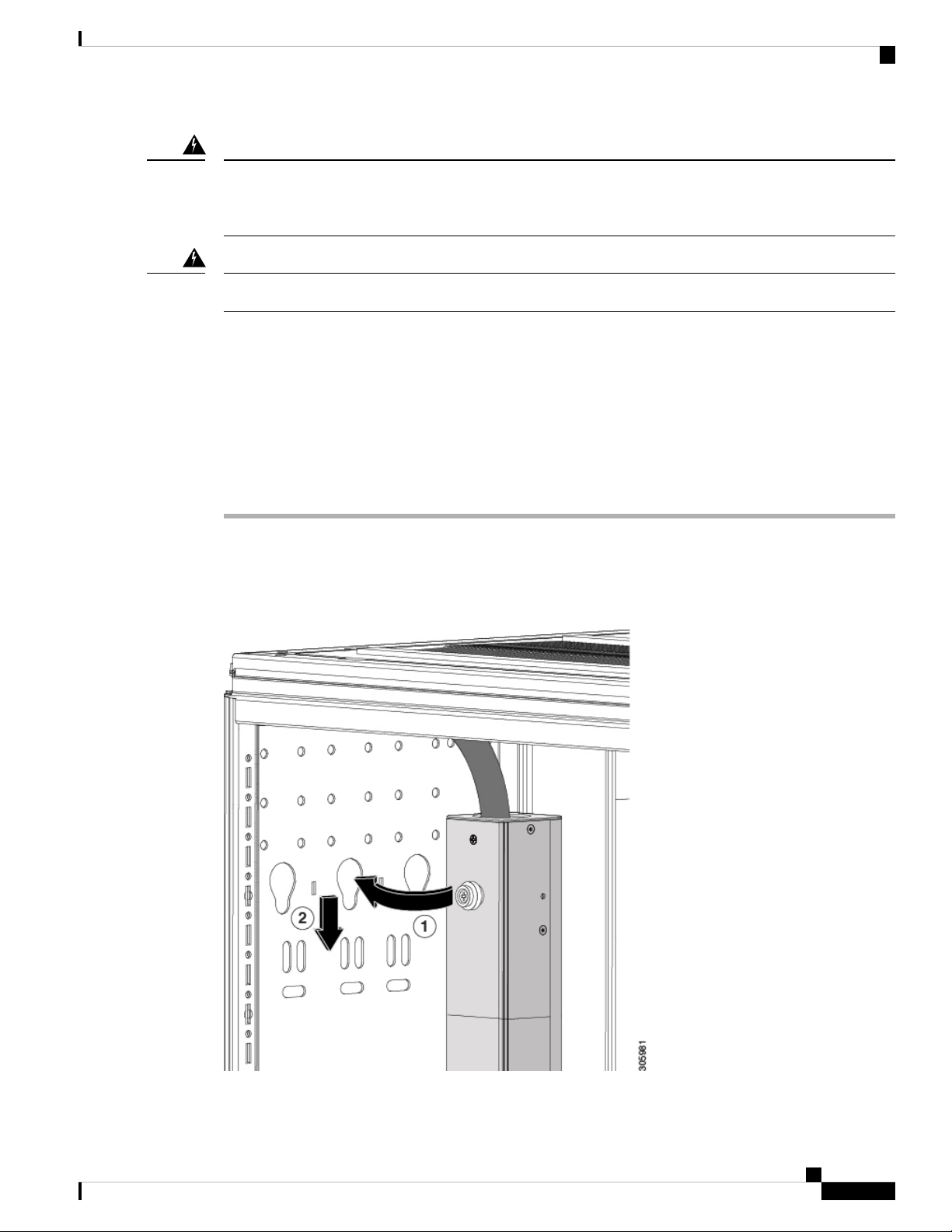
Step 1 Insert the mounting button on the back of the PDU into a key hole near the top of the PDU tray or into the
top key hole of the rear-facing flange. Callout 1 in the following figure shows the mounting button and the
key hole of the PDU tray on the side of the rack.
Figure 1: PDU Mounting Button
Installing Cisco RP-Series PDUs
3
Page 4

Installing Cisco RP-Series PDUs
Installing a Zero-U PDU
Step 2 Slide the PDU down slightly so that it locks into place in the key hole on the PDU tray (see callout 2 in the
preceding figure) or the rear-facing flange.
Step 3 Secure the lower PDU mounting button into place as in steps 1 and 2.
Step 4 Install a PDU retention bracket on the top of the PDU as shown in the following figure. Secure the bracket
to the PDU tray with the screws provided.
Figure 2: Attaching the PDU Retention Bracket to the PDU Tray
Step 5 Route the PDU power cable either through the large access opening in the back of the rack canopy.
Step 6 Connect the PDU power cord to the AC power source.
The following figure shows a single zero-U PDU installed in the PDU tray.
Figure 3: One Zero-U PDU Installed
The following figure shows three zero-U PDUs installed side-by-side in the PDU tray.
Installing Cisco RP-Series PDUs
4
Page 5

Installing Cisco RP-Series PDUs
Figure 4: Three Zero-U PDUs Installed
Installing a Zero-U PDU
The following figure shows a single zero-U PDU installed on the rear-facing flange.
Installing Cisco RP-Series PDUs
5
Page 6

Installing a 1RU or 2RU PDU
Figure 5: One Zero-U PDU Installed on the Rear-Facing Flange
Installing Cisco RP-Series PDUs
Installing a 1RU or 2RU PDU
The RP208-30M1P-4-8 PDU and the RP208-60M3P-12 PDU mount horizontally in one of the available RU
spaces.
For additional information on how to install a PDU, see the Eaton ePDU G3 Installation and Connectivity
Quick Start or the Eaton Enclosure Power Distribution Unit (ePDU) G3 - Operations Manual.
The following table provides the specifications for these PDUs. For detailed specifications and illustrations,
see PDU Specifications.
Installing Cisco RP-Series PDUs
6
Page 7

Installing Cisco RP-Series PDUs
Table 2: 1RU and 2RU PDU Specifications
Installing a 1RU or 2RU PDU
CountryPlugDescriptionProduct ID
Warning
Warning
Warning
Warning
RP208-30M1P-4-8
North AmericaL6-30P30 A, metered input, single-phase,
horizontal-mount PDU with 4 C19
and 8 C13 connectors
RP208-60M3P-12
60 A, metered input, three-phase,
horizontal mount PDU with 12 C 19
460P9
North AmericaIEC 60309
connectors
No serviceable parts inside. To avoid risk of electric shock, do not open.
Read the installation instructions before using, installing or connecting the system to the power source.
This product relies on the building’s installation for short-circuit (overcurrent) protection. To reduce risk of
electric shock or fire, ensure that the protective device is rated not greater than:
This equipment must be grounded. To reduce the risk of electric shock, never defeat the ground conductor or
operate the equipment in the absence of a suitably installed ground conductor. Contact the appropriate electrical
inspection authority or an electrician if you are uncertain that suitable grounding is available.
Warning
For Nordic countries (Norway, Finland, Sweden and Denmark) this system must be installed in a Restricted
Access Location, where the voltage of the main ground connection of all equipment is the same (equipotential
earth) and the system is connected to a grounded electrical outlet.
Warning
Connect the device to a grounded power outlet.
To install a 1RU or 2RU PDU, follow these steps:
Procedure
Step 1 Attach the four cage nuts to the interior side of the rack posts, spacing the nuts apart to the 1RU or 2RU
position, depending on which PDU you are installing.
Step 2 Use the supplied mounting screws to secure the unit in place, as shown in the following figures.
Installing Cisco RP-Series PDUs
7
Page 8

Installing a 1RU or 2RU PDU
Figure 6: Mounting the RP208-30M-P-4-8 1RU PDU
Installing Cisco RP-Series PDUs
Figure 7: Mounting the RP208-60M3P-12 2RU PDU
Installing Cisco RP-Series PDUs
8
 Loading...