

Page 1
Quick Reference Guide
QPSK D9494 Demodulator
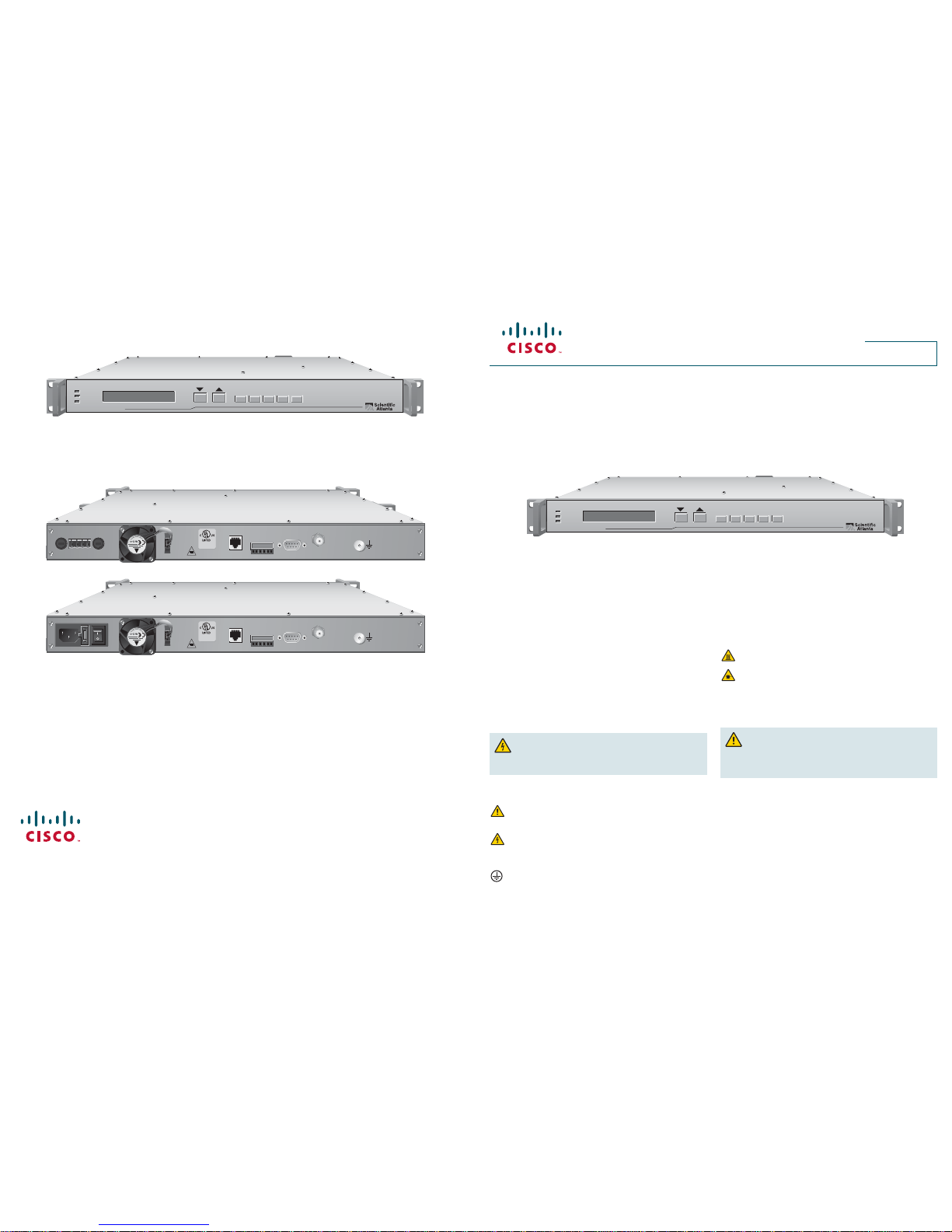
QPSK D9494 Demodulator Front Panel
Use the following diagram to assist you with the installation of the demodulator.
QPSK D9494 Demodulator Back Panels
Use the following diagrams to assist you with the installation of the demodulator, as well as the location of the connection ports.
ALARM
BURST DATA
MAC SYNC
TEST OPTIONSFREQ STATUS ENTER
QPSK Demodulator Model D9494-1
T13607
ALARM
BURST DATA
MAC SYNC
TEST OPTIONSFREQ STATUS ENTER
QPSK Demodulator Model D9494-1
T13608
QPSK D9494 Demodulator (48 VDC Model)
QPSK D9494 Demodulator (100-240 VAC Model)
POWER 120/130V 60/50Hz 2.5A
RF OUT 1 RF OUT 2 RF OUT 3 RF OUT 4
ASI IN 1 ASI IN 2 ASI IN 3 ASI IN 4
DATA 1
CRAFT
PORT
GND
10/100 BASE T
LINK ACTIVE
GIGABIT
ETHERNET
LINKACT
LINKACT
DATA 2
DATA 3
DATA 4
T4H, 250V
T
-A -V
BACKUP MAIN
T2H, 250V
A
FUSE
B
++--
RF INPUT
GND
DIAGNOSTICS
NETWORK
DATA
FUSE
FUSE
FUSE
MAJOR MINOR
NC
CNONC
C
NO
POWER - 48 VDC 24W
FAN
T
-A -V
T2H, 250V
29F9
PROFESSIONAL
VIDEO EQUIPMENT
RF INPUT
GND
DIAGNOSTICS
NETWORK
DATA
MAJOR MINOR
NC
CNONC
C
NO
100-240V ~ 60/50Hz 0.5A POWER
FAN
T
-A -V
T2H, 250V
29F9
PROFESSIONAL
VIDEO EQUIPMENT
Introduction
This quick reference guide is intended for individuals who are responsible
for installing the QPSK D9494 Demodulator into a rack unit.
For more detailed descriptions of the installation process and safety
information for this demodulator, refer to the Model D9494 DAVIC QPSK
Demodulator Installation and Operation Guide (part number 4022032).
Warning and Caution Icons
WARNING: Avoid personal injury and product damage! Do
not proceed beyond any icon until you fully understand the
indicated conditions.
The following icons alert you to important information about the safe
operation of this product.
You will fi nd this icon in the literature that accompanies this product.
This icon indicates important operating or maintenance
instructions.
You may fi nd this icon affi xed to this product and in this document
to alert you of electrical safety hazards. On this product, this icon
indicates a live terminal; the arrowhead points to the terminal
device.
You may fi nd this icon affi xed to this product. This icon indicates a
protective earth terminal.
You may fi nd this icon affi xed to this product. This icon indicates
excessive or dangerous heat.
You may fi nd this symbol affi xed to this product and in this document.
This symbol indicates an infrared laser that transmits intensitymodulated light and emits invisible laser radiation and an LED that
transmits intensity-modulated light.
Controlling the Operating Temperature
CAUTION: The operating temperature for this equipment is
32 to 122°F (0 to 50°C). Avoid damage to this product! Your warranty
is void if you operate this product above or below the maximum
specifi ed operating temperatures.
Measuring the Inlet Air Temperature
If you are concerned about inlet air temperature at the air inlet of any
demodulator, you can measure the inlet air temperature in the rack. When
measuring the temperature, ensure that all cabling is complete and that
all adjacent QPSK demodulators are installed and running.
Important: Opening the door on the back panel of the rack may have an
adverse effect on the managed airfl ow. If access to the door is not controlled,
measure the inlet air temperature with the back panel door open because
this typically redirects the airfl ow in an adverse manner.
Cisco Systems, Inc. 678 277-1120
5030 Sugarloaf Parkway, Box 465447
Lawrenceville, GA 30042 www.FLVFRcom
Cisco and the Cisco logo are registered trademarks or trademarks of Cisco and/or its aff liates in the U.S. and certain other
countries. To view a list of Cisco trademarks, go to this URL: www.cisco.com/go/trademarks
Third party trademarks mentioned are the property of their respective owners.The use of the word partner does not imply a
partnership relationship between Cisco and any other company. (1110R)
Product and service availability subject to change without notice.
© 2008,2012 Cisco Systems, Inc. All rights reserved. Printed in United States of America
September 2012 Part Number 78-4022033-01 Rev B
FINAL
Page 2

Installation and Connections
Complete steps 1 through 10 to install and connect the demodulator
into the rack unit.
Important: See the back page of this guide to view the front and
back panels of the QPSK demodulator.
1 Install the QPSK Demodulator
into a Rack
CAUTION:
• Do not to tangle or strain interconnecting cables.
• Be sure to install additional support.
• Do not stack more than eight demodulators
consecutively in the rack.
A. Unpack and inspect the demodulator.
B. Install the angle support brackets (part numbers
734845 and 734846) supplied with the demodulator.
C. Place the demodulator into the rack.
D. Insert a mounting screw through each of the four bezel
mounting holes on the front panel of the demodulator
and then into the rack.
E. Firmly tighten each mounting screw.
Important: When you use the supplied angle support
brackets, you can install the QPSK demodulators above
or below each other in the rack. These brackets provide
additional support and allow correct air circulation through
the unit.
2 Connect the Network Data Port
The Network Data port provides two-way data fl ow with
the QPSK modulator. The two-way data includes status
monitoring and control (SMC) responses, application data,
MAC Status, and SMC provisioning requests.
Use a shielded, CAT-5 Ethernet interconnect cable to
connect the Network Data ATM-25 port on the demodulator
to the modulator.
Note: The demodulator interface on the QPSK modulator
is designed to connect to up to eight QPSK demodulators.
3 Connect the Diagnostics Port
The diagnostic port connects the demodulator to a
diagnostic PC. This port is not designed to be connected
for normal operation.
A. Connect the male end of a DB-9 data cable to the
Diagnostics (craft) port on the back of the demodulator.
B. Connect the other end of a DB-9 data cable to an
available serial port on the diagnostic PC.
Note: To maintain signal clarity and strength, use a
ribbon cable no longer than 50 ft.
C. Power on the PC and activate a ProComm or
HyperTerminal window using the following modem
connection settings:
• 19200 baud
• 1 stop bit
• No parity
• 8 data bits
• No fl ow control
4 Connect the Alarm Relays
(Optional)
A. If connected, disconnect the power wires from the
power supply, or power off the unit.
WARNING: Avoid electric shock when
disconnecting the power supply. Only a qualifi ed
electrician should disconnect the power supply.
B. Determine whether the indicator trips (activates) on an
open or closed circuit (usually the external alarm has
this information).
• A simple indicator (for example, an alarm based on
a battery and beeper) would trip on a closed circuit
(use the NO and COM terminals)
• A more complex indicator (for example, a
commercial alarm system) would trip on an open
circuit (use the NC and COM terminals)
Notes:
• The alarm connections power base ratio is 2 A
at 50 V.
• The alarm connector uses a screw-cage clamp
plug with mating jack on the demodulator. The plug
accepts wire from 16 to 28 AWG.
C. Insert an indicator wire into the NO, the NC, or the
COM plug screw-cage clamp (see step B in this
section for determining which terminals to use).
Note: Make sure the screw-cage clamp closes on the
bare wire, not on the insulation.
D. Use a small slotted screwdriver to tighten the screw-
cage clamp screw.
E. Repeat steps C and D of this section for additional
connections, as needed.
F. Connect the power to the power supply.
5 Connect the RF Input Port
The RF Input port connects the demodulator to the HFC
network and to set-tops.
A. Connect one end of a 75 Ω RG-59 coaxial cable to the
RF Input port.
B. Connect the other end of the 75 Ω RG-59 coaxial
cable to an RF signal splitter in the distribution plant
(headend).
6 Connect an Earth Ground
CAUTION: The 48 VDC devices must be
connected to an earth ground.
A. Place a ground wire onto the ground lug (marked GND)
on the back of the demodulator; then, use your fi ngers
to tighten the ground lug to secure the ground wire.
B. Connect the other end of the ground wire to the rack or
earth ground.
7 Connect the Power Source
48 VDC Model
A. Verify that the DC power source to the 48 VDC model
is set to the Off position.
B. Insert the wires from the DC power source into the
screw-cage clamp. Use a small fl at-blade screwdriver
to tighten the screws at the top of the screw-cage
clamp to secure the wires.
C. Insert the plug into the mating jack on the back panel
of the demodulator.
D. Keep the DC power source set to the Off position until
you are ready to power on the demodulator.
100-240 VAC Model
A. Verify that the power switch on the back panel of the
100-240 VAC model is set to the Off position.
B. Connect the power cord to the AC power inlet on the
back panel of the demodulator.
C. Connect the other end of the power cord to an AC
electrical outlet.
D. Keep the power switch set to the Off position until you
are ready to power on the demodulator.
8 Install the Demodulator Software
For detailed information about installing the software, refer
to the QPSK Demodulator Software Installation Instructions
(part number 4022031).
9 Provision the QPSK Demodulator
on the DNCS
After you have installed and connected the QPSK
demodulator, you must provision the QPSK demodulator
on the DNCS. For detailed instructions on how to
provision the QPSK demodulator on the DNCS, refer
to the DNCS Online Help for your system release.
10 Power On the Demodulator
After you have installed, connected, and provisioned the
QPSK demodulator, power on the demodulator. The
QPSK modulator manages the QPSK demodulator, and
provides the provisioning information from the DNCS to
the demodulator after the demodulator is powered on.
FINAL
 Loading...