

Page 1

Preparing for Installation
This chapter guides you through the process of preparing for router installation.
Before installing your Cisco ASR 9901 or Cisco ASR 9001 Router, you must consider these requirements:
• Power and cabling requirements must be in place at your installation site.
• Special equipment must be available for installing the router.
• The environmental conditions that your installation site must meet to maintain normal operation.
The shipping package for the router is engineered to reduce chances of product damage that may result from
routine material handling during shipment:
• Keep the router in the shipping container until you have determined the installation site.
• The router should always be transported or stored in its shipping package in the upright position.
Inspect all items for shipping damage. If an item appears damaged, contact a Cisco customer service
representative immediately.
This chapter contains these installation topics:
• Overview, on page 1
• Safety Guidelines, on page 3
• Site Requirement Guidelines, on page 6
• Port Connection Guidelines, on page 35
Overview
Cisco ASR 9901 Router
The Cisco ASR 9901 Router is a compact high-capacity provider edge (PE) router that delivers 456 Gbps of
non-blocking, full-duplex fabric capacity in a two-rack-unit (2RU) form factor.
Note
The Cisco ASR 9901 Router supports Cisco IOS XR 64-bit releases only.
Preparing for Installation
1
Page 2
Overview
Preparing for Installation
The Cisco ASR 9901 Router has an integrated route processor (RP) and 42 fixed-configuration ports that
support the following data rates:
• 24 ports that support 1 GE (using SFP) or 10 GE (using SFP+).
Note
1GE copper SFPs are not supported in converted dual-rate ports.
• 16 ports that support 1 GE (using SFP).
Note
1GE copper SFPs operate only on 1000BASE-T rates; autonegotiation and speed
configurations are not supported.
• 2 ports that support 100 GE (using QSFP28).
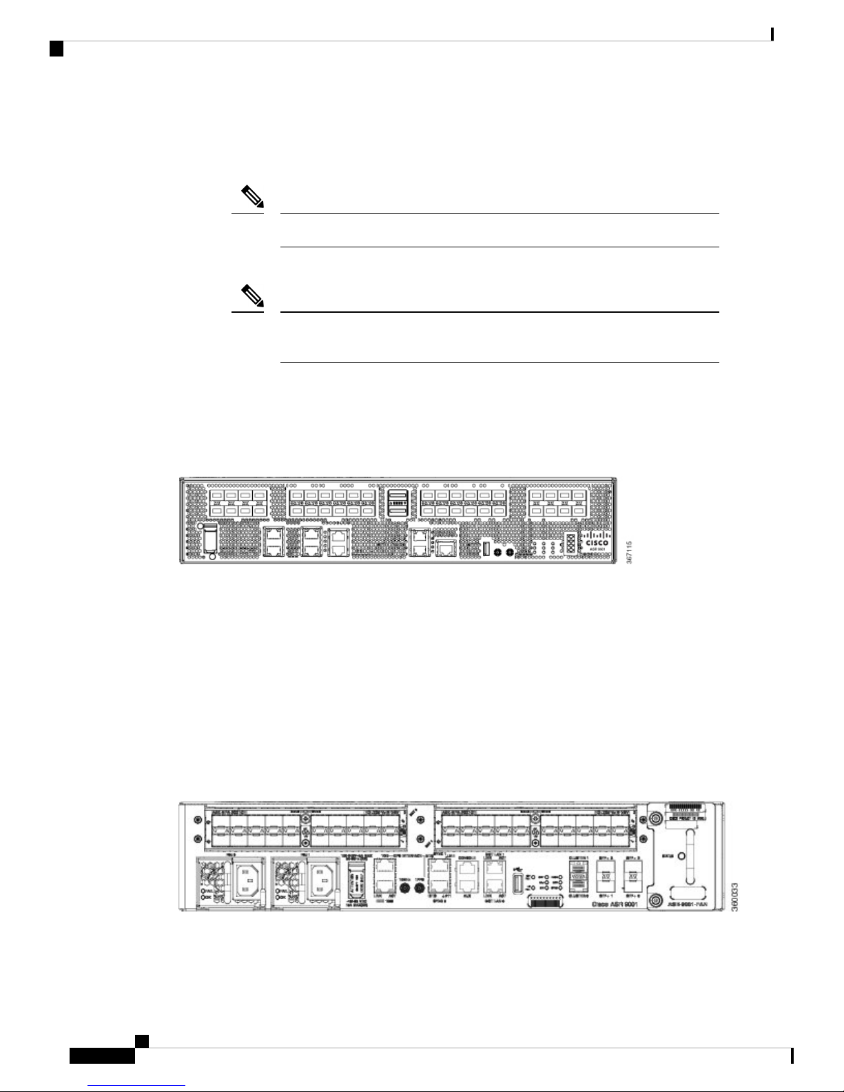
The base chassis has a GPS input for stratum-1 clocking, building integrated timing supply (BITS) ports, and
management ports. The following figure shows the front panel of the Cisco ASR 9901 Router.
Figure 1: Front Panel of the Cisco ASR 9901 Router
Cisco ASR 9001 Router
The Cisco ASR 9001 Router is a compact high-capacity provider edge (PE) router that delivers 120 Gbps of
non-blocking, full-duplex fabric capacity in a two-rack-unit (2RU) form factor. Similar to other routers in the
Cisco ASR 9000 Series, running Cisco IOS XR software images, the Cisco ASR 9001 Router delivers the
features and services found on the ASR 9000 Series platforms, allowing customers to standardize on the same
Cisco IOS XR image. The Cisco ASR 9001 Router has an integrated route processor (RP) and two modular
bays that support 1 GE, 10 GE and 40 GE modular port adapters (MPAs). The base chassis has four integrated
10 GE enhanced small form-factor pluggable (SFP+) ports, a GPS input for stratum-1 clocking, building
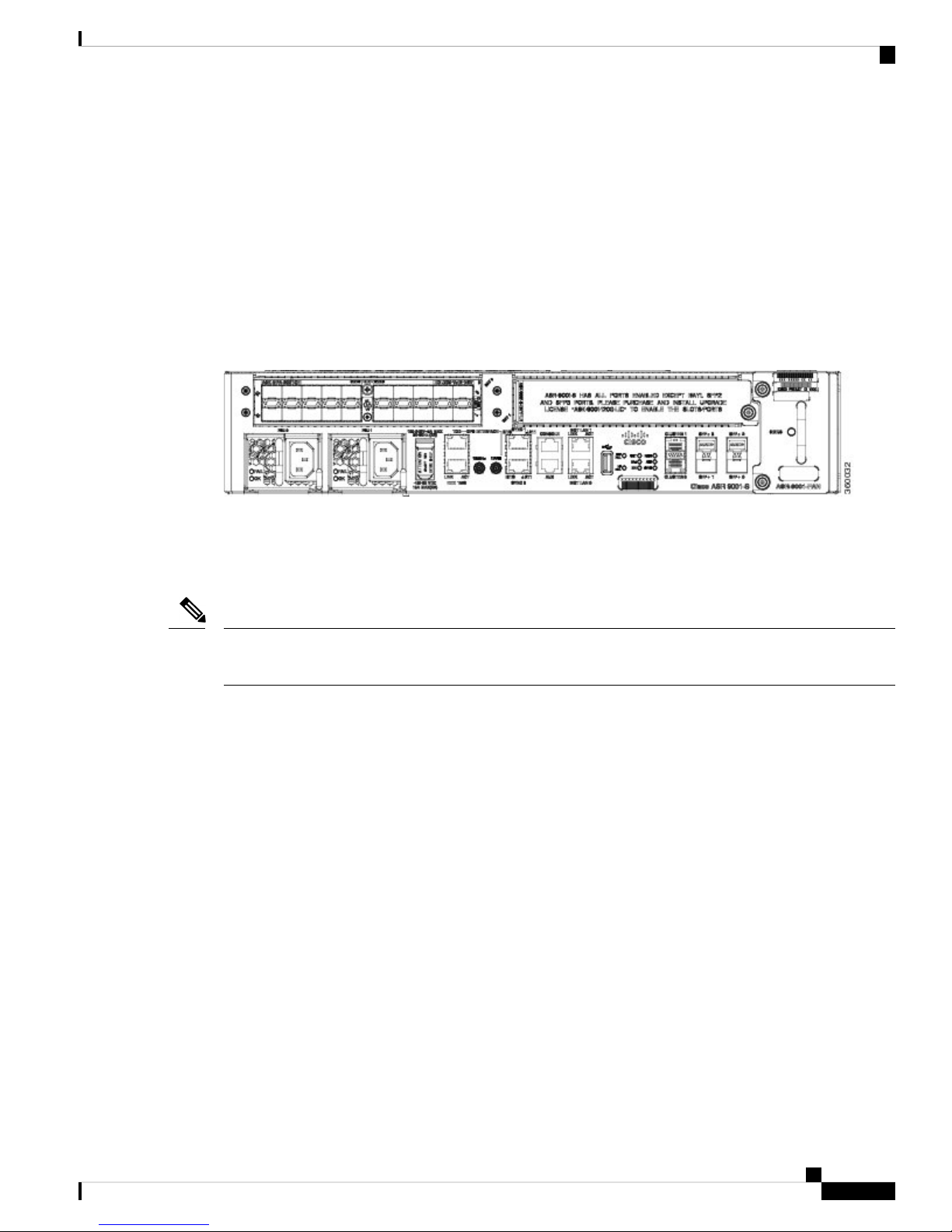
integrated timing supply (BITS) ports, and management ports. The following figure shows the front panel of
the Cisco ASR 9001 Router.
Figure 2: Front Panel of the Cisco ASR 9001 Router
Preparing for Installation
2
Page 3
Preparing for Installation
Safety Guidelines
Cisco ASR 9001-S Router
The Cisco ASR 9001-S Router is a 60 Gbps variant of the Cisco ASR 9001 Router. Similar to other routers
in the Cisco ASR 9000 Series, running Cisco IOS XR software images, the Cisco ASR 9001-S Router delivers
the features and services found on the ASR 9000 Series platforms, allowing customers to standardize on the
same Cisco IOS XR image. The Cisco ASR 9001-S Router comes standard with one modular bay (BAY 0)
that supports either a 1 GE, 10 GE, or 40 GE modular port adapters (MPAs). The chassis also comes usable
with two fixed SFP+ ports (SFP+0 and SFP+1). The second MPA slot (BAY 1) and other two SFP+ ports
(SFP+2 and SFP+3) are disabled and covered with dust caps by default. It supports the same set of features
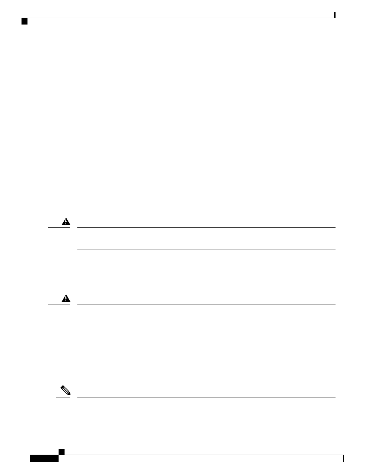
and scaling for each NPU as does the Cisco ASR 9001 Router. The following figure shows the front panel of
the Cisco ASR 9001-S Router.
Figure 3: Front Panel of the Cisco ASR 9001-S Router
In order to achieve the full bandwidth of 120 Gbps and to enable the disabled ports, a Cisco license can be
obtained. Once the license is obtained and installed, the Cisco ASR 9001-S Router must be reloaded to bring
up the full 120 Gbps capacity. For information on configuring the Cisco license for Cisco ASR 9001-S Router,
see the Cisco ASR 9001-S 120G Upgrade License Configuration Guide .
Note
The Cisco ASR 9001-S Router follows the same hardware installation procedure as the procedure for the
Cisco ASR 9001 Router, described in this document.
Safety Guidelines
Before you perform any procedure in this publication, you must review the safety guidelines in this section
to avoid injuring yourself or damaging the equipment.
Note that this section contains guidelines, and do not include every potentially hazardous situation. When you
install a router, always use caution and common sense.
General Safety Guidelines
• Never attempt to lift an object that might be too heavy for you to lift by yourself.
• Always disconnect the power source and unplug all power cables before lifting, moving, or working on
the router.
• Keep the work area clear and dust free during and after installation.
• Keep tools and router components away from walkways and equipment rack aisles.
• Do not wear loose clothing, jewelry (including rings and chains), or other items that could get caught in
the router.
• Fasten your tie or scarf and sleeves.
Preparing for Installation
3
Page 4
Compliance and Safety Information
• Operate Cisco equipment safely by using it in accordance with its electrical ratings and product usage
instructions.
• Do not work alone if potentially hazardous conditions exist.
• Always unplug power cables when performing maintenance or working on the router, unless the
replacement part is hot swappable and designed for online insertion and removal (OIR).
• Ensure that the installation of the router is in compliance with national and local electrical codes: in the
United States, National Fire Protection Association (NFPA) 70, United States National Electrical Code;
in Canada, Canadian Electrical Code, part I, CSA C22.1; in other countries, International Electrotechnical
Commission (IEC) 364, part 1 through part 7.
Compliance and Safety Information
The Cisco ASR 9901, ASR 9001, and ASR 9901-S Routers are designed to meet the regulatory compliance
and safety approval requirements. See the Regulatory Compliance and Safety Information for Cisco ASR
9000 Series Routers.
Laser Safety
Preparing for Installation
The fixed-configuration ports on the Cisco ASR 9901 and the line card ports on the Cisco ASR 9001 Router
are equipped with lasers. The lasers emit invisible radiation. Do not stare into open ports. Observe this warning
to prevent eye injury:
Warning
Invisible laser radiation may be emitted from disconnected fibers or connectors. Do not stare into beams or
view directly with optical instruments. Statement 1051
Energy Hazard
The Cisco ASR 9901 and Cisco ASR 9001 Router can be configured for a DC power source. Do not touch
terminals while they are live. Observe this warning to prevent injury.
Warning
Hazardous voltage or energy may be present on power terminals. Always replace cover when terminals are
not in service. Be sure uninsulated conductors are not accessible when cover is in place. Statement 1086
Preventing Electrostatic Discharge Damage
Many router components can be damaged by static electricity. Not exercising the proper electrostatic discharge
(ESD) precautions can result in intermittent or complete component failures. To minimize the potential for
ESD damage, always use an ESD-preventive antistatic wrist strap (or ankle strap) and ensure that it makes
good skin contact.
Note
Check the resistance value of the ESD-preventive strap periodically. The measurement should be between 1
and 10 megohms.
Preparing for Installation
4
Page 5
Preparing for Installation
Lifting Guidelines
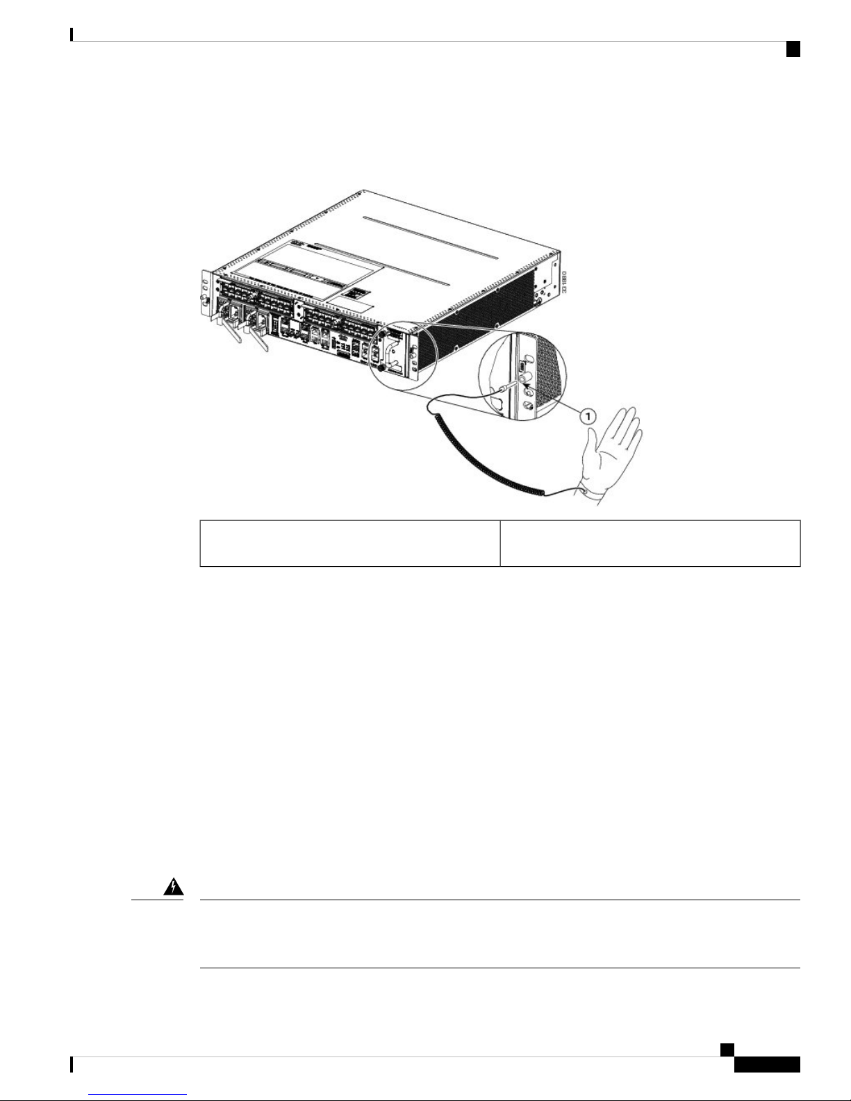
Before you perform any procedure in this guide, attach an ESD-preventive strap to your wrist and connect
the leash to the chassis as shown in the figure below.
Figure 4: Connecting an ESD-Preventive Wrist Strap to the Cisco ASR 9001 Router Chassis
1
Lifting Guidelines
A fully-configured Cisco ASR 9901 can weigh as much as 55.97 pounds (25.4 kg). A fully-configured Cisco
ASR 9001 Router can weigh as much as 37.91 pounds (17.2 kg). These systems are not intended to be moved
frequently. Before you install the router, ensure that you have planned the installation and migration of the
router into your network so that you can avoid having to move the router later to accommodate power sources
and network connections.
Use these lifting guidelines to avoid injury to yourself or damage to the equipment:
• Do not lift equipment alone; have another person help you to lift the equipment.
• Ensure that your footing is solid; balance the weight of the object between your feet.
• Lift the equipment slowly; never move suddenly or twist your body as you lift.
• Keep your back straight and lift with your legs, not your back. When bending down to lift equipment,
bend at the knees (not at the waist), to reduce the strain on your lower back muscles.
Warning
To prevent personal injury or damage to the chassis, never attempt to lift or tilt the chassis using the
handles on modules (such as power supplies, fans, or cards); these types of handles are not designed to
support the weight of the unit. Statement 1032
Location of chassis socket for ESD strap on the Cisco
ASR 9001 Router
Preparing for Installation
5
Page 6

Site Requirement Guidelines
Site Requirement Guidelines
These sections contain the site requirement guidelines that you should be familiar with before installing the
router:
Site Layout and Equipment Dimensions
To help maintain trouble-free operation, adhere to these precautions and guidelines when planning your rack
installation:
• Install the system in a restrictive access location with means for a permanent grounding.
• Ensure the site of the rack includes provisions for source AC or DC power, grounding, and network
interface cables.
• Allow sufficient space to work around the rack during the installation. You need at least 3 feet (91.44
cm) adjacent to the rack to move, align, and insert the chassis.
Preparing for Installation
• Maintain at least 24 inches (61 cm) of clearance in front of, and behind the chassis for maintenance after
installation.
• To mount the router between two posts or rails, the usable aperture (the width between the inner edges
of the two mounting flanges) must be at least 17.7 inches (45 cm) for the Cisco ASR 9001 Router and
at least 17.75 inches (45.09 cm) for the Cisco ASR 9901 Router.
• Height of the Cisco ASR 9901 Router and Cisco ASR 9001 Router is 3.47 inches (8.8 cm).
• When fully populated with cards, the router can weigh as much as 37.91 pounds (17.2 kg). To maintain
equipment rack stability and to ensure your safety, the rack is provided with stabilizing devices. Make
sure you install the stabilizers before installing the router.
• If you use a telco-style rack, the weight of the chassis is cantilevered off the two rack posts. Make sure
that:
• Weight of the router does not make the frame unstable.
• Frame is bolted to the floor and is secured to the building structure using either wall brackets or
overhead brackets.
• When mounting the router in a telco-style rack or 4-post rack, be sure to use all the screws provided to
secure the chassis to the rack posts.
• Install the cable-management brackets included with the router to keep cables organized. Be sure to use
appropriate strain-relief methods to protect cables and equipment connections.
• To avoid noise interference in network interface cables, do not route them directly across or along power
cables.
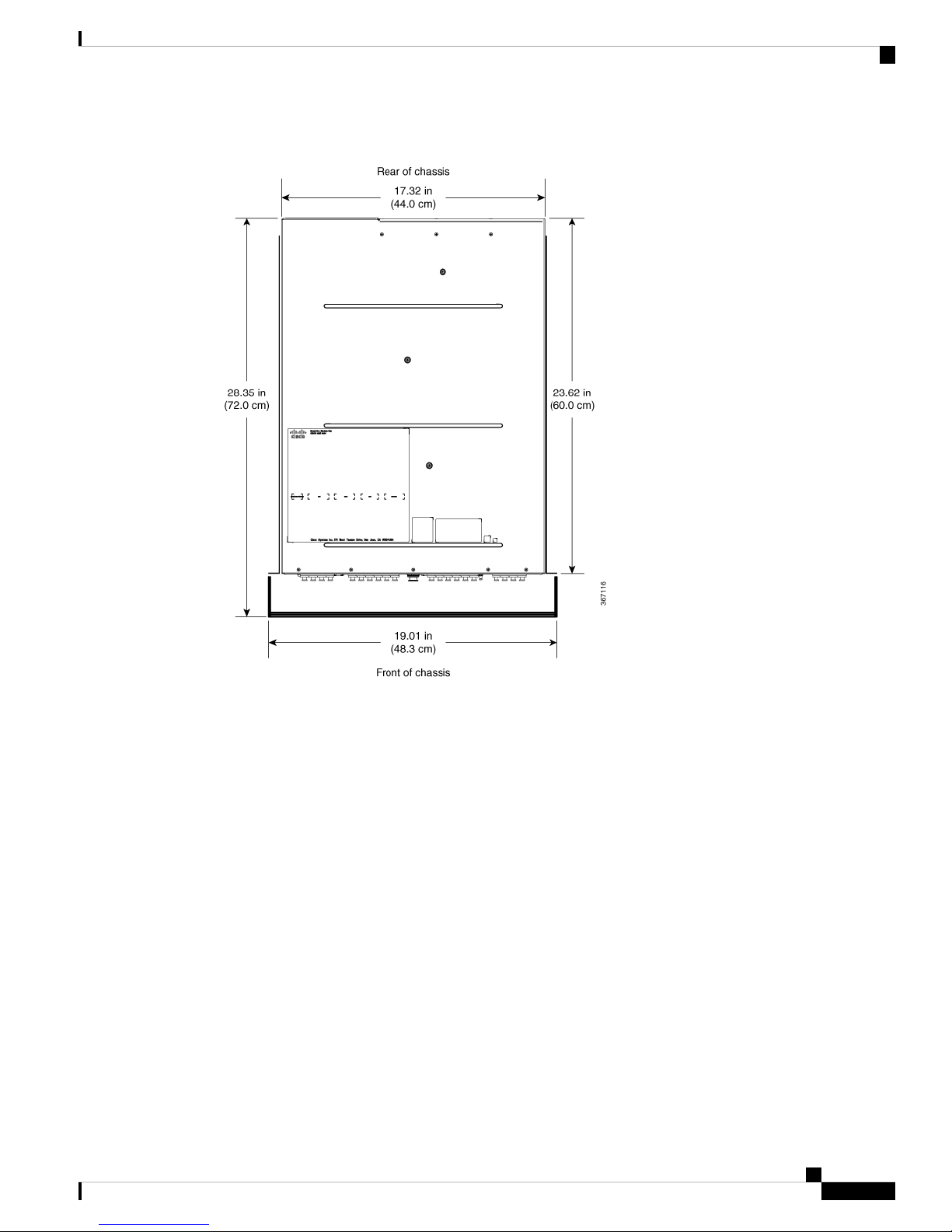
The following figure shows the top-down view chassis dimensions of the Cisco ASR 9901 Router.
Preparing for Installation
6
Page 7
Preparing for Installation
Site Layout and Equipment Dimensions
Figure 5: Cisco ASR 9901 Router Chassis Footprint and Dimensions—Top View
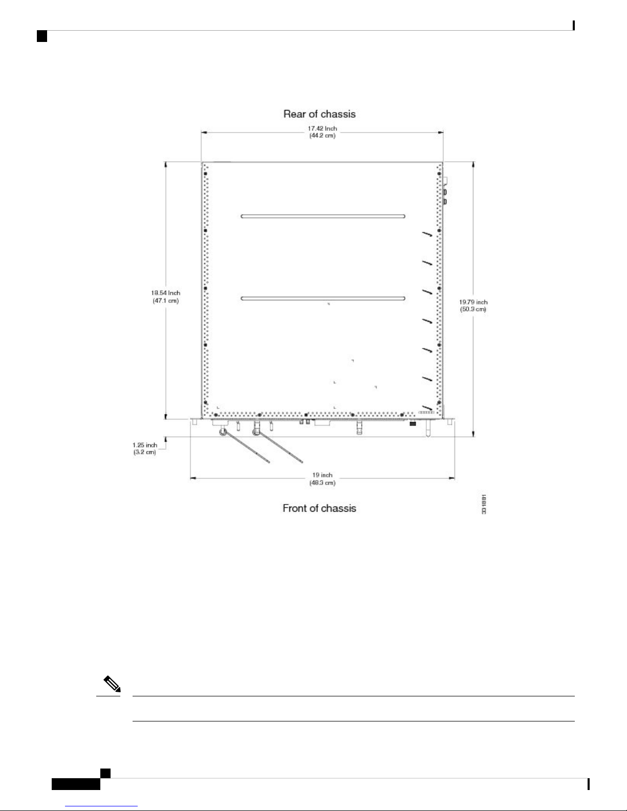
The following figure shows the top-down view chassis dimensions of the Cisco ASR 9001 Router.
Preparing for Installation
7
Page 8
Site Wiring Guidelines
Preparing for Installation
Figure 6: Cisco ASR 9001 Router Chassis Footprint and Dimensions—Top View
Site Wiring Guidelines
When planning the location of the router, consider distance limitations for signaling, electromagnetic
interference (EMI), and connector compatibility. If the wiring is run for any significant distance in an
electromagnetic field, interference can occur between the field and the signals on the wires. Poor wiring can
cause:
• Radio interference emanating from the wires.
• Strong EMI, especially when caused by lightning or radio transmitters. EMI can destroy the signal drivers
and receivers in the router, and can even create an electrical hazard by conducting power surges through
lines and into equipment.
Note
To predict and remedy strong EMI, you may need to consult with radio frequency interference (RFI) experts.
Preparing for Installation
8
Page 9

Preparing for Installation
Site wiring is unlikely to emit radio interference if you use twisted-pair cable with good distribution of
grounding conductors. Use a high-quality twisted-pair cable with one ground conductor for each data signal,
when applicable.
Give special consideration to the effect of lightning strikes in your vicinity, especially if the wiring exceeds
recommended distances, or if it passes between buildings. The electromagnetic pulse (EMP) caused by lightning
or other high-energy phenomena can easily induce enough energy into unshielded conductors, and destroy
electronic devices. If you have experienced EMP problems in the past, you may want to consult experts in
electrical surge suppression and shielding.
Most data centers cannot resolve infrequent, but potentially catastrophic, problems without pulse meters and
other special equipment. In addition, these problems can take a great deal of time to identify and resolve. We
recommend that you take the necessary precautions to avoid these problems by providing a properly grounded
and shielded environment, with special attention to issues of electrical surge suppression.
Chassis Air Flow Guidelines
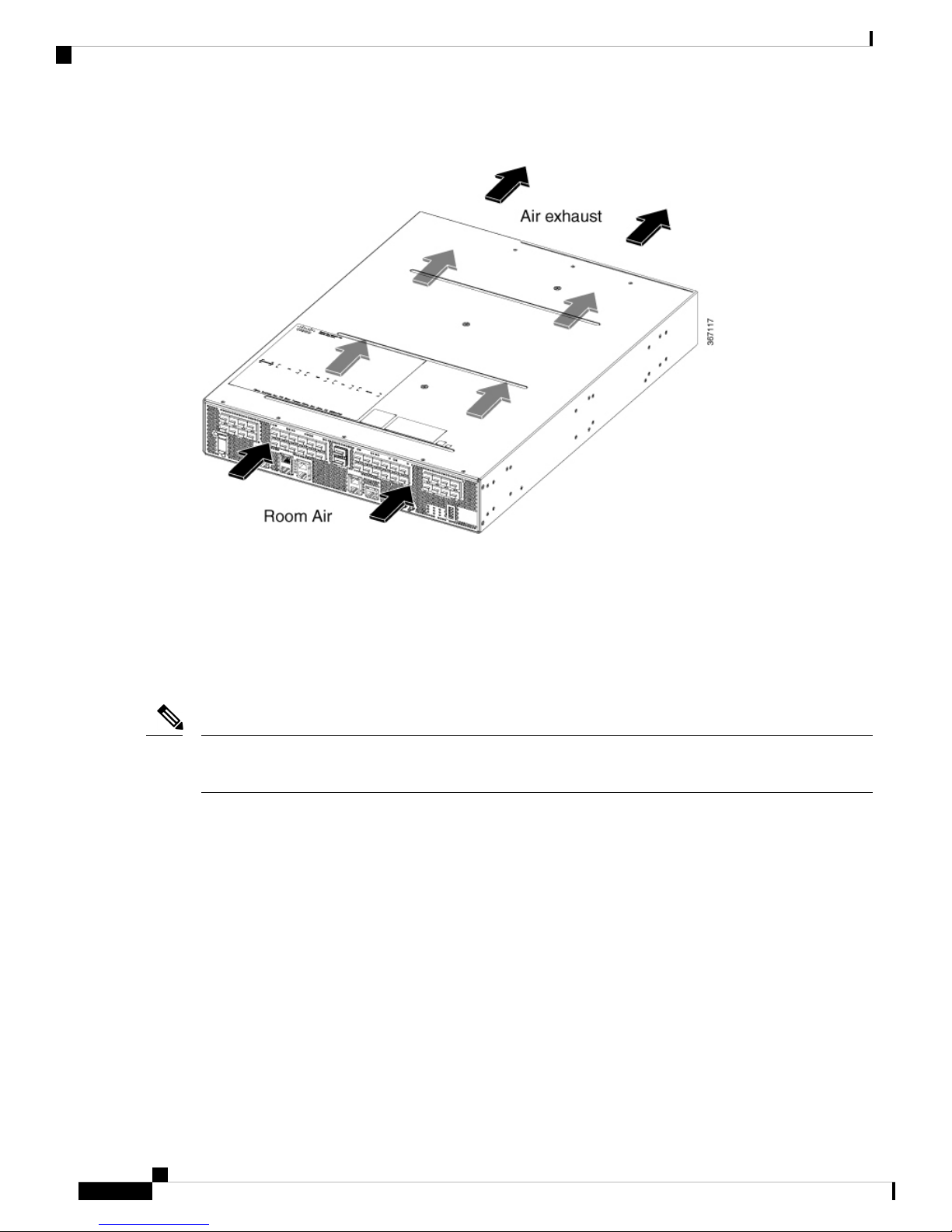
Cisco ASR 9901 Router
Chassis Air Flow Guidelines
Cool air is circulated front-to-back through the Cisco ASR 9901 Router by three fan trays located in the rear
of the router (see the following figure).
The fan trays maintain acceptable operating temperatures for the internal components by drawing in cool air
through the vents, and circulating the air through the chassis. Each power supply is also equipped with fans
that draw cool air into the front of the power supply and force warm air out of the air exhaust.
Note
See the following section for details on air flow clearance requirements for installation in an enclosed 4-post
rack.
Preparing for Installation
9
Page 10
Chassis Air Flow Guidelines
Figure 7: Air Flow Path through the Cisco ASR 9901 Router
Preparing for Installation
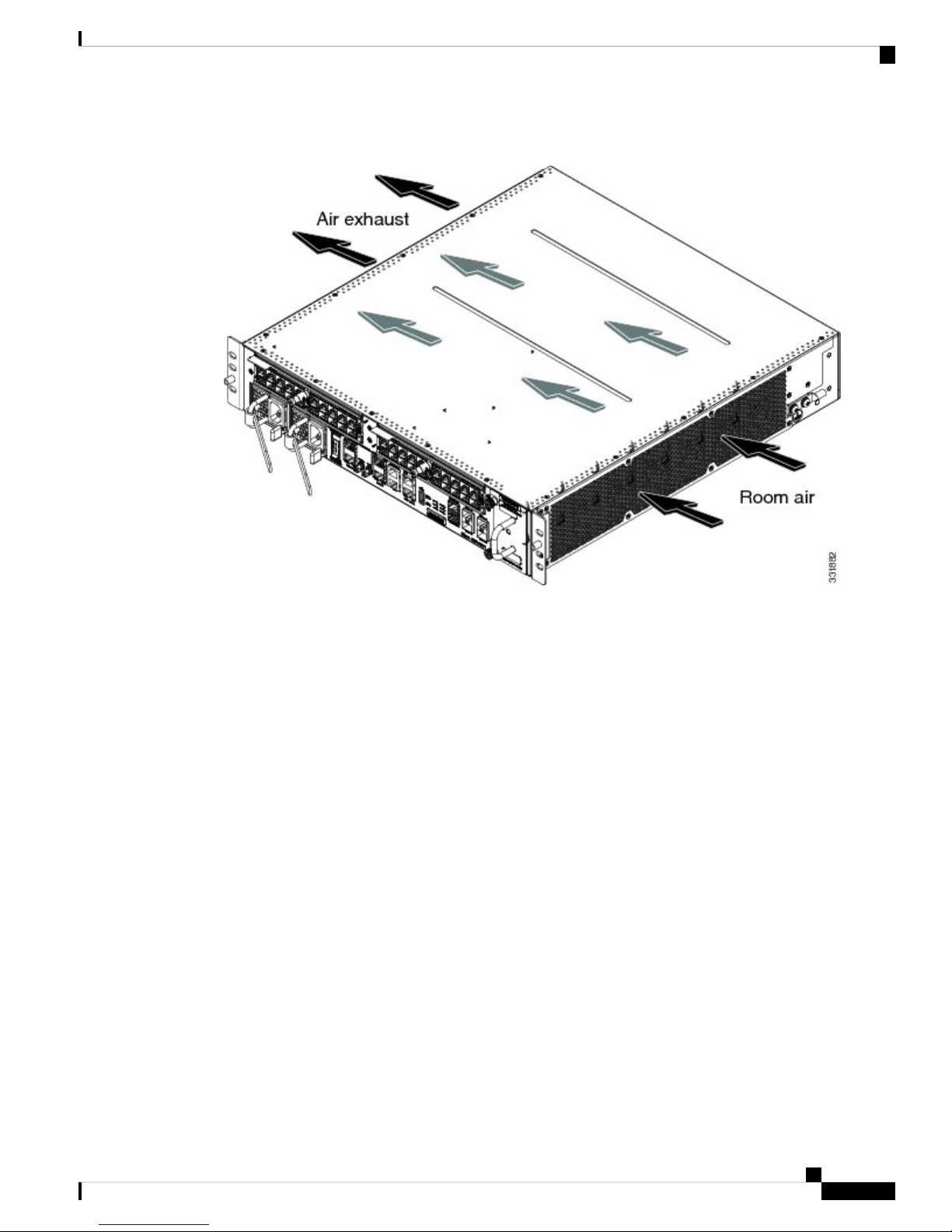
Cisco ASR 9001 Router
Cool air is circulated through the Cisco ASR 9001 Router by one fan tray located along the right side of the
router (see the following figure).
The fan tray maintains acceptable operating temperatures for the internal components by drawing in cool air
through the vents, and circulating the air through the chassis. Each power supply is also equipped with fans
that draw cool air into the front of the power supply and force warm air out of the air exhaust.
Note
See the following section for details on air flow clearance requirements for installation in an enclosed 4-post
rack.
Preparing for Installation
10
Page 11
Preparing for Installation
Rack-Mounting and Air Flow Clearance Guidelines
Figure 8: Air Flow Path through the Cisco ASR 9001 Router
When selecting a site to install the router, observe these guidelines:
• Dust free area—Site should be as dust free as possible. Dusty environments can clog the power supply
intake vents, reducing the cooling air flow through the router. Clogged filters and vents can cause an
over-temperature condition in the router.
• Unrestricted air flow—Allow sufficient air flow by maintaining a minimum of 6 inches (15.24 cm) of
clearance at both the inlet and exhaust openings on the chassis and the power modules. If the air flow is
blocked or restricted, or if the inlet air is too warm, an over-temperature condition can occur within the
router. Under extreme conditions, the environmental monitoring system powers off the router to protect
the components.
Rack-Mounting and Air Flow Clearance Guidelines
The router can be mounted in most 2-post, 4-post, or telco-style 19-inch equipment racks that comply with
the Electronics Industries Association (EIA) standard for equipment racks (EIA-310-D). The rack must have
at least two posts with mounting flanges to mount the router chassis. The distance between the center lines
of the mounting holes on the two mounting posts must be 18.31 inches ± 0.06 inch (46.50 cm ± 0.15 cm).
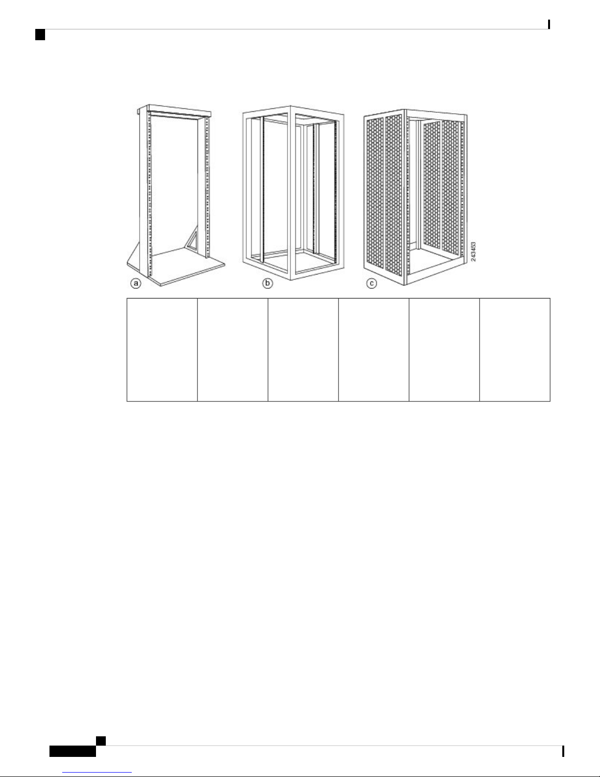
The following figure shows examples of typical 2-post, 4-post, and telco-type equipment racks.
Preparing for Installation
11
Page 12
Telco 2-Post Rack
Preparing for Installation
Figure 9: Equipment Rack Types
Telco 2-Post Rack
bTelco-style racka
cFree-standing,
4-post open rack
with two
mounting posts
in the front, two
mounting posts
Free-standing
enclosed rack
with perforated
sides and two
mounting posts
in the front
in the back or
along each side
Item a in the above figure shows a telco-style rack. The telco-style rack is an open frame consisting of two
posts tied together by a cross-bar at the top and a floor-stand at the bottom.
This type of rack is usually secured to the floor, and sometimes to an overhead structure or wall for additional
stability. The router chassis can be installed in the telco-style rack only in a front-mounted position.
Cisco ASR 9901 Router
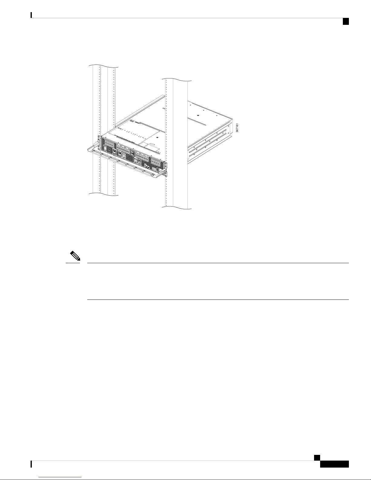
The Cisco ASR 9901 Router can be installed in 19-inch or 23-inch (with extension adapter plates) telco-style
racks. The chassis is supported by slide rails that are installed on the rear of the rack posts. Mounting brackets
are installed on the sides of the chassis and are inserted along the slide rails. The mounting brackets are then
secured to the front of the rack posts (see the following figure).
Preparing for Installation
12
Page 13
Preparing for Installation
Telco 2-Post Rack
Figure 10: Cisco ASR 9901 Router Mounted in a 2-Post Rack
Cisco ASR 9001 Router
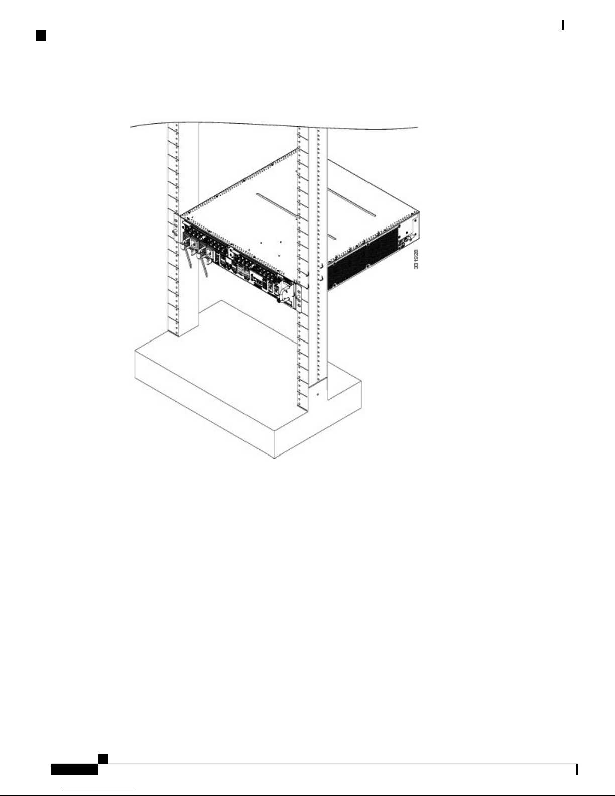
In the front-mounted position, you secure the chassis rack-mounting brackets directly to the rack posts (see
the following figure).
Note
The mounting brackets on the Cisco ASR 9001 Router chassis have a pair of holes at the top and bottom of
each bracket and three slots (elongated holes). If the Cisco ASR 9001 Router is to be mounted in a 2-post
19-inch rack, you must first use the holes to locate and position the brackets on the rack. Insert screws through
the bracket holes into the rack before inserting screws through the bracket slots.
Preparing for Installation
13
Page 14
Open 4-Post Rack
Preparing for Installation
Figure 11: Cisco ASR 9001 Router Mounted in a 2-Post Rack
Open 4-Post Rack
Item b in Figure 9: Equipment Rack Types, on page 12 shows a free-standing, 4-post open rack with two
mounting posts in the front and two mounting posts in the back or along the side. The mounting posts in this
type of rack are often adjustable so that you can position the rack-mounted unit within the depth of the rack
rather than flush-mount it with the front of the rack.
Two adjustable 4-post slide rails and two side-mounted guide brackets are provided for mounting the Cisco
ASR 9901 Router in a 4-post rack. Two rear mounting brackets are provided for mounting the Cisco ASR
9001 Router in a 4-post rack.
Enclosed Rack with Perforated Sides
Item c in Figure 9: Equipment Rack Types, on page 12 shows a free-standing 4-post enclosed rack with
perforated sides and two mounting posts in the front.
Preparing for Installation
14
Page 15

Preparing for Installation
Air Flow Guidelines for Enclosed Rack Installation
Caution
Do not install the Cisco ASR 9901 or Cisco ASR 9001 Router in any type of fully-enclosed rack that does
not have the required perforated sides or doors; the router requires an unobstructed flow of cooling air to
maintain acceptable operating temperatures for its internal components. Installing the router in any type of
fully-enclosed rack without proper perforation could disrupt the air flow, trap heat next to the chassis, and
cause an over-temperature condition inside the router.
Air Flow Guidelines for Enclosed Rack Installation
To install a Cisco ASR 9901 or Cisco ASR 9001 Router in an enclosed cabinet, the front and rear doors of
the cabinet must be removed or be perforated with a minimum of 65% open area (70% for ETSI 800mm
racks).
Cisco ASR 9901
If you are mounting the Cisco ASR 9901 chassis in a 2-post or 4-post enclosed cabinet, ensure that you have
minimum of 6 inches (15.24 cm) of clearance in the front and rear of the chassis.
The following figure shows the air flow clearance requirements for mounting the Cisco ASR 9901 Router in
a 2-post or 4-post enclosed rack.
Figure 12: ASR 9901 Clearance Requirements for an Enclosed Rack Installation
Preparing for Installation
15
Page 16

Temperature and Humidity Guidelines
Cisco ASR 9001
If you are mounting the Cisco ASR 9001 chassis in a 4-post enclosed cabinet, ensure that you have these
clearances around the chassis:
• Rear: Minimum of 3.15 inches (8.00 cm) of clearance
• Sides: Minimum of 6 inches (15.24 cm) of clearance on each side of the chassis.
The following figure shows the side and rear chassis air flow clearance requirements for mounting the Cisco
ASR 9001 Router in a 4-post enclosed rack.
Figure 13: ASR 9001 Clearance Requirements for an Enclosed 4-Post Rack Installation
Preparing for Installation
Temperature and Humidity Guidelines
The operating and nonoperating environmental site requirements are listed in Environmental Specifications.
The router normally operates within the ranges listed in Environmental Specifications; however, if a temperature
measurement is approaching a minimum or maximum parameter, it indicates a potential problem. Maintain
normal operation by anticipating and correcting environmental anomalies before they approach critical values,
by properly planning and preparing your site before you install the router.
Preparing for Installation
16
Page 17

Preparing for Installation
Power Connection Guidelines
You can configure the router with either an AC-input or DC-input power subsystem, so the site power source
requirements differ depending on the power subsystem in your router. Ensure all power connection wiring
conforms to the rules and regulations in the National Electrical Code (NEC) as well as local codes.
Power Connection Guidelines
Caution
Each Cisco ASR 9901 or Cisco ASR 9001 Router is powered by only one type of input: AC or DC. A hybrid
(AC+DC) power configuration is not supported.
Caution
Proper grounding is necessary to avoid damage from lightning and power surges. See NEBS Supplemental
Unit Bonding and Grounding Guidelines, on page 34 for grounding requirements.
AC Powered Routers
Cisco ASR 9901
AC power modules operate in the input range of 200 VAC to 240 VAC, 50 to 60 Hz and require a minimum
service of:
Each of the AC power inputs requires a separate dedicated branch circuit. For a list of the nominal and
acceptable value ranges for source AC power, see AC Input Voltage Range.
The following table lists the AC-input power cord options, specifications, and Cisco product numbers for the
Cisco ASR 9901 AC-input power supply modules. This table also references power cord illustrations. For
more information on Cisco product numbers (PIDs) and their detailed description of power cords, refer to
Dynamic Configuration Tool.
• 15 A for operation in North America and Japan
• 10 A for international operation
• 13 A for operation in the UK
Table 1: AC-Input Power Cord Options for Cisco ASR 9901 Router
Power Cord RatingLengthPart NumberLocale
CAB-AC-16A-SG-ARArgentina
16A, 250 VAC14 ft (4.26
m)
CAB-AC-16A-SG-AZAustralia
16A, 250 VAC14 ft (4.26
m)
CAB-AC-16A-SG-BRBrazil
16A, 250 VAC14 ft (4.26
m)
CAB-AC-16A-SG-CHChina
16A, 250 VAC14 ft (4.26
m)
Preparing for Installation
17
Page 18

AC Powered Routers
Preparing for Installation
Power Cord RatingLengthPart NumberLocale
CAB-AC-16A-SG-EUEurope
16A, 250 VAC14 ft (4.26
m)
CAB-AC-16A-SG-INDIndia
16A, 250 VAC14 ft (4.26
m)
CAB-AC-16A-SG-INInternational/UK
16A, 250 VAC14 ft (4.26
m)
CAB-AC-16A-SG-ISIsrael
16A, 250 VAC14 ft (4.26
m)
CAB-AC-16A-SG-ITItaly
16A, 250 VAC14 ft (4.26
m)
CAB-AC-16A-SG-JPNJapan
16A, 250 VAC14 ft (4.26
m)
CAB-AC-16A-SG-SASouth Africa
16A, 250 VAC14 ft (4.26
m)
CAB-AC-16A-SG-SWSwitzerland
16A, 250 VAC14 ft (4.26
m)
CAB-AC-16A-SG-UKUK
16A, 250 VAC14 ft (4.26
m)
operation
operation
operation
operation
Distribution unit (PDU)
source plug
CAB-AC-20A-SG-USNorth America (non locking) 110 VAC
20A, 110 VAC14 ft (4.26
m)
CAB-AC-20A-SG-US1North America (locking) 125 VAC
20A, 125 VAC14 ft (4.26
m)
CAB-AC-20A-SG-US2North America (non locking) 200-240 VAC
20A, 250 VAC14 ft (4.26
m)
CAB-AC-20A-SG-US3North America (locking) 200-240 VAC
20A, 250 VAC14 ft (4.26
m)
CAB-AC-20A-SG-US4North America 277 VAC operation
20A, 277 VAC14 ft (4.26
m)
CAB-AC-20A-SG-C20North America Cabinet Jumper Power
20A, 250 VAC14 ft (4.26
m)
CAB-HV-25A-SG-US2North America, Ring Terminal source plug
14 ft (4.26
m)
CAB-HV-25A-SG-IN2International IEC/EU, Ring Terminal
14 ft (4.26
m)
CAB-HV-25A-SG-IN3International IEC/EU
20A, 300 VAC/500
VDC
20A, 300 VAC/500
VDC
20A, 300 VAC14 ft (4.26
m)
Preparing for Installation
18
Page 19

Preparing for Installation
AC Powered Routers
AC Power Cord Illustrations for Cisco ASR 9901 Router
This section contains the AC power cord illustrations, as described in the above table. Note that an AC power
cord may be used with several power supplies.
Figure 14: CAB-AC-16A-SG-AR Power Cord
Figure 15: CAB-AC-16A-SG-AZ Power Cord
Figure 16: CAB-AC-16A-SG-BR Power Cord
Preparing for Installation
19
Page 20

AC Powered Routers
Preparing for Installation
Figure 17: CAB-AC-16A-SG-CH Power Cord
Figure 18: CAB-AC-16A-SG-EU Power Cord
Figure 19: CAB-AC-16A-SG-IND Power Cord
Preparing for Installation
20
Page 21

Preparing for Installation
AC Powered Routers
Figure 20: CAB-AC-16A-SG-IN Power Cord
Figure 21: CAB-AC-16A-SG-IS Power Cord
Figure 22: CAB-AC-16A-SG-IT Power Cord
Preparing for Installation
21
Page 22

AC Powered Routers
Preparing for Installation
Figure 23: CAB-AC-16A-SG-JPN Power Cord
Figure 24: CAB-AC-16A-SG-SA Power Cord
Figure 25: CAB-AC-16A-SG-SW Power Cord
Preparing for Installation
22
Page 23

Preparing for Installation
AC Powered Routers
Figure 26: CAB-AC-16A-SG-UK Power Cord
Figure 27: CAB-AC-20A-SG-US Power Cord
Figure 28: CAB-AC-20A-SG-US1 Power Cord
Preparing for Installation
23
Page 24

AC Powered Routers
Preparing for Installation
Figure 29: CAB-AC-20A-SG-US2 Power Cord
Figure 30: CAB-AC-20A-SG-US3 Power Cord
Figure 31: CAB-AC-20A-SG-US4 Power Cord
Preparing for Installation
24
Page 25

Preparing for Installation
AC Powered Routers
Figure 32: CAB-AC-20A-SG-C20 Power Cord
Figure 33: CAB-HV-25A-SG-US2 Power Cord
Figure 34: CAB-HV-25A-SG-IN2 Power Cord
Preparing for Installation
25
Page 26

AC Powered Routers
Preparing for Installation
Figure 35: CAB-HV-25A-SG-IN3 Power Cord
Cisco ASR 9001
AC power modules operate in the input range of 100 VAC to 240 VAC, 50 to 60 Hz and require a minimum
service of:
• 15 A for operation in North America and Japan
• 10 A for international operation
• 13 A for operation in the UK
Each of the AC power inputs requires a separate dedicated branch circuit. For a list of the nominal and
acceptable value ranges for source AC power, see AC Input Voltage Range.
The following table lists the AC-input power cord options, specifications, and Cisco product numbers for the
Cisco ASR 9001 AC-input power supply modules. This table also references power cord illustrations. For
more information on Cisco product numbers (PIDs) and their detailed description of power cords, refer to
Dynamic Configuration Tool.
Table 2: AC-Input Power Cord Options for ASR 9001 Router
Power Cord RatingLengthPart NumberLocale
15 A, 250 V8.2 feet (2.5 m)CAB-ACUSA
15 A, 250 V8.2 feet (2.5 m)CAB-L620P-C13-JPNJapan
10 A, 250 V8.2 feet (2.5 m)CAB-ACAAustralia
10 A, 250 V8.2 feet (2.5 m)CAB-ACIItaly
10 A, 250 V8.2 feet (2.5 m)CAB-ACRArgentina
Preparing for Installation
26
10 A, 250 V8.2 feet (2.5 m)CAB-ACSSwitzerland
13 A, 250 V8.2 feet (2.5 m)CAB-ACUUK
10 A, 250 V8.2 feet (2.5 m)CAB-ACCChina
10 A, 250 V8.2 feet (2.5 m)CAB-ACSASouth Africa/India
Page 27

Preparing for Installation
AC Powered Routers
Power Cord RatingLengthPart NumberLocale
10 A, 250 V8.2 feet (2.5 m)CAB-9K10A-EUEurope
10 A, 250 V8.2 feet (2.5 m)SFS-250V-10A-ISIsrael
AC Power Cord Illustrations for Cisco ASR 9001 Router
This section contains the AC power cord illustrations, as described in the above table. Note that an AC power
cord may be used with several power supplies.
Figure 36: AC Power Cord CAB-AC
Figure 37: AC Power Cord CAB-L620P-C13-JPN
Figure 38: AC Power Cord CAB-ACA
Preparing for Installation
27
Page 28

AC Powered Routers
Preparing for Installation
Figure 39: AC Power Cord CAB-ACI
Figure 40: AC Power Cord CAB-ACR
Figure 41: AC Power Cord CAB-ACS
Preparing for Installation
28
Page 29

Preparing for Installation
AC Powered Routers
Figure 42: AC Power Cord CAB-ACU
Figure 43: AC Power Cord CAB-ACC
Figure 44: AC Power Cord CAB-ACSA
Preparing for Installation
29
Page 30

DC Powered Router
Preparing for Installation
Figure 45: AC Power Cord CAB-9K10A-EU
Figure 46: AC Power Cord SFS-250V-10A-IS
DC Powered Router
Connections to DC power modules are rated at 20 A maximum. The system accepts a nominal input voltage
of –48 VDC with an operational tolerance range of –40.5 VDC to –72 VDC. One dedicated, commensurately
rated DC power source is required for each power module connection.
Power connections to the each DC power module requires two cables: one source cable and one return cable.
For DC power cables, we recommend that you use 20-A-rated, high-strand-count copper wire cables.
The length of the cables depends on your router location from the source power.
Note
DC power cables are not available from Cisco, but they are available from external commercial cable vendors.
You must terminate DC power cables using terminal blocks. The terminal blocks are supplied along with the
DC power supply modules from Cisco.
The figures below show the types of terminal blocks required for DC-input cable connections for the Cisco
ASR 9901 Router and Cisco ASR 9001 Router.
Preparing for Installation
30
Page 31

Preparing for Installation
DC Powered Router
Figure 47: Cisco ASR 9901 DC Power Cable Terminal Block
Figure 48: Cisco ASR 9001 DC Power Cable Terminal Block
Caution
Warning
Warning
The figure below shows DC power source cable connections for single DC power module.
To avoid shock hazard, be sure to apply shrink wrap tubing around the wire entry area of the terminal block.
Hazardous voltage or energy may be present on power terminals. Always replace cover when terminals
are not in service. Be sure uninsulated conductors are not accessible when cover is in place. Statement
1086
Only trained and qualified personnel should be allowed to install, replace, or service this equipment.
Statement 1030
Preparing for Installation
31
Page 32

DC Powered Router
Preparing for Installation
Figure 49: Cisco ASR 9901 DC Power Source Cabling Scheme for a Single DC Power Module
Preparing for Installation
32
Page 33

Preparing for Installation
DC Powered Router
Figure 50: Cisco ASR 9001 DC Power Source Cabling Scheme for a Single DC Power Module
Caution
The color coding of the source DC power cable leads depends on the color coding of the site DC power source.
Because there is no color code standard for source DC wiring, be sure that power source cables are connected
to the power modules using the proper positive (+) and negative (–) polarity:
• In some cases, the source DC cable leads might have a positive (+) or a negative (–) label. This is a
relatively safe indication of the polarity, but you must also verify the polarity by measuring the voltage
between the DC cable leads . Be sure that the positive (+) and negative (–) cable leads match the positive
(+) and negative (–) labels on the power module when making the measurement.
• Green (or green and yellow) cable typically indicates that it is a ground cable.
DC power modules contain reverse voltage protection circuitry to prevent damage to the power module if it
detects a reverse polarity condition. No damage should occur from reverse polarity, but you should correct a
reverse polarity condition immediately.
For a list of the nominal and acceptable value ranges for source DC power, see Power System DC Output
Levels.
Preparing for Installation
33
Page 34

NEBS Supplemental Unit Bonding and Grounding Guidelines
NEBS Supplemental Unit Bonding and Grounding Guidelines
You must permanently connect the central office ground system or interior equipment grounding system to
the supplemental bonding and grounding connection on the side of the router chassis to meet network equipment
building system (NEBS) requirements as well as safety compliance requirements. These grounding points are
referred to as the NEBS bonding and grounding points.
Note
These bonding and grounding connections satisfy the Telcordia NEBS requirements for supplemental bonding
and grounding connections. For an AC powered router, if you are not installing the router in a NEBS
environment, you can choose to bypass these guidelines and rely on the safety earth ground connections to
the AC power modules.
The following figures show the NEBS grounding locations for the Cisco ASR 9901 Router and Cisco ASR
9001 Router.
Figure 51: NEBS Bonding and Grounding Points on the Cisco ASR 9901 Router
Preparing for Installation
Preparing for Installation
34
NEBS grounding point on rear of chassis1
Page 35

Preparing for Installation
Port Connection Guidelines
Figure 52: NEBS Bonding and Grounding Points on the Cisco ASR 9001 Router
To ensure a satisfactory supplemental ground connection to the router, use these parts:
• One grounding lug, which has two M6 bolt holes with 0.625- to 0.75-inch (15.86- to 19.05-mm) spacing
between them, and a wire receptacle large enough to accept a six AWG or larger, multistrand copper
wire. For four AWG cable, use Panduit part number LCD4-14AF-L; for six AWG, use Panduit part
number LCD6-14AF-L.
• Two 10-32 round-head screws and two locking washers (nickel-plated brass is ideal).
• One grounding wire. Although we recommend at least six AWG multistrand copper wire, the wire
diameter and length depend on your router location and site environment. This cable is not available
from Cisco Systems; it is available from any commercial cable vendor.
Port Connection Guidelines
This section contains detailed cabling and signal information for all interface and port connections to the RP.
It also provides information for Ethernet routing and equipment.
Caution
Ports labeled Ethernet, SYNC, CONSOLE, and AUX are safety extra-low voltage (SELV) circuits. SELV
circuits should only be connected to other SELV circuits.
NEBS grounding point on side of chassis1
Preparing for Installation
35
Page 36

Port Connection Guidelines
Figure 53: Cisco ASR 9901 Router Front Panel Ports
Preparing for Installation
External USB port6SYNC (BITS/J.211) ports1
2
ports
3
ports
5
Connectivity Management
Processor (CMP) port
Figure 54: Cisco ASR 9001 Router Front Panel Ports
1
ports
10MHz and 1PPS ports7Service LAN and ToD
8CONSOLE and AUX
Nine discrete LED
indicators
LED matrix display9Management LAN ports4
External USB port6Service LAN and ToD
4
Preparing for Installation
36
ports
Management LAN ports5
710MHz and 1PPS ports2
Eight discrete LED
indicators
CLUSTER ports8SYNC (BITS/J.211) ports3
Fixed SFP+ ports9CONSOLE and AUX
Page 37

Preparing for Installation
Note
Port Connection Guidelines
In Cisco ASR 9001-S Router, two 10 GE fixed SFP+ ports (SFP+2 and SFP+3) are disabled by default, and
can be enabled by a license upgrade.
The following table lists the Cisco ASR 9901 and Cisco ASR 9001 Router front panel ports description.
Table 3: Cisco ASR 9901 and Cisco ASR 9001 Router Front Panel Ports Description
DescriptionConnector TypePort Name
1588)
0/SYNC 1)
RJ45TOD Port
Time of Day Input/Output Port along with 1PPS
Signal. Signal type is RS422.
RJ45Service LAN Port (IEEE
A 10/100Mbps Ethernet Port for IEEE1588 Grand
Master Connection through CAT5 cable. Signal type
is MLT3.
SMB10MHz Connector
10MHz Input or Output for GPS Synchronization.
This signal can provide 10MHz output as well from
Cisco ASR 9001 Router. Signal type is sinusoidal.
SMB1PPS Connector
1PPS Input or Output for GPS Synchronization. This
signal can provide output as well from Cisco ASR
9001 Router. Signal type is square wave.
RJ45SYNC Ports (SYNC
Used as BITS or DTI (one at a time) Input/Output
Port based on the configuration used. CAT5 Ethernet
cable can be used for DTI. In DTI mode link
resembles an Ethernet (802.3) 10BaseT link. Signal
type depends on the mode such as B8ZS for T1,
HDB3 for E1, Manchester Coded Data for DTI,
Sinusoidal for 6.3128 Out.
RJ45CONSOLE Port
Local Craft Terminal for connecting the box with
terminal. Used to command the CPU and to collect
CPU log. This console port operates at default 115200
baud rate. Signal type is RS232.
(MGT LAN 0/1)
RJ45AUX Port
Local Craft Terminal with modem handshaking
signals. This port operates at default 115200 baud
rate. Signal type is RS232.
RJ45Management LAN Ports
Management Port. It is a tri speed (10/100/1000 Mbps)
Ethernet port with auto negotiation enabled.
Connection through CAT5E cable. Signal type is
8B/10B for 1G, MLT3 for 100 Mbps, Manchester
coded for 10 Mbps.
Preparing for Installation
37
Page 38

Console Port and Auxiliary Port Connection Guidelines
Preparing for Installation
DescriptionConnector TypePort Name
USB TYPE-A ReceptacleUSB Port
For connecting USB Device. This port can be used to
upload installable modules, temporary binaries, scripts
etc through USB disk. Also, it can be used to transfer
router log from the internal eUSB to the external
memory stick. Signal type is NRZI.
SFPCLUSTER Ports (0/1)
(Cisco ASR 9001 Router
only)
For Cascading two Cisco ASR 9001 Router systems.
The pinout and signal level is as per the SFP standard.
This supports copper/optical SFP modules.
Console Port and Auxiliary Port Connection Guidelines
The RP has two EIA/TIA-232 (formerly RS232) serial RJ-45 connection ports:
• Console port—RJ-45 interface for connecting a data terminal device to the router, which you need to
perform the initial configuration of the router.
• Auxiliary port—RJ-45 interface for connecting a modem.
Note
The console and auxiliary ports are asynchronous serial ports. Ensure that devices connected to these ports
are capable of asynchronous transmission.
Console Port Signals
The RP console port is an RJ-45 interface for connecting a terminal to the router. The console port does not
support modem control or hardware flow control and requires a straight-through RJ-45 cable.
Before connecting a terminal to the console port, check the terminal setting for the data transmission rate, in
bits per second (bps). The terminal transmission rate setting must match the default rate of the RP console
port, which is 115200 bps. Set the terminal to these operational values: 115200 bps, 8 data bits, no parity, 1
stop bits (115200 8N1).
The following table lists the signals used on the RP console port.
Table 4: RP Console Port Signals
DescriptionInput/OutputSignalConsole Port Pin
Request to SendOutputRTS1
(Not connected)——2
Transmit dataOutputTxD3
Signal ground—GND4
Signal ground—GND5
Preparing for Installation
38
Page 39

Preparing for Installation
Auxiliary Port Signals
The RP Auxiliary (AUX) port is a RJ-45 interface for connecting a modem or other data communication
equipment (DCE) device (such as another router) to the RP. The AUX port supports hardware flow control
and modem control.
The following table lists the signals used on the Auxiliary port.
Table 5: RP AUX Port Signals
Auxiliary Port Signals
DescriptionInput/OutputSignalConsole Port Pin
Receive dataInputRxD6
(Not connected)——7
Clear to SendInputCTS8
DescriptionInput/OutputSignalAUX Port Pin
Request to sendOutputRTS1
Data terminal readyOutputDTR2
Transmit dataOutputTxD3
Signal ground—GND4
Signal ground—GND5
Receive dataInputRxD6
Data set readyInputDSR7
Clear to sendInputCTS8
Management LAN Ports Connection Guidelines
The RP has two RJ45 media-dependent interface (MDI) Ethernet management LAN ports: MGT LAN 0 and
MGT LAN 1.
These ports are used for IEEE 802.3 10BASE-T (10 Mbps), IEEE 802.3u 100BASE-TX (100 Mbps), or
1000BASE-T (1000 Mbps) Ethernet connections.
The transmission speed of the management LAN ports is not user-configurable. The transmission speed is set
through an auto-sensing scheme on the RP; the speed is determined by the network to which that the Ethernet
port is connected. The combined total input rate of both MGT LAN 0 and MGT LAN 1 is about 12 Mbps.
Management port characteristics are:
• Maximum transmission unit (MTU) is fixed at 1514 and cannot be configured.
• Flow control is disabled and cannot be configured.
• Input unicast packets with an unknown destination address are filtered and dropped.
Preparing for Installation
39
Page 40

Management LAN Port LED Indicators
• Autonegotiation of port speed (10/100/1000) and duplex (full/half) is supported. Autonegotiation cannot
be disabled.
The following table lists the signals used on the Management LAN ports.
Table 6: RP Management LAN Port Signals
Preparing for Installation
1000Base-T Signal10Base-T, 100Base-TX SignalMGT LAN Port Pin
BI_DA+Transmit+1
BI_DA–Transmit–2
BI_DB+Receive+3
BI_DC+—4
BI_DC–—5
BI_DB–Receive–6
Management LAN Port LED Indicators
The Management LAN connectors have integral LED indicators (see the following figure). When lit, these
LEDs indicate:
• Green (LINK)—Connection is alive.
• Amber (ACT)—Connection is active.
Figure 55: RP Management LAN Port LED Indicators
BI_DD+—7
BI_DD–—8
Management LAN RJ-45 Cabling
When connecting the RJ-45 port to a hub, repeater, or switch, use the straight-through cable pinout shown in
the following figure.
Preparing for Installation
40
Page 41

Preparing for Installation
Note
Sync Ports Connection Guidelines
To comply with the intra-building lightning surge requirements of Telecordia GR-1089-CORE, Issue II,
Revision 01, February 1999, you must use a shielded cable when connecting the management LAN ports on
the RP card. The shielded cable is terminated by shielded connectors on both ends, with the cable shield
material tied to both connectors.
Figure 56: Straight-Through Cable Pinout to a Hub, Repeater or Switch
When connecting to a router, use the crossover cable pinout shown in the figure below.
Figure 57: Crossover Cable Pinout Between RP
Sync Ports Connection Guidelines
The SYNC 0 and SYNC 1 ports are timing synchronization ports. They can be configured as Building Integrated
Timing Supply (BITS) ports or J.211 ports.
Note
Both ports must be configured to be in the same mode. It is not possible to use external BITS and J.211 sources
at the same time.
When configured as BITS ports, they provide connections for an external synchronization source. Such
connections are for establishing precise frequency control at multiple network nodes, if required for your
application. The RP card contains a synchronous equipment timing source (SETS) that can receive a frequency
reference from an external BITS timing interface or from a clock signal recovered from any incoming Gigabit
Ethernet or 10-Gigabit Ethernet interface. The RP SETS circuit filters the received timing signal and uses it
to drive outgoing Ethernet interfaces.
The BITS input can be T1, E1 or 64K 4/. The BITS output can be T1, E1 or 6.312M 5/.
When configured as J.211 ports, they can be used as Universal Timing Interface (UTI) ports to synchronize
timing across multiple routers by connecting to an external timing source.
SYNC Port LED Indicators
The SYNC port connector has integral LED indicators (see the following figure). When lit, these LEDs
indicate:
Preparing for Installation
41
Page 42

RP External USB Port
Preparing for Installation
• in BITS mode:
• Green — Connection is alive.
• Amber — A fault has occurred.
• in J.211 mode:
• Green — DTI is operating in normal mode.
• Amber — DTI is operating in fast mode.
Figure 58: SYNC Port Connector
Table 7: BITS/J.211 Connector Pinout
RP External USB Port
The Cisco ASR 9901 Router and Cisco ASR 9001 Router has an external USB Type A slot accessible on the
front panel. The front panel USB slot accepts widely available USB thumb drives. The only restriction on
devices you can plug into the front panel external USB slot is that they need to be USB 2.0 devices. These
devices can be formatted with FAT16, FAT32 or QNX4 file systems.
NoteSignalPin
Bi-direction for DTI, T1/E1/64K InputDTI_P/BITS_RX_P1
Bi-direction for DTI, T1/E1/64K InputDTI_P/BITS_RX_N2
——3
T1/E1/6.321M OutputBITS_TX_P*4
T1/E1/6.321M OutputBITS_TX_N*5
——6
——7
——8
The mount point /disk1: is reserved for the front panel USB device.
Preparing for Installation
42
Page 43

Preparing for Installation
Note
RP External USB Port
Do not connect a USB hub device to the front panel USB port.
Preparing for Installation
43
Page 44

RP External USB Port
Preparing for Installation
Preparing for Installation
44
 Loading...