

Cisco ASR 903, ASR 903U Quick Start Manual

Cisco ASR 903 and ASR 903U Aggregation Services Router Quick Start
Guide
Revised: January 19, 2018,
Cisco ASR 903 and ASR 903U Aggregation Services Router
Quick Start Guide
Note
The Cisco ASR 903 Router is a fully-featured aggregation platform designed for the cost-effective delivery of converged mobile
and business services. With shallow depth, low power consumption, and an extended temperature range, this compact 3-rack-unit
(RU) router provides high service scale, full redundancy, and flexible hardware configuration.
The Cisco ASR 903 Router and the Cisco ASR 903U Router are collectively referred to as the Cisco ASR
903 Router in this document. Any differences between the routers are specifically called out.
Overview
The Cisco ASR 903 and the Cisco ASR903U routers expands the Cisco service provider product portfolio by providing a rich and
scalable feature set of Layer 2 VPN (L2VPN) and Layer 3 VPN (L3VPN) services in a compact package. It also supports a variety
of software features, including Carrier Ethernet features, Timing over Packet, and pseudowire.
The Cisco ASR 903 Router is positioned as a pre-aggregation router in IP RAN (GSM, UMTS, iMAX, CDMA, and LTE) networks
or an aggregation router in Carrier Ethernet networks.
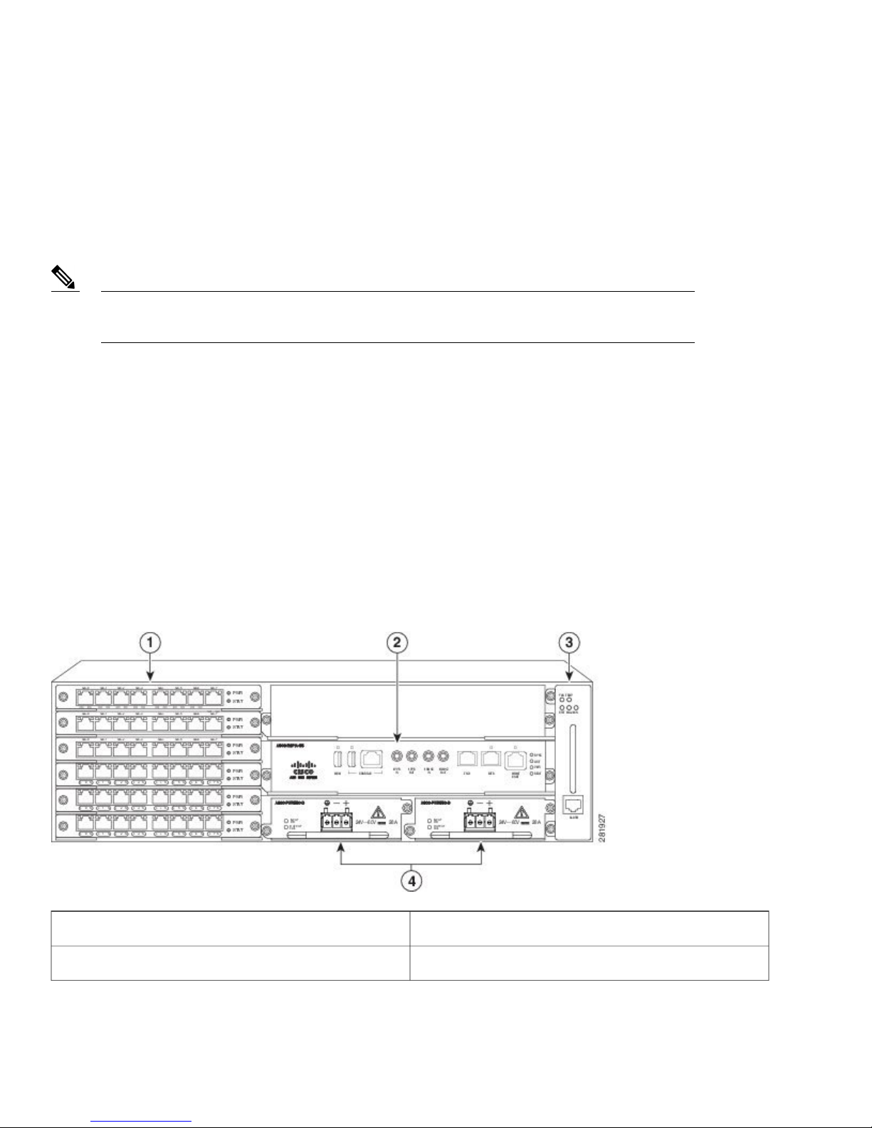
The figure below illustrates the router chassis design.
Figure 1: Router Chassis Design
2
Interface modules1
RSP unit (with active and standby RSP slots)2
Fan tray3
Redundant power units (two DC power units are shown)4
Power Supply Features
The Cisco ASR 903 Router support AC and DC power supplies. For more information about installing the Cisco ASR 903 Router
power supplies, see the Installing the Power Supply.
To estimate the required power supply, use the Cisco Power Calculator.
The power sections provide more information about the power supply:
Redundancy
The Cisco ASR 903 Router chassis includes a slot for an optional redundant power supply. The redundant power supply option
provides a second power supply to ensure that power to the chassis continues uninterrupted if one power supply fails or input power
on one line fails. Redundancy is supported either with identical power supplies or a combination of AC and DC power supply. The
Cisco ASR 903 Router supports current sharing between the power supplies.
A redundant power supply on the Cisco ASR 903 Router is recommended. Each power supply should be connected to separate
independent power sources to ensure that the router maintains power in the event of a power interruption caused by an electrical
failure, a wiring fault, or a tripped circuit breaker.
Caution
To comply with IEC 61850-3 (voltage interruptions), redundant power supplies with separately derived
power feeds are required.
Dying Gasp
The Cisco ASR 903 Router DC power supply supports the Dying Gasp feature, which allows the router to provide an input power
loss notification to the RSP so that the RSP can send appropriate SNMP traps or OAM messages and update log files on the router.
With the DC power supply, the router supports a minimum input power loss detection time of 2 milliseconds (DC) and continued
operation of at least 6 milliseconds (DC) after the notification.
Continued DC power supply operation may vary for voltages other than +24/-48V.Note
Dying Gasp is not supported on the ASR 900 RSP3 module for 1200W DC power supply.Note
Status LEDs
LEDs are also provided on each power supply to indicate the status of the input power and the health of the power supply. For more
information about the LEDs on the Cisco ASR 903 Router, see the Troubleshoting section in the Cisco ASR 903 and ASR 903U
Aggregation Services Router Hardware Installation Guide.
3

Fan Tray
The fan tray has the following hardware features:
It provides side-to-side forced air cooling
•
It provides redundant fans
•
It is field replaceable
•
It contains status LEDs
•
It contains an alarm port with four external alarm inputs
•
Dust Filter (A903-FAN-F)
The dust filter (see Figure 1-7 ) on the fan tray is a quadrafoam 45PPI filter which is 85 percent dust resistant. A dummy cover
(A903-FAN-F-B) secures the dust filter in the chassis. For installing the fan filter, see Installing the Dust Filter .
Use the pull tab provided to easily access the filter.Note
Air Plenum
Air Plenum or air baffle assembly (see Figure 3-7 ) is used change the air flow pattern of the unit. When the router is installed with
the plenum, the air flow pattern is changed from side-side to front-back. The air flow front-back pattern provides a rack installation
bay with a cool front zone and hot rear zone.
Note
The air plenum is available from GAW (www.GawTechnology.net). To order an air plenum, contact the Sales and Marketing support
staff at GAW.
When the air plenum and the fan filter are installed in the chassis, the system operating temperature is
limited to 55 degrees Celsius.
RSP Modules
The Cisco ASR 903 Router is designed to use up to two RSP modules to handle the data plane, network timing, and control plane
functionalities for the router. The RSP configuration allows you to use Cisco IOS software to control chassis management, redundancy,
external management, and system status indications on the router.
RSP features include:
Loading software onto processor-based interface modules
•
• Redundant RSP management—The RSP manages detection of RSPs, exchange of health and status information, role negotiation,
function for detection, health and status exchange, role negotiation
Packet processing
•
Traffic management, including buffering, queuing, and scheduling, Ethernet MAC functions
•
Network clocking functions including phase and time-of-day for BITS, 1 PPS, 10 MHz, and 1588 PTP clock references.
•
4

Storage of software images, system configuration, OBFL, SysLog
•
PTP packet processing including IEEE 1588-2008 for recovering network timing (frequency, phase, and time) from upstream
•
PTP clocks, for generating PTP frequency and phase references as inputs to the SETS, and for distributing them to downstream
PTP clocks
External management interfaces (RS232 console, management ENET, USB console, USB storage) and system status LED
•
indicators
Supported RSP Features
The RSP provides the following features on the Cisco router:
Centralized data plane, timing, and control plane functions for the system
•
High-level control of interface modules
•
Management functionalities for the router
•
Control plane (host) CPU and associated memory in which IOS-XE and platform control software runs
•
Nonvolatile memory for storage of software images, configurations, and system files
•
Enabling and monitoring the health and presence of fan trays, interface modules, and power supplies
•
Field replacement and hot-swap capabilities
•
RSP Redundancy
The Cisco ASR 903 Router chassis includes two RSP slots to allow for redundant RSPs. When the router uses redundant RSPs, one
RSP operates in the active mode and the other operates in the hot standby mode. Removal or failure of the active RSP results in an
automatic switchover to the standby RSP.
Note
If you are using redundant RSPs, both the RSPs must be of the same type because a mixed configuration
of two different RSP types is not supported.
GNSS Module (A900-CM-GNSS)
The GNSS module is present on the RSP3 modules. It is a pluggable module that allows direct interface with the external antenna.
Using a single GPS antenna input for both RSPs requires usage of external splitters.Note
To reduce the risk of fire, use only No. 26 AWG or larger telecommunication line cord. Statement 1023Warning
The GNSS module is not hot swappable.Note
5

GNSS Module RF Input Requirements
The GNSS module requires an active GPS/GNSS antenna with built-in Low-Noise Amplifier (LNA) for optimal performance.
•
The antenna LNA amplifies the received satellite signals for two purposes:
Compensation of losses on the cable
◦
Lifting the signal amplitude in the suitable range for the receiver frontend
◦
The Amplification required is 22dB gain + cable/connector loss + Splitter signal loss.
The recommended range of LNA gain (LNA gain minus all cable and connector losses) at the connector of the receiver module
is 22dB to 30dB with a minimum of 20dB and a maximum of 35dB.
GNSS module provides 5V to the active antenna through the same RF input.
•
Surge requirement:
•
GNSS modules have built-in ESD protections on all pins, including the RF-input pin. However, additional surge protection
◦
may be required if rooftop antennas are being connected, to meet the regulations and standards for lightning protection in
the countries where the end-product is installed.
A lightning protection must be mounted at the place where the antenna cable enters the building. The primary lightning
◦
protection must be capable of conducting all potentially dangerous electrical energy to PE (Protective Earth).
Surge arrestors should support DC-pass and suitable for the GPS frequency range (1.575GHz) with low attenuation.
◦
Antenna Sky visibility:
•
GPS signals can only be received on a direct line of sight between antenna and satellite. The antenna should see as much
◦
as possible from the total sky. For proper timing, minimum of four satellites should be locked.
Note
Use a passive splitter if more than one GNSS modules are fed from a single antenna.
•
Note
The splitter should have all the RF ports capable of DC-pass, if the antenna needs to feed power from
GNSS module.
The antenna terminal should be earthed at the building entrance in accordance with the
ANSI/NFPA 70, the National Electrical Code (NEC), in particular Section 820.93,
Grounding of Outer Conductive Shield of a Coaxial Cable.
Interface Modules
The Cisco ASR 903 Router interface modules are a field-replaceable units. In addition to the ports provided on an RSP, the Cisco
ASR 903 Router supports the following interface modules:
6
Note
For information about supported interface modules, see the Release Notes for the Cisco ASR 903 Series
Aggregation Services Router.
Installing the Router in a Rack
The following sections describe how to install the Cisco ASR 903 Router in a rack:
Installing the Chassis Brackets
The chassis is shipped with mounting brackets that can be installed on the front or rear of the chassis. To install the brackets on the
front of the chassis, perform these steps:
Procedure
Step 1
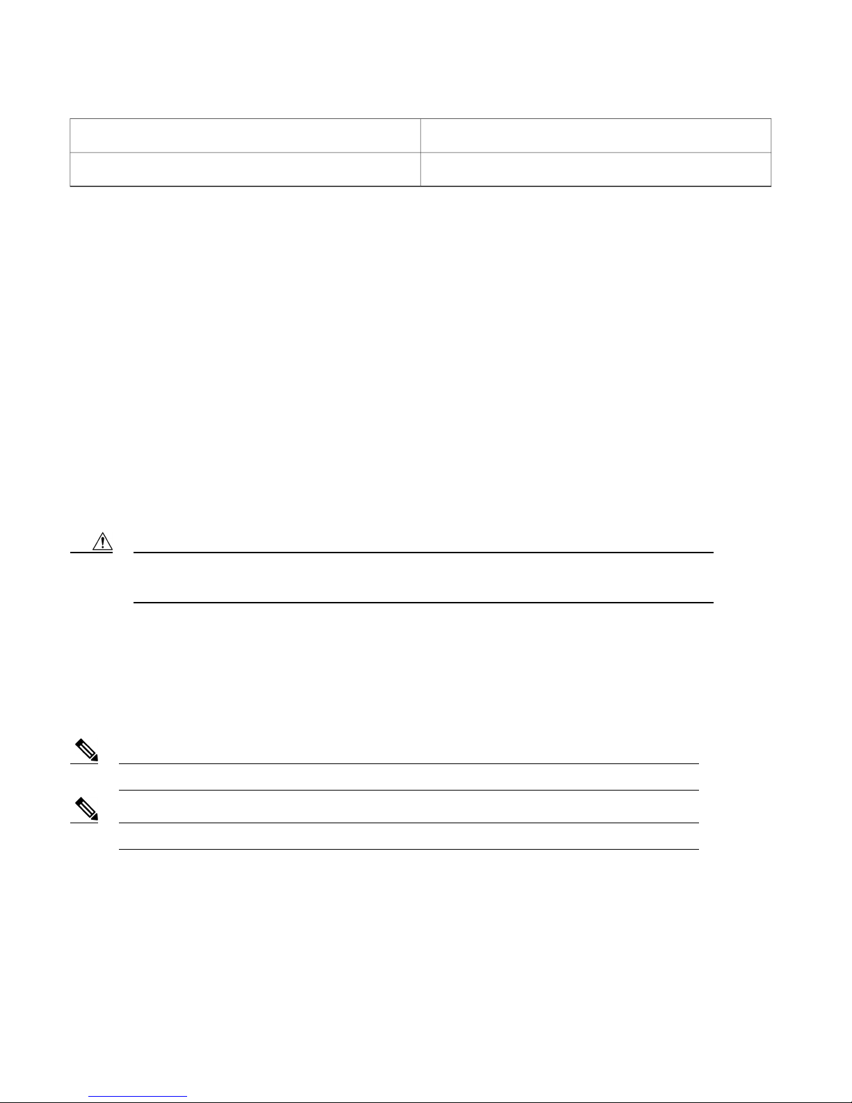
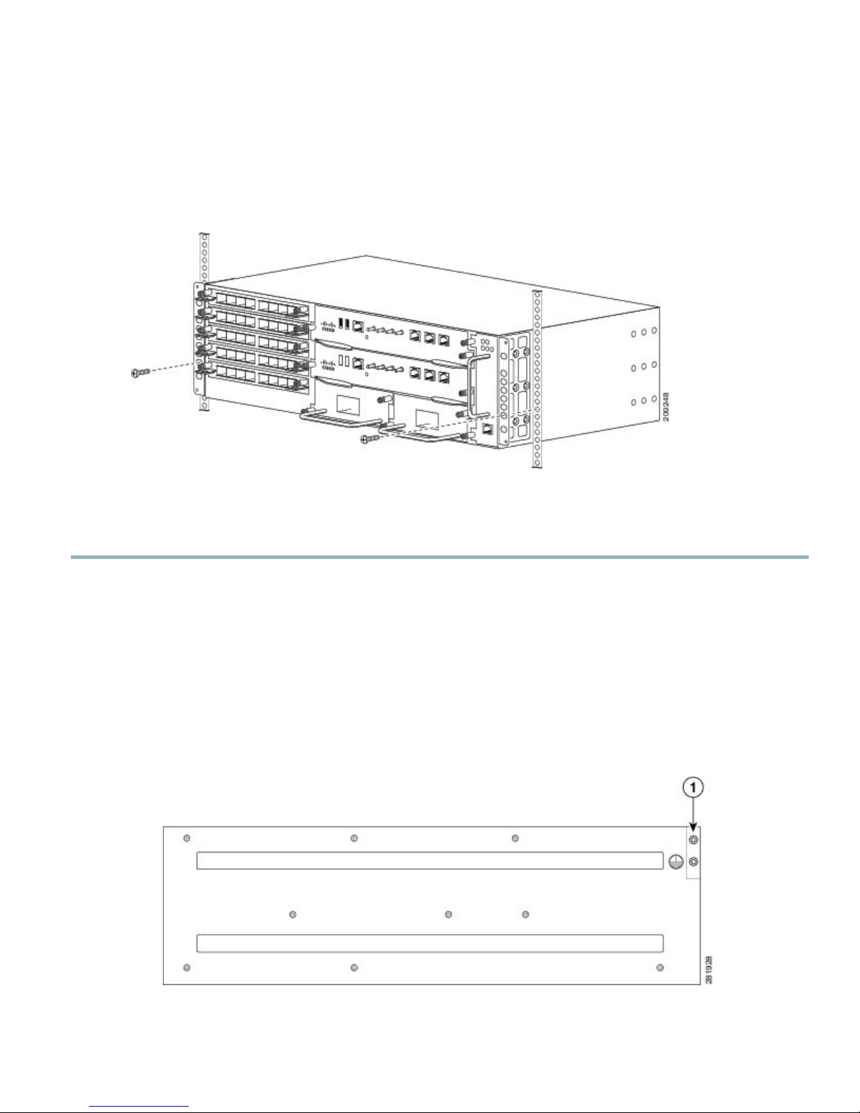
Remove the rack-mount brackets from the accessory kit and position them beside the router chassis. The figure below
hows how to attach the brackets on the Cisco ASR 903 Router for a 19-inch EIA rack.
Figure 2: Attaching Mounting Brackets for a 19-inch EIA Rack
7
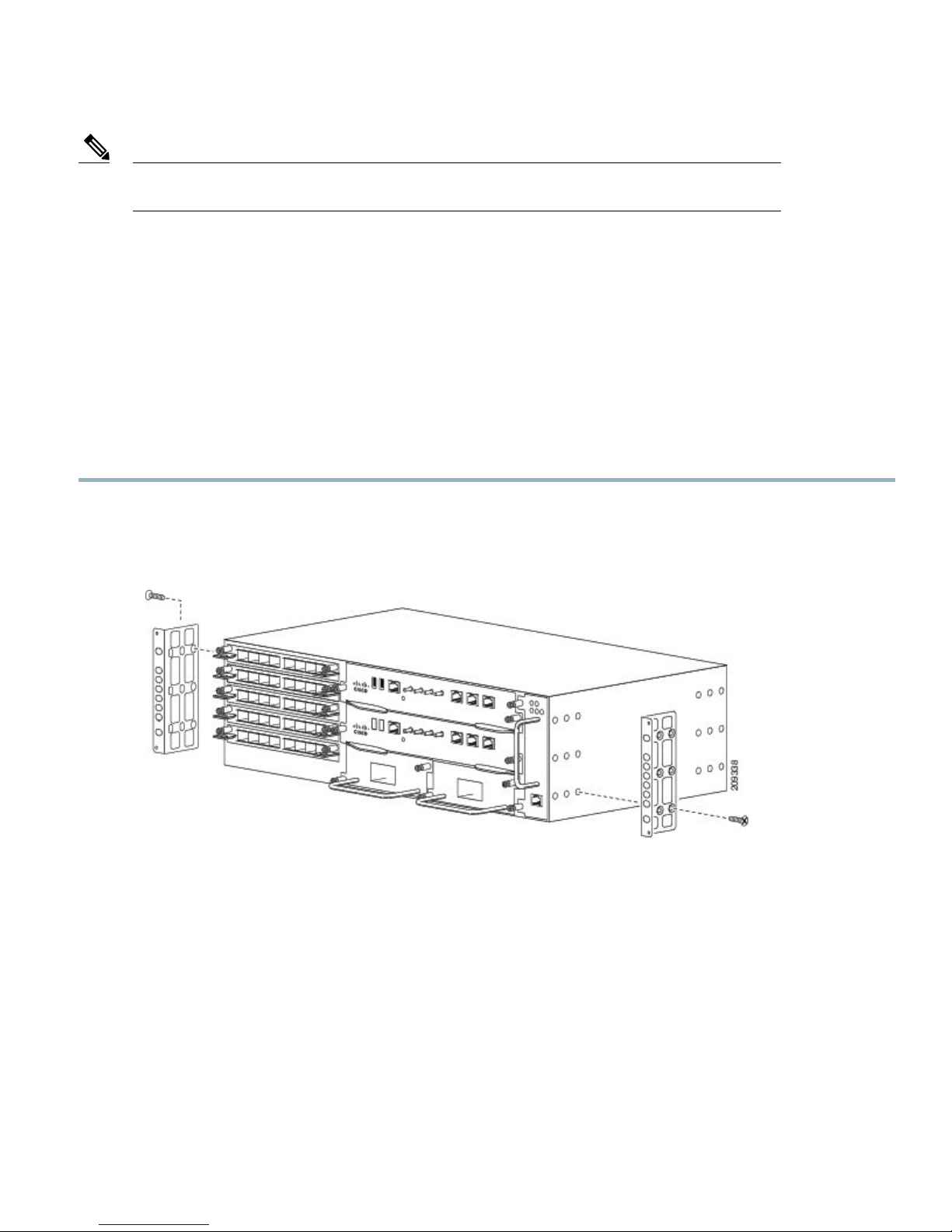
The figure below shows how to attach the brackets on the Cisco ASR 903 Router for a 300 mm ETSI cabinet.
Figure 3: Attaching Mounting Brackets for a 300 mm ETSI Cabinet
Step 2
Step 3
Position one of the brackets against the chassis side, and align the screw holes.
Secure the bracket to the chassis with the screws removed when performing Step 1 . The recommended maximum torque
is 28 in.-lb (3.16 N-m).
The A903-FAN-E fan tray with filter (A903-FAN-F) cannot be mounted using the mounting screws that are supported for
A903-FAN fan tray. This is not an issue with the FAN tray filter blank panel (A903-FAN-F-B). We recommend that you
use the short screws provided in the following rack mount kits to avoid interference of the air filter during rack mounting
and while replacing the fan tray (A903-FAN) with the fan tray (A903-FAN-E):
• 19” rack mount kit (A903-RCKMT-19IN)
ETSI rack mount kit (A903-RCKMT-ETSI)
•
What to Do Next
Repeat Step 2 and Step 3 for the other bracket.
Installing the Router Chassis in the Rack
To install the router chassis in the equipment rack, perform these steps:
Procedure
Step 1
8
Position the chassis in the rack as follows:
If the front of the chassis (front panel) is at the front of the rack, insert the rear of the chassis between the mounting
•
posts.
If the rear of the chassis is at the front of the rack, insert the front of the chassis between the mounting posts.
•
Step 2
Align the mounting holes in the bracket (and optional cable guide) with the mounting holes in the equipment rack.
Caution
Figure 4: Installing the Chassis in a 19-inch EIA Rack
Do not use interface module and power supply ejector handles to lift the chassis; using the handles to lift the
chassis can deform or damage the handles.
Step 3
Step 4
Install the 8 or 12 (4 or 6 per side) 12-24 x 3/4-inch or 10-32 x 3/4-inch screws through the holes in the bracket and into
the threaded holes in the equipment rack posts.
Use a tape measure and level to verify that the chassis is installed straight and level.
Installing the Chassis Ground Connection
Before you connect the power or turn on the power to the Cisco ASR 903 Router, you must provide an adequate chassis ground
(earth) connection to your router.
This section describes how to ground the Cisco ASR 903 Router chassis. The router provides two locations for attaching a 2-hole
grounding lug according to the rack-mounting brackets you use to install the router.
Figure 5: Attaching a Grounding Lug to the Rear of the Router in an EIA 19-inch Rack
9
 Loading...