

Page 1

Cisco ASR 903 Router Hardware Installation Guide
June 2013
Cisco Systems, Inc.
www.cisco.com
Cisco has more than 200 offices worldwide.
Addresses, phone numbers, and fax numbers
are listed on the Cisco website at
www.cisco.com/go/offices.
Text Part Number: OL-25178-04
Page 2

THE SPECIFICATIONS AND INFORMATION REGA RDING THE P RODUCTS IN THIS MANUAL ARE SUBJECT TO CHANGE W ITH OUT NOT ICE. A LL
STATEMENTS, INFORMATION, AND RECOMMENDATIONS IN THIS MANUAL ARE BELIEVED TO BE ACCURATE BUT ARE PRESENTED WITHOUT
WARRANTY OF ANY KIND, EXPRESS OR IMPLIED. USERS MUST TAKE FULL RESPONSIBILIT Y FOR THEIR APPLICATION OF ANY PRODUCTS.
THE SOFTWARE LICENSE AND LIMITED WARRA NTY FO R THE A CCOMPA NYING PRODUCT A RE SET FORTH IN T HE INFORM ATION P ACKET THAT
SHIPPED WITH THE PRODUCT AND ARE INCORPORATED HEREIN BY THIS REFERENCE. IF YOU ARE UNABLE TO LOCATE THE SOFTWARE LICENSE
OR LIMITED WARRANTY, CONTACT YOUR CISCO REPRESENTATIVE FOR A COPY.
NOTWITHSTANDING ANY OTHER WARRANTY HEREIN, ALL DO CUMENT FILES AND SOFTW ARE OF THESE SUPPL IERS ARE PROVIDED “AS IS” WITH
ALL FAULTS. CISCO AND THE ABOVE-NAMED SUPPLIERS DISCLAIM AL L WARRANTIES, EX PRESSED OR IMPLIED, INCLUDING, WITHO UT
LIMITATION, THOSE OF MERCHANTABILITY, FITNESS FOR A PARTICUL AR PURPOSE AND NON INFRINGEMENT OR ARISIN G FROM A COURSE OF
DEALING, USAGE, OR TRADE PRACTICE.
IN NO EVENT SHALL CISCO OR ITS SUPPLIERS BE LIABLE FOR ANY INDIRECT, SPECIAL, CONSEQUENTIAL, OR INCIDENTAL DAMAGES, INCLUDING,
WITHOUT LIMITATION, LOS T PROFITS OR LOSS OR DAMAGE TO DATA ARISIN G OUT OF THE US E OR INABILI TY TO USE THIS MA NUAL, EVEN I F CISCO
OR ITS SUPPLIERS HAVE BEEN ADVISED OF THE POSSIBILITY OF SU CH DAMA GES.
Cisco and the Cisco logo are trademarks or registered trademarks of Cisco and/or its affiliates in the U.S. and other countries. To view a list of Cisco trademarks, go to this
URL: www.cisco.com/go/trademarks. Third-p arty tr ademarks mentio ned are the p roperty o f their respective owners. The use of the word partner does not imply a partnership
relationship between Cisco and any other company. (1110R)
Any Internet Protocol (IP) addresses and phone numbers us ed in th is do cumen t are not in tended to be actual addres ses and phone numbers. Any ex ampl es, co mmand di sp lay
output, network topology diagrams, and other figures included in the document are shown for illustrative purposes only. Any use of actual IP addresses or phone numbers in
illustrative content is unintentional and coincidental.
Cisco ASR 903 Router Hardware Installation Guide
© 2012 Cisco Systems, Inc. All rights reserved.
Page 3

CONTENTS
About this Book ix
Document Revision History ix
Document Audience ix
Document Organization x
Document Conventions x
Obtaining Documentation and Submitting a Service Request xi
CHAPTER
1 Cisco ASR 903 Router Overview 1-1
Cisco ASR 903 Router Features 1-1
System Specifications 1-2
Power Supply Features 1-3
Redundancy 1-4
Dying Gasp 1-4
Status LEDs 1-4
DC Power Specifications 1-4
AC Power Specifications 1-5
Fan Tray 1-5
RSP Modules 1-6
Supported RSPs 1-7
Supported RSP Features 1-7
RSP Redundancy 1-7
Network Timing Interfaces 1-8
RSP Interfaces 1-8
Interface Modules 1-9
Gigabit Ethernet SFP Interface Module 1-9
Gigabit Ethernet RJ45 Interface Module 1-10
10 Gigabit Ethernet XFP Interface Module 1-11
T1/E1 Interface Module 1-13
OC-3 Interface Module 1-14
Temperature Sensor 1-15
Serial Number Label Location 1-15
OL-25178-04
Interface Numbering 1-15
Regulatory Compliance 1-16
Cisco ASR 903 Router Hardware Installation Guide
iii
Page 4

Contents
CHAPTER
2 Preparing for Installation 2-1
Safety Guidelines 2-1
Standard Warning Statements 2-2
Safety Guidelines for Personal Safety and Equipment Protection 2-3
Safety Precautions for Module Installation and Removal 2-3
Safety with Electricity 2-4
Power Supply Considerations 2-8
Preventing ESD Damage 2-8
Site Planning 2-9
General Precautions 2-9
Site Planning Checklist 2-9
Site Selection Guidelines 2-10
Environmental Requirements 2-10
Physical Characteristics 2-10
Air Flow Guidelines 2-11
Air Flow Guidelines for Enclosed Rack Installation 2-12
Floor Loading Considerations 2-12
Site Power Guidelines 2-12
Electrical Circuit Requirements 2-13
Site Cabling Guidelines 2-13
Asynchronous Terminal Connections 2-14
Interference Considerations 2-14
Rack-Mounting Guidelines 2-15
Precautions for Rack-Mounting 2-15
Rack Selection Guidelines 2-15
Equipment Rack Guidelines 2-16
Installation Checklist 2-18
Creating a Site Log 2-19
CHAPTER
iv
Receiving the Cisco ASR 903 Router 2-19
Chassis-Lifting Guidelines 2-20
Tools and Equipment 2-20
Unpacking and Verifying the Shipped Contents 2-21
3 Installing the Cisco ASR 903 Router 3-1
Prerequisites 3-1
Installing the Router in a Rack 3-1
Installing the Chassis Brackets 3-2
Installing the Router Chassis in the Rack 3-3
Attaching the Cable Management Brackets 3-4
Cisco ASR 903 Router Hardware Installation Guide
OL-25178-04
Page 5

Installing the Chassis Ground Connection 3-5
Installing the Fan Tray 3-8
Removing and Replacing the Fan Tray 3-8
RSP Installation 3-10
Installing an RSP Module 3-11
Removing an RSP Module 3-12
Hot-Swapping an RSP Module 3-13
Interface Module Installation 3-14
Installing an Interface Module 3-14
Removing an Interface Module 3-15
Hot-Swapping an Interface Module 3-15
Installing the Power Supply 3-17
Preventing Power Loss 3-17
Power Connection Guidelines 3-18
Guidelines for DC-Powered Systems 3-18
Guidelines for AC-Powered Systems 3-18
Installing the DC Power Supply 3-19
Installing the DC Power Supply Module 3-19
Installing the Terminal Block 3-20
Activating the DC Power Supply 3-23
Removing and Replacing the DC Power Supply 3-24
Installing the AC power Supply 3-25
Installing the AC Power Supply Module 3-25
Activating the AC Power Supply 3-26
Removing and Replacing the AC Power Supply 3-26
Contents
OL-25178-04
Connecting the Cisco ASR 903 Router to the Network 3-27
Connecting Console Cables 3-27
Connecting to the Serial Port using Microsoft Windows 3-28
Connecting to the Console Port using Mac OS X 3-30
Connecting to the Console Port using Linux 3-30
Installing the Cisco Microsoft Windows USB Device Driver 3-31
Uninstalling the Cisco Microsoft Windows USB Driver 3-32
Connecting to the Auxiliary Port 3-33
Connecting a Management Ethernet Cable 3-35
Installing and Removing SFP and XFP Mo du les 3-35
Connecting a USB Flash Device 3-35
Removing a USB Flash Device 3-36
Connecting Timing Cables 3-36
Connecting Cables to the BITS Interface 3-36
Cisco ASR 903 Router Hardware Installation Guide
v
Page 6

Contents
Connecting Cables to a GPS Interface 3-38
Connecting Ethernet Cables 3-39
Connecting Cables to SFP Modules 3-40
Connecting T1/E1 cables 3-40
Installing the Cable Connector 3-40
RJ45 Cable Pinouts 3-41
Connecting Cables to the Patch Panel 3-41
Recommended Patch Panel 3-42
Connecting the Fan Tray Alarm Port 3-42
Connector and Cable Specifications 3-43
CHAPTER
CHAPTER
4 Cisco ASR 903 Router Initial Configuration 4-1
Checking Conditions Prior to System Startup 4-1
Powering Up the Cisco ASR 903 Router 4-2
Verifying the Front Panel LEDs 4-5
Verifying the Hardware Configuration 4-5
Checking Hardware and Software Compatibility 4-5
Configuring the Cisco ASR 903 Router at Startup 4-5
Using the Console Interface 4-6
Configuring Global Parameters 4-6
Checking the Running Configuration Settings 4-7
Saving the Running Configuration to NVRAM 4-7
Safely Powering Off the Cisco ASR 903 Router 4-8
5 Troubleshooting 5-1
Pinouts 5-1
BITS Port Pinout 5-1
GPS Port Pinout 5-2
Time of Day Port Pinout 5-2
Alarm Port Pinout 5-3
Console/Aux RJ45 RS232 Serial Po rt Pinout 5-3
T1/E1 Port Pinout 5-4
Management Ethernet Port Pinout 5-5
USB Console Port Pinout 5-6
USB Flash/MEM Port Pinout 5-6
Fiber-Optic Specifications 5-6
vi
LED Summary 5-7
RSP LEDs 5-7
Interface Module LEDs 5-8
Cisco ASR 903 Router Hardware Installation Guide
OL-25178-04
Page 7

OC-3 Interface Module LEDs 5-9
T1/E1 Interface Module LEDs 5-9
Power Supply LEDs 5-10
Fan Tray LEDs 5-10
Alarm Conditions 5-11
Contents
CHAPTER
I
NDEX
A Site Log A-1
OL-25178-04
Cisco ASR 903 Router Hardware Installation Guide
vii
Page 8

Contents
viii
Cisco ASR 903 Router Hardware Installation Guide
OL-25178-04
Page 9

About this Book
The preface describes the revision history, audience, organization, and conventions of Cisco ASR 903
Ro uter Ha rd wa re In s ta l la tion Gu i de. It also lists sources for obtaining additional information and
technical assistance from Cisco Systems.
• Document Revision History, page ix
• Document Audience, page ix
• Document Organization, page x
• Document Conventions, page x
• Obtaining Documentation and Submitting a Service Request, page xi
Document Revision History
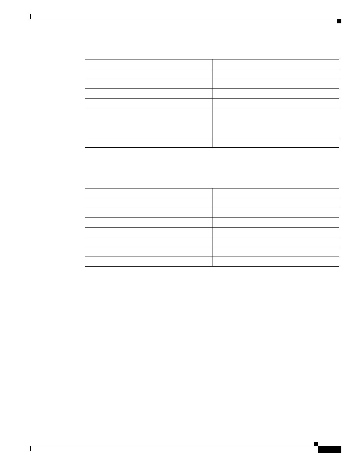
The following table lists the major changes made to this document for each release.
Revision Date Change Summary
OL-25178-04 3 June 2013 Updated supported SFPs for IOS XE Release 3.9. 1
OL-25178-03 3 April 2013 Updated supported SFPs for IOS XE Release 3.9.
OL-25178-03 29 November 2012 Updated supported SFPs for IOS XE Release 3.8.
OL-25178-03 23 August 2012 Added material for AC power supply, chassis air flow
OL-25178-02 30 March 2012 Updated supported SFPs for IOS XE Release 3.6.
OL-25178-02 24 February 2012 Added power draw and installation torque values.
OL-25178-01 16 December 2011 First release published.
information, and NEBS certification.
Document Audience
This guide is intended for users who are responsible for installing the Cisco ASR 9 03 Series Aggregation
Services Router. It is intended for users who may not be familiar with the initial configuration and
troubleshooting tasks, the relationship among tasks, or the Cisco IOS software commands necessary to
perform particular tasks.
OL-25178-04
Cisco ASR 903 Router Hardware Installation Guide
-ix
Page 10
Document Organization
This guide includes the following chapters and appendix:
Title Description
Chapter 1, “Cisco ASR 903 Router
Overview”
Chapter 2, “Preparing for
Installation”
Chapter 3, “Installing the Cisco ASR
903 Router”
Chapter 4, “Cisco ASR 903 Router
Initial Configuration”
Chapter 5, “Troubleshooting” This chapter provides LED and pinout
Appendix A, “Site Log” This provides a site log for tracking the
Chapter
This chapter provides an overview of the
Cisco ASR 903 Router.
This chapter provides site preparation guidelines
for installing the Cisco ASR 903 Router.
This chapter describes the Cisco ASR 903 Router
and how to install it.
This chapter describes how to start the
Cisco ASR 903 Router and create an initial
system configuration.
information for troubleshooting purposes.
installation and maintenance activities of the
router.
Document Conventions
This document uses the following conventions:
Convention Indication
bold font Commands and keywords and user-entered text appear in bold font.
italic font Document titles, new or emphasized terms, and arg uments for which you supply
[ ] Elements in square brackets are optional.
{x | y | z } Required alternative keywords are grouped in braces and separated by
[ x | y | z ] Optional alternative keywords are grouped in brackets and separated by
string A nonquoted set of characters. Do not use quotation marks around the string or
courier font Terminal sessions and information the system displays appear in courier font.
< > Nonprinting characters such as passwords are in angle brackets.
[ ] Default responses to system prompts are in square brackets.
!, # An exclamation point (!) or a pound sign (#) at the beginning of a line of code
values are in italic font.
vertical bars.
vertical bars.
the string will include the quotation marks.
indicates a comment line.
-x
Note Means reader take note.
Cisco ASR 903 Router Hardware Installation Guide
OL-25178-04
Page 11
Chapter
Tip Means the following information will help you solve a problem.
Caution Means reader be careful. In this situation, you might perform an action that could result in equipment
damage or loss of data.
Timesaver Means the described action saves time. You can save time by performing the action described in
the paragraph.
Warning
Means reader be warned. In this situation, you might perform an action that could result in
bodily injury.
Obtaining Documentation and Submitting a Service Request
For information on obtaining documentation, submitting a service request, and gathering additional
information, see the monthly What’s New in Cisco Product Documentation, which also lists all new and
revised Cisco technical documentation, at:
http://www.cisco.com/en/US/docs/general/whatsnew/whatsnew.html
Subscribe to the What’s New in Cisco Product Documentation as an RSS feed and set content to be
delivered directly to your desktop using a reader application. The RSS feeds are a free service. Cisco currently
supports RSS Version 2.0.
OL-25178-04
Cisco ASR 903 Router Hardware Installation Guide
-xi
Page 12

Chapter
-xii
Cisco ASR 903 Router Hardware Installation Guide
OL-25178-04
Page 13

Cisco ASR 903 Router Overview
The Cisco ASR 903 Router is a fully-featured aggregation platform designed for the cost-effective
delivery of converged mobile and business services. With shallow depth, low power consumption, and
an extended temperature range, this compact 3-rack-unit (RU) router provides high service scale, full
redundancy, and flexible hardware configuration.
The Cisco ASR 903 Router expands the Cisco service provider product portfolio by pro viding a rich and
scalable feature set of Lay er 2 VPN (L2VPN) and Layer 3 VPN (L3VPN) services in a compact package .
It also supports a variety of software features, in cluding Carrier Ethernet fe atures, Timing over Packet,
and pseudowire.
The Cisco ASR 903 Router is positioned as a pre-aggregation router in IP RAN (GSM, UMTS, iMAX,
CDMA, and LTE) networks or an aggregation router in Carrier Ethernet networks.
Cisco ASR 903 Router Features
CHAPTER
1
The Cisco ASR 903 Router has the following hardware features:
• 3-RU modular chassis designed for installation in a 300 mm European Telecommunications
Standards Institute (ETSI) cabinet
• Dedicated slots in the chassis that support the following:
–
Up to six interface modules
–
Up to two Route Switch Processors (RSP)
–
Up to two DC power supply units
–
One fan tray
• Network frequency, phase, and time inputs and outputs for network interfaces (SyncE and TDM),
BITS, 1 PPS or 10 MHz and Timing over Packet (IEEE 1588-2008)
• Adjustable front and rear rail mounting locations
• Front panel access to power supplies, fan tray, RSPs, and interface modules
• Online insertion and removal (OIR) of RSP, interface modules, power supplies, and fan tray
• Discrete status LEDs on power supply, interface module, RSP, and fan tray units
• Four alarm dry contact inputs (either normally open or normally closed)
• Environmental monitoring and reporting functions
• LED indicators for critical, major, and minor alarms
OL-25178-04
Cisco ASR 903 Router Hardware Installation Guide
1-1
Page 14
Cisco ASR 903 Router Features
• Side-to-side forced air cooling
• Temperature range of -40 to 149 degrees F (-40 to 65 degrees C) with DC power supply
• Temperature range of -32 to 104 degrees F (0 to 40 degrees C) with AC power supply
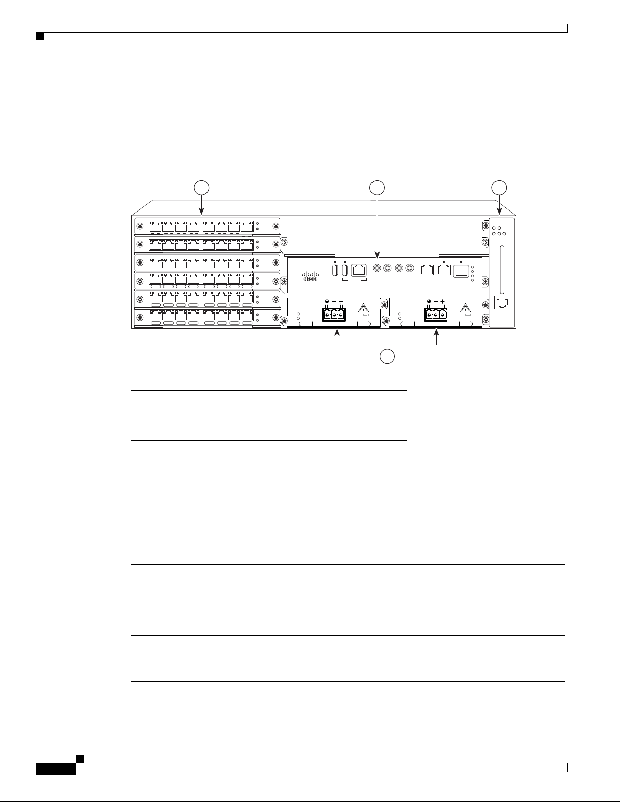
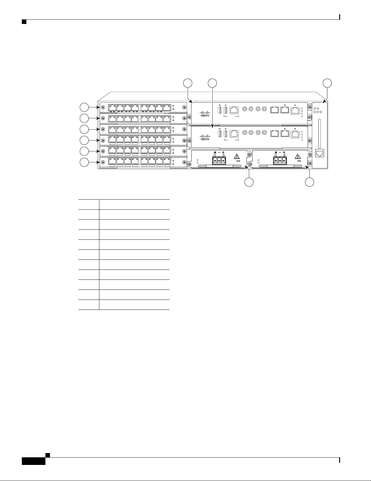
Figure 1-1 illustrates the Cisco ASR 903 Router chassis design.
Figure 1-1 Cisco ASR 903 Router Chassis Design
Chapter 1 Cisco ASR 903 Router Overview
1 32
GE-0 GE-1 GE-2 GE-3 GE-4 GE-5 GE-6 GE-7
GE-0 GE-1 GE-2 GE-3 GE-4 GE-5 GE-6 GE-7
GE-0 GE-1 GE-2 GE-3 GE-4 GE-5 GE-6 GE-7
L 0 S L 1 S L 2 S L 3 S L 4 S L 5 S L 6 S L 7 S
L 0 S L 1 S L 2 S L 3 S L 4 S L 5 S L 6 S L 7 S
L 0 S L 1 S L 2 S L 3 S L 4 S L 5 S L 6 S L 7 S
1 Interface module s
2 RSP unit
3Fan tray
4 Redundant power units (two DC power units are sho wn)
System Specifications
PWR
STAT
PWR
STAT
PWR
STAT
PWR
STAT
PWR
STAT
PWR
STAT
RUDY RSP
INPUT
OK
OUTPUT
FAIL
CONSOLE
24V—60V 28A
1PPSIN1PPS
MEM TOD BITS MGMT
1OMHZ
1OMHZ
OUT
OUT
IN
INPUT
OK
OUTPUT
FAIL
24V—60V 28A
ENET
FAN TEM P
CRIT MAJ MIN
SYNC
ACT
PWR
STAT
ALARM
281927
4
1-2
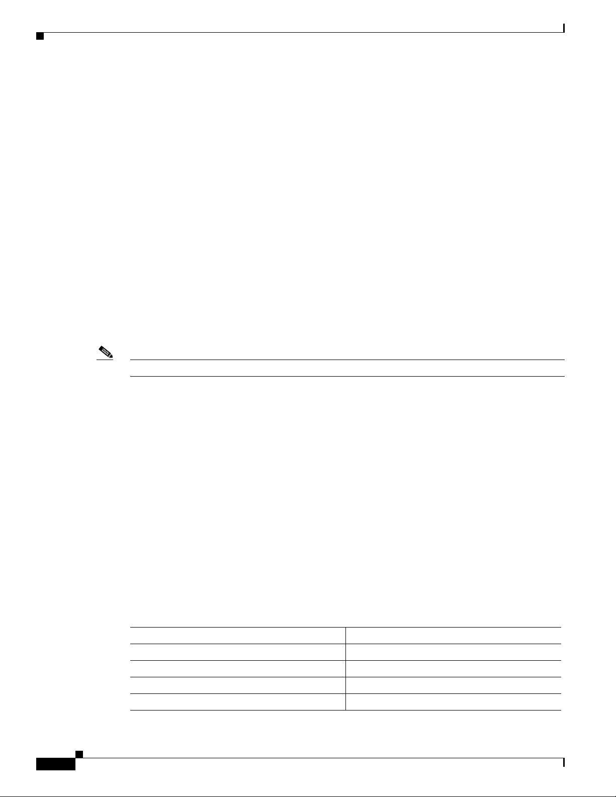
Table 1-1 summarizes the system specifications and environmental requirements for the
Cisco ASR 903 Router.
Table 1-1 Cisco ASR 903 Router System Specifications
Dimensions (Height x Width x Depth) 5.22 in. x17.44 in. x 10.565 in.
(132.588 x 442.976 x 268.351 mm)
Note This measurement includes handles from
the power supply, fan tray, and interface
modules installed in the chassis.
Weight 27.117 pounds (12.3 kg)
Note This weight includes a redundant RSP and
power supply.
Cisco ASR 903 Router Hardware Installation Guide
OL-25178-04
Page 15

Chapter 1 Cisco ASR 903 Router Overview
Table 1-1 Cisco ASR 903 Router System Specifications
Operating Temperature The Cisco ASR 903 Router supports the
Nonoperating Temperature -40 to 158 degrees F (-40 to + 70 degrees C)
Operating Humidity 5—95% operating noncondensing relative
Operating Altitude Up to 4000 m operating altitude at up to 104
Nonoperating Altitude 4570 m storage altitude
Operating Vibration 0.41 Grms, 3 to 200 Hz/100 minutes per axis
Cisco ASR 903 Router Features
following temperature ranges with the DC power
supply:
• -60–4000 meters: -40 to 104 degrees F
(-40 to + 40 degrees C)
• -60–1800 meters: -40 to 149 degrees F
(-40 to + 65 degrees C)
The Cisco ASR 903 Router supports the
following temperature ranges with the AC power
supply:
• -60—4000 meters:32 to 104 degrees F
(0 to 40 degrees C)
• -60—1800 meters: 23 to 140 degrees F
(-5 to 60 degrees C)
storage temperature
humidity
Reviewers, is this number different for the AC
PS? (SFS lists 10-90%)
degrees F (40 degrees C) temperature
Nonoperating Vibration Random: 1.15 gRMS 3 to 200 Hz, 30 minutes/axis
Operating Acoustics < 55 dBa @ 27 degrees C
Power Supply Features
The Cisco ASR 903 Router support AC and DC power supplies. For more information about installing
the Cisco ASR 903 Router power supplies, see the Installing the Power Supply, page 3-17 section. The
power sections provide more information about the power supply:
• Redundancy, page 1-4
• Dying Gasp, page 1-4
• Status LEDs, page 1-4
• DC Power Specifications, page 1-4
Sine: 10 to 500 Hz. @ 0.15 G peak 5 sweep
cycles/axis
GR-63-CORE earthquake resistance, Zone 4,
shelf-level
Sine: 10 to 500 Hz @ 0.8 G peak / 5 sweep
cycles/axis
OL-25178-04
Cisco ASR 903 Router Hardware Installation Guide
1-3
Page 16
Cisco ASR 903 Router Features
Redundancy
Dying Gasp
Chapter 1 Cisco ASR 903 Router Overview
• AC Power Specifications, page 1-5
The Cisco ASR 903 Router chassis includes a slot for an optional redundant power supply. The
redundant power supply option provides a second, identical power supply to ensure that power to the
chassis continues uninterrupted if one p ower supply fails or input power on one line fail s. The
Cisco ASR 903 Router supports current sharing between the power supplies.
If you install a redundant po wer supply on the Cisco ASR 903 Router, we recommend that you connect
each power supply to a separate input po wer source in or der to ensure that the router mai ntains po wer in
the event of a power interruption caused by an electrical failure, a wiring fault, or a tripped circuit
breaker.
The Cisco ASR 903 Router DC power supply supports the Dying Gasp feature, which allows the router
to provide an input power loss notification to the RSP so that the RSP can send appropriate SNMP traps
or OAM messages and update log files on the router. With the DC power supply, the router supports a
minimum input power loss detection time of 2 milliseconds (DC) and continued operation of at least 6
milliseconds (DC) after the notification.
Note Continued DC power supply operation may vary for voltages other than +24/-48V.
Status LEDs
LEDs are also provided on each power supply to indicate the status of the input power and the health of
the power supply. For more information about the LEDs on the Cisco ASR 903 Router, see Chapter 5,
“Troubleshooting.”
DC Power Specifications
The Cisco ASR 903 Router uses a +24/-48 Volts Direct Current (VDC) (-19 to -72 VDC supply
tolerance) power supply. The power supply provides 550 W output power for system 12 V power. The
power supply is field replaceable, hot-swappable, and operates separately from the fan tray.
The power supply uses a three-position terminal block-style connector with labeled connections for
ground, -24/48 V, and +24/48 V . The po wer supply contains a front panel with mounting screws, a handle
for insertion and removal, and two status LEDs. No ON/OFF switch is provided.
Table 1-2 summarizes the input power specifications for the Cisco ASR 903 Router DC power supply.
Table 1-2 DC Power Supply Specifications
Part number A900-PWR550-D
Input power specification +24/-48 VDC
Input voltage -48/-60 VDC
Minimum input voltage -19.2 VDC
Maximum input voltage -72 VDC
1-4
Cisco ASR 903 Router Hardware Installation Guide
OL-25178-04
Page 17
Chapter 1 Cisco ASR 903 Router Overview
Table 1-2 DC Power Supply Specifications
Part number A900-PWR550-D
Input power specification +24/-48 VDC
Input voltage -48/-60 VDC
Minimum output voltage -36/18 VDC
Maximum output voltage -72/36 VDC
Wire gauge for DC input power connections 12 AWG minimum for -48/-60 VDC.
Power dissipation 600 W
AC Power Specifications
Table 1-3 AC Power Supply Specifications
Cisco ASR 903 Router Features
8 AWG minimum for 24 VDC.
Connector accepts 8 AWG maximum.
Fan Tray
Part number A900-PWR550-A
Input power specification 115VAC/ 230VAC
Input voltage 85/264 VAC
Minimum input voltage 85 VAC
Maximum input voltage 264 VAC
Minimum output voltage 12V
Maximum output voltage 12.4V
Power dissipation 600 W
The Cisco ASR 903 Router uses a modular fan tray that is separate from the power supply. The fan tray
contains twelve fans and provides sufficient capacity to maintain operation indefinitely in the event of
an individual fan failure.
The fan tray has the following hardware features:
• It provides side-to-side forced air cooling
• It provides redundant fans
• It is field replaceable
• It contains status LEDs
• It contains an alarm port with four external alarm inputs
OL-25178-04
Cisco ASR 903 Router Hardware Installation Guide
1-5
Page 18

Cisco ASR 903 Router Features
281933
ALARM
FAN TEMP
CRIT MAJ MIN
Figure 1-2 shows the fan tray.
Figure 1-2 Cisco ASR 903 Router Fan Tray
Chapter 1 Cisco ASR 903 Router Overview
RSP Modules
For more information about air flo w gui delines, see Air Flo w Guidelines, page 2-11. For instructions on
how to install the fan tray, see Installing the Fan Tray, page 3-8. For a summary of the LEDs on the fan
tray, see “LED Summary” section on page 5-7.
The Cisco ASR 903 Router is designed to use up to two RSP modules to handle the data plane, network
timing, and control plane functionalities for the router. The RSP configuration allows you to use Cisco
IOS software to control chassis management, red undancy, external management, and system status
indications on the router.
The following sections describe the Cisco ASR 903 Router RSP:
• Supported RSP Features, page 1-7
• RSP Redundancy, page 1-7
• Network Timing Interfaces, page 1-8
• RSP Interfaces, page 1-8
RSP features include:
• Loading software onto processor-based interface modules
• Redundant RSP management—The RSP manages detection of RSPs, exchange of health and status
information, role negotiation, function for detection, health and status exchange, role negotiation
• Packet processing
1-6
Cisco ASR 903 Router Hardware Installation Guide
OL-25178-04
Page 19

Chapter 1 Cisco ASR 903 Router Overview
• Traffic management, including buffering, queuing, and scheduling, Ethernet MAC functions
• Network clocking functions including phase and time-of-day for BITS, 1 PPS, 10 MHz, and 1588
PTP clock references.
• Storage of software images, system configuration, OBFL, SysLog
• PTP packet processing including IEEE 1588-2008 for reco ver ing network t iming (frequenc y, phase,
and time) from upstream PTP clocks, for generating PTP frequency and phase references as inputs
to the SETS, and for distributing them to downstream PTP clocks
• External management interfaces (RS232 console, management ENET, USB console, USB storage)
and system status LED indicators
Supported RSPs
The Cisco ASR 903 Router supports the following RSPs:
• A900-RSP1A-55—Provides 2 GB of SDRAM, 5 Mb of TCAM memory, 3-Mb buffer table,
576-Mb forwarding memory, and 1,536-Mb packet buffer memory.
• A900-RSP1B-55—Provides 4 GB of SDRAM, 20 Mb of TCAM memory, 144-Mb buffer table,
1152-Mb forwarding memory, and 1,536-Mb packet buffer memory.
Cisco ASR 903 Router Features
Note The supported RSPs have different memory capacities, but they have the same interfaces and
functionality.
Supported RSP Features
The RSP provides the following features on the Cisco router:
• Centralized data plane, timing, and control plane functions for the system
• High-level control of interface modules
• Management functionalities for the router
• Control plane (host) CPU and associated memory in which IOS-XE and platform control software
runs
• Nonvolatile memory for storage of software images, configurations, and system files
• Enabling and monitoring the health and presence of fan trays, interface modules, and po wer supplies
• Field replacement and hot-swap capabilities
RSP Redundancy
The Cisco ASR 903 Router chassis includes two RSP slots to allow for redundant RSPs. When the router
uses redundant RSPs, one RSP operates in the active mode and the other operates in the hot standby
mode. Removal or failure of the active RSP results in an automatic switchover to the standby RSP.
OL-25178-04
Note If you are using redundant RSPs, both the RSPs must be of the same type because a mixed conf iguration
of two different RSP types is not supported.
Cisco ASR 903 Router Hardware Installation Guide
1-7
Page 20
Cisco ASR 903 Router Features
Network Timing Interfaces
The RSP supports the following network timing interfaces:
• BITS input/output port—RJ48 jack
• 1 PPS input and output—Mini coax connectors
• 2.048 or 10 MHz input and output—Mini coax connectors
• Time of Day (ToD) or 1 PPS input or output port—Shielded RJ45 jack
Network timing interfaces support redundancy in a redundant RSP configuration. Network timing
interfaces on a redundant RSP remain in operation while the RSP is in hot standby mode.
RSP Interfaces
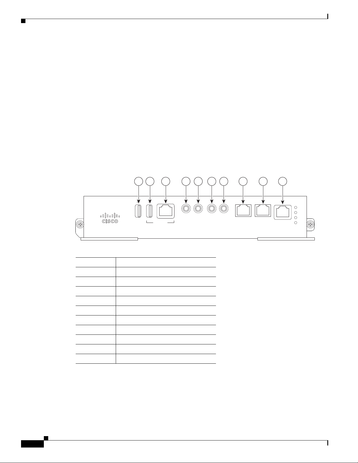
Figure 1-3 summarizes the interfaces on the RSP module.
Figure 1-3 RSP Interfaces Summary
Chapter 1 Cisco ASR 903 Router Overview
31 2 4 5 6 7 8 9 10
RUDY RSP
MEM TOD BITS MGMT
CONSOLE
1PPSIN1PPS
Label Interface
1 USB memory port
2 USB console port
3 Console port
4 1 PPS input timing port
5 1 PPS output timing port
6 10 MHz input timing port
7 10 MHz output timing port
8 Time of Day (ToD) timing port
9 BITS timing port
10 Ethernet management port
OUT
1OMHZ
IN
1OMHZ
OUT
ENET
SYNC
ACT
PWR
STAT
281931
1-8
For more information about installing the RSP, see RSP Installation, page 3-10. For more information
about the RSP LEDs, see RSP LEDs, page 5-7.
Cisco ASR 903 Router Hardware Installation Guide
OL-25178-04
Page 21
Chapter 1 Cisco ASR 903 Router Overview
282440
Interface Modules
In addition to the ports provided on an RSP, the Cisco ASR 903 Router supports the following interface
modules:
• Gigabit Ethernet SFP Interface Module, page 1-9
• Gigabit Ethernet RJ45 Interface Module, page 1-10
• 10 Gigabit Ethernet XFP Interface Module, page 1-11
• T1/E1 Interface Module, page 1-13
• OC-3 Interface Module, page 1-14
Note For information about supported interface modu les, see the Rel eas e Notes for the Cisco ASR 903 Series
Aggregation Services Router.
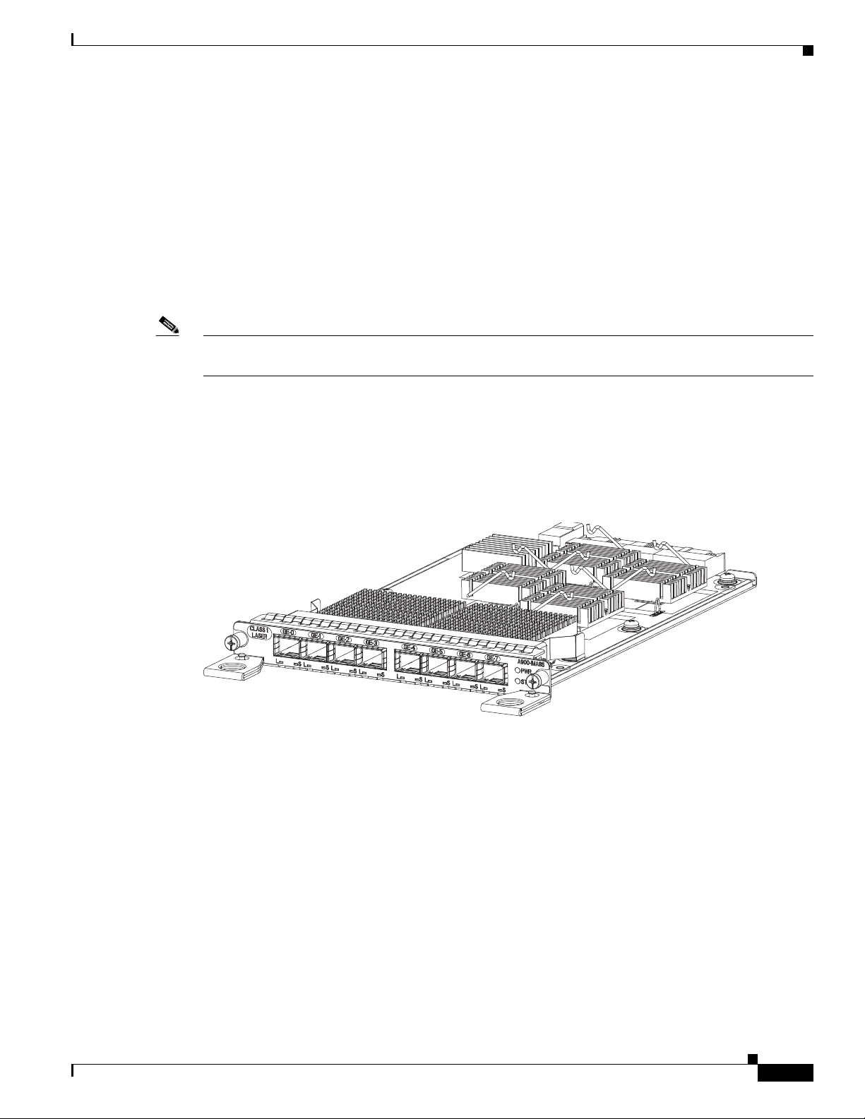
Gigabit Ethernet SFP Interface Module
The Gigabit Ethernet Small Form-Factor Pluggable (SFP) interface module provides eight Gigabit
Ethernet SFP modules. Figure 1-4 shows the 8 x 1 GE Gigabit Ethernet SFP interface module.
Cisco ASR 903 Router Features
Supported SFP Modules
Figure 1-4 8 x 1 GE Gigabit Ethernet SFP Interface Module
The Gigabit Ethernet SFP interface module supports the following SFP modules:
• GLC-BX-D
• GLC-BX-U
• GLC-EX-SMD
• GLC-FE-100BX-D
• GLC-FE-100BX-U
• GLC-FE-100EX
OL-25178-04
• GLC-FE-100FX
• GLC-FE-100FX-RGD
Cisco ASR 903 Router Hardware Installation Guide
1-9
Page 22
Cisco ASR 903 Router Features
282439
• GLC-FE-100LX
• GLC-FE-100LX-RGD
• GLC-FE-100ZX
• GLC-LH-SMD
• GLC-LH-SM-RGD
• GLC-SX-MMD
• GLC-SX-MM-RGD
• GLC-TE
• GLC-ZX-SMD
• GLC-ZX-SM-RGD
• SFP-GE-L
• SFP-GE-S
• SFP-GE-T
• SFP-GE-Z
Chapter 1 Cisco ASR 903 Router Overview
For more information about installing a SFP Gigabit Ethernet module, see the “Interface Module
Installation” section on page 3-14.
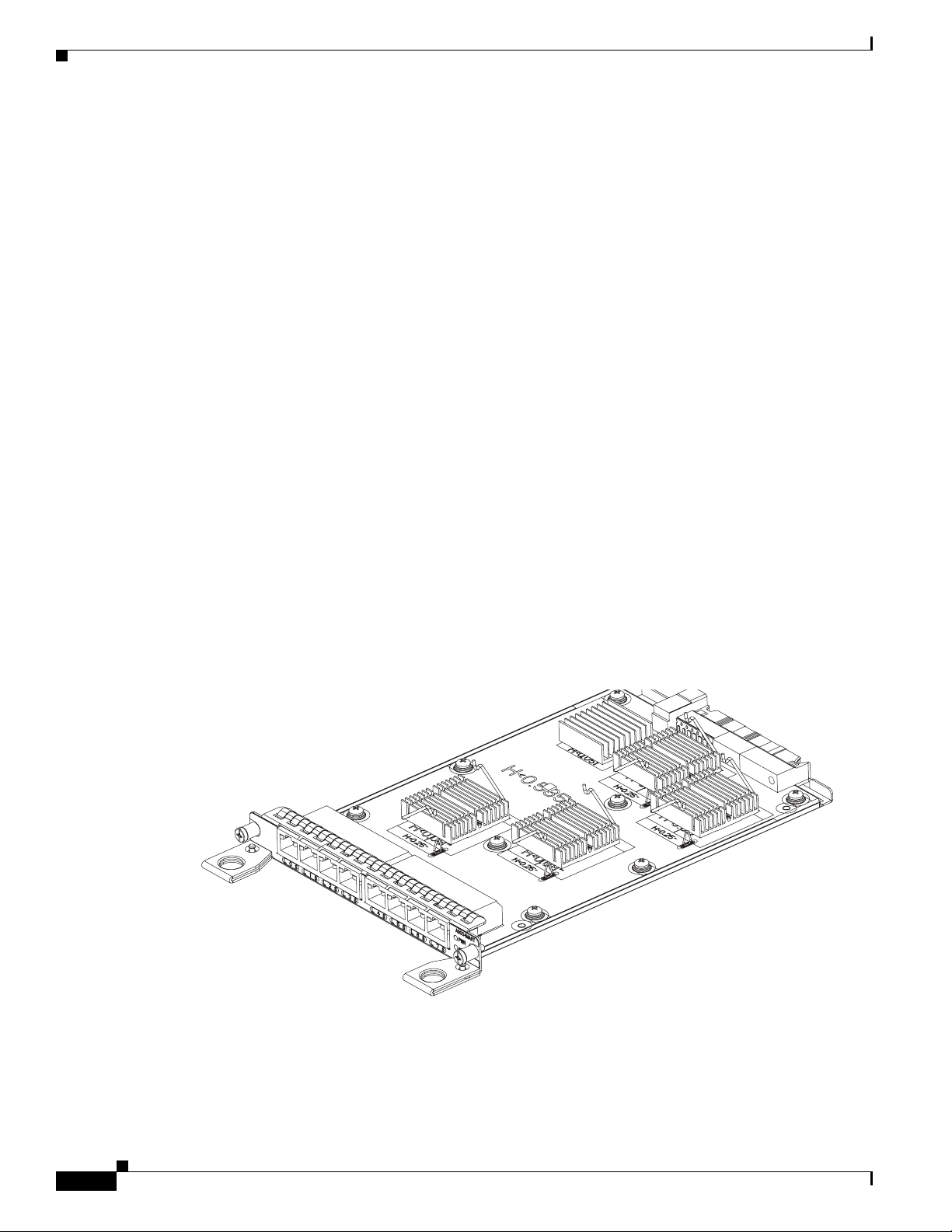
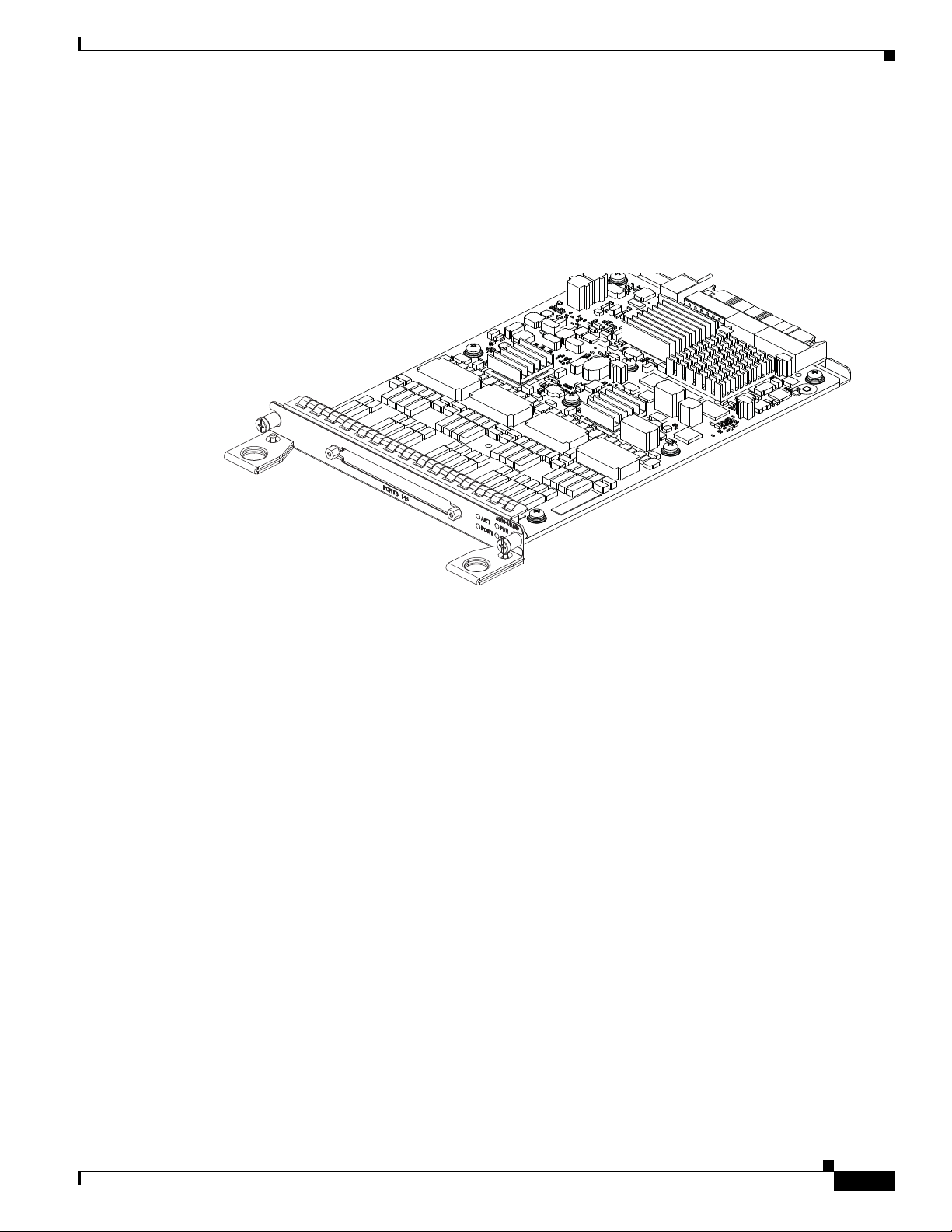
Gigabit Ethernet RJ45 Interface Module
The Gigabit Ethernet RJ45 interface module provides eight Gigabi t Ethernet c opper ports. Figure 1-5
shows the interface module.
Figure 1-5 8 x 1 GE Gigabit Ethernet RJ45 (Copper) Interface Module
1-10
For more information about installing an RJ45 Gigabit Ethernet module, see the “Interface Module
Installation” section on page 3-14.
Cisco ASR 903 Router Hardware Installation Guide
OL-25178-04
Page 23
Chapter 1 Cisco ASR 903 Router Overview
282437
10 Gigabit Ethernet XFP Interface Module
The 10 Gigabit Ethernet XFP interface module provides a single port supporting a 10 Gigabit Ethernet
XFP module. Figure 1-6 shows the interface module.
Figure 1-6 1 x 10 GE Gigabit Ethernet XFP Interface Module
Cisco ASR 903 Router Features
Note 10 Gigabit Ethernet interface modules are not su pporte d in slots 4 a nd 5.
Supported SFP Modules
The 10 Gigabit Ethernet SFP interface module supports the following SFP modules:
• DWDM-XFP-30.33
• DWDM-XFP-31.12
• DWDM-XFP-31.90
• DWDM-XFP-32.68
• DWDM-XFP-34.25
• DWDM-XFP-35.04
• DWDM-XFP-35.82
• DWDM-XFP-36.61
• DWDM-XFP-38.19
• DWDM-XFP-38.98v
• DWDM-XFP-39.77
• DWDM-XFP-40.56
• DWDM-XFP-42.14
• DWDM-XFP-42.94
• DWDM-XFP-43.73
• DWDM-XFP-44.53
OL-25178-04
• DWDM-XFP-46.12
Cisco ASR 903 Router Hardware Installation Guide
1-11
Page 24

Cisco ASR 903 Router Features
• DWDM-XFP-46.92
• DWDM-XFP-47.72
• DWDM-XFP-48.51
• DWDM-XFP-50.12
• DWDM-XFP-50.92
• DWDM-XFP-51.72v
• DWDM-XFP-52.52
• DWDM-XFP-54.13
• DWDM-XFP-54.94
• DWDM-XFP-55.75
• DWDM-XFP-56.55
• DWDM-XFP-58.17
• DWDM-XFP-58.98
• DWDM-XFP-59.79
Chapter 1 Cisco ASR 903 Router Overview
• DWDM-XFP-60.61
• DWDM-XFP-1560.61
• DWDM-XFP-C
• ONS-XC-10G-EP
• XFP10GER-192IR-L
• XFP-10GER-OC192IR
• XFP-10GER-OC192IR-RGD
• XFP10GLR-192SR-L
• XFP-10GLR-OC192SR
• XFP-10GLR-OC192SR-RGD
• XFP-10G-MM-SR
• XFP-10GZR-OC192LR
• XFP-10GZR-OC192LR-RGD
For more information about installing a 10GE XFP module, see the “Interface Module Installation”
section on page 3-14.
1-12
Cisco ASR 903 Router Hardware Installation Guide
OL-25178-04
Page 25
Chapter 1 Cisco ASR 903 Router Overview
282441
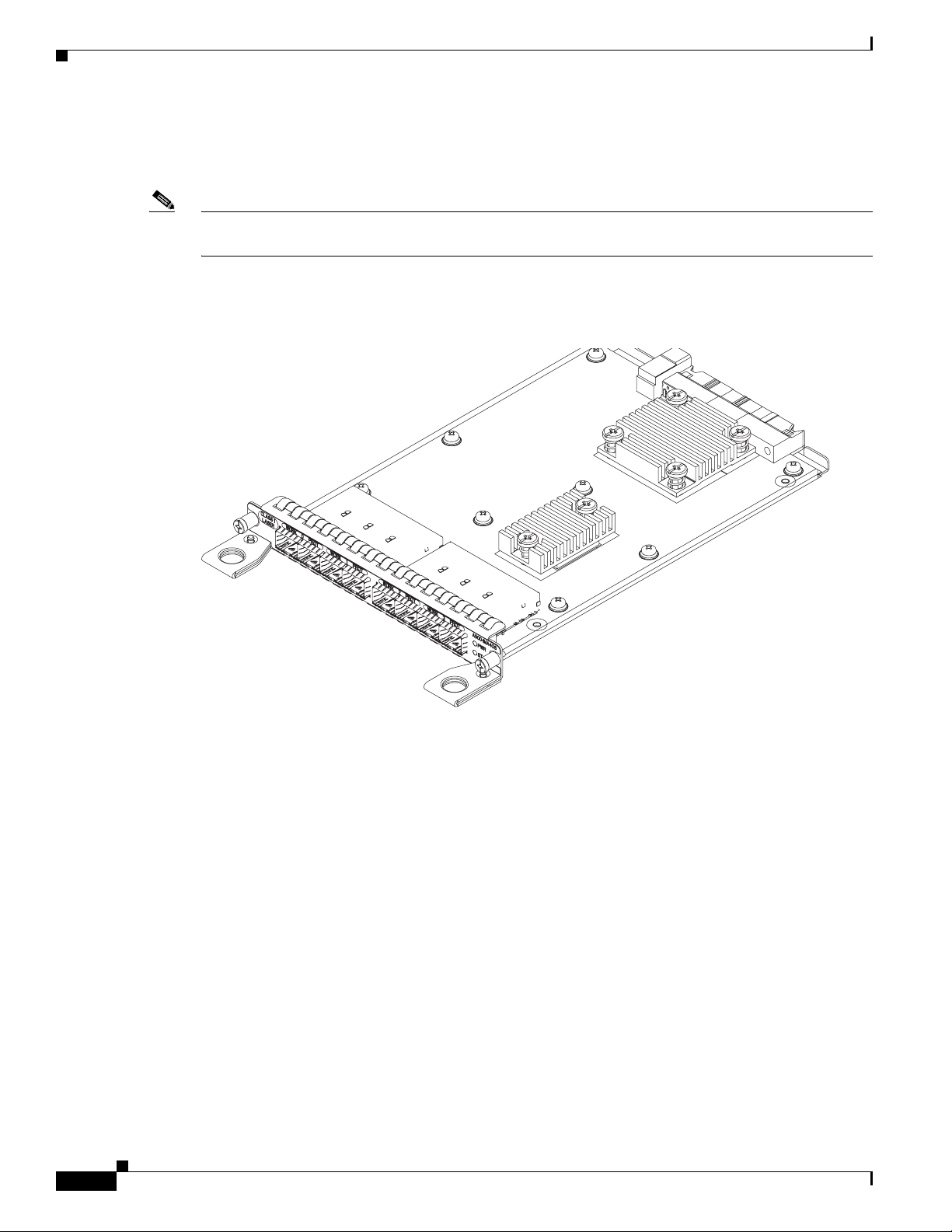
T1/E1 Interface Module
The T1/E1 interface module provides connecti vity for up to 16 T1/E1 po rts through a 100-pin Amplimite
connector. The T1/E1 interface module requires the use of a patch panel to provide RJ48 (T1) or BNC
(E1) connectors. Figure 1-7 shows the interface module.
Figure 1-7 16 x T1/E1 Interface Module
Cisco ASR 903 Router Features
For more information about instal ling a T1/E1 interf ace module, see the “Interf ace Module Installation”
section on page 3-14.
OL-25178-04
Cisco ASR 903 Router Hardware Installation Guide
1-13
Page 26
Cisco ASR 903 Router Features
282438
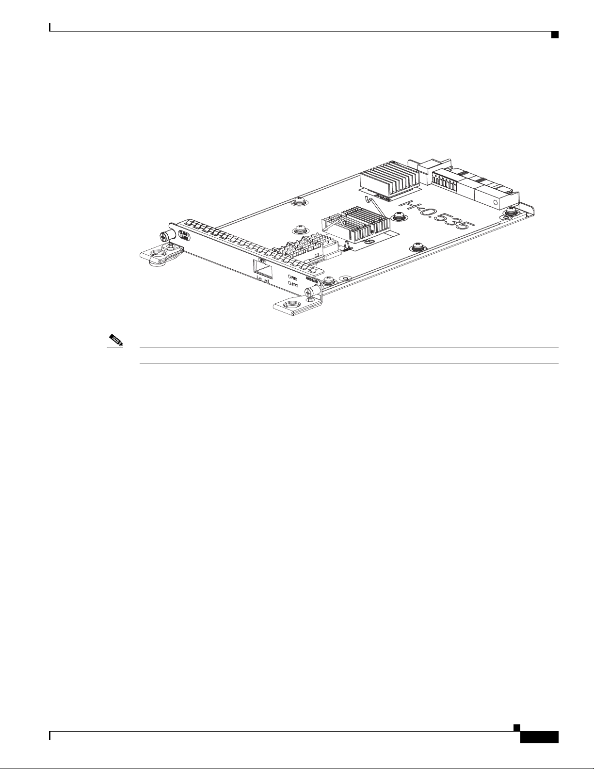
OC-3 Interface Module
The OC-3 interface module can operate as up to four STM-1 interfaces.
Note The optical interface module is designed for OC-3 and OC-12 traffic, but OC-12 functionality is not
currently supported.
Figure 1-8 shows the interface module.
Figure 1-8 4 x OC-3 Interface Module
Chapter 1 Cisco ASR 903 Router Overview
Supported SFP Modules
Cisco ASR 903 Router Hardware Installation Guide
1-14
The optical interface module supports the following optical transceivers:
• ONS-SC-155-EL
• ONS-SI-155-I1
• ONS-SI-155-L1
• ONS-SI-155-L2
• ONS-SI-155-SR-MM
For more information about installing an optical interface module, see the “Interface Module
Installation” section on page 3-14.
OL-25178-04
Page 27
Chapter 1 Cisco ASR 903 Router Overview
Temperature Sensor
The Cisco ASR 903 Router has a temperature sensor to detect overtemperature conditions inside the
chassis. The overtemperature detection trips at 75 degrees C +/- 5% with the ambient (inlet) trip point
at 67 degrees C. This condition is reported to the processor as an interrupt, and the softw are takes action
to generate the appropriate alarms.
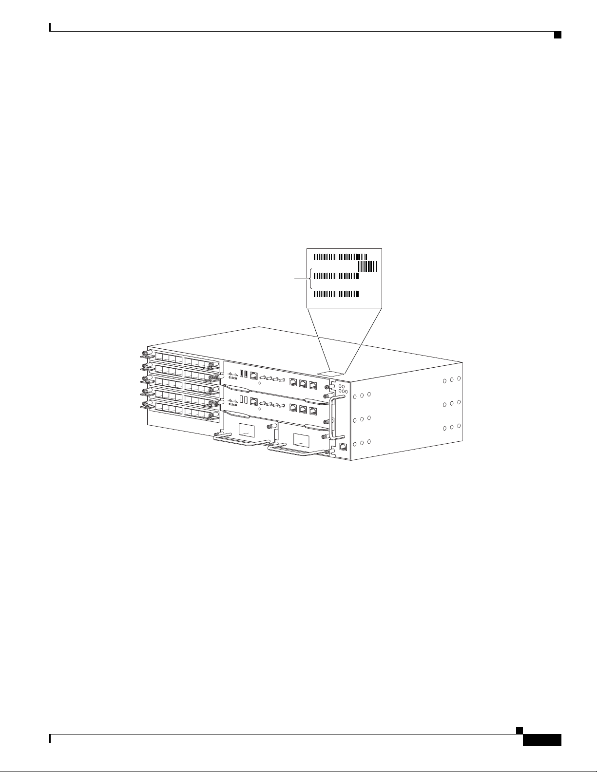
Serial Number Label Location
Figure 1-9 shows the serial number label location on the Cisco ASR 903 Router.
Figure 1-9 Cisco ASR 903 Router Serial Number Location
Interface Numbering
Interface Numbering
The Cisco ASR 903 Router chassis includes:
• Six interface module slots
Serial Number
11 letters and numbers
282407
OL-25178-04
• Two RSP module slots
• Two power supply slots
• One fan tray slot
Each network interface on a Cisco ASR 903 Router is identified by a slot number and a port number.
Cisco ASR 903 Router Hardware Installation Guide
1-15
Page 28
Regulatory Compliance
GE-0 GE-1 GE-2 GE-3 GE-4 GE-5 GE-6 GE-7
PWR
STAT
GE-0 GE-1 GE-2 GE-3 GE-4 GE-5 GE-6 GE-7
PWR
STAT
GE-0 GE-1 GE-2 GE-3 GE-4 GE-5 GE-6 GE-7
PWR
STAT
PWR
STAT
L 0 S L 1 S L 2 S L 3 S L 4 S L 5 S L 6 S L 7 S
PWR
STAT
L 0 S L 1 S L 2 S L 3 S L 4 S L 5 S L 6 S L 7 S
PWR
STAT
L 0 S L 1 S L 2 S L 3 S L 4 S L 5 S L 6 S L 7 S
INPUT
OK
OUTPUT
FAIL
24V—60V 28A
INPUT
OK
OUTPUT
FAIL
24V—60V 28A
RUDY RSP
MEM TOD BITS MGMT
ENET
1PPSIN1PPS
OUT
1OMHZ
OUT
1OMHZ
IN
CONSOLE
SYNC
ACT
PWR
STAT
RUDY RSP
MEM TOD BITS MGMT
ENET
1PPSIN1PPS
OUT
1OMHZ
OUT
1OMHZ
IN
CONSOLE
SYNC
ACT
PWR
STAT
ALARM
FAN TEMP
CRIT MAJ MIN
209290
2 31
45
11
10
9
8
7
6
Chapter 1 Cisco ASR 903 Router Overview
Figure 1-10 shows interface numbering in a Cisco ASR 903 Router.
Figure 1-10 Cisco ASR 903 Router Slot Numbers
1 RSP slot 1
2 RSP slot 0
3Fan tray slot
4 Power supply slot 1
5 Power supply slot 0
6 Interface module sl ot 0
7 Interface module sl ot 1
8 Interface module sl ot 2
9 Interface module sl ot 3
10 Interface module slot 4
11 Interface module slot 5
Following is an explanation of the slot or port numbering:
• The n u m b e r i n g f o r m a t is Interface type slot or interface number. Inte r fa c e ( p o r t ) n u m b e r s b eg i n a t
logical 0 for each interface type.
• Interface module slots are numbered from bottom to top, with logical interfaces on each module
numbered from left to right. Interfaces are hard-wired. Therefore, port 0 is always logical interface
0/0, port 1 is always logical interface 0/1, and so on.
Regulatory Compliance
1-16
Cisco ASR 903 Router Hardware Installation Guide
For regulatory compliance and safety information, see the Regulatory Compliance and Safety
Information for the Cisco ASR 903 Router document.
OL-25178-04
Page 29

Preparing for Installation
The following sections describe how to prepare for the installation of the Cisco ASR 903 Router at your
site:
• Safety Guidelines, page 2-1
• Site Planning, page 2-9
• Receiving the Cisco ASR 903 Router, page 2-19
Safety Guidelines
Before you begin the installation of the Cisco ASR 903 Router, review the safety guidelines in this
chapter to avoid injuring yourself or damaging the equipment.
In addition, before replacing, configuring, or maintaining the Cisco ASR 903 Router, review the safety
warnings listed in Regulatory Compliance and Safety Information for the Cisco ASR 903 Router.
CHAPTER
2
The following sections describe the safety guidelines for the Cisco ASR 903 Router:
• Standard Warning Statements, page 2-2
• Safety Guidelines for Personal Safety and Equipment Protection, page 2-3
• Safety Precautions for Module Installation and Removal, page 2-3
• Safety with Electricity, page 2-4
• Power Supply Considerations, page 2-8
• Preventing ESD Damage, page 2-8
OL-25178-04
Cisco ASR 903 Router Hardware Installation Guide
2-1
Page 30
Safety Guidelines
Standard Warning Statements
To see translations of the warnings that appear in this publication, refer to the Regulatory Compliance
and Safety Information document that accompanied this device.
Chapter 2 Preparing for Installation
Warning
Warning
Warning
Warning
Warning
To prevent bodily injury when mounting or servicing this unit in a rack, you must take special
precautions to ensure that the sy stem remains stable. The followin g guidelines are provided to ensure
your safety:
this unit in a partially filled rack, load the rack from the bottom to the top with the heaviest component at the bottom
of the rack. If the rack is provided with stabilizing devices, install the stabilizers before mounting or servicing the unit
in the rack.
This unit should be mounted at the bottom of the rack if it is the only unit in the rack. When mounting
Statement 1006
This unit is intended for installation in restricted access areas. A restricted access area can be
accessed only through the use of a special tool, lock and key, or other means of security.
Statement 1017
Ultimate disposal of this product should be handled according to all national laws and regulations.
Statement 1040
To prevent the system from overheating, do not operate it in an area that exceeds the maximum
recommended ambient temperature of 149°F (65°C).
The chassis should be mounted on a rack that is permanently affixed to the building.
Statement 1047
Statement 1049
2-2
Warning
IMPORTANT SAFETY INSTRUCTIONS: This warning symbol means danger. You are in a situation that
could cause bodily injury. Before you work on any equipment, be aware of the hazards involved with
electrical circuitry and be familiar with standard practices for preventing accidents. Use the
statement number provided at the end of each warning to locate its translation in the translated safety
warnings that accompanied this device.
Warning
This is a Class A Device and is registered for EMC requirements for industrial use. The seller or buyer
should be aware of this. If this type was sold or purchased by mistake, it should be replaced with a
Warning
residential-use type.
This is a class A product. In a domestic environment this product may cause radio interference in
Statement 294
which case the user may be required to take adequate measures.
Warning
This equipment is in compliance with the essential requirements and other relevant provisions of
Directive 1999/5/EC.
Cisco ASR 903 Router Hardware Installation Guide
Statement 1071
Statement 340
OL-25178-04
Page 31

Chapter 2 Preparing for Installation
Safety Guidelines for Personal Safety and Equipment Protection
The following guidelines help ensure your safety and protect the equipment. This list does not include
all the potentially hazardous situations. Therefore, you should be on alert.
• Before moving the system, always disconnect all the power cords and interface cables.
• Never assume that power is disconnected from a circuit; always check.
• Before and after installation, keep the chassis area clear and dust-free.
• Keep tools and assembly components away from walk areas where you or others could trip over
them.
• Do not work alone if potentially hazardous conditions exist.
• Do not perform any action that creates a potential ha zard t o pe op le o r m akes th e equ ipm e nt u nsafe.
• Do not wear loose clothing that may get caught in the chassis.
• When working under conditions that may be hazardous to your eyes, wear safety glasses.
Safety Precautions for Module Installation and Removal
Safety Guidelines
Warning
Warning
Warning
Warning
Warning
Be sure to observe the following safety precautions when you work on the router.
To see translations of the warnings that appear in this publication, refer to the Regulatory Compliance
and Safety Information document that accompanied this device.
Class 1 laser product.
Do not stare into the beam or view it directly with optical instruments.
Invisible laser radiation present.
Hazardous network voltages are present in WAN ports regardless of whether power to the unit is OFF
or ON. To avoid electric shock, use caution when working near WAN ports. When detaching cables,
detach the end away from the unit first.
Blank faceplates and cover panels serve three important functions: they prevent exposure to
hazardous voltages and currents inside the chassis; they contain electromagnetic interference (EMI)
that might disrupt other equipment; and they direct the flow of cooling air through the chassis. Do not
operate the system unless all cards, faceplates, front covers, and rear covers are in place.
Statement 1029
Statement 1008
Statement 1011
Statement 1016
Statement 1026
OL-25178-04
Warning
Hazardous voltage or energy is present on the backplane when the system is operating. Use caution
when servicing.
Statement 1034
Cisco ASR 903 Router Hardware Installation Guide
2-3
Page 32

Safety Guidelines
Chapter 2 Preparing for Installation
Warning
Invisible laser radiation may be emitted from disconnected fibers or connectors. Do not stare into
beams or view directly with optical instruments.
Safety with Electricity
Warning
Warning
Warning
Warning
Before working on a chassis or working near power supplies, unplug the power cord on AC units;
disconnect the power at the circuit breaker on DC units.
Before working on equipment that is connected to power lines, remove jewelry (including rings,
necklaces, and watches). Metal objects will heat up when connected to power and ground and can
cause serious burns or weld the metal object to the terminals.
Do not work on the system or connect or disconnect cables during periods of lightning activity.
Statement 1001
Before performing any of the following procedures, ensure that powe r is removed from the DC circuit.
Statement 1003
Statement 1051
Statement 12
Statement 43
Warning
Warning
Warning
Warning
Warning
Read the installation instructions before connecting the system to the power source.
Statement 1004
This product relies on the building’ s installation for short-circuit (overcurrent) protection. Ensure that
the protective device is rated: For a -48/-60 VDC installation, the wire shall be 12 AWG minimum with
a 20 A branch circuit breaker. For a 24 VDC installation, the wire shall be 8 AWG minimum with a 40
A branch circuit breaker.
Statement 1005
This product relies on the building’s installation for short-circuit (overcurrent) protection. For an AC
installation, ensure that the branch circuit breaker is rated a maximum 20A.
There is the danger of explosion if the battery is replaced incorrectly. Replace the battery only with
the same or equivalent type recommended by the manufacturer. Dispose of used batteries according
to the manufacturer’s instructions.
Statement 1015
This unit is intended for installation in restricted access areas. A restricted access area can be
accessed only through the use of a special tool, lock and key, or other means of security.
Statement 1017
2-4
Cisco ASR 903 Router Hardware Installation Guide
OL-25178-04
Page 33

Chapter 2 Preparing for Installation
Safety Guidelines
Warning
Warning
Warning
Warning
Warning
When you connect or disconnect the power and relay connector with power applied, an electrical a rc
can occur. This could cause an explosion in hazardous area installations. Be sure that power is
removed from the switch and alarm circuit. Be sure that power cannot be accidentally turned on or
verify that the area is nonhazardous before proceeding. Failure to securely tighten the power and
relay connector captive screws can result in an electrical arc if the connector is accidentally
removed.
T ake care when c onnecting u nits to the supply circ uit so that wiring is not overloaded.
Statement 1058
Statement 1018
The plug-socket combination must be accessible at all times, because it serves as the main
disconnecting device.
Statement 1019
T o avoid electric shock, do not connect safety extra-low voltage (SELV) circuits to telephone-network
voltage (TNV) circuits. LAN ports contain SELV circuits, and WAN ports contain TNV circuits. Some
LAN and WAN ports both use RJ45 connectors. Use caution when connecting cables.
A readily accessible two-poled disconnect device mu st be incorporated in the fixed wiring.
Statement 1021
Statement
1022
Warning
Warning
Warning
Warning
Warning
Warning
To reduce the risk of fire, use only 26 AWG or larger telecommunication line cord.
Statement 1023
This equipment must be grounded. Never defeat the ground conductor or operate the equipment in the
absence of a suitably installed ground conductor. Contact the appropriate electrical inspection
authority or an electrician if you are uncertain that suitable grounding is available.
Use copper conductors only.
Statement 1025
Statement 1024
This unit might have more than one power supply connection. All connections must be removed to
de-energize the unit.
Statement 1028
To prevent personal injury or damage to the chassis, never attempt to lift or tilt the chassis using the
handles on modules (such as power supplies, fans, or cards); these types of handles are not designe d
to support the weight of the unit.
Statement 1032
Connect the unit only to DC power source that complies with the safety extra-low voltage (SELV)
requirements in IEC 60950 based safety standards.
Statement 1033
OL-25178-04
Cisco ASR 903 Router Hardware Installation Guide
2-5
Page 34

Safety Guidelines
Chapter 2 Preparing for Installation
Warning
Warning
Warning
Warning
Warning
Do not use this product near water; for example, near a bath tub, wash bowl, kitchen sink or laundry
tub, in a wet basement, or near a swimming pool.
Statement 1035
Never install telephone jacks in wet locations unless the jack is specifically designed for
wet locations.
Statement 1036
Before opening the unit, disconnect the telephone-network cables to avoid contact with
telephone-network voltages.
Statement 1041
This equipment must be installed and maintained by service personnel as defined by AS/NZS 3260.
Incorrectly connecting this equipment to a general-purpose outlet could be hazardous. The
telecommunications lines must be disconnected 1) before unplugging the main power connector or 2)
while the housing is open, or both.
Statement 1043
This product requires short-circuit (overturned) protection, to be provided as part of the building
installation. Install only in accordance with national and local wiring regulations.
Statement 1045
Warning
Warning
Warning
Warning
Warning
When installing or replacing the unit, the ground connection must always be made first and
disconnected last.
Never install an AC power module and a DC power module in the same chassis.
Statement 1046
Statement 1050
Failure to securely tighten the power and relay connector captive screws can result in an electrical
arc if the connector is accidentally removed.
Statement 1058
This equipment is intended to be grounded. Ensure that the host is connected to earth ground during
normal use.
If you connect or disconnect the console cable with power applied to the switch or any device on th e
network, an electrical arc can occur. This could cause an explosion in hazardous location
installations. Be sure that power is removed or the area is nonhazardous before proceeding. To verify
switch operation, perform POST on the switch in a nonhazardous location before installation.
Statement 1065
2-6
Warning
Cisco ASR 903 Router Hardware Installation Guide
Installation of the equipment must comply with local and national electrical codes.
Statement 1074
OL-25178-04
Page 35

Chapter 2 Preparing for Installation
Safety Guidelines
Warning
Hazardous voltage or energy may be present on DC power terminals. Always replace cover when
terminals are not in service. Be sure uninsulated conductors are not accessible when cover is in
place.
Statement 1075
When working on equipment powered by electricity, follow these guidelines:
• Locate the room’s emergency power-off switch. If an electrical accident occurs, you will be able to
quickly turn off the power.
• Before working on the system, turn off the DC main circuit breaker and disconnect the power
terminal block cable.
• Before doing the following, disconnect all power:
–
Working on or near power supplies
–
Installing or removing a router chassis or network processor module
–
Performing most hardware upgrades
• Never install equipment that appears damaged.
• Carefully examine your work area for possible hazards, such as moist floors, ungrounded power
extension cables, and missing safety grounds.
• Never assume that power is disconnected from a circuit; always check.
• Never perform any action that creates a potential hazard to people or makes the equipment unsafe.
• If an electrical accident occurs, proceed as follows:
–
Use caution, and do not become a victim yourself.
–
Turn off power to the router.
–
If possible, send another person to g et medical aid. Otherwise, determine the condition of the
victim, and then call for help.
–
Determine whether the person needs rescue breathing or external cardiac compressions; then
take appropriate action.
In addition, use the following guidelines when working with any equipment th at is disconnected from a
power source, but still connected to telephone wiring or network cabling:
• Never install telephone wiring during a lightning storm.
• Never install telephone jacks in wet locations unless the jack is specifically designed for it.
• Never touch uninsulated telephone wires or terminals unless the telephone line is disconnected at
the network interface.
• When installing or modifying telephone lines, use caution.
OL-25178-04
Cisco ASR 903 Router Hardware Installation Guide
2-7
Page 36

Safety Guidelines
Power Supply Considerations
Check the power at your site to ensure that you are receiving clean power (free of spikes and noise).
Install a power conditioner if necessary.
Chapter 2 Preparing for Installation
Warning
This equipment is designed for connection to TN and IT power systems.
Preventing ESD Damage
Warning
This equipment needs to be grounded. Use a green and yellow 6 AWG ground wire to connect the host
to earth ground during normal use.
Electrostatic discharge (ESD) can damage equipme nt and impai r electrica l circuitry. ESD can occur
when electronic printed circuit cards are improperly handled and can cause complete or intermittent
failures. When removing and replacing modules, always follow ESD prevention procedures:
• Ensure that the router chassis is electrically connected to earth ground.
• W ear an ESD-pre ventive wrist strap, ensur ing that it mak es good skin contact. To channel unwanted
ESD voltages safely to ground, connect the clip to an unpainted surface of the chassis frame. To
guard against ESD damage and shocks, the wrist strap and cord must operate effectively.
• If no wrist strap is available, ground yourself by touching a metal part of the chassis.
• When installing a component, use any available ejector levers or captive installation screws to
properly seat the bus connectors in the backplane or midplane. These devices prevent accidental
removal, provide proper grounding for the system, and help to ensure that bus connectors are
properly seated.
• When removing a component, use available ejector levers or captive installation screws, if any, to
release the bus connectors from the backplane or midplane.
• Handle components by their handles or edges only; do not touch the printed circuit boards or
connectors.
Statement 16
Statement 383
2-8
• Place a removed component board side up on an antistatic surface or in a static-shielding container.
If you plan to return the component to the factory, immediately place it in a static-shielding
container.
• Avoid contact between the printed circuit boards and clothing. The wrist strap only protects
components from ESD voltages on the body; ESD voltages on clothing can still cause damage.
• Never attempt to remove the printed circuit board from the metal carrier.
Note For the safety of your equipment, periodically check the resistance value of the antistatic wrist strap. It
should be between 1 and 10 Mohm.
Cisco ASR 903 Router Hardware Installation Guide
OL-25178-04
Page 37

Chapter 2 Preparing for Installation
Site Planning
The following sections describe how to plan for the installation of the Cisco ASR 903 Router:
• General Precautions, page 2-9
• Site Planning Checklist, page 2-9
• Site Selection Guidelines, pag e 2-10
• Air Flow Guidelines, page 2-11
• Floor Loading Considerations, page 2-12
• Site Power Guidelines, page 2-12
• Site Cabling Guidelines, page 2-13
• Rack-Mounting Guidelines, page 2-15
• Installation Checklist, page 2-18
• Creating a Site Log, page 2-19
Site Planning
General Precautions
Observe the following general precautions when using and working with your Cisco ASR 903 Router
system:
• Keep your system components aw ay from radiators and heat sou rces and do not block cool ing vents.
• Do not spill food or liquids on your system components and never operate the product in a wet
environment.
• Do not push any objects into the openings of your system components. Doing so can cause fire or
electric shock by shorting out interior components.
• Position system cables and power supply cables care fully . Route system cables and the power supply
cable and plug so that they cannot be stepped on or tripped over. Be sure that nothing else rests on
your system component cables or power cable.
• Do not modify power cables or plugs. Consult a licensed electrician or your power company for site
modifications. Always follow your local and national wiring rules.
• If you turn off your system, wait at least 30 seconds before turning it on again to avoid system
component damage.
Site Planning Checklist
Use the following checklist to perform and account for all the site planning tasks described in this
chapter:
OL-25178-04
• The site meets the environmental requirements.
• The site’s air conditioning system can compensate for the heat dissipation of the
Cisco ASR 903 Router.
• The floor space that the Cisco ASR 903 Router occupies can support the weight of the system.
• Electrical service to the site complies with the requirements.
• The electrical circuit servicing the Cisco ASR 903 Router complies with the requirements.
Cisco ASR 903 Router Hardware Installation Guide
2-9
Page 38

Site Planning
• Consideration has been given to the console port wiring and limitations of the cabling involved,
according to TIA/EIA-232F.
• The Cisco ASR 903 Router Ethernet cabling distances are within limitations.
• The equipment rack in which you plan to install the Cisco ASR 903 Router complies with
requirements.
• In selecting the location of the r ack, caref ul consideration has been given to safety, ease of
maintenance, and proper airflow.
Site Selection Guidelines
The Cisco ASR 903 Router requires specific environmental operating conditions. Temperature,
humidity, altitude, and vibration can affect the performance and reliability of the router. The following
sections provide specific information to help you plan for the proper operating environment.
The Cisco ASR 903 Router is designed to meet the industry EMC, safety, and environmental standards
described in the Regulatory, Safety, and Compliance Information for the Cisco AS R 903 Router.
Chapter 2 Preparing for Installation
Environmental Requirements
Environmental monitoring in the Cisco ASR 903 Router protects the system and components from
damage caused by excessive voltage and temperature conditions. To ensure normal operation and avoid
unnecessary maintenance, plan and prepare your site configuration before installation. After installation,
make sure that the site maintains the environmental characteristics described in “System Specif ications”
section on page 2.
Physical Characteristics
Be familiar with the physical characteristics of the Cisco ASR 903 Router to assist you in placing the
system in the proper location. For more information, see the “System Specifications” section on page 2.
2-10
Cisco ASR 903 Router Hardware Installation Guide
OL-25178-04
Page 39

Chapter 2 Preparing for Installation
344738
Room air
Air exhaust
Air Flow Guidelines
Cool air is circulated through the Cisco ASR 903 Router by a fan tray located along the right side of the
router. Air flow is side-to-side, right to left, as shown in “Cisco ASR 903 Router Chassis Air Flow”.
Figure 2-1 Cisco ASR 903 Router Chassis Air Flow
Site Planning
The fan trays maintain acceptable operating temperatures for the internal components b y drawing in cool
air through the vents, and circulating the air through the chassis.
The following guidelines will help you plan your equipment rack configuration:
• To ensure adequate air flow through the equipment rack, we recommend that you maintain a
clearance of at least 80 mm on each side of the rack at all times.
• If airflow through the equipment rack and the routers that occupy it is blocked or restricted, or if the
ambient air being drawn into the rack is too warm, an overtemperature condition can occur within
the rack and the routers that occupy it.
• The site should also be as dust-free as possible. Dust tends to clog the router fans, reducing the flow
of cooling air through the equipment rack and the routers that occupy it, thus increasing the risk of
an overtemperature condition.
• Enclosed racks must have adequate ventilation. Ensure that the rack is not congested, because each
router generates heat. An enclosed rack should have louvered sides and a fan to provi de cooling air.
Heat that is generated by the equipment near the bottom of the rack can be drawn upward into the
intake ports of the equipment above.
• When mounting a chassis in an open rack, ensure that the rack frame does not block the side intak es
and the exhaust fans.
• When rack-installed equipment fails, especially equipment in an enclosed rack, try operating the
equipment by itself, if possible. Power off all other equipment in the rack (and in adjacent racks) to
give the router maximum cooling air and clean power.
• Avoid locating the Cisco ASR 903 Router in a location in which the chassis air intake vents may
draw in the exhaust air from adjacen t equipment. Consid er ho w the air flo w s through the router; the
airflow direction is side to side, with ambient air drawn in from the vents located on the front right
of the chassis.
OL-25178-04
Cisco ASR 903 Router Hardware Installation Guide
2-11
Page 40

Site Planning
Air Flow Guidelines for Enclosed Rack Installation
To install a Cisco ASR 903 Router in a 4-post enclosed cabinet, the front and rear doors of the cabinet
must be removed or be perforated with a minimum of 65% open area (70% for ETSI 800mm racks).
If you are mounting the chassis in a 4-post enclosed cabinet, ensure that yo u hav e a minimum of 6 inches
(15.24 cm) of clearance on each side of the chassis.
Floor Loading Considerations
Ensure that the floor under th e rack supporting the Cisco ASR 903 Routers is capable of supporting the
combined weight of the rack and all the other installed equipment.
To assess the weight of a fully configured Cisco ASR 903 Router, refer to “System Specifications”
section on page 1-2.
For additional information about floor lo ading requirements, consult GR-63-CORE, Network Equipment
Building System (NEBS) Requirements: Physical Protection.
Chapter 2 Preparing for Installation
Site Power Guidelines
The Cisco ASR 903 Router has specific power and electrical wiring requirements. Adhering to these
requirements ensures reliable operation of the system. Follow these precautions and recommendations
when planning your site power for the Cisco ASR 903 Router:
• The redundant power option provides a second, identical power supply to ensure that power to the
chassis continues uninterrupted if one p ower supply fails or input power on on e line fails.
• In systems configured with the redundant power option, connect each of the two power supplies to
a separate input power source. If you fail t o do this, you r system might b e susceptible to to tal po wer
failure due to a fault in the external wiring or a tripped circuit breaker.
• To prevent a loss of input power, be sure that the total maximum load on each circuit supplying the
power supplies is within the current ratings of the wiring and the breakers.
• Check the power at your site before installation and periodi cally after installation to en sure that you
are receiving clean power. Install a power conditioner if necessary.
• Provide proper grounding to avoid personal injury and damage to the equipment due to lightning
striking power lines or due to po wer surges. The chassis ground must be attached to a central office
or other interior ground system.
Caution This product requires short-circuit (overcurrent) protection, to be provided as part of the building
installation. Install only in acc ordance with national and local wiring regulations.
2-12
Note The Cisco ASR 903 Router installation must comply with all the applicable codes and is approved for
use with copper conductors only. The ground bond f asten ing hardw are should b e of compati ble material
and preclude loosening, deterioration, and electrochemical corrosion of hardware and joined material.
Attachment of the chassis ground to a central office or other interior ground system must be made with
a 6 AWG gauge wire, copper ground conductor at a minimum.
Cisco ASR 903 Router Hardware Installation Guide
OL-25178-04
Page 41

Chapter 2 Preparing for Installation
The maximum power draw of the Cisco ASR 903 Router chassis and its configurable hardware
components are listed in the fo llowing table. The maximum power draw values are not affected by
whether the router chassis contains 1 or 2 power supplies AC or DC.
Hardware component(s) Maximum power draw value
Router chassis with 2 power supplies, 1 fan tray, and 1 RSP1A 195 W
Router chassis with 2 power supplies, 1 fan tray, and 1 RSP1B 210 W
A900-RSP1A-55 (standby) 100 W
A900-RSP1B-55 (standby) 100 W
A900-IMA1X (1-port 10 GE XFP interface module) 13.0 W
A900-IMA8T (8-port 1 GE RJ45 interface module) 17.5 W
A900-IMA8S (8-port 1 GE SFP interface module) 17.5 W
A900-IMA16D (16-port T1/E1 interface module) 14.5 W
A900-IMA4OS (4-Port OC3 interface Module) 26 W
Site Planning
Electrical Circuit Requirements
Each Cisco ASR 903 Router requires a dedicated electrical circuit. If you equip it with dual power feeds,
provide a separate circuit for each power supply to avoid compromising the power redundancy feature.
The Cisco ASR 903 Routers can be powered by a DC source or an AC source. Ensure that equipment
grounding is present and observe the power strip ratings. Make sure that the total ampere rating of all
products plugged into the power strip does not exceed 80% of the rating.
For more information about the Cisco ASR 903 Router power supply, see the “Power Supply Features”
section on page 1-3.
Site Cabling Guidelines
This section contains guidelines for wiring and cabling at your site. When preparing your site for
network connections to the Cisco ASR 903 Router, consider the type of cable required for each
component, and the cable limitations. Consider the distance limitations for signaling, electromagnetic
interference (EMI), and connector compatibility . Possible cab le types are fib er , thick or thin coaxial, foil
twisted-pair, or unshielded twisted-pair cabling.
Also consider any additional interface equipment you need, such as transceivers, hubs, switches,
modems, channel service units (CSU), or data service units (DSU).
Before you begin, read these important notes about cabling:
• The T1/E1 interface module for the Cisco ASR 903 Router uses a high-density connector that
requires the use of a T1/E1 interface cable and a customer-provided patch panel. For more
information, see “Connecting T1/E1 cables” section on page 3-40.
OL-25178-04
• Shielded cables must be used to connect to the DB-25 alarm connector on the fan tray in order to
comply with FCC/EN55022/CISPR22 Class A emissions requirements. For information about the
fan tray alarm port, see “Connecting the Fan Tray Alarm Port” section on page 3-42.
Before you install the Cisco ASR 903 Router, have all the additional external equipment and cables on
hand. For information about ordering, contact a Ci sco customer service representative.
Cisco ASR 903 Router Hardware Installation Guide
2-13
Page 42

Site Planning
The extent of your network and the distances between the network interface connections depend in part
on the following factors:
• Signal type
• Signal speed
• Transmission medium
The distance and rate limits referenced in the following section s are the IEEE-recommended maximum
speeds and distances for signaling purposes. Use this information as a guideline in planning your
network connections prior to installi ng the Cisco ASR 903 Router.
If wires exceed the recommended distances, or if wires pass between buildings, give special
consideration to the effect of a lightning strike in your vicinity. The electromagnetic pulse caused by
lightning or other high-energy pheno m en a can easily couple enough energy into unshielded conductors
to destroy electronic devices. If you have had problems of this sort in the past, you may want to consult
experts in electrical surge suppression and shielding.
Asynchronous Terminal Connections
The RSP provides a console port to connect a terminal or computer for local console access. The port
has an RJ45 connector and supports RS-232 asynchronous data with distance recommendations
specified in the IEEE RS-232 standard.
Chapter 2 Preparing for Installation
Interference Considerations
When wires are run for any significant distance, there is a risk that stray signals will be induced on the
wires as interference. If interference signals are strong, they can cause data errors or damage to the
equipment.
The following sections describe sources of interference and how to minimize its effects on the
Cisco ASR 903 Router system.
Electromagnetic Interference
All equipment powered by AC current can propagate electrical energy that can cause EMI and possibly
affect the operation of other equipment. The typical sources of EMI are equipment power cords and
power service cables from electric utility companies.
Strong EMI can destroy the signal driv ers and recei ver s in the Cisco ASR 903 Router and even create an
electrical hazard by causing power surges through the power lines into installed equipment. These
problems are rare but could be catastrophic.
To resolve these problems, you need specialized knowledge and equipment that could consume
substantial time and money. However, you can ensure that you have a properly grounded and shielded
electrical environment, paying special attention to the need for electrical surge suppression.
For information about the electrode magnetic compliance standards supported on the
Cisco ASR 903 Router, see Regulatory Compliance and Safety Information for the
Cisco ASR 903 Router.
Radio Frequency Interference
When electromagnetic fields act over a long distance, radio frequency interference (RFI) may be
propagated. Building wiring can often a ct as an ante nna, receiving the RFI signals and creating more
EMI on the wiring.
Cisco ASR 903 Router Hardware Installation Guide
2-14
OL-25178-04
Page 43

Chapter 2 Preparing for Installation
If you use twisted-pair cable in your plant wiring with a good distribution of grounding conductors, the
plant wiring is unlikely to emit radio interference. If you exceed the recommended distances, use a
high-quality twisted-pair cable with one ground conductor for each data signal.
Lightning and AC Power Fault Interference
If signal wires exceed the recommended cabling distances, or if signal wires pass between buildings, you
should consider the effect that a lightning strike in your vicinity might have on the
Cisco ASR 903 Router.
The electromagnetic pulse (EMP) generated by lightning or other high-energy phenomena can couple
enough energy into unshielded conductors to damage or destroy electronic equipment. If you have
previously experien ced such problems, y ou should consult with RFI and EMI e xperts to ensure that yo u
have adequate electrical surge su ppression an d shielding of signal cables in your Cisco ASR 903 Router
operating environment.
Rack-Mounting Guidelines
The following sections provide guidelines for rack-mounting the Cisco ASR 903 Router:
• Precautions for Rack-Mounting, page 2-15
Site Planning
• Rack Selection Guidelines, page 2-15
• Equipment Rack Guidelines, page 2-16
Precautions for Rack-Mounting
The following rack-mount guidelines are provided to ensure your safety:
• Do not move large racks by yourself. Due to the height and weight of a rack, a minimum of two
people are required to accomplish this task.
• Ensure that the rack is level and stable before extending a component from the rack.
• Ensure that proper airflow is provided to the components in the rack.
• Do not step on or stand on any component or system when servicing other systems or components
in a rack.
• When mounting the Cisco ASR 903 Router in a partially filled rack, load the rack from the bottom
to the top, with the heaviest component at the bottom of the rack.
• If the rack is provided with stabilizing devices, install the stabilizers before mounting or servicing
the unit in the rack.
Rack Selection Guidelines
The Cisco ASR 903 Router can be mounted in most two-post or four-post, 19-inch equipment racks that
comply with the Electronic Industries Association (EIA) standard for equipment racks (EIA-310-D
19-inch). The rack must have at least two posts with mounting flanges to mount the chassis.
OL-25178-04
Caution When mounting a chassis in any type of rack equipment, ensure that the inlet air to the chassis does not
exceed 65 degrees C.
Cisco ASR 903 Router Hardware Installation Guide
2-15
Page 44

Site Planning
Chapter 2 Preparing for Installation
The distance between the center lines of the mounting holes on the two mounting posts must be 18.31
inches ± 0.06 inch (46.50 cm ± 0.15 cm). The rack-mounting hardware included with the chassis is
suitable for most 19-inch equipment racks.
Consider installing the Cisco ASR 903 Router in a rack with the following features:
• Network Equipment Building System (NEBS) compliant, 19-inch (48.3 cm) wide rack.
• EIA or European Telecommunications Standards Institute (ETSI) hole patterns in the mounting
rails. The required mounting hardware is shipped with the Cisco ASR 903 Router. If the rack that
you plan to install the system in has metric-threaded rails, you must provide your own
metric-mounting hardware.
• Perforated top and open bottom for ventilation to prevent overheating.
• Leveling feet for stability.
Note The Cisco ASR 903 Router should not be installed in an enclosed rack because the chassis requires an
unobstructed flow of cooling air to maintain acceptable operating temperatures for its internal
components. Installing the router in any type of enclosed rack—even with the side doors
removed—could disrupt the air flow, trap heat next to the chassis, and cause an overtemperature
condition inside the router. If you use an enclosed rack, ensure that there are air vents on all sides of the
rack and there is proper ventilation.
Equipment Rack Guidelines
The placement of the rack can affect personnel safety, system maintenance, and the system’s ability to
operate within the environmental characteristics described in the “System Specifications” section on
page 1-2. Choose a proper location for the Cisco ASR 903 Router by following the follo wing guidelines.
Locating for Safety
If the Cisco ASR 903 Router is the heaviest or the only piece of equipment in the rack, consider
installing it at or near the bottom to ensure that the rack’s center of gravity is as low as possible.
For additional information about the proper placement of electronic equipment, consult the document
GR-63-CORE, Network Equipment Building System (NEBS) Requirements: Physical Protection.
Locating for Easy Maintenance
Keep at least 3 feet of clear space at the front and back of the rack. This space ensures that you can
remove the Cisco ASR 903 Router components and perform routine maintenance and upgrades easily.
A v oid installing the Cisco ASR 903 Router in a congested rack and consider ho w routi ng of cables from
other pieces of equipment in the same rack could affect access to the router cards.
The sides of the chassis must remain unobstructed to ensure adequate airflow and prevent overheating
inside the chassis.
Allow the following clearances for normal system maintenance:
• At the top of the chassis—At least 3 inches (7.6 cm)
2-16
• Sides of the chassis—3 to 4 ft (91.44 cm to 121.92 cm)
To avoid problems during installation and ongoing operations, follow these general precautions when
you plan equipment locations and connections:
Cisco ASR 903 Router Hardware Installation Guide
OL-25178-04
Page 45

Chapter 2 Preparing for Installation
• Use the show environment all command regularly to check the internal system status. The
• Keep the Cisco ASR 903 Router off the floor and out of areas that collect dust.
• Follow ESD-prevention procedures to avoid damage to equipment. Damage from static discharge
Locating for Proper Airflow
Ensure that the Cisco ASR 903 Router location has enough airflow to keep the system operating within
the environmental characteristics and the air temperature is sufficient to compensate for the heat
dissipated by the system. For more information, see “Air Flow Guidelines” section on page 2-11.
Site Planning
environmental monitor continually checks the interior chassis environment; it provides warnings
about high temperature and creates reports on other potentially dangerous occurrences. If warning
messages are displayed, take immediate action to identify the cause, and correct the problem.
can cause immediate or intermittent equipment failure.
OL-25178-04
Cisco ASR 903 Router Hardware Installation Guide
2-17
Page 46

Site Planning
Installation Checklist
To assist you with your installation and to provide a record of what was done by whom and when,
photocopy the Cisco ASR 903 Router Installation Checklist shown in Table 2-1. Use this to record the
completion and verification of each procedure. After the checklist is completed, place i t in your Site Log
along with the other records pertaining to your new Cisco router.
Table 2-1 Cisco ASR 903 Router Installation Checklist
Task
Date on which chassis received
Chassis and all accessories unpacked
Types and numbers of interfaces verified
Safety recommendations and guidelines reviewed
Installation Checklist copied
Site Log established and background information entered
Site power voltages verified
Site environmental specifications verified
Required passwords, IP addresses, device names, and so on, available
Required tools available
Network connection equipment available
Cable-management brackets installed (optional, but recommended)
AC power cables connected to AC sources and router
DC power cables connected to DC sources and router
Network interface cables and devices connected
System power turned on
System boot complete (STATUS LED is on)
Shared port adapters are operational
Correct software configuration displayed after system banner appears
Chapter 2 Preparing for Installation
Verified
By Date
2-18
Cisco ASR 903 Router Hardware Installation Guide
OL-25178-04
Page 47

Chapter 2 Preparing for Installation
132823
1
2
3
Creating a Site Log
The Site Log provides a record of all the actions related to installing and maintain ing t he rout er. Keep it
in an accessible place near the chassis so that anyone who performs tasks has access to it.
Create the Site Log prior to the installation. (See Appendix A, “Site Log” for more information on the
Site Log as well as a sample Site Log that can be used to make copies.)
Receiving the Cisco ASR 903 Router
Each Cisco ASR 903 Router chassis is shipped in a container that is strapped to a pallet, as illustrated in
Figure 2-2.
Figure 2-2 Cisco ASR 903 Router Packaged for Shipping
Receiving the Cisco ASR 903 Router
OL-25178-04
1 Outside carton 3 Packing straps
2 Pallet — —
Note We recommend that you have at least two people available to help with the installation and ensure safe
lifting.
Cisco ASR 903 Router Hardware Installation Guide
2-19
Page 48

Receiving the Cisco ASR 903 Router
Chassis-Lifting Guidelines
The chassis is not intended to be moved frequently. Before you install the system, ensure that your site
is properly prepared so that you can avoid having to move the chassis later to accommodate power
sources and network connections.
Two or more people are required to lift the chassis. Each time you lift the chassis or any heavy object,
follow these guidelines:
• Never attempt to lift the chassis by yourself. Because of the size and weight of the chassis, use at
least two people to safely lift and move it without causing injury to yourself or damaging the
equipment.
• Ensure that your footing is solid, and bala nce the weigh t of the chassi s between y our feet.
• Lift the chassis slowly; never move suddenly or twist your body as you lift.
• Keep your back straight and lift with your legs, not your back. If you must bend down to lift the
chassis, bend at the knees, not at the waist, to reduce the strain on your back muscles.
• Do not remove installed components from the chassis.
• Always disconnect all external cables before lifting or moving the chassis.
Chapter 2 Preparing for Installation
Warning
To prevent personal injury or damage to the chassis, never attempt to lift or tilt the chassis using the
handles on modules (such as power supplies, fans, or cards); these types of handles are not designe d
to support the weight of the unit. Lift the unit only by using handles that are an integral part of the
chassis, or by grasping the chassis underneath its lower edge.
Perform the following to lift a chassis:
Step 1 Each person should stand on either side of the chassis and place one hand under the air intake at the
bottom front of the chassis.
Step 2 With the other hand, grasp the top rear of the chassis under the air e xhaust , and carefully lift the chassis.
Tools and Equipment
You need the following tools and equipment to install and upgrade the router and its components:
• ESD-preventive cord and wrist strap
• Antistatic mat or antistatic foam
• Number 1 and Number 2 Phillips-head screwdrivers
• Flat-blade screwdrivers: Small 3/16-inch (0.476 cm) and medium 1/4-inch (0.625 cm):
–
To install or remove modules
–
To remove the cover if you are upgrading the memory or other components
Statement 163
2-20
• #12-24 pan-head screws to secure the router to the equipment rack
• Cables for connecting to the WAN and LAN ports (depending on the configuration)
Cisco ASR 903 Router Hardware Installation Guide
OL-25178-04
Page 49

Chapter 2 Preparing for Installation
Note For more information on cable specifications, see Chapter 5, “Troubleshooting.”
• Ethernet hub or switch or PC with a network interface card for connecting to the Ethernet ports
• Console terminal (an ASCII terminal or a PC running terminal emulation software) that is
configured for 9600 baud, 8 data bits, no parity, and 2 stop bits
• Console cable for connecting to the console port
• (Optional) Modem for connecting to the auxiliary port for remote administrative access
• Auxiliary cable for connecting to the auxiliary port (you can supply this cable or order one)
• Ratcheting torque screwdriver with a Phillips head that exerts up to 30 pound-force per squar e inch
(in-lb) of pressure
• Crimping tool as specified by the ground lug manufacturer
• 18 AWG copper wire for the power cord
• Wire-stripping tools for stripping both 6 AWG and 18 AWG wire
• Tape measure and level
Receiving the Cisco ASR 903 Router
Warning
Only trained and qualified personnel should be allowed to install or replace this equipment.
Statement 49
Unpacking and Verifying the Shipped Contents
When you receive your chassis, perform the following steps and use the Shipping Contents Checklist:
Step 1 Inspect the box for any shipping damage. If there is ob vious physical damage, contact your Cisco service
representative.
Step 2 Unpack the Cisco ASR 903 Router.
Step 3 Perform a visual inspection of the chassis.
Step 4 Use Table 2- 2 to check the contents of the Cisco ASR 903 Router shipping container. Do not discard the
shipping container. You will need the container if you move or ship the Cisco ASR 903 Router in the
future.
Table 2-2 Cisco ASR 903 Router Shipping Container Contents
Component Description
Chassis Cisco ASR 903 Router chassis
Fan tr a y
Power supplies
RSP
Interface modules
OL-25178-04
Cisco ASR 903 Router Hardware Installation Guide
2-21
Page 50

Chapter 2 Preparing for Installation
Receiving the Cisco ASR 903 Router
Table 2-2 Cisco ASR 903 Router Shipping Container Contents (continued)
Component Description
Accessories kit Chassis rack-mount brackets (19-inch EIA)
Three sets of screws:
• Front and rear rack-mount bracket screws (2 sets)
• Cable-management bracket screws
Six cable-management brackets (one per bracket)
One earth lug with two 10-32 screws.
1 RJ45 to RJ45 crossover cable
1 RJ45 to DB-9 (female) adapter
ESD, wrist strap (disposable) One disposable wrist strap (optional)
Documentation Regulatory Compliance and Safety Information for the Cisco ASR 903 Router
Optional equipment Check the container for the following optional equipment:
• Power cord if an AC power supply was shipped. There are no cords for the DC
power supply units.
• T1/E1 cable connector (required only for T1/E1 interface modules)
Note Most Cisco documentation is available online. Documentation that is shipped with your
Cisco ASR 903 Router includes the Regulatory Compliance and Safety Information for the
Cisco ASR 903 Router document, and the Cisco ASR 903 Router Documentation Roadmap that contains
information about the various documents that are available online and the links to them.
2-22
Cisco ASR 903 Router Hardware Installation Guide
OL-25178-04
Page 51

Installing the Cisco ASR 903 Router
This chapter describes how to install the Cisco ASR 903 Router and includes the following sections:
• Prerequisites, page 3-1
• Installing the Router in a Rack, page 3-1
• Installing the Chassis Ground Connection, page 3-5
• Installing the Fan Tray, page 3-8
• RSP Installation, page 3-10
• Interface Module Installation, page 3-14
• Installing the Power Supply, page 3-17
• Connecting the Cisco ASR 903 Router to the Network, page 3-27
Prerequisites
CHAPTER
3
Before installing the Cisco ASR 903 Router, it is important to prepare for the installation by:
• Preparing the site (site planning) and reviewing the installation plans or method of procedures
(MOP)
• Unpacking and inspecting the Cisco ASR 903 Router
• Gathering the tools and test equipment required to properly install the Cisco ASR 903 Router
For more instructions on ho w to prepare for the installation of the Ci sco ASR 903 Router, see Chapter 2,
“Preparing for Installation.”
Installing the Router in a Rack
The following sections describe how to install the Cisco ASR 903 Router in a rack:
• Installing the Chassis Brackets, page 3-2
• Installing the Router Chassis in the Rack, page 3-3
• Attaching the Cable Management Brackets, page 3-4
OL-25178-04
Cisco ASR 903 Router Hardware Installation Guide
3-1
Page 52

Installing the Router in a Rack
209338
209247
Installing the Chassis Brackets
The chassis is shipped with mounting brackets that can be installed on the front or rear of the chassis.
To install the brackets on the front of the chassis, perform these steps:
Step 1 Remove the rack-mount brackets from the accessory kit and position them beside the router chassis.
Figure 3-1 shows how to attach the brackets on the Cisco ASR 903 Router for a 19-inch EIA rack.
Figure 3-1 Attaching Mounting Brackets for a 19-inch EIA Rack
Chapter 3 Installing the Cisco ASR 903 Router
Figure 3-2 shows how to attach the brackets on the Cisco ASR 903 Router for a 300 mm ETSI cabinet.
Figure 3-2 Attaching Mounting Brackets for a 300 mm ETSI Cabinet
Step 2
Step 3 Secure the bracket to the chassis with the screws removed when performing Step 1. The recommended
Position one of the brackets against the chassis side, and align the screw holes.
maximum torque is 28 in.-lb (3.16 N-m).
Step 4 Repeat Step 2 and Step 3 for the other bracket.
3-2
Cisco ASR 903 Router Hardware Installation Guide
OL-25178-04
Page 53

Chapter 3 Installing the Cisco ASR 903 Router
209248
Installing the Router Chassis in the Rack
To install the router chassis in the equipment rack, perform these steps:
Step 1 Position the chassis in the rack as follows:
• If the front of the chassis (front panel) is at the front of the rack, insert the rear of the chassis between
the mounting posts.
• If the rear of the chassis is at the front of the rack, insert the front of the chassis between the
mounting posts.
Step 2 Align the mounting holes in the bracket (and optional cable guide) with the mounting holes in the
equipment rack.
Caution Do not use interface module and power supply ejector handles to lift the chassis; using the handles to
lift the chassis can deform or damage the handles.
Figure 3-3 Installing the Chassis in a 19-inch EIA Rack
Installing the Router in a Rack
OL-25178-04
Figure 3-4 Installing the Chassis to support the J apa nese JIS Rack Standard
Cisco ASR 903 Router Hardware Installation Guide
343345
3-3
Page 54

Installing the Router in a Rack
Figure 3-5 Installing the Chassis in a 300 mm ETSI Cabinet
Step 3 Install the 8 or 12 (4 or 6 per side) 12-24 x 3/4-inch or 10-32 x 3/4-inch screws through the holes in the
bracket and into the threaded holes in the equipment rack posts.
Step 4 Use a tape measure and level to verify that the chassis is installed straight and level.
Chapter 3 Installing the Cisco ASR 903 Router
209246
Attaching the Cable Management Brackets
To install the optional cable management brackets, perform these steps:
Step 1 Position the cable management brackets against the front of the chassis and align the four screw holes,
as shown in Figure 3-6.
Figure 3-6 Cable Management Bracket Installation
Step 2
Secure the cable management brackets with four M4 screws. The recommended maximum torque is 10
in.-lb (1.12 N-m).
282406
3-4
Cisco ASR 903 Router Hardware Installation Guide
OL-25178-04
Page 55

Chapter 3 Installing the Cisco ASR 903 Router
Installing the Chassis Ground Connection
Before you connect the power or turn on the power to the Cisco ASR 903 Router, you must provide an
adequate chassis ground (earth) connection to your router.
This section describes how to ground the Cisco ASR 903 Router chassis. The router provides two
locations for attaching a 2-hole grounding lug according to the rack-mountin g brackets you use to install
the router. The Cisco ASR 903 Router supports the following rack-mounting types:
• EIA 19-inch rack—Attach the grounding lug to the rear of the router, as shown in Figure 3-7.
Figure 3-7 Attaching a Grounding Lug to the Rear of the Router
Installing the Chassis Ground Connection
1
281928
1 Grounding lug (19-inch EIA rack)
• 300 mm ETSI cabinet—Attach the grounding lug on the rack-mount bracket on the front of the
router, as shown in Figure 3-8.
Figure 3-8 Attaching a Grounding Lug to the Rack-Mount Bracket
1
GE-0 GE-1 GE-2 GE-3 GE-4 GE-5 GE-6 GE-7
GE-0 GE-1 GE-2 GE-3 GE-4 GE-5 GE-6 GE-7
GE-0 GE-1 GE-2 GE-3 GE-4 GE-5 GE-6 GE-7
L 0 S L 1 S L 2 S L 3 S L 4 S L 5 S L 6 S L 7 S
L 0 S L 1 S L 2 S L 3 S L 4 S L 5 S L 6 S L 7 S
L 0 S L 1 S L 2 S L 3 S L 4 S L 5 S L 6 S L 7 S
PWR
STAT
PWR
STAT
PWR
RUDY RSP
STAT
PWR
STAT
PWR
STAT
INPUT
OK
PWR
OUTPUT
FAIL
STAT
1PPSIN1PPS
1OMHZ
1OMHZ
OUT
OUT
MEM TOD BITS MGMT
CONSOLE
24V—60V 28A
IN
INPUT
OK
OUTPUT
FAIL
ENET
24V—60V 28A
FAN TEMP
CRIT MAJ MIN
SYNC
ACT
PWR
STAT
ALARM
281929
OL-25178-04
1 Grounding lug (300 mm ETSI cabinet)
Cisco ASR 903 Router Hardware Installation Guide
3-5
Page 56

Installing the Chassis Ground Connection
Insulation
Wire lead
0.5 in. (12.7 mm) ± 0.02 in. (0.5 mm)
60528
To ensure that the chassis ground connection that you provide is adequate, you need the following parts
and tools:
• Ratcheting torque screwdriver with Phillips head that exerts up to 15 in.-lb (1.69 N-m) of pressure
for attaching the ground wire to the router
• Crimping tool as specified by the ground lug manufacturer
• 18 AWG copper wire for the power cord
• 6 AWG or larger copper wire for the ground wire
• Wire-stripping tools appropriate to the wire you are using
Caution Before making connections to the Cisco ASR 903 Router, ensure that you disconnect the
power at the circuit breaker. Otherwise, severe injury to you or damage to the router may
occur.
Chapter 3 Installing the Cisco ASR 903 Router
Warning
This equipment must be grounded. Never defeat the ground conductor or operate the equipment in the
absence of a suitably installed ground conductor. Contact the appropriate electrical inspection
Warning
Warning
authority or an electrician if you are uncertain that suitable grounding is available.
Use copper conductors only.
Statement 1025
When installing the unit, the ground connection must always be made first and disconnected last.
Statement 1024
Statement 42
This unit is to be installed in a restrictive access locati on and must be permanently grounded to minimum
6 AWG copper ground wire.
Perform the following procedure to ground the Cisco ASR 903 Router using a 2-hole lug and the
corresponding mounting point. Most carriers requir e a minimum 6 AWG ground connection. V eri fy your
carrier’s requirements for the ground connection.
Step 1 If your ground wire is insulated, use a wire-stripping tool to strip the ground wire to 0.5 inch ± 0.02 inch
(12.7 mm ±0.5 mm) (Figure 3-9).
Figure 3-9 Stripping a Ground Wire
Step 2
Cisco ASR 903 Router Hardware Installation Guide
Slide the open end of your 2-hole ground lug over the exposed area of the ground wire.
3-6
OL-25178-04
Page 57

Chapter 3 Installing the Cisco ASR 903 Router
60529
Step 3 Using a crimping tool (as specified by the ground lug manufacturer), crimp the ground lug to the ground wire
as shown in Figure 3-10.
Figure 3-10 Crimping a Ground Lug onto the Ground Wire
Installing the Chassis Ground Connection
Step 4 Use a Phillips head screwdriver to attach the 2-hole ground lug and wi re assembly to th e router with the
2 pan-head Phillips head screws. For a 19-inch EIA rack, attach the 2-hole ground lug to the rear of the
router.
Step 5 Connect the other end of the ground wire to a suitable grounding point at your site.
OL-25178-04
Cisco ASR 903 Router Hardware Installation Guide
3-7
Page 58

Installing the Fan Tray
Installing the Fan Tray
The fan tray is a modular unit that provides cooling to the Cisco ASR 903 Router. Follow these steps to
install the fan tray in the chassis:
Step 1 Orient the fan tray so that the captive scre ws are on th e left side of the fa n tray’s front panel. Figure 3-11
shows how to orient the fan tray.
Figure 3-11 Installing the Fan Tray
Chapter 3 Installing the Cisco ASR 903 Router
Step 2
GE-0 GE-1 GE-2 GE-3 GE-4 GE-5 GE-6 GE-7
GE-0 GE-1 GE-2 GE-3 GE-4 GE-5 GE-6 GE-7
GE-0 GE-1 GE-2 GE-3 GE-4 GE-5 GE-6 GE-7
L 0 S L 1 S L 2 S L 3 S L 4 S L 5 S L 6 S L 7 S
L 0 S L 1 S L 2 S L 3 S L 4 S L 5 S L 6 S L 7 S
L 0 S L 1 S L 2 S L 3 S L 4 S L 5 S L 6 S L 7 S
Guide the fan tray into the chassis until it is fully seated.
PWR
STAT
PWR
STAT
PWR
RUDY RSP
STAT
PWR
STAT
PWR
STAT
PWR
STAT
INPUT
OK
OUTPUT
FAIL
MEM TOD BITS MGMT
CONSOLE
24V—60V 28A
1PPSIN1PPS
1OMHZ
1OMHZ
OUT
OUT
IN
INPUT
OK
OUTPUT
FAIL
ENET
24V—60V 28A
SYNC
ACT
PWR
STAT
FAN TEM P
CRIT MAJ MIN
ALARM
Caution The fans are exposed on the left side of the fan tray. Keep your fingers, clothing, and jewelry
away from the fans. Always handle the fan tray by the handle.
Note When installing the cabling to the RSPs, we recommend that you leave a service loop of extra
cabling sufficient to allow for fan tray removal.
Step 3 Secure the fan tray to the chassis using the attached captive installation screws. The recommended
maximum torque is 5.5 in.-lb (.62 N-m).
This completes the procedure for installing or replacing the fan tray in a Cisco ASR 903 Router.
281934
For information about connecting cables to the fan tray alarm port, see “Connecting the Fan Tray Alarm
Port” section on page 3-42. For a summary of the LEDs on the fan tray, see “LED Summary” section on
page 5-7. For more information about air flow guidelines, see Air Flow Guidelines, page 2-11.
Removing and Replacing the Fan Tray
The fan tray supports online insertion and removal (OIR). There is no need to power down the
Cisco ASR 903 Router to remove or replace the fan tray. However, the router will shut down if the fan
tray is removed from the chassis for more than five minutes.
Cisco ASR 903 Router Hardware Installation Guide
3-8
OL-25178-04
Page 59

Chapter 3 Installing the Cisco ASR 903 Router
ALARM
FAN TEMP
CRIT MAJ MIN
Captive
installation
screw
Handle
209393
Caution The router can stay active for up to five minut es if the temperatu re is belo w th e ambient limi t. However,
in the event of an o v ertemperat ure alarm, the router can shu t do wn in less than f ive minutes. In the e v ent
of a critical temperature alarm, the router shuts down immediately.
Caution To avoid erroneous failure messages, allow at least 2 minutes for the system to reinitialize after the fan
tray has been removed or replaced.
Follow these steps to remove and replace the fan tray on the Cisco ASR 903 Router:
Step 1 Using a No. 2 Phillips screwdriver or your fingers, loosen the captive installation screw that secures th e
fan tray to the chassis. Figure 3-12 shows the front of the fan tray, including the captive installation
screws.
Figure 3-12 Detaching the Fan Tray
Installing the Fan Tray
OL-25178-04
Step 2
Grasp the fan tray handle with one hand and the outside of the chassis with the other hand. Figure 3-12
shows the front of the fan tray, including the handle.
Caution The fans are exposed on the left side of the fan tray. Keep your fingers, clothing, and jewelry
away from the fans. Always handle the fan tray by the handle.
Cisco ASR 903 Router Hardware Installation Guide
3-9
Page 60

RSP Installation
Step 3 Pull the fan tray backward to w ard yo u no mo re than 1 inch to diseng age it from th e power receptacle on
the midplane, as shown in Figure 3-13.
Figure 3-13 Fan Tray Removal
SYNC
ACT
TOD BITS MGMT
24V—60V 28A
ENET
PWR
STAT
Chapter 3 Installing the Cisco ASR 903 Router
FAN TEMP
CRIT MAJ MIN
Warning
Step 4 Wait at least 5 seconds to allow the fans to stop spinning. Then, pull the fan tray backward toward you
and out of the chassis.
Note As the fan tray slides out of the chassis, support the bottom of the fan tray with one hand and
This completes the steps for removing the fan tray from the chassis.
To install the new fan tray, follow the steps in “Installing the Fan Tray” section on page 3-8.
RSP Installation
ALARM
209394
When removing the fan tray, keep your hands and fingers away from the spinning fan
blades. Let the fan blades completely stop before you remove the fan tray.
Statement 258
keep your other hand on the fan tray handle.
3-10
Follow these steps on handling an RSP module in the Cisco ASR 903 Router:
• Installing an RSP Module, page 3-11
• Removing an RSP Module, page 3-12
• Hot-Swapping an RSP Module, page 3-13
Cisco ASR 903 Router Hardware Installation Guide
OL-25178-04
Page 61

Chapter 3 Installing the Cisco ASR 903 Router
Installing an RSP Module
To install an RSP module in the router chassis, perform the following steps:
Step 1 Choose a slot for the module. Make sure that there is enough clearance to accommodate any equipment
that will be connected to the ports on the module. If a blank module filler plate is installed in the slot in
which you plan to install the module, remove the plate by removing its 2 Phillips pan-head screws.
Step 2 Fully open both the ejector levers on the new module, as shown in Figure 3-14.
Caution To prevent ESD damage, handle modules by carrier edges only.
Step 3 Position the module in the slot. Make sure that you align the sides of the module with the guides on each
side of the slot, as shown in Figure 3-14.
Figure 3-14 Cisco ASR 903 Router RSP Installation
GE-0 GE-1 GE-2 GE-3 GE-4 GE-5 GE-6 GE-7
RSP Installation
RUDY RSP
GE-0 GE-1 GE-2 GE-3 GE-4 GE-5 GE-6 GE-7
GE-0 GE-1 GE-2 GE-3 GE-4 GE-5 GE-6 GE-7
GE-0 GE-1 GE-2 GE-3 GE-4 GE-5 GE-6 GE-7
GE-0 GE-1 GE-2 GE-3 GE-4 GE-5 GE-6
GE-0
GE-1 GE-2
GE-3 GE-4 GE-5
MEM TOD BITS
CONSOLE
1PPS
1PPS
IN
1OMHZ
OUT
1OMHZ
IN
PWR
STAT
PWR
STAT
PWR
STAT
PWR
STAT
GE-7
PWR
STAT
GE-6
GE-7
PWR
STAT
OUT
INPUT
OK
OUTPUT
FAIL
SYNC
ACT
PWR
MGMT
ENET
STAT
24V—60V 28A
INPUT
OK
OUTPUT
FAIL
24V—60V 28A
FAN TEMP
CRIT MAJ MIN
ALARM
281932
Step 4
Carefully slide the module into the slot until the EMI gasket on the module makes contact with the
module in the adjacent slot and both the ejector levers have closed to approximately 45 degrees with
respect to the module faceplate.
Caution If the top slot already ha s an RSP module installed, and you install a second RSP module in
the slot below it, be careful not to damage the EMI gasket of the bottom RSP module against
the ejector levers of the top RSP during insertion.
Step 5 While pressing down, simultaneously close both the ejector levers to fully seat the module in the
backplane connector. The ejector levers are fully closed when they are flush with the module faceplate.
Step 6 Tighten the two captive installation screws on the module. The recommended maximum torque is 5.5
in.-lb (.62 N-m).
OL-25178-04
Note Make sure that the ejector levers are fully closed before tightening the captive installation
screws.
Cisco ASR 903 Router Hardware Installation Guide
3-11
Page 62

RSP Installation
Step 7 Verify that the captive installation screws are tightened on all of the modules installed in the chassis.
Note Blank module filler plates (Cisco part number A900-RSPA-BLANK) should be installed in any empty
Note When installing the cabling to an RSP, we recommend that you leave a service loop of extra cabling
Chapter 3 Installing the Cisco ASR 903 Router
This step ensures that the EMI gaskets on all the modules are fully compressed in order to maximize the
opening space for the new or replacement module.
Note If the captive installation screws are loose, the EMI gaskets on the installed modules will push
adjacent modules toward the open slot, which reduces the size of the opening and makes it
difficult to install the new module.
chassis slots to keep dust out of the chassis and to maintain consistent airflow through the chassis.
sufficient to allow for fan tray removal.
Removing an RSP Module
Before you remove an RSP from the router, you should save the current configuration using the write
{host file | network | terminal} command. This saves you time when bringing the module back online.
If the module is running Cisco IOS software, sa ve the current runni ng configuratio n by entering the copy
running-config startup-config command.
Warning
Warning
Step 1 Disconnect any cables attached to the ports on the module.
Step 2 Verify that the captive installation screws on all the modules in the chassis are tight. This step ensures
Hazardous voltage or energy is present on the backplane when the system is operating. Use caution
when servicing.
Invisible laser radiation may be emitted from disconnected fibers or connectors. Do not stare into
beams or view directly with optical instruments.
Statement 1034
To remove an RSP module, perform the following steps:
that the space created by the removed module is m ainta ined.
Note If the captive installation screws are loose, the EMI gaskets on the installed modules will push
the modules toward the open slot, which in turn reduces the size of the opening and makes it
difficult to remove the module.
Statement 1051
3-12
Step 3 Loosen the two captive installation screws on the module you plan to remove from the chassis.
Step 4 Place your thumbs on the ejector levers (see Figure 3-14) and simultaneously rotate the ejector levers
outward to unseat the module from the backplane connector.
Cisco ASR 903 Router Hardware Installation Guide
OL-25178-04
Page 63

Chapter 3 Installing the Cisco ASR 903 Router
Step 5 Grasp the front edge of the module and slide the module straight out of the slot. If the chassis has
horizontal slots, place your hand under the module to support its weight as yo u slide it out fro m the slot.
Do not touch the module circuitry.
Caution To prevent ESD damage, handle modules by the carrier edges only.
Step 6 Place the module on an antistatic mat or antistatic foam, or immediately reinstall the module in ano ther
slot.
Step 7 Install blank module filler plates (Cisco part nu mber A9 00-RSPA-BLANK) in empty slots, if any.
RSP Installation
Warning
Blank faceplates and cover panels serve three important functions: they prevent exposure to
hazardous voltages and currents inside the chassis; they contain electromagnetic interference (EMI)
that might disrupt other equipment; and they direct the flow of cooling air through the chassis. Do not
operate the system unless all cards, faceplates, front covers, and rear covers are in place.
1029
Hot-Swapping an RSP Module
The Cisco ASR 903 Router provides a feature that allows you to remove and replace a redundant RSP
module without powering down the router. This feature, called hot-swapping or OIR, allows you to
remove and replace a redundant module without disrupting router operation.
When two redundant modules are installed in t he router , only on e of the modules is activ e. The other one
runs in standby mode, ready to take over processing if the active module fails.
When you remove or insert a redundant module while the router is powered on and running, the router
does the following:
1. Determines if there is sufficient power for the module.
2. Scans the backplane for configuration changes.
3. Initializes the newly inserted module. In addition, the system notes any removed modules and places
those modules in the administratively shutdown state.
4. Places any previous ly co nfigured interfaces on the module back to the state th ey were in when they
were removed. Any newly inserted interfaces are put in the ad ministrativel y shutdown state as if they
were present (but unconfigured) at boot time. If you insert the same type of module into a slot, its
ports are configured and brought online up to the port count of the original module.
The router runs diagnostic tests on any new interfaces and the test results indicate the following:
• If the tests pass, the router is operating normally.
Statement
OL-25178-04
• If the new module is faulty, the router resumes normal operation but leaves the new interfaces
disabled.
• If the diagnostic tests fail, the router stops operating, which usually indicates that the new module
has a problem in the bus and should be removed.
Use the following guidelines when performing an OIR on an IM:
• Allow at least 2 minutes for the system to reinitialize before inserting a new IM.
• A void inserting a ne w IM during bootup unt il the acti v e and standby RSPs ha v e reached an OK state.
Cisco ASR 903 Router Hardware Installation Guide
3-13
Page 64

Interface Module Installation
• When inserting multiple IMs into the chassis, wait until each IM reaches an OK state before
inserting the next IM.
Interface Module Installation
The following sections describe the v arious tasks of associat ed with interf ace module in stallation on t he
Cisco ASR 903 Router:
• Installing an Interface Module, page 3-14
• Removing an Interface Module, page 3-15
• Hot-Swapping an Interface Module, page 3-15
Installing an Interface Module
Step 1 Before inserting an interface module, make sure that the chassis is grounded.
Step 2 To insert the interface module, carefully align the edges of the interface module between the upper and
lower edges of the router slot.
Step 3 Carefully slide the interface module into the router slot until the interface module makes contact with
the backplane. Figure 3-15 shows how to install the interface module.
Chapter 3 Installing the Cisco ASR 903 Router
Figure 3-15 Inserting an Interface Module
Step 4
Tighten the locking thumbscrews on both sides of the interface module. The recommended maximum
torque is 5.5 in.-lb (.62 N-m).
Step 5 Connect all the cables to each interface module.
Note 10 Gigabit Ethernet interface modules are not supported in slots 4 and 5.
282442
3-14
Cisco ASR 903 Router Hardware Installation Guide
OL-25178-04
Page 65

Chapter 3 Installing the Cisco ASR 903 Router
Caution Do not use interface module and power supply ejector handles to lift the chassis; using the handles to
lift the chassis can deform or damage the handles.
Removing an Interface Module
Step 1 To remove an interface module, disconnect all the cables from each interface module.
Step 2 Loosen the locking thumbscrews on both sides of the interface module.
Step 3 Slide the interface module out of the router slot by pulling on the handles. If you are removing a blank
filler plate, pull the blank filler plate completely out of the router slot using the captive screws.
Hot-Swapping an Interface Module
Interface Module Installation
The Cisco ASR 903 Router provides a feature that allows you to remove and replace an interface module
without powering down the router. This feature, called hot-swapping or OIR, allows you to remove and
replace a redundant module without disrupting router operation.
Note The Cisco ASR 903 Router does not support hot-swapping an interface module with another module of
a different type. For example, you cannot swap an SFP Gigabit Ethernet module with a copper Gigabit
Ethernet module without disrupting router operation.
Note If you perform OIR on an interface module and move the module to a different slot, the router does not
retain the module configuration; you must reconfigure the interface module.
When you remove or insert a redundant module while the router is powered on and running, the router
does the following:
1. Determines if there is sufficient power for the module.
2. Scans the backplane for configuration changes.
3. Initializes the newly inserted module. In addition, the system notes any removed modules and places
those modules in the administratively shutdown state.
4. Places any previous ly co nfigured interfaces on the module back to the state th ey were in when they
were removed.
The router runs diagnostic tests on any new interfaces and the test results indicate the following:
• If the tests pass, the router is operating normally.
OL-25178-04
• If the new module is faulty, the router resumes normal operation but leaves the new interfaces
disabled.
• If the diagnostic tests fail, the router stops operating, which usually indicates that the new module
has a problem in the bus and should be removed.
Cisco ASR 903 Router Hardware Installation Guide
3-15
Page 66

Interface Module Installation
Caution To avoid erroneous failure messages, note the current configuration of all interfaces before
Chapter 3 Installing the Cisco ASR 903 Router
you remove or replace an interface module, and allow at least 2 minutes for the system to
reinitialize after a module has been removed or replaced. This time is recommended in order
to allow for synchronization between components within the interface module and for
synchronization with the standby RSP.
3-16
Cisco ASR 903 Router Hardware Installation Guide
OL-25178-04
Page 67

Chapter 3 Installing the Cisco ASR 903 Router
Installing the Power Supply
The Cisco ASR 903 Router router provides the choice of two different power supplies:
• DC power—19.2VDC to -72VDC
The DC power supply uses 3 position terminal block-st yle connector with positi ve latching/securing
and labeled connections for +24/ 48V, GRD, -24/48V. The terminal block connector is of suitable
size to carry the appropriate AWG wire size to handle the input current of the power supply. No
ON/OFF switch is provided.
• AC power—85VAC to 264VAC
The AC power supply has an IEC 320-type power receptacle and a 15 Amp service connector. You
can use standard right angle power cords with the AC power supply. The power supply includes a
power cord retainer. No ON/OFF switch is provided.
Each power supply provides a single primary input power connection. You can install dual power
supplies for redundancy.
Installing the Power Supply
Warning
Note Products that have an AC power connection are required to have an external surge protective device
Read the installation instructions before connecting the system to the power source.
(SPD) provided as part of the building installation to comply with the Telcordia GR-1089 NEBS
standard for electromagnetic compatibility and safety.
Caution Do not use interface module and power supply ejector handles to lift the chassis; using the handles to
lift the chassis can deform or damage the handles.
The following sections describe the Cisco ASR 903 Router power supplies:
• Preventing Power Loss, page 3-17
• Power Connection Guidelines, page 3-18
• Installing the DC Power Supply, page 3-19
• Removing and Replacing the DC Power Supply, page 3-24
• Installing the AC power Supply, page 3-25
Preventing Power Loss
Statement 10
OL-25178-04
Use the following guidelines to prevent power loss to the router.
• To prevent loss of input power, ensure that the total maximum load on each circuit supplying the
power supplies is within the current ratings of the wiring and breakers.
• In some systems, you can use an UPS to protect against power failures at your sit e. A v oid UPS types
that use ferroresonant technology. These UPS types can become unstable with systems like the
Cisco ASR 903 Router, which can have substantial current draw fluctuations due to bursty data
traffic patterns.
Cisco ASR 903 Router Hardware Installation Guide
3-17
Page 68

Installing the Power Supply
Use the information in the “DC Power Specifications” section on page 1-4 to estimate the power
requirements and heat dissipation of a Cisco ASR 903 Router based on a given configuration of the
router. Determining power requirements is useful for planning the power distribution system needed to
support the router.
Power Connection Guidelines
This section provides guidelines for connecting the Cisco ASR 903 Router power supplies to the site
power source.
Chapter 3 Installing the Cisco ASR 903 Router
Warning
Warning
Warning
Never defeat the ground conductor or operate the equipment in the absence of a suitably installed
ground conductor. Contact the appropriate electrical inspection authority or an electrician if you are
uncertain that suitable grounding is available.
The plug-socket combination must be accessible at all times because it serves as the main
disconnecting device.
This product requires short-circuit (overcurrent) protection, to be provided as part of the building
installation. Install only in accordance with national and local wiring regulations.
Guidelines for DC-Powered Systems
Basic guidelines for DC-powered systems include the following:
• Each chassis power supply should have its own dedicated input power source. The source must
comply with the safety extra-low voltage (SELV) requirements in the UL 60950, CSA 60950, EN
60950, and IEC 60950 standards.
• The circuit must be protected by a dedicated two-p ole circuit breaker. The circuit breaker should be
sized according to the power supply input rating and local or national code requirements.
• The circuit breaker is considered the disconnect device and should be easily accessible.
• The system ground is the power supply and chassis ground.
• Do not connect the DC return wire to the system frame or to the system grounding equipment.
Statement 213
Statement 1019
Statement 1045
• Use the grounding lug to attach a wrist strap for ESD protection during servicing.
Guidelines for AC-Powered Systems
Basic guidelines for AC-powered systems include the following:
• Each chassis power supply should have its own dedicated branch circuit.
• The circuit breaker should be sized according to the power supply input rating and local or nation al
code requirements.
• The AC power receptacles used to plug in the chassis must be the grounding type. The grounding
conductors that connect to the receptacles should connect to protective earth ground at the service
equipment.
Cisco ASR 903 Router Hardware Installation Guide
3-18
OL-25178-04
Page 69

Chapter 3 Installing the Cisco ASR 903 Router
Installing the DC Power Supply
The following sections describe how to install a DC power supply in the Cisco ASR 903 Router:
• Installing the DC Power Supply Module, page 3-19
• Installing the Terminal Block, page 3-20
• Activating the DC Power Supply, page 3-23
Note This equipment is suitable for installation in Network Telecommunications Facilities and locations
where the NEC applies.
Note This equipment is suitable for installations utilizing the Common Bonding Network (CBN).
Note The grounding architecture of this product is DC-Isolated (DC-I) for DC-powered products.
DC-powered products have a nominal operating DC voltage of 48 VDC.
Installing the Power Supply
Installing the DC Power Supply Module
Perform the following procedure to install the power supply module:
Step 1 Ensure that the system (earth) ground connection has been made. For ground connection installation
instructions, see the “Installing the Chassis Ground Connection” section on page 3-5.
Step 2 If necessary, remove the blank power supply filler plate from the chassis power supply bay opening by
loosening the captive installation screws.
Step 3 V erify th at pow er to the DC circuit connected to the p ower su pply you are installing is of f. To ensure that
power has been removed from the DC circuits, locate the circuit breakers for the DC circuits, swit ch the
circuit breakers to the OFF position, and tape the circuit-breaker switches in the OFF position.
Step 4 Grasp the power supply handle with one hand. Place your other hand underneath the power supply, as
shown in Figure 3-16. Slide the power supply into the power supply bay. Make sure that the power
supply is fully seated in the bay.
OL-25178-04
Cisco ASR 903 Router Hardware Installation Guide
3-19
Page 70

Installing the Power Supply
Figure 3-16 Installing the DC Power Supply
Chapter 3 Installing the Cisco ASR 903 Router
GE-0 GE-1 GE-2 GE-3 GE-4 GE-5 GE-6 GE-7
GE-0 GE-1 GE-2 GE-3 GE-4 GE-5 GE-6 GE-7
GE-0 GE-1 GE-2 GE-3 GE-4 GE-5 GE-6 GE-7
L 0 S L 1 S L 2 S L 3 S L 4 S L 5 S L 6 S L 7 S
L 0 S L 1 S L 2 S L 3 S L 4 S L 5 S L 6 S L 7 S
L 0 S L 1 S L 2 S L 3 S L 4 S L 5 S L 6 S L 7 S
Step 5
Tighten the captive installation screws of the power supply. The recommended maximum torque is 5.5
in.-lb (.62 N-m).
If you are installing a redundant DC power supply, repeat these steps for the second power source.
Installing the Terminal Block
Perform the following procedure to install the terminal block:
Step 1 Locate the terminal block plug.
Step 2 Use a wire-stripping tool to strip the ends of each of the two wires coming from the DC-input power
source to 0.27 inch (6.6 mm) ± 0.02 inch (0.5 mm) and the wire for grounding. Do not strip more than
0.29 inch (7.4 mm) of insulation from the wire. Stripping more than the recommended amount of wire
can leave behind exposed wire from the terminal block plug after installation.
Step 3 Identify the ground, positive, and negative feed positions for the terminal block connection. The
recommended wiring sequence is:
a. Ground lead wire (right)
b. Negative (-) lead wire (left)
PWR
STAT
PWR
STAT
PWR
RUDY RSP
STAT
PWR
STAT
PWR
STAT
PWR
STAT
INPUT
OK
OUTPUT
FAIL
MEM TOD BITS MGMT
24V—60V 2 8A
CONSOLE
1PPSIN1PPS
1OMHZ
1OMHZ
OUT
OUT
IN
ENET
FAN TEMP
CRIT MAJ MIN
SYNC
ACT
PWR
STAT
ALARM
282340
3-20
c. Positive (+) lead wire (middle)
Cisco ASR 903 Router Hardware Installation Guide
OL-25178-04
Page 71

Chapter 3 Installing the Cisco ASR 903 Router
Figure 3-17 DC Power Supply with Lead Wires
1 Ground lead wire 3 Positive (+) lead wire
Installing the Power Supply
1
2
3
207765
2 Negative (–) lead wire — —
Step 4 Insert the exposed wire of one of the three DC-input power source wires into the terminal block plug.
Make sure that you cannot see any wire le ad. Only wire wi th insula tion should e xt end from t he terminal
block.
Caution Do not overtorque the plug captive screws of the terminal bl ock. The recommended maximum
torque is from 4.425 in.-lb (.5 N-m) to 5.310 in-lb (.6 N-m).
OL-25178-04
Cisco ASR 903 Router Hardware Installation Guide
3-21
Page 72

Installing the Power Supply
207764
1
Step 5 Use a ratcheting torque screwdriver to t orq ue the terminal block plug captiv e screw (above the installed
wire lead) from 4.425 in.-lb (.5 N-m) to 5.310 in-lb (.6 N-m) as shown in Figure 3-18.
Figure 3-18 Torquing the DC Power Supply Terminal Block Plug Screws
Chapter 3 Installing the Cisco ASR 903 Router
1 Torque is from 4.425 in.-lb (.5 N-m) to 5.310 in-lb (.6 N-m).
Step 6 Repeat Step 4 through Step 5 for the remaining DC input power source wire and the ground wire.
Figure 3-19 shows the wiring completed for a terminal block plug.
Figure 3-19 Inserting the DC Power Supply Terminal Block Plug in the Block Header
RUDY RSP
MEM TOD BITS MGMT
CONSOLE
1PPS
1PPS
IN
1OMHZ
OUT
INPUT
OK
OUTPUT
FAIL
24V—60V
28A
1OMHZ
IN
OUT
ENET
INPUT
OK
OUTPUT
FAIL
2
1
24V—60V 28A
3
FAN TEMP
CRIT MAJ MIN
SYNC
ACT
PWR
STAT
ALARM
255730
3-22
1 DC power supply ground lead wire 3 DC power supply positive (+) lead wire
2 DC power supply negative (-) lead wire — —
Cisco ASR 903 Router Hardware Installation Guide
OL-25178-04
Page 73

Chapter 3 Installing the Cisco ASR 903 Router
INPUT
OK
OUTPUT
FAIL
24V—60V
28A
INPUT
OK
OUTPUT
FAIL
24V—60V 28A
RUDY RSP
MEM TOD BITS MGMT
ENET
1PPS
IN
1PPS
OUT
1OMHZ
OUT
1OMHZ
IN
CONSOLE
SYNC
ACT
PWR
STAT
255731
ALARM
FAN TEMP
CRIT MAJ MIN
1
2
Caution Secure the wires coming in from the terminal block plug so that they cannot be disturbed by
casual contact.
Step 7 Ensure that the terminal block plug is fully seated in the terminal block header on the DC power supply
panel. The plug has a locking feature. You should hear a snap or click when it is installed properly.
Step 8 Use a tie wrap to secure the wires to the rack, so that the wires are not pulled from the terminal block
plug by casual contact. Make sure the tie wrap allows for some slack in the ground wire, as shown in
Figure 3-20.
Figure 3-20 Complete DC Terminal Block Plug Insertion and Secure Tie Wrap
Installing the Power Supply
1 Lead wires secured with a tie wrap 2 DC power supply terminal block plug being
Step 9
Use a tie wrap to secure the wires to the handle. Leave a service loop on the ground wire between the
handle and the connector such that it is the last to receive strain if the wires are pulled.
This completes the procedure for connecting the DC power supply in the Cisco ASR 903 Router.
If you are installing a redundant DC power supply, repeat these steps for the second power source.
Activating the DC Power Supply
Perform the following procedure to activate the DC power supply:
OL-25178-04
Step 1 Remove the tape from the circuit-breaker switch handle, and restore po wer by moving the circuit-break er
Step 2 Verify power supply operation by checking if the power supply front panel LEDs are in the following
switch handle to the On (|) position.
states:
inserted into terminal block header.
Cisco ASR 903 Router Hardware Installation Guide
3-23
Page 74

Installing the Power Supply
• INPUT OK LED is green
• OUTPUT FAIL LED is green
If the LEDs indicate a power problem, see Chapter 5, “Troubleshooting.”
If you are installing a redundant DC power supply, ensure that each power supply is connected to a
separate power source in order to prevent power loss in the event of a power failure.
If you are installing a redundant DC power supply, repeat these steps for the second power source.
Removing and Replacing the DC Power Supply
This section provides information about removing and replacing the DC power supply in the
Cisco ASR 903 Router.
Note The Cisco ASR 903 Router power supplies are hot-swappable. If you have installed redundant power
supply modules, you can replace a single power supply without interrupting power to the router.
Chapter 3 Installing the Cisco ASR 903 Router
Caution To avoid erroneous failure messages, allow at least 2 minutes for the system to reinitialize aft er a p ower
supply has been removed or replaced.
Warning
Warning
Warning
Warning
When you install the unit, the ground connection must always be made first and disconnected last.
Statement 1046
Before performing any of the following procedures, ensure that power is removed from the DC circuit.
Statement 1003
Only trained and qualified personnel should be allowed to install, replace, or service this equipment.
Statement 1030
Installation of the equipment must comply with local and national electrical codes.
Statement 1074
Follow these steps to remove and replace the DC power supply on the Cisco ASR 903 Router:
Step 1 Before servicing the power supply, switch off the circuit breaker in your equipment area. As an
additional precaution, tape the circuit-breaker switch in the Off position.
Step 2 Slip on the ESD-preventive wrist strap that was included in the accessory kit.
3-24
Step 3 Switch the power supply circuit-breaker switch to the Off (O) position.
Step 4 Pull the terminal block plug connector out of the terminal block head in the power supply.
Step 5 Loosen the captive screws on the DC power supply.
Step 6 Grasping the power supply handle with one hand, pull the power supply out from the chassis while
supporting it with the other hand.
Cisco ASR 903 Router Hardware Installation Guide
OL-25178-04
Page 75

Chapter 3 Installing the Cisco ASR 903 Router
GE-0 GE-1 GE-2 GE-3 GE-4 GE-5 GE-6 GE-7
PWR
STAT
GE-0 GE-1 GE-2 GE-3 GE-4 GE-5 GE-6 GE-7
PWR
STAT
GE-0 GE-1 GE-2 GE-3 GE-4 GE-5 GE-6 GE-7
PWR
STAT
PWR
STAT
L 0 S L 1 S L 2 S L 3 S L 4 S L 5 S L 6 S L 7 S
PWR
STAT
L 0 S L 1 S L 2 S L 3 S L 4 S L 5 S L 6 S L 7 S
PWR
STAT
L 0 S L 1 S L 2 S L 3 S L 4 S L 5 S L 6 S L 7 S
344750
RUDY RSP
MEM TOD BITS MGMT
ENET
1PPSIN1PPS
OUT
1OMHZ
OUT
1OMHZ
IN
CONSOLE
SYNC
ACT
PWR
STAT
ALARM
FAN TEMP
CRIT MAJ MIN
Step 7 Replace the DC power supply within 5 minutes. If the power supply bay is to remain empty, install a
blank filler plate (Cisco part number A900-PWR-BLANK) over the opening, and secure it with the
captive installation screws.
Installing the AC power Supply
The following sections describe how to install a AC power supply in the Cisco ASR 903 Router:
• Installing the AC Power Supply Module, page 3-25
• Activating the AC Power Supply, page 3-26
Installing the Power Supply
Warning
This product requires short-circuit (over current) protection, to be provided as part of the building
installation. Install only in accordance with national and local wiring regulations.
Installing the AC Power Supply Module
Follow these steps to install the power supply module:
Step 1 Ensure that the system (earth) ground connection has been made. For ground connection installation
instructions, see the “Installing the Chassis Ground Connection” section on page 3-5.
Step 2 If necessary, remove the blank power supply filler plate from the chassis power supply bay opening by
loosening the captive installation screws.
Step 3 Grasp the power supply handle with one hand. Place your other hand underneath the power supply, as
shown in Figure 3-21. Slide the power supply into the power supply bay. Make sure that the power
supply is fully seated in the bay.
Figure 3-21 Installing the AC Power Supply
Step 4
Warning
OL-25178-04
Tighten the captive installation screws of the power supply. The recommended maximum torque is 5.5
in.-lb (.62 N-m).
Power supply captive installation screws must be tight to ensure protective grounding continuity.
Cisco ASR 903 Router Hardware Installation Guide
3-25
Page 76

Installing the Power Supply
Activating the AC Power Supply
Follow these steps to activate the AC power supply:
Step 1 Plug the power cord into the power supply.
Step 2 Connect the other end of the power cord to an AC-input power source.
Step 3 Verify power supply operation by checking that the power supply LEDs are in the following states:
• INPUT OK LED is green
• OUTPUT FAIL LED is green
Step 4 If the LEDs indicate a power problem, see the Chapter 5, “Troubleshooting”for troubleshooting
information.
Step 5 If you are installing a redundant power supply, repeat these steps for the second power source.
Note If you are installing a redundant AC power supply, ensure that each power supply is connected to a
separate power source in order to prevent power loss in the event of a power failure.
Chapter 3 Installing the Cisco ASR 903 Router
Removing and Replacing the AC Power Supply
This section describes how to remove and replace the AC power supply.
Note The Cisco ASR 903 Router power supplies are hot-swappable. If you have installed redundant power
supply modules, you can replace a single power supply without interrupting power to the router.
Caution To avoid erroneous failure messages, allow at least 2 minutes for the system to reinitialize aft er a p ower
supply has been removed or replaced.
Warning
Warning
Warning
When you install the unit, the ground connection must always be made first and disconnected last.
Statement 1046
Before performing any of the following procedures, ensure that power is removed from the DC circuit.
Statement 1003
Only trained and qualified personnel should be allowed to install, replace, or service this equipment.
Statement 1030
3-26
Warning
Installation of the equipment must comply with local and national electrical codes.
Follow these steps to remove and replace the AC power supply:
Cisco ASR 903 Router Hardware Installation Guide
Statement 1074
OL-25178-04
Page 77

Chapter 3 Installing the Cisco ASR 903 Router
Connecting the Cisco ASR 903 Router to the Network
Step 1 Disconnect the power cord from the power source. Do not touch the metal prongs on the power cord
when it is still connected to the power supply.
Step 2 Remove the power cord from the power connection on the power supply. Do not touch the metal prongs
embedded in the power supply.
Step 3 Loosen the captive installation screws.
Step 4 Grasp the AC power supply with one hand, and slide it part of the way out of the chassis. Place your
other hand underneath the power supply, and slide it completely out of the chassis.
Step 5 If the power supply bay is to remain empty, install a blank filler plate (Cisco part number
A900-PWR-BLANK) over the opening, and secure it with the captive installation screws.
Connecting the Cisco ASR 903 Router to the Network
The following sections describe how to connect cables on the Cisco ASR 903 Router:
• Connecting Console Cables, page 3-27
• Connecting to the Auxiliary Port, page 3-33
• Connecting a Management Ethernet Cable, page 3-35
• Installing and Removing SFP and XFP Modules, page 3-35
• Connecting a USB Flash Device, page 3-35
• Connecting Timing Cables, page 3-36
• Connecting Ethernet Cables, page 3-39
• Connecting Cables to SFP Modules, page 3-40
• Connecting T1/E1 cables, page 3-40
• Connecting the Fan Tray Alarm Port, page 3-42
• Connector and Cable Specifications, page 3-43
Note When installing the cabling to the RSPs, we recommend that you leave a service loop of extra cabling
sufficient to allow for fan tray removal.
Connecting Console Cables
The following sections describe how to connect to the Cisco ASR 903 Router using console cables:
• Connecting to the Serial Port using Microsoft Windows, page 3-28
• Connecting to the Console Port using Mac OS X, page 3-30
• Connecting to the Console Port using Linux, page 3-30
• Installing the Cisco Microsoft Windows USB Device Driver, page 3-31
OL-25178-04
• Uninstalling the Cisco Microsoft Windows USB Driver, page 3-32
Note You cannot use the USB and RS232 console ports at the same time; if you insert the USB cable into the
router, the RS232 port is disabled.
Cisco ASR 903 Router Hardware Installation Guide
3-27
Page 78

Connecting the Cisco ASR 903 Router to the Network
Connecting to the Serial Port using Microsoft Windows
This procedure shows how to connect to the serial port using Microsoft Windows.
Note Install the USB device driver before establishing a physical connection between the router and the PC,
by using the USB Console cable plugged into the USB serial port. Otherwise, the connection will fail.
For more information, see the “Installing the Cisco Microsoft Windows USB De v ice Driver” section on
page 3-31.
Step 1 Connect the end of the console cable with the RJ45 connector to the light blue console port on the router.
or
Connect a USB Type A-to-Type A cable to the USB console port as shown in Figure 3-22. If you are
using the USB serial port for the first time on a Windo ws-based PC, install the USB dri ver no w according
to the instructions in the following sections.
• “Installing the Cisco Microsoft Windows XP USB Driver” section on page 3-31
• “Installing the Cisco Microsoft Windows 2000 USB Driver” section on page 3-31
• “Installing the Cisco Microsoft Windows Vista USB Driver” section on page 3-32
Chapter 3 Installing the Cisco ASR 903 Router
Note You cannot use the USB port and the EIA port concurrently. See “Connecting to the Auxiliary
Port” section on page 3-33. When the USB port is used it takes priority over the RJ45 EIA port.
Note The USB Type A-to-Type A cable is not included with the Cisco ASR 903 Router; it is ordered
separately.
Step 2 Connect the end of the cable with the DB-9 connector (or USB Type-A) to the terminal or PC. If your
terminal or PC has a console port that does not accommodate a DB-9 connector, you must provide an
appropriate adapter for that port.
Step 3 To communicate with the router, start a terminal emulator application, such as Microsoft Windows
HyperTerminal. This software should be configured with the following parameters:
• 9600 baud
• 8 data bits
• no parity
• 1 stop-bit
• no flow control
3-28
Cisco ASR 903 Router Hardware Installation Guide
OL-25178-04
Page 79

Chapter 3 Installing the Cisco ASR 903 Router
GE-0 GE-1 GE-2 GE-3 GE-4 GE-5 GE-6 GE-7
PWR
STAT
GE-0 GE-1 GE-2 GE-3 GE-4 GE-5 GE-6 GE-7
PWR
STAT
GE-0 GE-1 GE-2 GE-3 GE-4 GE-5 GE-6 GE-7
PWR
STAT
PWR
STAT
L 0 S L 1 S L 2 S L 3 S L 4 S L 5 S L 6 S L 7 S
PWR
STAT
L 0 S L 1 S L 2 S L 3 S L 4 S L 5 S L 6 S L 7 S
PWR
STAT
L 0 S L 1 S L 2 S L 3 S L 4 S L 5 S L 6 S L 7 S
INPUT
OK
OUTPUT
FAIL
24V—60V 28A
INPUT
OK
OUTPUT
FAIL
24V—60V 28A
RUDY RSP
MEM TOD BITS MGMT
ENET
1PPSIN1PPS
OUT
1OMHZ
OUT
1OMHZ
IN
CONSOLE
SYNC
ACT
PWR
STAT
RUDY RSP
MEM TOD BITS MGMT
ENET
1PPSIN1PPS
OUT
1OMHZ
OUT
1OMHZ
IN
CONSOLE
SYNC
ACT
PWR
STAT
ALARM
FAN TEMP
CRIT MAJ MIN
282404
2
2
3
MEM
1PPS
IN
CONSOLE
1
Figure 3-22 Connecting the USB Console Cable to the Cisco ASR 903 Router
Connecting the Cisco ASR 903 Router to the Network
console cable
1 USB Type-A console port 2 USB 5-pin mini USB Type-B to USB Type-A
3USB Type-A ——
OL-25178-04
Cisco ASR 903 Router Hardware Installation Guide
3-29
Page 80

Connecting the Cisco ASR 903 Router to the Network
Connecting to the Console Port using Mac OS X
This procedure describes how to connect a Mac OS X system USB port to the console using the built in
OS X Terminal utility.
Step 1 Use the Finder to go to Applications > Utilities > Terminal.
Step 2 Connect the OS X USB port to the router.
Step 3 Enter the following commands to find the OS X USB port number:
macbook:user$ cd /dev
macbook:user$ ls -ltr /dev/*usb*
crw-rw-rw- 1 root wheel 9, 66 Apr 1 16:46 tty.usbmodem1a21
DT-macbook:dev user$
Step 4 Connect to the USB port with the following command followed by the router USB port speed
macbook:user$ screen /dev/tty.usbmodem1a21 9600
To disconnect the OS X USB console from the Terminal window
Enter Ctrl-a followed by Ctrl-\
Chapter 3 Installing the Cisco ASR 903 Router
Connecting to the Console Port using Linux
This procedure shows how to connect a Linux system USB port to the console using the built in Linux
Terminal utility.
Step 1 Open the Linux Terminal window.
Step 2 Connect the Linux USB port to the router.
Step 3 Enter the following commands to find the Linux USB port number
root@usb-suse# cd /dev
root@usb-suse /dev# ls -ltr *ACM*
crw-r--r-- 1 root root 188, 0 Jan 14 18:02 ttyACM0
root@usb-suse /dev#
Step 4 Connect to the USB port with the following command followed by the router USB port speed
root@usb-suse /dev# screen /dev/ttyACM0 9600
To disconnect the Linux USB console from the Terminal window
Enter Ctrl-a followed by : then quit
3-30
Cisco ASR 903 Router Hardware Installation Guide
OL-25178-04
Page 81

Chapter 3 Installing the Cisco ASR 903 Router
Installing the Cisco Microsoft Windows USB Device Driver
A USB device driver must be installed the first time a Microsoft Windows-based PC is connected to the
USB serial port on the router.
This section contains the following topics:
• “Installing the Cisco Microsoft Windows XP USB Driver”
• “Installing the Cisco Microsoft Windows 2000 USB Driver”
• “Installing the Cisco Microsoft Windows Vista USB Driver”
Installing the Cisco Microsoft Windows XP USB Driver
This procedure shows how to install the Microsoft Windows XP USB driver. Download the driver for
your router model from the Tools and Resources Download Software site, USB Console Software
category, at the following URL:
http://tools.cisco.com/support/downloads/go/Redirect.x?mdfid=268437899
Step 1 Unzip the file Cisco_usbconsole_d river_X_X.zip (where X is a revision number).
Step 2 If using 32-bit Windows XP double-click the file setup.exe from the Windows_32 folder, or if using
64-bit Windows XP double-click the file setup(x64).exe from the Windows_64 folder.
Step 3 The Cisco Virtual Com InstallShield Wizard begins. Click Next.
Connecting the Cisco ASR 903 Router to the Network
Step 4 The Ready to Install the Program window appears, Click Install.
Step 5 The InstallShield Wizard Completed window appears. Click Finish.
Step 6 Connect the USB cable to the PC and router USB console ports. The EN LED for the USB consol e port
turns green, and within a few moments the Found New Hardware Wizard appears. Following the
instructions to complete the installation of the driver.
Step 7 The USB console is ready for use.
Installing the Cisco Microsoft Windows 2000 USB Driver
This procedure shows how to install the Microsoft Windows 2000 USB driver.
Step 1 Obtain the file Cisco_usbconsole_driver.zip from the Cisco.com web site and unzip it.
Step 2 Double-click the file setup.exe.
Step 3 The Cisco Virtual Com InstallShield Wizard begins. Click Next.
Step 4 The Ready to Install the Program window appears, Click Install.
Step 5 The InstallShield Wizard Completed window appears. Click Finish.
Step 6 Connect the USB cable to the PC and router USB console ports. The EN LED for the USB consol e port
turns green, and within a few moments a series of Found New Hardware Wizard windows appear.
Following the instructions to complete the installation of the driver.
Step 7 The USB console is ready for use.
OL-25178-04
Cisco ASR 903 Router Hardware Installation Guide
3-31
Page 82

Connecting the Cisco ASR 903 Router to the Network
Installing the Cisco Microsoft Windows Vista USB Driver
This procedure shows how to install the Microsoft Windows Vista USB driver.
Step 1 Obtain the file Cisco_usbconsole_driver.zip from the Cisco.com web site and unzip it.
Step 2 If using 32-bit Windows Vista double-click the file setup.exe from the Windows_32 folder, or if using
64-bit Windows Vista double-click the file setup(x64).exe from the Windows_64 folder.
Step 3 The Cisco Virtual Com InstallShield Wizard begins. Click Next.
Step 4 The Ready to Install the Program window appears, Click Install.
Note If a User Account Control warning appears, click “Allow - I trust this program...” to proceed.
Step 5 The InstallShield Wizard Completed window appears. Click Finish.
Step 6 Connect the USB cable to the PC and router USB console ports. The EN LED for the USB console port
turns green, and within a few moments a pop up window stating “Installing device driver software”
appears. Following the instructions to complete the installation of the driver.
Chapter 3 Installing the Cisco ASR 903 Router
Step 7 The USB console is ready for use.
Uninstalling the Cisco Microsoft Windows USB Driver
This section provides instructions for how to uninstall the Cisco Microsoft W indows USB device driver.
• “Uninstalling the Cisco Microsoft Windows XP and 2000 USB Driver”
• “Uninstalling the Cisco Microsoft Windows Vista USB Driver”
Uninstalling the Cisco Microsoft Windows XP and 2000 USB Driver
This procedure shows you how to uninstall both the Microsoft Windows XP and 2000 USB driver. The
driver can be removed using the Windows Add Remove Programs utility or the setup.exe program.
Using the Add Remove Programs Utility
Note Disconnect the router co nsole termin al before uninstalling the driver.
Step 1 Click Start > Control Panel > Add or Remove Programs.
Step 2 Scroll to Cisco Virtual Com and click Re m ove .
Step 3 When the Program Maintenance window appears, select the Remove radio button. Click Next.
3-32
Using the Setup.exe Program
Note Disconnect the router co nsole termin al before uninstalling the driver.
Cisco ASR 903 Router Hardware Installation Guide
OL-25178-04
Page 83

Chapter 3 Installing the Cisco ASR 903 Router
Step 1 Run the setup.exe for Windows 32-bit or setup(x64).exe for Windows-64bit. Click Next.
Step 2 The InstallShield Wizard for Cisco Virtual Com appears. Click Next.
Step 3 When the Program Maintenance window appears, select the Remove radio button. Click Next.
Step 4 When the Remove the Program window appears, click Remove.
Step 5 When the InstallShield Wizard Completed window appears click Finish.
Uninstalling the Cisco Microsoft Windows Vista USB Driver
This procedure shows you how to uninstall the Microsoft Windows Vista USB driver.
Note Disconnect the router co nsole termin al before uninst alling the driver.
Step 1 Run the setup.exe for Windows 32-bit or setup(x64).exe for Windows-64bit. Click Next.
Step 2 The InstallShield Wizard for Cisco Virtual Com appears. Click Next.
Step 3 When the Program Maintenance window appears, select the Remove radio button. Click Next.
Connecting the Cisco ASR 903 Router to the Network
Step 4 When the Remove the Program window appears, click Remove.
Note If a User Account Control warning appears, click “Allow - I trust this program...” to proceed.
Step 5 When the InstallShield Wizard Completed window appears click Finish.
Connecting to the Auxiliary Port
When a modem is connected to the auxiliary port, a remote user can dial in to the router and configure
it. Use a light blue console cable and the DB-9-to-DB-25 connector adapter.
Note The console cable and DB-9-to-DB-25 connector are not included with the
Cisco ASR 903 Router; they are ordered separately.
OL-25178-04
Cisco ASR 903 Router Hardware Installation Guide
3-33
Page 84

Connecting the Cisco ASR 903 Router to the Network
GE-0 GE-1 GE-2 GE-3 GE-4 GE-5 GE-6 GE-7
PWR
STAT
GE-0 GE-1 GE-2 GE-3 GE-4 GE-5 GE-6 GE-7
PWR
STAT
GE-0 GE-1 GE-2 GE-3 GE-4 GE-5 GE-6 GE-7
PWR
STAT
PWR
STAT
L 0 S L 1 S L 2 S L 3 S L 4 S L 5 S L 6 S L 7 S
PWR
STAT
L 0 S L 1 S L 2 S L 3 S L 4 S L 5 S L 6 S L 7 S
PWR
STAT
L 0 S L 1 S L 2 S L 3 S L 4 S L 5 S L 6 S L 7 S
INPUT
OK
OUTPUT
FAIL
24V—60V 28A
INPUT
OK
OUTPUT
FAIL
24V—60V 28A
RUDY RSP
MEM TOD BITS MGMT
ENET
1PPSIN1PPS
OUT
1OMHZ
OUT
1OMHZ
IN
CONSOLE
SYNC
ACT
PWR
STAT
RUDY RSP
MEM TOD BITS MGMT
ENET
1PPSIN1PPS
OUT
1OMHZ
OUT
1OMHZ
IN
CONSOLE
SYNC
ACT
PWR
STAT
ALARM
FAN TEMP
CRIT MAJ MIN
282405
2
3
4
1
1
MEM
1PPS
IN
CONSOLE
1
To connect a modem to the router, follow these steps:
Step 1 Connect the RJ45 end of the adapter cable to the black AUX port on the router, as shown in Figure 3-23.
Figure 3-23 Connecting a Modem to the Cisco ASR 903 Router
Chapter 3 Installing the Cisco ASR 903 Router
3-34
1 RJ45 AUX port 3 RJ45 to DB-9
2 DB-9 to DB-25 adapter 4 Modem
Step 2
Connect the DB-9 end of the console cable to the DB-9 end of the modem adapter.
Step 3 Connect the DB-25 end of the modem adapter to the modem.
Step 4 Make sure that your modem and the router auxiliary port are configured for the same transmission speed
(up to 115200 bps is supported) and for mode control with data carrier detect (DCD) and data terminal
ready (DTR) operations.
Cisco ASR 903 Router Hardware Installation Guide
OL-25178-04
Page 85

Chapter 3 Installing the Cisco ASR 903 Router
Connecting a Management Ethernet Cable
When using the Ethernet Management port in the default mode (speed-auto and duplex-auto) the port
operates in auto-MDI/MDI-X mode. The port automatically provides the correct signal connectivity
through the Auto-MDI/MDI-X feature. The port automati cally sens es a crossover or straight-through
cable and adapts to it.
However, when the Ethernet Management port is configured to a fixed speed (10 or 100 Mbps) through
command-line interface (CLI) commands, the port is forced to MDI mode.
When in a fixed-speed configuration and MDI mode:
• Use a crossover cable to connect to an MDI port
• Use a straight-through cable to connect to an MDI-X port
Connecting the Cisco ASR 903 Router to the Network
Warning
To comply with the Telcordia GR-1089 NEBS standard for electromagnetic compatibility and safety,
connect the Management Ethernet ports only to intra-building or unexposed wiring or cable. The
intrabuilding cable must be shielded and the shield must be grounded at both ends. The intra-building
port(s) of the equipment or subassembly must not be metallically connected to interfaces that connect
to the OSP or its wiring. These interfaces are designed for use as intra-building interfaces only (Type
2 or Type 4 ports as described in GR-1089-CORE) and require isolation from the exposed OSP cabling.
The addition of Primary Protectors is not sufficient protection in order to connect these interfaces
metallically to OSP wiring.
Installing and Removing SFP and XFP Modules
The Cisco ASR 903 Router supports a variety of SFP and XFP modules, including optical and Ethernet
modules. For information on how to install and remove SFP and XFP modules, see the documentation
for the SFP or XFP module at
http://www.cisco.com/en/US/partner/products/hw/modules/ps5455/prod_installation_guides_list.html
For information about inspecting and cleaning fiber-optic connections, see
http://www.cisco.com/en/US/partner/tech/tk482/tk876/technologies_white_paper09186a0080254eba.s
html
Caution We recommend that you wait 30 seconds between removal and insertion of an SFP on an interface
module. This time is recommended to allow the transceiver software to initialize and synchronize with
the standby RSP. Changing an SFP more quickly could result in transceiver initialization issues that
disable the SFP.
Connecting a USB Flash Device
To connect a USB flash device to the Cisco ASR 903 Router, insert the memory stick in the USB port
labeled MEM. The Flash memory mo dule can be inserted in only one way, and can be inserted or
removed regardless of whether the router is powered up or not.
Figure 3-24 shows the USB port connector on the Cisco ASR 903 Router.
OL-25178-04
Cisco ASR 903 Router Hardware Installation Guide
3-35
Page 86

Connecting the Cisco ASR 903 Router to the Network
MEM CONSOLE
209390
Figure 3-24 Cisco ASR 903 Router Flash Token Memory Stick
Removing a USB Flash Device
Chapter 3 Installing the Cisco ASR 903 Router
T o remove and then replace a USB flash token memory stick from a Cisco ASR 903 Router, follow these
steps:
Step 1 Pull the memory stick from the USB port.
Step 2 To replace a Cisco USB Flash memory stick, simply insert the module into the USB port labeled M EM
as shown in Figure 3-24 . The Flash memory module can be inserted in only one way , and can be in serted
or removed regardless of whether the router is powered up or not.
Note You can insert or remove the memory stick whether the router is powered on or no t.
This completes the USB Flash memory installation procedure.
Connecting Timing Cables
The following sections describe how to connect timing cables to the Cisco ASR 903 Router:
• Connecting Cables to the BITS Interface, page 3-36
• Connecting Cables to a GPS Interface, page 3-38
Note When installing the cabling to the RSPs, we recommend that you leave a service loop of extra cabling
sufficient to allow for fan tray removal.
Connecting Cables to the BITS Interface
The following steps describe how to connect a cable to the router BITS port:
Step 1 Confirm that the router is powered off.
Step 2 Connect one end of the cable to the BITS port using a straight-through, shielded RJ48C- to-RJ48C cable.
Cisco ASR 903 Router Hardware Installation Guide
3-36
OL-25178-04
Page 87

Chapter 3 Installing the Cisco ASR 903 Router
Step 3 Connect the other end to the BTS patch or demarcation panel at your site.
Step 4 Turn on power to the router.
For information about the BITS port pinouts, see Chapter 5, “Troubleshooting.”
Note Use of two BITS sources or a Y-cable is optional. Each BITS input port is routed to both RSPs,
so that SETS device on each RSP has visibility to both BITS inpu ts.
Connecting the Cisco ASR 903 Router to the Network
Warning
To comply with the Telcordia GR-1089 NEBS standard for electromagnetic compatibility and safety,
connect the BITS ports only to intra-building or unexposed wiring or cable. The intrabuilding cable
must be shielded and the shield must be grounded at both ends. The intra-building port(s) of the
equipment or subassembly must not be metallically connected to interfaces that connect to the OSP
or its wiring. These interfaces are designed for use as intra-building interfaces only (Type 2 or Type 4
ports as described in GR-1089-CORE) and require isolation from the exposed OSP cabling. The
addition of Primary Protectors is not sufficient protection in order to connect these interfaces
metallically to OSP wiring.
OL-25178-04
Cisco ASR 903 Router Hardware Installation Guide
3-37
Page 88

Connecting the Cisco ASR 903 Router to the Network
Connecting Cables to a GPS Interface
The following sections describe ho w to connect cables from the Cisco ASR 903 Router to a GPS unit for
input or output timing of frequency:
• Connecting Cables to the Input 10Mhz or 1PPS Interface, page 3-38
• Connecting Cables to the Output 10Mhz or 1PPS Interface, page 3-38
• Connecting Cables to the ToD Interface, page 3-38
Note A Y -cable is required to connect to a primary and backup RSP in order to ensure that the router continues
to transmit timing signals in the e vent of a netw ork fail ure. F or a mini-coax co nnection, this Y-cable can
be part number CAB-BNC-7INY (7 inch BNC Y-cable). For an Ethernet connection, this Y-cable can be
a RJ45 Cat5 1-to-2 splitter (3 female port RJ45 connector).
Note When installing the cabling to the RSPs, we recommend that you leave a service loop of extra cabling
sufficient to allow for fan tray removal.
Chapter 3 Installing the Cisco ASR 903 Router
Connecting Cables to the Input 10Mhz or 1PPS Interface
Step 1 Connect one end of a mini-coax Y-cable to the GPS unit.
Step 2 Connect one end of the split-side Y-cable mini-coax to the 10Mhz or 1PPS port on the primary RSP of
the Cisco ASR 903 Router.
Step 3 Connect the other end of the split-side Y-cable mini-coax to the 10Mhz or 1PPS port on the backup RSP
of the Cisco ASR 903 Router.
Connecting Cables to the Output 10Mhz or 1PPS Interface
Step 1 Connect one end of a mini-coax Y-cable to the Slave unit.
Step 2 Connect one end of the split-side Y-cable mini-coax to the 10Mhz or 1PPS port on the primary RSP of
the Cisco ASR 903 Router.
Step 3 Connect the other end of the split-side Y-cable mini-coax to the 10Mhz or 1PPS port on the backup RSP
of the Cisco ASR 903 Router.
Connecting Cables to the ToD Interface
Step 1 Connect one end of a straight-through Ethernet cable to the GPS unit.
Step 2 Connect one end of the split-side Y-cable Ethernet to the ToD port on the primary RSP of the
Cisco ASR 903 Router.
3-38
Step 3 Connect the other end of the split-side Y-cable Ethernet to the ToD port on the backup RSP of the
Cisco ASR 903 Router.
Note For instructions on how to configure clocking, see the Cisco ASR 903 Router Software Configuration
Guide.
Cisco ASR 903 Router Hardware Installation Guide
OL-25178-04
Page 89

Chapter 3 Installing the Cisco ASR 903 Router
Connecting the Cisco ASR 903 Router to the Network
Warning
Note For more information about GPS port pinouts, see Chapter 5, “Troubleshooting.”
To comply with the Telcordia GR-1089 NEBS standard for electromagnetic compatibility and safety,
connect the ToD ports only to intra-building or unexposed wiring or cable. The intrabuilding cable
must be shielded and the shield must be grounded at both ends. The intra-building port(s) of the
equipment or subassembly must not be metallically connected to interfaces that connect to the OSP
or its wiring. These interfaces are designed for use as intra-building interfaces only (Type 2 or Type 4
ports as described in GR-1089-CORE) and require isolation from the exposed OSP cabling. The
addition of Primary Protectors is not sufficient protection in order to connect these interfaces
metallically to OSP wiring.
Connecting Ethernet Cables
The Cisco ASR 903 Router interface modules support RJ45 or SFP Ethernet ports. For instructions on
how to connect cables to Ethernet SFP ports, see Connecting Cables to SFP Modules, page 3-40.
The RJ45 port supports standard straight-through and crossover Category 5 unshielded twisted-pair
(UTP) cables. Cisco Systems does not supply Category 5 UTP cables; these cables are available
commercially.
Warning
To comply with the Telcordia GR-1089 NEBS standard for electromagnetic compatibility and safety,
connect the Gigabit Ethernet ports only to intra-building or unexposed wiring or cable. The
intrabuilding cable must be shielded and the shield must be grounded at both ends. The intra-building
port(s) of the equipment or subassembly must not be metallically connected to interfaces that connect
to the OSP or its wiring. These interfaces are designed for use as intra-building interfaces only (Type
2 or Type 4 ports as described in GR-1089-CORE) and require isolation from the exposed OSP cabling.
The addition of Primary Protectors is not sufficient protection in order to connect these interfaces
metallically to OSP wiring.
OL-25178-04
Note When installing the cabling to the RSPs, we recommend that you leave a service loop of extra cabling
sufficient to allow for fan tray removal.
Follow these steps to connect the cable to a copper Gigabit Ethernet port:
Step 1 Confirm that the router is powered off.
Step 2 Connect one end of the cable to the Gigabit Ethernet port on the router.
Step 3 Connect the other end to the BTS patch or demarcation panel at your site.
Cisco ASR 903 Router Hardware Installation Guide
3-39
Page 90

Connecting the Cisco ASR 903 Router to the Network
Connecting Cables to SFP Modules
For information on connecting cables to Cisco optical and Ethernet SFP interfaces, see
http://www.cisco.com/en/US/partner/products/hw/modules/ps5455/prod_installation_guides_list.html.
Connecting T1/E1 cables
The physical layer interface for the Cisco ASR 903 Router T1/E1 port is a customer-installed
high-density connector. The high-density connector has thumbscrews which should be screwed into the
interface when the cable is installed.
Figure 3-25 shows the T1/E1 cable connector and Figure 3-26 shows the connection between the T1/E1
interface and the patch panel.
Note A patch panel is required in order to connect the high-density interface connector to individual T1/E1
lines.
Chapter 3 Installing the Cisco ASR 903 Router
Figure 3-25 T1/E1 Cable Connector
Pin 50
Pin
1
Pin 50
Pin
1
RX
TX
Pin
50
Pin
1
Pin
100
Pin
51
282349
Installing the Cable Connector
One end of the cable has a 100-pin connector that plugs into the T1/E1 interface module. Use the
thumbscrews on either side of the connector to secure the cable to the interface.
The other end of the cable has two 50-pin T e lco connectors that attach to the rear of a 24-p ort RJ45 patch
panel. Both connectors are identical: one is for Transmit (TX) and the other is for Receive (RX).
Cisco ASR 903 Router Hardware Installation Guide
3-40
OL-25178-04
Page 91

Chapter 3 Installing the Cisco ASR 903 Router
255735
TRANSMIT
RECEIVE
PORTS 1-16
1
Figure 3-26 shows how the cable is connected between the T1/E1 interface module and the patch panel.
Figure 3-26 Cable Installation between T1/E1 Interface and Patch Panel
1 Patch panel interfaces
Connecting the Cisco ASR 903 Router to the Network
For information about the pinout of the cable connecting the T1/E1 interface to the rear of the patch
panel, see the “T1/E1 Port Pinout” section on page 5-4.
RJ45 Cable Pinouts
T1 lines from individual subscribers are attached to RJ45 connectors on the front of the 24-port patch
panel. Each RJ45 port accommodates an individual T1 subscriber line.
For the T1/E1 ports, see the “T1/E1 Port Pinout” section on page 5-4.
Connecting Cables to the Patch Panel
If you are connecting two T1/E1 interfaces to each other, you must cable both interfaces’ patch panels
together using a T1 cross-over cable or a T1 straight-through cable. Use shielded cables. The type of
cable you use (cross-over or straight-through) depends on how the T1/E1 interfaces are cabled to their
patch panels:
• If both T1/E1 interfaces are connected to their patch panels in th e same manner (TX to Tr ansmit and
RX to Receiv e, or TX to Re ceiv e and RX to T ransmit), use a T1 cross-o ver cable to connect the patch
panels.
• If both T1/E1 interfaces are connected to their patch panels in a different configuration (TX to
Transmit and RX to Receive on one interface, and TX to Receive and RX to Transmit on the other
interface), use a T1 straight-through cable (standard RJ45 patch cable) to connect the patch panels.
OL-25178-04
Warning
To comply with the Telcordia GR-1089 NEBS standard for electromagnetic compatibility and safety,
connect the T1/E1 ports only to intra-building or unexposed wiring or cable. The intrabuilding cable
must be shielded and the shield must be grounded at both ends. The intra-building port(s) of the
equipment or subassembly must not be metallically connected to interfaces that connect to the OSP
or its wiring. These interfaces are designed for use as intra-building interfaces only (Type 2 or Type 4
Cisco ASR 903 Router Hardware Installation Guide
3-41
Page 92

Connecting the Cisco ASR 903 Router to the Network
ports as described in GR-1089-CORE) and require isolation from the exposed OSP cabling. The
addition of Primary Protectors is not sufficient protection in order to connect these interfaces
metallically to OSP wiring.
Recommended Patch Panel
We recommend the following T1/E1 patch panels:
48-port T1 RJ45 patch panel (part number DCC4884/25T1-S)
16-port E1 BNC patch panel (part num ber DCC16B NC/25T1-S)
The patch panels are available from Optical Cable Corporation (http://www.occfiber.com). To order a
patch panel, contact the Sales and Marketing Support staff at Optical Cable Corporation:
• 800-622-7711 (toll-free in the U.S.A.)
• 540-265-0690 (outside the U.S.A.)
Connecting the Fan Tray Alarm Port
Chapter 3 Installing the Cisco ASR 903 Router
The fan tray includes an alarm port that maps to 4 dry contact alarm inputs.
The pins on the alarm port are passive signals and can be configured as Norm ally Open (an alarm
generated when current is interrupted) or N ormally Closed (an alarm is generated when a circuit is
established) alarms. You can configure each alarm input as critical, major, or minor. An alarm triggers
alarm LEDs and alarm messages. The relay contacts can be controlled through any appropriate
third-party relay controller. The open/close configuration is an option controlled in IOS.
Warning
To comply with the Telcordia GR-1089 NEBS standard for electromagnetic compatibility and safety,
connect the alarm ports only to intra-building or unexposed wiring or cable. The intrabuilding cable
must be shielded and the shield must be grounded at both ends. The intra-building port(s) of the
equipment or subassembly must not be metallically connected to interfaces that connect to the OSP
or its wiring. These interfaces are designed for use as intra-building interfaces only (Type 2 or Type 4
ports as described in GR-1089-CORE) and require isolation from the exposed OSP cabling. The
addition of Primary Protectors is not sufficient protection in order to connect these interfaces
metallically to OSP wiring.
Only Pins 1, 2, 4, 6, and 8 are available for cust omer use. The remaining pins are for Cisco manufacturing
test, and should not be connected. Use a shielded cable for connection to this port for EMC protection.
Table 5-4 summarizes the pinouts on the alarm port in Chapter 5, “Troubleshooting.”
Step 1 Attach an RJ45 cable to the alarm port.
Step 2 Attach the other end of the RJ45 cable to the relay controller.
3-42
For information about how to map alarm inputs to critical, major, and minor alarm conditions, see the
Cisco ASR 903 Router Software Configuration Guide.
Cisco ASR 903 Router Hardware Installation Guide
OL-25178-04
Page 93

Chapter 3 Installing the Cisco ASR 903 Router
Connector and Cable Specifications
For more information on cable specifications and pinouts, see Chapter 5, “Troubleshooting”.
Connecting the Cisco ASR 903 Router to the Network
OL-25178-04
Cisco ASR 903 Router Hardware Installation Guide
3-43
Page 94

Connecting the Cisco ASR 903 Router to the Network
Chapter 3 Installing the Cisco ASR 903 Router
3-44
Cisco ASR 903 Router Hardware Installation Guide
OL-25178-04
Page 95

CHAPTER
4
Cisco ASR 903 Router Initial Configuration
This chapter guides you through a basic router configuration, which is sufficient for you to access your
network. Complex configuration procedures are beyond the scope of this publication and can be found
in the modular configuration and modular command reference publications in the Cisco IOS software
configuration documentation set that corresponds to the software release installed on your Cisco
hardware.
To configure the Cisco ASR 903 Router from a console, you need to connect a terminal to the router
console port.
This chapter contains the following sections:
• Checking Conditions Prior to System Start up, page 4-1
• Powering Up the Cisco ASR 903 Router, page 4-2
• Configuring the Cisco ASR 903 Router at Startup, page 4-5
• Safely Powering Off the Cisco ASR 903 Router, page 4-8
Checking Conditions Prior to System Startup
Ensure that the following conditions are addressed before starting up the router:
• The Route Switch Processor (RSP) is installed.
• The optional Gigabit Ethernet Management port cable is installed.
• The chassis is securely mounted and grounded.
• The power and interface cables are connected.
• Y our PC with terminal emulation program (hyperT erminal or equiva lent) is connected to the console
port and powered up.
• Your PC terminal emulation program is configured for 9600 baud, 8 data bits, 1 stop-bit, no parity,
and flow control is set to none.
• Yo u have selected passwords for access control.
• Captive installation screws are tight on all removable components.
• The console terminal is turned on.
• You have determined the IP addresses for the Ethernet and serial interfaces.
• Empty card slots or card bays are filled with card blanks. This ensures proper air flow through the
chassis and electromagnetic compatibility (EMC).
OL-25178-04
Cisco ASR 903 Router Hardware Installation Guide
4-1
Page 96

Powering Up the Cisco ASR 903 Router
Powering Up the Cisco ASR 903 Router
Make certain that all card slots and compartments are closed off. Install blank faceplates on any empty
slots. Always have power supply slots filled. If you leave a power supply slot uncovered, then you risk
exposure to hazardous voltages on the power pins on the midplane.
Chapter 4 Cisco ASR 903 Router Initial Configuration
Warning
Blank faceplates and cover panels serve three important functions: they prevent exposure to
hazardous voltages and currents inside the chassis; they contain electromagnetic interference (EMI)
that might disrupt other equipment; and they direct the flow of cooling air through the chassis. Do not
operate the system unless all cards, faceplates, front covers, and rear covers are in place.
Statement
1029
After installing your Cisco ASR 903 Router and connecting cables, start the router and follow these
steps:
Step 1 Activate the DC power supply using the steps described in “Activating the DC Power Supply” procedure
on page 3-23.
Caution Do not press any keys on the keyboard until the messages stop and the SY S PWR LED is solid
green. Any keys pressed during this time are int erpreted as the first command typed when the
messages stop, which might cause the router to power of f and start o ver. It takes a few minutes
for the messages to stop.
Note This is only an example of what can displa y. The system boots differently depending upon
the configuration that ships with your system.
Step 2 Observe the initialization process. When the system boot is complete (the process takes a few seconds),
the Cisco ASR 903 Router RSP begins to initialize.
4-2
Example 4-1 Loading the Default System Boot Image
rommon 1 >
rommon 1 > boot
Located rp_super.ppc.nader.5g.evfc.bin
Image size 211681484 inode num 12, bks cnt 51681 blk size 8*512
######################################################################################
#
#############################################
Boot image size = 211681484 (0xc9e00cc) bytes
Using midplane macaddr
Package header rev 0 structure detected
Calculating SHA-1 hash...done
validate_package: SHA-1 hash:
calculated 479a7d62:6c128ba8:3616b8da:93cb3224:5c1aeb34
expected 479a7d62:6c128ba8:3616b8da:93cb3224:5c1aeb34
Image validated
PPC/IOS XE loader version: 0.0.3
loaded at: 00800000 0D1E2004
zimage at: 00807673 009B8C69
Cisco ASR 903 Router Hardware Installation Guide
OL-25178-04
Page 97

Chapter 4 Cisco ASR 903 Router Initial Configuration
initrd at: 009B9000 01006219
isord at: 01007000 0D1DF800
avail ram: 00400000 00800000
Kernel load:
Uncompressing image... dst: 00000000 lim: 00400000 start: 00807673 size:
001B15F6...done.
Now booting the IOS XE kernel
Restricted Rights Legend
Use, duplication, or disclosure by the Government is
subject to restrictions as set forth in subparagraph
(c) of the Commercial Computer Software - Restricted
Rights clause at FAR sec. 52.227-19 and subparagraph
(c) (1) (ii) of the Rights in Technical Data and Computer
Software clause at DFARS sec. 252.227-7013.
cisco Systems, Inc.
170 West Tasman Drive
San Jose, California 95134-1706
Router# show version
Powering Up the Cisco ASR 903 Router
Cisco IOS Software, IOS-XE Software (PPC_LINUX_IOSD-ADVENTERPRISEK9-M), Version
12.2(33)XNA, RELEASE SOFTWARE
Technical Support: http://www.cisco.com/techsupport
Copyright (c) 1986-2008 by Cisco Systems, Inc.
Compiled Thu 01-May-08 00:29 by mcpre
Cisco IOS-XE software, Copyright (c) 1986-2008 by Cisco Systems, Inc.
All rights reserved. Certain components of Cisco IOS-XE software are
licensed under the GNU General Public License ("GPL") Version 2.0. The
software code licensed under GPL Version 2.0 is free software that comes
with ABSOLUTELY NO WARRANTY. You can redistribute and/or modify such
GPL code under the terms of GPL Version 2.0. For more details, see the
documentation or "License Notice" file accompanying the IOS-XE software,
or the applicable URL provided on the flyer accompanying the IOS-XE
software.
A summary of U.S. laws governing Cisco cryptographic products may be found at:
http://www.cisco.com/wwl/export/crypto/tool/stqrg.html
If you require further assistance please contact us by sending email to
export@cisco.com.
cisco ASR903 processor with 541737K/6147K bytes of memory.
4 Gigabit Ethernet interfaces
32768K bytes of non-volatile configuration memory.
1869396K bytes of physical memory.
7798783K bytes of eUSB flash at bootflash:.
--- System Configuration Dialog ---
Would you like to enter the initial configuration dialog? [yes/no]: no
OL-25178-04
Press RETURN to get started!
*Feb 19 17:34:27.361: % Error opening nvram:/ifIndex-table No such file or directory
*Feb 19 17:34:28.235: %ASR1000_MGMTVRF-6-CREATE_SUCCESS_INFO: Management vrf Mgmt-intf
created with ID 4085, ipv4 table-id 0xFF5, ipv6 table-id 0x1E000001
Cisco ASR 903 Router Hardware Installation Guide
4-3
Page 98

Powering Up the Cisco ASR 903 Router
*Feb 19 17:34:29.720: %PARSER-4-BADCFG: Unexpected end of configuration file.
*Feb 19 17:34:29.809: %NETCLK-5-NETCLK_MODE_CHANGE: Network clock source not
available. The network clock has changed to freerun
*Feb 19 17:34:10.138: %CPPHA-7-SYSREADY: F0: cpp_ha: CPP client process FMAN-FP (5 of
5) ready.
*Feb 19 17:34:29.824: %LINK-3-UPDOWN: Interface GigabitEthernet0, changed state to up
*Feb 19 17:34:10.269: %IOSXE-6-PLATFORM: F0: cpp_cp: cpp_mlp_svr_client_bind:
cpp_mlp_svr_ifm_init() successful
*Feb 19 17:34:10.362: %CPPHA-7-START: F0: cpp_ha: CPP 0 preparing image
/usr/cpp/bin/cpp-mcplo-ucode
*Feb 19 17:34:10.473: %CPPHA-7-START: F0: cpp_ha: CPP 0 startup init image
/usr/cpp/bin/cpp-mcplo-ucode
*Feb 19 17:34:14.688: %CPPHA-7-START: F0: cpp_ha: CPP 0 running init image
/usr/cpp/bin/cpp-mcplo-ucode
*Feb 19 17:34:14.919: %CPPHA-7-READY: F0: cpp_ha: CPP 0 loading and initialization
complete
*Feb 19 17:34:14.919: %CPPHA-6-SYSINIT: F0: cpp_ha: CPP HA system configuration
start.
*Feb 19 17:34:15.179: %IOSXE-6-PLATFORM: F0: cpp_cp: Process
CPP_PFILTER_EA_EVENT__API_CALL__REGISTER
*Feb 19 17:34:15.286: %CPPHA-6-SYSINIT: F0: cpp_ha: CPP HA system enabled.
*Feb 19 17:34:15.287: %CPPHA-6-SYSINIT: F0: cpp_ha: CPP HA system initializaton
complete.
*Feb 19 17:34:30.823: %LINEPROTO-5-UPDOWN: Line protocol on Interface
GigabitEthernet0, changed state to down
*Feb 19 17:35:12.865: %LINK-5-CHANGED: Interface GigabitEthernet0/0/0, changed state
to administratively down
*Feb 19 17:35:12.865: %LINK-5-CHANGED: Interface GigabitEthernet0/0/1, changed state
to administratively down
*Feb 19 17:35:12.865: %LINK-5-CHANGED: Interface GigabitEthernet0/0/2, changed state
to administratively down
*Feb 19 17:35:12.865: %LINK-5-CHANGED: Interface GigabitEthernet0/0/3, changed state
to administratively down
*Feb 19 17:35:13.865: %LINEPROTO-5-UPDOWN: Line protocol on Interface
GigabitEthernet0/0/0, changed state to down
*Feb 19 17:35:13.865: %LINEPROTO-5-UPDOWN: Line protocol on Interface
GigabitEthernet0/0/1, changed state to down
*Feb 19 17:35:13.866: %LINEPROTO-5-UPDOWN: Line protocol on Interface
GigabitEthernet0/0/2, changed state to down
*Feb 19 17:35:13.866: %LINEPROTO-5-UPDOWN: Line protocol on Interface
GigabitEthernet0/0/3, changed state to down
*Feb 19 17:35:19.167: %ASR1000_OIR-6-REMSPA: SPA removed from subslot 0/0, interfaces
disabled
*Feb 19 17:35:19.171: %ASR1000_OIR-6-INSCARD: Card (fp) inserted in slot F0
*Feb 19 17:35:19.171: %ASR1000_OIR-6-ONLINECARD: Card (fp) online in slot F0
*Feb 19 17:35:19.187: %ASR1000_OIR-6-INSCARD: Card (cc) inserted in slot 0
*Feb 19 17:35:19.187: %ASR1000_OIR-6-ONLINECARD: Card (cc) online in slot 0
*Feb 19 17:35:19.189: %ASR1000_OIR-6-INSSPA: SPA inserted in subslot 0/0
*Feb 19 17:35:19.452: %SYS-5-RESTART: System restarted -Cisco IOS Software, IOS-XE Software (PPC_LINUX_IOSD-ADVENTERPRISEK9-M), Version
12.2(33)XNA, RELEASE SOFTWARE
Technical Support: http://www.cisco.com/techsupport
Copyright (c) 1986-2008 by Cisco Systems, Inc.
Compiled Thu 20-Dec-07 18:10 by mcpre
*Feb 19 17:35:19.455: %SYS-6-BOOTTIME: Time taken to reboot after reload = 78809
seconds
*Feb 19 17:35:19.551: %CRYPTO-6-ISAKMP_ON_OFF: ISAKMP is OFF
*Feb 19 17:35:19.551: %CRYPTO-6-ISAKMP_ON_OFF: ISAKMP is OFF
*Feb 19 17:35:21.669: %DYNCMD-7-CMDSET_LOADED: The Dynamic Command set has been loaded
from the Shell Manager
*Feb 19 17:35:22.221: %CRYPTO-6-ISAKMP_ON_OFF: ISAKMP is OFF
Router>
Chapter 4 Cisco ASR 903 Router Initial Configuration
4-4
Cisco ASR 903 Router Hardware Installation Guide
OL-25178-04
Page 99

Chapter 4 Cisco ASR 903 Router Initial Configuration
During the boot process, observe the system LEDs. The LEDs on the shared port adapter go on and off
in an irregular sequence. Once the router has booted, the green STATUS LED comes on and stays on.
Verifying the Front Panel LEDs
The front-panel indicator LEDs pro vide power , acti vity , and st atus information useful during bootup. For
more detailed information about the LEDs, see Chapter 5, “Troubleshooting.”
Verifying the Hardware Configuration
To display and verify the hardware features, enter the following commands:
• show version—Displays the system hardware version; the installed software v ersion; the names and
sources of configuration files; the boot images; and the amount of installed DRAM, NVRAM, and
flash memory.
Configuring the Cisco ASR 903 Router at Startup
• show diag slot—Displays the IDPROM information for the assemblies in the chassis.
Checking Hardware and Software Compatibility
To check the minimum software requirements of the Cisco I OS soft ware with the hardware installed on
your Cisco ASR 903 Router, Cisco maintains th e Software Advisor to ol on Cisco.c om. The tool
provides the minimum Cisco IOS requirements for individual hardware modules and components.
Note To access this tool, you must have a Cisco.com login account.
To access the Software Advisor, click Login at Cisco.com, type Software Advisor in the search box,
and click Go. Click the link for the Software Advisor Tool.
Choose a product family or enter a specific product number to search for the minimum supported
software needed for your hardware.
Configuring the Cisco ASR 903 Router at Startup
This section explains how to create a basic running configuration for your Cisco ASR 903 Router.
OL-25178-04
Note You need to acquire the correct network addresses from your system administrator or consult
your network plan to determine correct addresses before you can complete the router
configuration.
Before continuing the configuration process, check the current state of the router by entering the show
version command. The show version command displays the release of Cisco IOS software that is
available on the router.
Cisco ASR 903 Router Hardware Installation Guide
4-5
Page 100

Configuring the Cisco ASR 903 Router at Startup
For information on modifying the config uration after you create it, see the Cisco IOS config uration and
command reference guides.
To configure a Cisco ASR 903 Router from the console, you must connect a terminal or terminal server
to the console port on the Cisco ASR 903 Router RSP . To configure the Cisco ASR 903 Router using the
management Ethernet port, you must have the router’s IP address available.
Using the Console Interface
To access the command line interface using the console, follow these steps:
Step 1 Your system is booting and if you answer No, at the prompt:
--- System Configuration Dialog ---
Would you like to enter the initial configuration dialog? [yes/no]: no
Step 2 Then Press Return to enter user EXEC mode. The following prompt appears:
Router>
Chapter 4 Cisco ASR 903 Router Initial Configuration
Step 3 From user EXEC mode, enter the enable command as shown in the following example:
Router> enable
Step 4 At the password prompt, enter your system password. If an enable password has not been set on your
system, this step may be skipped. The follo wing e xample sho ws entry of the passwor d called enablepass:
Password: enablepass
Step 5 When your enable password is accepted, the privileged EXEC mode prompt appears: Router#
Step 6 You now have access to the CLI in privileged EXEC mode and you can enter the necessary commands
to complete your desired tasks. To exit the console session, enter the quit command as shown in the
following example:
Router# quit
Configuring Global Parameters
When you first start the setup program, you must configure the global parameters. These parameters are
used for controlling system-wide settings. Perform the following steps to enter the global parameters:
Step 1 Connect a console terminal to the console port, and then boot the router.
4-6
Note This is only an example of the output display; prompts may vary.
When you see this information, you have successfully booted your router:
Restricted Rights Legend
Use, duplication, or disclosure by the Government is
subject to restrictions as set forth in subparagraph
(c) of the Commercial Computer Software - Restricted
Cisco ASR 903 Router Hardware Installation Guide
OL-25178-04
 Loading...