

Page 1

Cisco ASR 902 and ASR 902U Aggregation Services Router Hardware Installation Guide
First Published: 2014-03-14
Last Modified: 2017-07-30
Americas Headquarters
Cisco Systems, Inc.
170 West Tasman Drive
San Jose, CA 95134-1706
USA
http://www.cisco.com
Tel: 408 526-4000
800 553-NETS (6387)
Fax: 408 527-0883
Page 2

THE SPECIFICATIONS AND INFORMATION REGARDING THE PRODUCTS IN THIS MANUAL ARE SUBJECT TO CHANGE WITHOUT NOTICE. ALL STATEMENTS,
INFORMATION, AND RECOMMENDATIONS IN THIS MANUAL ARE BELIEVED TO BE ACCURATE BUT ARE PRESENTED WITHOUT WARRANTY OF ANY KIND,
EXPRESS OR IMPLIED. USERS MUST TAKE FULL RESPONSIBILITY FOR THEIR APPLICATION OF ANY PRODUCTS.
THE SOFTWARE LICENSE AND LIMITED WARRANTY FOR THE ACCOMPANYING PRODUCT ARE SET FORTH IN THE INFORMATION PACKET THAT SHIPPED WITH
THE PRODUCT AND ARE INCORPORATED HEREIN BY THIS REFERENCE. IF YOU ARE UNABLE TO LOCATE THE SOFTWARE LICENSE OR LIMITED WARRANTY,
CONTACT YOUR CISCO REPRESENTATIVE FOR A COPY.
The Cisco implementation of TCP header compression is an adaptation of a program developed by the University of California, Berkeley (UCB) as part of UCB's public domain version
of the UNIX operating system. All rights reserved. Copyright©1981, Regents of the University of California.
NOTWITHSTANDING ANY OTHER WARRANTY HEREIN, ALL DOCUMENT FILES AND SOFTWARE OF THESE SUPPLIERS ARE PROVIDED “AS IS" WITH ALL FAULTS.
CISCO AND THE ABOVE-NAMED SUPPLIERS DISCLAIM ALL WARRANTIES, EXPRESSED OR IMPLIED, INCLUDING, WITHOUT LIMITATION, THOSE OF
MERCHANTABILITY, FITNESS FOR A PARTICULAR PURPOSE AND NONINFRINGEMENT OR ARISING FROM A COURSE OF DEALING, USAGE, OR TRADE PRACTICE.
IN NO EVENT SHALL CISCO OR ITS SUPPLIERS BE LIABLE FOR ANY INDIRECT, SPECIAL, CONSEQUENTIAL, OR INCIDENTAL DAMAGES, INCLUDING, WITHOUT
LIMITATION, LOST PROFITS OR LOSS OR DAMAGE TO DATA ARISING OUT OF THE USE OR INABILITY TO USE THIS MANUAL, EVEN IF CISCO OR ITS SUPPLIERS
HAVE BEEN ADVISED OF THE POSSIBILITY OF SUCH DAMAGES.
Any Internet Protocol (IP) addresses and phone numbers used in this document are not intended to be actual addresses and phone numbers. Any examples, command display output, network
topology diagrams, and other figures included in the document are shown for illustrative purposes only. Any use of actual IP addresses or phone numbers in illustrative content is unintentional
and coincidental.
Cisco and the Cisco logo are trademarks or registered trademarks of Cisco and/or its affiliates in the U.S. and other countries. To view a list of Cisco trademarks, go to this URL: http://
www.cisco.com/go/trademarks. Third-party trademarks mentioned are the property of their respective owners. The use of the word partner does not imply a partnership
relationship between Cisco and any other company. (1110R)
©
2015-2017 Cisco Systems, Inc. All rights reserved.
Page 3

CONTENTS
Preface
CHAPTER 1
Preface xi
Document Revision History xi
Document Audience xii
Document Organization xii
Document Conventions xiii
Obtaining Documentation and Submitting a Service Request xiv
Overview 1
Cisco ASR 902 Router Features 1
System Specifications 3
Power Supply Features 4
Redundancy 4
Dying Gasp 4
Status LEDs 4
DC Power Specifications 4
AC Power Specifications 8
Fan Tray 9
Fan Tray (A902-FAN-E) 10
Dust Filter (A902-FAN-F) 11
Air Plenum 11
RSP Modules 11
Supported RSPs 12
A900-RSP1-Supported Interface Modules 14
A900-RSP2-Supported Interface Modules 15
A900-RSP3C-200-S Supported Interface Modules 17
Supported RSP Features 18
Network Timing Interfaces 18
Cisco ASR 902 and ASR 902U Aggregation Services Router Hardware Installation Guide
iii
Page 4

Contents
RSP Interfaces 18
GNSS Module (A900-CM-GNSS) 20
GNSS Module RF Input Requirements 21
Interface Modules 22
Gigabit Ethernet SFP Interface Module 22
Gigabit Ethernet RJ45 Interface Module 23
1-Port 10-Gigabit Ethernet XFP Interface Module 24
16-Port T1/E1 Interface Module 25
4-port OC3/STM-1 (OC-3) or 1-port OC12/STM-4 (OC-12) Interface Module 25
8x1 Gigabit Ethernet SFP + 1x10 Gigabit Ethernet SFP+ Combination Interface Module
27
8x1 Gigabit Ethernet RJ45 + 1x10 Gigabit Ethernet SFP+ Combination Interface
Module 28
CHAPTER 2
8-Port 10 Gigabit Ethernet Interface Module (8x10GE) 29
2-Port 10 Gigabit Ethernet SFP+ Interface Module (2x10 GE) 30
2-Port 40 Gigabit Ethernet QSFP Interface Module (2x40 GE) 31
14-Port Serial Interface Module 31
Supported Standards 32
6-Port E and M Interface Module 33
4-Port C37.94 Interface Module 33
Blank Deflector (A900-IMA-BLNK-DEF) 34
Maximum Operating Ambient Temperature Support for RSP3 Modules 34
Temperature Sensor 35
Temperature Sensors on the A900 RSP3 modules 35
Serial Number Label Location 36
Interface Numbering 36
Regulatory Compliance 37
Preparing for Installation 39
Safety Guidelines 39
Standard Warning Statements 39
Safety Guidelines for Personal Safety and Equipment Protection 42
Safety Precautions for Module Installation and Removal 42
Safety with Electricity 43
Power Supply Considerations 47
Cisco ASR 902 and ASR 902U Aggregation Services Router Hardware Installation Guide
iv
Page 5

Contents
Preventing ESD Damage 47
Site Planning 48
General Precautions 48
Site Planning Checklist 49
Site Selection Guidelines 49
Environmental Requirements 49
Physical Characteristics 49
Air Flow Guidelines 50
Air Flow Guidelines for Enclosed Rack Installation 52
Floor Loading Considerations 52
Site Power Guidelines 52
Electrical Circuit Requirements 54
Site Cabling Guidelines 54
Asynchronous Terminal Connections 55
Interference Considerations 55
Electromagnetic Interference 55
Radio Frequency Interference 56
Lightning and AC Power Fault Interference 56
Rack-Mounting Guidelines 56
Precautions for Rack-Mounting 56
Rack Selection Guidelines 56
Equipment Rack Guidelines 57
Locating for Safety 57
Locating for Easy Maintenance 57
Locating for Proper Airflow 58
Installation Checklist 58
Creating a Site Log 59
Receiving the Cisco ASR 902 Router 60
Chassis-Lifting Guidelines 60
CHAPTER 3
Tools and Equipment 61
Unpacking and Verifying the Shipped Contents 62
Installing the Cisco ASR 902 Router 65
Prerequisites 65
Installing the Router in a Rack 65
Cisco ASR 902 and ASR 902U Aggregation Services Router Hardware Installation Guide
v
Page 6

Contents
Installing the Chassis Brackets 66
Installing the Router Chassis in the Rack 67
Installing the Router Chassis in the Air Plenum 68
Attaching the Cable Guides 69
Installing the Chassis Ground Connection 71
Installing the Fan Tray 74
Installing the Dust Filter 75
Removing the Dust Filter 75
Dust Filter Maintenance 75
Removing and Replacing the Fan Tray 75
RSP Installation 77
Installing an RSP Module 78
Removing an RSP Module 79
Interface Module Installation 79
Installing an Interface Module 80
Removing an Interface Module 81
Hot-Swapping an Interface Module 81
Installing the Power Supply 82
Preventing Power Loss 83
Power Connection Guidelines 83
Guidelines for DC-Powered Systems 84
Guidelines for AC-Powered Systems 84
Installing a DC Power Supply 84
Installing a DC Power Supply Module 85
Installing DC Power Supply Unit (A900-PWR550-D) 85
Installing DC Power Supply Unit (A900-PWR550-D-E and A900-PWR1200-D) 88
Installing DC Power Supply Unit (A900-PWR550-D-E and
A900-PWR1200-D) 88
Activating a DC Power Supply 89
Removing and Replacing a DC Power Supply 90
Installing an AC power Supply 91
Installing an AC Power Supply Module 91
Recommended Power Cables 91
Activating an AC Power Supply 93
Removing and Replacing an AC Power Supply 93
Cisco ASR 902 and ASR 902U Aggregation Services Router Hardware Installation Guide
vi
Page 7

Contents
Installing Dust Caps 94
Connecting a Cisco ASR 902 Router to the Network 95
Connecting Console Cables 95
Connecting to the USB Serial Port Using Microsoft Windows 95
Connecting to the Console Port Using Mac OS X 98
Connecting to the Console Port Using Linux 98
Installing the Cisco USB Device Driver 99
Uninstalling the Cisco USB Device Driver 99
Connecting to the Auxiliary Port 100
Connecting a Management Ethernet Cable 101
Installing and Removing SFP and XFP Modules 101
Connecting a USB Flash Device 102
Removing a USB Flash Device 102
Connecting Timing Cables 102
Connecting a Cable to the BITS Interface 103
Connecting Cables to a GPS Interface 103
Connecting a Cable to the Input 10-MHz or 1-PPS Interface 103
Connecting a Cable to the Output 10-MHz or 1-PPS Interface 104
Connecting a Cable to the ToD Interface 104
Connecting a Cable to the GNSS Antenna Interface 104
Connecting Ethernet Cables 105
Connecting Cables to SFP Modules 106
Connecting T1/E1 Cables 106
Installing the Cable Connector 107
RJ45 Cable Pinouts 108
Connecting Cables to the Patch Panel 108
Recommended Patch Panel 109
Connecting Serial Cables 109
Connecting the Fan Tray Alarm Port 110
CHAPTER 4
Connecting a Cable to the Fan Tray Alarm Port 111
Connector and Cable Specifications 111
Cisco Router Initial Configuration 113
Checking Conditions Prior to System Startup 113
Powering Up the Cisco Router 114
Cisco ASR 902 and ASR 902U Aggregation Services Router Hardware Installation Guide
vii
Page 8

Contents
Verifying the Front Panel LEDs 116
Verifying the Hardware Configuration 116
Checking Hardware and Software Compatibility 116
Configuring the Cisco Router at Startup 116
Accessing the CLI Using the Console 117
Configuring Global Parameters 117
Checking the Running Configuration Settings 118
Saving the Running Configuration to NVRAM 119
Safely Powering Off the Cisco Router 119
CHAPTER 5
Troubleshooting 121
Pinouts 121
BITS Port Pinouts 121
GPS Port Pinouts 122
Time-of-Day Port Pinouts 123
Alarm Port Pinouts 124
T1/E1 Port Pinouts 125
Serial Interface Modules Pinouts 127
DB-9 Connector Pinouts 127
RJ-45 Connector Pinouts 128
Management Ethernet Port Pinouts 129
USB Console Port Pinouts 129
USB Flash or MEM Port Pinouts 130
Fiber-Optic Specifications 131
LED Summary 131
RSP LEDs 131
viii
ASR900-RSP LED 131
ASR900-RSP2 and ASR900-RSP3 LED Information 132
Interface Module LEDs 133
OC-3/OC-12 Interface Module LEDs 134
T1/E1 Interface Module LEDs 135
14-Port Serial Interface Module LEDs 135
4-Port C37.94 Interface Module LEDs 136
Power Supply LEDs 137
Fan Tray LEDs 139
Cisco ASR 902 and ASR 902U Aggregation Services Router Hardware Installation Guide
Page 9

Contents
Alarm Conditions 139
APPENDIX A
Site Log 141
Manufacturers of Equipment Used in Cisco ASR 902 Router 142
Cisco ASR 902 and ASR 902U Aggregation Services Router Hardware Installation Guide
ix
Page 10

Contents
Cisco ASR 902 and ASR 902U Aggregation Services Router Hardware Installation Guide
x
Page 11
Preface
This preface describes the revision history, audience, organization, and conventions of the Cisco ASR 902
and Cisco ASR 902U Router Hardware Installation Guide. It also lists sources for obtaining additional
information and technical assistance from Cisco Systems.
Document Revision History, page xi
•
Document Audience, page xii
•
Document Organization, page xii
•
Document Conventions, page xiii
•
Obtaining Documentation and Submitting a Service Request, page xiv
•
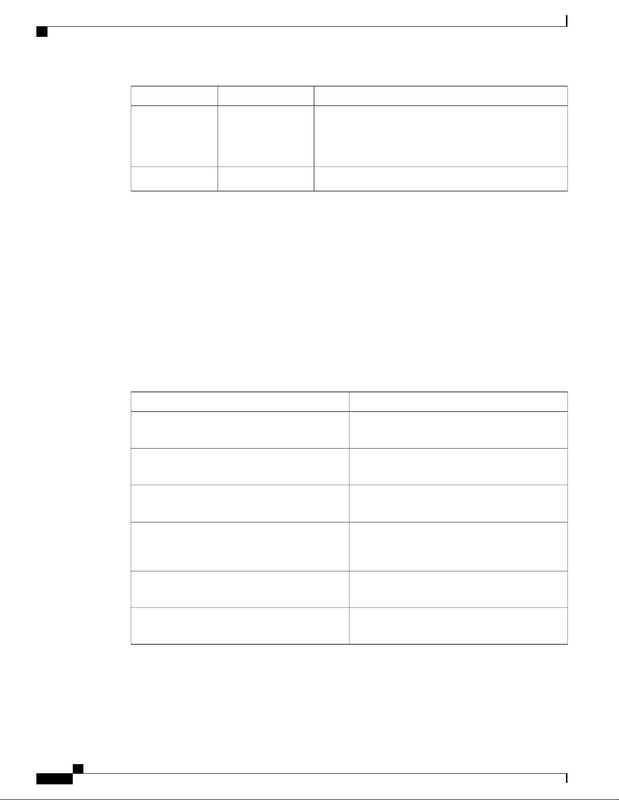
Document Revision History
The following table lists the major changes made to this document for each release.
Change SummaryDateRivision
—
—
—
—
—
July 2017
April 2016
March, 2016
January 6, 2015
Cisco ASR 902 and ASR 902U Aggregation Services Router Hardware Installation Guide
Added information about the Cisco ASR 902U Aggregation
Services Router.
Added information on C37.94 serial interface module.November 2016
Added dust cap information. Added supported patch panel
information. Updated warning statements.
Updated A900-RSP3 and the supported interface modules.
Added blank deflector information. Added ambient temperature
for RSP3.
Updated safety statements. Replaced Cisco Software Advisor
information with Software Research information.
xi
Page 12
Document Audience
Preface
Change SummaryDateRivision
OL-31440-02OL-31440-02
Document Audience
This guide is intended for users who are responsible for installing the Cisco router. It is intended for users
who may not be familiar with the initial configuration and troubleshooting tasks, the relationship among tasks,
or the Cisco IOS software commands necessary to perform particular tasks.
For information on general software features that are also available on other Cisco platforms, see the Cisco
IOS XE technology guide pertaining to that specific software feature.
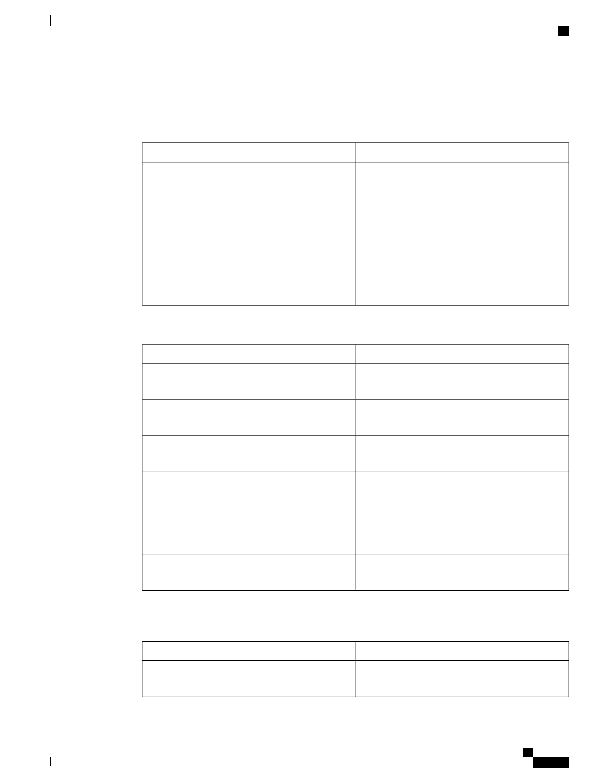
Document Organization
This guide includes the following chapters and appendix:
Added information about the installation of air plenum and
the Cisco Microsoft Windows 7 USB driver, RSP-2 LED
behavior, and new interface modules supported. Updated the
description for Time-of-Day port pinouts.
Initial releaseFebruary 14, 2014OL-31440-01
DescriptionTitle
Chapter 1, Overview
Chapter 2, “Preparing for Installation, on page 39”
Chapter 3, “Installing the Cisco ASR 902 Router, on
page 65”
Chapter 4, “Cisco Router Initial Configuration, on
page 113”
Chapter 5, “Troubleshooting”
Appendix A, “Site Log”
This chapter provides an overview of the Cisco ASR
902 and ASR 902U Routers.
This chapter provides site preparation guidelines for
installing the Cisco ASR 902 and ASR 902U Routers.
This chapter describes the Cisco ASR 902 and ASR
902U Routers and how to install it.
This chapter describes how to start the Cisco ASR
902 and ASR 902U Routers and create an initial
system configuration.
This chapter provides LED and pinout information
for troubleshooting purposes.
This provides a site log for tracking the installation
and maintenance activities of the router.
xii
Cisco ASR 902 and ASR 902U Aggregation Services Router Hardware Installation Guide
Page 13
Preface
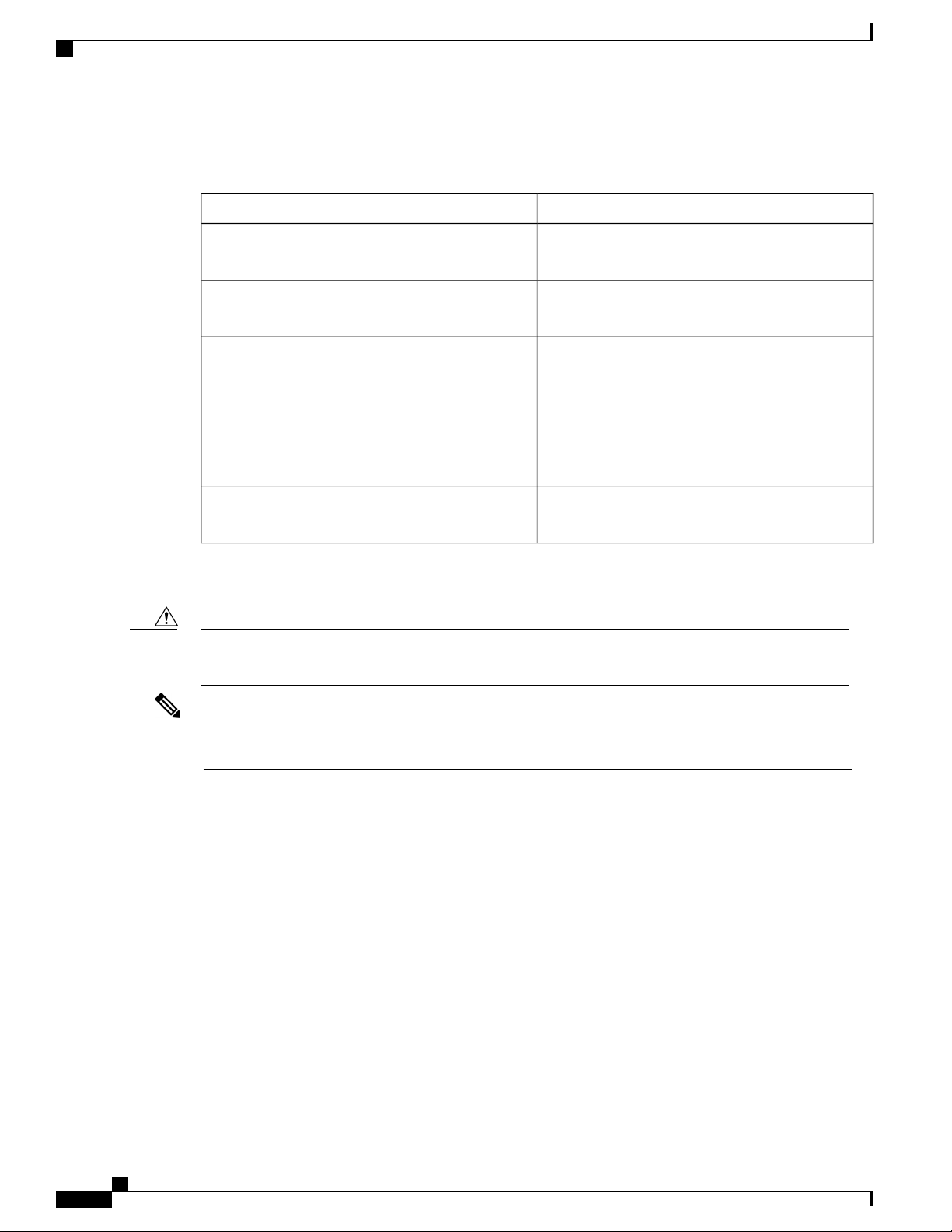
Document Conventions
This documentation uses the following conventions:
Document Conventions
DescriptionConvention
^ or Ctrl
string
Command syntax descriptions use the following conventions:
bold
italics
[x]
The ^ and Ctrl symbols represent the Control key.
For example, the key combination ^D or Ctrl-D
means hold down the Control key while you press
the D key. Keys are indicated in capital letters but are
not case sensitive.
A string is a nonquoted set of characters shown in
italics. For example, when setting an SNMP
community string to public, do not use quotation
marks around the string or the string will include the
quotation marks.
DescriptionConvention
Bold text indicates commands and keywords that you
enter exactly as shown.
Italic text indicates arguments for which you supply
values.
Square brackets enclose an optional element (keyword
or argument).
|
[x | y]
{x | y}
Nested sets of square brackets or braces indicate optional or required choices within optional or required
elements. For example:
[x {y | z}]
Cisco ASR 902 and ASR 902U Aggregation Services Router Hardware Installation Guide
A vertical line indicates a choice within an optional
or required set of keywords or arguments.
Square brackets enclosing keywords or arguments
separated by a vertical line indicate an optional
choice.
Braces enclosing keywords or arguments separated
by a vertical line indicate a required choice.
DescriptionConvention
Braces and a vertical line within square brackets
indicate a required choice within an optional element.
xiii
Page 14
Obtaining Documentation and Submitting a Service Request
Examples use the following conventions:
Preface
DescriptionConvention
Caution
screen
bold screen
< >
Examples of information displayed on the screen are
set in Courier font.
Examples of text that you must enter are set in Courier
bold font.
Angle brackets enclose text that is not printed to the
screen, such as passwords.
!
An exclamation point at the beginning of a line
indicates a comment line. (Exclamation points are
also displayed by the Cisco IOS software for certain
processes.)
[ ]
Square brackets enclose default responses to system
prompts.
The following conventions are used to attract the attention of the reader:
Means reader be careful . In this situation, you might do something that could result in equipment damage
or loss of data.
Note
Means reader take note . Notes contain helpful suggestions or references to materials that may not be
contained in this manual.
Obtaining Documentation and Submitting a Service Request
For information on obtaining documentation, submitting a service request, and gathering additional information,
see the monthly What’s New in Cisco Product Documentation , which also lists all new and revised Cisco
technical documentation, at:
http://www.cisco.com/en/US/docs/general/whatsnew/whatsnew.html
Subscribe to the What’s New in Cisco Product Documentation as a Really Simple Syndication (RSS) feed
and set content to be delivered directly to your desktop using a reader application. The RSS feeds are a free
service and Cisco currently supports RSS version 2.0.
Cisco ASR 902 and ASR 902U Aggregation Services Router Hardware Installation Guide
xiv
Page 15

Overview
CHAPTER 1
Note
The Cisco ASR 902 Router and the Cisco ASR 902U Router are collectively referred to as the Cisco ASR
902 Router in this document. Any differences between the routers are specifically called out.
The Cisco ASR 902 Router is a full-featured aggregation platform designed for cost-effective delivery of
converged mobile and business services. With shallow depth, low power consumption, and an extended
temperature range, this compact 2-rack unit (RU) router provides high service scale and flexible hardware
configuration.
The Cisco ASR 902 Router expands the Cisco service provider product portfolio by providing a rich and
scalable feature set of Layer 2 VPN (L2VPN) and Layer 3 VPN (L3VPN) services in a compact package.
It also supports a variety of software features, including Carrier Ethernet features, Timing over Packet, and
pseudowire.
The Cisco ASR 902 Router is positioned as a preaggregation router in IP Radio Access Network (RAN)
(Global System for Mobile Communications (GSM), Universal Mobile Telecommunications System (UMTS),
Image Maximum (iMAX), Code division multiple access (CDMA), and Long Term Evolution (LTE))
networks or an aggregation router in Carrier Ethernet networks.
Cisco ASR 902 Router Features, page 1
•
Interface Numbering, page 36
•
Regulatory Compliance, page 37
•
Cisco ASR 902 Router Features
The Cisco ASR 902 Router has the following hardware features:
2-RU modular chassis designed for installation in a 300-mm European Telecommunications Standards
•
Institute (ETSI) cabinet
Dedicated slots in the chassis that support the following:
•
Up to four interface modules
◦
One Route Switch Processor (RSP)
◦
Cisco ASR 902 and ASR 902U Aggregation Services Router Hardware Installation Guide
1
Page 16
Cisco ASR 902 Router Features
Network frequency, phase, and time inputs and outputs for network interfaces (SyncE and TDM), BITS,
•
1 PPS or 10 MHz and Timing over Packet (IEEE 1588-2008)
Adjustable front and rear rail mounting locations
•
Front panel access to power supplies, fan tray, RSP, and interface modules
•
Online insertion and removal (OIR) of interface modules, power supplies, and fan tray
•
Discrete status LEDs on power supply, interface module, RSP, and fan tray units
•
Two alarm dry contact inputs (either normally open or normally closed)
•
Environmental-monitoring and environmental-reporting functions
•
LED indicators for critical, major, and minor alarms
•
Side-to-side forced air cooling
•
Up to two DC or two AC or a combination of AC and DC power supply units
◦
One fan tray
◦
Overview
Temperature range of -40 to 149 degrees F (-40 to 65 degrees C) with 550W DC power supply
•
Temperature range of 32 to 122 degrees F (-5 to 55 degrees C) with 550W AC power supply
•
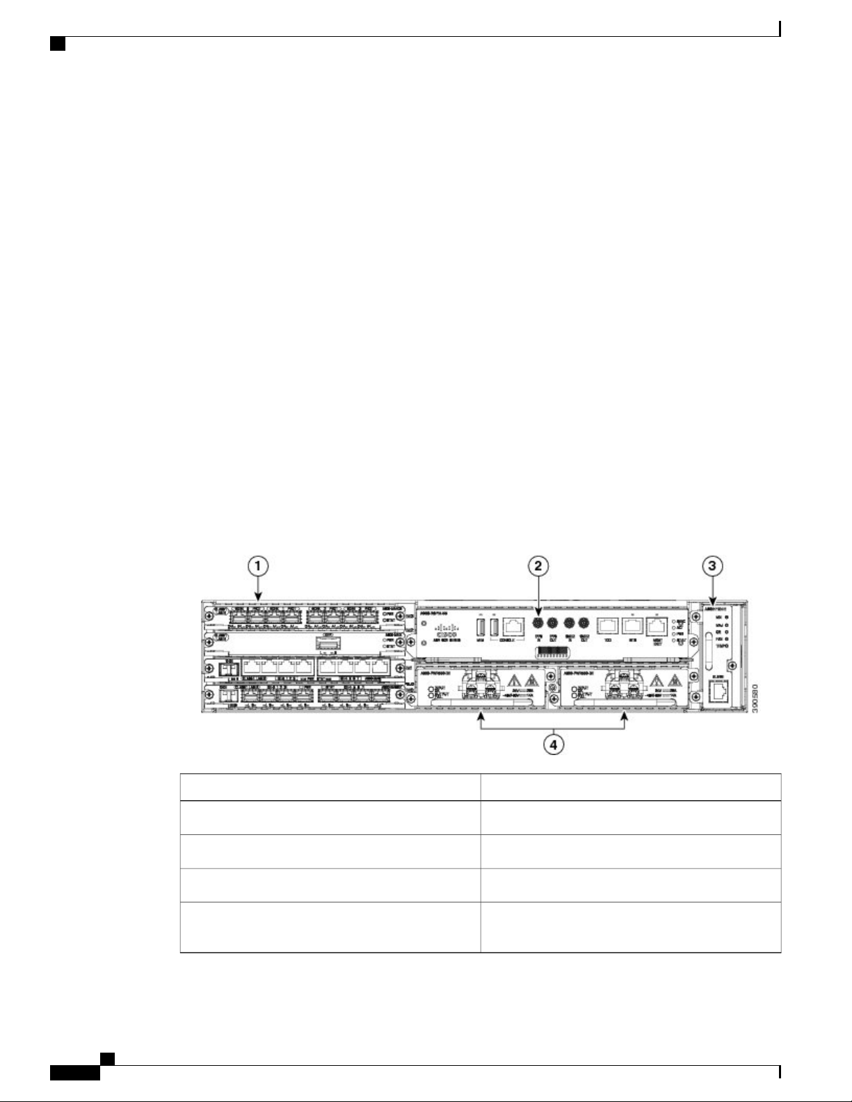
The figure below illustrates the Cisco ASR 902 Router chassis design.
Figure 1: Cisco ASR 902 Router Chassis Design
ComponentLabel
Interface modules1
RSP unit2
Fan tray3
4
Redundant power units (two DC power units are
shown)
Cisco ASR 902 and ASR 902U Aggregation Services Router Hardware Installation Guide
2
Page 17
Overview
System Specifications
The table below summarizes the system specifications and environmental requirements for the Cisco ASR
902 Router.
Table 1: Cisco ASR 902 Router System Specifications
System Specifications
Dimensions (Height x Width x Depth)
Weight
Operating Temperature
3.56 in. x17.44 in. x 10.565 in. (90.424 x 442.976 x
268.351 mm)
Note
This measurement includes handles from the
power supply, fan tray, and interface
modules installed in the chassis.
24.030 pounds (10.9 kg)
Note
This weight includes a power
supply.
The Cisco ASR 902 Router supports the following
temperature ranges with the DC power supply:
• –60 to 4000 meters: –40 to 104ºF (–40 to +
40ºC)
• –60 to 1800 meters: –40 to 149ºF (–40 to +
65ºC)
The Cisco ASR 902 Router supports the following
temperature ranges with the AC power supply:
• –60 to 4000 meters: 32 to 104ºF (0 to 40ºC)
• –60 to 1800 meters: 23 to 140ºF(–5 to 55ºC)
Nonoperating Temperature
Operating Altitude
Nonoperating Vibration
Cisco ASR 902 and ASR 902U Aggregation Services Router Hardware Installation Guide
–40 to 185ºF (–40 to +85ºC) storage temperature
5 to 95% operating noncondensing relative humidityOperating Humidity
–60 to 1800m operating altitude for full operating
temperature range; up to 4000m at up to 40ºC.
4572m storage altitudeNonoperating Altitude
1.0 g from 1.0 to 150 HzVibration
30 G half sine 6 and 11 msShock
Random: 1.15 gRMS 3 to 200 Hz, 30 minutes/axis
Sine: 10 to 500 Hz @ 0.8 G peak/5 sweep cycles/axis
< 68.5 dBa @ 27ºCOperating Acoustics
3
Page 18
Power Supply Features
Power Supply Features
The Cisco ASR 902 Router supports AC and DC power supplies. For more information about installing the
Cisco ASR 902 Router power supplies, see theInstalling the Power Supply section. The power sections provide
more information about the power supply:
Redundancy
The Cisco ASR 902 Router chassis includes a slot for optional redundant power supply. The redundant power
supply option provides a second power supply to ensure that power to the chassis continues uninterrupted if
one power supply fails or input power on one line fails. Redundancy is supported either with identical power
supplies or a combination of AC and DC power supply. The Cisco ASR 902 Router supports current sharing
between the power supplies.
A redundant power supply on the Cisco ASR 902 Router is recommended. Each power supply should be
connected to separate independent power sources to ensure that the router maintains power in the event of a
power interruption caused by an electrical failure, a wiring fault, or a tripped circuit breaker.
Overview
Caution
Dying Gasp
Note
Status LEDs
To comply with IEC 61850-3 (voltage interruptions), redundant power supplies with separately derived
power feeds are required.
The Cisco ASR 902 Router DC power supply supports the Dying Gasp feature, which allows the router to
provide an input power loss notification to the RSP so that the RSP can send appropriate SNMP traps or OAM
messages and update log files on the router. With the DC power supply, the router supports a minimum input
power loss detection time of 2 milliseconds (DC) and continued operation of at least 6 milliseconds (DC)
after the notification.
Continued DC power supply operation may vary for voltages other than +24/–48V.
Dying Gasp is not supported on the ASR 900 RSP3 module with the 1200 W DC power supply.Note
LEDs are also provided on each power supply to indicate the status of the input power and the health of the
power supply. For more information about the LEDs on the Cisco ASR 902 Router, see Troubleshooting.
DC Power Specifications
The Cisco ASR 902 Router uses a +24/-48 DC voltage power supply (with DC voltage tolerance from -19 to
-72 VDC).
Cisco ASR 902 and ASR 902U Aggregation Services Router Hardware Installation Guide
4
Page 19
Overview
Power Supply Features
The power supply provides 550W output power for the system. The power supply is field replaceable, hot
swappable, and operates separately from the fan tray. The power supply contains a front panel with mounting
screws, a handle for insertion and removal, and two status LEDs. No ON/OFF switch is provided.
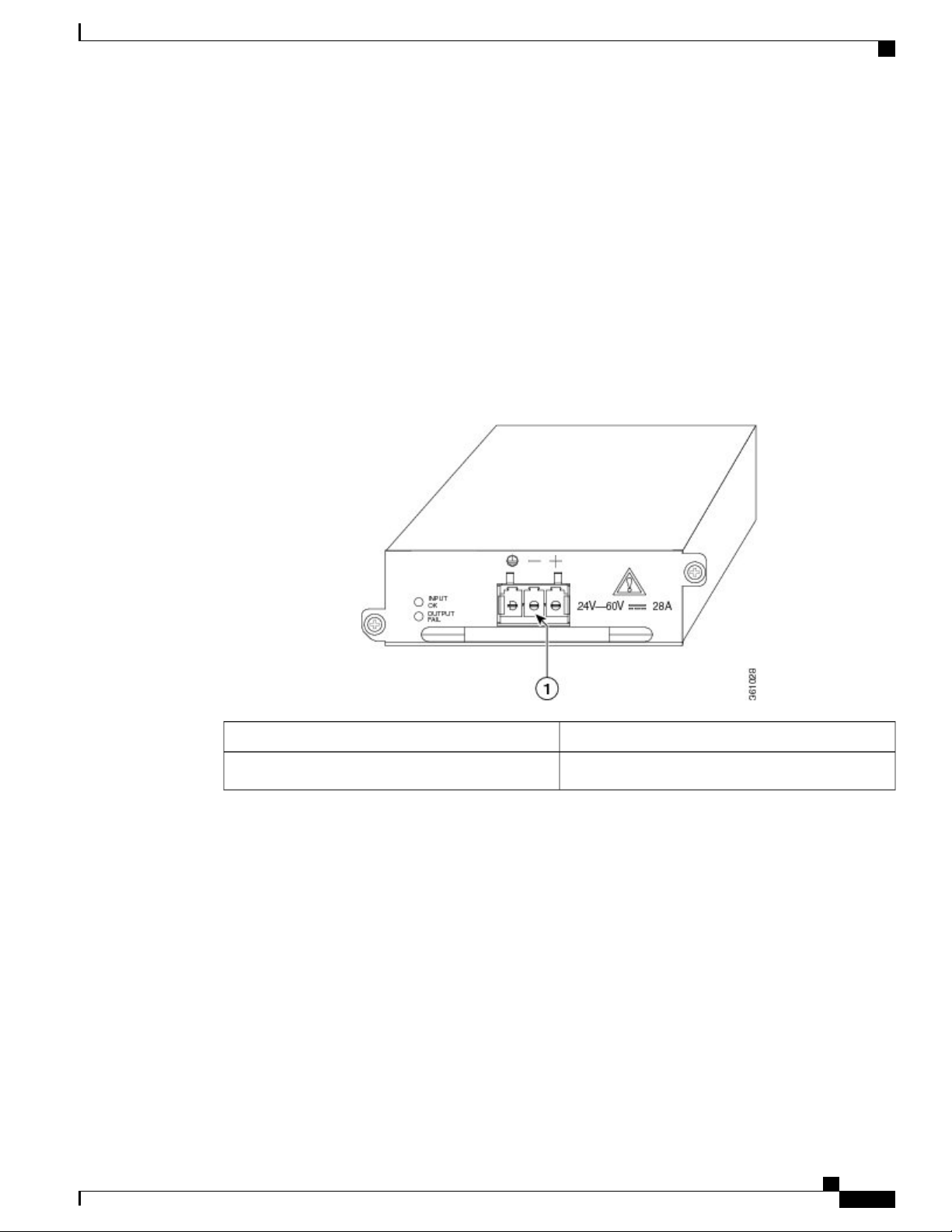
The DC PSU models supported on the router are:
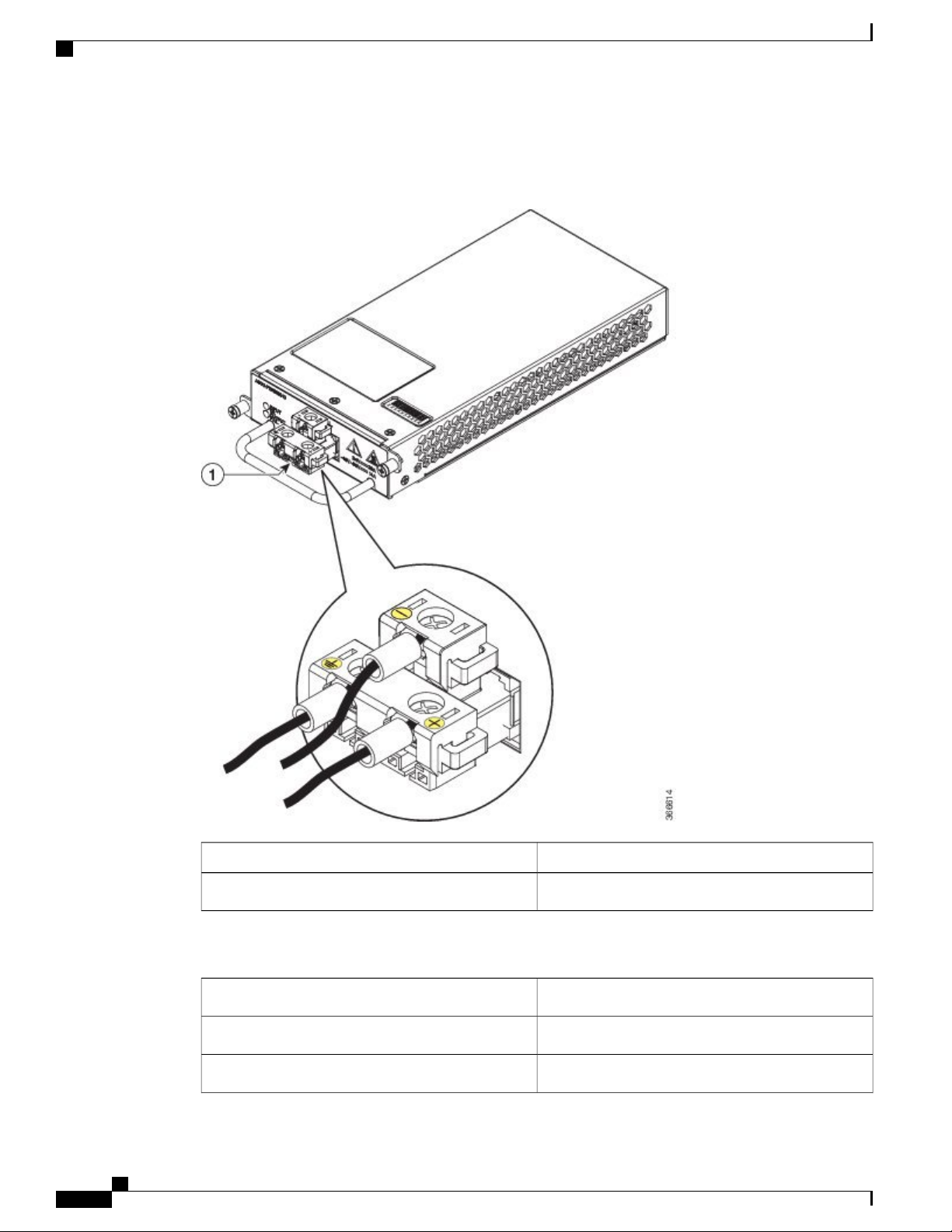
• A900-PWR550-D—Uses an Euro-style three-position terminal block connector ( Figure 1-2 )
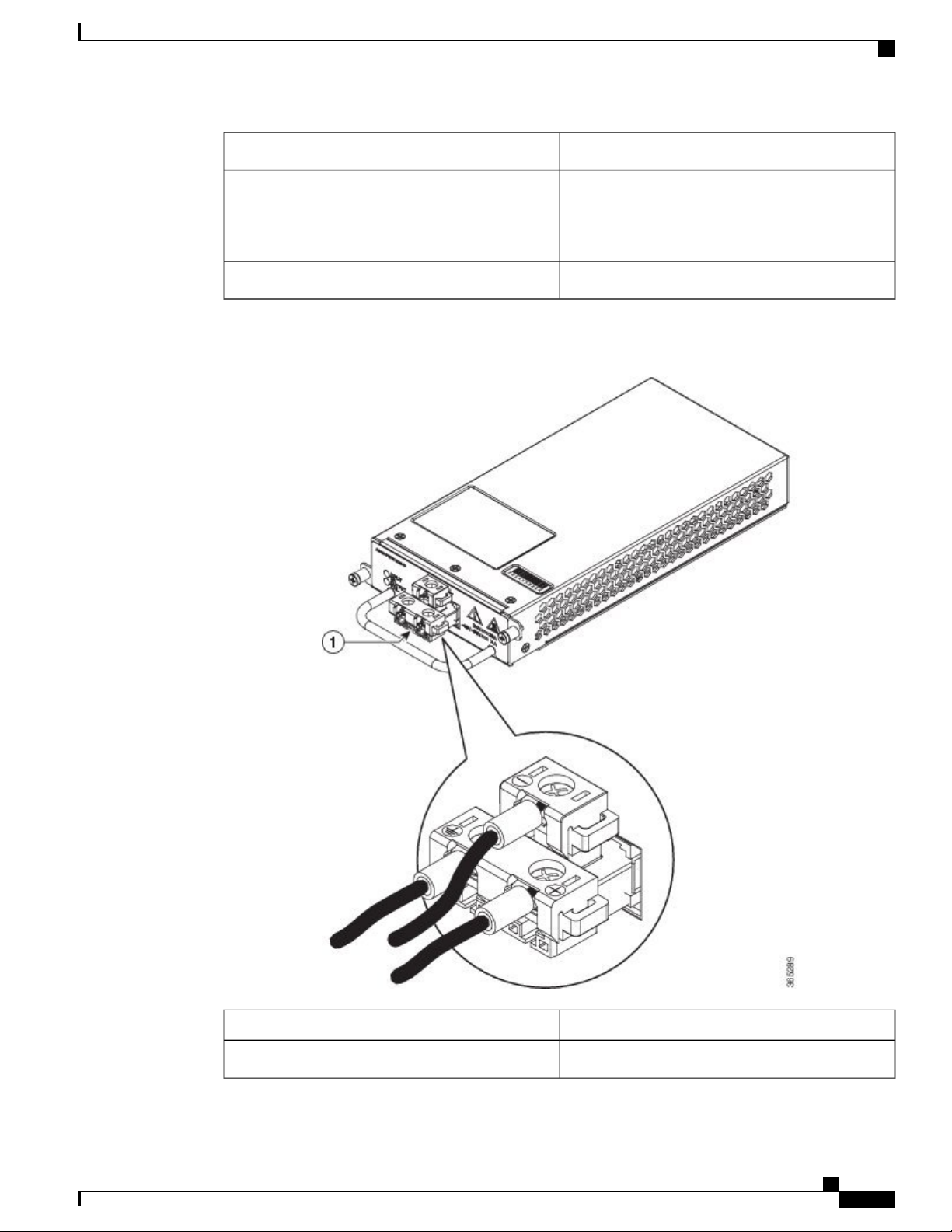
• A900-PWR550-D-E—Uses a T-shaped connector ( Figure 1-3 )
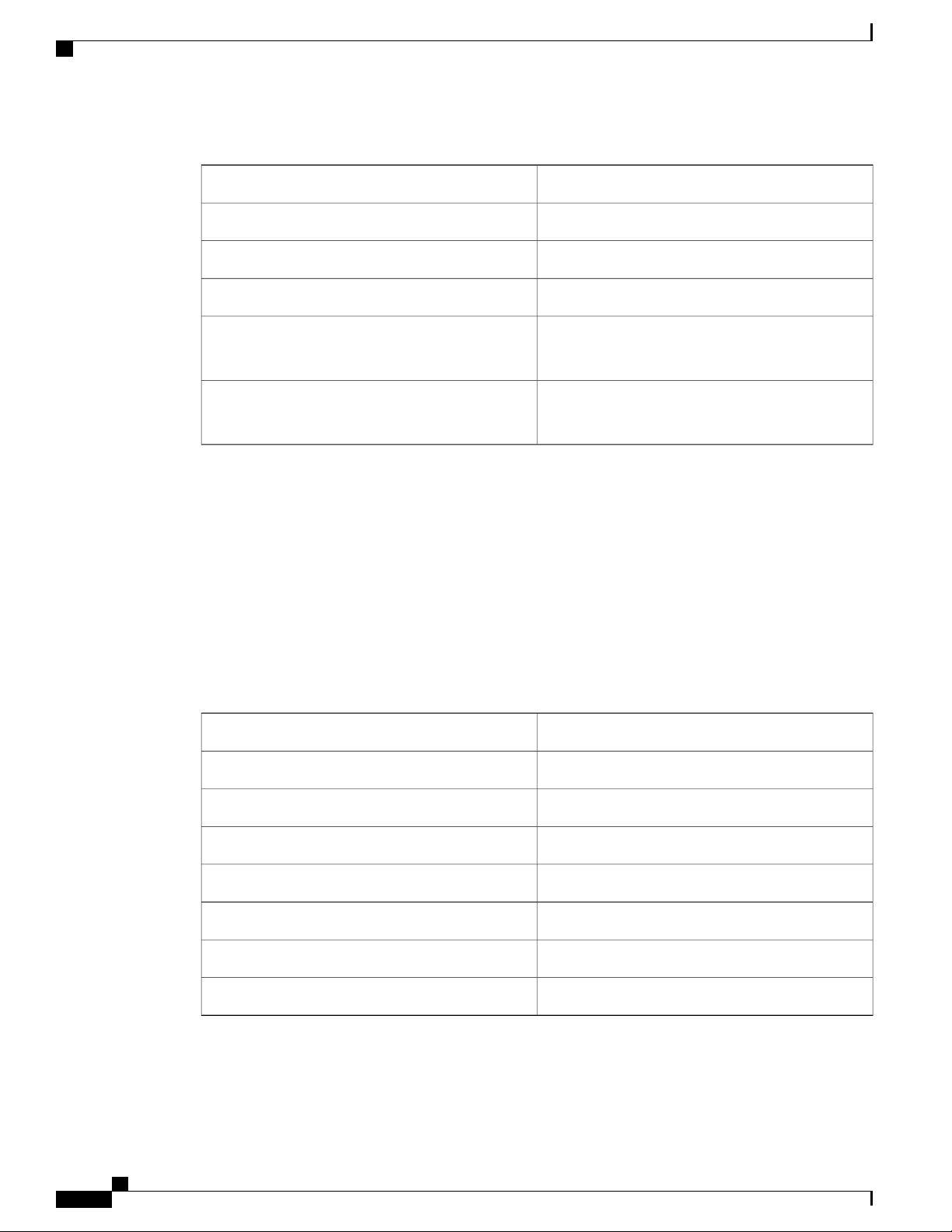
• A900-PWR1200-D—Provides 975 W output power for system 12 V power with the A902-FAN-E
module. As most of the system configurations using A900-RSP3C-200-S RSP modules require power
exceeding 550 W, we recommend using the A900-PWR1200-D power supply with A900-RSP3C-200-S
RSP modules. ( Figure 1-4 )
Figure 2: DC PSU Module (A900-PWR550-D) with Euro-Style Connector
ComponentLabel
Euro-style connector1
Cisco ASR 902 and ASR 902U Aggregation Services Router Hardware Installation Guide
5
Page 20
Power Supply Features
Figure 3: DC PSU (A900-PWR550-D-E) with T-Shaped Connector
Overview
ComponentLabel
T-shaped connector1
Table 2: DC Power Supply Specifications‘(550 W)
A900-PWR550-D, A900-PWR550-D-EPart numbers
Nominal input voltage specification
Input voltage range
Cisco ASR 902 and ASR 902U Aggregation Services Router Hardware Installation Guide
6
+24 VDC/–48 VDC
–19.2 VDC to –72 VDC
Page 21
Overview
Power Supply Features
+12 VDCOutput voltage
Wire gauge for DC input power connections
Figure 4: DC PSU Module (A900-PWR1200-D)
12 AWG minimum for –48/-60 VDC
8 AWG minimum for 24 VDC
Connector accepts 8 AWG maximum
550 WMaximum power output
ComponentLabel
T-shaped connector1
Cisco ASR 902 and ASR 902U Aggregation Services Router Hardware Installation Guide
7
Page 22
Power Supply Features
Table 3: DC Power Supply Specifications (A900-PWR1200-D)
Overview
A900-PWR1200-DPart numbers
48V, GND, -48VNominal input voltage specification
-40.8 VDC to -72 VDCInput voltage range
+12 VDCOutput voltage
Wire gauge for DC input power connections
Maximum power output
AC Power Specifications
The AC PSU models supported on the router are:
• A900-PWR550-A—Provides 550 W power
• A900-PWR1200-D—Provides 1200 W power
The table below summarizes the input power specifications for the Cisco ASR 902 Router AC power supply
units.
Table 4: AC Power Supply Specifications (A900-PWR550-A)
8-10 AWG minimum for -48/-60 VDC.
Connector accepts 8 AWG maximum.
1200 W
975W with A902-FAN-E
A900-PWR550-APart number
115VAC/ 230VACInput power specification
85/264 VACInput voltage
85 VACMinimum input voltage
264 VACMaximum input voltage
12 VDCMinimum output voltage
12.4 VDCMaximum output voltage
550 WMaximum power output
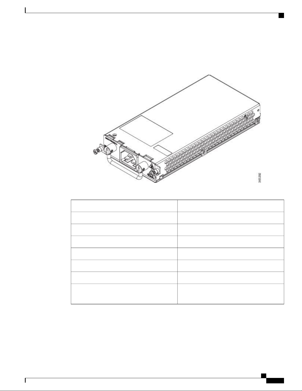
• A900-PWR1200-A—Provides 975 W output power for system 12 V power with the A902-FAN-E
module. As most of the system configurations using A900-RSP3C-200-S RSP modules require power
Cisco ASR 902 and ASR 902U Aggregation Services Router Hardware Installation Guide
8
Page 23
Overview
Fan Tray
exceeding 550 W, we recommend using the A900-PWR1200-A power supply with A900-RSP3C-200-S
RSP modules. ( see the figure below )
Figure 5: Power Supply (A900-PWR1200-A)
Fan Tray
Table 5: AC Power Supply Specifications (A900-PWR1200-A)
Maximum power output
A900-PWR1200-APart number
115VAC/ 230VACInput power specification
85/264 VACInput voltage
85 VACMinimum input voltage
264 VACMaximum input voltage
12VMinimum output voltage
12.4VMaximum output voltage
1200 W
975W with A902-FAN-E
The fan tray has the following hardware features:
Cisco ASR 902 and ASR 902U Aggregation Services Router Hardware Installation Guide
9
Page 24
Fan Tray
It provides side-to-side forced air cooling
•
It provides redundant fans
•
It is field replaceable
•
It contains status LEDs
•
It contains two alarm ports with two external alarm inputs
•
The fan tray modules supported on the router are:
A902-FAN-E ( Figure 1-6 )
•
For more information about air flow guidelines, see the Air Flow Guidelines section . For instructions on how
to install the fan tray, see theInstalling the Fan Tray section. For a summary of the LEDs on the fan tray, see
the LED Summary section .
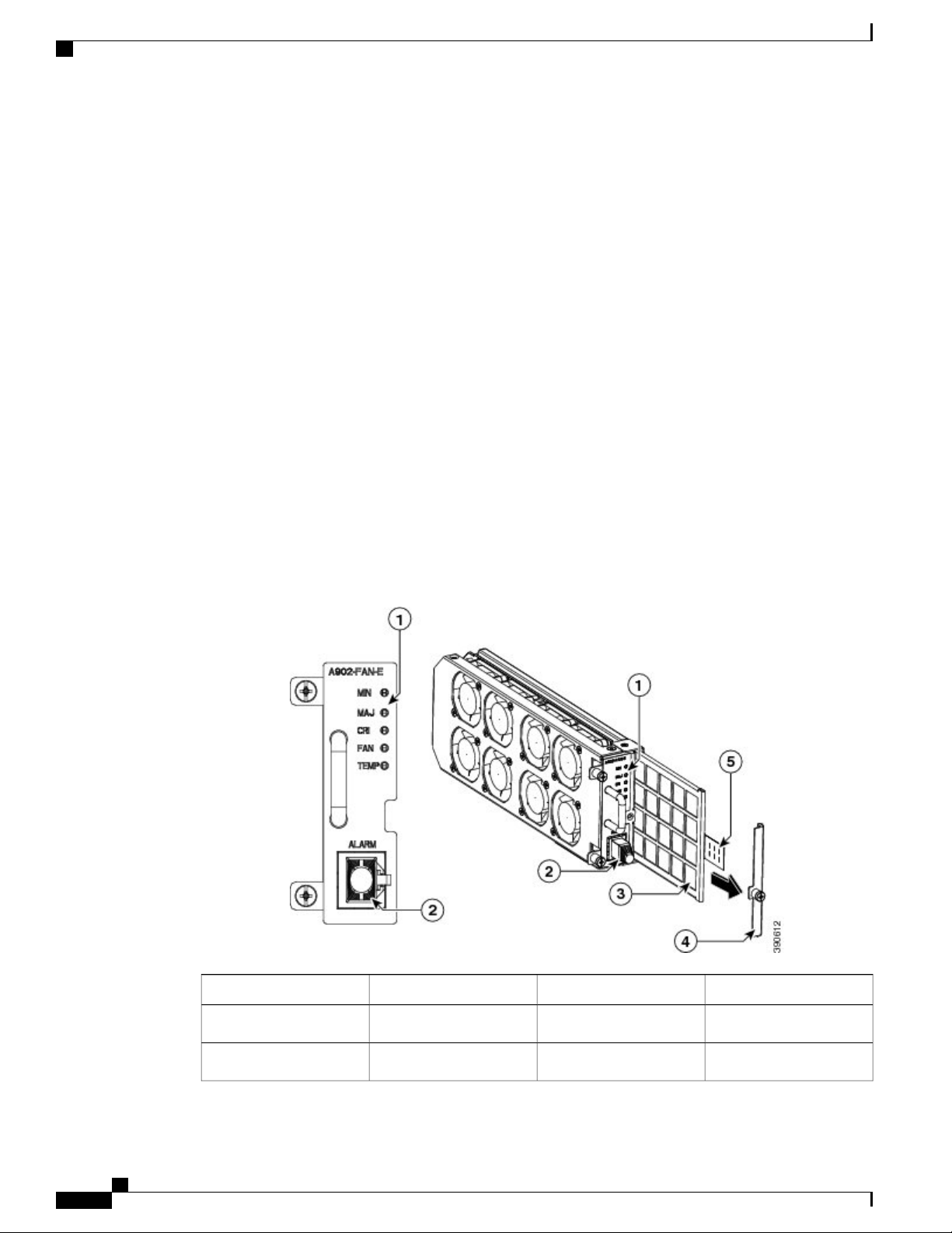
Fan Tray (A902-FAN-E)
Overview
The Cisco ASR 902 Router uses a modular fan tray that is separate from the power supply. The A902-FAN-E
is a fan tray containing eight (40 x 40 x 20 mm) fans and provides sufficient capacity to maintain operations
indefinitely in the event of an individual fan failure. It has a 8-mm fan dust filter that prevents dust from
entering the unit and avoids possible damage to the components. The fan tray is IEC60950-1 compliant.
Figure 6: Cisco ASR 902 Fan Tray with Dust Filter and Dummy Cover (A902-FAN-E)
ComponentLabelComponentLabel
Dummy cover4Label1
Pull tab5Alarm2
Cisco ASR 902 and ASR 902U Aggregation Services Router Hardware Installation Guide
10
Page 25
Overview
Air Plenum
ComponentLabelComponentLabel
Dust Filter (A902-FAN-F)
Air Plenum
Note
Dust filter3
The dust filter (as shown in the figure in Fan Tray (A902-FAN-E section) on the fan tray is a quadrafoam
45PPI filter that is 85 percent dust resistant. A dummy cover (A902-FAN-F-B) secures the dust filter in the
chassis. For installing the fan filter, see theInstalling the Dust Filter section.
Use the pull tab to easily access the filter.Note
Air plenum or air baffle assembly is used to change the air flow pattern of the unit. When the router is installed
with the plenum, the air flow pattern is changed from side-side to front-back. The front-back air flow pattern
provides a rack installation bay with a cool front zone and a hot rear zone. For information about installing
the plenum, see Installing the Router Chassis in the Air Plenum.
When the air plenum and the fan filter are installed in the chassis, the system’s maximum operating
temperature should be 55 degrees Celsius.
——
RSP Modules
To order an air plenum, contact the Sales and Marketing staff at GAW (www.GawTechnology.net) (see
Manufacturers of Equipment Used in Cisco ASR 902 Router).
The Cisco ASR 902 Router is designed to use a single RSP module to handle the data plane, network timing,
and control plane functionalities for the router. The RSP configuration allows you to use Cisco IOS software
to control chassis management, external management, and system status indications on the router.
RSP features include:
Loading software onto processor-based interface modules
•
Packet processing
•
Traffic management, including buffering, queuing, and scheduling, Ethernet MAC functions.
•
Network clocking functions, including phase and time-of-day for Building Integrated Timing Source
•
(BITS), 1 PPS, 10 MHz, and 1588 Precision Time Protocol (PTP) clock references.
Storage of software images, system configuration, Onboard Failure Logging (OBFL), syslog.
•
PTP packet processing, including IEEE 1588-2008 for recovering network timing (frequency, phase,
•
and time) from upstream PTP clocks for generating PTP frequency and phase references as inputs to
Cisco ASR 902 and ASR 902U Aggregation Services Router Hardware Installation Guide
11
Page 26

RSP Modules
Supported RSPs
The Cisco ASR 902 Router supports the following RSPs:
Overview
the Synchronous Equipment Timing Source (SETS), and for distributing them to downstream PTP
clocks.
External management interfaces (RS232 console, management ENET, USB console, USB storage) and
•
system-status LED indicators.
• A900-RSP1A-55—Provides 2-GB of synchronous dynamic random access memory (SDRAM), 5 Mb
of Ternary content-addressable memory (TCAM), 3-Mb buffer table, 576-Mb forwarding memory, and
1,536-Mb packet buffer memory.
• A900-RSP1B-55—Provides 4-GB of SDRAM, 20 Mb of TCAM memory, 144-Mb buffer table, 1152-Mb
forwarding memory, and 1,536-Mb packet buffer memory.
• A900-RSP2A-128—Provides 4-GB double data rate type three (DDR3) memory and 128-Gbps aggregate
throughput.
• A900-RSP2A-64—Provides 4-GB double data rate type three (DDR3) memory and 64-Gbps aggregate
throughput.
• A900-RSP3C-200-S—Provides 8 GB DDR3 memory, 64MB flash memory, 20 Mb of TCAM memory,
8 GB of SDRAM, 200 Gbps throughput, and a USB port for mass storage on the faceplate.
The Cisco ASR 902U Router supports the following RSPs:
• A900U-RSP2A-128—Provides 4-GB double data rate type three (DDR3) memory and 128-Gbps
aggregate throughput.
• A900U-RSP2A-64—Provides 4-GB double data rate type three (DDR3) memory and 64-Gbps aggregate
throughput.
The SD memory card is not field replaceable. Do not try to remove or replace it.Caution
Cisco ASR 902 and ASR 902U Aggregation Services Router Hardware Installation Guide
12
Page 27
Overview
RSP Modules
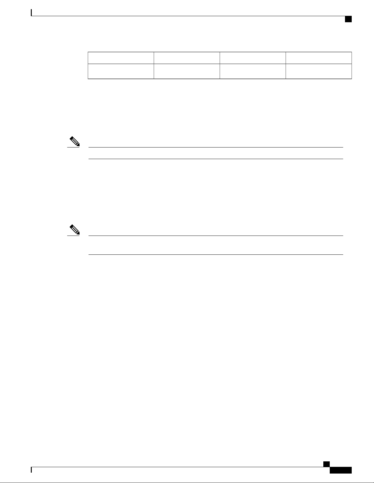
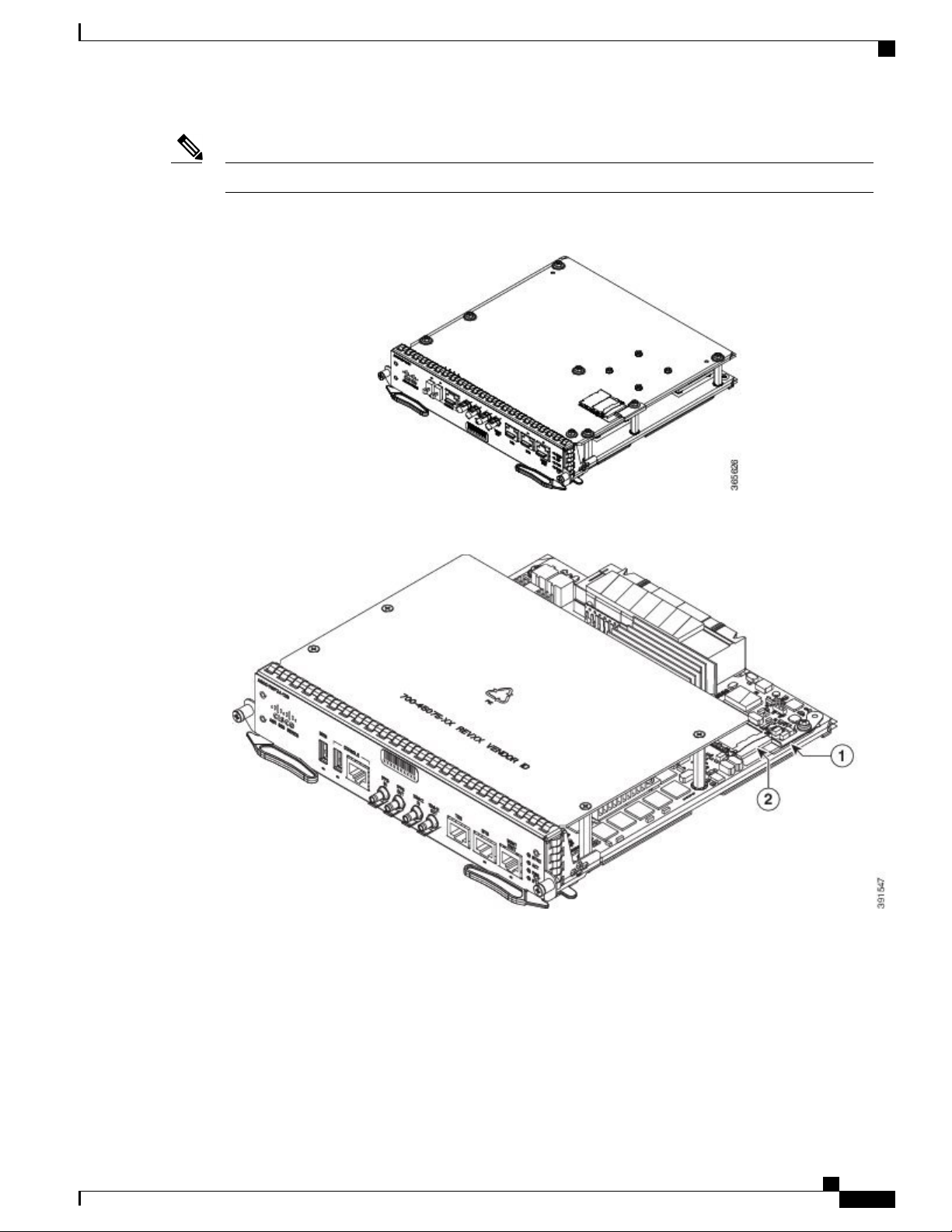
The supported RSPs have different memory capacities, but they have the same interfaces and functionalities.Note
Figure 7: A900-RSP1 Module
Figure 8: A900-RSP2A-128 Module
Figure 9: A900-RSP3C-200-S RSP Module
Cisco ASR 902 and ASR 902U Aggregation Services Router Hardware Installation Guide
13
Page 28
RSP Modules
Overview
A900-RSP1-Supported Interface Modules
Table 6: A900-RSP1-Supported Interface Modules and Part Numbers
A900-RSP1A-55
A900-RSP1B-55
SFP Interface Module
(8x1GE)
RJ45 (Copper) Interface
Module (8x1GE)
Ethernet XFP Interface
Module (1x10GE)
Module
(OC-3) or 1-port
OC12/STM-4 (OC-12)
Interface Module
SlotPart NumberInterface ModuleRSP
AllA900-IMA8S8-port Gigabit Ethernet
A900-IMA8T8-port Gigabit Ethernet
A900-IMA1X1-port 10-Gigabit
A900-IMA16D16-port T1/E1 Interface
A900-IMA4OS4-port OC3/STM-1
A900-IMASER14A/S14-port Serial Interface
Module
Cisco ASR 902 and ASR 902U Aggregation Services Router Hardware Installation Guide
14
Page 29
Overview
A900-RSP2-Supported Interface Modules
Table 7: A900-RSP2-Supported Interface Modules and Part Numbers
RSP Modules
SlotsPart NumbersInterface ModulesRSP
A900-RSP2A-128
A900U-RSP2A-128
SFP Interface Module
(8x1GE)
RJ45 (Copper) Interface
Module (8x1GE)
Ethernet XFP Interface
Module (1x10GE)
Module
(OC-3) or 1-port
OC12/STM-4 (OC-12)
Interface Module
SFP Combo IM—8-port
Gigabit Ethernet (8x1GE)
+
1-port 10-Gigabit
Ethernet (1x10GE)
AllA900-IMA8S8-port Gigabit Ethernet
A900-IMA8T8-port Gigabit Ethernet
A900-IMA1X1-port 10-Gigabit
A900-IMA16D16-port T1/E1 Interface
A900-IMA4OS4-port OC3/STM-1
A900-IMA8S1Z
A900-IMA8T1ZCopper Combo
IM—8-port Gigabit
Ethernet (8x1GE)
+ 1-port 10-Gigabit
Ethernet Interface Module
(1x10GE)
A900-IMA2Z2-port 10 Gigabit Ethernet
Interface Module
(2x10GE)
A900-IMASER14A/S14-port Serial Interface
Module
A900-IMA4C37944-port C37.94 Interface
Module
Cisco ASR 902 and ASR 902U Aggregation Services Router Hardware Installation Guide
15
Page 30
RSP Modules
Overview
SlotsPart NumbersInterface ModulesRSP
A900-RSP2A-64
A900U-RSP2A-64
0-2A900-IMA1X1-port 10 Gigabit Ethernet
XFP Interface Module
(1x10GE)
A900-IMA2Z2-port 10 Gigabit Ethernet
Interface Module
(2x10GE)
A900-IMA4OS4-port OC3/STM-1
(OC-3) or 1-port
OC12/STM-4
(OC-12) Interface Module
0, 2 and 3A900-IMA8S8-port Gigabit Ethernet
SFP Interface Module
(8x1GE)
A900-IMA8T8-port Gigabit Ethernet
RJ45 (Copper) Interface
Module (8x1GE)
A900-IMA16D16-port T1/E1 Interface
Module
Module
Module
Module
Module
Module
A900-IMA32D32-port T1/E1 Interface
A900-IMA8D8-port T1/E1 Interface
A900-IMA6EM6-port E & M Interface
A900-IMASER14A/S14-port Serial Interface
A900-IMA4C37944-port C37.94 Interface
Cisco ASR 902 and ASR 902U Aggregation Services Router Hardware Installation Guide
16
Page 31

Overview
A900-RSP3C-200-S Supported Interface Modules
Table 8: A900-RSP3C-200 Supported Interface Modules and Part Numbers
RSP Modules
RSP Module
A900-RSP3C-200-S
Modules
SFP Interface Module
(8x1GE)
RJ45 (Copper) Interface
Module (8x1GE)
XFP Interface Module
(1x10GE)
SFP Combo IM—8-port
Gigabit Ethernet (8x1GE)
+
1-port 10 Gigabit Ethernet
(1x10GE)
IM—8-port Gigabit
Ethernet (8x1GE)
+ 1-port 10 Gigabit
Ethernet Interface Module
(1x10GE)
SlotPart NumbersSupported Interface
1
A900-IMA8S8-port Gigabit Ethernet
All
A900-IMA8T8-port Gigabit Ethernet
0 and 1A900-IMA1X1-port 10 Gigabit Ethernet
AllA900-IMA8S1Z
A900-IMA8T1ZCopper Combo
A900-IMA2Z2-port 10 Gigabit Ethernet
Interface Module
(2x10GE)
0A900-IMA8Z8-port 10 Gigabit Ethernet
Interface Module
(8x10GE)
A900-IMA2F2-port 40 Gigabit Ethernet
QSFP Interface Module
(2x40GE)
1
There are restrictions using the interface modules in different slots with RSP3 module. Contact Cisco Sales/Support for the valid combinations..
Cisco ASR 902 and ASR 902U Aggregation Services Router Hardware Installation Guide
17
Page 32

RSP Modules
Supported RSP Features
The following are the RSP features supported on the Cisco ASR 902 Router:
Centralized data plane, timing, and control plane functions for the system
•
High-level control of interface modules
•
Management functionalities for the router
•
Control plane (host) CPU and associated memory in which Cisco IOS-XE and platform-control software
•
run
Nonvolatile memory for storage of software images, configurations, and system files
•
Enabling and monitoring the health and presence of fan trays, interface modules, and power supplies
•
Field replacement
•
Network Timing Interfaces
Overview
The RSP supports the following network timing interfaces:
RSP Interfaces
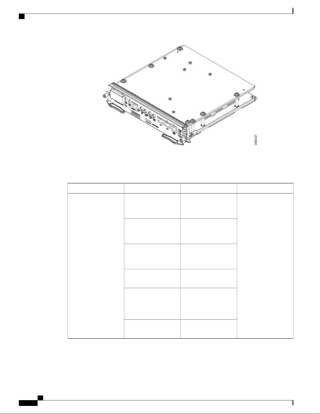
The figure below summarizes the interfaces on an RSP module.
Figure 10: RSP Interfaces Summary
• BITS input/output port—RJ48 jack
• 1 PPS input and output—Mini coax connectors
• 2.048 or 10 MHz input and output—Mini coax connectors
• Time of Day (ToD) —Shielded RJ45 jack
InterfaceLabel
USB memory port1
USB console port2
Cisco ASR 902 and ASR 902U Aggregation Services Router Hardware Installation Guide
18
Page 33

Overview
RSP Modules
InterfaceLabel
Console port3
1-PPS input timing port4
1-PPS output timing port5
10-MHz input timing port6
10-MHz output timing port7
ToD timing port8
BITS timing port9
Ethernet management port10
The A900-RSP2A has the following front panel interfaces. For information on cable pinouts, see Pinouts.
Figure 11: Cisco A900-RSP2A Interface Summary
1 USB Type-A Connector for USB flash (Label = MEM)
•
1 USB Type-A Connector for alternate console port (Label = CONSOLE)
•
RJ45 Connector for Con/Aux (Label = CONSOLE)
•
RJ48 Jack for BITS interface (Label = BITS)
•
RJ48 Jack for Time-of-Day interface (Label= TOD)
•
RJ45 Connector for Con/Aux (Label = MGMT ENET)
•
Cisco ASR 902 and ASR 902U Aggregation Services Router Hardware Installation Guide
19
Page 34

GNSS Module (A900-CM-GNSS)
4 Mini-Coax Connectors (Label = 1PPS IN, 1PPS OUT, 10MHZ IN, 10MHZ OUT)
•
Figure 12: Cisco A900-RSP3C-200-S Interfaces
Overview
InterfaceLabel
GNSS module slot (optional)1
USB memory port2
For more information about installing an RSP, see the RSP Installation section. For more information about
RSP LEDs, see the RSP LEDs section.
GNSS Module (A900-CM-GNSS)
USB console port3
Console port4
1-PPS input timing port5
1-PPS output timing port6
10-MHz input timing port7
10-MHz output timing port8
ToD timing port9
BITS timing port10
Ethernet management port11
The GNSS module is present on the RSP3 modules. It is a pluggable module that allows direct interface with
the external antenna.
To reduce the risk of fire, use only No. 26 AWG or larger telecommunication line cord. Statement 1023Danger
Cisco ASR 902 and ASR 902U Aggregation Services Router Hardware Installation Guide
20
Page 35

Overview
The GNSS module is not hot swappable.Note
GNSS Module RF Input Requirements
The GNSS module requires an active GPS/GNSS antenna with built-in Low-Noise Amplifier (LNA)
•
for optimal performance. The antenna LNA amplifies the received satellite signals for two purposes:
Compensation of losses on the cable
◦
Lifting the signal amplitude in the suitable range for the receiver frontend
◦
The Amplification required is 22dB gain + cable/connector loss + Splitter signal loss.
The recommended range of LNA gain (LNA gain minus all cable and connector losses) at the connector
of the receiver module is 22dB to 30dB with a minimum of 20dB and a maximum of 35dB.
GNSS module provides 5V to the active antenna through the same RF input.
•
GNSS Module (A900-CM-GNSS)
Surge requirement:
•
GNSS modules have built-in ESD protections on all pins, including the RF-input pin. However,
•
additional surge protection may be required if rooftop antennas are being connected, to meet the
regulations and standards for lightning protection in the countries where the end-product is installed.
A lightning protection must be mounted at the place where the antenna cable enters the building.
•
The primary lightning protection must be capable of conducting all potentially dangerous electrical
energy to PE (Protective Earth).
Surge arrestors should support DC-pass and suitable for the GPS frequency range (1.575GHz)
•
with low attenuation.
Antenna Sky visibility:
•
GPS signals can only be received on a direct line of sight between antenna and satellite. The antenna
◦
should see as much as possible from the total sky. For proper timing, minimum of four satellites
should be locked.
Note
The antenna terminal should be earthed at the building entrance in accordance with the
ANSI/NFPA 70, the National Electrical Code (NEC), in particular Section 820.93,
Grounding of Outer Conductive Shield of a Coaxial Cable.
Note
Use a passive splitter if more than one GNSS modules are fed from a single antenna.
•
The splitter should have all the RF ports capable of DC-pass, if the antenna needs to feed power from
GNSS module.
For information on pinout, see GPS Port Pinouts .
Cisco ASR 902 and ASR 902U Aggregation Services Router Hardware Installation Guide
21
Page 36

Interface Modules
Interface Modules
The Cisco ASR 902 Router interface modules are field-replaceable units.
Overview
Note
On RSP-1, Slot 2 Port 0 cannot be used for traffic flow on 8X1-G copper and 8X1-G SFP interface modules.
To identify Slot 2 on a Cisco ASR 902 Router, see the figure in the Interface Numbering, on page 36
section.
In addition to the ports provided on an RSP, the Cisco ASR 902 Router supports the following interface
modules:
Gigabit Ethernet SFP Interface Module
The Gigabit Ethernet Small Form-Factor Pluggable (SFP) interface module provides eight Gigabit Ethernet
SFP modules. The figure below shows the 8-port 1Gigabit Ethernet SFP interface module.
Figure 13: 8 x 1-Gigabit Ethernet SFP Interface Module
For information on supported SFP modules, see Cisco ASR 900 Series Aggregation Services Routers Data
Sheet.
For more information about installing an SFP Gigabit Ethernet module, see the Interface Module Installation.
Cisco ASR 902 and ASR 902U Aggregation Services Router Hardware Installation Guide
22
Page 37

Overview
Gigabit Ethernet RJ45 Interface Module
The Gigabit Ethernet RJ45 interface module provides eight Gigabit Ethernet copper ports. The figure below
shows the interface module.
Figure 14: 8 x 1-Gigabit Ethernet RJ45 (Copper) Interface Module
Interface Modules
For information on supported SFP modules, see Cisco ASR 900 Series Aggregation Services Routers Data
Sheet.
For more information about installing an RJ45 Gigabit Ethernet module, see the Interface Module Installation.
Cisco ASR 902 and ASR 902U Aggregation Services Router Hardware Installation Guide
23
Page 38

Interface Modules
1-Port 10-Gigabit Ethernet XFP Interface Module
The 10-Gigabit Ethernet XFP interface module provides a single port supporting a 10-Gigabit Ethernet XFP
module. The figure below shows the interface module.
Figure 15: 1 x 10-Gigabit Ethernet XFP Interface Module
Overview
For information on supported SFP modules, see Cisco ASR 900 Series Aggregation Services Routers Data
Sheet.
For more information about installing a 10-Gigabit Ethernet XFP module, see the Interface Module Installation.
Cisco ASR 902 and ASR 902U Aggregation Services Router Hardware Installation Guide
24
Page 39

Overview
16-Port T1/E1 Interface Module
The 16-port T1/E1 interface module provides connectivity for up to 16 T1/E1 ports through a 100-pin Amplimite
connector. The T1/E1 interface module requires the use of a patch panel to provide RJ48 (T1) or BNC (E1)
connectors. The figure below shows the interface module.
Figure 16: 16 x T1/E1 Interface Module
Interface Modules
For information on supported SFP modules, see Cisco ASR 900 Series Aggregation Services Routers Data
Sheet.
For more information about installing a T1/E1 interface module, see theInterface Module Installation.
4-port OC3/STM-1 (OC-3) or 1-port OC12/STM-4 (OC-12) Interface Module
The 4-port OC3/STM-1 (OC-3) or 1-port OC12/STM-4 (OC-12) interface module can operate as up to four
STM-1 interfaces.
Note
The optical interface module is designed for both OC-3 and OC-12 traffic. OC-12 is only supported on
the RSP1 module on the router.
Cisco ASR 902 and ASR 902U Aggregation Services Router Hardware Installation Guide
25
Page 40

Interface Modules
Overview
The figure below shows the 4-port OC-3 interface module.
Figure 17: 4-port OC-3 Interface Module
For information on supported SFP modules, see Cisco ASR 900 Series Aggregation Services Routers Data
Sheet.
For more information about installing an optical interface module, see the Interface Module Installation.
For more information about using the LEDs to troubleshoot the Cisco ASR 902 Router, see Troubleshooting.
Cisco ASR 902 and ASR 902U Aggregation Services Router Hardware Installation Guide
26
Page 41

Overview
Interface Modules
8x1 Gigabit Ethernet SFP + 1x10 Gigabit Ethernet SFP+ Combination Interface Module
The 8-port 1 Gigabit Ethernet SFP interface module with the 1-port 10 Gigabit Ethernet interface module is
a high-density combination interface module. This module supports eight 1-Gigabit Ethernet SFP ports and
one 10-Gigabit Ethernet SFP+ port.
Figure 18: 8x1 GE SFP + 1x10 GE SFP+ Interface Module
For information on supported SFP modules, see Cisco ASR 900 Series Aggregation Services Routers Data
Sheet.
For more information about installing the 8X1 GE SFP + 1X10 SFP Gigabit Ethernet module, see the Interface
Module Installation.
Cisco ASR 902 and ASR 902U Aggregation Services Router Hardware Installation Guide
27
Page 42

Overview
Interface Modules
8x1 Gigabit Ethernet RJ45 + 1x10 Gigabit Ethernet SFP+ Combination Interface Module
This 8-port 1 Gigabit Ethernet RJ45 (Copper) interface module with the 1-port 10 Gigabit Ethernet interface
module is a high-density combination interface module. This module supports eight 1 Gigabit Ethernet Copper
ports and one 10 Gigabit Ethernet SFP+ port.
Figure 19: 8x1 GE RJ45 + 1x10 GE SFP+ Interface Module
For information on supported SFP modules, see Cisco ASR 900 Series Aggregation Services Routers Data
Sheet.
For more information about installing the 8X1 GE RJ45 + 1X10 SFP Gigabit Ethernet module, see the Interface
Module Installation.
Cisco ASR 902 and ASR 902U Aggregation Services Router Hardware Installation Guide
28
Page 43

Overview
8-Port 10 Gigabit Ethernet Interface Module (8x10GE)
Figure 20: 8x10 Gigabit Ethernet Interface Module
Interface Modules
The high density 8x10 Gigabit Ethernet interface module supports eight 10 Gigabit Ethernet ports using SFP+
transceivers cages on the faceplate.
It does not support XFP transceivers on the ports.Note
For information on supported SFP modules, see Cisco ASR 900 Series Aggregation Services Routers Data
Sheet.
For more information about installing a 8X10GE module, see the Interface Module Installation.
Cisco ASR 902 and ASR 902U Aggregation Services Router Hardware Installation Guide
29
Page 44

Interface Modules
2-Port 10 Gigabit Ethernet SFP+ Interface Module (2x10 GE)
The 2-port 10 Gigabit Ethernet interface module provides a dual port supporting a 10 Gigabit Ethernet SFP+
and XFP module.
Figure 21: 2-port 10 Gigabit Ethernet Interface Module
Overview
For information on supported SFP modules, see Cisco ASR 900 Series Aggregation Services Routers Data
Sheet.
For more information about installing the 2X10 GE SFP Gigabit Ethernet module, see the Interface Module
Installation.
Cisco ASR 902 and ASR 902U Aggregation Services Router Hardware Installation Guide
30
Page 45

Overview
2-Port 40 Gigabit Ethernet QSFP Interface Module (2x40 GE)
The dual port 40 Gigabit Ethernet interface module supports the 40 Gigabit Ethernet port. The 40G interface
is supported using QSFP+ optics. The figure below shows the interface module.
Figure 22: 2x40 Gigabit Ethernet Interface Module
Interface Modules
For information on supported SFP modules, see Cisco ASR 900 Series Aggregation Services Routers Data
Sheet.
For more information about installing a 2X40GE module, see the Interface Module Installation.
14-Port Serial Interface Module
The Cisco (A900-IMASER14A/S) is a 14-port serial interface module for the router. The Cisco ASR 902
Router module has the following interfaces:
• 12-in-1 Connector (6)—Supports synchronous and asynchronous RS-232 interfaces using EIA/TIA-232
DB-25 connectors.
Cisco ASR 902 and ASR 902U Aggregation Services Router Hardware Installation Guide
31
Page 46

Interface Modules
Overview
• 68-Pin Connector (2)—Supports up to 8 RS-232 interfaces in full or half duplex mode using 4 RS-232
connectors (DB-25, DB-9, or RJ-45).
Figure 23: 14-Port Serial Interface Module
Supported Standards
The 14-port serial interface module supports the following standards:
Table 9: General Standard
IEEE 1613 2009
68-Pin Connector (2)2Captive screws (2)1
Status (STAT) LED412-in-1 Connector (6)3
6Power (PWR) LED5
LEDs—The LEDs are as follows:
• J0–J3 and J4–J7—Indicate the function
of the 68-pin connectors
• J8–J13—Indicate the status of the
12-in-1 connectors
DefinitionStandard
IEEE Standard for Environmental and Testing
Requirements for Communications Networking
Devices in Electric Power Substations
IEC 61850-3
IEC standard specifying general requirements for
substation automation systems (SAS) communications
and related system requirements.
IEC standard for substation environmental conditionsIEC 60870-2-1:1995
Cisco ASR 902 and ASR 902U Aggregation Services Router Hardware Installation Guide
32
Page 47

Overview
Interface Modules
DefinitionStandard
IEC standard for substation environmental conditionsIEC 60870-2-2:1996
IEC 61000-6-5:2001
For more information about installing the module, see the Interface Module Installation.
For information on LEDs, see 14-Port Serial Interface Module LEDs.
For information on cables and pinouts see, Connecting Serial Cables and Serial Interface Modules Pinouts.
6-Port E and M Interface Module
The Cisco A900-IMA6EM is a 6-port Ear and Mouth (E&M) interface module. The interface module provides
the router with connectivity to tele-protection equipments. The front panel of the module consists of:
six port RJ45 connectors
•
two LED that display Power and Status
•
one LED per RJ45 port
•
Figure 24: E and M Interface Module
IEC standard defining immunity for power station
and substation environments
For more information about installing the module, see the Interface Module Installation section.
4-Port C37.94 Interface Module
The Cisco (A900-IMA4C3794) is a 4-port interface module that provides IEEE C37.94-2002 compliant Nx64
kbps optical interface ports to the router. The interfaces support 50/62.5 multimode fiber at 850 nm. The
physical interfaces use 2.5 mm ST connectors.
The front panel of the module consists of:
Cisco ASR 902 and ASR 902U Aggregation Services Router Hardware Installation Guide
33
Page 48

Blank Deflector (A900-IMA-BLNK-DEF)
four ports of IEEE C37.94 interfaces
•
Figure 25: C37.94 Interface Module
Overview
Figure 26: C37.94 Interface Module Front Panel
For more information about installing the module, see the Interface Module Installation section .
Blank Deflector (A900-IMA-BLNK-DEF)
The A900-IMA-BLNK-DEF is a special type of blank filler plate that can be used in empty interface module
slots. In addition to just acting as a filler for the empty slots in the router, this blank deflects additional air
towards the interface modules in the slot below it, thereby enhancing the cooling for the interface module.
The A900-IMA-BLNK-DEF module should not be used in slot 0 in the Cisco ASR 902 Router.Caution
For slot 0, always use the filler blank (A900-IMA-BLANK) when a blank filler needs to be used.
For more information on operating temperature, see Maximum Operating Ambient Temperature Support for
RSP3 Modules .
Maximum Operating Ambient Temperature Support for RSP3 Modules
The router supports multiple fan trays with different cooling capacities. The maximum operating temperature
of the router using the RSP3 modules, depends on the fan tray and the interface modules used in the router.
Cisco ASR 902 and ASR 902U Aggregation Services Router Hardware Installation Guide
34
Page 49

Overview
Temperature Sensor
The table below provides an overview of the operating ambient temperature limits for different interface
modules with A900-RSP3C-200-S in the router.
The temperature range could be further restricted by the optical modules used in the router.Note
Table 10: Operating Temperature for A900-RSP3C-200-S Module
Operating Temperature Limit (°C)Fan TrayInterface Modules
A900-IMA8T
A900-IMA8S
A900-IMA2Z
A900-IMA8T1Z
A900-IMA8S1
A900-IMA8Z
A900-IMA2F
Temperature Sensor
The Cisco ASR 902 Router has a temperature sensor to detect overtemperature conditions inside the chassis.
The overtemperature detection trips at 75°C +/– 5% with the ambient (inlet) trip point at 67°C. This condition
is reported to the processor as an interrupt, and the software takes action to generate the appropriate alarms.
Temperature Sensors on the A900 RSP3 modules
A902-FAN-EA900-IMA1X
–40 to 65
–40 to 50
–40 to 45
The maximum operating temperature of the RSP3 module and the interface modules is less than the maximum
operating temperature of the router. The IOS software decides the appropriate temperature thresholds to
generate warnings, and shuts down the system when abnormally high temperature is detected.
Cisco ASR 902 and ASR 902U Aggregation Services Router Hardware Installation Guide
35
Page 50

Serial Number Label Location
Serial Number Label Location
The figure below shows the serial number label location on the Cisco ASR 902 Router.
Figure 27: Cisco ASR 902 Router Serial Number Location
Overview
Interface Numbering
The Cisco ASR 902 Router chassis includes:
Four interface module slots
•
One RSP module slot
•
Two power supply slots
•
One fan tray slot
•
Each network interface on a Cisco ASR 902 Router is identified by a slot number and a port number.
The figure below shows interface numbering on a Cisco ASR 902 Router.
Figure 28: Cisco ASR 902 Router Slot Numbers
Cisco ASR 902 and ASR 902U Aggregation Services Router Hardware Installation Guide
36
Page 51

Overview
Regulatory Compliance
Slot IdentificationLabel
RSP slot1
Fan tray slot2
Power supply slot 13
Power supply slot 04
Interface module slot 05
Interface module slot 16
Interface module slot 27
Interface module slot 38
The following is an explanation of the interface module slot and port numbering:
The numbering format is interface type slot or interface (port) number. Interface (port) numbers begin
•
at logical 0 for each interface type.
Interface module slots are numbered from bottom to top, with logical interfaces on each module numbered
•
from left to right. Interfaces are hardwired. Therefore, port 0 is always logical interface 0/0, port 1 is
always logical interface 0/1, and so on.
Regulatory Compliance
For regulatory compliance and safety information, see the Product Documentation and Compliance for the
Cisco ASR 900 Series Aggregation Services Routers document.
Cisco ASR 902 and ASR 902U Aggregation Services Router Hardware Installation Guide
37
Page 52

Regulatory Compliance
Overview
Cisco ASR 902 and ASR 902U Aggregation Services Router Hardware Installation Guide
38
Page 53

Preparing for Installation
This chapter describe how to prepare for the installation of the Cisco ASR 902 Router at your site.
Safety Guidelines, page 39
•
Site Planning, page 48
•
Receiving the Cisco ASR 902 Router, page 60
•
Safety Guidelines
Before you begin the installation of the Cisco ASR 902 Router, review the safety guidelines in this chapter
to avoid injuring yourself or damaging the equipment.
In addition, before replacing, configuring, or maintaining the Cisco ASR 902 Router, review the safety
warnings listed in the Product Documentation and Compliance for the Cisco ASR 900 Series Aggregation
Services Routers document.
The following sections describe the safety guidelines for the Cisco ASR 902 Router:
CHAPTER 2
Standard Warning Statements
To see translations of the warnings that appear in this publication, refer to the Product Documentation and
Compliance for the Cisco ASR 900 Series Aggregation Services Routers document.
The appliance must be connected to a grounded outlet. Statement 0414Warning
Warning
To avoid or reduce the risk of personal injury, do not use the product if the product has been exposed to
irregular environmental conditions, if the product has been misused or if parts of the product have been
damaged. Consult qualified service personnel. Never try to service the product yourself. Statement 0416
Cisco ASR 902 and ASR 902U Aggregation Services Router Hardware Installation Guide
39
Page 54

Standard Warning Statements
Preparing for Installation
Warning
Warning
Warning
Warning
To reduce the risk of electric shock, fire or personal injury, do not place power cables in areas where they
may be walked on or damaged by items placed upon or against it. Statement 0417
This product is intended for use in a normal environment based on the standard IEC 60950-1. Do not use
the product in vehicles, on board ships, in aircrafts or in medical applications with physical connection to
the patient, nor in environments with exposure to moisture, dust, vibration or ingress of water. Statement
0418
Do not work on the system or connect or disconnect cables during periods of lightning activity. Statement
1001
Read the installation instructions before connecting the system to the power source. Statement 1004Warning
To prevent bodily injury when mounting or servicing this unit in a rack, you must take special precautions
to ensure that the system remains stable. The following guidelines are provided to ensure your safety:
This unit should be mounted at the bottom of the rack if it is the only unit in the rack. When mounting
this unit in a partially filled rack, load the rack from the bottom to the top with the heaviest component at
the bottom of the rack. If the rack is provided with stabilizing devices, install the stabilizers before mounting
or servicing the unit in the rack. Statement 1006
Warning
Warning
Warning
Warning
This unit is intended for installation in restricted access areas. A restricted access area can be accessed
only through the use of a special tool, lock and key, or other means of security. Statement 1017
If the symbol of suitability with an overlaid cross appears above a port, you must not connect the port to
a public network that follows the European Union standards. Connecting the port to this type of public
network can cause severe injury or damage your router. Statement 1031
Do not use this product near water; for example, near a bath tub, wash bowl, kitchen sink or laundry tub,
in a wet basement, or near a swimming pool. Statement 1035
Never install telephone jacks in wet locations unless the jack is specifically designed for wet locations.
Statement 1036
Cisco ASR 902 and ASR 902U Aggregation Services Router Hardware Installation Guide
40
Page 55

Preparing for Installation
Standard Warning Statements
Warning
Warning
Warning
Warning
Never touch uninsulated telephone wires or terminals unless the telephone line has been disconnected at
the network interface. Statement 1037
Avoid using a telephone (other than a cordless type) during an electrical storm. There may be a remote
risk of electric shock from lightning. Statement 1038
To report a gas leak, do not use a telephone in the vicinity of the leak. Statement 1039Warning
Ultimate disposal of this product should be handled according to all national laws and regulations. Statement
1040
To prevent the system from overheating, do not operate it in an area that exceeds the maximum
recommended ambient temperature of 149°F (65°C). Statement 1047
The chassis should be mounted on a rack that is permanently affixed to the building. Statement 1049Warning
Warning
Warning
Warning
IMPORTANT SAFETY INSTRUCTIONS: This warning symbol means danger. You are in a situation
that could cause bodily injury. Before you work on any equipment, be aware of the hazards involved with
electrical circuitry and be familiar with standard practices for preventing accidents. Use the statement
number provided at the end of each warning to locate its translation in the translated safety warnings that
accompanied this device. Statement 1071
No user-serviceable parts inside. Do not open. Statement 1073Warning
This is a Class A Device and is registered for EMC requirements for industrial use. The seller or buyer
should be aware of this. If this type was sold or purchased by mistake, it should be replaced with a
residential-use type. Statement 294
This is a class A product. In a domestic environment this product may cause radio interference in which
case the user may be required to take adequate measures. Statement 340
Cisco ASR 902 and ASR 902U Aggregation Services Router Hardware Installation Guide
41
Page 56

Safety Guidelines for Personal Safety and Equipment Protection
Preparing for Installation
Warning
This equipment is in compliance with the essential requirements and other relevant provisions of Directive
1999/5/EC. Statement 287
Safety Guidelines for Personal Safety and Equipment Protection
The following guidelines help ensure your safety and protect the equipment. This list does not include all the
potentially hazardous situations. Therefore, you should be on alert.
Before moving the system, always disconnect all the power cords and interface cables.
•
Never assume that power is disconnected from a circuit; always check.
•
Before and after installation, keep the chassis area clear and dust free.
•
Keep tools and assembly components away from walk areas where you or others could trip over them.
•
Do not work alone if potentially hazardous conditions exist.
•
Do not perform any action that creates a potential hazard to people or makes the equipment unsafe.
•
Do not wear loose clothing that may get caught in the chassis.
•
When working under conditions that may be hazardous to your eyes, wear safety glasses.
•
Safety Precautions for Module Installation and Removal
Be sure to observe the following safety precautions when you work on the router.
To see the translations of the warnings that appear in this publication, refer to the Product Documentation and
Compliance for the Cisco ASR 900 Series Aggregation Services Routers document.
Warning
Warning
For connections outside the building where the equipment is installed, the following ports must be connected
through an approved network termination unit with integral circuit protection . Statement 1044
Invisible laser radiation may be emitted from disconnected fibers or connectors. Do not stare into beams
or view directly with optical instruments. Statement 1051
Class 1M laser radiation when open. Do not view directly with optical instruments. Statement 1053Warning
Class 1 (CDRH) and Class 1M (IEC) laser products. Statement 1055Warning
Do not stare into the beam or view it directly with optical instruments. Statement 1011Warning
Cisco ASR 902 and ASR 902U Aggregation Services Router Hardware Installation Guide
42
Page 57

Preparing for Installation
Safety with Electricity
Invisible laser radiation present. Statement 1016Warning
Warning
Hazardous network voltages are present in WAN ports regardless of whether power to the unit is OFF or
ON. To avoid electric shock, use caution when working near WAN ports. When detaching cables, detach
the end away from the unit first. Statement 1026
Warning
Blank faceplates and cover panels serve three important functions: they prevent exposure to hazardous
voltages and currents inside the chassis; they contain electromagnetic interference (EMI) that might disrupt
other equipment; and they direct the flow of cooling air through the chassis. Do not operate the system
unless all cards, faceplates, front covers, and rear covers are in place. Statement 1029
Warning
Hazardous voltage or energy is present on the backplane when the system is operating. Use caution when
servicing. Statement 1034
Warning
Invisible laser radiation may be emitted from disconnected fibers or connectors. Do not stare into beams
or view directly with optical instruments. Statement 1051
Safety with Electricity
Warning
Warning
Warning
Before working on a chassis or working near power supplies, unplug the power cord on AC units; disconnect
the power at the circuit breaker on DC units. Statement 12
Before working on equipment that is connected to power lines, remove jewelry (including rings, necklaces,
and watches). Metal objects will heat up when connected to power and ground and can cause serious burns
or weld the metal object to the terminals. Statement 43
To prevent accidental discharge in the event of a power line cross, route on-premise wiring away from
power cables and off-premise wiring, or use a grounded shield to separate the on-premise wiring from the
power cables and off-premise wiring. A power line cross is an event, such as a lightning strike, that causes
a power surge. Off-premise wiring is designed to withstand power line crosses. On-premise wiring is
protected from power line crosses by a device that provides overcurrent and overvoltage protection.
Nevertheless, if the on-premise wiring is in close proximity to or not shielded from, the off-premise wiring
or power cable during a lightning strike or power surge, the on-premise wiring can carry a dangerous
discharge to the attached interface, equipment, or nearby personnel. Statement 338
Cisco ASR 902 and ASR 902U Aggregation Services Router Hardware Installation Guide
43
Page 58

Safety with Electricity
Preparing for Installation
Warning
Warning
Warning
Warning
High leakage current – earth connection essential before connection to system power supply. Statement
342
Avoid using or servicing any equipment that has outdoor connections during an electrical storm. There
may be a risk of electric shock from lightning. Statement 1088
Before performing any of the following procedures, ensure that power is removed from the DC circuit.
Statement 1003
Read the installation instructions before connecting the system to the power source. Statement 1004Warning
This product relies on the building’s installation for short-circuit (overcurrent) protection. Ensure that the
protective device is rated: For a -48/-60 VDC installation, the wire shall be 12 AWG minimum with a 20
A branch circuit breaker. For a 24 VDC installation, the wire shall be 8 AWG minimum with a 40 A
branch circuit breaker. Statement 1005
Warning
Warning
Warning
Warning
This product relies on the building’s installation for short-circuit (overcurrent) protection. For an AC
installation, ensure that the branch circuit breaker is rated a maximum 20A. Statement 1005
There is the danger of explosion if the battery is replaced incorrectly. Replace the battery only with the
same or equivalent type recommended by the manufacturer. Dispose of used batteries according to the
manufacturer’s instructions. Statement 1015
This unit is intended for installation in restricted access areas. A restricted access area can be accessed
only through the use of a special tool, lock and key, or other means of security. Statement 1017
Take care when connecting units to the supply circuit so that wiring is not overloaded. Statement 1018Warning
The plug-socket combination must be accessible at all times, because it serves as the main disconnecting
device. Statement 1019
Cisco ASR 902 and ASR 902U Aggregation Services Router Hardware Installation Guide
44
Page 59

Preparing for Installation
Safety with Electricity
Warning
Warning
Warning
Warning
To avoid electric shock, do not connect safety extra-low voltage (SELV) circuits to telephone-network
voltage (TNV) circuits. LAN ports contain SELV circuits, and WAN ports contain TNV circuits. Some
LAN and WAN ports both use RJ45 connectors. Use caution when connecting cables. Statement 1021
A readily accessible two-poled disconnect device must be incorporated in the fixed wiring. Statement
1022
To reduce the risk of fire, use only 26 AWG or larger telecommunication line cord. Statement 1023Warning
This equipment must be grounded. Never defeat the ground conductor or operate the equipment in the
absence of a suitably installed ground conductor. Contact the appropriate electrical inspection authority
or an electrician if you are uncertain that suitable grounding is available. Statement 1024
Use copper conductors only. Statement 1025Warning
Hazardous network voltages are present in WAN ports regardless of whether power to the unit is OFF or
ON. To avoid electric shock, use caution when working near WAN ports. When detaching cables, detach
the end away from the unit first. Statement 1026
Warning
Warning
Warning
Warning
This unit might have more than one power supply connection. All connections must be removed to
de-energize the unit. Statement 1028
To prevent personal injury or damage to the chassis, never attempt to lift or tilt the chassis using the
handles on modules (such as power supplies, fans, or cards); these types of handles are not designed to
support the weight of the unit. Statement 1032
Connect the unit only to DC power source that complies with the safety extra-low voltage (SELV)
requirements in IEC 60950 based safety standards. Statement 1033
Do not use this product near water; for example, near a bath tub, wash bowl, kitchen sink or laundry tub,
in a wet basement, or near a swimming pool. Statement 1035
Cisco ASR 902 and ASR 902U Aggregation Services Router Hardware Installation Guide
45
Page 60

Safety with Electricity
Preparing for Installation
Warning
Warning
Warning
Warning
Never install telephone jacks in wet locations unless the jack is specifically designed for wet locations.
Statement 1036
Before opening the unit, disconnect the telephone-network cables to avoid contact with telephone-network
voltages. Statement 1041
This product requires short-circuit (overturned) protection, to be provided as part of the building installation.
Install only in accordance with national and local wiring regulations. Statement 1045
When installing or replacing the unit, the ground connection must always be made first and When you
connect or disconnect the power and/or alarm connector with power applied, an electrical arc can occur.
This could cause an explosion in hazardous area installations. Be sure that all power is removed from the
switch and any other circuits. Be sure that power cannot be accidentally turned on or verify that the area
is nonhazardous before proceeding. Statement 1058
Installation of the equipment must comply with local and national electrical codes. Statement 1074Warning
Warning
Warning
If you connect or disconnect the console cable with power applied to the switch or any device on the
network, an electrical arc can occur. This could cause an explosion in hazardous location installations. Be
sure that power is removed or the area is nonhazardous before proceeding. Statement 1080
Hazardous voltage or energy may be present on power terminals. Always replace cover when terminals
are not in service. Be sure uninsulated conductors are not accessible when cover is in place. Statement
1086
When working on equipment powered by electricity, follow these guidelines:
• Locate the room’s emergency power-off switch. If an electrical accident occurs, you will be able to
quickly turn off the power.
Before starting work on the system, turn off the DC main circuit breaker and disconnect the power
•
terminal block cable.
Before doing the following, disconnect all power:
•
Working on or near power supplies
◦
Installing or removing a router chassis or network processor module
◦
Performing most hardware upgrades
◦
Never install equipment that appears damaged.
•
Cisco ASR 902 and ASR 902U Aggregation Services Router Hardware Installation Guide
46
Page 61

Preparing for Installation
Power Supply Considerations
Carefully examine your work area for possible hazards, such as moist floors, ungrounded power extension
•
cables, and missing safety grounds.
Never assume that power is disconnected from a circuit; always check.
•
Never perform any action that creates a potential hazard to people or makes the equipment unsafe.
•
If an electrical accident occurs, proceed as follows:
•
Use caution, and do not become a victim yourself.
◦
Turn off power to the router.
◦
If possible, send another person to get medical aid. Otherwise, determine the condition of the
◦
victim, and then call for help.
Determine whether the person needs rescue breathing or external cardiac compressions; then take
◦
appropriate action.
In addition, use the following guidelines when working with any equipment that is disconnected from a power
source, but still connected to telephone wiring or network cabling:
Never install telephone wiring during a lightning storm.
•
Never install telephone jacks in wet locations unless the jack is specifically designed for it.
•
Never touch uninsulated telephone wires or terminals unless the telephone line is disconnected at the
•
network interface.
When installing or modifying telephone lines, use caution.
•
Power Supply Considerations
Check the power at your site to ensure that you are receiving clean power (free of spikes and noise). Install a
power conditioner, if necessary.
This equipment has been designed for connection to TN and IT power systems. Statement 1007Warning
Preventing ESD Damage
Warning
This equipment needs to be grounded. Use a green and yellow 6 AWG ground wire to connect the host
to earth ground during normal use. Statement 383
Electrostatic discharge (ESD) can damage equipment and impair electrical circuitry. ESD may occur when
electronic printed circuit cards are improperly handled and can cause complete or intermittent failures. When
removing and replacing modules, always follow ESD prevention procedures:
Ensure that the router chassis is electrically connected to earth ground.
•
Cisco ASR 902 and ASR 902U Aggregation Services Router Hardware Installation Guide
47
Page 62

Site Planning
Preparing for Installation
Wear an ESD-preventive wrist strap, ensuring that it makes good skin contact. To channel unwanted
•
ESD voltages safely to ground, connect the clip to an unpainted surface of the chassis frame. To guard
against ESD damage and shocks, the wrist strap and cord must operate effectively.
If no wrist strap is available, ground yourself by touching a metal part of the chassis.
•
When installing a component, use any available ejector levers or captive installation screws to properly
•
seat the bus connectors in the backplane or midplane. These devices prevent accidental removal, provide
proper grounding for the system, and help to ensure that bus connectors are properly seated.
When removing a component, use available ejector levers or captive installation screws, if any, to release
•
the bus connectors from the backplane or midplane.
Handle components by their handles or edges only; do not touch the printed circuit boards or connectors.
•
Place a removed component board side up on an antistatic surface or in a static-shielding container. If
•
you plan to return the component to the factory, immediately place it in a static-shielding container.
Avoid contact between the printed circuit boards and clothing. The wrist strap only protects components
•
from ESD voltages on the body; ESD voltages on clothing can still cause damage.
Never attempt to remove the printed circuit board from the metal carrier.
•
Note
For the safety of your equipment, periodically check the resistance value of the antistatic wrist strap. It
should be between 1 and 10 Mohm.
Site Planning
The following sections describe how to plan for the installation of the Cisco ASR 902 Router:
General Precautions
Observe the following general precautions when using and working with your Cisco ASR 902 Router system:
Keep your system components away from radiators and heat sources and do not block cooling vents.
•
Do not spill food or liquids on your system components and never operate the product in a wet
•
environment.
Do not push any objects into the openings of your system components. Doing so can cause fire or electric
•
shock by shorting out interior components.
Position system cables and power supply cable carefully. Route system cables and the power supply
•
cable and plug so that they are not stepped on or tripped over. Be sure that nothing else rests on your
system component cables or power cable.
Do not modify power cables or plugs. Consult a licensed electrician or your power company for site
•
modifications. Always follow your local and national wiring rules.
If you turn off your system, wait at least 30 seconds before turning it on again to avoid damage of system
•
components.
Cisco ASR 902 and ASR 902U Aggregation Services Router Hardware Installation Guide
48
Page 63

Preparing for Installation
Site Planning Checklist
Use the following checklist to perform and account for all the site planning tasks described in this chapter:
The site meets the environmental requirements.
•
• The site’s air conditioning system can compensate for the heat dissipation of the Cisco ASR 902 Router.
The floor space that the Cisco ASR 902 Router occupies can support the weight of the system.
•
Electrical service to the site complies with the requirements.
•
The electrical circuit servicing the Cisco ASR 902 Router complies with the requirements.
•
Consideration has been given to the console port wiring and limitations of the cabling involved, according
•
to TIA/EIA-232F.
The Cisco ASR 902 Router Ethernet cabling distances are within the prescribed limitations.
•
The equipment rack in which you plan to install the Cisco ASR 902 Router complies with prescribed
•
requirements.
Site Planning Checklist
When selecting the location of the rack, careful consideration must be given to safety, ease of maintenance,
•
and proper airflow.
Site Selection Guidelines
The Cisco ASR 902 Router requires specific environmental operating conditions. Temperature, humidity,
altitude, and vibration can affect the performance and reliability of the router. The following sections provide
specific information to help you plan for the proper operating environment.
The Cisco ASR 902 Router is designed to meet the industry EMC, safety, and environmental standards
described in the Product Documentation and Compliance for the Cisco ASR 900 Series Aggregation Services
Routers document.
Environmental Requirements
The Cisco ASR 902 Router is Telcordia GR-3108-CORE Class-1/GR-63-Core Indoor compliant. Environmental
monitoring of the Cisco ASR 902 Router protects the system and components from damage caused by excessive
voltage and temperature conditions. To ensure normal operation and avoid unnecessary maintenance, plan
and prepare your site configuration before installation. After installation, make sure that the site maintains
the environmental characteristics described in the System Specifications.
For an outside plant installation (cell site cabinet, hut etc.), it is required that the Cisco ASR 902 Router be
protected against airborne contaminants, dust, moisture, insects, pests, corrosive gases, polluted air or other
reactive elements present in the outside air. To achieve this level of protection, we recommend that the unit
be installed in a fully sealed enclosure or cabinet. Examples of such cabinets include IP65 cabinets with heat
exchanger complying with Telecordia GR487. Temperature must be maintained within –40ºC to 65ºC.
Physical Characteristics
Be familiar with the physical characteristics of the Cisco ASR 902 Router to assist you in placing the system
in the proper location. For more information, see the System Specifications.
Cisco ASR 902 and ASR 902U Aggregation Services Router Hardware Installation Guide
49
Page 64

Air Flow Guidelines
Air Flow Guidelines
Cool air is circulated through the Cisco ASR 902 Router by a fan tray located along the right side of the router.
The fan tray maintains acceptable operating temperatures for the internal components by drawing in cool air
through the vents, and circulating the air through the chassis.
The following guidelines will help you plan your equipment rack configuration:
• For horizontal mounting—Air flow is side to side and right to left, as shown in the figure below . To
ensure adequate air flow through the equipment rack, we recommend that you maintain a clearance of
at least 80 mm on each side of the rack at all times.
Figure 29: Cisco ASR 902 Router Chassis Air Flow - Horizontal Mounting
Preparing for Installation
• For vertical mounting—Air flow is bottom to top, as shown in the figure below . To ensure adequate
air flow through the equipment rack, we recommend that you maintain a clearance of at least 80 mm
(X) on top and 100 mm (Y) at bottom of the rack at all times.
Cisco ASR 902 and ASR 902U Aggregation Services Router Hardware Installation Guide
50
Page 65

Preparing for Installation
Air Flow Guidelines
Caution
When mounting the router vertically, ensure that the fan tray is at the bottom to ensure bottom-to-top air
flow.
Figure 30: Cisco ASR 902 Router Chassis Air Flow - Vertical Mounting
If airflow through the equipment rack and the routers that occupy it is blocked or restricted, or if the
•
ambient air being drawn into the rack is too warm, an overtemperature condition may occur within the
rack and the routers that occupy it.
The site should also be as dust-free as possible. Dust tends to clog the router fans, reducing the flow of
•
cooling air through the equipment rack and the routers that occupy it, thus increasing the risk of an
overtemperature condition.
Enclosed racks must have adequate ventilation. Ensure that the rack is not congested because each router
•
generates heat. An enclosed rack should have louvered sides and a fan to provide cooling air. Heat that
is generated by the equipment near the bottom of the rack can be drawn upward into the intake ports of
the equipment above.
Cisco ASR 902 and ASR 902U Aggregation Services Router Hardware Installation Guide
51
Page 66

Floor Loading Considerations
When mounting a chassis in an open rack, ensure that the rack frame does not block the side intakes and
•
the exhaust fans.
When rack-installed equipment fails, especially equipment in an enclosed rack, try operating the equipment
•
by itself, if possible. Power off all the other equipment in the rack (and in adjacent racks) to give the
router maximum cooling air and clean power.
Avoid locating the Cisco ASR 902 Router in a location in which the chassis air intake vents may draw
•
in the exhaust air from adjacent equipment. Consider how the air flows through the router; the airflow
direction is side to side, with ambient air drawn in from the vents located on the front right of the chassis.
Air Flow Guidelines for Enclosed Rack Installation
To install a Cisco ASR 902 Router in a 4-post enclosed cabinet, the front and rear doors of the cabinet must
be removed or be perforated with a minimum of 65% open area (70% for ETSI 800-mm racks).
If you are mounting the chassis in a 4-post enclosed cabinet, ensure that you have a minimum of 6 inches
(15.24 cm) of clearance on each side of the chassis.
Preparing for Installation
Floor Loading Considerations
Ensure that the floor under the rack supporting the Cisco ASR 902 Routers is capable of supporting the
combined weight of the rack and all the other installed equipment.
To assess the weight of a fully configured Cisco ASR 902 Router, refer to the System Specifications.
For additional information about floor loading requirements, see the GR-63-CORE, Network Equipment
Building System (NEBS) Requirements: Physical Protection document.
Site Power Guidelines
The Cisco ASR 902 Router has specific power and electrical wiring requirements. Adhering to these
requirements ensures reliable operation of the system. Follow these precautions and recommendations when
planning your site power for the Cisco ASR 902 Router:
The redundant power option provides a second, identical power supply to ensure that power to the chassis
•
continues uninterrupted if one power supply fails or input power on one line fails.
In systems configured with the redundant power option, connect each of the two power supplies to
•
separate independent power source. If you fail to do this, your system might be susceptible to total power
failure due to a fault in the external wiring or a tripped circuit breaker.
To prevent a loss of input power, be sure that the total maximum load on each circuit supplying the
•
power supplies is within the current ratings of the wiring and the breakers.
Check the power at your site before installation, and periodically after installation to ensure that you are
•
receiving clean power. Install a power conditioner, if necessary.
Provide proper grounding to avoid personal injury and damage to the equipment due to lightning striking
•
power lines or due to power surges. The chassis ground must be attached to a central office or other
interior ground system.
Cisco ASR 902 and ASR 902U Aggregation Services Router Hardware Installation Guide
52
Page 67

Preparing for Installation
Site Power Guidelines
Caution
Note
This product requires short-circuit (overcurrent) protection to be provided as part of the building installation.
Install only in accordance with national and local wiring regulations.
The Cisco ASR 902 Router installation must comply with all the applicable codes, and is approved for
use with copper conductors only. The ground bond-fastening hardware should be of compatible material
and preclude loosening, deterioration, and electrochemical corrosion of hardware and joined material.
Attachment of the chassis ground to a central office or other interior ground system must be made with a
6-AWG gauge wire copper ground conductor at a minimum.
The table below lists the maximum power draw of the Cisco ASR 902 Router chassis and its configurable
hardware components. The maximum power-draw values are not affected by whether the router chassis
contains 1 or 2 power supplies and if AC or DC.
Table 11: Maximum Power Draw For Cisco ASR 902 Router Chassis
Maximum Power Draw ValueHardware Component
170 WRouter chassis with 2 power supplies, 1 fan tray, and
1 RSP1A
180 WRouter chassis with 2 power supplies, 1 fan tray, and
1 RSP1B
70 WA900-RSP2A-64
interface module)
interface module)
module)
interface module)
GE interface module
100 WA900-RSP2A-128
160 WA900-RSP3-200-S
13.0 WA900-IMA1X (1-port 10 Gigabit Ethernet XFP
17.5 WA900-IMA8T (8-port 1 Gigabit Ethernet RJ45
17.5 WA900-IMA8S (8-port 1 Gigabit Ethernet SFP interface
14.5 WA900-IMA16D (16-port T1/E1 interface module)
26 WA900-IMA4OS (4-Port OC3 interface module)
29 WA900-IMA8S1Z (8-port 1GE SFP + 1-port 10 GE
27 WA900-IMA8T1Z (8-port 1GE RJ-45 Copper + 1 10
Cisco ASR 902 and ASR 902U Aggregation Services Router Hardware Installation Guide
53
Page 68

Site Cabling Guidelines
Module)
Interface Module)
Module)
Preparing for Installation
Maximum Power Draw ValueHardware Component
60 WA900-IMA8Z (8-port 10 Gigabit Ethernet Interface
60 WA900-IMA2F (2-port 40 Gigabit Ethernet QSFP
24 WA900-IMA2Z (2-port 10 GE interface module)
20 WA900-IMASER14A/S (14-port Serial Interface
20 WA900-IMA6EM (6-port E & M Interface Module)
14 WA900-IMA4C3794 (4-port C37.94 Interface Module)
Electrical Circuit Requirements
Each Cisco ASR 902 Router requires a dedicated electrical circuit. If you equip the router with dual-power
feeds, provide a separate circuit for each power supply to avoid compromising the power redundancy feature.
The Cisco ASR 902 Routers can be powered by a DC source or an AC source. Ensure that equipment grounding
is present and observe the power-strip ratings. Make sure that the total ampere rating of all the products
plugged into the power strip does not exceed 80% of the rating.
For more information about the Cisco ASR 902 Router power supply, see the Power Supply Features.
Site Cabling Guidelines
This section contains guidelines for wiring and cabling at your site. When preparing your site for network
connections to the Cisco ASR 902 Router, consider the type of cable required for each component, and the
cable limitations. Consider the distance limitations for signaling, electromagnetic interference (EMI), and
connector compatibility. Possible cable types are fiber, thick or thin coaxial, foil twisted-pair, or unshielded
twisted-pair cabling.
Also consider any additional interface equipment you need, such as transceivers, hubs, switches, modems,
channel service units (CSU), or data service units (DSU).
Before you begin, read these important notes about cabling:
The T1/E1 interface module for the Cisco ASR 902 Router uses a high-density connector that requires
•
the use of a T1/E1 interface cable and a customer-provided patch panel. For more information, see the
Connecting T1/E1 Cables section.
Shielded cables must be used to connect to the RJ45 alarm connector on the fan tray in order to comply
•
with FCC/EN55022/CISPR22 Class A emission requirements. For information about the fan tray alarm
port, see the Connecting the Fan Tray Alarm Port section .
Before you install the Cisco ASR 902 Router, have all the additional external equipment and cables on hand.
For information about ordering, contact a Cisco customer service representative.
Cisco ASR 902 and ASR 902U Aggregation Services Router Hardware Installation Guide
54
Page 69

Preparing for Installation
The extent of your network and the distances between the network interface connections depend, in part, on
the following factors:
Signal type
•
Signal speed
•
Transmission medium
•
The distance and rate limits referenced in the following sections are the IEEE-recommended maximum speeds
and distances for signaling purposes. Use this information as a guideline when planning your network
connections >prior to installing the Cisco ASR 902 Router.
If wires exceed the recommended distances, or if wires pass between buildings, give special consideration to
the effect of a lightning strike in your vicinity. The electromagnetic pulse caused by lightning or other
high-energy phenomena can easily couple enough energy into unshielded conductors to destroy electronic
devices. If you have had problems of this sort in the past, you may want to consult experts in electrical surge
suppression and shielding.
Asynchronous Terminal Connections
Site Cabling Guidelines
The RSP provides a console port to connect a terminal or computer for local console access. The port has an
RJ45 connector and supports RS-232 asynchronous data with distance recommendations specified in the IEEE
RS-232 standard.
Interference Considerations
When wires are run for any significant distance, there is a risk that stray signals will be induced on the wires
as interference. If interference signals are strong, they may cause data errors or damage to the equipment.
The following sections describe the sources of interference and how to minimize their effects on the Cisco
ASR 902 Router system.
Electromagnetic Interference
All the equipment powered by AC current can propagate electrical energy that can cause EMI and possibly
affect the operation of other equipment. The typical sources of EMI are equipment power cords and power
service cables from electric utility companies.
Strong EMI can destroy the signal drivers and receivers in the Cisco ASR 902 Router and even create an
electrical hazard by causing power surges through the power lines into installed equipment. These problems
are rare, but could be catastrophic.
To resolve these problems, you need specialized knowledge and equipment that could consume substantial
time and money. However, you can ensure that you have a properly grounded and shielded electrical
environment, paying special attention to the need for electrical surge suppression.
For information about the electromagnetic compliance standards supported on the Cisco ASR 902 Router,
see the Product Documentation and Compliance for the Cisco ASR 900 Series Aggregation Services Routers
document.
Cisco ASR 902 and ASR 902U Aggregation Services Router Hardware Installation Guide
55
Page 70

Rack-Mounting Guidelines
Radio Frequency Interference
When electromagnetic fields act over a long distance, radio frequency interference (RFI) may be propagated.
Building wiring can often act as an antenna, receiving the RFI signals and creating more EMI on the wiring.
If you use twisted-pair cable in your plant wiring with a good distribution of grounding conductors, the plant
wiring is unlikely to emit radio interference. If you exceed the recommended distances, use a high-quality
twisted-pair cable with one ground conductor for each data signal.
Lightning and AC Power Fault Interference
If signal wires exceed the recommended cabling distances, or if signal wires pass between buildings, you
should consider the effect that a lightning strike in your vicinity might have on the Cisco ASR 902 Router.
The electromagnetic pulse (EMP) generated by lightning or other high-energy phenomena can couple enough
energy into unshielded conductors to damage or destroy electronic equipment. If you have previously
experienced such problems, you should consult with RFI and EMI experts to ensure that you have adequate
electrical surge suppression and shielding of signal cables in your Cisco ASR 902 Router operating environment.
Preparing for Installation
Rack-Mounting Guidelines
The following sections provide guidelines for rack-mounting the Cisco ASR 902 Router:
Precautions for Rack-Mounting
The following rack-mount guidelines are provided to ensure your safety:
Ensure that the rack is level and stable before extending a component from the rack.
•
Ensure that proper airflow is provided to the components in the rack.
•
Do not step on or stand on any component or system when servicing other systems or components in a
•
rack.
When mounting the Cisco ASR 902 Router in a partially filled rack, load the rack from the bottom to
•
the top, with the heaviest component at the bottom of the rack.
If the rack is provided with stabilizing devices, install the stabilizers before mounting or servicing the
•
unit in the rack.
Rack Selection Guidelines
The Cisco ASR 902 Router can be mounted in most two-post or four-post, 19-inch equipment racks that
comply with the Electronic Industries Association (EIA) standard for equipment racks (EIA-310-D 19-inch).
The rack must have at least two posts with mounting flanges to mount the chassis.
Caution
Cisco ASR 902 and ASR 902U Aggregation Services Router Hardware Installation Guide
56
When mounting a chassis in any type of rack equipment, ensure that the inlet air to the chassis does not
exceed 65°C.
Page 71

Preparing for Installation
Rack-Mounting Guidelines
The distance between the center lines of the mounting holes on the two mounting posts must be 18.31 inch ±
0.06 inch (46.50 cm ± 0.15 cm). The rack-mounting hardware included with the chassis is suitable for most
19-inch equipment racks.
Consider installing the Cisco ASR 902 Router in a rack with the following features:
NEBS-compliant, 19-inch wide (48.3-cm) rack.
•
EIA or European Telecommunications Standards Institute (ETSI) hole patterns in the mounting rails.
•
The required mounting hardware is shipped with the Cisco ASR 902 Router. If the rack that you plan
to install the system in has metric-threaded rails, you must provide your own metric-mounting hardware.
Perforated top and open bottom for ventilation to prevent overheating.
•
Leveling feet for stability.
•
Caution
The Cisco ASR 902 Router should not be installed in an enclosed rack because the chassis requires an
unobstructed flow of cooling air to maintain acceptable operating temperatures for its internal components.
Installing the router in any type of enclosed rack—even with the side doors removed —could disrupt the
air flow, trap heat next to the chassis, and cause an overtemperature condition inside the router. If you use
an enclosed rack, ensure that there are air vents on all sides of the rack and there is proper ventilation.
Equipment Rack Guidelines
The placement of a rack can affect personnel safety, system maintenance, and the system’s ability to operate
within the environmental characteristics described in the System Specifications . Choose a proper location
for the Cisco ASR 902 Router by following the guidelines described here.
Locating for Safety
If the Cisco ASR 902 Router is the heaviest or the only piece of equipment in the rack, consider installing it
at or near the bottom to ensure that the rack’s center of gravity is as low as possible.
For additional information about the proper placement of electronic equipment, consult the GR-63-CORE,
Network Equipment Building System (NEBS) Requirements: Physical Protection document.
Locating for Easy Maintenance
Keep at least 3 feet of clear space at the front and back of the rack. This space ensures that you can remove
the Cisco ASR 902 Router components and perform routine maintenance and upgrades easily.
Avoid installing the Cisco ASR 902 Router in a congested rack and consider how routing of cables from other
pieces of equipment in the same rack could affect access to the router cards.
The sides of the chassis must remain unobstructed to ensure adequate airflow and prevent overheating inside
the chassis.
Allow the following clearances for normal system maintenance:
• At the top of the chassis—At least 3 inches (7.6 cm)
• Sides of the chassis—3 to 4 ft (91.44 cm to 121.92 cm)
Cisco ASR 902 and ASR 902U Aggregation Services Router Hardware Installation Guide
57
Page 72

Installation Checklist
To avoid problems during installation and ongoing operations, follow these general precautions when you
plan equipment locations and connections:
Use the show environment all command regularly to check the internal system status. The environmental
•
monitor continually checks the interior chassis environment; it provides warnings about high temperature
and creates reports on other potentially dangerous occurrences. If warning messages are displayed, take
immediate action to identify the cause, and correct the problem.
Keep the Cisco ASR 902 Router off the floor and out of areas that collect dust.
•
Follow ESD-prevention procedures to avoid damage to equipment. Damage from static discharge can
•
cause immediate or intermittent equipment failure.
Locating for Proper Airflow
Ensure that the Cisco ASR 902 Router location has enough airflow to keep the system operating within the
environmental characteristics and the air temperature is sufficient to compensate for the heat dissipated by
the system. For more information, see the Air Flow Guidelines section.
Preparing for Installation
Installation Checklist
To assist you with your installation and to provide a record of what was done by whom and when, photocopy
the Cisco ASR 902 Router Installation Checklist shown in the table below . Use this to record the completion
and verification of each procedure. After the checklist is completed, place it in your Site Log along with the
other records pertaining to your new Cisco router.
Table 12: Cisco ASR 902 Router Installation Checklist
Date on which chassis received
Chassis and all accessories unpacked
Types and numbers of interfaces verified
Safety recommendations and guidelines
reviewed
Installation Checklist copied
Site Log established and background
information entered
DateVerified ByTask
Site power voltages verified
Site environmental specifications verified
Required passwords, IP addresses, device
names, and so on, available
Cisco ASR 902 and ASR 902U Aggregation Services Router Hardware Installation Guide
58
Page 73

Preparing for Installation
Required tools available
Network connection equipment available
Cable-management brackets installed
(optional, but recommended)
AC power cables connected to AC sources
and router
DC power cables connected to DC sources
and router
Network interface cables and devices
connected
System power turned on
Creating a Site Log
DateVerified ByTask
System boot complete (STATUS LED is
on)
Interface Module are operational
Correct software configuration displayed
after system banner appears
Creating a Site Log
The Site Log provides a record of all the actions related to installing and maintaining the router. Keep it in
an accessible place near the chassis so that anyone who performs tasks has access to it.
Create the Site Log prior to the installation. (See Site Log for more information about the Site Log as well as
a sample Site Log that can be used to make copies.)
Cisco ASR 902 and ASR 902U Aggregation Services Router Hardware Installation Guide
59
Page 74

Receiving the Cisco ASR 902 Router
Receiving the Cisco ASR 902 Router
Each Cisco ASR 902 Router chassis is shipped in a container that is strapped to a pallet, as illustrated in the
figure below.
Figure 31: Cisco ASR 902 Router Packaged for Shipping
Preparing for Installation
Chassis-Lifting Guidelines
The chassis is not intended to be moved frequently. Before you install the system, ensure that your site is
properly prepared so that you can avoid having to move the chassis later to accommodate power sources and
network connections.
Each time you lift the chassis or any heavy object, follow these guidelines:
Ensure that your footing is solid, and balance the weight of the chassis between your feet.
•
Lift the chassis slowly; never move suddenly or twist your body as you lift.
•
Keep your back straight and lift with your legs, not your back. If you must bend down to lift the chassis,
•
bend at the knees, not at the waist, to reduce the strain on your back muscles.
DescriptionLabelDescriptionLabel
Packing straps3Outside carton1
Pallet2
Cisco ASR 902 and ASR 902U Aggregation Services Router Hardware Installation Guide
60
Page 75

Preparing for Installation
Do not remove installed components from the chassis.
•
Always disconnect all external cables before lifting or moving the chassis.
•
Tools and Equipment
Warning
To prevent personal injury or damage to the chassis, never attempt to lift or tilt the chassis using the
handles on modules (such as power supplies, fans, or cards); these types of handles are not designed to
support the weight of the unit. Statement 1032
Tools and Equipment
You need the following tools and equipment to install and upgrade the router and its components:
ESD-preventive cord and wrist strap
•
Antistatic mat or antistatic foam
•
Number 1 and Number 2 Phillips-head screwdrivers
•
Flat-blade screwdrivers: Small 3/16-inch (0.476 cm) and medium 1/4-inch (0.625 cm):
•
◦
◦
#12-24 pan-head screws to secure the router to the equipment rack
•
Cables for connecting to the WAN and LAN ports (depending on the configuration)
•
To install or remove modules
To remove the cover if you are upgrading the memory or other components
For more information about cable specifications, see Troubleshooting.Note
Ethernet hub, switch, or PC with a network interface card for connecting to the Ethernet ports
•
Console terminal (an ASCII terminal or a PC running terminal emulation software) that is configured
•
for 9600 baud, 8 data bits, no parity, and 2 stop bits
Console cable for connecting to the console port
•
(Optional) Modem for connecting to the auxiliary port for remote administrative access
•
Auxiliary cable for connecting to the auxiliary port (you can supply this cable or order one)
•
Ratcheting torque screwdriver with a Phillips head that exerts up to 30-pound force per square inch
•
(in-lb) or 0.02-kilograms force per square millimeter (kgf/mm2) of pressure
Crimping tool as specified by the ground lug manufacturer
•
Wire-stripping tools for stripping both 8-AWG and 12-AWG wires
•
Tape measure and level
•
Cisco ASR 902 and ASR 902U Aggregation Services Router Hardware Installation Guide
61
Page 76

Unpacking and Verifying the Shipped Contents
Preparing for Installation
Warning
Only trained and qualified personnel should be allowed to install, replace, or service this equipment.
Statement 1030
Unpacking and Verifying the Shipped Contents
When you receive your chassis, perform the following steps:
1
Inspect the box for any shipping damage. If there is obvious physical damage, contact your Cisco service
representative.
2
Unpack the Cisco ASR 902 Router.
3
Perform a visual inspection of the chassis.
4
Use the table below to check the contents of the Cisco ASR 902 Router shipping container. Do not discard
the shipping container. You will need the container if you move or ship the Cisco ASR 902 Router in the
future.
Table 13: Cisco ASR 902 Router Shipping Container Contents
DescriptionComponent
Cisco ASR 902 Router chassisChassis
Fan tray
Power supplies
RSP
Interface modules
Chassis rack-mount brackets (19-inch EIA)Accessories kit
Three sets of screws:
Front and rear rack-mount bracket screws (2 sets)
•
Cable-management bracket screws
•
Six cable-management brackets (one per bracket)
One earth lug with two 10-32 screws.
1 RJ45 to RJ45 crossover cable
1 RJ45 to DB-9 (female) adapter
One disposable wrist strap (optional)ESD, wrist strap (disposable)
Cisco ASR 900 Series Aggregation Service Router DocumentationDocumentation
Cisco ASR 902 and ASR 902U Aggregation Services Router Hardware Installation Guide
62
Page 77

Preparing for Installation
Unpacking and Verifying the Shipped Contents
DescriptionComponent
Optional equipment
Note
Check the container for the following optional equipment:
Power cord if an AC power supply was shipped. There are
•
no cords for the DC power supply units.
T1/E1 cable connector (required only for T1/E1 interface
•
modules)
Most Cisco documentation is available online. The Cisco ASR 900 Series Aggregation Service Router
Documentation that is shipped with your Cisco ASR 902 Router contains links and information about the
various documents that are available online.
Cisco ASR 902 and ASR 902U Aggregation Services Router Hardware Installation Guide
63
Page 78

Unpacking and Verifying the Shipped Contents
Preparing for Installation
Cisco ASR 902 and ASR 902U Aggregation Services Router Hardware Installation Guide
64
Page 79

CHAPTER 3
Installing the Cisco ASR 902 Router
This chapter describes how to install the Cisco ASR 902 Router.
Prerequisites, page 65
•
Installing the Router in a Rack, page 65
•
Installing the Chassis Ground Connection, page 71
•
Installing the Fan Tray, page 74
•
RSP Installation, page 77
•
Interface Module Installation, page 79
•
Installing the Power Supply, page 82
•
Connecting a Cisco ASR 902 Router to the Network, page 95
•
Prerequisites
Before installing the Cisco ASR 902 Router, it is important to prepare for the installation by:
Preparing the site (site planning) and reviewing the installation plans or method of procedures (MOP).
•
Unpacking and inspecting the Cisco ASR 902 Router.
•
Gathering the tools and test equipment required to properly install the Cisco ASR 902 Router.
•
For more instructions on how to prepare for the installation of the Cisco ASR 902 Router, see Preparing for
Installation, on page 39.
Installing the Router in a Rack
The following sections describe how to install the Cisco ASR 902 Router in a rack. The procedures in this
section apply to both horizontal and vertical mounting of the router in a rack:
Cisco ASR 902 and ASR 902U Aggregation Services Router Hardware Installation Guide
65
Page 80

Installing the Chassis Brackets
Installing the Chassis Brackets
The chassis is shipped with mounting brackets that can be installed on the front or rear of the chassis. To
install the brackets on the front of the chassis, perform these steps:
Installing the Cisco ASR 902 Router
Step 1
Remove the rack-mount brackets from the accessory kit and position them beside the router chassis.
The figure below shows how to attach the brackets on the Cisco ASR 902 Router for a 19-inch EIA rack.
Figure 32: Attaching Mounting Brackets for a 19-inch EIA Rack
The figure below shows how to attach the brackets on the Cisco ASR 902 Router for a 300-mm ETSI cabinet.
Figure 33: Attaching Mounting Brackets for a 300-mm ETSI Cabinet
Cisco ASR 902 and ASR 902U Aggregation Services Router Hardware Installation Guide
66
Page 81

Installing the Cisco ASR 902 Router
Installing the Router Chassis in the Rack
Step 2
Step 3
Position one of the brackets against the chassis side, and align the screw holes.
Secure the bracket to the chassis with the screws removed when performing Step 1 . The recommended maximum torque
is 28 in.-lb (3.16 N-m).
Step 4
Repeat Step 2 and Step 3 for the other bracket.
Installing the Router Chassis in the Rack
Ensure adequate air flow when mounting the router in a rack. For more information, see the Air Flow
Guidelines section.
Install the cable guides before installing the router in a 19-inch EIA rack.Note
To install the router chassis in the equipment rack, perform these steps:
If the front of the chassis (front panel) is at the front of the rack, insert the rear of the chassis between the mounting
•
posts.
Step 1
Note
Position the chassis in the rack as follows:
Step 2
If the rear of the chassis is at the front of the rack, insert the front of the chassis between the mounting posts.
•
Align the mounting holes in the bracket (and optional cable guide) with the mounting holes in the equipment rack.
Caution
Do not use interface module or power supply ejector handles to lift the chassis; using these handles to lift the
chassis can deform or damage the handles.
The figure below shows how to install the Cisco ASR 902 Router in a 19-inch EIA rack.
Figure 34: Attaching Mounting Brackets for a 19-inch EIA Rack
Cisco ASR 902 and ASR 902U Aggregation Services Router Hardware Installation Guide
67
Page 82

Installing the Router Chassis in the Air Plenum
The figure below shows how to install the Cisco ASR 902 Router in a 300-mm ETSI Cabinet.
Figure 35: Installing the Chassis in a 300-mm ETSI Cabinet
Installing the Cisco ASR 902 Router
Step 3
Install the 8 or 12 (4 or 6 per side) 12-24 x 3/4-inch or 10-32 x 3/4-inch screws through the holes in the bracket and into
the threaded holes in the equipment rack posts.
Step 4
Use a tape measure and level to verify that the chassis is installed straight and level.
Installing the Router Chassis in the Air Plenum
Ensure that the router is not installed in the Air Plenum while mounting it on the rack.Note
Cisco ASR 902 and ASR 902U Aggregation Services Router Hardware Installation Guide
68
Page 83

Installing the Cisco ASR 902 Router
For instructions on mounting the air plenum on the rack, see Manufacturers of Equipment Used in Cisco ASR
902 Router, on page 142.
Attaching the Cable Guides
Step 1
Step 2
Position the chassis so that the rear of the chassis is at the front of the plenum. See the figure below .
Slide the chassis into the plenum so that the front of the chassis is in flush with the mounting rails and brackets.
Figure 36: Cisco ASR 902 Chassis with Air Plenum
Attaching the Cable Guides
Air plenum2Cisco ASR 902 router1
Note
The Cisco ASR 902 Router supports the following cable guides:
• A902-CABLE GUIDE-LEFT—This guide helps in routing the cables from the interface modules, thereby
enabling a proper cable-bending radius. (See the figure below.)
• A902-CABLE GUIDE-RIGHT—This guide helps in routing the cables from the power supplies and
the RSP module, thereby enabling a proper cable-bending radius. (See the figure below.)
If the chassis is mounted using 19-inch brackets, you must assemble the cable guides before installing the
chassis on the rack.
Cisco ASR 902 and ASR 902U Aggregation Services Router Hardware Installation Guide
69
Page 84

Attaching the Cable Guides
Installing the Cisco ASR 902 Router
Step 1
Note
The cable guides should be assembled together. We recommend that the cable guides be installed before
the chassis is installed in the air plenum.
To install a cable guide, perform these steps:
Position the cable guide-left and cable guide-right against the front of the chassis and align the four screw holes, as shown
in the figure below.
Figure 37: Cable Guide Installation
Step 2
70
ComponentLabel
Cable guide-left1
Cable guide-right2
Secure the cable guides with the four M3.5 screws supplied with the cable kit. The recommended maximum torque is
10 in.-lb (1.12 N-m).
Cisco ASR 902 and ASR 902U Aggregation Services Router Hardware Installation Guide
Page 85

Installing the Cisco ASR 902 Router
Installing the Chassis Ground Connection
Before you connect the power or turn on the power to the Cisco ASR 902 Router, you must provide an adequate
chassis ground (earth) connection to your router.
This section describes how to ground the Cisco ASR 902 Router chassis. The router provides two locations
for attaching a 2-hole grounding lug according to the rack-mounting brackets you use to install the router.
The Cisco ASR 902 Router supports the following rack-mounting types:
• EIA 19-inch rack—Attach the grounding lug to the rear of the router, as shown in the figure below .
Figure 38: Attaching a Grounding Lug to the Rear of the Router
Installing the Chassis Ground Connection
Grounding-lug (19-inch EIA rack)1
• 300-mm ETSI cabinet—Attach the grounding lug on the rack-mount bracket on the front of the router,
as shown in the figure below .
Figure 39: Attaching a Grounding Lug to the Rack-Mount Bracket
Cisco ASR 902 and ASR 902U Aggregation Services Router Hardware Installation Guide
71
Page 86

Installing the Chassis Ground Connection
To ensure that the chassis ground connection that you provide is adequate, you need the following parts and
tools:
Ratcheting torque screwdriver with Phillips head that exerts up to 15 in.-lb (1.69 N-m) of pressure for
•
attaching the ground wire to the router
Crimping tool as specified by the ground lug manufacturer
•
6-AWG or larger copper wire for the ground wire
•
Wire-stripping tools appropriate to the wire you are using
•
Installing the Cisco ASR 902 Router
Grounding lug (300 mm ETSI cabinet)1
Caution
Warning
Warning
Before making connections to the Cisco ASR 902 Router, ensure that you disconnect the power at the
circuit breaker. Otherwise, severe injury to you or damage to the router may occur.
This equipment must be grounded. Never defeat the ground conductor or operate the equipment in the
absence of a suitably installed ground conductor. Contact the appropriate electrical inspection authority
or an electrician if you are uncertain that suitable grounding is available. Statement 1024
Use copper conductors only. Statement 1025Warning
When installing or replacing the unit, the ground connection must always be made first and disconnected
last. Statement 1046
This unit is to be installed in a restrictive access location and must be permanently grounded to a minimum
6-AWG copper ground wire.
Cisco ASR 902 and ASR 902U Aggregation Services Router Hardware Installation Guide
72
Page 87

Installing the Cisco ASR 902 Router
Perform the following procedure to ground the Cisco ASR 902 Router using a 2-hole lug and the corresponding
mounting point. Most carriers require a minimum 6-AWG ground connection. Verify your carrier’s requirements
for the ground connection.
Installing the Chassis Ground Connection
Step 1
Step 2
Step 3
If your ground wire is insulated, use a wire-stripping tool to strip the ground wire to 0.5 inch ± 0.02 inch (12.7 mm ±0.5
mm) ( the figure below ).
Figure 40: Stripping a Ground Wire
Slide the open end of your 2-hole ground lug over the exposed area of the ground wire.
Using a crimping tool (as specified by the ground lug manufacturer), crimp the ground lug to the ground wire as shown
in the figure below.
Figure 41: Crimping a Ground Lug on to the Ground Wire
Step 4
Step 5
Use a Phillips head screwdriver to attach the 2-hole ground lug and wire assembly to the router with the 2 pan-head
Phillips head screws. For a 19-inch EIA rack, attach the 2-hole ground lug to the rear of the router.
Connect the other end of the ground wire to a suitable grounding point at your site.
Cisco ASR 902 and ASR 902U Aggregation Services Router Hardware Installation Guide
73
Page 88

Installing the Fan Tray
Installing the Fan Tray
The fan tray is a modular unit that provides cooling to the Cisco ASR 902 Router. Follow these steps to install
the fan tray in the chassis:
Installing the Cisco ASR 902 Router
Step 1
Step 2
Step 3
Orient the fan tray so that the captive screws are on the left side of the fan tray’s front panel. The figure below shows
how to orient the fan tray.
Figure 42: Installing the Fan Tray
Guide the fan tray into the chassis until it is fully seated.
Caution
Note
Secure the fan tray to the chassis using the attached captive installation screws. The recommended maximum torque is
5.5 in.-lb (.62 N-m).
This completes the procedure for installing or replacing the fan tray in a Cisco ASR 902 Router.
For information about connecting cables to the fan tray alarm port, see the Connecting the Fan Tray Alarm Port section.
For a summary of the LEDs on the fan tray, see the LED Summary section. For more information about air flow guidelines,
see the Air Flow Guidelinessection.
The fans are exposed on the left side of the fan tray. Keep your fingers, clothing, and jewelry away from the
fans. Always handle the fan tray by the handle.
When installing the cabling to the RSP, we recommend that you leave a service loop of extra cabling sufficient
to allow for fan tray removal.
Cisco ASR 902 and ASR 902U Aggregation Services Router Hardware Installation Guide
74
Page 89

Installing the Cisco ASR 902 Router
Installing the Dust Filter
Installing the Dust Filter
Step 1
Step 2
Step 3
Step 4
Step 5
Follow the steps for removing the fan tray (if installed) from the chassis. See the Removing and Replacing the Fan Tray.
Remove the dummy cover from the fan tray. See the figure shown in the section Fan Tray (A902-FAN-E), on page 10.
Slide the dust filter onto the fan tray. See the figure shown in the section Fan Tray (A902-FAN-E), on page 10.
Insert the dummy cover on the fan tray to secure the filter within the chassis.
Perform the steps to install the fan tray in the chassis. See Installing the Fan Tray.
Removing the Dust Filter
The dust filter must be removed for a replacement.
The dust filter is a single-use component.Note
Dust Filter Maintenance
A periodic health check of the filter, every three months based on the level of dust in the environment, helps
in avoiding over clogging of the filters and provide a better life. This product's filter is used as a single-use
component. If the product is installed in a controlled environment, check and replace the filter every three
months, otherwise replace the filter every month.
Step 1
Step 2
Step 3
Step 4
Remove the dummy cover from the fan tray.
Remove the dust filter from the fan.
The filter can be accessed by pulling the pull tab by using fingers or pliers.Note
Slide the replacement dust filter onto the fan tray
Insert the dummy cover onto the fan tray to secure the filter within the chassis.
Removing and Replacing the Fan Tray
The fan tray supports online insertion and removal (OIR). There is no need to power down the Cisco ASR
902 Router to remove or replace the fan tray. However, there is a finite time to replace the fan tray. This time
depends upon the specific RSP module used and the ambient temperature. The following table provides the
time interval for replacing the fan tray. At higher ambient temperatures, the replacement time is lower.
Cisco ASR 902 and ASR 902U Aggregation Services Router Hardware Installation Guide
75
Page 90

Removing and Replacing the Fan Tray
Table 14: Fan Replacement Time
Installing the Cisco ASR 902 Router
Replacement Time at 25°C AmbientRSP Module
5 minutesRSP1, RSP2
2 minutesRSP3
Step 1
Caution
To avoid erroneous failure messages, allow at least 2 minutes for the system to reinitialize after the fan
tray has been removed or replaced.
Follow these steps to remove and replace the fan tray on the Cisco ASR 902 Router:
Using a No. 2 Phillips screwdriver or your fingers, loosen the captive installation screw that secures the fan tray to the
chassis. The figure below shows the front of the fan tray, including the captive installation screws.
Figure 43: Detaching the Fan Tray
ComponentLabel
Captive installation screw1
Handle2
Cisco ASR 902 and ASR 902U Aggregation Services Router Hardware Installation Guide
76
Page 91

Installing the Cisco ASR 902 Router
RSP Installation
Step 2
Step 3
Grasp the fan tray handle with one hand and the outside of the chassis with the other hand. the figure below shows the
front of the fan tray, including the handle.
Caution
The fans are exposed on the left side of the fan tray. Keep your fingers, clothing, and jewelry away from the
fans. Always handle the fan tray by the handle.
Pull the fan tray backward towards you, no more than 1 inch, to disengage it from the power receptacle on the midplane,
as shown in the figure below.
Warning
The fans might still be turning when you remove the fan assembly from the chassis. Keep fingers, screwdrivers,
and other objects away from the openings in the fan assembly’s housing. Statement 263
Figure 44: Fan Tray Removal
Step 4
Wait at least 5 seconds to allow the fans to stop spinning. Then, pull the fan tray backward towards you and out of the
chassis..
Note
As the fan tray slides out of the chassis, support the bottom of the fan tray with one hand and keep your other
hand on the fan tray handle.
This completes the steps for removing the fan tray from the chassis.
To install a new fan tray, follow the steps in the Installing the Fan Tray.
RSP Installation
Follow these steps pertaining to handling an RSP module in the Cisco ASR 902 Router:
Cisco ASR 902 and ASR 902U Aggregation Services Router Hardware Installation Guide
77
Page 92

Installing an RSP Module
Installing an RSP Module
To install an RSP module in the router chassis, perform the following steps:
Installing the Cisco ASR 902 Router
Step 1
Step 2
Step 3
Make sure that there is enough clearance to accommodate any equipment that will be connected to the ports on the
module. If a blank module filler plate is installed in the slot in which you plan to install the module, remove the plate by
removing its 2 Phillips pan-head screws.
Fully open both the ejector levers on the new module, as shown in the figure below .
To prevent ESD damage, handle modules by carrier edges only.Caution
Position the module in the slot. Make sure that you align the sides of the module with the guides on each side of the slot,
as shown in the figure below .
Figure 45: Cisco ASR 902 Router RSP Installation
Step 4
Step 5
Step 6
Step 7
78
Carefully slide the module into the slot until the EMI gasket on the module makes contact with the module in the adjacent
slot and both the ejector levers have closed to approximately 45 degrees with respect to the module faceplate.
While pressing down, simultaneously close both the ejector levers to fully seat the module in the backplane connector.
The ejector levers are fully closed when they are flush with the module faceplate.
Tighten the two captive installation screws on the module. The recommended maximum torque is 5.5 in.-lb (.62 N-m).
Make sure that the ejector levers are fully closed before tightening the captive installation screws.Note
Verify that the captive installation screws are tightened on all of the modules installed in the chassis. This step ensures
that the EMI gaskets on all the modules are fully compressed in order to maximize the opening space for the new or
replacement module.
Note
Note
Note
If the captive installation screws are loose, the EMI gaskets on the installed modules will push adjacent modules
towards the open slot, which reduces the size of the opening and makes it difficult to install the new module.
When installing the cabling to an RSP, we recommend that you leave a service loop of extra cabling sufficient
to allow for fan tray removal.
Close all unused RJ-45 and USB ports on the RSP module using the appropriate dust caps to prevent dust from
accumulating inside the cage. For information on dust caps, see Installing Dust Caps.
Cisco ASR 902 and ASR 902U Aggregation Services Router Hardware Installation Guide
Page 93

Installing the Cisco ASR 902 Router
Removing an RSP Module
Before you remove an RSP module from the router, you should save the current configuration using the write
{host file | network | terminal} command. This saves you time when bringing the module back online.
If the module is running Cisco IOS software, save the current running configuration by entering the copy
running-config startup-config command.
Removing an RSP Module
Step 1
Step 2
Step 3
Step 4
Step 5
Step 6
Warning
Warning
Disconnect any cables attached to the ports on the module.
Verify that the captive installation screws on all the modules in the chassis are tight. This step ensures that the space
created by the removed module is maintained.
Note
Loosen the two captive installation screws on the module you plan to remove from the chassis.
Place your thumbs on the ejector levers ( the figure below ) and simultaneously rotate the ejector levers outward to unseat
the module from the backplane connector.
Grasp the front edge of the module and slide the module straight out of the slot. If the chassis has horizontal slots, place
your hand under the module to support its weight as you slide it out from the slot. Do not touch the module circuitry.
Place the module on an antistatic mat or antistatic foam.
Hazardous voltage or energy is present on the backplane when the system is operating. Use caution when
servicing. Statement 1034
Invisible laser radiation may be emitted from disconnected fibers or connectors. Do not stare into beams
or view directly with optical instruments. Statement 1051
To remove an RSP module, perform the following steps:
If the captive installation screws are loose, the EMI gaskets on the installed modules will push the modules
towards the open slot, which in turn reduces the size of the opening and makes it difficult to remove the module.
To prevent ESD damage, handle modules by the carrier edges only.Caution
Interface Module Installation
The following sections describe the various tasks associated with interface module installation on the Cisco
ASR 902 Router:
Cisco ASR 902 and ASR 902U Aggregation Services Router Hardware Installation Guide
79
Page 94

Installing an Interface Module
Installing an Interface Module
Installing the Cisco ASR 902 Router
Step 1
Step 2
Step 3
Note
On RSP-1, Slot 2 Port 0 cannot be used for traffic flow on 8X1-G copper and 8X1-G SFP interface modules.
To identify Slot 2 on the Cisco ASR 902 Router, see the figure shown in the Interface Numbering, on
page 36 section.
Before inserting an interface module, make sure that the chassis is grounded.
To insert the interface module, carefully align the edges of the interface module between the upper and lower edges of
the router slot.
Carefully slide the interface module into the router slot until the interface module makes contact with the backplane. The
figure below shows how to install the interface module.
Figure 46: Inserting an Interface Module
Step 4
Step 5
80
Tighten the locking thumbscrews on both sides of the interface module. The recommended maximum torque is 5.5 in.-lb
(.62 N-m).
Connect all the cables to each interface module.
Caution
Do not use interface module or power supply ejector handles to lift the chassis; using these handles to lift the
chassis can deform or damage the handles.
Note
Close all unused SFP ports using SFP dust caps to prevent dust from accumulating inside the cage. The dust
caps (Cisco part number A900-DCAP-SFP-S= (24 caps per package) or Cisco part number A900-DCAP-SFP-L=
(240 caps per package)) can be ordered from Cisco. For information on dust caps, see Installing Dust Caps.
Note
Close all unused RJ-45, SFP, XFP, and QSFP ports on the interface module using the appropriate dust caps to
prevent dust from accumulating inside the cage. For information on dust caps, see Installing Dust Caps.
Cisco ASR 902 and ASR 902U Aggregation Services Router Hardware Installation Guide
Page 95

Installing the Cisco ASR 902 Router
Removing an Interface Module
Removing an Interface Module
Step 1
Step 2
Step 3
To remove an interface module, disconnect all the cables from each interface module.
Loosen the locking thumbscrews on both sides of the interface module.
Slide the interface module out of the router slot by pulling on the handles. If you are removing a blank filler plate, pull
the blank filler plate completely out of the router slot using the captive screws.
Hot-Swapping an Interface Module
The Cisco ASR 902 Router provides a feature that allows you to remove and replace an interface module
without powering down the router. This feature, called hot-swapping or Online Insertion and Removal (OIR),
allows you to remove and replace a redundant module without disrupting router operation.
Note
Note
The Cisco ASR 902 Router does not support hot-swapping an interface module with another module of
a different type. For example, you cannot swap an SFP Gigabit Ethernet module with a copper Gigabit
Ethernet module without disrupting router operation.
If you perform OIR on an interface module and move the module to a different slot, the router does not
retain the module configuration; you must reconfigure the interface module.
When you remove or insert a redundant module while the router is powered on and running, the router does
the following:
1
Determines if there is sufficient power for the module.
2
Scans the backplane for configuration changes.
3
Initializes the newly inserted module. In addition, the system notes any removed modules and places those
modules in the administratively shutdown state.
4
Places any previously configured interfaces on the module back to the state they were in when they were
removed.
The router runs diagnostic tests on any new interfaces and the test results indicate the following:
If the tests are successful it means the router is operating normally.
•
If the new module is faulty, the router resumes normal operation, but leaves the new interfaces disabled.
•
If the diagnostic tests fail, the router stops operating, which usually indicates that the new module has
•
a problem in the bus and should be removed.
Cisco ASR 902 and ASR 902U Aggregation Services Router Hardware Installation Guide
81
Page 96

Installing the Power Supply
Installing the Cisco ASR 902 Router
Caution
To avoid erroneous failure messages, note the current configuration of all the interfaces before you remove
or replace an interface module, and allow at least 2 minutes for the system to reinitialize after a module
has been removed or replaced. This time is recommended in order to allow for synchronization between
components within the interface module and for synchronization with the RSP.
Installing the Power Supply
The Cisco ASR 902 Router provides the choice of two different power supplies:
DC power
•
◦ 550 W Power Supply—19.2VDC to -72VDC
The DC power supply uses 3 position terminal block-style connector with positive latching/securing and
labeled connections for +24/48V, GRD, -24/48V. The terminal block connector is of suitable size to carry
the appropriate AWG wire size to handle the input current of the power supply. No ON/OFF switch is provided.
• 1200 W Power Supply—40.8VDC to -72VDC◦
The power supplies are hot-swappable. They are enclosed to prevent exposure to high voltages, and therefore,
no power cable interlock is required. However the power supplies are automatically shut down when removed
from the chassis. The power supplies are rated to deliver 975 W (~81 A) to the other FRUs in the system, and
are rated for operation at 5ºC above the chassis operating temperature
AC power
•
◦ 550 W Power Supply—85VAC to 264VAC
◦ 1200 W Power Supply—85VAC to 264VAC
The power supplies are hot-swappable. They are enclosed to prevent exposure to high voltages, and therefore,
no power cable interlock is required. However the power supplies are automatically shut down when removed
from the chassis. The power supplies are rated to deliver 975 W (~81 A) to the other FRUs in the system, and
are rated for operation at 5ºC above the chassis operating temperature.
The AC power supply has an IEC 320-type power receptacle and a 15 Amp service connector. You can use
standard right angle power cords with the AC power supply. The power supply includes a power cord retainer.
No ON/OFF switch is provided.
LEDs are also provided on each power supply to indicate the status of the input power and the health of the
power supply. Each power supply also includes a board ID EEPROM which is accessible by the active RSP.
Each power supply provides a single primary input power connection. You can install dual-power supplies
for redundancy.
Read the installation instructions before connecting the system to the power source. Statement 1004Danger
Cisco ASR 902 and ASR 902U Aggregation Services Router Hardware Installation Guide
82
Page 97

Installing the Cisco ASR 902 Router
Preventing Power Loss
Note
Caution
Products that have an AC power connection are required to have an external surge protective device (SPD)
provided as part of the building installation to comply with the Telcordia GR-1089 NEBS standard for
electromagnetic compatibility and safety.
Do not use power supplies of different capacities together in the router for prolonged durations.Caution
Do not use interface module or power supply ejector handles to lift the chassis; using these handles to lift
the chassis can deform or damage the handles.
Preventing Power Loss
Use the following guidelines to prevent power loss to the router:
To prevent loss of input power, ensure that the total maximum load on each circuit supplying the power
•
supplies is within the current ratings of the wiring and breakers.
In some systems, you can use an UPS to protect against power failures at your site. Avoid UPS types
•
that use ferroresonant technology. These UPS types can become unstable with systems such as the Cisco
ASR 902 Router, which can have substantial current-draw fluctuations due to bursty data traffic patterns.
Use the information in the DC Power Specifications to estimate the power requirements and heat dissipation
of a Cisco ASR 902 Router based on a given configuration of the router. Determining power requirements is
useful for planning the power distribution system needed to support the router.
Power Connection Guidelines
This section provides guidelines for connecting the Cisco ASR 902 Router power supplies to the site power
source.
Warning
Warning
Warning
This equipment is intended to be grounded to comply with emission and immunity requirements. Ensure
that the switch functional ground lug is connected to earth ground during normal use. Statement 1064
The plug-socket combination must be accessible at all times because it serves as the main disconnecting
device. Statement 1019
This product requires short-circuit (overcurrent) protection, to be provided as part of the building installation.
Install only in accordance with national and local wiring regulations. Statement 1045
Cisco ASR 902 and ASR 902U Aggregation Services Router Hardware Installation Guide
83
Page 98

Installing a DC Power Supply
Guidelines for DC-Powered Systems
Basic guidelines for DC-powered systems include the following:
Each chassis power supply should have its own dedicated input power source. The source must comply
•
with the safety extra-low voltage (SELV) requirements in the UL 60950, CSA 60950, EN 60950, and
IEC 60950 standards.
The circuit must be protected by a dedicated two-pole circuit breaker. The circuit breaker should be
•
sized according to the power supply input rating and local or national code requirements.
The circuit breaker is considered the disconnect device and should be easily accessible.
•
The system ground is the power supply and chassis ground.
•
Do not connect the DC return wire to the system frame or to the system-grounding equipment.
•
Use the grounding lug to attach a wrist strap for ESD protection during servicing.
•
Installing the Cisco ASR 902 Router
Guidelines for AC-Powered Systems
Basic guidelines for AC-powered systems include the following:
Each chassis power supply should have its own dedicated branch circuit.
•
The circuit breaker should be sized according to the power supply input rating and local or national code
•
requirements.
The AC power receptacles used to plug in the chassis must be the grounding type. The grounding
•
conductors that connect to the receptacles should connect to protective earth ground at the service
equipment.
Installing a DC Power Supply
Note
Caution
This equipment is suitable for installation in Network Telecommunications Facilities and locations where
the NEC applies. The equipment is suitable for installation as part of the Common Bonding Network
(CBN).
The grounding architecture of this product is DC-isolated (DC-I) for DC-powered products. DC-powered
products have a nominal operating DC voltage of 48 VDC. Minimal steady state DC operating voltage is
19.2 VDC.
Cisco ASR 902 and ASR 902U Aggregation Services Router Hardware Installation Guide
84
Page 99

Installing the Cisco ASR 902 Router
Installing a DC Power Supply Module
Perform the following procedure to install a power supply module:
Installing a DC Power Supply
Step 1
Step 2
Step 3
Step 4
Ensure that the system (earth) ground connection has been made. For ground connection installation instructions, see
the Installing the Chassis Ground Connection.
If present, remove the blank power supply filler plate from the chassis power supply bay opening by loosening the captive
installation screws.
Verify that power to the DC circuit connected to the power supply you are installing is off. To ensure that power has
been removed from the DC circuits, locate the circuit breakers for the DC circuits, switch the circuit breakers to the OFF
position, and tape the circuit-breaker switches in the OFF position.
Grasp the power supply handle with one hand. Place your other hand underneath the power supply, as shown in the
figure below . Slide the power supply into the power supply bay. Make sure that the power supply is fully seated in the
bay.
Figure 47: Installing a DC Power Supply
Step 5
Tighten the captive installation screws of the power supply. The recommended maximum torque is 5.5 in.-lb (.62 N-m).
If you are installing a redundant DC power supply, repeat these steps for the second power source too.
Installing DC Power Supply Unit (A900-PWR550-D)
Perform the following procedure to install the terminal block.
Step 1
Step 2
Locate the terminal block plug.
Use a wire-stripping tool to strip the ends of each of the two wires coming from the DC-input power source to 0.27 inch
(6.6 mm) ± 0.02 inch (0.5 mm) and the wire for grounding. Do not strip more than 0.29 inch (7.4 mm) of insulation from
Cisco ASR 902 and ASR 902U Aggregation Services Router Hardware Installation Guide
85
Page 100

Installing a DC Power Supply
the wire. Stripping more than the recommended amount of wire can leave behind exposed wire from the terminal block
plug after installation.
Step 3
Identify the ground, positive, and negative feed positions pertaining to the terminal block connection. The recommended
wiring sequence is (the figure below):
Figure 48: DC Power Supply with Lead Wires
Ground lead wire (left)
•
Negative (-) lead wire (middle)
•
Positive (+) lead wire (right)
•
Installing the Cisco ASR 902 Router
Step 4
ComponentLabelComponentLabel
Positive (+) lead wire3Ground lead wire1
2
——Negative (–) lead wire
Insert the exposed wire of one of the three DC-input power source wires into the terminal block plug. Make sure that
you cannot see any wire lead. Only wires with insulation should extend from the terminal block.
Caution
Do not overtorque the plug-captive screws of the terminal block. The recommended maximum torque is from
4.425 in.-lb (.5 N-m) to 5.310 in-lb (.6 N-m).
Cisco ASR 902 and ASR 902U Aggregation Services Router Hardware Installation Guide
86
 Loading...