

Page 1

Cisco ASR 901 Series Aggregation Services
Router Hardware Installation Guide
December, 2012
Americas Headquarters
Cisco Systems, Inc.
170 West Tasman Drive
San Jose, CA 95134-1706
USA
http://www.cisco.com
Tel: 408 526-4000
800 553-NETS (6387)
Fax: 408 527-0883
Text Part Number: OL-23778-01
Page 2

THE SPECIFICATIONS AND INFORMATION REGARDING THE PRODUCTS IN THIS MANUAL ARE SUBJECT TO CHANGE WITHOUT NOTICE. ALL
STATEMENTS, INFORMATION, AND RECOMMENDATIONS IN THIS MANUAL ARE BELIEVED TO BE ACCURATE BUT ARE PRESENTED WITHOUT
WARRANTY OF ANY KIND, EXPRESS OR IMPLIED. USERS MUST TAKE FULL RESPONSIBILITY FOR THEIR APPLICATION OF ANY PRODUCTS.
THE SOFTWARE LICENSE AND LIMITED WARRANTY FOR THE ACCOMPANYING PRODUCT ARE SET FORTH IN THE INFORMATION PACKET THAT
SHIPPED WITH THE PRODUCT AND ARE INCORPORATED HEREIN BY THIS REFERENCE. IF YOU ARE UNABLE TO LOCATE THE SOFTWARE LICENSE
OR LIMITED WARRANTY, CONTACT YOUR CISCO REPRESENTATIVE FOR A COPY.
The Cisco implementation of TCP header compression is an adaptation of a program developed by the University of California, Berkeley (UCB) as part of UCB’s public
domain version of the UNIX operating system. All rights reserved. Copyright © 1981, Regents of the University of California.
NOTWITHSTANDING ANY OTHER WARRANTY HEREIN, ALL DOCUMENT FILES AND SOFTWARE OF THESE SUPPLIERS ARE PROVIDED “AS IS” WITH
ALL FAULTS. CISCO AND THE ABOVE-NAMED SUPPLIERS DISCLAIM ALL WARRANTIES, EXPRESSED OR IMPLIED, INCLUDING, WITHOUT
LIMITATION, THOSE OF MERCHANTABILITY, FITNESS FOR A PARTICULAR PURPOSE AND NONINFRINGEMENT OR ARISING FROM A COURSE OF
DEALING, USAGE, OR TRADE PRACTICE.
IN NO EVENT SHALL CISCO OR ITS SUPPLIERS BE LIABLE FOR ANY INDIRECT, SPECIAL, CONSEQUENTIAL, OR INCIDENTAL DAMAGES, INCLUDING,
WITHOUT LIMITATION, LOST PROFITS OR LOSS OR DAMAGE TO DATA ARISING OUT OF THE USE OR INABILITY TO USE THIS MANUAL, EVEN IF CISCO
OR ITS SUPPLIERS HAVE BEEN ADVISED OF THE POSSIBILITY OF SUCH DAMAGES. OR LIMITED WARRANTY, CONTACT YOUR CISCO
REPRESENTATIVE FOR A COPY.
Cisco and the Cisco logo are trademarks or registered trademarks of Cisco and/or its affiliates in the U.S. and other countries. To view a list of Cisco trademarks, go to this
URL: www.cisco.com/go/trademarks. Third-party trademarks mentioned are the property of their respective owners. The use of the word partner does not imply a partnership
relationship between Cisco and any other company. (1110R)
Cisco ASR 901 Series Aggregation Services Router Hardware Installation Guide
Copyright © 2012, Cisco Systems, Inc.
Page 3

CONTENTS
About This Guide vii
Document Revision History vii
Objectives viii
Audience viii
Organization viii
Conventions viii
Safety Warnings ix
Related Documentation ix
Obtaining Documentation, Obtaining Support, and Security Guidelines x
CHAPTER
CHAPTER
1 Introduction 1-1
Hardware Description 1-1
Cisco ASR 901 Router Front View 1-2
Cisco ASR 901 Router Ethernet Version Front View 1-3
Cisco ASR 901 Router Rear View 1-4
LEDs 1-5
Power Supply 1-5
Safety Precautions 1-5
Environmental Monitoring Temperature Sensor 1-7
System Specifications 1-7
Router Interface Numbering 1-7
Regulatory Compliance 1-8
2 Preparing to Install the Router 2-1
Safety Guidelines 2-1
Safety with Equipment 2-1
Safety with Electricity 2-2
Preventing Electrostatic Discharge Damage 2-3
OL-23778-01
Prerequisites 2-4
Site Planning 2-4
Power Supply Considerations 2-4
Site Environment 2-4
Air Flow Guidelines 2-5
Cisco ASR 901 Series Aggregation Services Router Hardware Installation Guide
iii
Page 4

Contents
Method of Procedure 2-5
Unpacking and Checking the Contents of your Shipment 2-6
Required Tools and Equipment 2-6
Installation Checklist 2-7
Creating a Site Log 2-8
Console Port Considerations 2-8
Console Port Connections 2-8
CHAPTER
3 Installing the Cisco ASR 901 Mobile Wireless Router 3-1
Network Modules 3-1
Mounting the Cisco ASR 901 Router 3-2
Rack-Mounting Configuration Guidelines 3-2
Attaching the Rack-Mounting Brackets 3-3
Mounting the Cisco ASR 901 Router in a Rack 3-3
Attaching the Cable Guides 3-4
Connecting the Chassis Ground and Power 3-5
Grounding the Cisco ASR 901 Router 3-5
Power Connection Compliance 3-7
Wiring the DC-Input Power Source 3-8
Installing and Removing SFP Modules 3-9
Installing SFP Modules 3-9
Removing SFP Modules 3-10
Connecting Cables 3-11
Connecting the Console Port 3-11
Types of RJ-45 Cables 3-12
Console Port 3-12
Connecting the Network Cables 3-13
Connecting Gigabit Ethernet Interface Cables 3-13
Connecting T1 and E1 Interface Cables 3-13
Connecting SFP Cables 3-14
Connecting Cables to the BITS Interface 3-14
Connecting GPS Cables 3-14
Connecting to Alarm Port 3-15
Connecting to the Management Ethernet Port 3-15
Dressing Router Cables 3-15
iv
Powering On the Router 3-15
Checklist for Power Up 3-16
Interpreting Front-Panel LEDs 3-16
Power-On Procedure 3-16
Cisco ASR 901 Series Aggregation Services Router Hardware Installation Guide
OL-23778-01
Page 5

Formatting Procedures for Flash Memory 3-16
Formatting Flash Memory as a DOS File System 3-16
File and Directory Procedures 3-17
Copying Files 3-17
Displaying Contents of the Flash Memory 3-17
Deleting Files from the Flash Memory 3-18
Displaying File Content 3-18
Enter a Directory and Determine the Current Directory 3-19
What to Do After Installing the Hardware 3-19
Contents
APPENDIX
APPENDIX
A Troubleshooting A-1
Problem Solving A-1
Troubleshooting the Power and Cooling Systems A-2
Environmental Reporting Features A-2
Troubleshooting Cables, and Connections A-3
Reading the LEDs A-4
Chassis LEDs A-4
T1/E1 Interface LEDs A-5
SFP Ethernet Interface LEDs A-5
RJ-45 Ethernet Interface LEDs A-5
B Cable Specifications B-1
Gigabit Ethernet Connector Pinouts B-1
SFP Port Pinouts and Cable Specifications B-2
T1/E1 Port Pinouts B-2
Console Port Signals and Pinouts B-3
Console Port Signals and Pinouts B-3
Identifying a Rollover Cable B-5
APPENDIX
I
NDEX
OL-23778-01
BITS Port Pinouts B-6
Time of Day Pinouts B-6
GPS Port Pinouts B-6
Alarm Port Pinouts B-7
Management Ethernet Port Pinouts B-7
C Site Log C-1
Cisco ASR 901 Series Aggregation Services Router Hardware Installation Guide
v
Page 6

Contents
vi
Cisco ASR 901 Series Aggregation Services Router Hardware Installation Guide
OL-23778-01
Page 7
About This Guide
This section describes the objectives, audience, organization, and conventions of this hardware
installation guide.
Note Use this document with the documents listed in the “Related Documentation” section on
page ix.
This section contains the following topics:
• Document Revision History, page vii
• Objectives, page viii
• Audience, page viii
• Organization, page viii
• Conventions, page viii
• Safety Warnings, page ix
• Related Documentation, page ix
• Obtaining Documentation, Obtaining Support, and Security Guidelines, page x
Document Revision History
The Document Revision History table below records technical changes to this guide. The table shows
the document revision number for the change, the date of the change, and a brief summary of the change.
Not all Cisco documents use a Document Revision History table.
Revision Date Change Summary
OL-23778-01 October 2011 Initial version of the document.
OL-23778-01 February 2012 Updated T1/E1 Interface LEDs section in the Troubleshooting
chapter.
OL-23778-01
Cisco ASR 901 Series Aggregation Services Router Hardware Installation Guide
vii
Page 8

Objectives
Audience
About This Guide
This guide explains how to install, maintain, and troubleshoot your router hardware.
It provides the minimum software configuration information. For the detailed configuration procedures,
see the Cisco IOS configuration guide and command reference publications. For more information, see
the
“Obtaining Documentation, Obtaining Support, and Security Guidelines” section on page x.
Warranty, service, and support information is in the Cisco Information Packet that is shipped with your
router.
This guide is designed for personnel who install, configure, and maintain the router. These persons
should be familiar with electronic circuitry and wiring practices and be experienced electronic or
electromechanical technicians. This guide identifies certain procedures that should be performed only
by trained and qualified personnel.
Organization
Chapter Title Description
Chapter 1 Introduction Describes the hardware features and specifications of
Chapter 2 Preparing to Install the Router Describes safety recommendations, site requirements,
Chapter 3 Installing the Cisco ASR 901
Appendix A Troubleshooting Describes how to isolate problems, read LEDs,
Appendix B Cable Specifications Provides cable specifications to use if you plan to build
Appendix C Site Log Provides example site log.
Conventions
Mobile Wireless Router
the routers.
network connection considerations, required tools and
equipment, and provides the installation checklist.
Includes router installation information, and shows
how to connect the router console/auxiliary port.
interpret error and status messages, and recover
software images.
your own cables.
viii
Note Means reader take note.
Tip Means the following information will help you solve a problem.
Cisco ASR 901 Series Aggregation Services Router Hardware Installation Guide
OL-23778-01
Page 9
About This Guide
Caution Means reader be careful. In this situation, you might perform an action that could result in equipment
damage or loss of data.
Safety Warnings
Safety warnings appear throughout this publication in procedures that, if performed incorrectly, might
harm you. A warning symbol precedes each warning statement. The safety warnings provide safety
guidelines that you should follow when working with any equipment that connects to electrical power
or telephone wiring. Warnings are translated into several languages. (For information about compliance
guidelines and translated safety warnings, refer to
for the Cisco ASR 901 Router.
Cisco Regulatory Compliance and Safety Information
Warning
IMPORTANT SAFETY INSTRUCTIONS
This warning symbol means danger. You are in a situation that could cause bodily injury. Before you
work on any equipment, be aware of the hazards involved with electrical circuitry and be familiar
with standard practices for preventing accidents. Use the statement number provided at the end of
each warning to locate its translation in the translated safety warnings that accompanied this
device.
SAVE THESE INSTRUCTIONS
Statement 1071
Related Documentation
For additional information about the Cisco ASR 901 router, refer to the following documents:
• Cisco Regulatory Compliance and Safety Information for Cisco ASR 901 Series Aggregation
Services Router
• Cisco ASR 901 Series Aggregation Services Router Software Configuration Guide
• Cisco ASR 901 Series Aggregation Services Router Command Reference
• Release Notes for Cisco ASR 901 Series Aggregation Services Router
To access the related documentation on Cisco.com, go to:
http://www.cisco.com/en/US/partner/products/ps12077/tsd_products_support_series_home.html
OL-23778-01
Cisco ASR 901 Series Aggregation Services Router Hardware Installation Guide
ix
Page 10

About This Guide
Obtaining Documentation, Obtaining Support, and Security
Guidelines
For information on obtaining documentation, obtaining support, providing documentation feedback,
security guidelines, and also recommended aliases and general Cisco documents, see the monthly
What’s New in Cisco Product Documentation, which also lists all new and revised Cisco technical
documentation, at:
http://www.cisco.com/en/US/docs/general/whatsnew/whatsnew.html
Cisco ASR 901 Series Aggregation Services Router Hardware Installation Guide
x
OL-23778-01
Page 11

CHAP TER
1
Introduction
The Cisco ASR 901 Mobile Wireless Router is a cell site gateway platform specifically designed to
provide transport for both legacy TDM and Ethernet traffic over a single converged network. The
Cisco
ASR 901 router is used at the cell site as a part of a 2G, 3G, or 4G radio access network (RAN)
traffic.
This chapter includes the following sections:
• Hardware Description, page 1-1
• Power Supply, page 1-5
• System Specifications, page 1-7
• Router Interface Numbering, page 1-7
• Regulatory Compliance, page 1-8
Hardware Description
Contained in a standard shelf-rack enclosure, the Cisco ASR 901 router weighs approximately 10
pounds (4 kg). It measures 1.7 inches high x 17.4 inches wide x 8.25 inches deep (4.32 cm or 1RU x 44.2
cm x 21.0
You can mount the router in a standard (ETSI) 19-inch (48.3 cm) equipment rack or 600mm ETSI rack
or a 23" ETSI rack.
The Cisco ASR 901 router includes the following hardware features:
• 16 T1/E1 RJ45 ports
• Four ports of 100/1000 Copper Ethernet including auto-MDIX (RJ45 connector)
• Four ports of SFP only
• Four combo ports (SFP/Copper)
• Dual feed supply with redundant DC inputs plus built in redundant power supply (RPS)
• Two fans placed in the chassis (fans are redundant)
• Chassis: 1RU, 8.25 inch depth
• Operating temperature range is -40 to +149°F (-40°C to +65°C).
• Side to side airflow
• Four solid state alarm inputs
• A single built-in 1GB Meninx Flash memory
cm). These dimensions do not include the rack-mount brackets.
OL-23778-01
Cisco ASR 901 Series Aggregation Services Router Hardware Installation Guide
1-1
Page 12

Hardware Description
Chapter 1 Introduction
• Two management ports: RS-232 serial console and 10/100 Base-T Ethernet ports
• One BITS clock port (RJ45) and 1 ToD port (RJ45)
• Two miniature coaxial connectors for 10Mhz and 1PPS timing (input or output). You can use these
interfaces with an external GPS device to send or receive clocking from the router.
• Two LEDs for each T1/E1 port
–
C—indicates out of service or not configured, carrier condition, and loop condition
–
AL—no alarm, or alarm condition
• Two LEDs for each Ethernet port
–
L—indicates activity, lack of activity, or no link
–
S—indicates speed (100 or 1000) or off
• One System LED:
–
Solid Green—System Healthy (normal operation)
–
Solid RED—System Faulty
Cisco ASR 901 Router Front View
Figure 1-1 shows the front view of the Cisco ASR 901 router with each interface module.
The front panel of the Cisco ASR 901 router has the following components:
• 16 T1/E1 ports, labelled T1/E1 (positions 1, 2, 3, 4, 5, 6, 7, 8, 9, 10, 11, 12, 13, 14,15 and 16)
• Eight RJ-45 jacks for copper Ethernet ports, labeled “100/1000” Ethernet.
• Eight SFP connectors for optical GE ports
• Two miniature coaxial connectors for 10MHZ and 1PPS timing
• A single RJ-45 connector for console, labeled “CONSOLE”
• A single RJ-45 jack for the BITS interface, labeled “BITS”
• A single RJ-45 jack for the ToD interface, labeled “ToD”
• A single alarm
• Two management ports
• The following LEDs
–
T1/E1 ports
–
Ethernet ports
–
SFP ports
–
Chassis: Single LED for multiple conditions
1-2
Cisco ASR 901 Series Aggregation Services Router Hardware Installation Guide
OL-23778-01
Page 13
Chapter 1 Introduction
282341
SYSTEM
CONSOLE
BITS
1 PPS
MGMNT
TOD
10 MHz
T1/E1
ALARM
B
A
+
-
+
-
24V - 60V
3A
COMBO
SFP
NG-MRW
GE
3
12
2
1
11
6
7
8
10
9
5
4
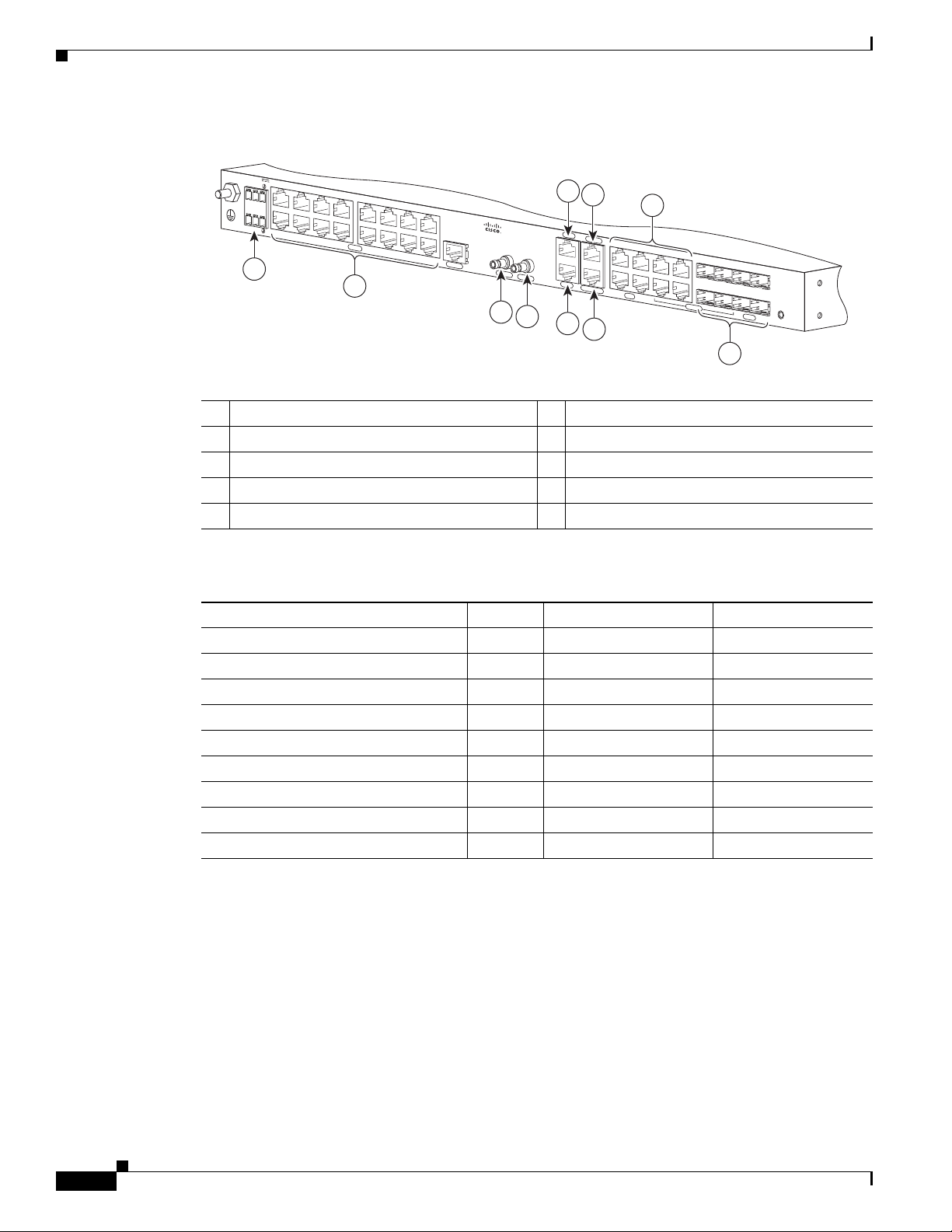
Figure 1-1 Cisco ASR 901 Router—Front View
1 ToD Port 7 BITS Port
2 Management Port 8 MINI-Coax Connector (1PPS)
3 Power LED 9 MINI-Coax Connector (10MHZ)
4 8 SFP Ports 10 Alarm
5 8 GE Ports 11 16 T1/E1 Ports
6 Console Port 12 Power Connector
Hardware Description
Cisco ASR 901 Router Ethernet Version Front View
Figure 1-2 shows the front view of the Cisco ASR 901 router with each interface module.
The front panel of the Cisco ASR 901 router, ethernet version has the following components:
• Eight RJ-45 jacks for copper Ethernet ports, labeled “100/1000” Ethernet.
• Eight SFP connectors for optical GE ports
• Two miniature coaxial connectors for 10MHZ and 1PPS timing
• A single RJ-45 connector for console, labeled “CONSOLE”
• A single RJ-45 jack for the BITS interface, labeled “BITS”
• A single RJ-45 jack for the ToD interface, labeled “ToD”
• A single alarm
• Two management ports
• The following LEDs
–
Ethernet ports
–
SFP ports
–
Chassis: Single LED for multiple conditions
OL-23778-01
Cisco ASR 901 Series Aggregation Services Router Hardware Installation Guide
1-3
Page 14
Hardware Description
SYSTEM
CONSOLE
BITS
1 PPS
MGMNT
TOD
10 MHz
ALARM
B
A
+
-
+
-
24V - 60V
3A
COMBO
SFP
NG-MRW-E
GE
USB
3
2
1
6
7
8
5
4
10
9
300097
11
Figure 1-2 Cisco ASR 901 Router Ethernet Version Front View
1 ToD Port 7 BITS Port
2 Management Port 8 MINI-Coax Connector (1PPS)
3 Power LED 9 MINI-Coax Connector (10MHZ)
4 8 SFP Ports 10 Alarm
5 8 GE Ports 11 Power Connector
6 Console Port
Chapter 1 Introduction
Cisco ASR 901 Router Rear View
Figure 1-3 shows the rear view of the Cisco ASR 901 router including the orientation of the following
components:
• Two blowing fans
• Mounting point for the 2-hole lug. For more information, see the Connecting the Chassis Ground
and Power, page 3-5
Figure 1-3 Cisco ASR 901 Router—Rear View
Cisco ASR 901 Series Aggregation Services Router Hardware Installation Guide
1-4
1 Fan
2 Grounding Point Lug
282342
2
1
OL-23778-01
Page 15

Chapter 1 Introduction
LEDs
The Cisco ASR 901 chassis and interface modules contain LEDs to assist in troubleshooting. For more
detailed description of the LEDs, see the “
Power Supply
The Cisco ASR 901 router is equipped with an internal -27/-72 volts Direct Current (VDC).
Safety Precautions
Observe the following general safety precautions and recommendations in planning the source power
requirements for the Cisco
Guidelines” section on page 2-1:
• Check the power at your site before router installation (and periodically after installation) to ensure
clean power (free of spikes and noise) is being received.
• Always disconnect the power source and unplug the power cable before working on the router.
Power Supply
Reading the LEDs, page A-4.
ASR 901 router (for additional safety information, see the “Safety
Warning
Warning
Warning
• Install proper grounding for the site to avoid damage from lightning and power surges.
To avoid electric shock, do not connect safety extra-low voltage (SELV) circuits to telephone-network
voltage (TNV) circuits. LAN ports contain SELV circuits, and WAN ports contain TNV circuits. Some
LAN and WAN ports both use RJ-45 connectors. Use caution when connecting cables.
There is the danger of explosion if the battery is replaced incorrectly. Replace the battery only with
the same or equivalent type recommended by the manufacturer. Dispose of used batteries according
to the manufacturer’s instructions.
This unit might have more than one power supply connection. All connections must be removed to
de-energize the unit.
Table 1-1 lists the DC power supply specifications for the Cisco ASR 901 router.
Table 1-1 Cisco ASR 901 Router Power Supply Specifications
Specification Value
DC power supply input voltage -24/-72 VDC
Maximum input current 3 A
Wire gauge for DC input power
connections
Power dissipation 60 Watts
Statement 1028
Statement 1015
16 AWG
Statement 1021
OL-23778-01
Cisco ASR 901 Series Aggregation Services Router Hardware Installation Guide
1-5
Page 16
Power Supply
Chapter 1 Introduction
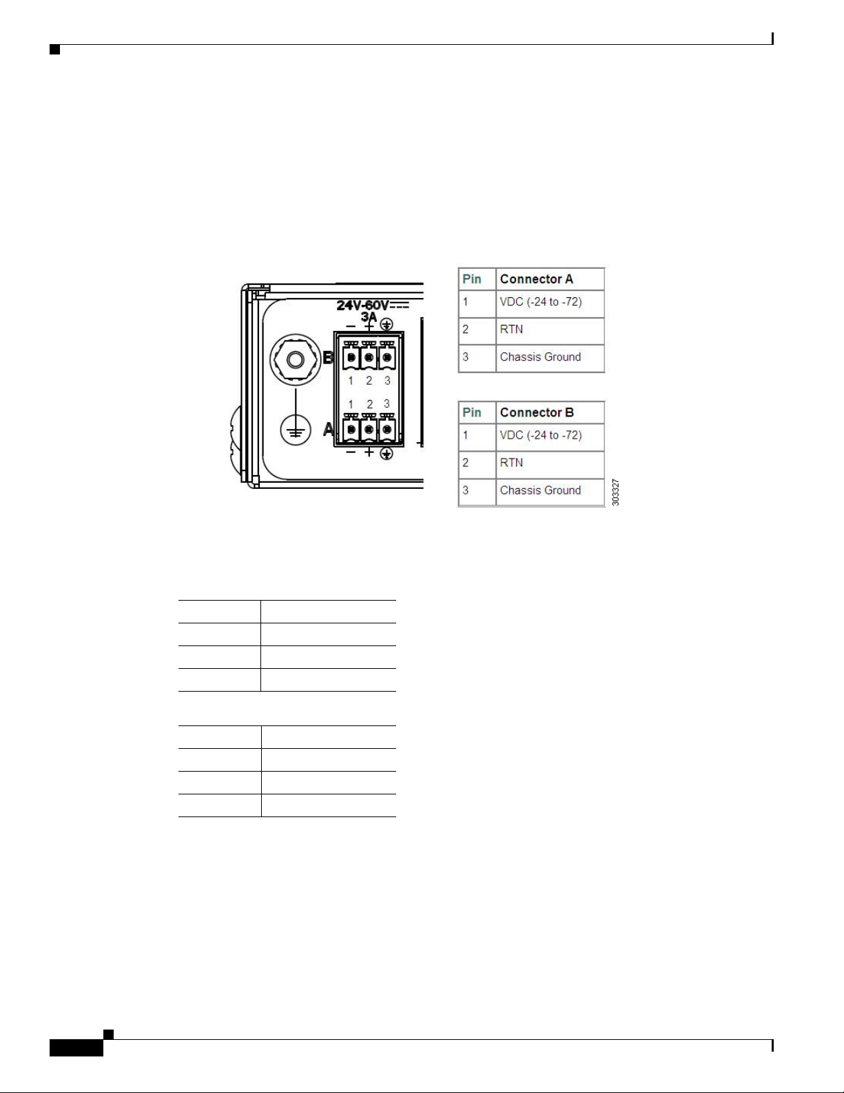
The Cisco ASR 901 router uses two 3 pin connectors (part number 27-2030-01) for input to the power
supply. The terminal block is part of the accessory kit (part number 53-3085-01/53-3295-0), which ships
with the Cisco
The ground wire connects to a 2-hole plug, which connects to the corresponding mounting point.
With the connector installed in the chassis, the pins are numbered as 1,2, and 3, respectively.
Figure 1-4 Cisco ASR 901 Router—Power Supply Connector Pinouts
ASR 901 router.
Table 1-2 lists the pinout configurations for the connector, based on the power source.
Table 1-2 Power Supply Connector Pinouts (-24/-72 VDC Application)
Pin Connector A
1 VDC (-24 to -72)
2 RTN
3 Chassis Ground
Pin Connector B
1 VDC (-24 to -72)
2 RTN
3 Chassis Ground
You can use connector A or B or both.
1-6
Cisco ASR 901 Series Aggregation Services Router Hardware Installation Guide
OL-23778-01
Page 17
Chapter 1 Introduction
Environmental Monitoring Temperature Sensor
Environmental Monitoring Temperature Sensor
The Cisco ASR 901 router has a temperature sensor to detect overtemperature conditions inside the
chassis. The overtemperature detection trips at 70°C. This condition is reported to the processor as an
interrupt, where the software generates the appropriate alarms. If the router reaches a temperature of
85°C, the power supply cycles itself to prevent the router from exceeding the maximum temperature
while being powered up.
System Specifications
Table 1-3 lists the system specifications for the Cisco ASR 901 router.
Table 1-3 Cisco ASR 901 Router System Specifications
Description Specification
Dimensions (H x W x D) 1.7 x 17.4 x 8.25 in. (4.37 cm x 44.2 cm x 21.0 cm) 1 RU (rack unit)
in a 19-inch (48.3
Weight 3.1 Kgs (7 pounds)
Console and Auxiliary ports RJ-45 connector
Operating Temperature Operating temperature range is -40°C to +65°C (-40 to+149°F)
Non-Operational Temperature Temperature: -40 to 70 degrees C (-40 to 21.1 F)
Operating Humidity 10 to 90% RH (non-condensing)
Non-Operational Humidity Upto 93% RH
Operating Altitude 13,800 ft. (4206 m)
Operating Vibration 0.15 G, 10 to 500 Hz/100 minutes per axis
Non-Operational Vibration 0.8 G, 10 to 500 Hz/30 minutes per axis
Operating Acoustics 60 db
Air Flow Side to side
cm) rack
Router Interface Numbering
Each network interface on a Cisco ASR 901 router is identified by a slot number and a port number,
explained in this sequence:
• Logical slot numbers starts from 0 for all built-in interfaces. The numbering format is Interface
type Slot number/Interface number.
type.
• Logical interface numbering for T1/E1 ports on the TDM interface module runs from 0/0 through
0/15. Ports are numbered bottom to top, left to right.
• Logical interface numbering for the built-in ethernet ports runs from g0/0 through g0/3, the combo
ports run from g0/4 to g0/7 and the SFP ports run from g0/8 through g0/11. The GE ports are
numbered bottom to top, left to right.
Cisco ASR 901 Series Aggregation Services Router Hardware Installation Guide
OL-23778-01
Interface (port) numbers begin at logical 0 for each interface
1-7
Page 18
Regulatory Compliance
Chapter 1 Introduction
Figure 1-5 Cisco ASR 901 Router Port Numbers
24V - 60V
3A
-
+
B
A
-
+
T1/E1
10
ALARM
1 PPS
9
8
1 ToD Port 6 BITS Port
2 Management Port 7 MINI-Coax Connector (1PPS)
3 8 SFP Ports 8 MINI-Coax Connector (10MHZ)
4 8 GE Ports 9 16 T1/E1 Ports
5 Console Port 10 Power Connector
10 MHz
1
2
TOD
MGMNT
BITS
CONSOLE
7
6
5
3
GE
COMBO
SFP
4
NG-MRW
SYSTEM
282343
Table 1-4 Cisco ASR 901 Router Interface Labels
Interface Number Location Label
RJ45 jacks for copper ethernet ports 8 Onboard 100/1000 ETHERNET
SFP connector for optical GE ports 8 Onboard Fiber ETHERNET
RJ45 connector for console 1 Onboard CON/AUX
RJ45 jack for BITS interface 1 Onboard BITS
RJ45 jack for Time-of-Day interface 1 Onboard TOD
1PPS mini-coax timing connector 1 Onboard 1PPS
10Mhz mini-coax timing connector 1 Onboard 10MHZ
RJ48 jacks for T1/E1 ports 16 T1/E1 interface module T1/E1
Power connector 1 Onboard Power Connector
Regulatory Compliance
For regulatory compliance and safety information, see Cisco Regulatory Compliance and Safety
Information for Cisco ASR 901 Series Aggregation Services Router.
1-8
Cisco ASR 901 Series Aggregation Services Router Hardware Installation Guide
OL-23778-01
Page 19
Preparing to Install the Router
This chapter describes site requirements and equipment used to install the Cisco ASR 901 router. It
includes the following sections:
• Safety Guidelines, page 2-1
• Prerequisites, page 2-4
• Site Planning, page 2-4
• Console Port Considerations, page 2-8
Safety Guidelines
Before you begin installing the Cisco ASR 901 router, review the safety guidelines in Safety
Precautions, page 1-5, and the Rack-Mounting Configuration Guidelines, page 3-2 to avoid injuries or
damaging the equipment.
CHAP TER
2
In addition, before replacing, configuring, or maintaining the Cisco ASR 901 router, review the safety
warnings listed in the document
901 Series Aggregation Services Router.
Safety with Equipment
The following guidelines help ensure your safety and protect the equipment. This list does not include
all the potentially hazardous situations, so be alert.
Warning
Before connecting the system to the power source, read the installation instructions.
• Before moving the system, always disconnect all the power cords and interface cables.
• Never assume that power is disconnected from a circuit; always check.
• Before and after installation, keep the chassis area clean and dust-free.
• Keep tools and assembly components away from walk areas to avoid tripping over them.
• Do not work alone in potentially hazardous conditions.
• Do not perform any action that creates a potential hazard to people or makes the equipment unsafe.
• Do not wear loose clothing that may get caught in the chassis.
Cisco Regulatory Compliance and Safety Information for Cisco ASR
Statement 1004
OL-23778-01
Cisco ASR 901 Series Aggregation Services Router Hardware Installation Guide
2-1
Page 20
Safety Guidelines
• When working under conditions hazardous to your eyes, wear safety glasses.
Safety with Electricity
Chapter 2 Preparing to Install the Router
Warning
Warning
Warning
Warning
Warning
Before performing any of the following procedures, ensure that power is removed from the DC circuit.
Statement 1003
This unit is intended for installation in restricted access areas. A restricted access area can be
accessed only through the use of a special tool, lock and key, or other means of security.
Statement 1017
To avoid electric shock, do not connect safety extra-low voltage (SELV) circuits to telephone-network
voltage (TNV) circuits. LAN ports contain SELV circuits, and WAN ports contain TNV circuits. Some
LAN and WAN ports both use RJ-45 connectors.
Before working on equipment that is connected to power lines, remove jewelry (including rings,
necklaces, and watches). Metal objects will heat up when connected to power and ground and can
cause serious burns or weld the metal object to the terminals.
Before working on a chassis or working near power supplies, unplug the power cord on AC units;
disconnect the power at the circuit breaker on DC units.
Statement 1021
Statement 43
Statement 12
2-2
Warning
Warning
Warning
During periods of lightning activity, do not work on the system or connect or disconnect cables.
Statement 1001
There is the danger of explosion if the battery is replaced incorrectly. Replace the battery only with
the same or equivalent type recommended by the manufacturer. Dispose of used batteries according
to the manufacturer’s instructions.
This unit might have more than one power supply connection. All connections must be removed to
de-energize the unit.
Statement 1028
Statement 1015
When working on electrical equipment, follow these guidelines:
• Locate the room’s emergency power switch. If an electrical accident occurs, you can quickly switch
off the power.
• Before working on the system, switch off the DC main circuit breaker and disconnect the power
terminal block cable.
• Disconnect all power before performing the following:
Cisco ASR 901 Series Aggregation Services Router Hardware Installation Guide
OL-23778-01
Page 21

Chapter 2 Preparing to Install the Router
–
Working on or near power supplies.
–
Installing or removing a router chassis, or network processor module.
–
Performing most hardware upgrades.
• Never install equipment that appears damaged.
• Carefully examine your work area for possible hazards, such as wet floors, ungrounded power
extension cables, and missing safety grounds.
• Never assume that power is disconnected from a circuit; always check.
• Never perform any action that creates a potential hazard to people or makes the equipment unsafe.
• If an electrical accident occurs, proceed as follows:
–
Use caution, and do not become a victim yourself.
–
Switch off power to the router.
–
If possible, send another person to get medical aid. Otherwise, determine the condition of the
victim, and then call for help.
–
Determine whether the person needs rescue breathing or external cardiac compressions; then
take appropriate action.
In addition, use the following guidelines when working with any equipment that is disconnected from a
power source, but still connected to telephone wiring or network cabling:
• Never install telephone wiring during a lightning storm.
Safety Guidelines
• Never install telephone jacks in wet locations unless the jack is specifically designed for it.
• Never touch un-insulated telephone wires or terminals unless the telephone line is disconnected at
the network interface.
• When installing or modifying telephone lines, use caution.
Preventing Electrostatic Discharge Damage
Electrostatic Discharge (ESD) can damage equipment and impair electrical circuitry. ESD can occur
when electronic printed circuit cards are improperly handled, and can cause complete or intermittent
failures. When removing and replacing modules, always follow ESD prevention procedures:
• Ensure that the router chassis is electrically connected to earth ground.
• Wear an ESD-preventive wrist strap, ensuring that it makes good skin contact. To channel unwanted
ESD voltages safely to ground, connect the clip to an unpainted surface of the chassis frame. To
guard against ESD damage and shocks, the wrist strap and cord must operate effectively.
• If no wrist strap is available, ground yourself by touching a metal part of the chassis.
Caution For the safety of your equipment, periodically check the resistance value of the antistatic wrist strap. It
should be between 1 and 10 Mohm.
OL-23778-01
Cisco ASR 901 Series Aggregation Services Router Hardware Installation Guide
2-3
Page 22

Prerequisites
Prerequisites
Before installing the Cisco ASR 901 router, it is important to prepare for installation by:
• Preparing the site (site planning) and reviewing the installation plans or method of procedures
• Unpacking and inspecting the Cisco ASR 901 router.
• Gathering tools and test equipment required to properly install the Cisco ASR 901 router.
Site Planning
Ideally, you should have prepared the installation site beforehand. As part of your preparation, obtain a
floor plan of the site and the equipment rack where the Cisco
Determine the location of any existing routers and their interconnections, including communications and
power. Following the air flow guidelines (see the
adequate cooling air is provided to the router.
All personnel involved in the installation of the router including installers, engineers, and supervisors
should participate in the preparation of a Method of Procedure (MOP) for approval by the customer.
Chapter 2 Preparing to Install the Router
(MOPs).
ASR 901 router would be housed.
“Air Flow Guidelines” section on page 2-5), ensure that
Power Supply Considerations
Check the power at your site to ensure that you are receiving clean power (free of spikes and noise).
Install a power conditioner if necessary (see the
Warning
This equipment is designed for connection to TN and IT power systems.
Site Environment
Install the Cisco ASR 901 router in an equipment rack. The location of your router and the layout of your
equipment rack, or wiring room are extremely important considerations for proper operation. Cramped
equipment, inadequate ventilation, and inaccessible panels can cause malfunctions and shutdown, and
can make maintenance difficult. Plan to access the front and rear panels of the router.
Take the following precautions for an acceptable operating environment for your router and to avoid
environmentally caused equipment failures:
• Ensure that the room where your router operates has adequate air circulation. Electrical equipment
generates heat. Without adequate circulation, ambient air temperature may not cool the equipment
to acceptable operating temperatures.
• Always follow ESD-prevention procedures described in the “Preventing Electrostatic Discharge
Damage” section on page 2-3 to avoid damage to equipment. Damage from static discharge can
cause immediate or intermittent equipment failure.
Power Supply, page 1-5 for power requirements).
Statement 16
2-4
Cisco ASR 901 Series Aggregation Services Router Hardware Installation Guide
OL-23778-01
Page 23

Chapter 2 Preparing to Install the Router
Air Flow Guidelines
To ensure adequate air flow through the equipment rack, we recommend that you maintain a clearance
of at least 6 inches (15.24 cm) on each side of the rack at all times.
Caution If air flow through the equipment rack and the routers that occupy it is blocked or restricted, or if the
ambient air being drawn into the rack is too warm, an over temperature condition can occur within the
rack and the routers that occupy it.
The site should also be as dust-free as possible. Dust tends to clog the router fans, reducing the flow of
cooling air through the equipment rack and the routers. Thus, increasing the risk of an over temperature
condition.
Use the following guidelines to plan your equipment rack configuration:
• Mount the Cisco ASR 901 router in a 19-inch rack (with a 17.5- or 17.75-inch opening).
• Beside air flow, you must allow clearance around the rack for maintenance.
• Enclosed racks must have adequate ventilation. Ensure that the rack is not congested, because each
router generates heat. An enclosed rack should have louvered sides and a fan to provide cooling air.
Heat that is generated by equipment near the bottom of the rack can be drawn upward into the intake
ports of the equipment above.
Site Planning
• When mounting a chassis in an open rack, ensure that the rack frame does not block the intakes or
(on the left side of the chassis) or the exhaust (on the right side of the chassis).
• When a rack-installed equipment fails, especially equipment in an enclosed rack, try making the
equipment operate by itself, if possible. Power off other equipment in the rack (and in adjacent
racks) to give the router a maximum of cooling air and clean power.
Method of Procedure
Part of site preparation includes reviewing installation plans or method of procedures (MOPs). An
example of a MOP that includes pre-installation checklist of tasks, considerations to address and agree
upon before proceeding with the installation, is as follows:
1. Read this hardware installation guide.
2. Assign personnel.
3. Determine protection requirements for personnel, equipment, and tools.
4. Evaluate potential hazards that may affect service.
5. Schedule time for installation.
6. Determine space requirements.
7. Determine power requirements.
8. Identify required procedures or tests.
9. On an equipment plan, make a preliminary decision that locates each Cisco ASR 901 router that you
plan to install.
OL-23778-01
10. Verify the list of replaceable parts for installation (screws, bolts, washers, and so on) so that the parts
are identified.
Cisco ASR 901 Series Aggregation Services Router Hardware Installation Guide
2-5
Page 24

Site Planning
11. Check the required tools list to make sure the necessary tools and test equipment are available (see
the “Required Tools and Equipment” section on page 2-6).
12. Perform the installation.
Unpacking and Checking the Contents of your Shipment
The shipping package for the Cisco ASR 901 router is designed to reduce the possibility of product
damage associated with routine handling experienced during shipment. Do not remove the router from
its shipping container until you are ready to install it.
Note Do not discard the packaging materials used in shipping your Cisco ASR 901 router. You will need the
packaging materials in the future if you move or ship the router.
The Cisco ASR 901 router, cables, and any optional equipment you ordered may be shipped in more than
one container. When you unpack the containers, check the packing list to ensure that you receive all of
the following items:
• Router
Chapter 2 Preparing to Install the Router
• Accessory kit (part number 53-3085-01/53-3295-0 for the Cisco ASR 901), containing
–
Terminal block (part number 53-3085-01)
–
Two hole lug, 6-AWG ground wire, #10 blue stud (part number 32-0629-01)
–
Two pan-head Phillips screws used to attach the lug to the router, M5.0x10mm
–
Two cable guides (part number 700-01663-01)
–
Two pan-head Phillips screws used to attach the cable guides, M4,0x20mm (part number
48-0654-01)
Note There is no AC power option.
• Cisco Information Packet publication
Inspect all items for shipping damage. If an item appears to be damaged, or if you encounter problems
installing or configuring your router, contact customer service. The Cisco Information Packet provides
warranty, service, and support information.
Required Tools and Equipment
You need the following tools and equipment to install and upgrade the router and its components:
2-6
Warning
Cisco ASR 901 Series Aggregation Services Router Hardware Installation Guide
Only trained and qualified personnel should be allowed to install or replace this equipment.
Statement 49
• ESD-preventive cord and wrist strap.
• Number 2 Phillips screwdriver.
• Flat-blade screwdrivers: small, 3/16-inch (0.476 cm) and medium, 1/4-inch (0.625 cm).
OL-23778-01
Page 25

Chapter 2 Preparing to Install the Router
–
To install or remove modules
–
To remove the cover, if you are upgrading memory or other components
• Number 12-24 pan-head screws to secure the router to the equipment rack.
• Cables for connection to the WAN and LAN ports (depending on the configuration).
Note For more information on cable specifications, see Appendix B, “Cable Specifications”
• Ethernet hub or PC with a network interface card for connection to the Ethernet (LAN) ports.
• Console terminal (an ASCII terminal or a PC running terminal emulation software) is configured for
9600 baud, 8 data bits, no parity, and 2 stop bits.
• Console cable for connection to the console port.
• Ratcheting torque screwdriver with a Phillips head that exerts up to 15 pound-force inches (lbf-in)
of pressure.
• Crimping tool as specified by the ground lug manufacturer.
• 16-AWG copper wire for the power cord.
Site Planning
• Wire-stripping tools for stripping both 6-AWG and 18-AWG wire.
• Serial interfaces may require a channel service unit/data service unit (CSU/DSU).
Installation Checklist
To assist you with your installation and to provide a historical record of completed tasks and users, use
the following Installation Checklist. Make a copy of this checklist and mark the entries as you complete
each task. When the checklist is completed, include a copy of the checklist for each router in your Site
Log along with other records for your new router. See
Site Log, including a sample Site Log.
Installation Checklist for Site:
Router Name:
Task Verified by Date
Installation Checklist copied
Background information placed in Site Log
Site power voltages verified
Installation site power check completed
Required tools available
Additional equipment available
Router received
Documentation DVD received (if ordered)
Cisco Information Packet publication received
Chassis components verified
Initial electrical connections established
Appendix C, “Site Log” for information on the
OL-23778-01
Cisco ASR 901 Series Aggregation Services Router Hardware Installation Guide
2-7
Page 26

Console Port Considerations
Task Verified by Date
ASCII terminal (for local configuration) or
modem
Signal distance limits verified
Startup sequence steps completed
Initial operation verified
Software image verified
Creating a Site Log
The site log provides a record of all actions related to installing and maintaining the router. Keep it in
an accessible place near the chassis so that anyone who performs tasks has access to it.
Create the site log prior to installation. (See Appendix C, “Site Log” for more detailed information on
the site log as well as a sample site log that can be used to make copies.)
Chapter 2 Preparing to Install the Router
(for remote configuration)
Console Port Considerations
The Cisco ASR 901 router provides a single console port (labeled CONSOLE). A single RJ-45 cable is
used for a console connection.
This section describes important cabling information to consider before connecting a console
terminal—either an ASCII terminal or a PC running terminal emulation software—or a modem to the
console port. The console port provides access to the router either locally (using a console terminal), or
remotely (using a modem).
Note The Cisco ASR 901 router uses only console port.
Note Console and rollover cables are not included with the Cisco ASR 901 router. You can order the console
cable from Cisco Systems, Inc. (Part number ACS-1900ASYN=).
Console Port Connections
The router provides an EIA/TIA-232 asynchronous serial console port (RJ-45). Depending on the cable
and the adapter used, this port appears as a data terminal equipment (DTE) or data communications
equipment (DCE) device at the end of the cable.
To connect an ASCII terminal to the console port, use the RJ-45 rollover cable with the female
RJ-45-to-DB-25 adapter (labeled TERMINAL). To connect a PC running terminal emulation software
to the console port, use the RJ-45 rollover cable with the female RJ-45-to-DB-9 adapter (labeled
TERMINAL). The default parameters for the port are 9600 baud, 8
As a console port, hardware flow control is not supported. For instructions on installing a console
terminal, see the
“Connecting the Console Port” section on page 3-11.
data bits, no parity, and 2 stop bits.
2-8
Cisco ASR 901 Series Aggregation Services Router Hardware Installation Guide
OL-23778-01
Page 27

Chapter 2 Preparing to Install the Router
For cable and port pinouts, see the online document Cisco Modular Access Router Cable Specifications.
This document is provided on the documentation DVD that accompanied your router (if ordered), and is
also available online at Cisco.com.
Console Port Considerations
OL-23778-01
Cisco ASR 901 Series Aggregation Services Router Hardware Installation Guide
2-9
Page 28

Console Port Considerations
Chapter 2 Preparing to Install the Router
2-10
Cisco ASR 901 Series Aggregation Services Router Hardware Installation Guide
OL-23778-01
Page 29

Warning
CHAP TER
3
Installing the Cisco ASR 901 Mobile Wireless Router
This chapter describes how to install the Cisco ASR 901 router, and how to connect it to networks and
external devices. These are the following sections:
• Network Modules, page 3-1
• Mounting the Cisco ASR 901 Router, page 3-2
• Connecting the Chassis Ground and Power, page 3-5
• Installing and Removing SFP Modules, page 3-9
• Connecting Cables, page 3-11
• Powering On the Router, page 3-15
Only trained and qualified personnel should be allowed to install, replace, or service this equipment.
Statement 1030
Warning
This unit is intended for installation in restricted access areas. A restricted access area can be
accessed only through the use of a special tool, lock and key, or other means of security.
Statement 1017
Network Modules
You can order the Cisco ASR 901 router with the following interface modules.
• T1/E1 interface module
• SFP Ethernet interface module
• RJ-45 Ethernet interface module
Interface modules are installed and shipped with the router; they are not field replaceable.
OL-23778-01
Cisco ASR 901 Series Aggregation Services Router Hardware Installation Guide
3-1
Page 30
Mounting the Cisco ASR 901 Router
Mounting the Cisco ASR 901 Router
Each Cisco ASR 901 router includes rack-mounting brackets. Using the rack-mounting brackets, you
can front-mount theCisco ASR 901 router in a 19-inch (48.3-cm) equipment rack that conforms to the
EIA-310-D specification (the inside width of the rack should be 17.72 to 17.80 inches [45 to 45.21 cm]).
Using the two rack-mounting brackets for mounting (part number 700-33522-01), you can recess
Cisco
ASR 901 router in the equipment rack. This arrangement provides extra space in front of the router
for the cables and allows you to close the doors of racks equipped with front-close doors.
If you need to attach or replace the rack-mounting brackets, see the “Attaching the Rack-Mounting
Brackets” section on page 3-3.
The rack-mounting brackets are slotted to allow the router to be mounted in racks with EIA 1.25-inch
(3.175-cm) or WECO 1.0-inch (2.54-cm) hole spacing. When installed in the rack, the Cisco
router requires one EIA 1.75-inch (4.4-cm) vertical mounting space (or 1 rack unit [RU]) for mounting
(see the
Caution Allow clearance on either side of the Cisco ASR 901 router for cooling air to be drawn in through the
left side and circulated through the chassis and out the two fan exhaust ports mounted on the other side
of the chassis.
“Mounting the Cisco ASR 901 Router in a Rack” section on page 3-3).
Chapter 3 Installing the Cisco ASR 901 Mobile Wireless Router
ASR 901
Rack-Mounting Configuration Guidelines
Follow these guidelines to configure the equipment rack:
• When mounting the router to an equipment rack, ensure that the rack is bolted to the floor.
• Because you may install more than one router into the rack, ensure that the weight of all of the
routers installed does not make the rack unstable.
Caution Some equipment racks are also secured to ceiling brackets, if necessary, due to the weight of the
equipment in the rack. Make sure that the rack you are using to install the routers is secured to the
building structure.
• As mentioned in the “Air Flow Guidelines” section on page 2-5, maintain a 6-inch (15.24-cm)
clearance on each side of the router to ensure adequate air intake and exhaust.
• Avoid installing the routers in an overly congested rack. Air flowing to or from other routers in the
rack might interfere with the normal flow of cooling air through the routers, increasing the potential
for overtemperature conditions within the routers.
• Allow at least 19 inches (48.7 cm) of clearance at the front and rear of the rack for router
maintenance.
• Follow your local practices for cable management. Ensure that cables to and from the routers do not
impede access to perform equipment maintenance or upgrades.
3-2
Cisco ASR 901 Series Aggregation Services Router Hardware Installation Guide
OL-23778-01
Page 31
Chapter 3 Installing the Cisco ASR 901 Mobile Wireless Router
282344
1
Attaching the Rack-Mounting Brackets
Complete the following tasks to install, replace, or rearrange the rack-mounting brackets so you can then
mount the Cisco
rack-mounting brackets to front-mount the Cisco
Step 1 Locate the mounting holes of the Cisco ASR 901 router.
Step 2 Align the rack-mounting bracket with the Cisco ASR 901 router and position with the four #6-32 x
0.25-inch screws (provided) (see Figure 3-1 for front-mounting).
Figure 3-1 Attaching the Bracket for Front-Mounting
ASR 901 router in a 19-inch (48.3-cm) equipment rack. You can use the same
Mounting the Cisco ASR 901 Router
ASR 901 router in the equipment rack.
1 Rack mount bracket
Step 3 Insert the screws (four places) and tighten using a Number 2 Phillips screwdriver.
Step 4 Repeat Steps 2 and 3 for the other rack-mounting bracket.
Proceed to the next section, “Mounting the Cisco ASR 901 Router in a Rack” to continue the
installation.
Mounting the Cisco ASR 901 Router in a Rack
Typically, the Cisco ASR 901 router mounts to a 19-inch (48.3-cm) 2-post equipment rack with
rack-mounting brackets that attach toward the front of the router sides. The inside width between the two
posts or mounting strips (left and right) must be at least 17.72 to 17.80 inches [45 to 45.21 cm]. For more
information about the equipment rack, see
No vertical clearance is necessary above or below the router when it is mounted in the rack.
“Hardware Description” section on page 1-1.
OL-23778-01
Cisco ASR 901 Series Aggregation Services Router Hardware Installation Guide
3-3
Page 32

Mounting the Cisco ASR 901 Router
To secure the Cisco ASR 901 router to the equipment rack, you must use the two mounting screws
(provided) for each side or follow your local practices for installing the router into your equipment rack.
Ensure that the rack-mount brackets are securely fastened. For more information, see the
Rack-Mounting Brackets” section on page 3-3.
To mount the Cisco ASR 901 router into the equipment rack, perform the following procedure.
Caution To prevent injury, review the “Safety Guidelines” section on page 2-1 and the “Rack-Mounting
Configuration Guidelines” section on page 3-2 before installing the Cisco ASR 901 router in the
equipment rack.
Step 1 Locate the equipment rack position where you plan to install the router.
Step 2 Verify that there are no obstructions and ensure that the equipment rack is stabilized.
Step 3 Position the router in the equipment rack lining up the bracket holes on the router with the holes on the
rack and secure with four #6-32 x 0.25-inch mounting screws (two on each side).
Note The vertical spacing for EIA equipment racks is 1.75 inches (4.44 cm), with mounting holes
Chapter 3 Installing the Cisco ASR 901 Mobile Wireless Router
“Attaching the
spaced 1.5 inches (3.81 cm) apart.
Step 4 Tighten the screws using a 1/4-inch flat-blade screwdriver (each side).
Attaching the Cable Guides
Complete the following steps to attach the two cable guides to the front of the mounting brackets. This
procedure is optional.
Note The cable guides are useful only if your router is front-mounted. Do not attach the cable guides if your
router is center-mounted or recess-mounted.
Use the cable guides to dress the cables that attach to the front of the Cisco ASR 901 router. The cable
guides allow you to gather the cables and direct them to the left and right sides of the router. This helps
to keep the cables from obscuring the fronts of lower routers in the same rack.
Step 1 In the accessory kit, locate the two cable guides (part number 700-01663-01) and two M4.0x20mm
Phillips screws used to attach the cable guides (part number 48-0654-01).
Step 2 Position the cable guide over the threaded hole in the front flange of either the left or right mounting
bracket. The threaded hole is located midway between the two slotted holes used to mount the unit to
the rack.
3-4
Cisco ASR 901 Series Aggregation Services Router Hardware Installation Guide
OL-23778-01
Page 33

Chapter 3 Installing the Cisco ASR 901 Mobile Wireless Router
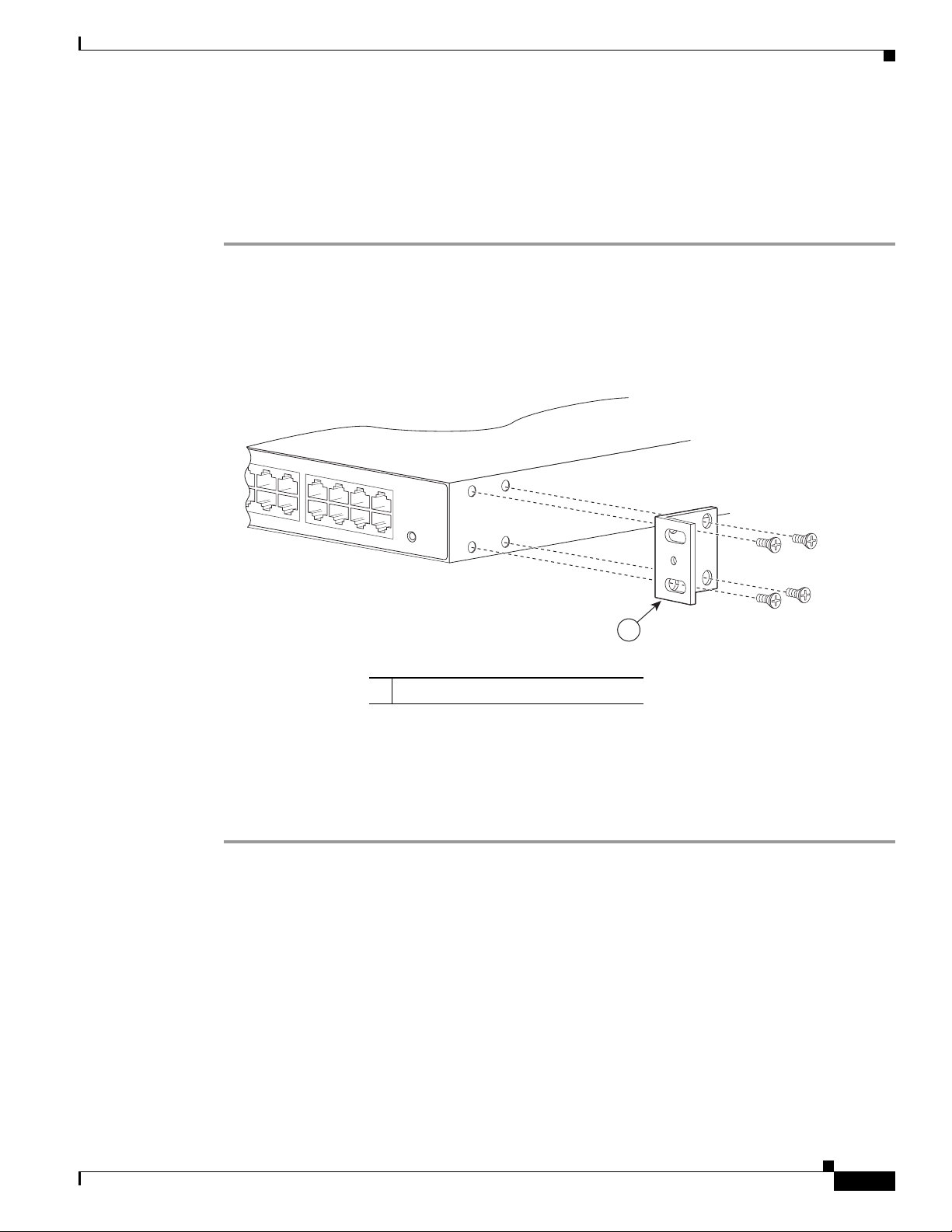
Figure 3-2 Attaching the Cable Guide
Step 3 Use an M4.0x20mm Phillips screw to fix the cable guide to the mounting bracket. Do not over-tighten
the screw.
Step 4 Repeat Steps 2 and 3 to attach the other cable guide.
Note If you find it awkward to insert the screw while holding the cable guide in place, you can first insert the
screw only far enough so that it does not fall out. Then, using the slot in the mounting pillar of the cable
guide, slide the cable guide into place around the screw. Finally, tighten the screw to fix the cable guide
to the mounting bracket.
Mounting the Cisco ASR 901 Router
282345
Connecting the Chassis Ground and Power
Before you connect power or turn on power to the Cisco ASR 901 router, you must provide an adequate
chassis ground (earth) connection to your router.
Grounding the Cisco ASR 901 Router
The Cisco ASR 901 router provides a grounding point on the rear of the unit for a 2-hole lug.
To ensure the chassis ground connection that you provide is adequate, you need the following parts and
tools:
• Ratcheting torque screwdriver with Phillips head that exerts up to 15 pound-force inches (lbf-in) of
pressure for attaching the ground wire to the router.
• Crimping tool as specified by the ground lug manufacturer
• 16-AWG copper wire for the power cord
• Wire-stripping tools appropriate to the wire you are using
Caution Before making connections to the Cisco ASR 901 router, ensure that you disconnect the power at the
circuit breaker. Otherwise it may result in severe injury or damage to the router.
OL-23778-01
Cisco ASR 901 Series Aggregation Services Router Hardware Installation Guide
3-5
Page 34

Mounting the Cisco ASR 901 Router
282342
2
1
Chapter 3 Installing the Cisco ASR 901 Mobile Wireless Router
Warning
Warning
Warning
This equipment must be grounded. Never defeat the ground conductor or operate the equipment in the
absence of a suitably installed ground conductor. Contact the appropriate electrical inspection
authority or an electrician if you are uncertain that suitable grounding is available.
Use copper conductors only.
Statement 1025
Statement 1024
When installing the unit, the ground connection must always be made first and disconnected last.
Statement 42
Figure 3-3 shows the grounding point marked on the rear panel of the Cisco ASR 901 router for ease of
installation
Figure 3-3 Grounding Point
1 Fan
2 Grounding Point Lug
This unit is to be installed in a restrictive access location and must be permanently grounded to minimum
6-AWG copper ground wire.
Complete the following steps to ground the Cisco ASR 901 router using a 2-hole lug and the
corresponding mounting point. Most carriers require a 6-AWG ground connection. Verify your carrier’s
requirements for the ground connection.
Step 1 In the accessory kit, locate the 2-hole lug, 2 pan-head Phillips head screws used to attach the lug to the
router, and 6-AWG ground wire. (Lug, screws, and wire are part number 32-0629-01.)
Step 2 Set the parts aside.
Step 3 If your ground wire is insulated, use a wire-stripping tool to strip the ground wire to 0.5 inch ± 0.02 inch
(12.7 mm ±0.5 mm) for the ring terminal (Figure 3-4).
.
Cisco ASR 901 Series Aggregation Services Router Hardware Installation Guide
3-6
OL-23778-01
Page 35

Chapter 3 Installing the Cisco ASR 901 Mobile Wireless Router
Insulation
Wire lead
0.5 in. (12.7 mm) ± 0.02 in. (0.5 mm)
60528
60529
Figure 3-4 Stripping a Ground Wire
Step 4 Slide the open end of your ground lug over the exposed area of the ground wire.
Step 5 Using a crimping tool (as specified by the ground lug manufacturer), crimp the ground lug to the ground wire
(Figure 3-5).
Figure 3-5 Crimping a Ground Lug onto the Ground Wire
Mounting the Cisco ASR 901 Router
Step 6 Use a Phillips head screwdriver to attach the ground lug and wire assembly to the front of the router with
the 2 screws from the accessory kit.
Step 7 Connect the other end of the ground wire to a suitable grounding point at your site.
Power Connection Compliance
Warning
Warning
Note The installation must comply with the 2002 National Electric Code (NEC) and other applicable codes.
Before performing any of the following procedures, ensure that power is removed from the DC circuit.
Statement 1003
Use copper conductors only.
Statement 1025
OL-23778-01
Cisco ASR 901 Series Aggregation Services Router Hardware Installation Guide
3-7
Page 36

Mounting the Cisco ASR 901 Router
Wiring the DC-Input Power Source
Chapter 3 Installing the Cisco ASR 901 Mobile Wireless Router
Warning
This product relies on the building’s installation for short-circuit (overcurrent) protection. Ensure that
the protective device is rated not greater than 10 A minimum, 60 VDC.
Statement 1005
Complete the following steps to connect the DC power supply to the Cisco ASR 901 router:
Step 1 Switch off the DC power source at the circuit breaker, and place the circuit breaker in the Off position.
Step 2 Locate the 6-pin terminal block (part number 27-2030-01) (Figure 3-6). The terminal block is located in
the accessory kit (part number 53-3085-01 for the Cisco ASR 901 router), which is shipped with the
router.
Figure 3-6 6-Pin Te r m i na l B l o c k
282346
Step 3 Plug the 6-pin terminal block into the power connector located on the front side of the router.
Step 4 Connect one end of the customer-supplied power cord (16-AWG copper wire) to the site DC power
source.
Step 5 Plug the connector on the power supply cord into the 6-pin terminal block that you plugged into the rear
of the router in Step 3.
Warning
An exposed wire lead from a DC-input power source can conduct harmful levels of electricity. Be sure
that no exposed portion of the DC-input power source wire extends from the terminal block plug.
Statement 122
Warning
When installing this unit, secure all power cabling to avoid disturbing field-wiring connections.
Statement 38
Caution DO NOT power on the unit yet.
3-8
Cisco ASR 901 Series Aggregation Services Router Hardware Installation Guide
OL-23778-01
Page 37

Chapter 3 Installing the Cisco ASR 901 Mobile Wireless Router
86575
Installing and Removing SFP Modules
This section describes how to install and remove SFP modules. The modules are inserted into the
SFP
module slots on the front of the Cisco ASR 901 router. These field-replaceable modules provide
interfaces.
See the Release Notes for Cisco ASR 901 Series Aggregation Services Router for the list of supported
SFP
modules. Each port must match the wavelength specifications on the other end of the cable. For
reliable communications, the cable must not exceed 328 feet (100 meters).
For detailed instructions on installing, removing, and cabling the SFP module, see the SFP module
documentation.
Installing SFP Modules
Figure 3-7 shows an SFP module that has a bale-clasp latch.
Caution We strongly recommend that you do not install or remove fiber-optic SFP modules with cables attached
because of the potential damage to the cables, the cable connector, or the optical interfaces in the SFP
module. Disconnect all cables before removing or installing an SFP module.Removing and installing an
SFP module can shorten its useful life. Do not remove and insert SFP modules more often than is
absolutely necessary.
Installing and Removing SFP Modules
Figure 3-7 SFP Module with a Bale-Clasp Latch
Complete the following steps to insert an SFP module into the module slot:
Step 1 Attach an ESD-preventive wrist strap to your wrist and to a bare metal surface on the chassis.
Some SFP modules identify the top side of the module with transmit (TX) and receive (RX) markings
or arrows that show the direction of the connection.
Step 2 If the SFP module that you are using has the markings, use them to identify the top side of the module.
Step 3 Align the SFP module in front of the slot opening.
Step 4 Insert the SFP module into the slot until you feel the connector on the module snap into place in the rear
of the slot (see Figure 3-8).
OL-23778-01
Cisco ASR 901 Series Aggregation Services Router Hardware Installation Guide
3-9
Page 38

Installing and Removing SFP Modules
282347
SYSTEM
CONSOLE
BITS
MGMNT
TOD
COMBO
SFP
NG-MRW
GE
Figure 3-8 Installing an SFP Module into an SFP Module Slot
Step 5 For fiber-optic SFP modules, remove the dust plugs from the optical ports, and store them for later use.
Caution Do not remove the dust plugs from the fiber-optic SFP module port or the rubber caps from the
fiber-optic cable until you are ready to connect the cable. The plugs and caps protect the SFP module
ports and cables from contamination and ambient light.
Step 6 Insert the cable connector into the SFP module:
• For fiber-optic SFP modules, insert the line card or MT-RJ cable connector into the SFP module.
• For copper 1000BASE-T SFP modules, insert the RJ-45 cable connector into the SFP module.
Chapter 3 Installing the Cisco ASR 901 Mobile Wireless Router
Removing SFP Modules
Complete the following steps to remove an SFP module from a module receptacle:
Step 1 Attach an ESD-preventive wrist strap to your wrist and to a bare metal surface on the chassis.
Step 2 Disconnect the cable from the SFP module, and insert a dust plug into the cable end.
Tip For reattachment, note which cable connector plug is transmit (TX) and which is receive (RX).
Step 3 Unlock and remove the SFP module, as shown in Figure 3-9.
If the module has a bale-clasp latch, pull the bale out and down to eject the module. If the bale-clasp
latch is obstructed and you cannot use your index finger to open it, use a small, flat-blade screwdriver
or other long, narrow instrument to open the bale-clasp latch.
3-10
Cisco ASR 901 Series Aggregation Services Router Hardware Installation Guide
OL-23778-01
Page 39

Chapter 3 Installing the Cisco ASR 901 Mobile Wireless Router
282348
SYSTEM
CONSOLE
BITS
MGMNT
TOD
COMBO
SFP
NG-MRW
GE
1
Figure 3-9 Removing a Bale-Clasp Latch SFP Module by Using a Flat-Blade Screwdriver
1 Bale Clasp
Step 4 Grasp the SFP module between your thumb and index finger, and carefully remove it from the
module slot.
Step 5 For fiber-optic SFP modules, insert a dust plug into the optical ports of the SFP module to keep the
optical interfaces clean.
Step 6 Place the removed SFP module in an antistatic bag or other protective environment.
Connecting Cables
Connecting Cables
This section describes how to connect the Cisco ASR 901 router to external devices and networks. It
includes the following sections:
• Connecting the Console Port, page 3-11
• Connecting the Network Cables, page 3-13
• Dressing Router Cables, page 3-15
Connecting the Console Port
Warning
Note The console port functions are asynchronous serial ports; any devices connected to the console port must
Do not work on the system or connect or disconnect cables during periods of lightning activity.
Statement 1001
The Cisco ASR 901 router has a single console port that can function in DTE mode:
• DTE-mode console (terminal) port for connecting a console terminal
be cabled for asynchronous transmission. (Asynchronous is the most common type of serial device; for
example, most modems are asynchronous devices.)
OL-23778-01
The Cisco ASR 901 router uses RJ-45 ports for console port function.
Cisco ASR 901 Series Aggregation Services Router Hardware Installation Guide
3-11
Page 40

Connecting Cables
We provide the following cables and adapters for connecting the Cisco ASR 901 router to a console
terminal:
• One console adapter cable (RJ-45-to-DB-9, blue)
Types of RJ-45 Cables
Cisco products use the following three types of RJ-45 cables:
• Straight-through
• Crossover
• Rolled (or Rollover)
The Cisco ASR 901 router ships with and uses the rollover cable. For instructions on how to identify a
rollover cable, see
Console Port
Complete the following steps to connect a terminal or a PC running terminal emulation software to the
console port on the router:
Chapter 3 Installing the Cisco ASR 901 Mobile Wireless Router
Identifying a Rollover Cable, page B-5.
Step 1 Connect the terminal using an RJ-45 rollover cable and an RJ-45-to-DB-25 or RJ-45-to-DB-9 adapter
(labeled TERMINAL) to the console port. For cable pinouts, see the “Console Port Signals and Pinouts”
section on page B-3.
Note The RJ-45-to-DB-25 adapter (Cisco part number 29-0810-01) can be purchased from Cisco
Systems.
Step 2 Configure the terminal or terminal emulation software for 9600 baud, 8 data bits, no parity, and 2 stop
bits.
Note Hardware flow control is not possible on the console port.
3-12
Cisco ASR 901 Series Aggregation Services Router Hardware Installation Guide
OL-23778-01
Page 41

Chapter 3 Installing the Cisco ASR 901 Mobile Wireless Router
Connecting the Network Cables
This section describes how to connect the following router interfaces:
• Connecting Gigabit Ethernet Interface Cables, page 3-13
• Connecting T1 and E1 Interface Cables, page 3-13
• Connecting SFP Cables, page 3-14
• Connecting Cables to the BITS Interface, page 3-14
• Connecting GPS Cables, page 3-14
• Connecting GPS Cables, page 3-14
• Connecting to the Management Ethernet Port, page 3-15
Connecting Gigabit Ethernet Interface Cables
The RJ-45 port supports standard straight-through and crossover Category 5 unshielded twisted-pair
(UTP) cables. Cisco Systems does not supply Category 5 UTP cables; these cables are available
commercially.
Complete the following steps to connect the cable to the router Gigabit Ethernet port:
Connecting Cables
Step 1 Confirm that the router is powered off.
Step 2 Connect one end of the cable to the GE port on the router.
Step 3 Connect the other end to the BTS patch or demarcation panel at your site.
For more information about Gigabit Ethernet connectors including pinouts, see “Gigabit Ethernet
Connector Pinouts” section on page B-1
Connecting T1 and E1 Interface Cables
Complete the following steps to connect the cable to a router T1/E1 port:
Note You must close the relays on the card using the standalone subcommand. For more information, see the
Cisco ASR 901 Mobile Wireless Router Software Configuration Guide.
Step 1 Confirm that the router is powered off.
Step 2 Connect one end of the cable to the T1 or E1 (RJ-48C) port. Use a T1/E1 cable.
Step 3 Connect the other end to the BTS patch or demarcation panel at your site.
Step 4 Turn on power to the router (see “Powering On the Router” section on page 3-15 for more details).
OL-23778-01
For more information about T1/E1 connectors including pinouts, see “T1/E1 Port Pinouts” section on
page B-2.
Cisco ASR 901 Series Aggregation Services Router Hardware Installation Guide
3-13
Page 42

Connecting Cables
Connecting SFP Cables
Complete these steps to connect the cable to a router SFP port.
Step 1 Confirm that the router is powered off.
Step 2 Insert the SFP module patch cable into the slot until you feel the connector on the cable snap into place
in the rear of the slot.
Step 3 Connect the other end to the patch or demarcation panel at your site.
Step 4 Turn on power to the router (see “Powering On the Router” section on page 3-15 for more details).
For more information about SFP connectors, see “SFP Port Pinouts and Cable Specifications” section
on page B-2.
Connecting Cables to the BITS Interface
Complete these steps to connect the cable to the router BITS port:
Chapter 3 Installing the Cisco ASR 901 Mobile Wireless Router
Step 1 Confirm that the router is powered off.
Step 2 Connect one end of the cable to the BITS port using a T1/E1 cable.
Step 3 Connect the other end to the SETS unit.
Step 4 Turn on power to the router (see “Powering On the Router” section on page 3-15 for more details).
For more information about T1/E1 connectors including pinouts, see “BITS Port Pinouts” section on
page B-6.
Connecting GPS Cables
The following sections describe how to connect cables from the Cisco ASR 901 router to a GPS unit for
input or output timing or frequency.
• Connecting Cables to the 10Mhz or 1PPS Interface
• Connecting Cables to the ToD Interface
Connecting Cables to the 10Mhz or 1PPS Interface
Complete these steps to connect cables to the 10Mhz or 1PPS interface:
Step 1 Confirm that the router is powered off.
Step 2 Connect one end of a mini-coax cable to the GPS unit.
Step 3 Connect the other end of the mini-coax cable to the 10Mhz or 1PPS port on the Cisco ASR 901 router.
3-14
For instructions on how to configure clocking, see the Cisco ASR 901 Mobile Wireless Router Software
Configuration Guide.
Cisco ASR 901 Series Aggregation Services Router Hardware Installation Guide
OL-23778-01
Page 43

Chapter 3 Installing the Cisco ASR 901 Mobile Wireless Router
For more information about 10Mhz and 1PPS port pinouts, see “GPS Port Pinouts” section on page B-6.
Connecting Cables to the ToD Interface
Complete these steps to connect cables to the ToD interface for GPS timing.
Step 1 Confirm that the router is powered off.
Step 2 Connect one end of a straight-through Ethernet cable to the GPS unit.
Step 3 Connect the other end of the cable to the ToD port on the Cisco ASR 901 router.
For instructions on how to configure clocking, see the Cisco ASR 901 Router Software Configuration
Guide.
Note For more information about BITS port pinouts, see “Time of Day Pinouts” section on page B-6.
Powering On the Router
Connecting to Alarm Port
Use a straight cable to connect to the alarm port. For details on the pinouts, see “Alarm Port Pinouts”
section on page B-7.
Connecting to the Management Ethernet Port
Use a straight or a cross over ethernet cable to connect to the management ethernet port. For details on
the pinouts, see
“Management Ethernet Port Pinouts” section on page B-7.
Dressing Router Cables
Ensure all Cisco router cables are properly dressed so as not to interfere with each other or other pieces
of equipment. Use local practices to ensure that the cables attached to your router are properly dressed.
Note If your Cisco ASR 901 router is front-mounted, you can use the cable guide (found in the accessory kit)
to dress the cables.
To continue the installation, proceed to the next section, “Powering On the Router.”
Powering On the Router
Warning
OL-23778-01
Do not touch the power supply when the power cord is connected. For systems with a power switch,
line voltages are present within the power supply even when the power switch is off and the power
cord is connected. For systems without a power switch, line voltages are present within the power
supply when the power cord is connected.
Statement 4
Cisco ASR 901 Series Aggregation Services Router Hardware Installation Guide
3-15
Page 44

Powering On the Router
Chapter 3 Installing the Cisco ASR 901 Mobile Wireless Router
Warning
This equipment is intended to be grounded. Ensure that the host is connected to earth ground during
normal use.
Statement 39
Checklist for Power Up
Complete these steps to power on the Cisco ASR 901 router:
• Securely mount the router.
• Properly connect the power, network, and interface cables.
Interpreting Front-Panel LEDs
The Cisco ASR 901 router provides a number of LEDs on the front panel to monitor conditions and to
aid in troubleshooting problems. For a description of the LEDs, see the
page A-4.
Power-On Procedure
Complete these steps to power on the Cisco ASR 901 router and verify its initialization and self-test:
“Reading the LEDs” section on
Step 1 Remove the tape from the circuit breaker switch handle.
Step 2 Restore power by moving the handle of the circuit breaker to the ON position.
The LED (labeled POWER) on the front panel should go ON and the fans operate.
Depending on your installation, other front-panel LEDs can also come on.
Note If you encounter problems when you power on the router, see Appendix A, “Troubleshooting”.
Formatting Procedures for Flash Memory
We recommend that you erase (Class B) to initialize with a Class B Flash file system.
The Class B Flash file system is also known as the low end file system (LEFS).
Formatting Flash Memory as a DOS File System
To format the flash memory, or to remove the files from it, use the erase flash: command.
The following is sample output for formatting the flash memory, formatted with a Class B flash file
system:
R#erase flash:
Erasing the flash filesystem will remove all files! Continue? [confirm]
Erasing device
3-16
Cisco ASR 901 Series Aggregation Services Router Hardware Installation Guide
OL-23778-01
Page 45

Chapter 3 Installing the Cisco ASR 901 Mobile Wireless Router
eeeeeeeeeeeeeeeeeeeeeeeeeeeeeeeeeeeeeeeeeeeeeeeeeeeeeeeeeeeeeeeeeeeeeeeeeeeeeeeeeeeeeeeeee
eeeeeeeeeeeeeeeeeeeeeeeeeeeeeeeeeeeeeeeeeeeeeeeeeeeeeeeeeeeeeeeeeeeeeeeeeeeeeeeeeeeeeeeeee
eeeeeeeeeeeeeeeeeeeeeeeeeeeeeeeeeeeeeeeeeeeeeeeeeeeeeeeeeeeeeeeeeeeeeeeeeeeeeeeeeeeeeeeeee
eeeeeeeeeeeeeeeeeeeeeeeeeeeeeeeeeeeeeeeeeeeeeeeeeeeeeeeeeeeeeeeeeeeeeeeeeeeeeeeeeeeeeeeeee
eeeeeeeeeeeeeeeeeeeeeeeeeeeeeeeeeeeeeeeeeeeeeeeeeeeeeeeeeeeeeeeeeeeeeeeeeeeeeeeeeeeeeeeeee
eeeeeeeeeeeeeeeeeeeeeeeeeeeeeeeeeeeeeeeeeeeeeeeeeeeeeeeeeeeeeeeeeeeeeeeeeeeeeeeeeeeeeeeeee
eeeeeeeeeeeeeeeeeeeeeeeeeeeeeeeeeeeeeeeeeeeeeeeeeeeeeeeeeeeeeeeeeeeeeeeeeeeeeeeeeeeeeeeeee
...erased
Erase of flash: complete
File and Directory Procedures
The following sections describe file and directory procedures for flash memory, formatted with a Class
B flash file system.
Copying Files
To copy files to another location, enter the copy tftp:flash: command.
The following is sample output for copying the file from external location to the internal flash memory.
Router#copy tftp: flash:
Address or name of remote host []? 10.64.71.240
Source filename []? /ngmwr-advipservicesk9-mz
Destination filename [ngmwr-advipservicesk9-mz]?
Accessing tftp://10.64.71.240//ngmwr-advipservicesk9-mz...
Erase flash: before copying? [confirm]n
Loading /ngmwr-advipservicesk9-mz from 10.64.71.240 (via FastEthernet0/0):
!!!!!!!!!!!!!!!!!!!!!!!!!!!!!!!!!!!!!!!!!!!!!!!!!!!!!!!!!!!!!!!!!!!!!!!!!!!!!!!!!!!!!!!!!!
!!!!!!!!!!!!!!!!!!!!!!!!!!!!!!
[OK - 30480936 bytes]
Powering On the Router
Verifying checksum... OK (0xA6AD)
30480936 bytes copied in 196.968 secs (154751 bytes/sec)
Displaying Contents of the Flash Memory
To display the contents (directories and files) of the flash memory formatted with a Class B flash file
system, use the dir: command.
The following is sample output for displaying the contents of the flash memory with a Class B flash file
system:
Router#dir
Directory of flash:/
1 -rw- 30564420 <no date> ngmwr-advipservicesk9-mz
2 -rw- 30564420 <no date> ngmwr-backup
83623932 bytes total (22494964 bytes free)
Cisco ASR 901 Series Aggregation Services Router Hardware Installation Guide
OL-23778-01
3-17
Page 46

Powering On the Router
Deleting Files from the Flash Memory
To delete a file from the flash memory, use the delete: filename command followed by the squeeze flash:
command.
When a file is deleted in the Class B Flash file system, the memory space occupied by the deleted file is
not released until you use the squeeze command. Although the memory space once occupied by the
deleted file remains, the deleted file cannot be recovered. To release the memory space occupied by a
deleted file, enter the squeeze flash: command
The following is sample output for deleting a Cisco IOS file from the flash memory, and releasing the
memory space originally occupied by the file.
Router#dir
Directory of flash:/
1 -rw- 30564420 <no date> ngmwr-advipservicesk9-mz
2 -rw- 30564420 <no date> ngmwr-backup
83623932 bytes total (22494964 bytes free)
Router#delete ngmwr-advipservicesk9-mz
Delete filename [ngmwr-advipservicesk9-mz]?
Delete flash:ngmwr-advipservicesk9-mz? [confirm]
Chapter 3 Installing the Cisco ASR 901 Mobile Wireless Router
Router#show flash:
les_flash_info : 1006 :
System flash directory:
File Length Name/status
1 30564420 ngmwr-advipservicesk9-mz [deleted]
2 30564420 ngmwr-backup
[61128968 bytes used, 22494964 available, 83623932 total]
81920K bytes of processor board System flash (Read/Write)
Router#squeeze flash:
Squeeze operation may take a while. Continue? [confirm]
squeeze in progress...
eeeeeeeeeeeeeeeeeeeeeeeeeeeeeeeeeeeeeeeeeeeeeeeeeeeeeeeeeeeeeeeeeeeeeeeeeeeeeeeeeeeeeeeeee
eeeeeeeeeeeeeeeeeeeeeeeeeeeeeeeeeeeeeeeeeeeeeeeeeeeeeeeeeeeeeeeeeeeeeeeeeeeeeeeeeeeeeeeeee
eeeeeeeeeeeeeeeeeeeeeeeeeeeeeeeeeeeeeeeeeeeeeeeeeeeeeeeeeeeeeeeeeeeeeeeeeeeeeeeeeeeeeeeeee
eeeeeeeeeeeeeeeeeeeeeeeeeeeeeeeeeeeeeeeeeeeeeeeeeeeeeeeeeeeeeeeeeeeeeeeeeeeeeeeeeeeeeeeeee
eeeeeeeeeeeeeeeeeeeeeeeeeeeeeeeeeeeeeeeeeeeeeeeeeeeeeeeeeeeeeeeeeeeeeeeeeeeeeeeeeeeeeeeeee
eeeeeeeeeeeeeeeeeeeeeeeeeeeeeeeeeeeeeeeeeeeeeeeeeeeeeeeeeeeeeeeeeeeeeeeeeeeeeeeeeeeeeeeeee
eeeeeeeeeeeeeeeeeeeeeeeeeeeeeeeeeeeeeeeeeeeeeeeeeeeeeeeeeeeeeeeeeeeeeeeeeeeeeeeeeeeeeeeeee
eeeeeeeee
Squeeze of flash complete
Router#dir
Directory of flash:/
2 -rw- 30564420 <no date> ngmwr-backup
83623932 bytes total (22661932 bytes free)
Displaying File Content
To display the contents of a file in the flash memory, use the more flash: filename command.
The following is sample output from the more flash command on a flash card:
Cisco ASR 901 Series Aggregation Services Router Hardware Installation Guide
3-18
OL-23778-01
Page 47

Chapter 3 Installing the Cisco ASR 901 Mobile Wireless Router
Router# more flash:ngmwr-advipservicesk9-mz
00000000: 7F454C46 01020100 00000000 00000000 .ELF .... .... ....
00000010: 00020061 00000001 80008000 00000034 ...a .... .... ...4
00000020: 00000054 20000001 00340020 00010028 ...T ... .4. ...(
00000030: 00050008 00000001 0000011C 80008000 .... .... .... ....
00000040: 80008000 00628A44 00650EEC 00000007 .... .b.D .e.l ....
00000050: 0000011C 0000001B 00000001 00000006 .... .... .... ....
00000060: 80008000 0000011C 00004000 00000000 .... .... ..@. ....
00000070: 00000000 00000008 00000000 00000021 .... .... .... ...!
00000080: 00000001 00000002 8000C000 0000411C .... .... ..@. ..A.
00000090: 00000700 00000000 00000000 00000004 .... .... .... ....
000000A0: 00000000 00000029 00000001 00000003 .... ...) .... ....
000000B0: 8000C700 0000481C 00000380 00000000 ..G. ..H. .... ....
000000C0: 00000000 00000004 00000000 0000002F .... .... .... .../
000000D0: 00000001 10000003 8000CA80 00004B9C .... .... ..J. ..K.
000000E0: 00000020 00000000 00000000 00000008 ... .... .... ....
000000F0: 00000000 0000002F 00000001 10000003 .... .../ .... ....
00000100: 8000CAA0 00004BBC 00623FA4 00000000 ..J ..K< .b?$ ....
00000110: 00000000 00000008 00000000 3C1C8001 .... .... .... <...
00000120: 679C4A80 3C018001 AC3DC70C 3C018001 g.J. <... ,=G. <...
00000130: AC3FC710 3C018001 AC24C714 3C018001 ,?G. <... ,$G. <...
00000140: AC25C718 3C018001 AC26C71C 3C018001 ,%G. <... ,&G. <...
00000150: AC27C720 3C018001 AC30C724 3C018001 ,'G <... ,0G$ <...
00000160: AC31C728 3C018001 AC32C72C 3C018001 ,1G( <... ,2G, <...
--More-- q
Powering On the Router
Enter a Directory and Determine the Current Directory
To enter a directory in the flash memory, use the cd flash:/directory-name command. To determine
which directory you are in, use the pwd command.
The following example shows output for the following actions:
• Entering the home directory of a flash memory card (flash:/)
• Verifying that you are in the flash:/ directory
Router# cd flash:
Router# pwd
flash:/
What to Do After Installing the Hardware
After you install the router hardware, refer to the Cisco ASR 901 Series Aggregation Services Router
Software Configuration Guide for the software configuration information.
OL-23778-01
Cisco ASR 901 Series Aggregation Services Router Hardware Installation Guide
3-19
Page 48

Powering On the Router
Chapter 3 Installing the Cisco ASR 901 Mobile Wireless Router
3-20
Cisco ASR 901 Series Aggregation Services Router Hardware Installation Guide
OL-23778-01
Page 49

APPENDIX
A
Troubleshooting
The Cisco ASR 901 router undergoes extensive testing before it leaves the factory. If you encounter
problems, use the information in this appendix to help isolate problems or to eliminate the router as the
source of the problem.
This appendix contains the following sections:
• Problem Solving, page A-1
• Reading the LEDs, page A-4
If you cannot locate the source of the problem, contact a customer service representative for information
on how to proceed. For technical support information, see the Cisco Information Packet publication that
shipped with your router. Before you call, have the following information ready:
• Chassis type and serial number
• Maintenance agreement or warranty information
• Type of software and version number
• Date you received the new chassis
• Brief description of the problem
• Brief explanation of the steps you took to isolate the problem
Note Ensure you provide the customer service representative with any upgrade or maintenance
information that was performed on the Cisco ASR 901 router after your initial installation (see
Appendix C, “Site Log” for Site Log information.)
Problem Solving
To solve a problem, isolate the problem to a specific subsystem by comparing the current router activity
to the expected router activity.
The LEDs on the front panel of the router enable you to determine router performance and operation.
For a description of these LEDs, see
When solving a problem, check the following router subsystems:
• Power and cooling systems—External power source, power cable, router power supply and circuit
breaker, and router fans. Also check for inadequate ventilation or air circulation.
• Modules—Checking the LEDs on the modules can help you to identify a failure.
“Reading the LEDs” section on page A-4.
OL-23778-01
Cisco ASR 901 Series Aggregation Services Router Hardware Installation Guide
A-1
Page 50

Problem Solving
• Cables—Ensure that the external cables connecting the router to the network are all secure.
Troubleshooting the Power and Cooling Systems
See Table A-1 for information to help you isolate the problem.
Table A-1 Troubleshooting the Power and Cooling Systems
Symptom Possible Cause Corrective Action
The power (labeled PWR) LED
on the front panel is not on.
The router shut down after being
on for only a short time.
The router partially boots, but
the LEDs do not light.
The power source is not
connected properly.
The cause is environmental. Check for an environmentally
The fans do not work; the router
overheats and shuts down.
The chassis intake and exhaust
vents are obstructed.
Installation does not meet
environmental site
requirements.
There is a possible power supply
failure.
Appendix A Troubleshooting
Check the DC input.
Check the DC source.
induced shutdown. (See
“Environmental Reporting
Features” section on page A-2).
Check the fans.
Check the chassis intake and
exhaust vents for obstructions.
Clear any obstructions.
Check the environmental site
requirements in the
Specifications” on page -7.
Check the power LED on the
front panel of the router. If the
LED is on, the power supply is
functional. If the LED is off, refer
to the Cisco Information Packet
for warranty information or
contact customer service.
“System
Environmental Reporting Features
The Cisco ASR 901 router has a temperature sensor to detect over temperature conditions inside the
chassis. The over temperature detection triggers an alert at 70°C. This condition is reported to the
processor as an interrupt, where software takes action to generate the appropriate alarms. If the router
reaches a temperature of 85°C, the power supply will cycle to prevent the router from exceeding that
temperature while being powered up state. See
reporting features.
Cisco ASR 901 Series Aggregation Services Router Hardware Installation Guide
A-2
Table A-2 for help in interpreting environmental
OL-23778-01
Page 51

Appendix A Troubleshooting
Table A-2 Interpreting Environmental Reporting Features
Symptom Possible Cause Corrective Action
The router operates at an
abnormally high temperature.
The following message appears
on the console screen:
%SYS-1-OVERTEMP: System
detected OVERTEMPERATURE
condition. Please resolve
cooling problem immediately!
There is a fan failure.
There is an air conditioner
failure in the room.
The air flow to cooling vents is
blocked.
Troubleshooting Cables, and Connections
Network problems can be caused by a cable or cable connection, or external device such as a modem,
transceiver, hub, wall jack, WAN interface, or terminal. See
the problem.
Problem Solving
Take corrective steps. For
information about environmental
operating conditions, see the
System Specifications, page 1-7).
Table A-3 for information to help you isolate
Table A-3 Troubleshooting Cables, and Connections
Symptom Possible Cause Corrective Action
The router is experiencing
network problems.
The router does not boot
properly.
The router constantly or
intermittently reboots.
Check the router chassis or
software. For warranty
information, refer to the Cisco
Information Packet publication
that shipped with your router or
contact customer service.
The router boots, but the console
screen is frozen.
Verify that the parameters for
your terminal are set as follows:
(a) The terminal should have
the same data rate as the
router (9600 bps is the
default).
(b) 8 data bits.
(c) No parity generated or
checked.
(d) 2 stop bits.
The router powers on and boots
only when a particular cable is
disconnected.
There may be a problem with the
module or cable. For warranty
information, refer to the Cisco
Information Packet publication
that shipped with your order or
contact customer service.
OL-23778-01
Cisco ASR 901 Series Aggregation Services Router Hardware Installation Guide
A-3
Page 52

Reading the LEDs
Reading the LEDs
The following sections describe the LEDs on the Cisco ASR 901 router.
• Chassis LEDs
• T1/E1 Interface LEDs
Chassis LEDs
Table A-4 summarizes the LEDs on the chassis of the Cisco ASR 901 router. These LEDs are common
to all versions of the Cisco ASR 901 router.
Table A-4 LED Summary
RJ-45 Link
L
RJ-45 Speed
S
Alarm
AL
Active
C
RJ-45 Link
L
RJ-45 Speed
S
System Off HP No power or unit not boot-up
SFP Link-Active
L-A
Appendix A Troubleshooting
Copper GE ports (from GE/FE Quad PHY) contain will have Two LEDS each
Solid Green PHY Link with no activity
FLASH Green Link with activity
Off No link
Green PHY Speed 1000
Off off
T1/E1 ports contain Two LEDs each
Off WP2 Not configured
Yellow Alarm Condition
Off WP2 Out of Service / Not configured
Green Carrier Condition (all-ok)
Copper GE (from Quad combo PHY) ports contain Two LEDS each.
Solid Green PHY Link with no activity
FLASH Green Link with activity
Off No link
Green PHY Speed 1000
Off off
System LED
Alternating
Green/Off
Solid Green System Healthy (normal
Solid Red System Faulty
SFP LED
Orange HP Link and Active Indicator
Off Not Enabled
POST in progress
operation)
A-4
Cisco ASR 901 Series Aggregation Services Router Hardware Installation Guide
OL-23778-01
Page 53
Appendix A Troubleshooting
T1/E1 Interface LEDs
Table A-5 summarizes the LEDs on the T1/E1 interface (available only for A901-12C-FT-D and
A901-4C-FT-D).
Table A-5 T1/E1 Port LEDs
LED Color/State Description (two LEDs for each T1/E1 port)
Active
(labeled C,
left LED)
Alarm
(labeled AL,
right LED)
SFP Ethernet Interface LEDs
Table A-6 gives information about the LEDs on the SFP interface.
Reading the LEDs
Green Carrier condition—operating without problem
Yellow Loop condition
Off Out of service or not configured
Yellow Alarm condition
Off No alarm
Table A-6 SFP LEDs
LED Color/State Description
SFP Link/Active
(labeled LINK ACT)
RJ-45 Ethernet Interface LEDs
Table A-7 summarizes the LEDs on the RJ-45 Ethernet interface.
Table A-7 100/1000 Ethernet Port LEDs
LED Color/State Description (two LEDs for each 100/1000 Ethernet port)
100/1000
RJ-45 link
(labeled L,
left LED)
100/1000
RJ-45 speed
(labeled S,
right LED)
Orange Link and active indicator
Off Link not enabled
Solid Green Link with no activity
Flash Green Link with activity
Off No link detected
Green Speed 1000
Yellow Speed 100
Off Off
OL-23778-01
Cisco ASR 901 Series Aggregation Services Router Hardware Installation Guide
A-5
Page 54

Reading the LEDs
Appendix A Troubleshooting
A-6
Cisco ASR 901 Series Aggregation Services Router Hardware Installation Guide
OL-23778-01
Page 55

205053
12345678
APPENDIX
B
Cable Specifications
If you prefer to build your own cables, this appendix provides cable specifications for the Cisco ASR 901
router.
This appendix includes the following sections:
• Gigabit Ethernet Connector Pinouts, page B-1
• SFP Port Pinouts and Cable Specifications, page B-2
• T1/E1 Port Pinouts, page B-2
• Console Port Signals and Pinouts, page B-3
• BITS Port Pinouts, page B-6
• Time of Day Pinouts, page B-6
• GPS Port Pinouts, page B-6
• Alarm Port Pinouts, page B-7
• Management Ethernet Port Pinouts, page B-7
Gigabit Ethernet Connector Pinouts
This section illustrates the Gigabit Ethernet RJ-45 connector and lists its pinout and signal descriptions.
Note that the RJ-45 ports are capable of operating in both 100BaseT and 1000BaseT modes.
Figure B-1 shows the RJ-45 connector and port, and Table B-1 lists the connector pinouts and signals.
Figure B-1 RJ-45 Connector and Port
Table B-1 RJ-45 Connector Pinouts
Pin FE Signal GE Signal
1 TX data+ TX A+
2 TX data– TX A–
Cisco ASR 901 Series Aggregation Services Router Hardware Installation Guide
OL-23778-01
B-1
Page 56

SFP Port Pinouts and Cable Specifications
24939
8 7 6 5 4 3 2 1
RJ-48C connector
H11419
1
8
Table B-1 RJ-45 Connector Pinouts
Pin FE Signal GE Signal
3 RX data+ RX B+
4 Not used TX C+
5 Not used TX C–
6 RX data– RX B–
7 Not used RX D+
8 Not used RX D–
SFP Port Pinouts and Cable Specifications
For information about SFP modules supported by the Cisco ASR 901 router, including pinouts, see the
Cisco Interfaces and Modules support section on Cisco.com.
Appendix B Cable Specifications
Note Pins not listed in the tables in this appendix are not connected
T1/E1 Port Pinouts
Figure B-2 shows the RJ-48C connector used by the T1/E1 ports on the TDM interface module on the
Cisco ASR 901 router.
Figure B-2 RJ-48C Connector
Figure B-3 shows the RJ-48C connector wiring for the T1/E1 cable.
Figure B-3 RJ-48-to-RJ-48 T1/E1 Cable Wiring
B-2
Cisco ASR 901 Series Aggregation Services Router Hardware Installation Guide
OL-23778-01
Page 57
Appendix B Cable Specifications
Note We recommend using a shielded cable for RJ-48C connectors.
Table B-2 shows the pinout configuration for the RJ-48C connectors on the Cisco ASR 901 router for
both the shielded and unsaddled cables for either T1 or E1. Table B-2 shows the pinout configuration for
the RJ-45 connectors on the TDM interface module on the Cisco ASR 901 router.
Table B-2 T1/E1 Port Pinout for the Cisco ASR 901 router
Pin Signal Name Direction Description
1 RX Tip Input Receive Tip
2 RX Ring Input Receive Ring
3 Not used
4 TX Tip Output Transmit Tip
5 TX Ring Output Transmit Ring
6 Not used
7 Not used
8 Not used
Console Port Signals and Pinouts
Console Port Signals and Pinouts
The Cisco ASR 901 router ships with a console cable kit, which contains the cable and adapters to
connect a console terminal (an ASCII terminal or PC running terminal emulation software). The console
cable kit includes the following items:
• RJ-45-to-RJ-45 rollover cable
• RJ-45-to-DB-9 female DTE adapter (labeled TERMINAL)
• RJ-45-to-DB-25 female DTE adapter (labeled TERMINAL)
To connect a modem, you need to order an auxiliary cable.
For console connections, see the “Console Port Signals and Pinouts” section on page B-3.
Console Port Signals and Pinouts
Use the thin, flat, RJ-45-to-RJ-45 rollover cable and the RJ-45-to-DB-9 female DTE adapter (labeled
TERMINAL) to connect the console port to a PC running terminal emulation software.
how to connect the console port to a PC. Tab l e B-4 lists the pinouts for the asynchronous serial console
port, the RJ-45-to-RJ-45 rollover cable, and the RJ-45-to-DB-9 female DTE adapter (labeled
TERMINAL).
Figure B-4 shows
OL-23778-01
Cisco ASR 901 Series Aggregation Services Router Hardware Installation Guide
B-3
Page 58
Console Port Signals and Pinouts
PC
H7226
RJ-45-to-RJ-45
rollover cable
RJ-45-to-DB-9 adapter
(labeled TERMINAL)
Router
Figure B-4 Connecting the Console Port to a PC
Table B-3 lists the Console port pinouts for the Cisco ASR 901 router.
Table B-3 Console Port Pinouts
Pin Signal Name HP Pins Direction Description
1 RTS UART_RTS1 Output Request to send
2 DTR NC
3 TXD UART_SOUT1 Output Transmit data
4 RI GND Ring indicator
5 GND GND
6 RXD UART_SIN1 Input Receive data
7 DSR/DCD NC Input Data set ready/Data Carrier detect
8 CTS UART_CTS1 Input Clear to send
Appendix B Cable Specifications
Table B-4 describes the pinouts RJ-45-to-RJ-45 and RJ-45-to-DB-9 rollover cables.
Table B-4 Console Port Signaling and Cabling Using a DB-9 Adapter
RJ-45-to-DB-9
Terminal Adapter
Console
Port (DTE) RJ-45-to-RJ-45 Rollover Cable
(Connected to Rollover
Cable)
Console
Device
Signal RJ-45 Pin RJ-45 Pin DB-9 Pin Signal
RTS 1
1
88 CTS
DTR 2 7 6 DSR/DCD
TxD 3 6 2 RxD
GND/RI 4 5 5 GND
GND 5 4 5 GND/RI
RxD 6 3 3 TxD
DSR/DCD 7 2 4 DTR
CTS 8
1. Pin 1 is connected internally to pin 8.
1
1 7 RTS
Table B-5 lists the pinouts for the asynchronous serial console port, the RJ-45-to-RJ-45 rollover cable,
and the RJ-45-to-DB-25 female DTE adapter (labeled TERMINAL).
B-4
Cisco ASR 901 Series Aggregation Services Router Hardware Installation Guide
OL-23778-01
Page 59

Appendix B Cable Specifications
Pin 1
Pin 8
H3824
Pin 1 and pin 8
should be the
same color
Table B-5 Console Port Signaling and Cabling Using a DB-25 Adapter
Console Port Signals and Pinouts
Console
Port (DTE)
1
Signal RJ-45 Pin RJ-45 Pin DB-25 Pin Signal
RTS 1
DTR 2 7 6 DSR/DCD
TxD 3 6 3 RxD
GND/RI 4 5 7 GND
GND 5 4 7 GND/RI
RxD 6 3 2 TxD
DSR/DCD 7 2 20 DTR
CTS 8
1. You can use the same cabling to connect a console to the auxiliary port.
2. Pin 1 is connected internally to pin 8.
Identifying a Rollover Cable
To identify a rollover cable, compare the modular plugs at the two ends of the cable. When you hold the
plugs side by side, with the tab at the back, the wire connected to the pin on the outside of the left plug
should be the same color as the wire connected to the pin on the outside of the right plug (
If you purchased your cable from Cisco Systems, pin 1 is white on one connector, and pin 8 is white on
the other (a rollover cable connects pins 1 and 8, 2 and 7, 3 and 6, and 4 and 5).
RJ-45-to-RJ-45 Rollover Cable
2
2
8 5 CTS
1 4 RTS
RJ-45-to-DB-25
Terminal Adapter
Console
Device
Figure B-5.)
Figure B-5 Identifying a Rollover Cable
OL-23778-01
Cisco ASR 901 Series Aggregation Services Router Hardware Installation Guide
B-5
Page 60

BITS Port Pinouts
BITS Port Pinouts
Table B-6 list the pinouts for the BITS interface RJ-45 port on the Cisco ASR 901 router.
Table B-6 BITS Pinouts for the Cisco ASR 901 router
Pin Signal Name Direction Description
1 RX ring Input Receive ring
2 RX tip Input Receive tip (T1/E1)
3 Not connected
4 TX ring Output Transmit ring
5 TX tip Output/input Transmit tip (T1/E1)
6 Not connected
7 Not connected
8 Not connected
Appendix B Cable Specifications
Time of Day Pinouts
Table B-6 list the pinouts for the Time of Day RJ-45 interface on the Cisco ASR 901 router.
Table B-7 Time of Day RJ45 Interface Pinout
Pin Signal Name Direction Description
1 Not connected
2 Not connected
3 Not connected
4 Ground
5 Ground
6 Not connected
7 TOD_N Output/Input Time of Day RS422 differential input
8 TOD_P Output/Input Time of Day RS422 differential input
GPS Port Pinouts
or output
or output
B-6
The Cisco ASR 901 router has a 10Mhz and a 1PPS GPS port that allow you to configure input or output
clocking with a GPS device.
Note For pinouts related to ToD and 1PPS using the BITS interface, see Console Port Signals and Pinouts.
Cisco ASR 901 Series Aggregation Services Router Hardware Installation Guide
Table B-8 summarizes the pinouts for the 10Mhz and 1PPS interfaces.
OL-23778-01
Page 61

Appendix B Cable Specifications
Table B-8 GPS Port Pinouts for the Cisco ASR 901 router
Waveform Input—Sine wave
Amplitude Input— > 1.7 volt p-p
10 Mhz 1PPS
Input—Pulse shape
Output—Square wave
(+8 to +10 dBm)
Output—Pulse shape
Input— > 2.4 volts TTL
compatible
Alarm Port Pinouts
Impedance 50 ohms 50 ohms
Pulse Width 50% duty cycle 26 microseconds
Rise Time Input—AC coupled
The 1PPS interface type is Series 1.0 / 2.3, 50 ohms.
For instructions on how to configure the 10 Mhz and 1PPSs ports, see the Cisco ASR 901 router Mobile
Wireless Software Configuration Guide.
Alarm Port Pinouts
Table B-9 list the pinouts for the alarm port (RJ45) on the Cisco ASR 901 router.
Table B-9 Alarm port Pinout
Pin Signal Name Description
1 Alarm input 1
2 Alarm input 2
3 Not connected
4 Alarm input 3
5 Alarm input 4
6 Not connected
7 Not connected
8 Not connected
Output— > 2.4 volts TTL
compatible
Output—5 nanoseconds
Output— > 2.4 volts TTL
compatible
40 nanoseconds
Management Ethernet Port Pinouts
Table B-10 list the pinouts for the management ethernet port (RJ45) on the Cisco ASR 901 router.
Cisco ASR 901 Series Aggregation Services Router Hardware Installation Guide
OL-23778-01
B-7
Page 62

Management Ethernet Port Pinouts
Table B-10 Management Ethernet Pinout
Pin Signal Name Description
1 RxD_P
2 RxD_N
3 TxD_P
4 Not connected
5 Not connected
6 TxD_N
7 Not connected
8 Not connected
Appendix B Cable Specifications
B-8
Cisco ASR 901 Series Aggregation Services Router Hardware Installation Guide
OL-23778-01
Page 63
APPENDIX
C
Site Log
Use the Site Log to provide a record of actions related to installing and maintaining the router. Keep it
in an accessible place near the chassis so that users performing tasks have access to it. Use the
Installation Checklist (see the
installation and maintenance of your router. Site Log entries might include the following:
• Installation progress—Make a copy of the Cisco ASR 901 Installation Checklist, and insert it into
the Site Log. Make entries as you complete each task.
• Upgrade, removal, and maintenance procedures—Use the Site Log as a record of ongoing router
maintenance and expansion history. Each time a task is performed on the Cisco ASR 901 router,
update the site log to reflect the following:
–
Removal or replacement of interface modules
–
Configuration changes
–
Maintenance schedules and requirements
–
Maintenance procedures performed
–
Intermittent problems
–
Comments and notes
“Installation Checklist” section on page 2-7) to verify the steps in the
OL-23778-01
Table C-1 on page C-2 shows a sample site log. Make copies of the sample or design your own site log
to meet the needs of your site and equipment.
Cisco ASR 901 Series Aggregation Services Router Hardware Installation Guide
C-1
Page 64

Appendix C Site Log
Table C-1 Site Log
Date Description of Action Performed or Symptom Observed Initials
C-2
Cisco ASR 901 Series Aggregation Services Router Hardware Installation Guide
OL-23778-01
Page 65
INDEX
Numerics
10Mhz Interface, Connecting cables to 3-14
1PPS Interface, Connecting cables to 3-14
A
adapter pinouts B-4, B-5
audience 1-viii
auxiliary port
connections
pinouts B-4, B-5
2-8
B
back panel 3-3, 3-8
before you begin
unpacking and checking
shipment
BITS Interface, Connecting cables to 3-15
BITS Pinouts B-6
2-6
adapter
connections 2-8, 3-12
considerations 2-8
pinouts B-4
console port signaling cabling, DB-25 (table) B-5
console port signaling cabling, DB-9 (table) B-4
console port signals and pinouts B-3
conventions, documentation 1-viii
B-4
D
documentation
conventions
1-viii
E
equipment
for installation
racks rack-mounting
equipment
exposed wires (warning) 3-8
2-6
2-5
C
cable
assemblies
checklist, installation 2-7
Cisco Information Packet publication 2-6
connecting
gigabit ethernet interface cables
network cables 3-13
power supply 3-5
console port
OL-23778-01
B-3
3-13
F
Front View 1-2, 1-3
G
general site requirements 2-4
gigabit ethernet
connecting interface cables
GPS Cables, Connecting cables to 3-14
GPS Interfaces, connecting cables to 3-14
Cisco ASR 901 Series Aggregation Services Router Hardware Installation Guide
3-13
IN-1
Page 66

Index
GPS Port Pinouts B-6
grounding
(warning)
3-16
H
hardware
installing
troubleshooting procedures A-1
3-1
I
installation
checklist
hardware 3-1
mounting 3-2
tools required 2-6
installing SFP modules 3-9 to 3-10
interface
numbering
Interface Numbering 1-7
2-7
1-7
L
LEDs
front panel
log
site
C-1
A-4
N
network cables, connecting 3-13
numbering
interface
1-7
P
Pinouts, GPS Port B-6
power (warning) 2-2
powering on 3-15
power lines (warning) 2-2
power supplies (warning) 2-2
power supply
connecting
power supply (warning) 3-8, 3-15
problem solving
See troubleshooting
3-5
R
record keeping, site log 2-8
regulatory compliance 1-8
removing SFP modules 3-10 to 3-11
restricted access (warning) 2-2, 3-1
rollover cable, identifying B-5
S
M
method of procedures
See MOP
MOP
2-5
mounting
instructions
IN-2
3-2
Cisco ASR 901 Series Aggregation Services Router Hardware Installation Guide
safety
information
overview 1-ix
secure cabling (warning) 3-8
SELV circuits (warning) 1-5, 2-2
SFP modules
bale-clasp latch removal
installation 3-9 to 3-10
SFP Modules and Cable Specifications B-2
1-8
3-10
OL-23778-01
Page 67

shipment
unpacking and checking
site
configuration
2-4
environment 2-4
log C-1
site log, record keeping 2-8
site requirements
MOPs
2-5
specifications
system
1-7
specifications, system 1-7
system specifications 1-7
Index
2-6
T
temperature sensor 1-7
Time of Day Interface, Connecting cables to 3-15
tools required for installation 2-6
troubleshooting
cables
A-3
connections A-3
cooling system A-2
front panel LEDs A-4
modules A-3
power system A-2
V
ventilation 2-5
W
warning
short circuit
warnings
safety overview
OL-23778-01
3-8
1-ix
Cisco ASR 901 Series Aggregation Services Router Hardware Installation Guide
IN-3
Page 68

Index
IN-4
Cisco ASR 901 Series Aggregation Services Router Hardware Installation Guide
OL-23778-01
 Loading...