

Page 1

Time Division Multiplexing Configuration Guide, Cisco IOS XE Fuji
16.7.x (Cisco ASR 900 Series)
First Published: 2017-11-17
Americas Headquarters
Cisco Systems, Inc.
170 West Tasman Drive
San Jose, CA 95134-1706
USA
http://www.cisco.com
Tel: 408 526-4000
800 553-NETS (6387)
Fax: 408 527-0883
Page 2

THE SPECIFICATIONS AND INFORMATION REGARDING THE PRODUCTS IN THIS MANUAL ARE SUBJECT TO CHANGE WITHOUT NOTICE. ALL STATEMENTS,
INFORMATION, AND RECOMMENDATIONS IN THIS MANUAL ARE BELIEVED TO BE ACCURATE BUT ARE PRESENTED WITHOUT WARRANTY OF ANY KIND,
EXPRESS OR IMPLIED. USERS MUST TAKE FULL RESPONSIBILITY FOR THEIR APPLICATION OF ANY PRODUCTS.
THE SOFTWARE LICENSE AND LIMITED WARRANTY FOR THE ACCOMPANYING PRODUCT ARE SET FORTH IN THE INFORMATION PACKET THAT SHIPPED WITH
THE PRODUCT AND ARE INCORPORATED HEREIN BY THIS REFERENCE. IF YOU ARE UNABLE TO LOCATE THE SOFTWARE LICENSE OR LIMITED WARRANTY,
CONTACT YOUR CISCO REPRESENTATIVE FOR A COPY.
The Cisco implementation of TCP header compression is an adaptation of a program developed by the University of California, Berkeley (UCB) as part of UCB's public domain version
of the UNIX operating system. All rights reserved. Copyright©1981, Regents of the University of California.
NOTWITHSTANDING ANY OTHER WARRANTY HEREIN, ALL DOCUMENT FILES AND SOFTWARE OF THESE SUPPLIERS ARE PROVIDED “AS IS" WITH ALL FAULTS.
CISCO AND THE ABOVE-NAMED SUPPLIERS DISCLAIM ALL WARRANTIES, EXPRESSED OR IMPLIED, INCLUDING, WITHOUT LIMITATION, THOSE OF
MERCHANTABILITY, FITNESS FOR A PARTICULAR PURPOSE AND NONINFRINGEMENT OR ARISING FROM A COURSE OF DEALING, USAGE, OR TRADE PRACTICE.
IN NO EVENT SHALL CISCO OR ITS SUPPLIERS BE LIABLE FOR ANY INDIRECT, SPECIAL, CONSEQUENTIAL, OR INCIDENTAL DAMAGES, INCLUDING, WITHOUT
LIMITATION, LOST PROFITS OR LOSS OR DAMAGE TO DATA ARISING OUT OF THE USE OR INABILITY TO USE THIS MANUAL, EVEN IF CISCO OR ITS SUPPLIERS
HAVE BEEN ADVISED OF THE POSSIBILITY OF SUCH DAMAGES.
Any Internet Protocol (IP) addresses and phone numbers used in this document are not intended to be actual addresses and phone numbers. Any examples, command display output, network
topology diagrams, and other figures included in the document are shown for illustrative purposes only. Any use of actual IP addresses or phone numbers in illustrative content is unintentional
and coincidental.
Cisco and the Cisco logo are trademarks or registered trademarks of Cisco and/or its affiliates in the U.S. and other countries. To view a list of Cisco trademarks, go to this URL: http://
www.cisco.com/go/trademarks. Third-party trademarks mentioned are the property of their respective owners. The use of the word partner does not imply a partnership
relationship between Cisco and any other company. (1110R)
©
2017 Cisco Systems, Inc. All rights reserved.
Page 3

CONTENTS
CHAPTER 1
Configuring Pseudowire 1
Pseudowire Overview 1
Limitations 2
Circuit Emulation Overview 3
Structure-Agnostic TDM over Packet 3
Circuit Emulation Service over Packet-Switched Network 4
Asynchronous Transfer Mode over MPLS 6
Transportation of Service Using Ethernet over MPLS 7
Limitations 7
Configuring CEM 8
Configuration Guidelines and Restrictions 8
Configuring a CEM Group 8
Using CEM Classes 10
Configuring a Clear-Channel ATM Interface 12
Configuring CEM Parameters 12
Configuring Payload Size (Optional) 12
Setting the Dejitter Buffer Size 13
Setting an Idle Pattern (Optional) 13
Enabling Dummy Mode 13
Setting a Dummy Pattern 13
Shutting Down a CEM Channel 13
Configuring CAS 14
Information About CAS 14
Configuring CAS 14
Verifying CAS Configuration 16
Configuration Examples for CAS 16
Configuring ATM 17
Configuring a Clear-Channel ATM Interface 17
Time Division Multiplexing Configuration Guide, Cisco IOS XE Fuji 16.7.x (Cisco ASR 900 Series)
iii
Page 4

Contents
Configuring ATM IMA 18
BGP PIC with TDM Configuration 21
Configuring Structure-Agnostic TDM over Packet (SAToP) 21
Configuring Circuit Emulation Service over Packet-Switched Network (CESoPSN) 23
Configuring a Clear-Channel ATM Pseudowire 24
Configuring an ATM over MPLS Pseudowire 26
Configuring the Controller 26
Configuring an IMA Interface 27
Configuring the ATM over MPLS Pseudowire Interface 29
Configuring 1-to-1 VCC Cell Transport Pseudowire 30
Mapping a Single PVC to a Pseudowire 30
Configuring N-to-1 VCC Cell Transport Pseudowire 31
Configuring 1-to-1 VPC Cell Transport 31
Configuring ATM AAL5 SDU VCC Transport 33
Configuring a Port Mode Pseudowire 35
Optional Configurations 36
Configuring an Ethernet over MPLS Pseudowire 37
Configuring Pseudowire Redundancy 39
Pseudowire Redundancy with Uni-directional Active-Active 41
Restrictions 42
Configuring Pseudowire Redundancy Active-Active— Protocol Based 43
Configuring the Working Controller for MR-APS with Pseudowire Redundancy
Active-Active 43
Configuring the Protect Controller for MR-APS with Pseudowire Redundancy
Active-Active 44
Verifying the Interface Configuration 44
Configuration Examples 45
Example: CEM Configuration 45
Example: BGP PIC with TDM Configuration 45
Example: BGP PIC with TDM-PW Configuration 46
Example: ATM IMA Configuration 47
Example: ATM over MPLS 47
Cell Packing Configuration Examples 48
VC Mode 48
VP Mode 49
Time Division Multiplexing Configuration Guide, Cisco IOS XE Fuji 16.7.x (Cisco ASR 900 Series)
iv
Page 5

Contents
Cell Relay Configuration Examples 51
VC Mode 51
VP Mode 52
Example: Ethernet over MPLS 53
CHAPTER 2
CHAPTER 3
Automatic Protection Switching Configuration 57
Automatic Protection Switching 57
Inter Chassis Redundancy Manager 58
Limitations 58
Automatic Protection Switching Interfaces Configuration 59
Configuring a Working Interface 59
Configuring a Protect Interface 60
Configuring Other APS Options 61
Stateful MLPPP Configuration with MR-APS Inter-Chassis Redundancy 63
Monitoring and Maintaining APS 63
Configuring Multi Router Automatic Protection Switching 65
Finding Feature Information 66
Restrictions for MR-APS 66
Information About MR-APS 66
Configuring MR-APS with HSPW-ICRM on a CEM interface 69
CHAPTER 4
Verifying MR-APS 74
Configuration Examples for MR-APS 82
Configuring MR-APS on a POS interface 84
Configuring working node for POS MR-APS 84
Configuring protect node for POS MR-APS 87
Verifying MR-APS on POS interface 91
Configuration Examples for MR-APS on POS interface 93
Hot Standby Pseudowire Support for ATM and TDM Access Circuits 95
Finding Feature Information 95
Prerequisites for Hot Standby Pseudowire Support for ATM and TDM Access Circuits 96
Restrictions for Hot Standby Pseudowire Support for ATM and TDM Access Circuits 96
Information About Hot Standby Pseudowire Support for ATM and TDM Access Circuits 97
Time Division Multiplexing Configuration Guide, Cisco IOS XE Fuji 16.7.x (Cisco ASR 900 Series)
v
Page 6

Contents
How the Hot Standby Pseudowire Support for ATM and TDM Access Circuits Feature
Works 97
Supported Transport Types 97
How to Configure Hot Standby Pseudowire Support for ATM and TDM Access Circuits 98
Configuring a Pseudowire for Static VPLS 98
Configuring Hot Standby Pseudowire Support for ATM and TDM Access Circuits 100
Verifying the Hot Standby Pseudowire Support for ATM and TDM Access Circuits
Configuration 102
Configuration Examples for Hot Standby Pseudowire Support for ATM and TDM Access
Circuits 104
Configuring Hot Standby Pseudowire Support for ATM and TDM Access Circuits on CEM
Circuits Example 104
Additional References 105
CHAPTER 5
PPP and Multilink PPP Configuration 107
Limitations 107
PPP and Multilink PPP 108
Point-to-Point Protocol 108
CHAP or PPP Authentication 108
IP Address Pooling 109
Peer Address Allocation 109
Precedence Rules 110
MLP on Synchronous Serial Interfaces 111
How to Configure PPP 111
Enabling PPP Encapsulation 111
Enabling CHAP or PAP Authentication 112
Configuring IP Address Pooling 114
Global Default Address Pooling Mechanism 114
Defining DHCP as the Global Default Mechanism 114
Defining Local Address Pooling as the Global Default Mechanism 116
Controlling DHCP Network Discovery 117
Configuring IP Address Assignment 118
Disabling or Reenabling Peer Neighbor Routes 119
Configuring Multilink PPP 120
Configuring MLP on Synchronous Interfaces 121
Time Division Multiplexing Configuration Guide, Cisco IOS XE Fuji 16.7.x (Cisco ASR 900 Series)
vi
Page 7

Contents
Configuring a Multilink Group 122
Configuring PFC and ACFC 124
Configuring ACFC 124
Configuring PFC 125
Changing the Default Endpoint Discriminator 126
Creating a Multilink Bundle 128
Assigning an Interface to a Multilink Bundle 129
Configuring PPP/MLP MRRU Negotiation Configuration on Multilink Groups 130
Disabling PPP Multilink Fragmentation 133
Troubleshooting Tips 134
Troubleshooting PPP 134
Monitoring and Maintaining PPP and MLP Interfaces 134
CHAPTER 6
Transparent SONET or SDH over Packet (TSoP) Protocol 135
Prerequisites for TSoP 135
Restrictions for TSoP 135
Information About TSoP Smart SFP 136
Guidelines for TSoP Smart SFP 136
Configuring the Reference Clock 137
Configuration Examples for TSoP 139
Verification Examples 140
Verifying TSoP Smart SFP 140
Verifying Clock Source 141
Time Division Multiplexing Configuration Guide, Cisco IOS XE Fuji 16.7.x (Cisco ASR 900 Series)
vii
Page 8

Contents
viii
Time Division Multiplexing Configuration Guide, Cisco IOS XE Fuji 16.7.x (Cisco ASR 900 Series)
Page 9

CHAPTER 1
Configuring Pseudowire
This chapter provides information about configuring pseudowire (PW) features on the router.
Pseudowire Overview, page 1
•
Limitations, page 7
•
Configuring CEM, page 8
•
Configuring CAS, page 14
•
Configuring ATM, page 17
•
Configuring Structure-Agnostic TDM over Packet (SAToP), page 21
•
Configuring Circuit Emulation Service over Packet-Switched Network (CESoPSN), page 23
•
Configuring a Clear-Channel ATM Pseudowire, page 24
•
Configuring an ATM over MPLS Pseudowire, page 26
•
Configuring an Ethernet over MPLS Pseudowire, page 37
•
Configuring Pseudowire Redundancy, page 39
•
Pseudowire Redundancy with Uni-directional Active-Active , page 41
•
Restrictions , page 42
•
• Configuring Pseudowire Redundancy Active-Active— Protocol Based, page 43
Configuring the Working Controller for MR-APS with Pseudowire Redundancy Active-Active, page
•
43
Configuring the Protect Controller for MR-APS with Pseudowire Redundancy Active-Active, page 44
•
Verifying the Interface Configuration, page 44
•
Configuration Examples, page 45
•
Pseudowire Overview
The following sections provide an overview of pseudowire support on the router.
Time Division Multiplexing Configuration Guide, Cisco IOS XE Fuji 16.7.x (Cisco ASR 900 Series)
1
Page 10

Limitations
Limitations
Configuring Pseudowire
Effective Cisco IOS XE Release 3.18S:
BGP PIC with TDM Pseudowire is supported on the ASR 900 router with RSP2 module.
•
BGP PIC for Pseudowires, with MPLS Traffic Engineering is supported on the ASR 900 router with
•
RSP1 and RSP2 modules.
Starting Cisco IOS XE Release 3.18.1SP, Pseudowire Uni-directional Active-Active is supported on the RSP1
and RSP3 modules.
If you are running Cisco IOS XE Release 3.17S, the following limitation applies:
BGP PIC with TDM Pseudowire is supported only on the ASR 900 router with RSP1 module.
•
If you are running Cisco IOS XE Release 3.17S and later releases, the following limitations apply:
Channel associated signaling (CAS) is not supported on the T1/E1 and OC-3 interface modules on the
•
router.
BGP PIC is not supported for MPLS/LDP over MLPPP and POS in the core.
•
BGP PIC is not supported for Multi-segment Pseudowire or Pseudowire switching.
•
BGP PIC is not supported for VPLS and H-VPLS
•
.
BGP PIC is not supported for IPv6.
•
If BGP PIC is enabled, Multi-hop BFD should not be configured using the bfd neighbor fall-overr bfd
•
command.
If BGP PIC is enabled, neighbor ip-address weight weight command should not be configured.
•
If BGP PIC is enabled, bgp nexthop trigger delay 6 under the address-family ipv4 command and bgp
•
nexthop trigger delay 7 under the address-family vpnv4 command should be configured. For
information on the configuration examples for BGP PIC–TDM, see Example: BGP PIC with TDM-PW
Configuration, on page 46.
If BGP PIC is enabled and the targeted LDP for VPWS cross-connect services are established over BGP,
•
perform the following tasks:
configure Pseudowire-class (pw-class) with encapsulation "mpls"
◦
configure no status control-plane route-watch under the pw-class
◦
associate the pw-class with the VPWS cross-connect configurations
◦
If you are running Cisco IOS-XE 3.18S, the following restrictions apply for BGP PIC with MPLS TE for
TDM Pseudowire:
MPLS TE over MLPPP and POS in the core is not supported.
•
Co-existence of BGP PIC with MPLS Traffic Engineering Fast Reroute (MPLS TE FRR) is not supported.
•
Time Division Multiplexing Configuration Guide, Cisco IOS XE Fuji 16.7.x (Cisco ASR 900 Series)
2
Page 11

Configuring Pseudowire
Circuit Emulation Overview
Circuit Emulation (CEM) is a technology that provides a protocol-independent transport over IP networks. It
enables proprietary or legacy applications to be carried transparently to the destination, similar to a leased
line.
The Cisco ASR 903 Series Router supports two pseudowire types that utilize CEM transport: Structure-Agnostic
TDM over Packet (SAToP) and Circuit Emulation Service over Packet-Switched Network (CESoPSN). The
following sections provide an overview of these pseudowire types.
Starting with Cisco IOS XE Release 3.15, the 32xT1E1 and 8x T1/E1 interface modules support CEM CESoP
and SATOP configurations with fractional timeslots.
With the 32xT1/E1 and 8xT1/E1 interface modules, the channelized CEM circuits configured under a single
port (fractional timeslot) cannot be deleted or modified, unless the circuits created after the first CEM circuits
are deleted or modified.
The following CEM circuits are supported on the 32xT1/E1 interface module:
T1 mode
Circuit Emulation Overview
192 CESOP circuits with fractional timeslot
•
◦
32 CESOP circuit full timeslot
◦
32 SATOP circuits.
◦
E1 mode
256 CESOP circuit with fractional timeslot.
•
◦
32 CESOP circuit full timeslot
◦
32 SATOP circuit
◦
Structure-Agnostic TDM over Packet
SAToP encapsulates time division multiplexing (TDM) bit-streams (T1, E1, T3, E3) as PWs over public
switched networks. It disregards any structure that may be imposed on streams, in particular the structure
imposed by the standard TDM framing.
The protocol used for emulation of these services does not depend on the method in which attachment circuits
are delivered to the provider edge (PE) devices. For example, a T1 attachment circuit is treated the same way
for all delivery methods, including copper, multiplex in a T3 circuit, a virtual tributary of a SONET/SDH
circuit, or unstructured Circuit Emulation Service (CES).
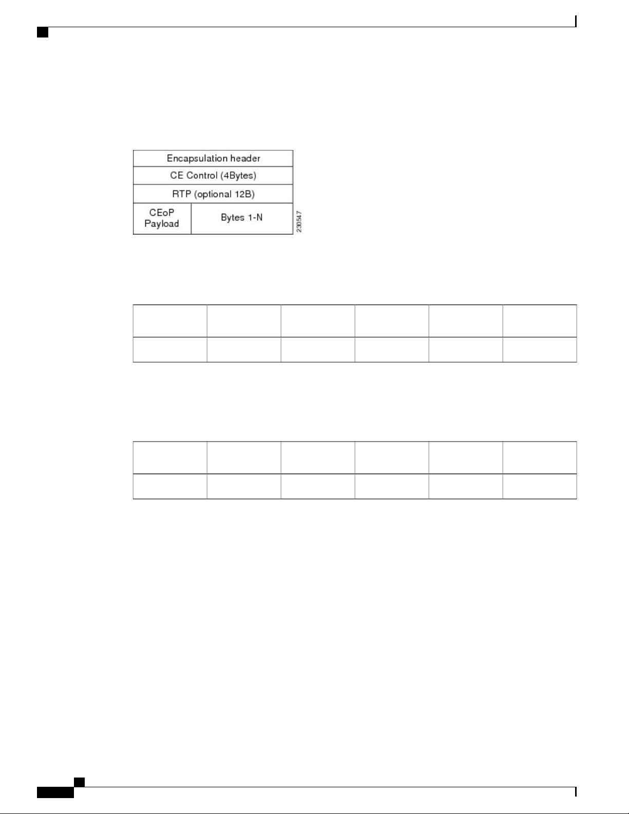
In SAToP mode the interface is considered as a continuous framed bit stream. The packetization of the stream
is done according to IETF RFC 4553. All signaling is carried out transparently as a part of a bit stream. Figure
Time Division Multiplexing Configuration Guide, Cisco IOS XE Fuji 16.7.x (Cisco ASR 900 Series)
3
Page 12
Circuit Emulation Service over Packet-Switched Network
1: Unstructured SAToP Mode Frame Format, on page 4 shows the frame format in Unstructured SAToP
mode.
Figure 1: Unstructured SAToP Mode Frame Format
Table 1: SAToP T1 Frame: Payload and Jitter Limits, on page 4 shows the payload and jitter limits for the
T1 lines in the SAToP frame format.
Table 1: SAToP T1 Frame: Payload and Jitter Limits
Configuring Pseudowire
Minimum JitterMaximum JitterMaximum
Payload
Payload
Table 2: SAToP E1 Frame: Payload and Jitter Limits, on page 4 shows the payload and jitter limits for the
E1 lines in the SAToP frame format.
Table 2: SAToP E1 Frame: Payload and Jitter Limits
Minimum JitterMaximum JitterMaximum
Payload
Payload
For instructions on how to configure SAToP, see Configuring Structure-Agnostic TDM over Packet (SAToP),
on page 21.
Circuit Emulation Service over Packet-Switched Network
CESoPSN encapsulates structured TDM signals as PWs over public switched networks (PSNs). It complements
similar work for structure-agnostic emulation of TDM bit streams, such as SAToP. Emulation of circuits saves
PSN bandwidth and supports DS0-level grooming and distributed cross-connect applications. It also enhances
resilience of CE devices due to the effects of loss of packets in the PSN.
CESoPSN identifies framing and sends only the payload, which can either be channelized T1s within DS3 or
DS0s within T1. DS0s can be bundled to the same packet. The CESoPSN mode is based on IETF RFC 5086.
Each supported interface can be configured individually to any supported mode. The supported services
comply with IETF and ITU drafts and standards.
Minimum JitterMaximum JitterMinimum
26419210320960
Minimum JitterMaximum JitterMinimum
264256103201280
Time Division Multiplexing Configuration Guide, Cisco IOS XE Fuji 16.7.x (Cisco ASR 900 Series)
4
Page 13
Configuring Pseudowire
Circuit Emulation Service over Packet-Switched Network
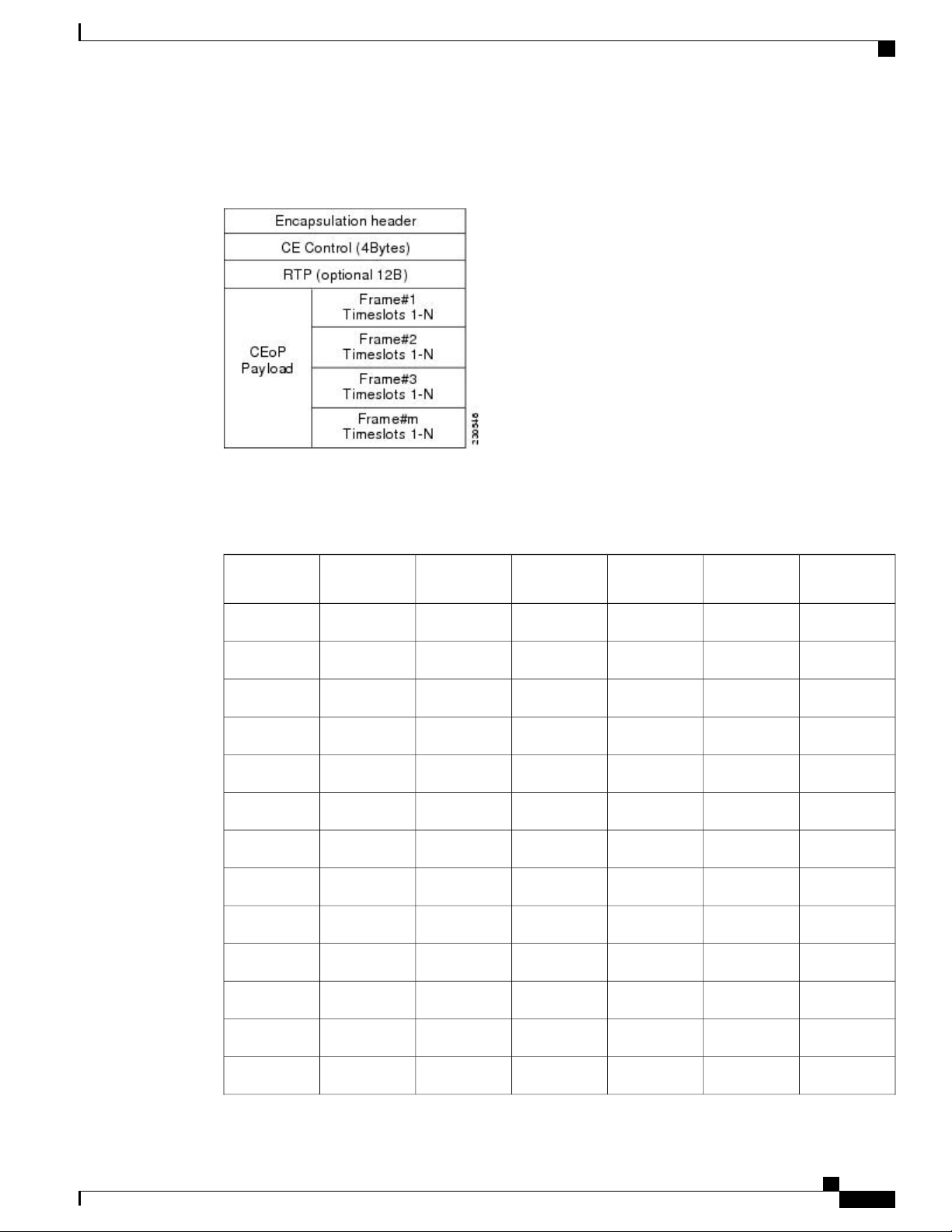
Figure 2: Structured CESoPSN Mode Frame Format, on page 5 shows the frame format in CESoPSN mode.
Figure 2: Structured CESoPSN Mode Frame Format
Table 3: CESoPSN DS0 Lines: Payload and Jitter Limits, on page 5 shows the payload and jitter for the
DS0 lines in the CESoPSN mode.
Table 3: CESoPSN DS0 Lines: Payload and Jitter Limits
DS0
Maximum
Payload
Maximum
Jitter
Minimum
Jitter
Minimum
Payload
Maximum
Jitter
Minimum
Jitter
82563210320401
41283210320802
412833103201203
26432103201604
26440103202005
26448103202406
26456103202807
26464103203208
26472103203609
264801032040010
264881032044011
264961032048012
2641041032052013
Time Division Multiplexing Configuration Guide, Cisco IOS XE Fuji 16.7.x (Cisco ASR 900 Series)
5
Page 14

Asynchronous Transfer Mode over MPLS
Configuring Pseudowire
DS0
Maximum
Payload
Maximum
Jitter
Minimum
Jitter
Minimum
Payload
Maximum
Jitter
Minimum
Jitter
2641121032056014
2641201032060015
2641281032064016
2641361032068017
2641441032072018
2641521032076019
2641601032080020
2641681032084021
2641761032088022
2641841032092023
2641921032096024
For instructions on how to configure SAToP, see Configuring Structure-Agnostic TDM over Packet (SAToP),
on page 21.
Asynchronous Transfer Mode over MPLS
An ATM over MPLS (AToM) PW is used to carry Asynchronous Transfer Mode (ATM) cells over an MPLS
network. It is an evolutionary technology that allows you to migrate packet networks from legacy networks,
26420010320100025
26420810320104026
26421610320108027
26422410320112028
26423210320116029
26424010320120030
26424810320124031
26425610320128032
Time Division Multiplexing Configuration Guide, Cisco IOS XE Fuji 16.7.x (Cisco ASR 900 Series)
6
Page 15

Configuring Pseudowire
Transportation of Service Using Ethernet over MPLS
while providing transport for legacy applications. AToM is particularly useful for transporting 3G voice traffic
over MPLS networks.
You can configure AToM in the following modes:
• N-to-1 Cell—Maps one or more ATM virtual channel connections (VCCs) or virtual permanent connection
(VPCs) to a single pseudowire.
• 1-to-1 Cell—Maps a single ATM VCC or VPC to a single pseudowire.
• Port—Maps a single physical port to a single pseudowire connection.
The Cisco ASR 903 Series Router also supports cell packing and PVC mapping for AToM pseudowires.
This release does not support AToM N-to-1 Cell Mode or 1-to-1 Cell Mode.Note
For more information about how to configure AToM, see Configuring an ATM over MPLS Pseudowire, on
page 26.
Transportation of Service Using Ethernet over MPLS
Ethernet over MPLS (EoMPLS) PWs provide a tunneling mechanism for Ethernet traffic through an
MPLS-enabled Layer 3 core network. EoMPLS PWs encapsulate Ethernet protocol data units (PDUs) inside
MPLS packets and use label switching to forward them across an MPLS network. EoMPLS PWs are an
evolutionary technology that allows you to migrate packet networks from legacy networks while providing
transport for legacy applications. EoMPLS PWs also simplify provisioning, since the provider edge equipment
only requires Layer 2 connectivity to the connected customer edge (CE) equipment. The Cisco ASR 903
Series Router implementation of EoMPLS PWs is compliant with the RFC 4447 and 4448 standards.
The Cisco ASR 903 Series Router supports VLAN rewriting on EoMPLS PWs. If the two networks use
different VLAN IDs, the router rewrites PW packets using the appropriate VLAN number for the local network.
For instructions on how to create an EoMPLS PW, see Configuring an Ethernet over MPLS Pseudowire, on
page 37.
Limitations
If you are running Cisco IOS XE Release 3.17S, the following limitation applies:
BGP PIC with TDM Pseudowire is supported only on the ASR 900 router with RSP1 module.
•
If you are running Cisco IOS XE Release 3.17S and later releases, the following limitations apply:
Channel associated signaling (CAS) is not supported on the T1/E1 and OC-3 interface modules on the
•
router.
BGP PIC is not supported for MPLS/LDP over MLPPP and POS in the core.
•
BGP PIC is not supported for Multi-segment Pseudowire or Pseudowire switching.
•
BGP PIC is not supported for VPLS and H-VPLS
•
.
Time Division Multiplexing Configuration Guide, Cisco IOS XE Fuji 16.7.x (Cisco ASR 900 Series)
7
Page 16

Configuring CEM
Configuring Pseudowire
BGP PIC is not supported for IPv6.
•
If BGP PIC is enabled, Multi-hop BFD should not be configured using the bfd neighbor fall-overr bfd
•
command.
If BGP PIC is enabled, neighbor ip-address weight weight command should not be configured.
•
If BGP PIC is enabled, bgp nexthop trigger delay 6 under the address-family ipv4 command and bgp
•
nexthop trigger delay 7 under the address-family vpnv4 command should be configured. For
information on the configuration examples for BGP PIC–TDM, see Example: BGP PIC with TDM-PW
Configuration, on page 46.
If BGP PIC is enabled and the targeted LDP for VPWS cross-connect services are established over BGP,
•
perform the following tasks:
configure Pseudowire-class (pw-class) with encapsulation "mpls"
◦
configure no status control-plane route-watch under the pw-class
◦
associate the pw-class with the VPWS cross-connect configurations
◦
If you are running Cisco IOS-XE 3.18S, the following restrictions apply for BGP PIC with MPLS TE for
TDM Pseudowire:
MPLS TE over MLPPP and POS in the core is not supported.
•
Co-existence of BGP PIC with MPLS Traffic Engineering Fast Reroute (MPLS TE FRR) is not supported.
•
Configuring CEM
This section provides information about how to configure CEM. CEM provides a bridge between a time-division
multiplexing (TDM) network and a packet network, such as Multiprotocol Label Switching (MPLS). The
router encapsulates the TDM data in the MPLS packets and sends the data over a CEM pseudowire to the
remote provider edge (PE) router. Thus, function as a physical communication link across the packet network.
The following sections describe how to configure CEM:
Note
Configuration Guidelines and Restrictions
Steps for configuring CEM features are also included in the Configuring Structure-Agnostic TDM over
Packet (SAToP), on page 21 and Configuring Circuit Emulation Service over Packet-Switched Network
(CESoPSN), on page 23 sections.
Not all combinations of payload size and dejitter buffer size are supported. If you apply an incompatible
payload size or dejitter buffer size configuration, the router rejects it and reverts to the previous configuration.
Configuring a CEM Group
The following section describes how to configure a CEM group on the Cisco ASR 903 Series Router.
Time Division Multiplexing Configuration Guide, Cisco IOS XE Fuji 16.7.x (Cisco ASR 900 Series)
8
Page 17

Configuring Pseudowire
SUMMARY STEPS
DETAILED STEPS
enable
1.
configure terminal
2.
controller {t1 | e1} slot/subslot/port
3.
cem-group group-number {unframed | timeslots timeslot}
4.
end
5.
PurposeCommand or Action
Configuring a CEM Group
Step 1
Step 2
Step 3
Step 4
Example:
Router> enable
Example:
Router# configure terminal
controller {t1 | e1} slot/subslot/port
Example:
Router(config)# controller t1 1/0
cem-group group-number {unframed |
timeslots timeslot}
Example:
Router(config-controller)# cem-group
6 timeslots 1-4,9,10
Enables privileged EXEC mode.enable
Enter your password if prompted.
•
Enters global configuration mode.configure terminal
Enters controller configuration mode.
Use the slot and port arguments to specify the slot number and port
•
number to be configured.
Note
The slot number is always
0.
Creates a circuit emulation channel from one or more time slots of a T1 or
E1 line.
The group-number keyword identifies the channel number to be
•
used for this channel. For T1 ports, the range is 0 to 23. For E1 ports,
the range is 0 to 30.
Use the unframed keyword to specify that a single CEM channel is
•
being created including all time slots and the framing structure of the
line.
Step 5
Example:
Router(config-controller)# end
Time Division Multiplexing Configuration Guide, Cisco IOS XE Fuji 16.7.x (Cisco ASR 900 Series)
Use the timeslots keyword and the timeslot argument to specify the
•
time slots to be included in the CEM channel. The list of time slots
may include commas and hyphens with no spaces between the
numbers.
Exits controller configuration mode and returns to privileged EXEC mode.end
9
Page 18

Using CEM Classes
Using CEM Classes
A CEM class allows you to create a single configuration template for multiple CEM pseudowires. Follow
these steps to configure a CEM class:
Configuring Pseudowire
Note
SUMMARY STEPS
DETAILED STEPS
The CEM parameters at the local and remote ends of a CEM circuit must match; otherwise, the pseudowire
between the local and remote PE routers will not come up.
You cannot apply a CEM class to other pseudowire types such as ATM over MPLS.Note
enable
1.
configure terminal
2.
class cem cem-class
3.
payload-size size | dejitter-buffer buffer-size | idle-pattern pattern
4.
exit
5.
interface cem slot/subslot
6.
exit
7.
exit
8.
PurposeCommand or Action
Step 1
Step 2
Step 3
10
Enables privileged EXEC mode.enable
Enter your password if prompted.
Example:
Router> enable
•
Enters global configuration mode.configure terminal
Example:
Router# configure terminal
class cem cem-class
Example:
Router(config)# class cem mycemclass
Time Division Multiplexing Configuration Guide, Cisco IOS XE Fuji 16.7.x (Cisco ASR 900 Series)
Creates a new CEM class
Page 19

Configuring Pseudowire
Using CEM Classes
PurposeCommand or Action
Step 4
Step 5
Step 6
payload-size size | dejitter-buffer buffer-size | idle-pattern
pattern
Example:
Router(config-cem-class)# payload-size 512
Example:
Router(config-cem-class)# dejitter-buffer 10
Example:
Router(config-cem-class)# idle-pattern 0x55
Example:
Router(config-cem-class)# exit
interface cem slot/subslot
Example:
Example:
Enter the configuration commands common to the
CEM class. This example specifies a sample rate,
payload size, dejitter buffer, and idle pattern.
Returns to the config prompt.exit
Configure the CEM interface that you want to use for
the new CEM class.
Note
The use of the xconnect command can vary
depending on the type of pseudowire you
are configuring.
Router(config)# interface cem 0/0
Example:
Router(config-if)# no ip address
Example:
Router(config-if)# cem 0
Example:
Router(config-if-cem)# cem class mycemclass
Example:
Router(config-if-cem)# xconnect 10.10.10.10 200
encapsulation mpls
Example:
Time Division Multiplexing Configuration Guide, Cisco IOS XE Fuji 16.7.x (Cisco ASR 900 Series)
11
Page 20

Configuring a Clear-Channel ATM Interface
Configuring Pseudowire
PurposeCommand or Action
Step 7
Example:
Router(config-if-cem)# exit
Example:
Step 8
Example:
Router(config-if)# exit
Example:
Configuring a Clear-Channel ATM Interface
Configuring CEM Parameters
Exits the CEM interface.exit
Exits configuration mode.exit
The following sections describe the parameters you can configure for CEM circuits.
Note
The CEM parameters at the local and remote ends of a CEM circuit must match; otherwise, the pseudowire
between the local and remote PE routers will not come up.
Configuring Payload Size (Optional)
To specify the number of bytes encapsulated into a single IP packet, use the pay-load size command. The size
argument specifies the number of bytes in the payload of each packet. The range is from 32 to 1312 bytes.
Default payload sizes for an unstructured CEM channel are as follows:
E1 = 256 bytes
•
T1 = 192 bytes
•
DS0 = 32 bytes
•
Default payload sizes for a structured CEM channel depend on the number of time slots that constitute the
channel. Payload size (L in bytes), number of time slots (N), and packetization delay (D in milliseconds) have
the following relationship: L = 8*N*D. The default payload size is selected in such a way that the packetization
Time Division Multiplexing Configuration Guide, Cisco IOS XE Fuji 16.7.x (Cisco ASR 900 Series)
12
Page 21

Configuring Pseudowire
delay is always 1 millisecond. For example, a structured CEM channel of 16xDS0 has a default payload size
of 128 bytes.
The payload size must be an integer of the multiple of the number of time slots for structured CEM channels.
Setting the Dejitter Buffer Size
To specify the size of the dejitter buffer used to compensate for the network filter, use the dejitter-buffer size
command. The configured dejitter buffer size is converted from milliseconds to packets and rounded up to
the next integral number of packets. Use the size argument to specify the size of the buffer, in milliseconds.
The range is from 1 to 32 ms; the default is 5 ms.
Setting an Idle Pattern (Optional)
To specify an idle pattern, use the [no] idle-pattern pattern1 command. The payload of each lost CESoPSN
data packet must be replaced with the equivalent amount of the replacement data. The range for pattern is
from 0x0 to 0xFF; the default idle pattern is 0xFF.
Configuring CEM Parameters
Enabling Dummy Mode
Dummy mode enables a bit pattern for filling in for lost or corrupted frames. To enable dummy mode, use
the dummy-mode [last-frame | user-defined] command. The default is last-frame. The following is an
example:
Router(config-cem)# dummy-mode last-frame
Setting a Dummy Pattern
If dummy mode is set to user-defined, you can use the dummy-pattern pattern command to configure the
dummy pattern. The range for pattern is from 0x0 to 0xFF. The default dummy pattern is 0xFF. The following
is an example:
Router(config-cem)# dummy-pattern 0x55
Note
The dummy-pattern command is not supported on the following interface modules:
48-Port T3/E3 CEM interface module
•
48-Port T1/E1 CEM interface module
•
1-port OC-192 Interface module or 8-port Low Rate interface module
•
Shutting Down a CEM Channel
To shut down a CEM channel, use the shutdown command in CEM configuration mode. The shutdown
command is supported only under CEM mode and not under the CEM class.
Time Division Multiplexing Configuration Guide, Cisco IOS XE Fuji 16.7.x (Cisco ASR 900 Series)
13
Page 22

Configuring CAS
Configuring CAS
This section provides information about how to configure Channel Associated Signaling (CAS).
Information About CAS
The CAS is a method of signaling, where the signaling information is carried over a signaling resource that
is specific to a particular channel. For each channel there is a dedicated and associated signaling channel.
The Cisco ASR Router with RSP2 module supports CAS with 8-port T1/E1 interface modules and is
interoperable with 6-port Ear and Mouth (E&M) interface modules.
Configuring Pseudowire
Note
The Cisco ASR Router supports CAS only in the E1 mode for the 8-port T1/E1 interface cards. Use the
card type e1 slot/subslot command to configure controller in the E1 mode.
In the E1 framing and signaling, each E1 frame supports 32 timeslots or channels. From the available timeslots,
the timeslot 17 is used for signaling information and the remaining timeslots are used for voice and data.
Hence, this kind of signaling is often referred as CAS.
In the E1 frame, the timeslots are numbered from 1 to 32, where the timeslot 1 is used for frame synchronization
and is unavailable for traffic. When the first E1 frame passes through the controller, the first four bits of
signaling channel (timeslot 17) are associated with the timeslot 2 and the second four bits are associated with
the timeslot 18. In the second E1 frame, the first four bits carry signaling information for the timeslot 3 and
the second four bits for the timeslot 19.
Configuring CAS
To configure CAS on the controller interface, perform the following steps:
SUMMARY STEPS
1.
2.
3.
4.
5.
6.
configure terminal
controller e1 slot/subslot/port
cas
clock source internal
cem-group group-numbertimeslots time-slot-range
end
Time Division Multiplexing Configuration Guide, Cisco IOS XE Fuji 16.7.x (Cisco ASR 900 Series)
14
Page 23

Configuring Pseudowire
DETAILED STEPS
Configuring CAS
PurposeCommand or Action
Step 1
Step 2
Step 3
Step 4
Step 5
Example:
Router# configure terminal
controller e1 slot/subslot/port
Example:
Router(config)# controller E1 0/4/2
Example:
Router(config-controller)# cas
Example:
Router(config-controller)# clock source
internal
cem-group group-numbertimeslots
time-slot-range
Enters the global configuration mode.configure terminal
Enters controller configuration mode to configure the E1 interface.
Note
The CAS is supported only in the El mode. Use the card type
e1 slot/subslot command to configure controller in the E1
mode.
Configures CAS on the interface.cas
Sets the clocking for individual E1 links.clock source internal
Creates a Circuit Emulation Services over Packet Switched Network
circuit emulation (CESoPSN) CEM group.
Step 6
Example:
Router(config-controller)# cem-group
0 timeslots 1-31
Example:
Router(config-controller)# end
• cem-group—Creates a circuit emulation (CEM) channel from one
or more time slots of a E1 line.
• group-number—CEM identifier to be used for this group of time
slots. For E1 ports, the range is from 0 to 30.
• timeslots—Specifies that a list of time slots is to be used as
specified by the time-slot-range argument.
• time-slot-range—Specifies the time slots to be included in the
CEM channel. The list of time slots may include commas and
hyphens with no spaces between the numbers.
Exits the controller session and returns to the configuration mode.end
Time Division Multiplexing Configuration Guide, Cisco IOS XE Fuji 16.7.x (Cisco ASR 900 Series)
15
Page 24

Verifying CAS Configuration
What to Do Next
You can configure CEM interface and parameters such as xconnect.
Verifying CAS Configuration
Use the show cem circuit cem-group-id command to display CEM statistics for the configured CEM circuits.
If xconnect is configured under the circuit, the command output also includes information about the attached
circuit.
Following is a sample output of the show cem circuit command to display the detailed information about
CEM circuits configured on the router:
Router# show cem circuit 0
CEM0/3/0, ID: 0, Line: UP, Admin: UP, Ckt: ACTIVE
Controller state: up, T1/E1 state: up
Idle Pattern: 0xFF, Idle CAS: 0x8
Dejitter: 8 (In use: 0)
Payload Size: 32
Framing: Framed (DS0 channels: 1)
CEM Defects Set
None
Signalling: No CAS
RTP: No RTP
Ingress Pkts: 5001 Dropped: 0
Egress Pkts: 5001 Dropped: 0
CEM Counter Details
Input Errors: 0 Output Errors: 0
Pkts Missing: 0 Pkts Reordered: 0
Misorder Drops: 0 JitterBuf Underrun: 0
Error Sec: 0 Severly Errored Sec: 0
Unavailable Sec: 0 Failure Counts: 0
Pkts Malformed: 0 JitterBuf Overrun: 0
Configuring Pseudowire
Note
The show cem circuit command displays No CAS for the Signaling field. The No CAS is displayed since
CAS is not enabled at the CEM interface level. The CAS is enabled for the entire port and you cannot
enable or disable CAS at the CEM level. To view the CAS configuration, use the show running-config
command.
Configuration Examples for CAS
The following example shows how to configure CAS on a CEM interface on the router:
Router# configure terminal
Router(config)# controller E1 0/4/2
Router(config-controller)# cas
Router(config-controller)# clock source internal
Router(config-controller)# cem-group 0 timeslots 1
Router(config-controller)# exit
Time Division Multiplexing Configuration Guide, Cisco IOS XE Fuji 16.7.x (Cisco ASR 900 Series)
16
Page 25

Configuring Pseudowire
Configuring ATM
The following sections describe how to configure ATM features on the T1/E1 interface module:
Configuring a Clear-Channel ATM Interface
To configure the T1 interface module for clear-channel ATM, follow these steps:
SUMMARY STEPS
enable
1.
configure terminal
2.
controller {t1} slot/subslot/port
3.
atm
4.
end
5.
Configuring ATM
DETAILED STEPS
Step 1
Step 2
Step 3
Step 4
Step 5
Example:
Router> enable
Example:
Router# configure terminal
controller {t1} slot/subslot/port
Example:
Router(config)# controller t1 0/3/0
atm
Example:
Router(config-controller)# atm
PurposeCommand or Action
Enables privileged EXEC mode.enable
Enter your password if prompted.
•
Enters global configuration mode.configure terminal
Selects the T1 controller for the port you are configuring (where
slot /subslot identifies the location and /port identifies the port).
Configures the port (interface) for clear-channel ATM. The router
creates an ATM interface whose format is atm/slot /subslot /port
.
Note
The slot number is always
0.
Exits configuration mode.end
Example:
Router(config-controller)# end
Time Division Multiplexing Configuration Guide, Cisco IOS XE Fuji 16.7.x (Cisco ASR 900 Series)
17
Page 26

Configuring ATM IMA
What to Do Next
To access the new ATM interface, use the interface atmslot/subslot/port command.
This configuration creates an ATM interface that you can use for a clear-channel pseudowire and other features.
For more information about configuring pseudowires, see Configuring Pseudowire, on page 1
Configuring ATM IMA
Inverse multiplexing provides the capability to transmit and receive a single high-speed data stream over
multiple slower-speed physical links. In Inverse Multiplexing over ATM (IMA), the originating stream of
ATM cells is divided so that complete ATM cells are transmitted in round-robin order across the set of ATM
links. Follow these steps to configure ATM IMA on the Cisco ASR 903 Series Router.
Configuring Pseudowire
Note
SUMMARY STEPS
ATM IMA is used as an element in configuring ATM over MPLS pseudowires. For more information
about configuring pseudowires, see Configuring Pseudowire, on page 1
The maximum ATM over MPLS pseudowires supported per T1/E1 interface module is 500.Note
To configure the ATM interface on the router, you must install the ATM feature license using the license
install atm command. To activate or enable the configuration on the IMA interface after the ATM license is
installed, use the license feature atm command.
For more information about installing licenses, see the Software Activation Configuration Guide, Cisco IOS
XE Release 3S.
You can create a maximum of 16 IMA groups on each T1/E1 interface module.Note
enable
1.
configure terminal
2.
card type {t1 | e1} slot [bay]
3.
controller {t1 | e1} slot/subslot/port
4.
clock source internal
5.
ima group group-number
6.
exit
7.
interface ATMslot/subslot/IMA group-number
8.
no ip address
9.
atm bandwidth dynamic
10.
no atm ilmi-keepalive
11.
exit
12.
Time Division Multiplexing Configuration Guide, Cisco IOS XE Fuji 16.7.x (Cisco ASR 900 Series)
18
Page 27

Configuring Pseudowire
DETAILED STEPS
Configuring ATM IMA
PurposeCommand or Action
Step 1
Step 2
Step 3
Step 4
Step 5
Example:
Router> enable
Example:
Router# configure terminal
card type {t1 | e1} slot [bay]
Example:
Router(config)# card type e1 0 0
controller {t1 | e1} slot/subslot/port
Example:
Router(config)# controller e1 0/0/4
Example:
Enables privileged EXEC mode.enable
Enter your password if prompted.
•
Enters global configuration mode.configure terminal
Specifies the slot and port number of the E1 or T1 interface.
Specifies the controller interface on which you want to enable IMA.
Sets the clock source to internal.clock source internal
Step 6
Step 7
Example:
Router(config-controller)# clock source
internal
Example:
ima group group-number
Example:
Router(config-controller)# ima-group 0
scrambling-payload
Example:
Example:
Router(config-controller)# exit
Assigns the interface to an IMA group, and set the
scrambling-payload parameter to randomize the ATM cell payload
frames. This command assigns the interface to IMA group 0.
Note
To add another member link, repeat Step 3 to Step 6 .
This command automatically creates an ATM0/IMAx
interface.
Exits the controller interface.exit
Time Division Multiplexing Configuration Guide, Cisco IOS XE Fuji 16.7.x (Cisco ASR 900 Series)
19
Page 28

Configuring ATM IMA
Example:
Configuring Pseudowire
PurposeCommand or Action
Step 8
Step 9
Step 10
interface ATMslot/subslot/IMA group-number
Example:
Router(config-if)# interface atm0/1/ima0
Example:
Router(config-if)# no ip address
Example:
Specify the slot location and port of IMA interface group.
• slot—The location of the ATM IMA interface module.
• group-number—The IMA group.
The example specifies the slot number as 0 and the group number
as 0.
Note
To explicitly configure the IMA group ID for the IMA
interface, use the optional ima group-id command. You
cannot configure the same IMA group ID on two different
IMA interfaces; therefore, if you configure an IMA group
ID with the system-selected default ID already configured
on an IMA interface, the system toggles the IMA interface
to make the user-configured IMA group ID the effective
IMA group ID. The system toggles the original IMA
interface to select a different IMA group ID.
Disables the IP address configuration for the physical layer interface.no ip address
Specifies the ATM bandwidth as dynamic.atm bandwidth dynamic
Step 11
Step 12
20
Router(config-if)# atm bandwidth dynamic
no atm ilmi-keepalive
Disables the Interim Local Management Interface (ILMI) keepalive
parameters.
Example:
Router(config-if)# no atm ilmi-keepalive
Exits configuration mode.exit
Example:
Router(config)# exit
What to Do Next
The above configuration has one IMA shorthaul with two member links (atm0/0 and atm0/1).
Time Division Multiplexing Configuration Guide, Cisco IOS XE Fuji 16.7.x (Cisco ASR 900 Series)
Page 29

Configuring Pseudowire
BGP PIC with TDM Configuration
BGP PIC with TDM Configuration
To configure the TDM pseudowires on the router, see Configuring CEM, on page 8.
To configure BGP PIC on the router, see IP Routing: BGP Configuration Guide, Cisco IOS XE Release 3S
(Cisco ASR 900 Series).
See the configuration example, Example: BGP PIC with TDM Configuration, on page 45.
Configuring Structure-Agnostic TDM over Packet (SAToP)
Follow these steps to configure SAToP on the Cisco ASR 903 Series Router:
SUMMARY STEPS
enable
1.
configure terminal
2.
controller [t1|e1] slot/sublot
3.
cem-group group-number {unframed | timeslots timeslot}
4.
interface cem slot/subslot
5.
xconnect ip_address encapsulation mpls
6.
exit
7.
DETAILED STEPS
Step 1
Step 2
Step 3
Step 4
Example:
Router> enable
Example:
Router# configure terminal
controller [t1|e1] slot/sublot
Example:
Router(config-controller)# controller t1 0/4
cem-group group-number {unframed | timeslots
timeslot}
Example:
Router(config-if)# cem-group 4 unframed
PurposeCommand or Action
Enables privileged EXEC mode.enable
Enter your password if prompted.
•
Enters global configuration mode.configure terminal
Configures the T1 or E1 interface.
Assigns channels on the T1 or E1 circuit to the CEM
channel. This example uses the unframed parameter to
assign all the T1 timeslots to the CEM channel.
Time Division Multiplexing Configuration Guide, Cisco IOS XE Fuji 16.7.x (Cisco ASR 900 Series)
21
Page 30

Configuring Structure-Agnostic TDM over Packet (SAToP)
Configuring Pseudowire
PurposeCommand or Action
Step 5
Step 6
Step 7
interface cem slot/subslot
Example:
Router(config)# interface CEM 0/4
Example:
Router(config-if)# no ip address
Example:
Router(config-if)# cem 4
xconnect ip_address encapsulation mpls
Example:
Router(config-if)# xconnect 10.10.2.204
encapsulation mpls
Example:
Router(config)# exit
Defines a CEM group.
Binds an attachment circuit to the CEM interface to create
a pseudowire. This example creates a pseudowire by
binding the CEM circuit 304 to the remote peer
10.10.2.204.
Exits configuration mode.exit
Note
What to Do Next
When creating IP routes for a pseudowire configuration, we recommend that you build a route from the
cross-connect address (LDP router-id or loopback address) to the next hop IP address, such as ip route
10.10.10.2 255.255.255.254 10.2.3.4.
Time Division Multiplexing Configuration Guide, Cisco IOS XE Fuji 16.7.x (Cisco ASR 900 Series)
22
Page 31

Configuring Pseudowire
Configuring Circuit Emulation Service over Packet-Switched Network (CESoPSN)
Configuring Circuit Emulation Service over Packet-Switched
Network (CESoPSN)
SUMMARY STEPS
enable
1.
configure terminal
2.
controller [e1 | t1] slot/subslot
3.
cem-group group-number timselots timeslots
4.
exit
5.
interface cem slot/subslot
6.
xconnect ip_address encapsulation mpls
7.
exit
8.
exit
9.
DETAILED STEPS
Step 1
Step 2
Step 3
Step 4
Example:
Router> enable
Example:
Router# configure terminal
controller [e1 | t1] slot/subslot
Example:
Router(config)# controller e1 0/0
Example:
cem-group group-number timselots timeslots
Example:
PurposeCommand or Action
Enables privileged EXEC mode.enable
Enter your password if prompted.
•
Enters global configuration mode.configure terminal
Enters configuration mode for the E1 or T1 controller.
Assigns channels on the T1 or E1 circuit to the circuit
emulation (CEM) channel. This example uses the timeslots
parameter to assign specific timeslots to the CEM channel.
Router(config-controller)# cem-group 5
timeslots 1-24
Time Division Multiplexing Configuration Guide, Cisco IOS XE Fuji 16.7.x (Cisco ASR 900 Series)
23
Page 32

Configuring a Clear-Channel ATM Pseudowire
Configuring Pseudowire
PurposeCommand or Action
Step 5
Step 6
Step 7
Step 8
Example:
Router(config-controller)# exit
interface cem slot/subslot
Example:
Router(config)# interface CEM0/5
Example:
Router(config-if-cem)# cem 5
Example:
xconnect ip_address encapsulation mpls
Example:
Router(config-if)# xconnect 10.10.2.204
encapsulation mpls
Exits controller configuration.exit
Defines a CEM channel.
Binds an attachment circuit to the CEM interface to create
a pseudowire. This example creates a pseudowire by
binding the CEM circuit 304 to the remote peer
10.10.2.204.
Exits the CEM interface.exit
Example:
Router(config-if-cem)# exit
Step 9
Example:
Router(config)# exit
Exits configuration mode.exit
Configuring a Clear-Channel ATM Pseudowire
To configure the T1 interface module for clear-channel ATM, follow these steps:
Time Division Multiplexing Configuration Guide, Cisco IOS XE Fuji 16.7.x (Cisco ASR 900 Series)
24
Page 33

Configuring Pseudowire
SUMMARY STEPS
DETAILED STEPS
Configuring a Clear-Channel ATM Pseudowire
controller {t1} slot/subslot/port
1.
atm
2.
exit
3.
interface atm slot/subslot/port
4.
pvc vpi/vci
5.
xconnect peer-router-id vcid {encapsulation mpls | pseudowire-class name
6.
end
7.
PurposeCommand or Action
Step 1
Step 2
Step 3
Step 4
Step 5
controller {t1} slot/subslot/port
Example:
Router(config)# controller t1 0/4
atm
Example:
Router(config-controller)# atm
Example:
Router(config-controller)# exit
interface atm slot/subslot/port
Example:
Router(config)# interface atm 0/3/0
pvc vpi/vci
Example:
Selects the T1 controller for the port you are configuring.
Note
The slot number is always
0.
Configures the port (interface) for clear-channel ATM. The
router creates an ATM interface whose format is atm/slot
/subslot /port .
Note
The slot number is always
0.
Returns you to global configuration mode.exit
Selects the ATM interface in Step 2 .
Configures a PVC for the interface and assigns the PVC a
VPI and VCI. Do not specify 0 for both the VPI and VCI.
Step 6
Router(config-if)# pvc 0/40
xconnect peer-router-id vcid {encapsulation mpls
| pseudowire-class name
Example:
Router(config-if)# xconnect 10.10.2.204 200
encapsulation mpls
Time Division Multiplexing Configuration Guide, Cisco IOS XE Fuji 16.7.x (Cisco ASR 900 Series)
Configures a pseudowire to carry data from the clear-channel
ATM interface over the MPLS network.
25
Page 34

Configuring an ATM over MPLS Pseudowire
Configuring Pseudowire
PurposeCommand or Action
Step 7
Example:
Router(config-if)# end
Exits configuration mode.end
Configuring an ATM over MPLS Pseudowire
ATM over MPLS pseudowires allow you to encapsulate and transport ATM traffic across an MPLS network.
This service allows you to deliver ATM services over an existing MPLS network.
The following sections describe how to configure transportation of service using ATM over MPLS:
Configuring the Controller, on page 26
•
Configuring an IMA Interface, on page 27
•
Configuring the ATM over MPLS Pseudowire Interface, on page 29
•
Configuring the Controller
SUMMARY STEPS
DETAILED STEPS
Step 1
Example:
Router> enable
enable
1.
configure terminal
2.
card type {e1} slot/subslot
3.
controller {e1} slot/subslot
4.
clock source {internal | line}
5.
ima-group group-number scrambling-payload
6.
exit
7.
PurposeCommand or Action
Enables privileged EXEC mode.enable
Enter your password if prompted.
•
Time Division Multiplexing Configuration Guide, Cisco IOS XE Fuji 16.7.x (Cisco ASR 900 Series)
26
Page 35

Configuring Pseudowire
Configuring an IMA Interface
PurposeCommand or Action
Step 2
Step 3
Step 4
Step 5
Step 6
Example:
Router# configure terminal
card type {e1} slot/subslot
Example:
Router(config)# card type e1 0 0
controller {e1} slot/subslot
Example:
Router(config)# controller e1 0/4
Example:
Router(config-controller)# clock source
internal
ima-group group-number scrambling-payload
Example:
Router(config-controller)# ima-group 0
scrambling-payload
Enters global configuration mode.configure terminal
Configures IMA on an E1 or T1 interface.
Specifies the controller interface on which you want to enable
IMA.
Sets the clock source to internal.clock source {internal | line}
If you want to configure an ATM IMA backhaul, use the
ima-group command to assign the interface to an IMA group.
For a T1 connection, use the no-scrambling-payload to disable
ATM-IMA cell payload scrambling; for an E1 connection, use
the scrambling-payload parameter to enable ATM-IMA cell
payload scrambling.
The example assigns the interface to IMA group 0 and enables
payload scrambling.
Step 7
Example:
Router(config)# exit
Configuring an IMA Interface
If you want to use ATM IMA backhaul, follow these steps to configure the IMA interface.
You can create a maximum of 16 IMA groups on each T1/E1 interface module.Note
Time Division Multiplexing Configuration Guide, Cisco IOS XE Fuji 16.7.x (Cisco ASR 900 Series)
Exits configuration mode.exit
27
Page 36

Configuring an IMA Interface
SUMMARY STEPS
DETAILED STEPS
enable
1.
configure terminal
2.
interface ATM slot / IMA group-number
3.
no ip address
4.
atm bandwidth dynamic
5.
no atm ilmi-keepalive
6.
exit
7.
Configuring Pseudowire
PurposeCommand or Action
Step 1
Step 2
Step 3
Step 4
Example:
Router> enable
Example:
Router# configure terminal
interface ATM slot / IMA group-number
Example:
Router(config-controller)# interface
atm0/ima0
Example:
Router(config-if)#
Enables privileged EXEC mode.enable
Enter your password if prompted.
•
Enters global configuration mode.configure terminal
Specifies the slot location and port of IMA interface group. The syntax
is as follows:
• slot—The slot location of the interface module.
• group-number—The group number of the IMA group.
The example specifies the slot number as 0 and the group number as 0.
Note
To explicitly configure the IMA group ID for the IMA interface,
you may use the optional ima group-id command. You cannot
configure the same IMA group ID on two different IMA
interfaces; therefore, if you configure an IMA group ID with
the system-selected default ID already configured on an IMA
interface, the system toggles the IMA interface to make the
user-configured IMA group ID the effective IMA group ID. At
the same, the system toggles the original IMA interface to select
a different IMA group ID.
Disables the IP address configuration for the physical layer interface.no ip address
Example:
Router(config-if)# no ip address
Time Division Multiplexing Configuration Guide, Cisco IOS XE Fuji 16.7.x (Cisco ASR 900 Series)
28
Page 37

Configuring Pseudowire
Configuring the ATM over MPLS Pseudowire Interface
PurposeCommand or Action
Step 5
Step 6
Step 7
Specifies the ATM bandwidth as dynamic.atm bandwidth dynamic
Example:
Router(config-if)# atm bandwidth
dynamic
Disables the ILMI keepalive parameters.no atm ilmi-keepalive
Example:
Router(config-if)# no atm
ilmi-keepalive
Exits configuration mode.exit
Example:
Router(config)# exit
What to Do Next
For more information about configuring IMA groups, see the Configuring ATM IMA, on page 18.
Configuring the ATM over MPLS Pseudowire Interface
You can configure ATM over MPLS is several modes according to the needs of your network. Use the
appropriate section according to the needs of your network. You can configure the following ATM over MPLS
pseudowire types:
• Configuring 1-to-1 VCC Cell Transport Pseudowire, on page 30—Maps a single VCC to a single
pseudowire
• Configuring N-to-1 VCC Cell Transport Pseudowire , on page 31—Maps multiple VCCs to a single
pseudowire
• Configuring 1-to-1 VPC Cell Transport, on page 31—Maps a single VPC to a single pseudowire
• Configuring ATM AAL5 SDU VCC Transport, on page 33—Maps a single ATM PVC to another
ATM PVC
• Configuring a Port Mode Pseudowire, on page 35—Maps one physical port to a single pseudowire
connection
Optional Configurations, on page 36
•
Time Division Multiplexing Configuration Guide, Cisco IOS XE Fuji 16.7.x (Cisco ASR 900 Series)
29
Page 38

Configuring the ATM over MPLS Pseudowire Interface
Configuring Pseudowire
Note
When creating IP routes for a pseudowire configuration, build a route from the xconnect address (LDP
router-id or loopback address) to the next hop IP address, such as ip route 10.10.10.2 255.255.255.255
10.2.3.4.
Configuring 1-to-1 VCC Cell Transport Pseudowire
A 1-to-1 VCC cell transport pseudowire maps one ATM virtual channel connection (VCC) to a single
pseudowire. Complete these steps to configure a 1-to-1 pseudowire.
Multiple 1-to-1 VCC pseudowire mapping on an interface is supported.Note
Mapping a Single PVC to a Pseudowire
To map a single PVC to an ATM over MPLS pseudowire, use the xconnect command at the PVC level. This
configuration type uses AAL0 and AAL5 encapsulations. Complete these steps to map a single PVC to an
ATM over MPLS pseudowire.
SUMMARY STEPS
enable
1.
configure terminal
2.
interface ATM slot / IMA group-number
3.
pvc slot/subslot l2transport
4.
encapsulation aal0
5.
xconnect router_ip_address vcid encapsulation mpls
6.
end
7.
DETAILED STEPS
Step 1
Step 2
Time Division Multiplexing Configuration Guide, Cisco IOS XE Fuji 16.7.x (Cisco ASR 900 Series)
30
Example:
Router> enable
Example:
Router# configure terminal
PurposeCommand or Action
Enables privileged EXEC mode.enable
Enter your password if prompted.
•
Enters global configuration mode.configure terminal
Page 39

Configuring Pseudowire
Configuring the ATM over MPLS Pseudowire Interface
PurposeCommand or Action
Step 3
Step 4
Step 5
Step 6
Step 7
interface ATM slot / IMA group-number
Example:
Router(config-controller)# interface atm0/ima0
pvc slot/subslot l2transport
Example:
Router(config-if-atm)# pvc 0/40 l2transport
encapsulation aal0
Example:
Router(config-if-atm-l2trans-pvc)# encapsulation
aal0
xconnect router_ip_address vcid encapsulation mpls
Example:
Router(config-if-atm-l2trans-pvc)# xconnect
1.1.1.1 40 encapsulation mpls
Example:
Configures the ATM IMA interface.
Defines a PVC. Use the l2transport keyword to configure
the PVC as a layer 2 virtual circuit.
Defines the encapsulation type for the PVC. The default
encapsulation type for the PVC is AAL5.
Binds an attachment circuit to the ATM IMA interface to
create a pseudowire. This example creates a pseudowire
by binding PVC 40 to the remote peer 1.1.1.1.
Exits configuration mode.end
Router(config-if-atm-l2trans-pvp-xconn)# end
Configuring N-to-1 VCC Cell Transport Pseudowire
An N-to-1 VCC cell transport pseudowire maps one or more ATM virtual channel connections (VCCs) to a
single pseudowire. Complete these steps to configure an N-to-1 pseudowire.
Configuring 1-to-1 VPC Cell Transport
A 1-to-1 VPC cell transport pseudowire maps one or more virtual path connections (VPCs) to a single
pseudowire. While the configuration is similar to 1-to-1 VPC cell mode, this transport method uses the 1-to-1
VPC pseudowire protocol and format defined in RFCs 4717 and 4446. Complete these steps to configure a
1-to-1 VPC pseudowire.
Multiple 1-to-1 VCC pseudowire mapping on an interface is supported.Note
Time Division Multiplexing Configuration Guide, Cisco IOS XE Fuji 16.7.x (Cisco ASR 900 Series)
31
Page 40

Configuring the ATM over MPLS Pseudowire Interface
SUMMARY STEPS
enable
1.
configure terminal
2.
interface ATM slot / IMA group-number
3.
atm pvp vpi l2transport
4.
xconnect peer-router-id vcid {encapsulation mpls
5.
end
6.
DETAILED STEPS
Configuring Pseudowire
PurposeCommand or Action
Step 1
Step 2
Step 3
Step 4
Example:
Router> enable
Example:
Router# configure terminal
interface ATM slot / IMA group-number
Example:
Router(config-controller)# interface atm0/ima0
Example:
Router(config-if)#
Example:
atm pvp vpi l2transport
Example:
Enables privileged EXEC mode.enable
Enter your password if prompted.
•
Enters global configuration mode.configure terminal
Configures the ATM IMA interface.
Maps a PVP to a pseudowire.
Router(config-if-atm)# atm pvp 10 l2transport
Example:
Router(config-if-atm-l2trans-pvp)#
Time Division Multiplexing Configuration Guide, Cisco IOS XE Fuji 16.7.x (Cisco ASR 900 Series)
32
Page 41

Configuring Pseudowire
Configuring the ATM over MPLS Pseudowire Interface
PurposeCommand or Action
Step 5
xconnect peer-router-id vcid {encapsulation mpls
Example:
Router(config-if-atm-l2trans-pvp)# xconnect 10.10.10.2
305 encapsulation mpls
Example:
Router(config-if-atm-l2trans-pvp-xconn)#
Step 6
Example:
Router(config-if-atm-l2trans-pvp-xconn)# end
Example:
Configuring ATM AAL5 SDU VCC Transport
An ATM AAL5 SDU VCC transport pseudowire maps a single ATM PVC to another ATM PVC. Follow
these steps to configure an ATM AAL5 SDU VCC transport pseudowire.
Binds an attachment circuit to the ATM IMA
interface to create a pseudowire. This example
creates a pseudowire by binding the ATM circuit
305 to the remote peer 30.30.30.2.
Exits the configuration mode.end
SUMMARY STEPS
DETAILED STEPS
Step 1
Example:
Router> enable
enable
1.
configure terminal
2.
interface ATM slot / IMA group-number
3.
atm pvp vpi l2transport
4.
encapsulation aal5
5.
xconnect peer-router-id vcid encapsulation mpls
6.
exit
7.
PurposeCommand or Action
Enables privileged EXEC mode.enable
Enter your password if prompted.
•
Time Division Multiplexing Configuration Guide, Cisco IOS XE Fuji 16.7.x (Cisco ASR 900 Series)
33
Page 42

Configuring the ATM over MPLS Pseudowire Interface
Configuring Pseudowire
PurposeCommand or Action
Step 2
Step 3
Step 4
Example:
Router# configure terminal
interface ATM slot / IMA group-number
Example:
Router(config-controller)# interface atm0/ima0
Example:
Router(config-if)#
Example:
Example:
atm pvp vpi l2transport
Example:
Router(config-if)# pvc 0/12 l2transport
Enters global configuration mode.configure terminal
Configures the ATM IMA interface.
Configures a PVC and specifies a VCI or VPI.
Step 5
Step 6
Step 7
Example:
Router(config-if-atm-l2trans-pvc)#
Example:
Router(config-if-atm-l2trans-pvc)# encapsulation
aal5
xconnect peer-router-id vcid encapsulation mpls
Example:
Router(config-if-atm-l2trans-pvc)# xconnect
10.10.10.2 125 encapsulation mpls
Example:
Router(config)# exit
Sets the PVC encapsulation type to AAL5.encapsulation aal5
Note
You must use the AAL5 encapsulation for this
transport type.
Binds an attachment circuit to the ATM IMA interface
to create a pseudowire. This example creates a
pseudowire by binding the ATM circuit 125 to the
remote peer 25.25.25.25.
Exits configuration mode.exit
Time Division Multiplexing Configuration Guide, Cisco IOS XE Fuji 16.7.x (Cisco ASR 900 Series)
34
Page 43

Configuring Pseudowire
Configuring a Port Mode Pseudowire
A port mode pseudowire allows you to map an entire ATM interface to a single pseudowire connection.
SUMMARY STEPS
enable
1.
configure terminal
2.
interface ATM slot / IMA group-number
3.
xconnect peer-router-id vcid encapsulation mpls
4.
exit
5.
DETAILED STEPS
Configuring the ATM over MPLS Pseudowire Interface
PurposeCommand or Action
Step 1
Step 2
Step 3
Example:
Router> enable
Example:
Router# configure terminal
interface ATM slot / IMA group-number
Example:
Router(config-controller)# interface atm0/ima0
Example:
Router(config-if)#
Example:
Example:
Enables privileged EXEC mode.enable
Enter your password if prompted.
•
Enters global configuration mode.configure terminal
Configures the ATM interface.
Step 4
xconnect peer-router-id vcid encapsulation mpls
Example:
Router(config-if-atm-l2trans-pvc)# xconnect
10.10.10.2 125 encapsulation mpls
Time Division Multiplexing Configuration Guide, Cisco IOS XE Fuji 16.7.x (Cisco ASR 900 Series)
Binds an attachment circuit to the ATM IMA interface
to create a pseudowire. This example creates a
pseudowire by binding the ATM circuit 125 to the
remote peer 10.10.10.2.
35
Page 44

Configuring the ATM over MPLS Pseudowire Interface
Configuring Pseudowire
PurposeCommand or Action
Step 5
Example:
Router(config)# exit
Optional Configurations
You can apply the following optional configurations to a pseudowire link.
Configuring Cell Packing
Cell packing allows you to improve the efficiency of ATM-to-MPLS conversion by packing multiple ATM
cells into a single MPLS packet. Follow these steps to configure cell packing.
SUMMARY STEPS
1.
2.
3.
4.
5.
6.
7.
8.
Exits configuration mode.exit
enable
configure terminal
interface ATM slot / IMA group-number
atm mcpt-timers timer1 timer2 timer3
atm pvp vpi l2transport
encapsulation aal5
cell-packing maxcells mcpt-timer timer-number
end
DETAILED STEPS
Step 1
Step 2
Step 3
Time Division Multiplexing Configuration Guide, Cisco IOS XE Fuji 16.7.x (Cisco ASR 900 Series)
36
Example:
Router> enable
Example:
Router# configure terminal
interface ATM slot / IMA group-number
Example:
Router(config-controller)# interface atm0/ima0
PurposeCommand or Action
Enables privileged EXEC mode.enable
Enter your password if prompted.
•
Enters global configuration mode.configure terminal
Configures the ATM interface.
Page 45

Configuring Pseudowire
Step 4
Example:
Router(config-if)#
atm mcpt-timers timer1 timer2 timer3
Example:
Router(config-if)# atm mcpt-timers 1000 2000
3000
Configuring an Ethernet over MPLS Pseudowire
PurposeCommand or Action
Defines the three Maximum Cell Packing Timeout (MCPT)
timers under an ATM interface. The three independent
MCPT timers specify a wait time before forwarding a
packet.
Step 5
Step 6
Step 7
Step 8
atm pvp vpi l2transport
Example:
Router(config-if)# pvc 0/12 l2transport
Example:
Router(config-if-atm-l2trans-pvc)#
Example:
Router(config-if-atm-l2trans-pvc)# encapsulation
aal5
cell-packing maxcells mcpt-timer timer-number
Example:
Router(config-if-atm-l2trans-pvc)# cell-packing
20 mcpt-timer 3
Example:
Configures a PVC and specifies a VCI or VPI.
Sets the PVC encapsulation type to AAL5.encapsulation aal5
Note
You must use the AAL5 encapsulation for this
transport type.
Specifies the maximum number of cells in PW cell pack
and the cell packing timer. This example specifies 20 cells
per pack and the third MCPT timer.
Exits the configuration mode.end
Router(config-if-atm-l2trans-pvc)# end
Configuring an Ethernet over MPLS Pseudowire
Ethernet over MPLS PWs allow you to transport Ethernet traffic over an existing MPLS network. The router
supports EoMPLS pseudowires on EVC interfaces.
For more information about Ethernet over MPLS Pseudowires, see Transportation of Service Using Ethernet
over MPLS, on page 7.
Time Division Multiplexing Configuration Guide, Cisco IOS XE Fuji 16.7.x (Cisco ASR 900 Series)
37
Page 46

Configuring an Ethernet over MPLS Pseudowire
SUMMARY STEPS
enable
1.
configure terminal
2.
interface interface-id
3.
service instance number ethernet [name]
4.
encapsulation {default | dot1q | priority-tagged | untagged}
5.
xconnect peer-ip-address vc-id {encapsulation {l2tpv3 [manual] | mpls [manual]} | pw-class
6.
pw-class-name }[pw-class pw-class-name] [sequencing {transmit | receive | both}]
exit
7.
DETAILED STEPS
Configuring Pseudowire
PurposeCommand or Action
Step 1
Step 2
Step 3
Step 4
Step 5
Example:
Router> enable
Example:
Router# configure terminal
interface interface-id
Example:
Router(config)# interface
gigabitethernet 0/0/4
service instance number ethernet [name]
Example:
Router(config-if)# service instance 2
ethernet
priority-tagged | untagged}
Enables privileged EXEC mode.enable
Enter your password if prompted.
•
Enters global configuration mode.configure terminal
Specifies the port on which to create the pseudowire and enters interface
configuration mode. Valid interfaces are physical Ethernet ports.
Configure an EFP (service instance) and enter service instance
configuration) mode.
The number is the EFP identifier, an integer from 1 to 4000.
•
(Optional) ethernet name is the name of a previously configured
•
EVC. You do not need to use an EVC name in a service instance.
Note
You can use service instance settings such as encapsulation, dot1q,
and rewrite to configure tagging properties for a specific traffic
flow within a given pseudowire session. For more information,
see http://www.cisco.com/c/en/us/td/docs/ios-xml/ios/cether/
configuration/xe-3s/asr903/ce-xe-3s-asr903-book/ce-evc.html
Configure encapsulation type for the service instance.encapsulation {default | dot1q |
• default—Configure to match all unmatched packets.
Time Division Multiplexing Configuration Guide, Cisco IOS XE Fuji 16.7.x (Cisco ASR 900 Series)
38
Page 47

Configuring Pseudowire
Example:
Router(config-if-srv)# encapsulation
dot1q 2
Configuring Pseudowire Redundancy
PurposeCommand or Action
• dot1q—Configure 802.1Q encapsulation.
• priority-tagged—Specify priority-tagged frames, VLAN-ID 0 and
CoS value of 0 to 7.
• untagged—Map to untagged VLANs. Only one EFP per port can
have untagged encapsulation.
Step 6
xconnect peer-ip-address vc-id
{encapsulation {l2tpv3 [manual] | mpls
[manual]} | pw-class pw-class-name
}[pw-class pw-class-name] [sequencing
{transmit | receive | both}]
Binds the Ethernet port interface to an attachment circuit to create a
pseudowire. This example uses virtual circuit (VC) 101 to uniquely identify
the PW. Ensure that the remote VLAN is configured with the same VC.
Note
When creating IP routes for a pseudowire configuration, we
recommend that you build a route from the xconnect address (LDP
router-id or loopback address) to the next hop IP address, such
Step 7
Example:
Router (config-if-srv)# xconnect
10.1.1.2 101 encapsulation mpls
Exits configuration mode.exit
Example:
Router(config)# exit
as ip route 10.10.10.2 255.255.255.255 10.2.3.4.
Configuring Pseudowire Redundancy
A backup peer provides a redundant pseudowire (PW) connection in the case that the primary PW loses
connection; if the primary PW goes down, the Cisco ASR 903 Series Router diverts traffic to the backup PW.
This feature provides the ability to recover from a failure of either the remote PE router or the link between
the PE router and CE router.
Figure 3: Pseudowire Redundancy, on page 39 shows an example of pseudowire redundancy.
Figure 3: Pseudowire Redundancy
Time Division Multiplexing Configuration Guide, Cisco IOS XE Fuji 16.7.x (Cisco ASR 900 Series)
39
Page 48

Configuring Pseudowire Redundancy
Configuring Pseudowire
Note
SUMMARY STEPS
DETAILED STEPS
Step 1
You must configure the backup pseudowire to connect to a router that is different from the primary
pseudowire.
Follow these steps to configure a backup peer:
enable
1.
configure terminal
2.
pseudowire-class [pw-class-name]
3.
encapsulation mpls
4.
interface serial slot/subslot/port
5.
backup delay enable-delay {disable-delay | never}
6.
xconnect router-id encapsulation mpls
7.
backup peer peer-router-ip-address vcid [pw-class pw-class name]
8.
exit
9.
PurposeCommand or Action
Enables privileged EXEC mode.enable
Step 2
Step 3
Step 4
Step 5
Example:
Router> enable
Example:
Router# configure terminal
pseudowire-class [pw-class-name]
Example:
Router(config)# pseudowire-class mpls
Example:
Router(config-pw-class)# encapsulation mpls
interface serial slot/subslot/port
Example:
Router(config)# interface serial0/0
Enter your password if prompted.
•
Enters global configuration mode.configure terminal
Specify the name of a Layer 2 pseudowire class and enter
pseudowire class configuration mode.
Specifies MPLS encapsulation.encapsulation mpls
Enters configuration mode for the serial interface.
Note
The slot number is always
0.
Time Division Multiplexing Configuration Guide, Cisco IOS XE Fuji 16.7.x (Cisco ASR 900 Series)
40
Page 49

Configuring Pseudowire
Pseudowire Redundancy with Uni-directional Active-Active
PurposeCommand or Action
Step 6
Step 7
Step 8
Step 9
backup delay enable-delay {disable-delay | never}
Example:
Router(config)# backup delay 0 10
xconnect router-id encapsulation mpls
Example:
Router(config-if)# xconnect 10.10.10.2 101
encapsulation mpls
backup peer peer-router-ip-address vcid [pw-class
pw-class name]
Example:
Router(config)# backup peer 10.10.10.1 104
pw-class pw1
Configures the backup delay parameters.
Where:
• enable-delay—Time before the backup PW takes over
for the primary PW.
• disable-delay—Time before the restored primary PW
takes over for the backup PW.
• never—Disables switching from the backup PW to
the primary PW.
Binds the Ethernet port interface to an attachment circuit to
create a pseudowire.
Defines the address and VC of the backup peer.
Exits configuration mode.exit
Example:
Router(config)# exit
Pseudowire Redundancy with Uni-directional Active-Active
Pseudowire redundancy with uni-directional active-active feature configuration allows, pseudowires (PW)
on both the working and protect circuits to remain in UP state to allow traffic to flow from the upstream. The
aps l2vpn-state detach command and redundancy all-active replicate command is introduced to configure
uni-directional active-active pseudowire redundancy.
In pseudowire redundancy Active-Standby mode, the designation of the active and standby pseudowires is
decided either by the endpoint PE routers or by the remote PE routers when configured with MR-APS. The
active and standby routers communicate via Protect Group Protocol (PGP) and synchronize their states. The
Time Division Multiplexing Configuration Guide, Cisco IOS XE Fuji 16.7.x (Cisco ASR 900 Series)
41
Page 50

Restrictions
Configuring Pseudowire
PEs are connected to a Base Station Controller (BSC). APS state of the router is communicated to the Layer2
VPN, and is therby coupled with the pseudowire status .
Figure 4: Pseudowire Redundancy with MR-APS
BSC monitors the status of the incoming signal from the working and protect routers. In the event of a swithover
at the BSC, the BSC fails to inform the PE routers, hence causing traffic drops.
With pseudowire redundancy Active-Active configuration, the traffic from the upstream is replicated and
transmitted over both the primary and backup pseudowires. PE routers forwards the received traffic to the
working and protect circuits. The BSC receives the same traffic on both the circuits and selects the better Rx
link, ensuring the traffic is not dropped.
Note
Figure 5: Pseudowire Redundancy with Uni-directional Active-Active
If teh ASR 900 router is configured with the aps l2vpn-state detach command but, the ASR 901 router
is not enabled with redundancy all-active replicate command, the protect PW is active after APS
switchover. On the ASR 901 router, the PW state is UP and the data path status displays standby towards
protect node. On an APS switchover on the ASR 900 router, the status is not communicated to ASR 901
router, and the VC data path state towards the protect node remains in the standby state.
Restrictions
The following restrictions apply on the router:
Time Division Multiplexing Configuration Guide, Cisco IOS XE Fuji 16.7.x (Cisco ASR 900 Series)
42
Page 51

Configuring Pseudowire
Configuring Pseudowire Redundancy Active-Active— Protocol Based
If the aps l2vpn-state detach command is enabled on the ASR 900 router, but the redundancy all-active
•
replicate command not enabled on the ASR 901 router, the pseudowire status on the router displays
UP, and the data path status for the protect node state displays Standby.
After APS switchover on the ASR 900 router, the status is not communicated to ASR 901 router, and
•
the virtual circuit data path state towards the protect node remains in the Standby state.
The aps l2vpn-state detach command takes effect after a controller shutdown command, followed by
•
a no shutown command is performed. Alternately, the command can be configured when the controller
is in shut state.
The status peer topology dual-homed command in pseudowire-class configuration mode should not
•
be configured on the ASR 900 router, irrespective of unidirectional or bidirectional mode. The command
must be configured on the ASR 901 router.
Traffic outages from the BSC to the BTS on PGP and ICRM failures at the working Active node, is
•
same as the configured hold time.
Note
Convergence may be observed on performing a power cycle on the Active (whether on the protect or
•
working) node. The observed convergence is same as the configured hold time.
APS switchover may be observed on the protect node, when PGP failure occurs on the
working Active node.
Configuring Pseudowire Redundancy Active-Active— Protocol
Based
encapsulation mpls
status peer topology dual-homed
controller E1 0/1
framing unframed
cem-group 8 unframed
Configuring the Working Controller for MR-APS with Pseudowire Redundancy Active-Active
The following configuration shows pseudowire redundancy active-active for MR-APS working controller:
controller sonet 0/1/0
aps group 2
aps adm
aps working 1
aps timers 1 3
aps l2vpn-state detach
aps hspw-icrm-grp 1
Time Division Multiplexing Configuration Guide, Cisco IOS XE Fuji 16.7.x (Cisco ASR 900 Series)
43
Page 52

Configuring Pseudowire
Configuring the Protect Controller for MR-APS with Pseudowire Redundancy Active-Active
Configuring the Protect Controller for MR-APS with Pseudowire
Redundancy Active-Active
Following example shows pseudowire redundancy active-active on MR-APS protect controller:
controller sonet 0/1/0
aps group 2
aps adm
aps unidirectional
aps protect 10 10.10.10.1
aps timers 1 3
aps l2vpn-state detach
aps hspw-icrm-grp 1
Verifying the Interface Configuration
You can use the following commands to verify your pseudowire configuration:
• show cem circuit—Displays information about the circuit state, administrative state, the CEM ID of
the circuit, and the interface on which it is configured. If xconnect is configured under the circuit, the
command output also includes information about the attached circuit.
Router# show cem circuit
?
<0-504> CEM ID
detail Detailed information of cem ckt(s)
interface CEM Interface
summary Display summary of CEM ckts
| Output modifiers
Router# show cem circuit
CEM Int. ID Line Admin Circuit AC
-------------------------------------------------------------CEM0/1/0 1 UP UP ACTIVE --/-CEM0/1/0 2 UP UP ACTIVE --/-CEM0/1/0 3 UP UP ACTIVE --/-CEM0/1/0 4 UP UP ACTIVE --/-CEM0/1/0 5 UP UP ACTIVE --/--
show cem circuit—Displays the detailed information about that particular circuit.
•
Router# show cem circuit 1
CEM0/1/0, ID: 1, Line State: UP, Admin State: UP, Ckt State: ACTIVE
Idle Pattern: 0xFF, Idle cas: 0x8, Dummy Pattern: 0xFF
Dejitter: 5, Payload Size: 40
Framing: Framed, (DS0 channels: 1-5)
Channel speed: 56
CEM Defects Set
Excessive Pkt Loss RatePacket Loss
Signalling: No CAS
Ingress Pkts: 25929 Dropped: 0
Egress Pkts: 0 Dropped: 0
CEM Counter Details
Input Errors: 0 Output Errors: 0
Pkts Missing: 25927 Pkts Reordered: 0
Misorder Drops: 0 JitterBuf Underrun: 1
Error Sec: 26 Severly Errored Sec: 26
Time Division Multiplexing Configuration Guide, Cisco IOS XE Fuji 16.7.x (Cisco ASR 900 Series)
44
Page 53

Configuring Pseudowire
Unavailable Sec: 5 Failure Counts: 1
Pkts Malformed: 0
• show cem circuit summary—Displays the number of circuits which are up or down per interface basis.
Router# show cem circuit summary
CEM Int. Total Active Inactive
-------------------------------------CEM0/1/0 5 5 0
• show running configuration—The show running configuration command shows detail on each CEM
group.
Configuration Examples
The following sections contain sample pseudowire configurations.
Configuration Examples
Example: CEM Configuration
The following example shows how to add a T1 interface to a CEM group as a part of a SAToP pseudowire
configuration. For more information about how to configure pseudowires, see Configuring Pseudowire, on
page 1
This section displays a partial configuration intended to demonstrate a specific feature.Note
controller T1 0/0/0
framing unframed
clock source internal
linecode b8zs
cablelength short 110
cem-group 0 unframed
interface CEM0/0/0
no ip address
cem 0
xconnect 18.1.1.1 1000 encapsulation mpls
Example: BGP PIC with TDM Configuration
CEM Configuration
pseudowire-class pseudowire1
encapsulation mpls
control-word
no status control-plane route-watch
!
controller SONET 0/2/3
description connected to CE2 SONET 4/0/0
framing sdh
clock source line
aug mapping au-4
!
au-4 1 tug-3 1
mode c-12
Time Division Multiplexing Configuration Guide, Cisco IOS XE Fuji 16.7.x (Cisco ASR 900 Series)
45
Page 54

Example: BGP PIC with TDM-PW Configuration
tug-2 1 e1 1 cem-group 1101 unframed
tug-2 1 e1 1 framing unframed
tug-2 1 e1 2 cem-group 1201 timeslots 1-10
!
au-4 1 tug-3 2
mode c-12
tug-2 5 e1 1 cem-group 1119 unframed
tug-2 5 e1 1 framing unframed
tug-2 5 e1 2 cem-group 1244 timeslots 11-20
!
au-4 1 tug-3 3
mode c-12
tug-2 5 e1 3 cem-group 1130 unframed
tug-2 5 e1 3 framing unframed
tug-2 7 e1 3 cem-group 1290 timeslots 21-30
!
interface CEM0/2/3
no ip address
cem 1101
xconnect 17.1.1.1 1101 encapsulation mpls pw-class pseudowire1
!
cem 1201
xconnect 17.1.1.1 1201 encapsulation mpls pw-class pseudowire1
!
cem 1119
xconnect 17.1.1.1 1119 encapsulation mpls pw-class pseudowire1
!
cem 1244
xconnect 17.1.1.1 1244 encapsulation mpls pw-class pseudowire1
!
cem 1130
xconnect 17.1.1.1 1130 encapsulation mpls pw-class pseudowire1
!
cem 1290
xconnect 17.1.1.1 1290 encapsulation mpls pw-class pseudowire1
Configuring Pseudowire
BGP PIC Configuration
cef table output-chain build favor convergence-speed
!
router bgp 1
bgp log-neighbor-changes
bgp graceful-restart
neighbor 18.2.2.2 remote-as 1
neighbor 18.2.2.2 update-source Loopback0
neighbor 18.3.3.3 remote-as 1
neighbor 18.3.3.3 update-source Loopback0
!
address-family ipv4
bgp additional-paths receive
bgp additional-paths install
bgp nexthop trigger delay 0
network 17.5.5.5 mask 255.255.255.255
neighbor 18.2.2.2 activate
neighbor 18.2.2.2 send-community both
neighbor 18.2.2.2 send-label
neighbor 18.3.3.3 activate
neighbor 18.3.3.3 send-community both
neighbor 18.3.3.3 send-label
exit-address-family
Example: BGP PIC with TDM-PW Configuration
This section lists the configuration examples for BGP PIC with TDM and TDM–Pseudowire.
Time Division Multiplexing Configuration Guide, Cisco IOS XE Fuji 16.7.x (Cisco ASR 900 Series)
46
Page 55

Configuring Pseudowire
Example: ATM IMA Configuration
The below configuration example is for BGP PIC with TDM:
router bgp 1
neighbor 18.2.2.2 remote-as 1
neighbor 18.2.2.2 update-source Loopback0
neighbor 18.3.3.3 remote-as 1
neighbor 18.3.3.3 update-source Loopback0
!
address-family ipv4
bgp additional-paths receive
bgp additional-paths install
bgp nexthop trigger delay 6
neighbor 18.2.2.2 activate
neighbor 18.2.2.2 send-community both
neighbor 18.2.2.2 send-label
neighbor 18.3.3.3 activate
neighbor 18.3.3.3 send-community both
neighbor 18.3.3.3 send-label
neighbor 26.1.1.2 activate
exit-address-family
!
address-family vpnv4
bgp nexthop trigger delay 7
neighbor 18.2.2.2 activate
neighbor 18.2.2.2 send-community extended
neighbor 18.3.3.3 activate
neighbor 18.3.3.3 send-community extended
exit-address-family
The below configuration example is for BGP PIC with TDM PW:
pseudowire-class pseudowire1
encapsulation mpls
control-word
no status control-plane route-watch
status peer topology dual-homed
!
Interface CEM0/0/0
cem 1
xconnect 17.1.1.1 4101 encapsulation mpls pw-class pseudowire1
Example: ATM IMA Configuration
The following example shows how to add a T1/E1 interface to an ATM IMA group as a part of an ATM over
MPLS pseudowire configuration. For more information about how to configure pseudowires, see Configuring
Pseudowire, on page 1
This section displays a partial configuration intended to demonstrate a specific feature.Note
controller t1 4/0/0
ima-group 0
clock source line
interface atm4/0/ima0
pvc 1/33 l2transport
encapsulation aal0
xconnect 1.1.1.1 33 encapsulation mpls
Example: ATM over MPLS
The following sections contain sample ATM over MPLS configurations:
Time Division Multiplexing Configuration Guide, Cisco IOS XE Fuji 16.7.x (Cisco ASR 900 Series)
47
Page 56

Example: ATM over MPLS
Cell Packing Configuration Examples
The following sections contain sample ATM over MPLS configuration using Cell Relay:
VC Mode
CE 1 Configuration
interface Gig4/3/0
no negotiation auto
load-interval 30
interface Gig4/3/0
ip address 20.1.1.1 255.255.255.0
interface ATM4/2/4
no shut
exit
!
interface ATM4/2/4.10 point
ip address 50.1.1.1 255.255.255.0
pvc 20/101
encapsulation aal5snap
!
ip route 30.1.1.2 255.255.255.255 50.1.1.2
Configuring Pseudowire
CE 2 Configuration
interface Gig8/8
no negotiation auto
load-interval 30
interface Gig8/8
ip address 30.1.1.1 255.255.255.0
interface ATM6/2/1
no shut
!
interface ATM6/2/1.10 point
ip address 50.1.1.2 255.255.255.0
pvc 20/101
encapsulation aal5snap
!
ip route 20.1.1.2 255.255.255.255 50.1.1.1
PE 1 Configuration
interface Loopback0
ip address 192.168.37.3 255.255.255.255
!
interface ATM0/0/0
no shut
!
interface ATM0/0/0
atm mcpt-timers 150 1000 4095
interface ATM0/0/0.10 point
pvc 20/101 l2transport
encapsulation aal0
cell-packing 20 mcpt-timer 1
xconnect 192.168.37.2 100 encapsulation mpls
!
interface Gig0/3/0
no shut
ip address 40.1.1.1 255.255.0.0
mpls ip
!
mpls ip
Time Division Multiplexing Configuration Guide, Cisco IOS XE Fuji 16.7.x (Cisco ASR 900 Series)
48
Page 57

Configuring Pseudowire
Example: ATM over MPLS
mpls label protocol ldp
mpls ldp router-id Loopback0 force
mpls ldp graceful-restart
router ospf 1
network 40.1.0.0 0.0.255.255 area 1
network 192.168.37.0 0.0.0.255 area 1
nsf
PE 2 Configuration
interface Loopback0
ip address 192.168.37.2 255.255.255.255
!
interface ATM9/3/1
no shut
!
interface ATM9/3/1
atm mcpt-timers 150 1000 4095
interface ATM9/3/1.10 point
pvc 20/101 l2transport
encapsulation aal0
cell-packing 20 mcpt-timer 1
xconnect 192.168.37.3 100 encapsulation mpls
!
interface Gig6/2
no shut
ip address 40.1.1.2 255.255.0.0
mpls ip
!
mpls ip
mpls label protocol ldp
mpls ldp router-id Loopback0 force
mpls ldp graceful-restart
router ospf 1
network 40.1.0.0 0.0.255.255 area 1
network 192.168.37.0 0.0.0.255 area 1
nsf
VP Mode
CE 1 Configuration
interface Gig4/3/0
no negotiation auto
load-interval 30
interface Gig4/3/0
ip address 20.1.1.1 255.255.255.0
interface ATM4/2/4
!
interface ATM4/2/4.10 point
ip address 50.1.1.1 255.255.255.0
pvc 20/101
encapsulation aal5snap
!
ip route 30.1.1.2 255.255.255.255 50.1.1.2
CE 2 Configuration
!
interface Gig8/8
no negotiation auto
load-interval 30
interface Gig8/8
ip address 30.1.1.1 255.255.255.0
interface ATM6/2/1
Time Division Multiplexing Configuration Guide, Cisco IOS XE Fuji 16.7.x (Cisco ASR 900 Series)
49
Page 58

Example: ATM over MPLS
no shut
!
interface ATM6/2/1.10 point
ip address 50.1.1.2 255.255.255.0
pvc 20/101
encapsulation aal5snap
!
ip route 20.1.1.2 255.255.255.255 50.1.1.1
PE 1 Configuration
interface Loopback0
ip address 192.168.37.3 255.255.255.255
!
interface ATM0/0/0
no shut
!
interface ATM0/0/0
atm mcpt-timers 150 1000 4095
interface ATM0/0/0.50 multipoint
atm pvp 20 l2transport
cell-packing 10 mcpt-timer 1
xconnect 192.168.37.2 100 encapsulation mpls
!
interface Gig0/3/0
no shut
ip address 40.1.1.1 255.255.0.0
mpls ip
!
mpls ip
mpls label protocol ldp
mpls ldp router-id Loopback0 force
mpls ldp graceful-restart
router ospf 1
network 40.1.0.0 0.0.255.255 area 1
network 192.168.37.0 0.0.0.255 area 1
nsf
Configuring Pseudowire
PE 2 Configuration
!
interface Loopback0
ip address 192.168.37.2 255.255.255.255
!
interface ATM9/3/1
no shut
!
interface ATM9/3/1
atm mcpt-timers 150 1000 4095
interface ATM9/3/1.50 multipoint
atm pvp 20 l2transport
cell-packing 10 mcpt-timer 1
xconnect 192.168.37.3 100 encapsulation mpls
!
interface Gig6/2
no shut
ip address 40.1.1.2 255.255.0.0
mpls ip
!
mpls ip
mpls label protocol ldp
mpls ldp router-id Loopback0 force
mpls ldp graceful-restart
router ospf 1
network 40.1.0.0 0.0.255.255 area 1
network 192.168.37.0 0.0.0.255 area 1
nsf
Time Division Multiplexing Configuration Guide, Cisco IOS XE Fuji 16.7.x (Cisco ASR 900 Series)
50
Page 59

Configuring Pseudowire
Cell Relay Configuration Examples
The following sections contain sample ATM over MPLS configuration using Cell Relay:
VC Mode
CE 1 Configuration
!
interface gigabitethernet4/3/0
no negotiation auto
load-interval 30
interface gigabitethernet4/3/0
ip address 20.1.1.1 255.255.255.0
!
interface ATM4/2/4
!
interface ATM4/2/4.10 point
ip address 50.1.1.1 255.255.255.0
pvc 20/101
encapsulation aal5snap
!
ip route 30.1.1.2 255.255.255.255 50.1.1.2
!
Example: ATM over MPLS
CE 2 Configuration
interface gigabitethernet8/8
no negotiation auto
load-interval 30
interface gigabitethernet8/8
ip address 30.1.1.1 255.255.255.0
interface ATM6/2/1
!
interface ATM6/2/1.10 point
ip address 50.1.1.2 255.255.255.0
pvc 20/101
encapsulation aal5snap
!
ip route 20.1.1.2 255.255.255.255 50.1.1.1
PE 1 Configuration
!
interface Loopback0
ip address 192.168.37.3 255.255.255.255
!
interface ATM0/0/0
!
interface ATM0/0/0.10 point
pvc 20/101 l2transport
encapsulation aal0
xconnect 192.168.37.2 100 encapsulation mpls
!
interface gigabitethernet0/3/0
ip address 40.1.1.1 255.255.0.0
mpls ip
!
mpls ip
mpls label protocol ldp
mpls ldp router-id Loopback0 force
mpls ldp graceful-restart
router ospf 1
Time Division Multiplexing Configuration Guide, Cisco IOS XE Fuji 16.7.x (Cisco ASR 900 Series)
51
Page 60

Example: ATM over MPLS
network 40.1.0.0 0.0.255.255 area 1
network 192.168.37.0 0.0.0.255 area 1
nsf
PE 2 Configuration
!
interface Loopback0
ip address 192.168.37.2 255.255.255.255
!
interface ATM9/3/1
!
interface ATM9/3/1.10 point
pvc 20/101 l2transport
encapsulation aal0
xconnect 192.168.37.3 100 encapsulation mpls
!
interface gigabitethernet6/2
ip address 40.1.1.2 255.255.0.0
mpls ip
!
mpls ip
mpls label protocol ldp
mpls ldp router-id Loopback0 force
mpls ldp graceful-restart
router ospf 1
network 40.1.0.0 0.0.255.255 area 1
network 192.168.37.0 0.0.0.255 area 1
nsf
Configuring Pseudowire
VP Mode
CE 1 Configuration
!
interface gigabitethernet4/3/0
no negotiation auto
load-interval 30
interface gigabitethernet4/3/0
ip address 20.1.1.1 255.255.255.0
!
interface ATM4/2/4
!
interface ATM4/2/4.10 point
ip address 50.1.1.1 255.255.255.0
pvc 20/101
encapsulation aal5snap
!
ip route 30.1.1.2 255.255.255.255 50.1.1.2
CE 2 Configuration
!
interface gigabitethernet8/8
no negotiation auto
load-interval 30
interface gigabitethernet8/8
ip address 30.1.1.1 255.255.255.0
interface ATM6/2/1
!
interface ATM6/2/1.10 point
ip address 50.1.1.2 255.255.255.0
pvc 20/101
encapsulation aal5snap
Time Division Multiplexing Configuration Guide, Cisco IOS XE Fuji 16.7.x (Cisco ASR 900 Series)
52
Page 61

Configuring Pseudowire
Example: Ethernet over MPLS
!
ip route 20.1.1.2 255.255.255.255 50.1.1.1
PE 1 Configuration
interface Loopback0
ip address 192.168.37.3 255.255.255.255
!
!
interface ATM0/0/0
interface ATM0/0/0.50 multipoint
atm pvp 20 l2transport
xconnect 192.168.37.2 100 encapsulation mpls
!
interface gigabitethernet0/3/0
ip address 40.1.1.1 255.255.0.0
mpls ip
!
mpls ip
mpls label protocol ldp
mpls ldp router-id Loopback0 force
mpls ldp graceful-restart
router ospf 1
network 40.1.0.0 0.0.255.255 area 1
network 192.168.37.0 0.0.0.255 area 1
nsf
PE 2 Configuration
interface Loopback0
ip address 192.168.37.2 255.255.255.255
!
!
interface ATM9/3/1
interface ATM9/3/1.50 multipoint
atm pvp 20 l2transport
xconnect 192.168.37.3 100 encapsulation mpls
!
interface gigabitethernet6/2
ip address 40.1.1.2 255.255.0.0
mpls ip
!
mpls ip
mpls label protocol ldp
mpls ldp router-id Loopback0 force
mpls ldp graceful-restart
router ospf 1
network 40.1.0.0 0.0.255.255 area 1
network 192.168.37.0 0.0.0.255 area 1
nsf
Example: Ethernet over MPLS
PE 1 Configuration
!
mpls label range 16 12000 static 12001 16000
mpls label protocol ldp
mpls ldp neighbor 10.1.1.1 targeted ldp
mpls ldp graceful-restart
multilink bundle-name authenticated
!
!
!
Time Division Multiplexing Configuration Guide, Cisco IOS XE Fuji 16.7.x (Cisco ASR 900 Series)
53
Page 62

Example: Ethernet over MPLS
!
redundancy
mode sso
!
!
!
ip tftp source-interface GigabitEthernet0
!
!
interface Loopback0
ip address 10.5.5.5 255.255.255.255
!
interface GigabitEthernet0/0/4
no ip address
negotiation auto
!
service instance 2 ethernet
encapsulation dot1q 2
xconnect 10.1.1.1 1001 encapsulation mpls
!
service instance 3 ethernet
encapsulation dot1q 3
xconnect 10.1.1.1 1002 encapsulation mpls
!
!
interface GigabitEthernet0/0/5
ip address 172.7.7.77 255.0.0.0
negotiation auto
mpls ip
mpls label protocol ldp
!
router ospf 1
router-id 5.5.5.5
network 5.5.5.5 0.0.0.0 area 0
network 172.0.0.0 0.255.255.255 area 0
network 10.33.33.33 0.0.0.0 area 0
network 192.0.0.0 0.255.255.255 area 0
!
Configuring Pseudowire
PE 2 Configuration
!
mpls label range 16 12000 static 12001 16000
mpls label protocol ldp
mpls ldp neighbor 10.5.5.5 targeted ldp
mpls ldp graceful-restart
multilink bundle-name authenticated
!
!
redundancy
mode sso
!
!
!
ip tftp source-interface GigabitEthernet0
!
!
interface Loopback0
ip address 10.1.1.1 255.255.255.255
!
interface GigabitEthernet0/0/4
no ip address
negotiation auto
!
service instance 2 ethernet
encapsulation dot1q 2
xconnect 10.5.5.5 1001 encapsulation mpls
!
service instance 3 ethernet
encapsulation dot1q 3
xconnect 10.5.5.5 1002 encapsulation mpls
Time Division Multiplexing Configuration Guide, Cisco IOS XE Fuji 16.7.x (Cisco ASR 900 Series)
54
Page 63

Configuring Pseudowire
Example: Ethernet over MPLS
!
!
interface GigabitEthernet0/0/5
ip address 172.7.7.7 255.0.0.0
negotiation auto
mpls ip
mpls label protocol ldp
!
router ospf 1
router-id 10.1.1.1
network 10.1.1.1 0.0.0.0 area 0
network 172.0.0.0 0.255.255.255 area 0
network 10.33.33.33 0.0.0.0 area 0
network 192.0.0.0 0.255.255.255 area 0
!
Time Division Multiplexing Configuration Guide, Cisco IOS XE Fuji 16.7.x (Cisco ASR 900 Series)
55
Page 64

Example: Ethernet over MPLS
Configuring Pseudowire
Time Division Multiplexing Configuration Guide, Cisco IOS XE Fuji 16.7.x (Cisco ASR 900 Series)
56
Page 65

CHAPTER 2
Automatic Protection Switching Configuration
Note
Automatic Protection Switching is not supported on the Cisco ASR 900 RSP3 module.
Automatic protection switching (APS) is a protection mechanism for SONET networks that enables SONET
connections to switch to another SONET circuit when a circuit failure occurs. A protect interface serves as
the backup interface for the working interface. When the working interface fails, the protect interface quickly
assumes its traffic load.
Automatic Protection Switching, page 57
•
Inter Chassis Redundancy Manager, page 58
•
Limitations, page 58
•
Automatic Protection Switching Interfaces Configuration, page 59
•
Configuring a Working Interface, page 59
•
Configuring a Protect Interface, page 60
•
Configuring Other APS Options, page 61
•
Stateful MLPPP Configuration with MR-APS Inter-Chassis Redundancy, page 63
•
Monitoring and Maintaining APS, page 63
•
Automatic Protection Switching
The protection mechanism used for this feature is "1+1, Bidirectional, nonrevertive" as described in the
Bellcore publication "TR-TSY-000253, SONET Transport Systems; Common Generic Criteria, Section 5.3."
In the 1+1 architecture, there is one working interface (circuit) and one protect interface, and the same payload
from the transmitting end is sent to both the receiving ends. The receiving end decides which interface to use.
The line overhead (LOH) bytes (K1 and K2) in the SONET frame indicate both status and action.
The protect interface is configured with the IP address of the router that has the working interface. The APS
Protect Group Protocol, which runs on top of UDP, provides communication between the process controlling
the working interface and the process controlling the protect interface. Using this protocol, interfaces can be
Time Division Multiplexing Configuration Guide, Cisco IOS XE Fuji 16.7.x (Cisco ASR 900 Series)
57
Page 66

Inter Chassis Redundancy Manager
switched because of a router failure, degradation or loss of channel signal, or manual intervention. In
bidirectional mode, the receive and transmit channels are switched as a pair.
Two SONET/SDH connections are required to support APS. In a telco environment, the SONET/SDH circuits
must be provisioned as APS. You must also provision the operation (for example, 1+1), mode (for example,
bidirectional), and revert options (for example, no revert). If the SONET/SDH connections are homed on two
separate routers (the normal configuration), an out of band (OOB) communications channel between the two
routers needs to be set up for APS communication.
When configuring APS, we recommend that you configure the working interface first. Normal operation with
1+1 operation is to configure it as a working interface. Also configure the IP address of the interface being
used as the APS OOB communications path.
APS uses Protect Group Protocol (PGP) between working and protect interfaces. The protect interface APS
configuration should include an IP address of a loopback interface on the same router to communicate with
the working interface using PGP. Using the PGP, POS interfaces can be switched in case of a degradation or
loss of channel signal, or manual intervention. In bidirectional mode, the receive and transmit channels are
switched as a pair.
In bidirectional APS the local and the remote connections negotiate the ingress interface to be selected for
the data path. The egress interface traffic is not transmitted to both working and protect interfaces.
Automatic Protection Switching Configuration
Inter Chassis Redundancy Manager
ICRM provides these capabilities for stateful MLPPP with MR-APS Inter-Chassis Redundancy implementation:
Node health monitoring for complete node, PE, or box failure detection. ICRM also communicates
•
failures to the applications registered with an ICRM group.
Reliable data channels to transfer the state information.
•
Detects active RP failure as node failure and notifies the controllers.
•
ICRM on the standby RP re-establishes the communication channel with peer node if the active RP fails.
For instructions on how to configure ICRM, see Stateful MLPPP Configuration with MR-APS Inter-Chassis
Redundancy.
Limitations
The following limitations apply when using APS on the Cisco ASR 903 Router
Starting Cisco IOS XE Release 3.11, APS is supported with CES.
•
APS is not supported with ATM.
•
APS is not supported with IMA.
•
APS is not supported with POS.
•
APS supports HDLC, PPP, and MLPPP encapsulation.
•
ATM Layer 2 AAL0 and AAL5 encapsulation types are supported
•
APS is only supported on MLP and serial interfaces on the OC-3 interface module.
•
Time Division Multiplexing Configuration Guide, Cisco IOS XE Fuji 16.7.x (Cisco ASR 900 Series)
58
Page 67

Automatic Protection Switching Configuration
Automatic Protection Switching Interfaces Configuration
Automatic Protection Switching Interfaces Configuration
The following sections describe how to configure APS interfaces:
Note
Note
We recommend that you configure the working interface before the protected interface in order to prevent
the protected interface from becoming the active interface and disabling the working interface.
For information about configuring optical interfaces for the first time, see the Cisco ASR 903 Series Router
Chassis Configuration Guide.
Configuring a Working Interface
To configure a working interface, use the following commands beginning in global configuration mode.
Before You Begin
To configure the controller in SDH mode, see Configuring Optical Interface Modules.
SUMMARY STEPS
controller sonet slot / port-adapter / port
1.
aps group group-number acr
2.
aps working circuit-number
3.
end
4.
DETAILED STEPS
Step 1
Step 2
controller sonet slot / port-adapter / port
Example:
Router(config)# controller sonet 0/0/0
aps group group-number acr
Example:
Router(config-if)# aps group acr 1
Time Division Multiplexing Configuration Guide, Cisco IOS XE Fuji 16.7.x (Cisco ASR 900 Series)
PurposeCommand or Action
Returns to controller configuration mode.
Configures the working interface group on a router. The
APS group number must be greater than 1.
59
Page 68

Configuring a Protect Interface
Automatic Protection Switching Configuration
PurposeCommand or Action
Step 3
aps working circuit-number
Example:
Router(config-if)# aps working 1
Step 4
Example:
Router(config-if)# end
Configuring a Protect Interface
To configure a protect interface, use the following commands beginning in global configuration mode.
Before You Begin
To configure the controller in SDH mode, see Configuring Optical Interface Modules.
SUMMARY STEPS
controller sonet slot / port-adapter / port
1.
aps group group-number acr
2.
aps protect circuit-number ip-address
3.
end
4.
Configures this interface as a working interface. 1 is the
only supported circuit-number value.
Exits configuration mode.end
DETAILED STEPS
Step 1
Step 2
Time Division Multiplexing Configuration Guide, Cisco IOS XE Fuji 16.7.x (Cisco ASR 900 Series)
60
controller sonet slot / port-adapter / port
Example:
Router(config)# controller sonet 0/0/0
aps group group-number acr
Example:
Router(config-if)# aps group acr 2
PurposeCommand or Action
Returns to controller configuration mode.
(Optional) Allows more than one protect/working interface
group to be supported on a router.
Page 69

Automatic Protection Switching Configuration
Configuring Other APS Options
PurposeCommand or Action
Step 3
aps protect circuit-number ip-address
Example:
Router(config-if)# aps protect 1 7.7.7.7
Step 4
Example:
Router(config-if)# end
Configuring Other APS Options
To configure the other APS options, use any of the following optional commands in interface configuration
mode.
SUMMARY STEPS
aps authenticate string
1.
aps force circuit-number
2.
aps group group-number
3.
aps lockout circuit-number
4.
aps manual circuit-number
5.
aps revert minutes
6.
aps timers seconds1 seconds2
7.
aps unidirectional
8.
Configures the interface as a protect interface and specifies
the IP address of the device that contains the working
interface.
Exits configuration mode.end
DETAILED STEPS
Step 1
Step 2
aps authenticate string
Example:
Router(config-if)# aps
authenticate authstring
aps force circuit-number
Example:
Router(config-if)# aps force 1
PurposeCommand or Action
(Optional) Configures the authentication string that the router uses to
authenticate PGP message exchange between protect or working routers. The
maximum length of the string is eight alphanumeric characters. Spaces are
not accepted.
(Optional) Manually switches the specified circuit to a protect interface, unless
a request of equal or higher priority is in effect. For example, if the protect
interface is configured as circuit 1, use the aps force 1 command to set the
protect interface to active.
Time Division Multiplexing Configuration Guide, Cisco IOS XE Fuji 16.7.x (Cisco ASR 900 Series)
61
Page 70

Configuring Other APS Options
PurposeCommand or Action
Note
Automatic Protection Switching Configuration
If you do not want the protect port to be active all the time, use no
aps force 1 command after using aps force 1 command. Similarly
for aps force 0 use use no aps force 0 command.
Step 3
Step 4
Step 5
Step 6
Step 7
aps group group-number
Example:
Router(config-if)# aps group 2
aps lockout circuit-number
Example:
Router(config-if)# aps lockout 1
aps manual circuit-number
Example:
Router(config-if)# aps manual 0
aps revert minutes
Example:
Router(config-if)# aps revert 10
aps timers seconds1 seconds2
(Optional) Allows more than one protect/working interface group to be
supported on a router.
(Optional) Prevents a working interface from switching to a protect interface.
For example, if the protect interface is configured as circuit 1, use the aps
lockout 1 command to prevent the protect interface from becoming active.
(Optional) Manually switches a circuit to a protect interface, unless a request
of equal or higher priority is in effect. For example, if the working interface
is configured as circuit 0, the command is applied as follows:
The aps manual 0 command activates the working interface
•
The aps manual 1 command activates the protect circuit.
•
Applying the no form of the command removes the configuration and stops
the router from sending K 1and K2 bytes on the interface.
(Optional) Enables automatic switchover from the protect interface to the
working interface after the working interface becomes available.
(Optional) Specifies the following values:
Step 8
62
Example:
Router(config-if)# aps timers 1 5
• seconds1—The time between hello packets.
• seconds2—The time that the working interface can be down before the
router switches to the protect interface.
(Optional) Configures a protect interface for unidirectional mode.aps unidirectional
Example:
Router(config-if)# aps
unidirectional
Example
Router# configure terminal
Router# interface gigabit ethernet 0/1/0
Router(config-if)# aps force 1
Ruter(config-if)# aps unidirectional
Time Division Multiplexing Configuration Guide, Cisco IOS XE Fuji 16.7.x (Cisco ASR 900 Series)
Page 71

Automatic Protection Switching Configuration
Stateful MLPPP Configuration with MR-APS Inter-Chassis Redundancy
Stateful MLPPP Configuration with MR-APS Inter-Chassis
Redundancy
The Cisco ASR 903 Router supports Stateful MLPPP with Inter-Chassis Redundancy. For information on
how to configure this feature, see http://www.cisco.com/en/US/docs/ios/wan/configuration/guide/wan_mlppp_
mr_aps.html.
Monitoring and Maintaining APS
To provide information about system processes, the Cisco IOS software includes an extensive list of EXEC
commands that begin with the word show, which, when executed, display detailed tables of system information.
Following is a list of some of the common show commands for the APS feature.
To display the information described, use these commands in privileged EXEC mode.
Use the show aps command to display information about APS.
•
Use the show controller sonet slot command to display information about the controller port.
•
use the show interfaces command to display information about the interface.
•
For more information about these commands, see the Cisco IOS Interface and Hardware Component Command
Reference.
Time Division Multiplexing Configuration Guide, Cisco IOS XE Fuji 16.7.x (Cisco ASR 900 Series)
63
Page 72

Monitoring and Maintaining APS
Automatic Protection Switching Configuration
Time Division Multiplexing Configuration Guide, Cisco IOS XE Fuji 16.7.x (Cisco ASR 900 Series)
64
Page 73

CHAPTER 3
Configuring Multi Router Automatic Protection Switching
Note
Note
Multi Router Automatic Protection Switching is not supported on the Cisco ASR 900 RSP3 module.
The Multi Router Automatic Protection Switching (MR-APS) integration with hot standby pseudowire
(HSPW) feature is a protection mechanism for Synchronous Optical Network (SONET) networks that enables
SONET connections to switch to another SONET circuit when a circuit failure occurs. A protect interface
serves as the backup interface for the working interface. When the working interface fails, the protect interface
quickly assumes its traffic load.
When you perform protect-active router powercycle, the convergence times becomes high ranging from
2.3 sconds to 2.8 seconds. The APS switchover triggers the PWs at the protect interface to become active
during any one of the following failure scenarios:
Either port at the ADM does not respond.
•
The port at the router does not respond.
•
The link between ADM and router fails.
•
The router fails over.
•
Finding Feature Information, page 66
•
Restrictions for MR-APS, page 66
•
Information About MR-APS, page 66
•
Configuring MR-APS with HSPW-ICRM on a CEM interface, page 69
•
Configuring MR-APS on a POS interface, page 84
•
Time Division Multiplexing Configuration Guide, Cisco IOS XE Fuji 16.7.x (Cisco ASR 900 Series)
65
Page 74

Finding Feature Information
Finding Feature Information
Your software release may not support all the features documented in this module. For the latest caveats and
feature information, see Bug Search Tool and the release notes for your platform and software release. To
find information about the features documented in this module, and to see a list of the releases in which each
feature is supported, see the feature information table at the end of this module.
Use Cisco Feature Navigator to find information about platform support and Cisco software image support.
To access Cisco Feature Navigator, go to www.cisco.com/go/cfn. An account on Cisco.com is not required.
Restrictions for MR-APS
Asynchronous Transfer Mode (ATM) port mode is not supported.
•
An APS group number must be greater than zero.
•
Revertive APS mode on the Circuit Emulation (CEM) interface is not supported.
•
Configuring Multi Router Automatic Protection Switching
High convergence of around 2.3 to 2.8 seconds is observed when you perform protect-active router
•
powercycle. This affects CEM MRAPS.
HSPW group number other than the redundancy interchassis group number is not supported.
•
Do not configure the backup delay value command if the MR-APS integration with HSPW feature is
•
configured.
Unconfiguring the mpls ip command on the core interface is not supported.
•
The hspw force switch command is not supported.
•
Information About MR-APS
This feature enables interface connections to switch from one circuit to another if a circuit fails. Interfaces
can be switched in response to a router failure, degradation or loss of channel signal, or manual intervention.
In a multi router environment, the MR-APS allows the protected SONET interface to reside in a different
router from the working SONET interface.
Service providers are migrating to ethernet networks from their existing SONET or SDH equipment to reduce
cost. Any transport over MPLS (AToM) PWs help service providers to maintain their investment in time
division multiplexing (TDM) network and change only the core from SONET or SDH to ethernet. When the
service providers move from SONET or SDH to ethernet, network availability is always a concern. Therefore,
to enhance the network availability, service providers use PWs.
The HSPW support for TDM access circuits (ACs) allow the backup PW to be in a hot- standby state, so that
it can immediately take over if the primary PW fails. The present HSPW solution does not support ACs as
part of the APS group. The PWs which are configured over the protected interface, remain in the standby
state. MR-APS integration with an HSPW is an integration of APS with CEM TDM HSPW and improves the
switchover time.
For more information on APS, see the Automatic Protection Switching Configuration.
Time Division Multiplexing Configuration Guide, Cisco IOS XE Fuji 16.7.x (Cisco ASR 900 Series)
66
Page 75

Configuring Multi Router Automatic Protection Switching
In the example below, routers P1 and PE1 are in the same APS group G1, and routers P2 and PE2 are in the
same APS group G2. In group G1, P1 is the working router and PE1 is the protected router. Similarly in group
G2, P2 is the working router and PE2 is the protected router.
The MR-APS integration with HSPW deployment involves cell sites connected to the provider network using
bundled T1/E1 connections. These T1/E1 connections are aggregated into the optical carrier 3 (OC3) link
using the add-drop multiplexers (ADMs).
Figure 6: MR-APS Integration with HSPW Implementation
Information About MR-APS
Failover Operations
MR-APS integration with HSPW feature handles the following failures:
Failure 1, where the link between ADM and P1 goes down, or the connecting ports at ADM or P1 go
•
down.
Failure 2, where the router P1 fails.
•
Time Division Multiplexing Configuration Guide, Cisco IOS XE Fuji 16.7.x (Cisco ASR 900 Series)
67
Page 76

Information About MR-APS
Figure 7: Failure Points in the Network
Failure 3, where the router P1 is isolated from the core.
•
Configuring Multi Router Automatic Protection Switching
In case of failure 1, where either port at the ADM goes down, or the port at the router goes down, or the link
between ADM and router fails, the APS switchover triggers the pseudowires at the protect interface to become
active. The same applies to failure 2 as well where the complete router fails over.
In case of failure 3, where all the links carrying primary and backup traffic lose the connection, a new client
is added to the inter chassis redundancy manager (ICRM) infrastructure to handle the core isolation. The client
listens to the events from the ICRM. Upon receiving the core isolation event from the ICRM, the client either
initiates the APS switchover, or initiates the alarm based on the peer core isolation state. If APS switchover
occurs, it changes the APS inactive interface to active and hence activates the PWs at the interface. Similarly,
when core connectivity goes up based upon the peer core isolation state, it clears the alarms or triggers the
Time Division Multiplexing Configuration Guide, Cisco IOS XE Fuji 16.7.x (Cisco ASR 900 Series)
68
Page 77

Configuring Multi Router Automatic Protection Switching
APS switchover. The ICRM monitors the directly connected interfaces only. Hence only those failures in the
directly connected interfaces can cause a core isolation event.
Figure 8: MR-APS Integration on a POS interface
Configuring MR-APS with HSPW-ICRM on a CEM interface
Configuring MR-APS with HSPW-ICRM on a CEM interface
To configure MR-APS integration with HSPW-ICRM on a CEM interface, complete the following steps:
Time Division Multiplexing Configuration Guide, Cisco IOS XE Fuji 16.7.x (Cisco ASR 900 Series)
69
Page 78

Configuring MR-APS with HSPW-ICRM on a CEM interface
SUMMARY STEPS
enable
1.
configure terminal
2.
pseudowire-class pw-class-name
3.
encapsulation mpls
4.
status peer topology dual-homed
5.
exit
6.
redundancy
7.
interchassis group group-id
8.
member ip ip-address
9.
backbone interface slot/bay/port
10.
exit
11.
controller SONET slot/bay/port
12.
framing [SDH | SONET]
13.
clock source line
14.
sts-1 sts1-number
15.
mode vt-15
16.
vtg vtg_number t1 t1_line_number cem-group group-number timeslots time-slot-range
17.
exit
18.
aps group group_id
19.
aps [working | protect] aps-group-number
20.
aps hspw-icrm-grp group-number
21.
exit
22.
interface cem slot/bay/port
23.
cem group-number
24.
xconnect peer-ip-address vcid pw-class pw-class-name
25.
backup peer peer-id vc-id pw-class pw-class-name
26.
end
27.
Configuring Multi Router Automatic Protection Switching
DETAILED STEPS
Step 1
Step 2
Time Division Multiplexing Configuration Guide, Cisco IOS XE Fuji 16.7.x (Cisco ASR 900 Series)
70
Example:
Router> enable
Example:
Router# configure terminal
PurposeCommand or Action
Enables privileged EXEC mode.enable
Enter your password if prompted.
•
Enters global configuration mode.configure terminal
Page 79

Configuring Multi Router Automatic Protection Switching
Configuring MR-APS with HSPW-ICRM on a CEM interface
PurposeCommand or Action
Step 3
Step 4
Step 5
Step 6
Step 7
Step 8
Step 9
pseudowire-class pw-class-name
Example:
Router(config)# pseudowire-class hspw_aps
encapsulation mpls
Example:
Router(config-pw-class)# encapsulation
mpls
status peer topology dual-homed
Example:
Router(config-pw-class)# status peer
topology dual-homed
Example:
Router(config-pw-class)# exit
Example:
Router(config)# redundancy
interchassis group group-id
Example:
Router(config-red)# interchassis group
50
member ip ip-address
Specifies the name of a PW class and enters PW class configuration
mode.
Specifies that MPLS is used as the data encapsulation method for
tunneling Layer 2 traffic over the PW.
Enables the reflection of the attachment circuit status on both the
primary and secondary PWs. This configuration is necessary if the
peer PEs are connected to a dual-homed device.
Exits PW class configuration mode.exit
Enters the redundancy configuration mode.redundancy
Configures an interchassis group within the redundancy configuration
mode and enters the interchassis redundancy mode.
Configures the IP address of the peer member group.
Step 10
Step 11
Example:
Router(config-r-ic)# member ip 60.60.60.2
backbone interface slot/bay/port
Example:
Router(config-r-ic)# backbone interface
GigabitEthernet 0/2/3
Example:
Router(config-r-ic)# exit
Time Division Multiplexing Configuration Guide, Cisco IOS XE Fuji 16.7.x (Cisco ASR 900 Series)
Specifies the backbone interface.
• slot—Chassis slot number, which is always 0.
• bay—Card interface bay number in a slot. The range is from
0 to 5.
• port—Port or interface number. The range is from 0 to 7 for
Gigabit Ethernet.
Exits the redundancy mode.exit
71
Page 80

Configuring MR-APS with HSPW-ICRM on a CEM interface
Configuring Multi Router Automatic Protection Switching
PurposeCommand or Action
Step 12
Step 13
Step 14
Step 15
Step 16
controller SONET slot/bay/port
Example:
Router(config)# controller SONET 0/5/2
framing [SDH | SONET]
Example:
Router(config-controller)# framing SONET
Example:
Router(config-controller)# clock source
line
sts-1 sts1-number
Example:
Router(config-controller)# sts-1 1
Selects and configures a SONET controller and enters controller
configuration mode.
• slot—Chassis slot number, which is always 0.
• bay—Card interface bay number in a slot. The range is from
0 to 5.
• port—Port or interface number. The range is from 0 to 7 for
Gigabit Ethernet.
Configures the controller with framing type. SONET framing is the
default option.
Sets the clocking for individual T1 or E1 links.clock source line
Specifies the STS identifier.
Specifies the STS-1 mode of operation.mode vt-15
Step 17
Example:
Router(config-ctrlr-sts1)# mode vt-15
vtg vtg_number t1 t1_line_number cem-group
group-number timeslots time-slot-range
Example:
Router(config-ctrlr-sts1)# vtg 1 t1 1
cem-group 0 timeslots 1-24
Creates a Circuit Emulation Services over Packet Switched Network
circuit emulation (CESoPSN) CEM group.
• vtg—Specifies the VTG number from 1-7.
• t1—Specifies the T1 line.
• t1_line_number—Specifies the T1 line number.
• cem-group—Creates a circuit emulation (CEM) channel from
one or more time slots of a T1 line.
• group-number—CEM identifier to be used for this group of
time slots. For T1 ports, the range is from 0 to 23.
• timeslots—Specifies that a list of time slots is to be used as
specified by the time-slot-range argument.
• time-slot-range—Specifies the time slots to be included in the
CEM channel. The list of time slots may include commas and
hyphens with no spaces between the numbers.
Time Division Multiplexing Configuration Guide, Cisco IOS XE Fuji 16.7.x (Cisco ASR 900 Series)
72
Page 81

Configuring Multi Router Automatic Protection Switching
Configuring MR-APS with HSPW-ICRM on a CEM interface
PurposeCommand or Action
Step 18
Step 19
Step 20
Step 21
Step 22
Step 23
Example:
Router(config-ctrlr-sts1)# exit
aps group group_id
Example:
Router(config-controller)# aps group 1
aps [working | protect] aps-group-number
Example:
Router(config-controller)# aps working
1
aps hspw-icrm-grp group-number
Example:
Router(config-controller)# aps
hspw-icrm-group 1
Example:
Router(config-controller)# exit
interface cem slot/bay/port
Example:
Router(config)# interface cem 0/5/2
Exits from the STS configuration mode.exit
Configures the APS group for CEM.
Configures the APS group as working or protect interface.
Note
For MR-APS, one router must be configured as aps working
1 and the other router must be configured as aps protect 1.
Associates the APS group to an ICRM group number.
Ends the controller session and returns to the configuration mode.exit
Configures a serial interface and enters the interface configuration
mode
• slot—Chassis slot number, which is always 0.
• bay—Card interface bay number in a slot. The range is from
0 to 5.
Step 24
Step 25
cem group-number
Example:
Router(config-if)# cem 0
xconnect peer-ip-address vcid pw-class
pw-class-name
Example:
Router(config-if-srv)# xconnect 3.3.3.3
1 pw-class hspw_aps
Time Division Multiplexing Configuration Guide, Cisco IOS XE Fuji 16.7.x (Cisco ASR 900 Series)
• port—Port or interface number. The range is from 0 to 7 for
Gigabit Ethernet.
Selects the CEM circuit (group) to configure a PW for.
Specifies the IP address of the peer PE router and the 32-bit virtual
circuit identifier shared between the PEs at each end of the control
channel.
• peer-ip-address—IP address of the remote provider edge (PE)
peer. The remote router ID can be any IP address, as long as
it is reachable.
• vcid —32-bit identifier of the virtual circuit (VC) between the
PE routers.
• pw-class—Specifies the PW class.
73
Page 82

Verifying MR-APS
Configuring Multi Router Automatic Protection Switching
PurposeCommand or Action
• pw-class-name—Specifies the name of the PW class.
Step 26
backup peer peer-id vc-id pw-class
pw-class-name
Example:
Router(config-if-srv)# backup peer
4.3.3.3 90 pw-class vpws
Step 27
Example:
Router(config-if-srv)# end
Verifying MR-APS
Use the show cem circuit [cem-group-id | interface {CEM | Virtual-CEM} slot /subslot /port
•
cem-group-id | detail | summary] command to display CEM statistics for the configured CEM circuits.
If xconnect is configured under the circuit, the command output also includes information about the
attached circuit.
Following is a sample output of the show cem circuit command to display the detailed information
about CEM circuits configured on the router:
Router# show cem circuit
Note
The peer router IP address and virtual circuit ID must be a
unique combination on the router.
Specifies a redundant peer for a PW virtual circuit.
• peer-id vc-id—Specifies IP address of the remote peer.
• pw-class—Specifies the PW class.
• pw-class-name—Specifies the name of the PW class.
Returns to privileged EXEC mode.end
CEM Int. ID Ctrlr Admin Circuit AC
-------------------------------------------------------------CEM0/5/2 1 UP UP Active UP
CEM0/5/2 2 UP UP Active UP
CEM0/5/2 3 UP UP Active UP
!
.
.
.
CEM0/5/2 83 UP UP Active UP
CEM0/5/2 84 UP UP Active UP
!
Following is a sample output of the show cem circuit0-504 command to display the detailed information
about that particular circuit:
Router# show cem circuit 1
Time Division Multiplexing Configuration Guide, Cisco IOS XE Fuji 16.7.x (Cisco ASR 900 Series)
74
Page 83

Configuring Multi Router Automatic Protection Switching
CEM0/5/2 , ID: 1, Line: UP, Admin: UP, Ckt: ACTIVE Controller state:
up, T1/E1 state: up Idle Pattern: 0xFF, Idle CAS: 0x8
Dejitter: 5 (In use: 0)
Payload Size: 192
Framing: Unframed
CEM Defects Set
None
Signalling: No CAS
RTP: No RTP
Ingress Pkts: 151066 Dropped: 0
Egress Pkts: 151066 Dropped: 0
CEM Counter Details
Input Errors: 0 Output Errors: 0
Pkts Missing: 0 Pkts Reordered: 0
Verifying MR-APS
Misorder Drops: 0 JitterBuf Underrun: 0
Error Sec: 0 Severly Errored Sec: 0
Unavailable Sec: 0 Failure Counts: 0
Pkts Malformed: 0 JitterBuf Overrun: 0
Use the show mpls ldp neighbor command to display the status of Label Distribution Protocol (LDP)
•
sessions:
Router# show mpls ldp neighbor
Peer LDP Ident: 17.3.3.3:0; Local LDP Ident 17.1.1.1:0
TCP connection: 17.3.3.3.13282 - 17.1.1.1.646
State: Oper; Msgs sent/rcvd: 466/209; Downstream
Up time: 00:23:50
LDP discovery sources:
GigabitEthernet0/4/0 , Src IP addr: 11.11.11.2
Targeted Hello 17.1.1.1 -> 17.3.3.3, active, passive
Addresses bound to peer LDP Ident:
70.70.70.1 22.22.22.2 17.3.3.3 11.11.11.2
Peer LDP Ident: 17.4.4.4:0; Local LDP Ident 17.1.1.1:0
TCP connection: 17.4.4.4.24248 - 17.1.1.1.646
State: Oper; Msgs sent/rcvd: 209/205; Downstream
Up time: 00:23:40
LDP discovery sources:
GigabitEthernet0/4/2, Src IP addr: 33.33.33.2
Targeted Hello 17.1.1.1 -> 17.4.4.4, active, passive
Addresses bound to peer LDP Ident:
70.70.70.2 44.44.44.2 17.4.4.4 33.33.33.2
Peer LDP Ident: 17.2.2.2:0; Local LDP Ident 17.1.1.1:0
TCP connection: 17.2.2.2.32112 - 17.1.1.1.646
State: Oper; Msgs sent/rcvd: 45/44; Downstream
Up time: 00:23:38
LDP discovery sources:
GigabitEthernet0/4/4 , Src IP addr: 60.60.60.2
Time Division Multiplexing Configuration Guide, Cisco IOS XE Fuji 16.7.x (Cisco ASR 900 Series)
75
Page 84

Verifying MR-APS
Configuring Multi Router Automatic Protection Switching
Addresses bound to peer LDP Ident:
22.22.22.1 44.44.44.1 17.2.2.2 60.60.60.2
Use the show mpls l2 vc command to display information related to a VC:
•
Router# show mpls l2 vc
Local intf Local circuit Dest address VC ID
Status
------------- -------------------------- --------------- ----------
---------CEM0/5/2 SATOP T1 1 17.3.3.3 1001
UP
CEM0/5/2 SATOP T1 2 17.3.3.3 1002
UP
CEM0/5/2 SATOP T1 3 17.3.3.3 1003
UP
!
.
.
.
CEM0/5/2 SATOP T1 19 17.3.3.3 1019
UP
CEM0/5/2 SATOP T1 20 17.3.3.3 1020
UP
!
Local intf Local circuit Dest address VC ID
Status
------------- -------------------------- --------------- ----------
---------CEM0/5/2 SATOP T1 21 17.3.3.3 1021
UP
CEM0/5/2 SATOP T1 22 17.3.3.3 1022
UP
CEM0/5/2 SATOP T1 23 17.3.3.3 1023
UP
!
.
.
.
CEM0/5/2 SATOP T1 25 17.3.3.3 1025
UP
CEM0/5/2 SATOP T1 43 17.3.3.3 1043
UP
!
Local intf Local circuit Dest address VC ID
Time Division Multiplexing Configuration Guide, Cisco IOS XE Fuji 16.7.x (Cisco ASR 900 Series)
76
Page 85

Configuring Multi Router Automatic Protection Switching
Status
------------- -------------------------- --------------- ----------
---------CEM0/5/2 SATOP T1 44 17.3.3.3 1044
UP
CEM0/5/2 SATOP T1 45 17.3.3.3 1045
UP
CEM0/5/2 SATOP T1 46 17.3.3.3 1046
UP
!
.
.
CEM0/5/2 SATOP T1 65 17.3.3.3 1065
UP
CEM0/5/2 SATOP T1 66 17.3.3.3 1066
UP
!
Verifying MR-APS
Local intf Local circuit Dest address VC ID
Status
------------- -------------------------- --------------- ----------
---------CEM0/5/2 SATOP T1 67 17.3.3.3 1067
UP
CEM0/5/2 SATOP T1 68 17.3.3.3 1068
UP
CEM0/5/2 SATOP T1 69 17.3.3.3 1069
UP
!
.
.
.
CEM0/5/2 SATOP T1 83 17.3.3.3 1083
UP
CEM0/5/2 SATOP T1 84 17.3.3.3 1084
UP
CEM0/5/2 SATOP T1 1 17.4.4.4 4001
STANDBY
CEM0/5/2 SATOP T1 2 17.4.4.4 4002
STANDBY
CEM0/5/2 SATOP T1 3 17.4.4.4 4003
STANDBY
CEM0/5/2 SATOP T1 4 17.4.4.4 4004
STANDBY
CEM0/5/2 SATOP T1 5 17.4.4.4 4005
STANDBY
Time Division Multiplexing Configuration Guide, Cisco IOS XE Fuji 16.7.x (Cisco ASR 900 Series)
77
Page 86

Verifying MR-APS
Configuring Multi Router Automatic Protection Switching
!
Local intf Local circuit Dest address VC ID
Status
------------- -------------------------- --------------- ----------
---------CEM0/5/2 SATOP T1 6 17.4.4.4 4006
STANDBY
CEM0/5/2 SATOP T1 7 17.4.4.4 4007
STANDBY
CEM0/5/2 SATOP T1 8 17.4.4.4 4008
STANDBY
!
.
.
.
CEM0/5/2 SATOP T1 27 17.4.4.4 4027
STANDBY
CEM0/5/2 SATOP T1 28 17.4.4.4 4028
STANDBY
!
Local intf Local circuit Dest address VC ID
Status
------------- -------------------------- --------------- ----------
---------CEM0/5/2 SATOP T1 29 17.4.4.4 4029
STANDBY
CEM0/5/2 SATOP T1 30 17.4.4.4 4030
STANDBY
CEM0/5/2 SATOP T1 31 17.4.4.4 4031
STANDBY
!
.
.
.
CEM0/5/2 SATOP T1 50 17.4.4.4 4050
STANDBY
CEM0/5/2 SATOP T1 51 17.4.4.4 4051
STANDBY
!
Local intf Local circuit Dest address VC ID
Status
------------- -------------------------- --------------- ----------
---------CEM0/5/2 SATOP T1 52 17.4.4.4 4052
STANDBY
CEM0/5/2 SATOP T1 53 17.4.4.4 4053
STANDBY
CEM0/5/2 SATOP T1 54 17.4.4.4 4054
STANDBY
Time Division Multiplexing Configuration Guide, Cisco IOS XE Fuji 16.7.x (Cisco ASR 900 Series)
78
Page 87

Configuring Multi Router Automatic Protection Switching
!
.
.
.
CEM0/5/2 SATOP T1 73 17.4.4.4 4073
STANDBY
CEM0/5/2 SATOP T1 74 17.4.4.4 4074
STANDBY
!
Local intf Local circuit Dest address VC ID
Status
------------- -------------------------- --------------- ----------
---------CEM0/5/2 SATOP T1 75 17.4.4.4 4075
STANDBY
CEM0/5/2 SATOP T1 76 17.4.4.4 4076
STANDBY
CEM0/5/2 SATOP T1 77 17.4.4.4 4077
STANDBY
Verifying MR-APS
!
.
.
.
CEM0/5/2 SATOP T1 83 17.4.4.4 4083
STANDBY
CEM0/5/2 SATOP T1 84 17.4.4.4 4084
STANDBY
!
R-96-2011#sh cem circuit
CEM Int. ID Ctrlr Admin Circuit AC
-------------------------------------------------------------CEM0/5/2 1 UP UP Active UP
CEM0/5/2 2 UP UP Active UP
CEM0/5/2 3 UP UP Active UP
!
.
.
.
CEM0/5/2 83 UP UP Active UP
CEM0/5/2 84 UP UP Active UP
!
Use the show mpls l2 vc vc-id detail command to display detailed information related to the VC:
•
Router# show mpls l2 vc 1001 detail
Time Division Multiplexing Configuration Guide, Cisco IOS XE Fuji 16.7.x (Cisco ASR 900 Series)
79
Page 88

Verifying MR-APS
Configuring Multi Router Automatic Protection Switching
Local interface: CEM0/5/2 up, line protocol up, SATOP T1 1 up
Destination address: 17.3.3.3, VC ID: 1001, VC status: up
Output interface: Gi0/4/0 , imposed label stack {42}
Preferred path: not configured
Default path: active
Next hop: 11.11.11.2
Create time: 00:26:04, last status change time: 00:03:36
Last label FSM state change time: 00:23:00
Signaling protocol: LDP, peer 17.3.3.3:0 up
Targeted Hello: 17.1.1.1(LDP Id) -> 17.3.3.3, LDP is UP
Graceful restart: configured and enabled
Non stop routing: not configured and not enabled
Status TLV support (local/remote) : enabled/supported
LDP route watch : enabled
Label/status state machine : established, LruRru
Last local dataplane status rcvd: No fault
Last BFD dataplane status rcvd: Not sent
Last BFD peer monitor status rcvd: No fault
Last local AC circuit status rcvd: No fault
Last local AC circuit status sent: No fault
Last local PW i/f circ status rcvd: No fault
Last local LDP TLV status sent: No fault
Last remote LDP TLV status rcvd: No fault
Last remote LDP ADJ status rcvd: No fault
MPLS VC labels: local 182, remote 42
Group ID: local 0, remote 0
MTU: local 0, remote 0
Remote interface description:
Sequencing: receive disabled, send disabled
Control Word: On (configured: autosense)
SSO Descriptor: 17.3.3.3/1001, local label: 182
Dataplane:
SSM segment/switch IDs: 1278679/4262 (used), PWID: 1
VC statistics:
transit packet totals: receive 201616, send 201617
transit byte totals: receive 41129664, send 40323400
transit packet drops: receive 0, seq error 0, send 0
Use the show hspw-aps-icrm group group-id command to display information about a specified HSPW
•
APS group:
Router# show hspw-aps-icrm group 100
ICRM group id 100, Flags : My core isolated No,Peer core isolated No,
State Connect
APS Group id 1 hw_if_index 33 APS valid:Yes
Total aps grp attached to ICRM group 100 is 1
Use the show hspw-aps-icrm all command to display information about all HSPW APS and ICRM
•
groups:
Router# show hspw-aps-icrm all
ICRM group id 100, Flags : My core isolated No,Peer core isolated No,
State Connect
APS Group id 1 hw_if_index 33 APS valid:Yes
Total aps grp attached to ICRM group 100 is 1 ICRM group count
attached to MR-APS HSPW feature is 1
Time Division Multiplexing Configuration Guide, Cisco IOS XE Fuji 16.7.x (Cisco ASR 900 Series)
80
Page 89

Configuring Multi Router Automatic Protection Switching
Use the show redundancy interchassis command to display information about interchassis redundancy
•
group configuration:
Router# show redundancy interchassis
Redundancy Group 100 (0x64)
Applications connected: MR-APS with HSPW
Monitor mode: RW
member ip: 60.60.60.2 "R-222-2028", CONNECTED
Route-watch for 60.60.60.2 is UP
MR-APS with HSPW state: CONNECTED
backbone int GigabitEthernet0/4/0 : UP (IP)
backbone int GigabitEthernet0/4/2 : UP (IP)
ICRM fast-failure detection neighbor table
IP Address Status Type Next-hop IP Interface
========== ====== ==== =========== =========
60.60.60.2 UP RW
Use the show aps command to display information about the current APS feature:
•
Router# show aps
Verifying MR-APS
SONET 0/5/2 APS Group 1: working channel 1 (Active) (HA)
Protect at 60.60.60.2
PGP timers (from protect): hello time=1; hold time=10
SONET framing
Remote APS configuration: (null)
• Use the show xconnect all command to display information about all Cross–Connect attachment circuits
and PWs:
Router# show xconnect all
Legend: XC ST=Xconnect State S1=Segment1 State S2=Segment2 State
UP=Up DN=Down AD=Admin Down IA=Inactive
SB=Standby HS=Hot Standby RV=Recovering NH=No Hardware
XC ST Segment 1 S1 Segment 2
S2
------+---------------------------------+--+----------------------------
------+---------------------------------+--+---
--+-UP pri ac CEM0/5/2 :1(SATOP T1) UP mpls 17.3.3.3:1001
UP
IA sec ac CEM0/5/2 :1(SATOP T1) UP mpls 17.4.4.4:4001
SB
UP pri ac CEM0/5/2 :10(SATOP T1) UP mpls 17.3.3.3:1010
UP
IA sec ac CEM0/5/2 :10(SATOP T1) UP mpls 17.4.4.4:4010
SB
!
.
.
.
UP pri ac CEM0/5/2 :9(SATOP T1) UP mpls 17.3.3.3:1009
Time Division Multiplexing Configuration Guide, Cisco IOS XE Fuji 16.7.x (Cisco ASR 900 Series)
81
Page 90

Configuration Examples for MR-APS
UP
IA sec ac CEM0/5/2 :9(SATOP T1) UP mpls 17.4.4.4:4009
SB
!
Configuration Examples for MR-APS
The following example shows how to configure the MR-APS integration with HSPW on a CEM interface on
the working router with framing mode as SONET on router P1:
RouterP1> enable
RouterP1# configure terminal
RouterP1(config)# pseudowire-class hspw_aps
RouterP1(config-pw-class)# encapsulation mpls
RouterP1(config-pw-class)# status peer topology dual-homed
RouterP1(config-pw-class)# exit
RouterP1(config)# redundancy
RouterP1(config-red)# interchassis group 1
RouterP1(config-r-ic)# member ip 14.2.0.2
RouterP1(config-r-ic)# backbone interface GigabitEthernet 0/1/0
RouterP1(config-r-ic)# backbone interface GigabitEthernet 0/1/1
RouterP1(config-r-ic)# exit
RouterP1(config)# controller SONET 0/1/0
RouterP1(config-controller)# framing sonet
RouterP1(config-controller)# clock source line
RouterP1(config-controller)# sts-1 1
RouterP1(config-ctrlr-sts1)# mode vt-15
RouterP1(config-ctrlr-sts1)# vtg 1 t1 1 cem-group 0 timeslots 1-24
RouterP1(config-ctrlr-sts1)# exit
RouterP1(config-controller)# aps group 3
RouterP1(config-controller)# aps working 1
RouterP1(config-controller)# aps hspw-icrm-grp 1
RouterP1(config-controller)# exit
RouterP1(config)# interface cem 0/1/0
RouterP1(config-if)# cem 0
RouterP1(config-if)# xconnect 3.3.3.3 1 encapsulation mpls pw-class hspw_aps
RouterP1(config-if)# backup peer 4.4.4.4 2 pw-class hspw_aps
RouterP1(config-if)# exit
RouterP1(config)# end
The following example shows how to configure the MR-APS integration with HSPW on a CEM interface on
the protect router with framing mode as SONET on router PE1:
RouterPE1> enable
RouterPE1# configure terminal
RouterPE1(config)# pseudowire-class hspw_aps
RouterPE1(config-pw-class)# encapsulation mpls
RouterPE1(config-pw-class)# status peer topology dual-homed
RouterPE1(config-pw-class)# exit
RouterPE1(config)# redundancy
RouterPE1(config-red)# interchassis group 1
RouterPE1(config-r-ic)# member ip 14.2.0.1
RouterPE1(config-r-ic)# backbone interface GigabitEthernet 0/1/0
RouterPE1(config-r-ic)# backbone interface GigabitEthernet 0/1/1
RouterPE1(config-r-ic)# exit
RouterPE1(config)# controller SONET 0/2/0
RouterPE1(config-controller)# framing sonet
RouterPE1(config-controller)# clock source line
RouterPE1(config-controller)# sts-1 1
RouterPE1(config-ctrlr-sts1)# mode vt-15
RouterPE1(config-ctrlr-sts1)# vtg 1 t1 1 cem-group 0 timeslots 1-24
RouterPE1(config-ctrlr-sts1)# exit
RouterPE1(config-controller)# aps group 3
RouterPE1(config-controller)# aps protect 1 14.2.0.2
Configuring Multi Router Automatic Protection Switching
Time Division Multiplexing Configuration Guide, Cisco IOS XE Fuji 16.7.x (Cisco ASR 900 Series)
82
Page 91

Configuring Multi Router Automatic Protection Switching
RouterPE1(config-controller)# aps hspw-icrm-grp 1
RouterPE1(config-controller)# exit
RouterPE1(config)# interface cem 0/2/0
RouterPE1(config-if)# cem 0
RouterPE1(config-if)# xconnect 3.3.3.3 3 pw-class hspw_aps
RouterPE1(config-if)# backup peer 4.4.4.4 4 pw-class hspw_aps
RouterPE1(config-if)# exit
RouterPE1(config)# end
The following example shows how to configure the MR-APS integration with HSPW on a CEM interface on
the working router with framing mode as SONET on router P2:
RouterP2> enable
RouterP2# configure terminal
RouterP2(config)# pseudowire-class hspw_aps
RouterP2(config-pw-class)# encapsulation mpls
RouterP2(config-pw-class)# status peer topology dual-homed
RouterP2(config-pw-class)# exit
RouterP2(config)# redundancy
RouterP2(config-red)# interchassis group 1
RouterP2(config-r-ic)# member ip 14.6.0.2
RouterP2(config-r-ic)# backbone interface GigabitEthernet 0/2/0
RouterP2(config-r-ic)# backbone interface GigabitEthernet 0/2/1
RouterP2(config-r-ic)# exit
RouterP2(config)# controller SONET 0/1/0
RouterP2(config-controller)# framing sonet
RouterP2(config-controller)# clock source line
RouterP2(config-controller)# sts-1 1
RouterP2(config-ctrlr-sts1)# mode vt-15
RouterP2(config-ctrlr-sts1)# vtg 1 t1 1 cem-group 0 timeslots 1-24
RouterP2(config-ctrlr-sts1)# exit
RouterP2(config-controller)# aps group 3
RouterP2(config-controller)# aps working 1
RouterP2(config-controller)# aps hspw-icrm-grp 1
RouterP2(config-controller)# exit
RouterP2(config)# interface cem 0/1/0
RouterP2(config-if)# cem 0
RouterP2(config-if)# xconnect 1.1.1.1 1 encapsulation mpls pw-class hspw_aps
RouterP2(config-if)# backup peer 2.2.2.2 3 pw-class hspw_aps
RouterP2(config-if)# exit
RouterP2(config)# end
The following example shows how to configure the MR-APS Integration with HSPW on a CEM interface on
the protect router with framing mode as SONET on router PE2:
RouterPE2> enable
RouterPE2# configure terminal
RouterPE2(config)# pseudowire-class hspw_aps
RouterPE2(config-pw-class)# encapsulation mpls
RouterPE2(config-pw-class)# status peer topology dual-homed
RouterPE2(config-pw-class)# exit
RouterPE2(config)# redundancy
RouterPE2(config-red)# interchassis group 1
RouterPE2(config-r-ic)# member ip 14.6.0.1
RouterPE2(config-r-ic)# backbone interface GigabitEthernet 0/2/0
RouterPE2(config-r-ic)# backbone interface GigabitEthernet 0/2/1
RouterPE2(config-r-ic)# exit
RouterPE2(config)# controller SONET 0/2/0
RouterPE2(config-controller)# framing sonet
RouterPE2(config-controller)# clock source line
RouterPE2(config-controller)# sts-1 1
RouterPE2(config-ctrlr-sts1)# mode vt-15
RouterPE2(config-ctrlr-sts1)# vtg 1 t1 1 cem-group 0 timeslots 1-24
RouterPE2(config-ctrlr-sts1)# exit
RouterPE2(config-controller)# aps group 2
RouterPE2(config-controller)# aps protect 1 14.6.0.2
RouterPE2(config-controller)# aps hspw-icrm-grp 1
RouterPE2(config-controller)# exit
RouterPE2(config)# interface cem 0/2/0
RouterPE2(config-if)# cem 0
RouterPE2(config-if)# xconnect 1.1.1.1 2 pw-class hspw_aps
RouterPE2(config-if)# backup peer 2.2.2.2 4 pw-class hspw_aps
RouterPE2(config-if)# exit
RouterPE2(config)# end
Configuration Examples for MR-APS
Time Division Multiplexing Configuration Guide, Cisco IOS XE Fuji 16.7.x (Cisco ASR 900 Series)
83
Page 92

Configuring Multi Router Automatic Protection Switching
Configuring MR-APS on a POS interface
Configuring MR-APS on a POS interface
The following section shows how to configure the MR-APS integration on a POS interface on the working
node and protect node.
Configuring working node for POS MR-APS
To configure MR-APS working node for POS interface, complete the following steps:
SUMMARY STEPS
enable
1.
configure terminal
2.
exit
3.
redundancy
4.
interchassis group group-id
5.
member ip ip-address
6.
monitor peer bfd
7.
exit
8.
controller SONET slot/bay/port
9.
framing [SDH | SONET]
10.
clock source internal
11.
sts-1 1-3POS
12.
exit
13.
controller SONET slot/bay/port
14.
Shutdown
15.
aps group group_id
16.
aps working aps-group-number
17.
aps interchassis group group-id
18.
no shut
19.
exit
20.
interface POS slot/bay/port
21.
ip address ip-address
22.
encapsulation ppp
23.
end
24.
Time Division Multiplexing Configuration Guide, Cisco IOS XE Fuji 16.7.x (Cisco ASR 900 Series)
84
Page 93

Configuring Multi Router Automatic Protection Switching
DETAILED STEPS
Configuring working node for POS MR-APS
PurposeCommand or Action
Step 1
Step 2
Step 3
Step 4
Step 5
Step 6
Example:
Router> enable
Example:
Router# configure terminal
Example:
Router(config-pw-class)# exit
Example:
Router(config)# redundancy
interchassis group group-id
Example:
Router(config-red)# interchassis group 50
member ip ip-address
Enables privileged EXEC mode.enable
Enter your password if prompted.
•
Enters global configuration mode.configure terminal
Exits PW class configuration mode.exit
Enters the redundancy configuration mode.redundancy
Configures an interchassis group within the redundancy
configuration mode and enters the interchassis redundancy
mode.
Configures the IP address of the peer member group.
Step 7
Step 8
Step 9
Example:
Router(config-r-ic)# member ip 60.60.60.2
monitor peer bfd
Example:
Router(config-red)# monitor peer bfd
Example:
Router(config-r-ic)# exit
controller SONET slot/bay/port
Example:
Router(config)# controller SONET 0/5/2
Enables BFD on the POS link.
Exits the redundancy mode.exit
Selects and configures a SONET controller and enters
controller configuration mode.
• slot—Chassis slot number, which is always 0.
• bay—Card interface bay number in a slot. The range
is from 0 to 5.
• port—Port or interface number. The range is from 0
to 7 for Gigabit Ethernet.
Time Division Multiplexing Configuration Guide, Cisco IOS XE Fuji 16.7.x (Cisco ASR 900 Series)
85
Page 94

Configuring working node for POS MR-APS
Configuring Multi Router Automatic Protection Switching
PurposeCommand or Action
Step 10
Step 11
Step 12
Step 13
Step 14
Step 15
framing [SDH | SONET]
Example:
Router(config-controller)# framing SONET
Example:
Router(config-controller)# clock source
internal
sts-1 1-3POS
Example:
Router(config-controller)# sts-1 1-3
Example:
Router(config-ctrlr-sts1)# exit
controller SONET slot/bay/port
Example:
Router(config)# controller SONET 0/5/2
Configures the controller with framing type. SONET framing
is the default option.
Sets the clocking for individual E1 links.clock source internal
Specifies the STS identifier.
Exits from the STS configuration mode.exit
Selects and configures a SONET controller and enters
controller configuration mode.
Shut down the controller before APS configuration.Shutdown
Step 16
Step 17
Step 18
Step 19
Example:
Router(config)# Shutdown
aps group group_id
Example:
Router(config-controller)# aps group 1
aps working aps-group-number
Example:
Router(config-controller)# aps working 1
aps interchassis group group-id
Example:
Router(config-red)# aps interchassis group
50
Example:
Router(config-controller)# no shut
Configures the APS group for POS.
Configures the APS group as working or protect interface.
Note
For MR-APS, one router must be configured as aps
working 1 and the other router must be configured
as aps protect 1.
Configures an aps inter chassis group.
Shut down the controller.no shut
Time Division Multiplexing Configuration Guide, Cisco IOS XE Fuji 16.7.x (Cisco ASR 900 Series)
86
Page 95

Configuring Multi Router Automatic Protection Switching
Configuring protect node for POS MR-APS
PurposeCommand or Action
Step 20
Step 21
Step 22
Step 23
Step 24
exit
Example:
Router(config-controller)# exit
interface POS slot/bay/port
Example:
Router(config)# interface POS 0/5/2
ip address ip-address
Example:
Router(config-if)# ip address 45.1.1.2
255.255.255.0
encapsulation ppp
Example:
Router(config-if-srv)# encapsulation ppp
Ends the controller session and returns to the configuration
mode.
Configures a serial interface and enters the interface
configuration mode
• slot—Chassis slot number, which is always 0.
• bay—Card interface bay number in a slot. The range
is from 0 to 5.
• port—Port or interface number. The range can be 0-3.
Assigns the ip address to POS interface
Specifies the ppp encapsulation over POS interface.
Returns to privileged EXEC mode.end
Example:
Router(config-if-srv)# end
Configuring protect node for POS MR-APS
To configure MR-APS protect node for POS interface, complete the following steps:
Time Division Multiplexing Configuration Guide, Cisco IOS XE Fuji 16.7.x (Cisco ASR 900 Series)
87
Page 96

Configuring protect node for POS MR-APS
SUMMARY STEPS
1.
2.
3.
4.
5.
6.
7.
8.
9.
10.
11.
12.
13.
14.
15.
16.
17.
18.
19.
20.
21.
22.
23.
24.
Configuring Multi Router Automatic Protection Switching
enable
configure terminal
exit
redundancy
interchassis group group-id
member ip ip-address
monitor peer bfd
exit
controller SONET slot/bay/port
framing [SDH | SONET]
clock source internal
sts-1 1-3POS
exit
controller SONET slot/bay/port
Shutdown
aps group group_id
aps protect 1 remote loopback ip
aps interchasis group interchasis group-id
no shut
exit
interface POS slot/bay/port
ip address ip-address
encapsulation ppp
end
DETAILED STEPS
Step 1
Step 2
Step 3
Time Division Multiplexing Configuration Guide, Cisco IOS XE Fuji 16.7.x (Cisco ASR 900 Series)
88
Example:
Router> enable
Example:
Router# configure terminal
Example:
Router(config-pw-class)# exit
PurposeCommand or Action
Enables privileged EXEC mode.enable
Enter your password if prompted.
•
Enters global configuration mode.configure terminal
Exits PW class configuration mode.exit
Page 97

Configuring Multi Router Automatic Protection Switching
Configuring protect node for POS MR-APS
PurposeCommand or Action
Step 4
Step 5
Step 6
Step 7
Step 8
Step 9
Example:
Router(config)# redundancy
interchassis group group-id
Example:
Router(config-red)# interchassis group 50
member ip ip-address
Example:
Router(config-r-ic)# member ip 60.60.60.2
monitor peer bfd
Example:
Router(config-red)# monitor peer bfd
Example:
Router(config-r-ic)# exit
controller SONET slot/bay/port
Example:
Router(config)# controller SONET 0/5/2
Enters the redundancy configuration mode.redundancy
Configures an interchassis group within the redundancy
configuration mode and enters the interchassis redundancy
mode.
Configures the IP address of the peer member group.
Enables BFD on the POS link.
Exits the redundancy mode.exit
Selects and configures a SONET controller and enters
controller configuration mode.
• slot—Chassis slot number, which is always 0.
• bay—Card interface bay number in a slot. The range
is from 0 to 5.
Step 10
Step 11
Step 12
framing [SDH | SONET]
Example:
Router(config-controller)# framing SONET
Example:
Router(config-controller)# clock source
internal
sts-1 1-3POS
Example:
Router(config-controller)# sts-1 1-3
Time Division Multiplexing Configuration Guide, Cisco IOS XE Fuji 16.7.x (Cisco ASR 900 Series)
• port—Port or interface number. The range is from
0 to 7 for Gigabit Ethernet.
Configures the controller with framing type. SONET
framing is the default option.
Sets the clocking for individual E1 links.clock source internal
Specifies the STS identifier.
89
Page 98

Configuring protect node for POS MR-APS
Configuring Multi Router Automatic Protection Switching
PurposeCommand or Action
Step 13
Step 14
Step 15
Step 16
Step 17
Step 18
Example:
Router(config-ctrlr-sts1)# exit
controller SONET slot/bay/port
Example:
Router(config)# controller SONET 0/5/2
Example:
Router(config)# Shutdown
aps group group_id
Example:
Router(config-controller)# aps group 1
aps protect 1 remote loopback ip
Example:
Router(config-controller)# aps protect 1
192.168.1.1
aps interchasis group interchasis group-id
Exits from the STS configuration mode.exit
Selects and configures a SONET controller and enters
controller configuration mode.
Shut down the controller before APS configuration.Shutdown
Configures the APS group for POS.
Enable the protect node.
Enable the inter chasis.
Step 19
Step 20
Step 21
Example:
Router(config-controller)# aps interchasis
group 1
Example:
Router(config-controller)# no shut
exit
Example:
Router(config-controller)# exit
interface POS slot/bay/port
Example:
Router(config)# interface POS 0/5/2
Unshut the controller.no shut
Ends the controller session and returns to the configuration
mode.
Configures a serial interface and enters the interface
configuration mode
• slot—Chassis slot number, which is always 0.
• bay—Card interface bay number in a slot. The range
is from 0 to 5.
• port—Port or interface number. The range can be
0-3.
Time Division Multiplexing Configuration Guide, Cisco IOS XE Fuji 16.7.x (Cisco ASR 900 Series)
90
Page 99

Configuring Multi Router Automatic Protection Switching
Verifying MR-APS on POS interface
PurposeCommand or Action
Step 22
Step 23
ip address ip-address
Example:
Router(config-if)# ip address 45.1.1.2
255.255.255.0
encapsulation ppp
Example:
Router(config-if-srv)# encapsulation ppp
Step 24
Example:
Router(config-if-srv)# end
Verifying MR-APS on POS interface
Use the show rgf groups command to display POS statistics for the configured POS circuits.
•
Following is a sample output of the show rgf groups command to display the detailed information about
POS interface configured on the router:
Router# show rgf groups
Assigns the ip address to POS interface
Specifies the ppp encapsulation over POS interface.
Returns to privileged EXEC mode.end
Router# sh rgf groups
Total RGF groups: 2
---------------------------------------------------------ACTIVE RGF GROUP
RGF Group ID : 1
RGF Peer Group ID: 0
ICRM Group ID : 1
APS Group ID : 1
RGF State information:
My State Present : Active-fast <<<<<<<<<<Chk this status
Previous : Standby-hot
Peer State Present: Standby-hot
Previous: Standby-bulk
Misc:
Communication state Up
aps_bulk: 0
aps_stby: 0
peer_stby: 0
-> Driven Peer to [Peer Standby Hot] Progression
-> Standby sent Bulk Sync start Progression
RGF GET BUF: 66 RGF RET BUF 66
Following is a sample output of the show ppp interfacePOS
Router# show ppp interface 0/5/2
Time Division Multiplexing Configuration Guide, Cisco IOS XE Fuji 16.7.x (Cisco ASR 900 Series)
91
Page 100

Verifying MR-APS on POS interface
PPP Serial Context Info
------------------Interface : PO0/4/2.1
PPP Serial Handle: 0xE9000006
PPP Handle : 0xBF000006
SSS Handle : 0x8000006
AAA ID : 14
Access IE : 0xA000006
SHDB Handle : 0xA3000006
State : Up
Last State : Binding
Last Event : LocalTerm
Use the show ccm group id grioup-id number command to check CCM status
•
Router# show ccm group id
CCM Group 1 Details
----------------------------------------
Configuring Multi Router Automatic Protection Switching
CCM Group ID : 1
Infra Group ID : 2
Infra Type : Redundancy Group Facility (RGF) <<<<Chk
this
HA State : CCM HA Active
Redundancy State : Dynamic Sync
Group Initialized/cleaned : FASLE
ASR903_PE2#
Following is a sample output of the show aps gr 1 command:
•
Router# show aps gr 1
SONET 0/4/2 APS Group 1: working channel 1 (Inactive) (HA)
Protect at 33.1.1.1
PGP timers (from protect): hello time=1; hold time=10
SDH framing
Remote APS configuration: (null)
Following is a sample output of the show redundancy interchassis command to display information
•
about interchassis redundancy group configuration:
Router# show redundancy interchassis
Redundancy Group 1 (0x1)
Applications connected: MSR
Monitor mode: BFD
member ip: 10.17.255.163 "ASR903_PE2", CONNECTED
BFD neighbor: GigabitEthernet0/1/2, next hop 33.1.1.2, DOWN
MSR state: CONNECTED
ICRM fast-failure detection neighbor table
IP Address Status Type Next-hop IP Interface
========== ====== ==== =========== =========
10.17.255.163 DOWN BFD 33.1.1.2 GigabitEthernet0/1/2
Time Division Multiplexing Configuration Guide, Cisco IOS XE Fuji 16.7.x (Cisco ASR 900 Series)
92
 Loading...