

Cisco A9K-SIP-700, ASR 9000 SIP-700, ASR 9000 Series, A9K-SIP-700-8G Hardware Installation Manual
Page 1

Cisco ASR 9000 Series Aggregation Services Router SIP and SPA Hardware Installation Guide
First Published: 2013-08-15
Last Modified: 2018-03-23
Americas Headquarters
Cisco Systems, Inc.
170 West Tasman Drive
San Jose, CA 95134-1706
USA
http://www.cisco.com
Tel: 408 526-4000
800 553-NETS (6387)
Fax: 408 527-0883
Page 2

THE SPECIFICATIONS AND INFORMATION REGARDING THE PRODUCTS IN THIS MANUAL ARE SUBJECT TO CHANGE WITHOUT NOTICE. ALL STATEMENTS,
INFORMATION, AND RECOMMENDATIONS IN THIS MANUAL ARE BELIEVED TO BE ACCURATE BUT ARE PRESENTED WITHOUT WARRANTY OF ANY KIND,
EXPRESS OR IMPLIED. USERS MUST TAKE FULL RESPONSIBILITY FOR THEIR APPLICATION OF ANY PRODUCTS.
THE SOFTWARE LICENSE AND LIMITED WARRANTY FOR THE ACCOMPANYING PRODUCT ARE SET FORTH IN THE INFORMATION PACKET THAT SHIPPED WITH
THE PRODUCT AND ARE INCORPORATED HEREIN BY THIS REFERENCE. IF YOU ARE UNABLE TO LOCATE THE SOFTWARE LICENSE OR LIMITED WARRANTY,
CONTACT YOUR CISCO REPRESENTATIVE FOR A COPY.
The Cisco implementation of TCP header compression is an adaptation of a program developed by the University of California, Berkeley (UCB) as part of UCB's public domain version of
the UNIX operating system. All rights reserved. Copyright©1981, Regents of the University of California.
NOTWITHSTANDING ANY OTHER WARRANTY HEREIN, ALL DOCUMENT FILES AND SOFTWARE OF THESE SUPPLIERS ARE PROVIDED “AS IS" WITH ALL FAULTS.
CISCO AND THE ABOVE-NAMED SUPPLIERS DISCLAIM ALL WARRANTIES, EXPRESSED OR IMPLIED, INCLUDING, WITHOUT LIMITATION, THOSE OF
MERCHANTABILITY, FITNESS FOR A PARTICULAR PURPOSE AND NONINFRINGEMENT OR ARISING FROM A COURSE OF DEALING, USAGE, OR TRADE PRACTICE.
IN NO EVENT SHALL CISCO OR ITS SUPPLIERS BE LIABLE FOR ANY INDIRECT, SPECIAL, CONSEQUENTIAL, OR INCIDENTAL DAMAGES, INCLUDING, WITHOUT
LIMITATION, LOST PROFITS OR LOSS OR DAMAGE TO DATA ARISING OUT OF THE USE OR INABILITY TO USE THIS MANUAL, EVEN IF CISCO OR ITS SUPPLIERS
HAVE BEEN ADVISED OF THE POSSIBILITY OF SUCH DAMAGES.
Any Internet Protocol (IP) addresses and phone numbers used in this document are not intended to be actual addresses and phone numbers. Any examples, command display output, network
topology diagrams, and other figures included in the document are shown for illustrative purposes only. Any use of actual IP addresses or phone numbers in illustrative content is unintentional
and coincidental.
Cisco and the Cisco logo are trademarks or registered trademarks of Cisco and/or its affiliates in the U.S. and other countries. To view a list of Cisco trademarks, go to this URL: www.cisco.com
go trademarks. Third-party trademarks mentioned are the property of their respective owners. The use of the word partner does not imply a partnership relationship between Cisco and any
other company. (1721R)
©
2016, 2018 Cisco Systems, Inc. All rights reserved.
Page 3

CONTENTS
PREFACE
CHAPTER 1
Preface ix
Changes to This Document ix
Objectives xi
Organization xii
Related Documentation xii
Obtaining Documentation and Submitting a Service Request xiii
Overview: Cisco ASR 9000 Series Router SPA Interface Processors 1
SIP and SPA Compatibility 1
Router Hardware Installation 2
Supported Platforms 2
SIP Summary 2
SIP Software and Hardware Compatibility 3
Cisco ASR 9000 SIP-700 Overview 4
Cisco ASR 9000 SIP-700 Board Components 4
Cisco ASR 9000 SIP-700 LED 4
Cisco ASR 9000 SIP-700 Physical Specifications 5
CHAPTER 2
SPA Subslot Numbering on the Cisco ASR 9000 SIP-700 5
SPA Interface Addresses on the Cisco ASR 9000 SIP-700 6
Overview: Cisco ASR 9000 Series Router Shared Port Adapters 9
SPA Summary 9
Checking Hardware and Software Compatibility 11
2-Port Channelized OC-12/DS0 SPA Overview 12
2-Port Channelized OC-12/DS0 SPA LEDs 12
2-Port Channelized OC-12/DS0 SPA Interface Specifications 13
Cisco ASR 9000 Series Aggregation Services Router SIP and SPA Hardware Installation Guide
iii
Page 4

Contents
2-Port Channelized OC-12/DS0 SPA SFP Optical Transceiver Modules and Cables 13
1-Port Channelized STM-16/OC-48 SPA Overview 14
1-Port Channelized STM-16/OC-48 SPA LEDs 14
1-Port Channelized STM-16/OC-48 SPA Interface Specifications 15
1-Port Channelized STM-16/OC-48 SPA Cables and Connectors 16
1-Port OC-48 POS RPR SPA Overview 17
1-Port OC48-POS/RPR SPA LEDs 17
1-Port OC48-POS/RPR SPA Interface Specifications 19
1-Port OC48-POS/RPR SPA Cables, Optical Transceiver Modules, and Connectors 19
2-Port OC-48 POS RPR SPA Overview 19
2-Port OC48-POS/RPR SPA LEDs 19
2-Port OC48-POS/RPR SPA Interface Specifications 21
2-Port OC48-POS/RPR SPA Cables, Optical Transceiver Modules, and Connectors 21
8-Port OC-12 STM-4 POS SPA Overview 22
8-Port OC12/STM4 SPA LEDs 22
8-Port OC12/STM4 SPA Interface Specifications 23
8-Port OC12/STM4 SPA Optical Transceiver Modules and Cables 23
OC-12 Module Connections 24
1-Port OC-192 STM-64 POS RPR XFP SPA Overview 25
1-Port OC-192/STM-64 POS/RPR XFP SPA LEDs 25
1-Port OC-192/STM-64 POS/RPR XFP SPA Interface Specifications 27
1-Port OC-192/STM-64 POS/RPR XFP SPA Optical Transceiver Modules, Connectors, and Cables
27
OC-192 Module Connections 28
Mate Interface Cables 28
2-Port and 4-Port Clear Channel T3/E3 SPA Overview 29
2-Port and 4-Port Clear Channel T3/E3 SPA LEDs 29
2-Port and 4-Port Clear Channel T3/E3 SPA Interface Specifications 30
2-Port and 4-Port Clear Channel T3/E3 SPA Cables and Connectors 31
4-Port Channelized T3 to DS0 Overview 31
4-Port Channelized T3 to DS0 LEDs 31
4-Port Channelized T3 to DS0 Interface Specifications 32
4-Port Channelized T3 to DS0 Cables and Connectors 33
8-Port Channelized T1/E1 SPA Overview 33
Cisco ASR 9000 Series Aggregation Services Router SIP and SPA Hardware Installation Guide
iv
Page 5

8-Port Channelized T1/E1 SPA LEDs 33
8-Port Channelized T1/E1 SPA Interface Specifications 34
8-Port Channelized T1/E1 SPA Cables, Connectors, and Pinouts 35
1-Port Channelized STM-1/OC-3 SPA Overview 35
1-Port Channelized STM-1/OC-3 SPA LEDs 35
1-Port Channelized STM-1/OC-3 SPA Interface Specifications 36
1-Port Channelized STM-1/OC-3 SPA Cables and Connectors 37
4-Port OC-3/STM-1 POS SPA Overview 38
4-Port OC-3/STM-1 POS SPA LEDs 38
4-Port OC-3/STM-1 POS SPA Interface Specifications 39
4-Port OC-3/STM-1 POS SPA Optical Transceiver Modules and Cables 39
OC-3 Module Connections 40
8-Port OC-3/STM-1 POS SPA Overview 41
Contents
8-Port OC-3/STM-1 POS SPA LEDs 41
8-Port OC-3/STM-1 POS SPA Interface Specifications 42
8-Port OC-3/STM-1 POS SPA Optical Transceiver Modules and Cables 43
OC-3 Module Connections 44
1-Port Channelized OC-3 ATM CEoP SPA Overview 44
1-Port Channelized OC-3 ATM CEoP SPA LEDs 44
1-Port Channelized OC-3 ATM CEoP SPA Interface Specifications 45
1-Port Channelized OC-3 ATM CEoP SPA Optical Transceiver Modules and Cables 45
1-Port and 3-Port Clear Channel OC-3 ATM SPA Overview 46
1-Port and 3-Port Clear Channel OC-3 ATM SPA LEDs 46
1-Port and 3-Port Clear Channel OC-3 ATM SPA Interface Specifications 47
1-Port and 3-Port Clear Channel OC-3 ATM SPA Cables and Connectors 47
1-Port Clear Channel OC-12 ATM SPA Overview 48
1-Port Clear Channel OC-12 ATM SPA LEDs 48
1-Port Clear Channel OC-12 ATM SPA Interface Specifications 49
1-Port Clear Channel OC-12 ATM SPA Cables and Connectors 49
2-Port OC-3 STM-1/OC-12 STM-4 POS SPA Overview 50
2-Port OC-3 STM-1/OC-12 STM-4 POS SPA LEDs 51
2-Port OC-3 STM-1/OC-12 STM-4 POS SPA Interface Specifications 51
2-Port OC-3 STM-1/OC-12 STM-4 POS SPA Optical Transceiver Modules and Cables 52
4-Port OC-3 STM-1/OC-12 STM-4 POS SPA Overview 53
Cisco ASR 9000 Series Aggregation Services Router SIP and SPA Hardware Installation Guide
v
Page 6

Contents
4-Port OC-3 STM-1/OC-12 STM-4 POS SPA LEDs 54
4-Port OC-3 STM-1/OC-12 STM-4 POS SPA Interface Specifications 54
4-Port OC-3 STM-1/OC-12 STM-4 POS SPA Optical Transceiver Modules and Cables 55
4-Port OC-48/STM-16 POS/RPR SPA Overview 56
4-Port OC-48/STM-16 POS/RPR SPA LEDs 56
4-Port OC-48/STM-16 POS/RPR SPA Interface Specifications 57
4-Port OC-48/STM-16 POS/RPR SPA Cables, Optical Transceiver Modules, and Connectors 57
OC-48 Module Connections 58
Mate Interface Cables 58
2-Port Channelized T3/E3 ATM CEoP SPA Overview 59
2-Port Channelized T3/E3 ATM CEoP SPA LEDs 59
2-Port Channelized T3/E3 ATM CEoP SPA Interface Specifications 60
2-Port Channelized T3/E3 ATM CEoP SPA Cables and Connectors 60
CHAPTER 3
24-Port Channelized T1/E1/J1 CEoP SPA Overview 61
24-Port Channelized T1/E1/J1 CEoP SPA LEDs 61
24-Port Channelized T1/E1/J1 CEoP SPA Interface Specifications 62
24-Port Channelized T1/E1/J1 CEoP SPA Cables and Connectors 62
Cable Installation 62
SPA Cable Pinouts 63
RJ-45 Cable Pinouts 65
Patch Panel Cabling 65
24-Port Channelized T1/E1/J1 CEoP SPA Patch Panel 65
4-Port Serial Interface SPA Overview 66
4-Port Serial Interface SPA LEDs 66
4-Port Serial Interface SPA Interface Specifications 67
4-Port Serial Interface SPA Cables, Connectors, and Pinouts 67
Preparing to Install a Shared Port Adapter or a SPA Interface Processor 83
Safety Guidelines 83
Safety Warnings 83
Electromagnetic Compatibility Regulatory Statements 84
Electrical Equipment Guidelines 84
Telephone Wiring Guidelines 84
Laser/LED Safety 84
Cisco ASR 9000 Series Aggregation Services Router SIP and SPA Hardware Installation Guide
vi
Page 7

Preventing Electrostatic Discharge 85
Required Tools and Equipment 85
Contents
CHAPTER 4
CHAPTER 5
Installing and Removing a SPA Interface Processor 87
Handling SIPs 87
Removing and Installing a SIP 88
Guidelines for SIP Removal and Installation 88
Removing a SIP 89
Installing a SIP 90
Installing and Removing a Shared Port Adapter 93
Handling SPAs 93
Online Insertion and Removal 94
SPA Installation and Removal 94
Optical Device Installation and Removal 95
Cleaning Optical Devices 95
Checking the Installation 96
Verifying the Installation 96
Using show Commands to Verify SIP and SPA Status 97
CHAPTER 6
Using show Commands to Display SPA Information 97
Using the Ping Command to Verify Network Connectivity 100
Troubleshooting the Installation 101
Troubleshooting the SIP 101
Using debug Commands 101
Packing a SIP for Shipment 102
Packing a SPA for Shipment 103
Cisco ASR 9000 Series Aggregation Services Router SIP and SPA Hardware Installation Guide
vii
Page 8

Contents
viii
Cisco ASR 9000 Series Aggregation Services Router SIP and SPA Hardware Installation Guide
Page 9

Preface
This preface describes the objectives and organization of this document and explains how to find additional
information on related products and services. This preface contains the following sections:
• Changes to This Document, on page ix
• Objectives, on page xi
• Organization, on page xii
• Related Documentation, on page xii
• Obtaining Documentation and Submitting a Service Request, on page xiii
Changes to This Document
This table lists the technical changes made to this document since it was first created.
Table 1: Changes to This Document
SummaryDate
March 2018
March 2014
Adds support for the following SPA:
• SPA-4XT-Serial
4-Port Serial Interface SPA
Adds support for the following SPA:
• SPA-8XCHT1/E1-V2
8-Port Channelized T1/E1 SPA
Cisco ASR 9000 Series Aggregation Services Router SIP and SPA Hardware Installation Guide
ix
Page 10

Preface
Preface
SummaryDate
May 2013
December 2012
December 2011
Adds description for the following SIP and SPAs:
• A9K-SIP-700-8G
Cisco ASR 9000 SIP-700
• SPA-2CHT3-CE-ATM
2-Port Channelized T3/E3 ATM CEoP SPA
• SPA-24CHT1-CE-ATM
24-Port Channelized T1/E1/J1 CEoP SPA
Adds descriptions and installation instructions for the
following SPAs:
• SPA-2XSTM1/OC3/STM4/OC12
2-Port OC-3 STM-1/OC-12 STM-4 POS SPA
• SPA-4XSTM1/OC3/STM4/OC12
4-Port OC-3 STM-1/OC-12 STM-4 POS SPA
• SPA-4XOC-48/STM-16 POS/RPR
4-Port OC-48/STM-16 POS/RPR SPA
Adds descriptions and installation instructions for the
following SPAs:
April 2011
• SPA-1/3XOC3ATM
1-Port and 3-Port Clear Channel OC-3 ATM
SPA
• SPA-1XOC12ATM
1-Port Clear Channel OC-12 ATM SPA
• SPA-1xOC3-CE-ATM
1-Port Channelized OC-3 ATM CEoP SPA
Adds descriptions and installation instructions for the
following SPAs:
• SPA-4XCT3/DS0
4-Port Channelized T3 to DS0
• SPA-8XCHT1/E1
8-Port Channelized T1/E1 SPA
Cisco ASR 9000 Series Aggregation Services Router SIP and SPA Hardware Installation Guide
x
Page 11

Preface
Objectives
SummaryDate
December 2010
September 2010
Adds descriptions and installation instructions for the
following SPAs:
• SPA-2XT3E3
• SPA-4XT3E3
2-port and 4-Port Clear Channel T3/E3 SPA
• SPA-1XCHSTM1/OC3
1-Port Channelized OC-3/STM-1 SPA
• SPA-4XOC3
4-Port OC-3/STM-1 POS SPA
• SPA-8XOC3
8-Port OC-3/STM-1 POS SPA
Adds descriptions and installation instructions for the
following SPAs:
• SPA-1XCHOC48/DS3
1-Port Channelized OC48/STM16 DS3 SPA
• SPA-2XOC48POS/RPR
Objectives
2-Port OC-48/STM16 SPA
• SPA-8XOC12-POS
8-Port OC12/STM4 SPA
• SPA-OC192POS-XFP
1-Port OC-192/STM-64 POS/RPR SPA
December 2009
This document describes the shared port adapters (SPAs) and SPA Interface Processors (SIPs) that are supported
on Cisco ASR 9000 Series Routers. This document also describes how to install the supported SIPs and SPAs
and how to troubleshoot the installation.
Initial release and first publication. Provides
descriptions and installation instructions for the
following SIPs and SPAs:
• Cisco ASR 9000 SIP-700
• 2-Port Channelized OC-12/DS0 SPA
Cisco ASR 9000 Series Aggregation Services Router SIP and SPA Hardware Installation Guide
xi
Page 12

Organization
Organization
This document contains the following chapters:
Preface
DescriptionTitle
Overview: Cisco ASR 9000 Series Router SPA
Interface Processors, on page 1
Overview: Cisco ASR 9000 Series Router Shared Port
Adapters, on page 9
Preparing to Install a Shared Port Adapter or a SPA
Interface Processor, on page 83
Installing and Removing a SPA Interface Processor,
on page 87
Installing and Removing a Shared Port Adapter, on
page 93
Troubleshooting the Installation, on page 101
Related Documentation
This section refers you to other documentation that also might be useful as you configure your Cisco ASR
9000 Series Router.
Provides a SIP/SPA compatibility summary. For each
supported SIP, provides a summary of SIP
characteristics and a SIP overview.
For each supported SPA, provides a summary of SPA
characteristics and a SPA overview.
Describes the required tools, equipment, and safety
guidelines for installing SIPs and SPAs.
Describes the procedures for installing and removing
a SIP on a Cisco ASR 9000 Series Router.
Describes the procedures for installing and removing
a SPA on a Cisco ASR 9000 Series Router. It also
describes how to verify the SIP and SPA installation.
Provides information for troubleshooting the
installation of SIPs and SPAs.
xii
The documentation listed below is available online.
• Cisco IOS XR Getting Started Guide for the Cisco ASR 9000 Series Router
• Cisco configuration guides and command references for the Cisco ASR 9000 Series Router
• Cisco IOS XR Diagnostics for the Cisco ASR 9000 Series Router
• Cisco IOS XR ROM Monitor Guide for the Cisco ASR 9000 Series Router
• Cisco IOS XR Security Guide for the Cisco ASR 9000 Series Router
• Cisco IOS XR System Error Message Reference Guide for the Cisco ASR 9000 Series Router
• Cisco ASR 9000 Series Router Chassis Installation Guide
• Release Notes for Cisco IOS XR Software for the Cisco ASR 9000 Series Router
• Regulatory Compliance and Safety Information for Cisco ASR 9000 Series Routers
Cisco ASR 9000 Series Aggregation Services Router SIP and SPA Hardware Installation Guide
Page 13

Preface
Obtaining Documentation and Submitting a Service Request
Obtaining Documentation and Submitting a Service Request
For information on obtaining documentation, using the Cisco Bug Search Tool (BST), submitting a service
request, and gathering additional information, see What's New in Cisco Product Documentation, at:
http://www.cisco.com/c/en/us/td/docs/general/whatsnew/whatsnew.html.
Subscribe to What's New in Cisco Product Documentation, which lists all new and revised Cisco technical
documentation as an RSS feed and delivers content directly to your desktop using a reader application. The
RSS feeds are a free service, and Cisco currently supports RSS Version 2.0.
Cisco ASR 9000 Series Aggregation Services Router SIP and SPA Hardware Installation Guide
xiii
Page 14

Obtaining Documentation and Submitting a Service Request
Preface
xiv
Cisco ASR 9000 Series Aggregation Services Router SIP and SPA Hardware Installation Guide
Page 15

Overview: Cisco ASR 9000 Series Router SPA Interface Processors
This chapter describes the SPA interface processors (SIPs) that are supported on the Cisco ASR 9000 Series
Aggregation Services Routers and contains the following sections:
• SIP and SPA Compatibility, on page 1
• Router Hardware Installation, on page 2
• SIP Summary, on page 2
• Cisco ASR 9000 SIP-700 Overview, on page 4
SIP and SPA Compatibility
The following table shows the SPAs that are supported on the Cisco ASR 9000 Series Aggregation Services
Routers and the SIPs that support them:
Table 2: SIP and SPA Compatibility on the Cisco ASR 9000 Series Router
CHAPTER 1
SIP-700SPA
X4-Port Serial Interface SPA
X2-Port Channelized OC-12/DS0 SPA
X1-Port Channelized OC48/STM16 DS3 SPA
X2-Port OC-48/STM16 SPA
X8-Port OC12/STM4 SPA
X1-Port OC-192/STM-64 POS/RPR SPA
X4-Port OC-3/STM-1 POS SPA
X8-Port OC-3/STM-1 POS SPA
X2-Port and 4-Port Clear Channel T3/E3 SPA
X4-Port Channelized T3 to DS0
Cisco ASR 9000 Series Aggregation Services Router SIP and SPA Hardware Installation Guide
1
Page 16

Router Hardware Installation
Overview: Cisco ASR 9000 Series Router SPA Interface Processors
SIP-700SPA
X8-Port Channelized T1/E1 SPA
X1-Port Channelized OC-3/STM-1 SPA
X1-Port Channelized OC-3 ATM CEoP SPA
X1-Port and 3-Port Clear Channel OC-3 ATM SPA
X1-Port Clear Channel OC-12 ATM SPA
X2-Port OC-3 STM-1/OC-12 STM-4 POS SPA
X4-Port OC-3 STM-1/OC-12 STM-4 POS SPA
X4-Port OC-48/STM-16 POS-RPR SPA
1
The 2-Port Channelized T3/E3 ATM CEoP SPA (SPA-2CHT3-CE-ATM) does not support ATM on
the SIP-700.
Router Hardware Installation
For Cisco ASR 9000 Series Router hardware installation and configuration information, refer to the installation
and configuration guide for your router. The guide includes information on the router switch fabric and how
it affects the operation of SIPs, as well as SIP slot locations, slot width, and other requirements.
Note
References to line cards in the router hardware installation and configuration guides apply equally to SIPs.
Supported Platforms
Cisco ASR 9000 SIP-700 SIPs are supported on all Cisco ASR 9000 Series Routers.
1
X2-Port Channelized T3/E3 ATM CEoP SPA
X24-Port Channelized T1/E1/J1 ATM CEoP SPA
SIP Summary
Summary descriptions of all SIPs supported on the Cisco ASR 9000 Series Router are shown in the following
table.
Cisco ASR 9000 Series Aggregation Services Router SIP and SPA Hardware Installation Guide
2
Page 17

Overview: Cisco ASR 9000 Series Router SPA Interface Processors
Table 3: SIP Summary
SIP Software and Hardware Compatibility
Maximum Number of Each Type of SPA Supported per SIPDescriptionProduct NumberSIP
Cisco ASR 9000
SIP-700
A9K-SIP-700
A9K-SIP-700-8G
20G SPA Interface Processor,
4GB memory
20G SPA Interface Processor,
8GB memory
SIP Software and Hardware Compatibility
Note
The ASR 9000 SIP-700 is not supported on Cisco IOS XR 64-bit images.
For software configuration information, refer to the Cisco IOS XR software configuration and command
reference publications for the installed Cisco IOS XR release. Also refer to the Cisco IOS XR software release
notes for additional information. The following table lists the Cisco IOS XR releases that are compatible with
supported SIPs.
2 single-width, double-height
4 single-width, single-height
Note
The OC192 POS SPA is single-width,
single-height, however it is “logically”
double-width in that it cannot run with another
SPA in the adjacent bay, unless the other SPA is
shut down.
1 double-width, double-height
2 double-width, single-height
To ensure compatibility with the software, your SIPs should have a specific hardware revision number. The
number is printed on a label affixed to the component side of the card. The hardware revision number can be
displayed by using the show diag rack/slot/CPU0 command. This table lists the hardware revision number
for all supported SIPs.
Table 4: SIP Hardware and Software Compatibility
Part NumberSIP
Minimum Cisco IOS XR Software
Release
Minimum Hardware
Revision
1.03.9A9K-SIP-700Cisco ASR 9000 SIP-700
1.04.3.1A9K-SIP-700-8GCisco ASR 9000 SIP-700
The show version command shows the system software version that is currently loaded and running. The
show platform or show diag commands display the current hardware configuration of the router, including
the ROMMON system software version that is currently loaded and running. For complete descriptions of
show commands, refer to the Cisco IOS XR Configuration Fundamentals Configuration Guide and the Cisco
IOS XR Configuration Fundamentals Command Reference for the installed Cisco IOS XR release.
Cisco ASR 9000 Series Aggregation Services Router SIP and SPA Hardware Installation Guide
3
Page 18
Cisco ASR 9000 SIP-700 Overview
Cisco ASR 9000 SIP-700 Overview
There are two types of Cisco ASR 9000 SIP-700 available; A9K-SIP-700 and A9K-SIP-700-8G.
• A9K-SIP-700 supports 4 GB of memory.
• A9K-SIP-700-8G supports 8 GB of memory.
Both types of Cisco ASR 9000 SIP-700 are identical in appearance and can be identified by the PID located
on the faceplate of the SIP
The following sections describe the Cisco ASR 9000 SIP-700:
Cisco ASR 9000 SIP-700 Board Components
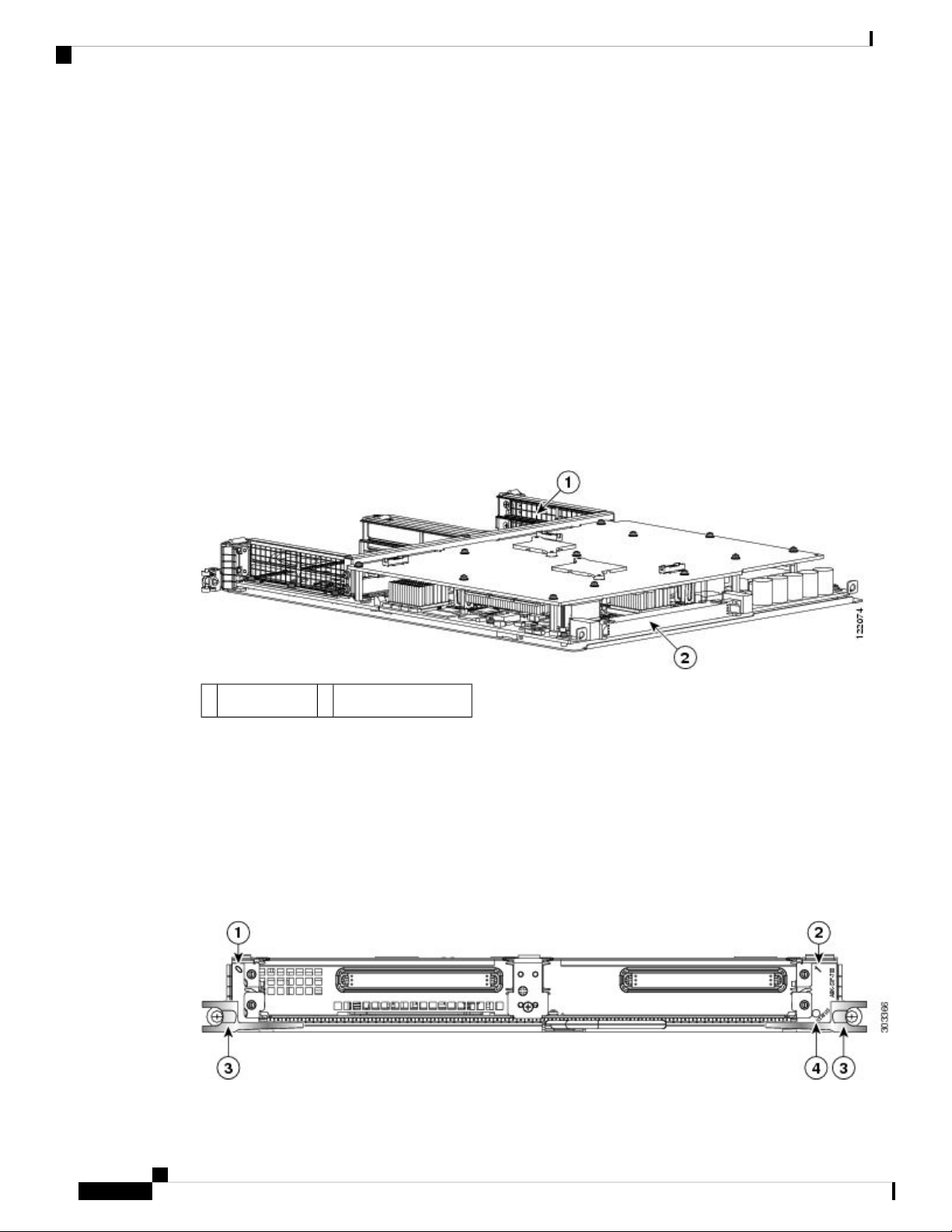
The main Cisco ASR 9000 SIP-700 board components are shown in the figure below.
Figure 1: Cisco ASR 9000 SIP-700 Board—Rear View
Overview: Cisco ASR 9000 Series Router SPA Interface Processors
Backplane connector2SPA enclosure1
Cisco ASR 9000 SIP-700 LED
The Cisco ASR 9000 SIP-700 supports a maximum of 2 single-width, double-height SPAs, 4 single-width,
single-height SPAs, 2 double-width, single-height SPAs, or 1 double-width, double-height SPA. Combinations
are also supported, for example 2 single-width, single-height SPAs and 1 double-width, single-height SPA.
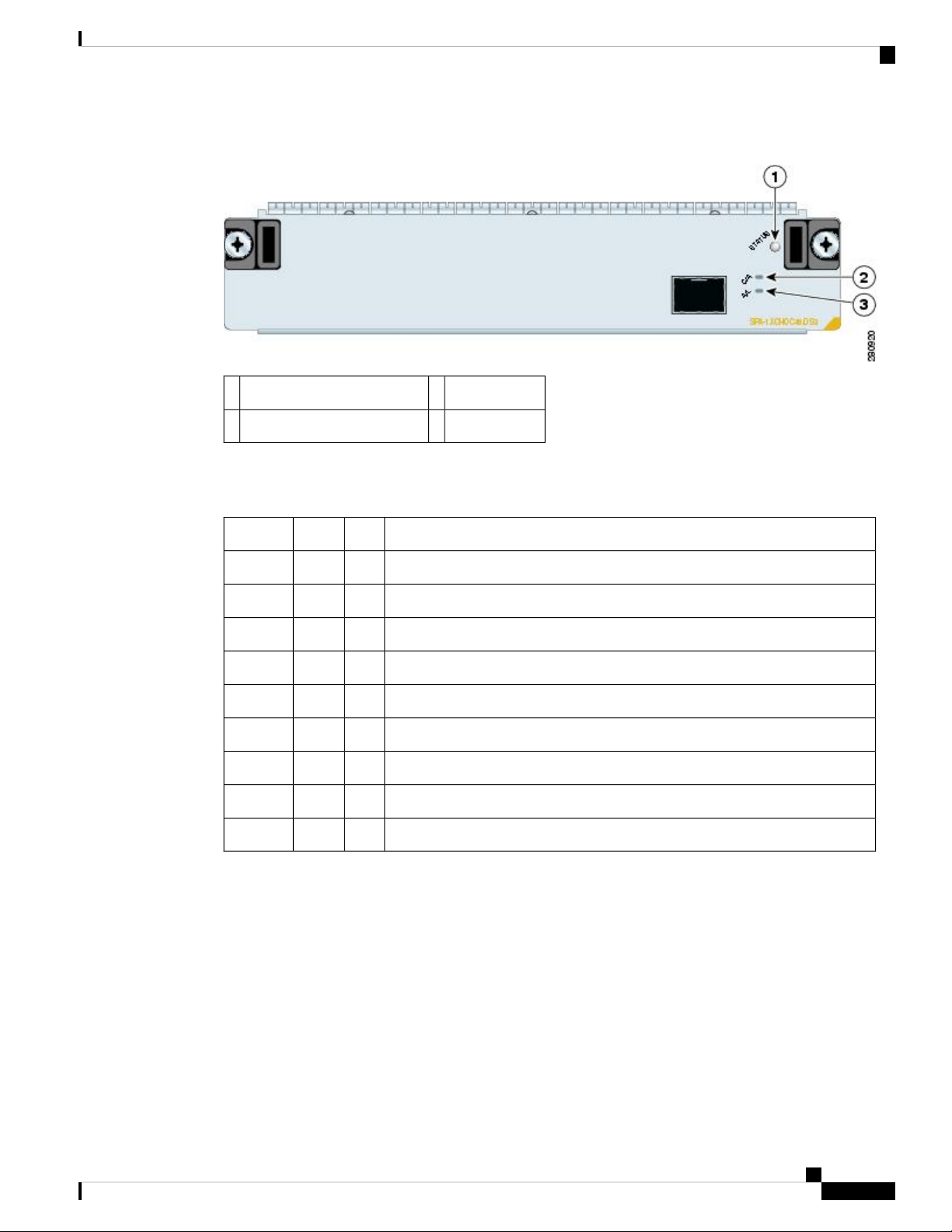
The Cisco ASR 9000 SIP-700 faceplate has one Status LED. The following figure shows the Cisco ASR 9000
SIP-700 faceplate with 2 double-width, single-height SPAs.
Figure 2: Cisco ASR 9000 SIP-700 Faceplate
Cisco ASR 9000 Series Aggregation Services Router SIP and SPA Hardware Installation Guide
4
Page 19

Overview: Cisco ASR 9000 Series Router SPA Interface Processors
Ejector Levers3SPA subslot 01
Status LED for SPA in subslot 14SPA subslot 12
The Cisco ASR 9000 SIP-700 LED is described in the following table.
Table 5: Cisco ASR 9000 SIP-700 LED
MeaningStateColorLED Label
SIP is powered and IOS-XR is loading.OnAmberStatus
SIP is active.OnGreen
SIP is not installed correctly or is not powered.OffN/A
Cisco ASR 9000 SIP-700 Physical Specifications
The Cisco ASR 9000 SIP-700 physical specifications are shown in the following table.
Cisco ASR 9000 SIP-700 Physical Specifications
Table 6: Cisco ASR 9000 SIP-700 Physical Specifications
SpecificationsDescription
Occupies one line card slot on a Cisco ASR 9000 Series Aggregation Services RouterPhysical dimensions
10kg (22 lbs)Shipping weight
32 to 104°F (0 to 40°C)Operating temperature
10 to 90 percent, noncondensingRelative humidity
–4 to 149°F (–20 to 65°C)Storage temperature
SPA Subslot Numbering on the Cisco ASR 9000 SIP-700
The Cisco ASR 9000 SIP-700 supports up to 2 single-width, double-height SPAs, up to 4 single-width,
single-height SPAs, or up to 2 double-width, single-height SPAs. The Cisco ASR 9000 SIP-700 does not
support double-width, double-height SPAs.Note that while the OC192 POS SPA is single-width, single-height,
it is “logically” double-width in that it cannot run with another SPA in the adjacent bay, unless the other SPA
is shut down.
Bay 2 (Top Left)
Bay 0 (Top Right)
Bay 3 (Bottom Left)
Bay 1 (Bottom Right)
The following figure shows a Cisco ASR 9000 SIP-700 with 2 SPAs installed. The left SPA slot is subslot 0
and the right SPA slot is subslot 1.
Cisco ASR 9000 Series Aggregation Services Router SIP and SPA Hardware Installation Guide
5
Page 20
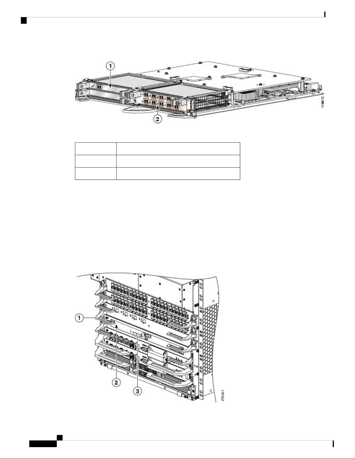
SPA Interface Addresses on the Cisco ASR 9000 SIP-700
Figure 3: Subslot Locations for the 2-Port Channelized OC-12/DS0 SPA
Table 7: Subslot Locations for the 2-Port Channelized OC-12/DS0 SPA
DescriptionCall Out Number
Single height single width SPA in Subslot 1, Bay 01
Double height single width SPA in Subslot 0, Bay 32
Overview: Cisco ASR 9000 Series Router SPA Interface Processors
SPA Interface Addresses on the Cisco ASR 9000 SIP-700
A Cisco ASR 9000 Series Aggregation Services Router identifies a SPA interface address by its rack number,
SIP slot number, SPA subslot, and port number on the SPA, in the format rack/slot/subslot/port . Subslots
and ports are numbered starting from 0, so each Cisco ASR 9000 SIP-700 has two subslots 0 (left) and 1
(right). For example, the interface addresses of a 2-port SPA located in the second SIP subslot, where the SIP
is inserted into router line card slot 3 in rack 0 are 0/3/1/0 and 0/3/1/1. The following figure shows the slot,
subslot, and port locations for the 2-Port Channelized OC-12/DS0 SPA on a Cisco ASR 9006 6-slot chassis.
Figure 4: Slot, Subslot, and Port Locations for the 2-Port Channelized OC-12/DS0 SPA on a Cisco ASR 9006 Chassis
Cisco ASR 9000 Series Aggregation Services Router SIP and SPA Hardware Installation Guide
6
Page 21

Overview: Cisco ASR 9000 Series Router SPA Interface Processors
Table 8: Slot and Port Locations for the 2-Port Channelized OC-12/DS0 SPA
DescriptionCall Out Number
Slot 01
SPA in Subslot 02
Ports 0/0/0/0 and 0/0/0/13
The following figure shows the slot, subslot, and port locations for the 2-Port Channelized OC-12/DS0 SPA
on a Cisco ASR 9010 10-slot chassis.
Figure 5: Slot, Subslot, and Port Locations for the 2-Port Channelized OC-12/DS0 SPA on a Cisco ASR 9010 Chassis
SPA Interface Addresses on the Cisco ASR 9000 SIP-700
Table 9: Slot and Port Locations for the 2-Port Channelized OC-12/DS0 SPA in Slot 3
DescriptionCall Out Number
Slot 31
Subslot 0, Port 3/1/0/0 to 3/1/0/12
Ports of RSP1 in Slot 53
Cisco ASR 9000 Series Aggregation Services Router SIP and SPA Hardware Installation Guide
7
Page 22

SPA Interface Addresses on the Cisco ASR 9000 SIP-700
Overview: Cisco ASR 9000 Series Router SPA Interface Processors
Cisco ASR 9000 Series Aggregation Services Router SIP and SPA Hardware Installation Guide
8
Page 23

CHAPTER 2
Overview: Cisco ASR 9000 Series Router Shared Port Adapters
This chapter describes the shared port adapters (SPAs) that are supported on the Cisco ASR 9000 Series
Aggregation Services Router and contains the following sections:
• SPA Summary, on page 9
• 2-Port Channelized OC-12/DS0 SPA Overview, on page 12
• 1-Port Channelized STM-16/OC-48 SPA Overview, on page 14
• 1-Port OC-48 POS RPR SPA Overview, on page 17
• 2-Port OC-48 POS RPR SPA Overview, on page 19
• 8-Port OC-12 STM-4 POS SPA Overview, on page 22
• 1-Port OC-192 STM-64 POS RPR XFP SPA Overview, on page 25
• 2-Port and 4-Port Clear Channel T3/E3 SPA Overview, on page 29
• 4-Port Channelized T3 to DS0 Overview, on page 31
• 8-Port Channelized T1/E1 SPA Overview, on page 33
• 1-Port Channelized STM-1/OC-3 SPA Overview, on page 35
• 4-Port OC-3/STM-1 POS SPA Overview, on page 38
• 8-Port OC-3/STM-1 POS SPA Overview, on page 41
• 1-Port Channelized OC-3 ATM CEoP SPA Overview, on page 44
• 1-Port and 3-Port Clear Channel OC-3 ATM SPA Overview, on page 46
• 1-Port Clear Channel OC-12 ATM SPA Overview, on page 48
• 2-Port OC-3 STM-1/OC-12 STM-4 POS SPA Overview, on page 50
• 4-Port OC-3 STM-1/OC-12 STM-4 POS SPA Overview, on page 53
• 4-Port OC-48/STM-16 POS/RPR SPA Overview, on page 56
• 2-Port Channelized T3/E3 ATM CEoP SPA Overview , on page 59
• 24-Port Channelized T1/E1/J1 CEoP SPA Overview , on page 61
• 4-Port Serial Interface SPA Overview, on page 66
SPA Summary
The following table shows the summary descriptions of the SPAs that are supported on the Cisco ASR 9000
Series Aggregation Services Router.
Cisco ASR 9000 Series Aggregation Services Router SIP and SPA Hardware Installation Guide
9
Page 24

SPA Summary
Table 10: Supported SPAs on Cisco ASR 9000 Series Aggregation Services Routers
Overview: Cisco ASR 9000 Series Router Shared Port Adapters
SPA-2XCHOC12/DS0
SPA-1XCHOC48/DS3
SPA-2XOC48POS/RPR
SPA-8XOC12-POS
SPA-OC192POS-XFP
SPA-2XT3E3
SPA-4XT3E3
DescriptionProduct Number
double-height
SPA
double-height
double-height
single-height
single-height
SPA
single-height
Number and Type of
Ports
Minimum Cisco
IOS XR Release
Minimum
Hardware
Revision
1.03.9.02 OC122-Port Channelized OC-12/DS0 SPA
1.04.0.01 OC481-Port Channelized OC48/STM16 DS3
1.04.0.02 OC482-Port OC-48/STM16 SPA
1.04.0.08 OC128-Port OC12/STM4 SPA
1.04.0.01 OC1921-Port OC-192/STM-64 POS/RPR SPA
1.04.0.12 or 4 T3/E32-Port and 4-Port Clear Channel T3/E3
SPA-4XCT3/DS0
SPA-8XCHT1/E1
SPA-1XCHSTM1/OC3
SPA-4XOC3-POS-V2
SPA-8XOC3-POS
SPA-1CHOC3-CE-ATM
SPA-1XOC3-ATM-V2
SPA-3XOC3-ATM-V2
1.04.1.04 T34-Port Channelized T3 to DS0
single-height
1.04.1.08 T1/E18-Port Channelized T1/E1 SPA
single-height
1.04.0.11 OC31-Port Channelized OC-3/STM-1 SPA
single-height
1.04.0.14 OC34-Port OC-3/STM-1 POS SPA
single-height
1.04.0.18 OC38-Port OC-3/STM-1 POS SPA
single-height
1.04.2.01 OC31-Port Channelized OC-3 ATM CEoP
SPA
single-height
1.04.2.01 or 3 OC31-Port and 3-Port Clear Channel OC-3
ATM SPA
single-height
Cisco ASR 9000 Series Aggregation Services Router SIP and SPA Hardware Installation Guide
10
Page 25

Overview: Cisco ASR 9000 Series Router Shared Port Adapters
Checking Hardware and Software Compatibility
SPA-1XOC12-ATM-V2
SPA-2XOC12-POS
SPA-4XOC12-POS
SPA-4XOC48POS/RPR
SPA-2CHT3-CE-ATM
SPA-24CHT1-CE-ATM
DescriptionProduct Number
single-height
SPA
single-height
SPA
single-height
double-height
SPA
single-height
Number and Type of
Ports
Minimum Cisco
IOS XR Release
Minimum
Hardware
Revision
1.04.2.01 OC121-Port Clear Channel OC-12 ATM SPA
1.04.3.02 OC122-Port OC-3 STM-1/OC-12 STM-4 POS
1.04.3.04 OC124-Port OC-3 STM-1/OC-12 STM-4 POS
1.04.3.04 OC484-Port OC-48/STM-16 POS/RPR SPA
1.04.3.02 T3/E32-Port Channelized T3/E3 ATM CEoP
1.04.3.024 T1/E124-Port Channelized T1/E1/J1 CEoP SPA
single-height
SPA-8XCHT1/E1-V2
single-height
SPA-1XOC48POS/RPR
single-height
SPA-4XT-Serial
4-Port Serial SPA
single-height
Note
The minimum FPD version for the SPA-4XT-Serial SPA is 1.04. Refer to the "Upgrading FPD" chapter in the System
Management Configuration Guide for Cisco ASR 9000 Series Routers for information on how to verify image versions
and how to perform an upgrade for SPA FPD images.
Checking Hardware and Software Compatibility
To check the minimum software requirements of Cisco IOS XR software with the hardware installed on your
router, Cisco maintains the Software Advisor tool on Cisco.com. This tool does not verify whether SIPs or
SPAs within a system are compatible, but it does provide the minimum Cisco IOS XR requirements for
individual hardware modules or components.
1.05.1.18 T1/E18-Port Channelized T1/E1 SPA
1.05.1.11 OC481-Port OC-48/STM16 SPA
2.06.3.1
2.06.4.14 serial
Cisco ASR 9000 Series Aggregation Services Router SIP and SPA Hardware Installation Guide
11
Page 26
Overview: Cisco ASR 9000 Series Router Shared Port Adapters
2-Port Channelized OC-12/DS0 SPA Overview
Note
Access to this tool is limited to users with Cisco.com login accounts.
To access Software Advisor, click Login at Cisco.com, type Software Advisor in the SEARCH box, and
click GO. Click the link for the Software Advisor tool.
Choose a product family or enter a specific product number to search for the minimum supported software
release needed for your hardware.
2-Port Channelized OC-12/DS0 SPA Overview
The 2-Port Channelized OC-12/DS0 SPA is a double-height SPA that provides Synchronous Optical NETwork
(SONET) network connectivity with a bandwidth of 622.08 Mbps.
The following sections describe the 2-Port Channelized OC-12/DS0 SPA:
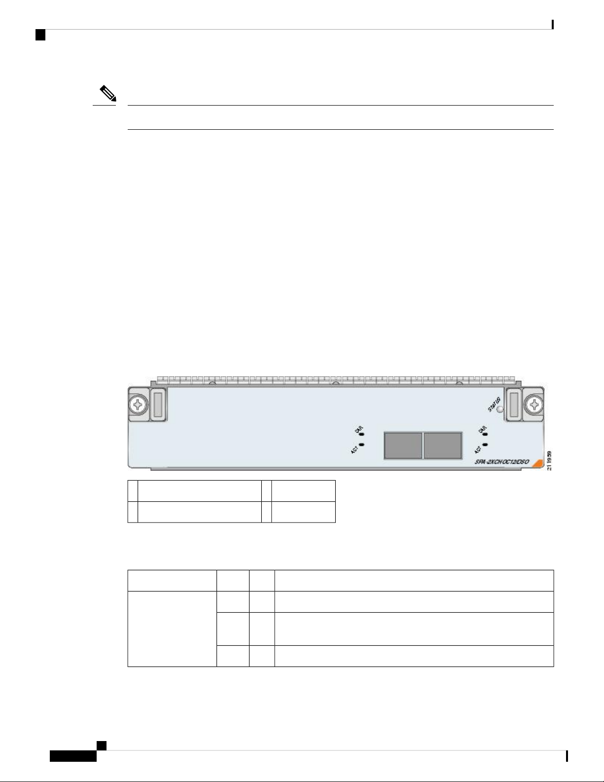
2-Port Channelized OC-12/DS0 SPA LEDs
The 2-Port Channelized OC-12/DS0 SPA has three types of LEDs. There are two LEDs for each port on the
SPA, and one STATUS LED. The following figure shows an example of these LEDs on a SPA.
Figure 6: 2-Port Channelized OC-12/DS0 SPA Faceplate
STATUS LED3CAR (Carrier/Alarm) LED1
ACT (Active Loopback) LED2
The following table describes the 2-Port Channelized OC-12/DS0 SPA LEDs.
Table 11: 2-Port Channelized OC-12/DS0 SPA LEDs
MeaningStateColorLED Label
Port is not enabled by software.OffOffCAR
CAR and ACT LEDs
are per port.
Cisco ASR 9000 Series Aggregation Services Router SIP and SPA Hardware Installation Guide
12
Port is enabled by software, and there is a valid SONET signal without
OnGreen
any alarms.
Port is enabled by software, and there is at least one alarm.OnAmber
Page 27

Overview: Cisco ASR 9000 Series Router Shared Port Adapters
MeaningStateColorLED Label
Port is not enabled by software.
OffOffACT
Port is enabled by software, loopback is off.OnGreen
Port is enabled by software, loopback is on.OnAmber
SPA power is off.
OffOffSTATUS
2-Port Channelized OC-12/DS0 SPA Interface Specifications
STATUS LED is per
SPA.
SPA is ready and operational.OnGreen
SPA power is on and SPA is being configured.OnAmber
2-Port Channelized OC-12/DS0 SPA Interface Specifications
The framer processes incoming and outgoing SONET frames. The framer operates at OC-12c/STM-4 line
rates (622.08 Mbps). Packet data is transported with a user-configured encapsulation (such as Point-to-Point
Protocol [PPP]) and mapped into the STS-12c/STM-4 frame. The main operational mode of the framer is
OC-12, where each one of the 12 Paths can carry a DS3 and each DS3 can carry 28 DS1s.
The 2-Port Channelized OC-12/DS0 SPA interface is compliant with ANSI and Telco standards.
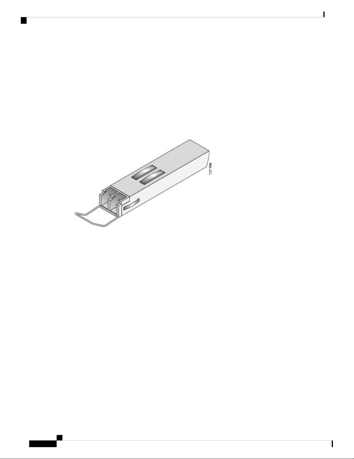
2-Port Channelized OC-12/DS0 SPA SFP Optical Transceiver Modules and Cables
The 2-Port Channelized OC-12/DS0 SPA uses a small form-factor pluggable (SFP) optical transceiver module
installed in each port for SONET single-mode and multimode optical fiber connection. (See the following
figure.)
Cisco Systems qualifies the optics that are approved for use with its SPAs. The 2-Port Channelized OC-12/DS0
SPA supports the following types of optical transceiver modules:
• Multimode (MM) SFP module—SFP-OC12-MM
• Short reach (SR) SFP module—SFP-OC12-SR
• Intermediate reach (IR) SFP module (15 km)—SFP-OC12-IR1
• Long reach (LR) SFP module (40 km)—SFP-OC12-LR1
• LR SFP module (80 km)—SFP-OC12-LR2
Cisco ASR 9000 Series Aggregation Services Router SIP and SPA Hardware Installation Guide
13
Page 28
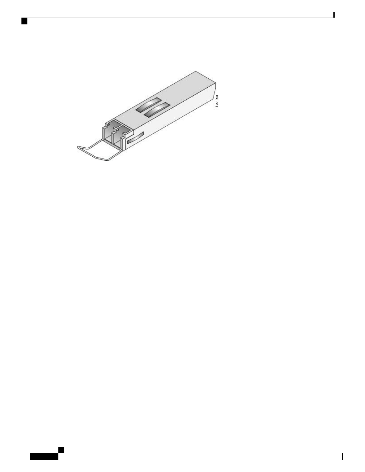
1-Port Channelized STM-16/OC-48 SPA Overview
Figure 7: SFP Optics Module
The SFP optical transceiver modules used with the SPAs provide the following optical fiber options:
• Multimode—622.08-Mbps, OC-12 optical fiber (SONET STS-12c)
Overview: Cisco ASR 9000 Series Router Shared Port Adapters
Use a multimode optical fiber that has a core/cladding diameter of 62.5/125 microns.
• Single-mode—622.08-Mbps, OC-12 optical fiber (SONET STS-12c)
Use a single-mode optical fiber that has a modal-field diameter of 8.7 ±0.5 microns. (Nominal diameter is
approximately 10/125 microns.)
Use single-mode (for intermediate or long-reach configurations) or multimode optical fiber cable to connect
your router to a network or to connect two 2-Port Channelized OC-12/DS0 SPA -equipped routers back to
back.
Long-range SFP optical transceiver modules (for long-reach configurations) cannot be connected back-to-back
without using an attenuator between the two of them.
1-Port Channelized STM-16/OC-48 SPA Overview
The following sections describe the 1-Port Channelized STM-16/OC-48 SPA:
1-Port Channelized STM-16/OC-48 SPA LEDs
The 1-Port Channelized STM-16/OC-48 SPA has two types of LEDs: an A/L LED for the port and a STATUS
LED, as shown in the following figure.
Cisco ASR 9000 Series Aggregation Services Router SIP and SPA Hardware Installation Guide
14
Page 29
Overview: Cisco ASR 9000 Series Router Shared Port Adapters
Figure 8: 1-Port Channelized STM-16/OC-48 SPA Faceplate
A/L (Active Loopback) LED2
The 1-Port Channelized STM-16/OC-48 SPALEDs are described in the following table.
1-Port Channelized STM-16/OC-48 SPA Interface Specifications
STATUS LED3C/A (Carrier/Alarm) LED1
Table 12: 1-Port Channelized STM-16/OC-48 SPA LEDs
MeaningStateColorLED Label
Port is not enabled by software.OffOffC/A
Port is enabled by software, and there is a valid T3 signal without any alarms.OnGreen
Port is enabled by software, and there is at least one alarm.OnAmber
Port is not enabled by software.OffOffA/L
Port is enabled by software, loopback is off.OnGreen
Port is enabled by software, loopback is on.OnAmber
SPA power is off.OffOffSTATUS
SPA is ready and operational.OnGreen
SPA power is on and good, and SPA is being configured.OnAmber
1-Port Channelized STM-16/OC-48 SPA Interface Specifications
The framer processes incoming and outgoing SONET or SDH frames. The framer operates at OC-48/STM-16
line rates (2.488 Gbps).
Packet data is transported with a user-configured encapsulation (such as Point-to-Point Protocol [PPP]) and
is mapped into the STS-48/STM-16 frame. HDLC and Frame-Relay are also supported. The main operational
mode of the framer is OC-48, where each one of the 48 Paths can carry a DS3 and each DS3 can carry 28
DS1s.
Cisco ASR 9000 Series Aggregation Services Router SIP and SPA Hardware Installation Guide
15
Page 30
Overview: Cisco ASR 9000 Series Router Shared Port Adapters
1-Port Channelized STM-16/OC-48 SPA Cables and Connectors
The 1-Port Channelized STM-16/OC-48 SPA interface is compliant with RFC 1619, PPP over SONET/SDH,
and RFC 1662, PPP in HDLC-like Framing. The 1-Port Channelized STM-16/OC-48 SPA also provides
support for SNMP v1 agent (RFC 1155–1157), and Management Information Base (MIB) II (RFC 1213).
1-Port Channelized STM-16/OC-48 SPA Cables and Connectors
The 1-Port Channelized STM-16/OC-48 SPA uses a small form-factor pluggable (SFP) optical transceiver
module installed in the port for SONET and SDH single-mode and multimode optical fiber connection (see
the following figure).
Figure 9: SFP Optics Module
The SFP optical transceiver modules used with the 1-Port Channelized STM-16/OC-48 SPA provide the
following optical fiber options:
• Multimode—2.488-Gbps, OC-48/STM-16 optical fiber (SONET STS-48 or SDH STM-16)
Use a multimode optical fiber that has a core/cladding diameter of 62.5/125 microns.
• Single-mode—2.488-Gbps, OC-48/STM-16 optical fiber (SONET STS-48 or SDH STM-16)
Use a single-mode optical fiber that has a modal-field diameter of 8.7 ±0.5 microns. (Nominal diameter is
approximately 10/125 microns.)
For single-mode and multimode optical fiber connections, you can use either a duplex LC-type cable (see the
figure below) or two simplex LC-type cables, one for transmit (TX) and one for receive (RX).
Use single-mode (for intermediate- or long-reach configurations) or multimode optical fiber cable to connect
your router to a network or to connect two 1-Port Channelized STM-16/OC-48 SPA-equipped routers back
to back.
Long-range SFP optical transceiver modules (for long-reach configurations) cannot be connected back-to-back
without using an attenuator between the two of them.
Cisco ASR 9000 Series Aggregation Services Router SIP and SPA Hardware Installation Guide
16
Page 31

Overview: Cisco ASR 9000 Series Router Shared Port Adapters
Figure 10: LC Type Cable
1-Port OC-48 POS RPR SPA Overview
The following sections describe the 1-Port OC48-POS/RPR SPA:
1-Port OC48-POS/RPR SPA LEDs
The 1-Port OC48-POS/RPR SPA has eight LEDs, as shown in the following figure.
Figure 11: 1-Port OC48-POS/RPR SPA Faceplate
1-Port OC-48 POS RPR SPA Overview
7MATESYNC LED3
4
LED
Note
The WRAP, PASSTHRU, and MATESYNC LEDs apply to the SPA in RPR/SRP mode only.
The 1-Port OC48-POS/RPR SPA LEDs are described in the following table.
Cisco ASR 9000 Series Aggregation Services Router SIP and SPA Hardware Installation Guide
CARRIER LED5WRAP1
ACTIVE LED6PASSTHROUGH LED2
A/L (Active/Loopback)
LED
STATUS LED8CAR (Carrier/Alarm)
17
Page 32

1-Port OC48-POS/RPR SPA LEDs
Table 13: 1-Port OC48-POS/RPR SPA LEDs
Overview: Cisco ASR 9000 Series Router Shared Port Adapters
MeaningStateColorLED Label
Port is not in wrap mode.OffOffWRAP
Port is in wrap mode somewhere on the ring.OnGreen
Port is in wrap mode locally.OnAmber
OffOffPASSTHRU
Port is not in pass-through mode.
Port is in pass-through mode.OnAmber
OffOffMATESYNC
Mate port is not synchronized.
Mate port is synchronized.OnGreen
OffOffC/A
Port is not enabled by software.
Port is enabled by software.OnGreen
OnAmber
Port is enabled by software, and there is at least one
alarm.
OffOffA/L
Port is not enabled by software.
Port is enabled by software, loopback is off.OnGreen
Port is enabled by software, loopback is on.OnAmber
OffOffCARRIER
OnGreen
Port is not enabled by software.
Port is enabled by software, and there is a valid
SONET signal without alarms.
OnAmber
Port is enabled by software, and there is at least one
alarm (LOS, LOF, RDI, and so on).
SRP mode mismatch alarm is indicated.Blinking
OffACTIVE
Port is not enabled by software.Off
Port is enabled by software, and loopback is off.OnGreen
Port is enabled by software, and loopback is on.OnAmber
OffOffSTATUS
SPA power off.
SPA is ready and operational.OnGreen
OnAmber
SPA power is on and good, and the SPA is being
configured.
Cisco ASR 9000 Series Aggregation Services Router SIP and SPA Hardware Installation Guide
18
Page 33

Overview: Cisco ASR 9000 Series Router Shared Port Adapters
1-Port OC48-POS/RPR SPA Interface Specifications
1-Port OC48-POS/RPR SPA Interface Specifications
The physical layer interface for the 1-Port OC48-POS/RPR SPA is Optical Carrier-48 (OC-48), and the 1-Port
OC48-POS/RPR SPA is designed to comply with POS specifications. The 1-Port OC48-POS/RPR SPA
provides one 2.488-Gbps network interface for all supported platforms.
1-Port OC48-POS/RPR SPA Cables, Optical Transceiver Modules, and Connectors
Use single-mode (for intermediate-configurations) optical fiber cable to connect your router to a network or
to connect two OC-48-equipped routers back-to-back.
The 1-Port OC48-POS/RPR SPA supports the following types of optical transceiver modules:
• Single-mode short-reach (SR) SFP module—SFP-OC48-SR
• Single-mode intermediate-reach (IR) SFP module —SFP-OC48-IR1
• Single-mode long-reach (LR) SFP module — SFP-OC48-LR2
The 1-Port OC48-POS/RPR SPA has one duplex LC-type receptacle. For single-mode optical fiber connections,
you can use either a duplex LC-type cable (see the below figure) or two simplex LC-type cables, one for
transmit (TX) and one for receive (RX).
Figure 12: Duplex Patch Cable with LC-Type Connectors
Note
The 40-pin connector on the 1-Port OC-48/STM-16 POS SPA is used for resilient packet ring (RPR)
connections.
2-Port OC-48 POS RPR SPA Overview
The following sections describe the 2-Port OC48-POS/RPR SPA:
2-Port OC48-POS/RPR SPA LEDs
The 2-Port OC48-POS/RPR SPA has five LEDs, as shown in the following figure.
Cisco ASR 9000 Series Aggregation Services Router SIP and SPA Hardware Installation Guide
19
Page 34

2-Port OC48-POS/RPR SPA LEDs
Figure 13: 2-Port OC48-POS/RPR SPA Faceplate
CAR (Carrier/Alarm) LED3
The 2-Port OC48-POS/RPR SPA LEDs are described in the following table.
Table 14: 2-Port OC48-POS/RPR SPA LEDs
Overview: Cisco ASR 9000 Series Router Shared Port Adapters
ACT (Active Loopback) LED4PTH (Pass-Through) LED1
STATUS LED5PRT (Protect) LED2
The PTH and PRT LEDs are not
supported in the ASR9K (since this
SPA doesn't support SR-APS). They
always remain Off, even when the
lamptest is performed.
The PTH and PRT LEDs are not
supported in the ASR9K (since this
SPA doesn't support SR-APS). They
always remain Off, even when the
lamptest is performed.
MeaningStateColorLED Label
Port is not in pass-through mode.OffOffPTH
Port is in pass-through mode.OnAmber
Port is not enabled by software.OffOffCAR
OnGreen
Port is enabled by software, and there is a valid
SONET signal without any alarms.
OnAmber
Port is enabled by software, and there is at least one
alarm.
BlinkingAmber
Port is enabled by software, and there is a side
mismatch.
Port is not in wrap mode or steer.OffOffPRT
A node on the ring is wrapped.OnGreen
A node on the ring is steering pass-throughBlinkingGreen
Cisco ASR 9000 Series Aggregation Services Router SIP and SPA Hardware Installation Guide
20
Page 35

Overview: Cisco ASR 9000 Series Router Shared Port Adapters
2-Port OC48-POS/RPR SPA Interface Specifications
MeaningStateColorLED Label
Port is locally wrappedOnAmber
Port is locally steeringBlinkingAmber
Port is not enabled by software.OffOffACT
Port is enabled by software, loopback is off.OnGreen
Port is enabled by software, loopback is on.OnAmber
SPA power is off.OffOffSTATUS
SPA is ready and operational.OnGreen
OnAmber
SPA power is on and good, and SPA is being
configured.
2-Port OC48-POS/RPR SPA Interface Specifications
The physical layer interface for the 2-Port OC48-POS/RPR SPA is Optical Carrier-48 (OC-48), and the 2-Port
OC48-POS/RPR SPA is designed to comply with POS specifications. The 2-Port OC48-POS/RPR SPA
provides two 2.488-Gbps network interfaces for all supported platforms.
2-Port OC48-POS/RPR SPA Cables, Optical Transceiver Modules, and Connectors
Use single-mode (for intermediate-configurations) optical fiber cable to connect your router to a network or
to connect two OC-48-equipped routers back-to-back.
The 2-Port OC48-POS/RPR SPA supports the following types of optical transceiver modules:
• Single-mode short-reach (SR) SFP module—SFP-OC48-SR
• Single-mode intermediate-reach (IR) SFP module —SFP-OC48-IR1
• Single-mode long-reach (LR) SFP module — SFP-OC48-LR2
Each port on the 2-Port OC48-POS/RPR SPA has one duplex LC-type receptacle. For single-mode optical
fiber connections, you can use either a duplex LC-type cable (see the below figure) or two simplex LC-type
cables, one for transmit (TX) and one for receive (RX).
Figure 14: Duplex Patch Cable with LC-Type Connectors
Cisco ASR 9000 Series Aggregation Services Router SIP and SPA Hardware Installation Guide
21
Page 36

Overview: Cisco ASR 9000 Series Router Shared Port Adapters
8-Port OC-12 STM-4 POS SPA Overview
8-Port OC-12 STM-4 POS SPA Overview
The 8-Port OC12/STM4 SPA is a single-height SPA that installs into one SIP subslot. The SPA with small
form-factor pluggable (SFP) optical transceiver modules provides Optical Carrier Level (OC-n ) for SONET
and Synchronous Transport Module (STM-n ) for SDH network connectivity. On this SPA, any given port
can use an OC-12 SFP module, so the per-port bandwidth can be 622.08 Mbps.
Note
When SFP modules are replaced, the SPA interface retains any previously defined configurations. These
configurations include settings for IP address, clock source, loopback, CRC, and POS flags.
For more information about SPA bandwidth, see the “Bandwidth Oversubscription” topic in this chapter.
For more information about SPAs and their compatibility with SIPs and modular optics, see the “SIP and
SPA Product Overview” chapter in this guide.
The following sections describe the 8-Port OC-3 STM-1/OC-12 STM-4 POS SPA:
8-Port OC12/STM4 SPA LEDs
The 8-Port OC12/STM4 SPA has three types of LEDs: two LEDs for each port on the SPA and one STATUS
LED. The following figure shows the 8-Port OC12/STM4 SPA faceplate.
Figure 15: 8-Port OC12/STM4 SPA Faceplate
A/L (Active/Loopback) LED2
The following table describes the 8-Port OC12/STM4 SPA LEDs.
Table 15: 8-Port OC12/STM4 SPA LEDs
STATUS LED3C/A (Carrier/Alarm) LED1
MeaningStateColorLED Label
SONET controller is shut down.OffOffC/A
Port is enabled by software, and there is a valid SONET signal without any alarms.OnGreen
Port is enabled by software, and there is at least one alarm.OnAmber
Cisco ASR 9000 Series Aggregation Services Router SIP and SPA Hardware Installation Guide
22
Page 37

Overview: Cisco ASR 9000 Series Router Shared Port Adapters
MeaningStateColorLED Label
Interface is shut down.
OffOffA/L
Port is enabled by software, and loopback is off.OnGreen
Port is enabled by software, and loopback is on.OnAmber
SPA power is off.
OffOffSTATUS
SPA is ready and operational.OnGreen
SPA power is on and good, and the SPA is being configured.OnAmber
8-Port OC12/STM4 SPA Interface Specifications
The framer processes incoming and outgoing SONET or SDH frames. The framer operates at OC-12 line
rates (622.08 Mbps). Packet data is transported with a user-configured encapsulation (such as Point-to-Point
Protocol [PPP]) and is mapped into the Layer 2 frame.
8-Port OC12/STM4 SPA Interface Specifications
The 8-Port OC12/STM4 SPA interface complies with the following RFCs:
• RFC 1662, PPP in HDLC-like Framing
• RFC 2427, Multiprotocol Interconnect over Frame Relay
• RFC 2615, PPP over SONET/SDH
8-Port OC12/STM4 SPA Optical Transceiver Modules and Cables
The 8-Port OC12/STM4 SPA uses a small form-factor pluggable (SFP) optical transceiver module installed
in each port for SONET and SDH single-mode and multimode optical fiber connections (see the below figure).
Cisco Systems qualifies the optics that are approved for use with its SPAs. The following OC-12 optical
transceiver modules are supported on the 8-Port OC12/STM4 SPA :
• Multimode (MM) SFP module—SFP-OC12-MM
• Short-reach (SR) SFP module—SFP-OC12-SR
• Intermediate-reach (IR) SFP module (15 km)—SFP-OC12-IR1
• Long-reach (LR) SFP module (40 km)—SFP-OC12-LR1
• Long-reach (LR) SFP module (80 km)—SFP-OC12-LR2
Cisco ASR 9000 Series Aggregation Services Router SIP and SPA Hardware Installation Guide
23
Page 38

OC-12 Module Connections
Figure 16: SFP Optics Module
The following OC-12 optical fiber options are available for the 8-Port OC-12c/STM-4 POS SPA:
Overview: Cisco ASR 9000 Series Router Shared Port Adapters
• Multimode—622.08-Mbps, OC-12 optical fiber (SONET STS-12c or SDH STM-4)
Use a multimode optical fiber that has a core/cladding diameter of 62.5/125 microns.
• Single-mode—622.08-Mbps, OC-12 optical fiber (SONET STS-12c or SDH STM-4)
Use a single-mode optical fiber that has a modal-field diameter of 8.7 ± 0.5 microns. (Nominal diameter is
approximately 10/125 microns.)
For single-mode and multimode optical fiber connections, you can use either a duplex LC-type cable (see the
following figure) or two simplex LC-type cables, one for transmit (TX) and one for receive (RX).
Use single-mode (for short-, intermediate- or long-reach configurations) or multimode optical fiber cable to
connect your router to a network or two OC-12-equipped routers back-to-back.
Long-range SFP optical transceiver modules (for long-reach configurations) cannot be connected back-to-back
without using an attenuator between them.
Figure 17: LC-Type Cable
OC-12 Module Connections
The following table shows the OC-12 specifications of the optics on the 8-Port OC-12c/STM-4 POS SPA.
Cisco ASR 9000 Series Aggregation Services Router SIP and SPA Hardware Installation Guide
24
Page 39

Overview: Cisco ASR 9000 Series Router Shared Port Adapters
Table 16: OC-12 Specifications
1-Port OC-192 STM-64 POS RPR XFP SPA Overview
DescriptionSpecification
Wavelength
Cabling distance (maximum)
Operating case temperature
range
TX power
Receiver sensitivity (maximum)
RX overload
Maximum receiver power
damage
OC-12 MM: 1270 nm to 1380 nmOC-12 SR: 1261 nm to 1360 nmOC-12
IR-1: 1293 nm to 1334 nmOC-12 LR-1: 1280 nm to 1335 nmOC-12 LR-2:
1480 nm to 1580 nm
OC-12 MM: 0.5 km (0.3 miles)OC-12 SR: 2 km (1.2 miles)OC-12 IR-1:
15 km (9.3 miles)OC-12 LR-1: 40 km (24.8 miles)OC-12 LR-2: 80 km
(49.7 miles)
OC-12 MM: 23 to 185 degrees F (–5 to 85 degrees C)OC-12 SR: 23 to 185
degrees F (–5 to 85 degrees C)OC-12 IR-1: 23 to 185 degrees F (–5 to 85
degrees C)OC-12 LR-1: 23 to 185 degrees F (–5 to 85 degrees C)OC-12
LR-2: 23 to 185 degrees F (–5 to 85 degrees C)
OC-12 MM: –20 to –14 dBmOC-12 SR: –15 to –8 dBmOC-12 IR-1: –15
to –8 dBmOC-12 LR-1: –3 to 2 dBmOC-12 LR-2: –3 to 2 dBm
OC-12 MM: –26 dBOC-12 SR: –23 dBmOC-12 IR-1: –28 dBmOC-12
LR-1: –28 dBmOC-12 LR-2: –28 dBm
OC-12 MM: –6 dBmOC-12 SR: –8 dBmOC-12 IR-1: –8 dBmOC-12 LR-1:
–8 dBmOC-12 LR-2: –8 dBm
OC-12 MM: +5 dBmOC-12 SR: +5 dBmOC-12 IR-1: +5 dBmOC-12 LR-1:
+5 dBmOC-12 LR-2: +5 dBm
1-Port OC-192 STM-64 POS RPR XFP SPA Overview
The 1-Port OC-192/STM-64 POS/RPR XFP SPA is a single-height SPA that is installed in one SIP subslot.
The 1-Port OC-192/STM-64 POS/RPR XFP SPA provides SONET and SDH network connectivity with a
bandwidth of 9.95 Gbps.
For more information about SPA bandwidth, see the “Bandwidth Oversubscription” section in this chapter.
For more information about SPAs and their compatibility with SIPs and modular optics, see the SIP overview
chapter in this guide.
The 1-Port OC-192/STM-64 POS/RPR XFP SPA uses a 10-Gbps small form-factor pluggable optical receptacle
for the port allowing connection to single-mode optical fiber. For more information on the optical fiber cables
used with this SPA, see the 1-Port OC-192/STM-64 POS/RPR XFP SPA Optical Transceiver Modules,
Connectors, and Cables, on page 27.
The following sections describe the 1-Port OC-192/STM-64 POS/RPR XFP SPA:
1-Port OC-192/STM-64 POS/RPR XFP SPA LEDs
The 1-Port OC-192/STM-64 POS/RPR XFP SPA has six LEDs, as shown in the following figure.
Cisco ASR 9000 Series Aggregation Services Router SIP and SPA Hardware Installation Guide
25
Page 40

1-Port OC-192/STM-64 POS/RPR XFP SPA LEDs
Figure 18: 1-Port OC-192/STM-64 POS/RPR XFP SPA Faceplate
The following table describes the 1-Port OC-192/STM-64 POS/RPR XFP SPA LEDs.
Overview: Cisco ASR 9000 Series Router Shared Port Adapters
CARRIER LED4WRAP LED1
ACTIVE LED5PASSTHRU LED2
STATUS LED6MATESYNC LED3
Table 17: 1-Port OC-192/STM-64 POS/RPR XFP SPA LEDs
MeaningStateColorLED Label
Port is not in wrap mode.OffOffWRAP
Port is in wrap mode somewhere on the ring.OnGreen
Port is in wrap mode locally.OnAmber
OffOffPASSTHRU
Port is not in pass-through mode.
Port is in pass-through mode.OnAmber
OffOffMATESYNC
Mate port is not synchronized.
Mate port is synchronized.OnGreen
OffOffCARRIER
OnGreen
Port is not enabled by software.
Port is enabled by software, and there is a valid SONET signal without
alarms.
OnAmber
Port is enabled by software, and there is at least one alarm (LOS, LOF, RDI,
and so on).
SRP mode mismatch alarm is indicated.Blinking
OffACTIVE
Port is not enabled by software.Off
Port is enabled by software, and loopback is off.OnGreen
Port is enabled by software, and loopback is on.OnAmber
Cisco ASR 9000 Series Aggregation Services Router SIP and SPA Hardware Installation Guide
26
Page 41

Overview: Cisco ASR 9000 Series Router Shared Port Adapters
1-Port OC-192/STM-64 POS/RPR XFP SPA Interface Specifications
MeaningStateColorLED Label
OffOffSTATUS
SPA power off.
SPA is ready and operational.OnGreen
SPA power is on and good, and the SPA is being configured.OnAmber
1-Port OC-192/STM-64 POS/RPR XFP SPA Interface Specifications
The framer processes incoming and outgoing SONET or SDH frames. The framer operates at OC-192c/STM-64
line rates (9.95 Gbps).
Packet data is transported with a user-configured encapsulation (such as Point-to-Point Protocol [PPP]) and
is mapped into the STS-192c/STM-64 frame.
The 1-Port OC-192/STM-64 POS/RPR XFP SPA interface is compliant with the following RFCs:
• RFC 1662, PPP in HDLC-like Framing
• RFC 2615, PPP over SONET/SDH
Note
For Cisco IOS XR Software Release 3.8.0, the 1-Port OC-192c/STM-64 POS/RPR XFP SPA supports the
Dynamic Packet Transport (DPT) feature. The Cisco DPT family of products delivers scalable Internet service,
reliable IP-aware optical transport, and simplified network operations. The Spatial Reuse Protocol (SRP) is
a MAC-layer protocol developed by Cisco and is used in conjunction with Cisco DPT products, which use a
pair of counter-rotating rings in an optimum fashion to provide improved bandwidth utilization over an
equivalent SONET network.
1-Port OC-192/STM-64 POS/RPR XFP SPA Optical Transceiver Modules, Connectors, and Cables
The 1-Port OC-192/STM-64 POS/RPR XFP SPA uses a single-mode, 9.95 Gbps, OC-192c optical fiber
(SONET STS-192c or SDH STM-64) optical transceiver module for SONET and SDH connection to the
network.
The 1-Port OC-192/STM-64 POS/RPR XFP SPA supports the following types of optical transceiver module:
• Single-mode short-reach (SR) XFP module—XFP-10GLR-OC192SR
• Single-mode intermediate-reach (IR) XFP module—XFP-10GER-OC192IR
• Single-mode very-long reach XFP module—XFP-10GZR-OC192LR
Cisco Systems qualifies the optics that are approved for use with its SPAs. The above-listed XFPs are the
only optical transceiver modules qualified for use.
Use a single-mode optical fiber that has a modal-field diameter of 8.7 ±0.5 microns (nominal diameter is
approximately 10/125 microns) to connect your router to a network.
The following figure shows the cable type for use with the XFP optical transceiver module on the 1-Port
OC-192/STM-64 POS/RPR XFP SPA.
Cisco ASR 9000 Series Aggregation Services Router SIP and SPA Hardware Installation Guide
27
Page 42

OC-192 Module Connections
Figure 19: LC-Type Cable for the XFP Optical Transceiver Modules
OC-192 Module Connections
The following table shows the OC-192 specifications for use with the 1-Port OC-192/STM-64 POS/RPR XFP
SPA.
Table 18: OC-192 Specifications
Overview: Cisco ASR 9000 Series Router Shared Port Adapters
DescriptionSpecification
Wavelength
Cabling distance (maximum)
Operating case temperature range
Tx Power
Receiver Sensitivity (maximum)
Mate Interface Cables
The 1-Port OC-192/STM-64 POS/RPR XFP SPA supports two mate interface configurations:
• Mate between two OC-192c SPAs in the same SIP
OC-192 SR-1: 1290 nm to 1330 nmOC-192 IR-2: 1530 nm to 1565
nmOC-192 LR-2: 1530 nm to 1565 nm
OC-192 SR-1: 2 km (1.2 miles) OC-192 IR-2: 40 km (24.8
miles)OC-192 LR-2: 50 miles (80 km)
OC-192 SR-1: 23 to 158 degrees F (–5 to 70 degrees C)OC-192 IR-2:
23 to 158 degrees F (–5 to 70 degrees C)OC-192 LR-2: 23 to 158
degrees F (–5 to 70 degrees C)
OC-192 SR-1: –6 dBm –1 dBmOC-192 IR-2: –1 dBm +2 dBmOC-192
LR-2: 0 to +4 dBm
OC-192 SR-1: –11 dBmOC-192 IR-2: –14 dBmOC-192 LR-2: –24
dBm
OC-192 SR-1: –1 dBmOC-192 IR-2: +2 dBmOC-192 LR-2: –7.0 dBmRX Overload
OC-192 SR-1: +5 dBmOC-192 IR-2: +5 dBmOC-192 LR-2: +5 dBmMaximum Receiver Power Damage
• Mate between two OC-192c SPAs in adjacent SIPs
Two 1-Port OC-192/STM-64 POS/RPR XFP SPAs are connected using a 40–pin connector copper mate
cable. The length of the cables allow only two possible connection scenarios, next slot horizontal and same
slot vertical. This assumes that the chassis is mounted vertically. The following figure shows the mate cables
used to connect the SPAs.
Cisco ASR 9000 Series Aggregation Services Router SIP and SPA Hardware Installation Guide
28
Page 43

Overview: Cisco ASR 9000 Series Router Shared Port Adapters
Figure 20: SPA Mate Cables
2-Port and 4-Port Clear Channel T3/E3 SPA Overview
Short length RPR mate cable for single port RPR
1
SPAs (CBL-RPR-OC192-L)
Note
The RPR mate cable is necessary only when the SPA is to be used in RPR mode. It is not needed in POS
mode. Support for the RPR feature is dependent on the platform software-release feature content. Verify
support for the RPR feature support using SPA datasheets or by contacting your Cisco representative.
2Long length RPR mate cable for single port RPR
SPAs (CAB-RPR-OC192-S)
2-Port and 4-Port Clear Channel T3/E3 SPA Overview
The following sections describe the 2-Port and 4-Port Clear Channel T3/E3 SPA:
2-Port and 4-Port Clear Channel T3/E3 SPA LEDs
The 2-Port and 4-Port Clear Channel T3/E3 SPA has three types of LEDs: two LEDs for each port on the
SPA, and one STATUS LED, as shown in the following figure.
Cisco ASR 9000 Series Aggregation Services Router SIP and SPA Hardware Installation Guide
29
Page 44

2-Port and 4-Port Clear Channel T3/E3 SPA Interface Specifications
Figure 21: 2-Port and 4-Port Clear Channel T3/E3 SPA Faceplate
TX (Transmit) connector3
The following table describes the 2-Port and 4-Port Clear Channel T3/E3 SPA LEDs.
Overview: Cisco ASR 9000 Series Router Shared Port Adapters
RX (Receive) connector4C/A (Carrier/Alarm) LED1
STATUS LED5A/L (Active Loopback) LED2
Table 19: 2-Port and 4-Port Clear Channel T3/E3 SPA LEDs
MeaningStateColorLED Label
Port is not enabled by software.OffOffC/A
Port is enabled by software, and there is a valid E3 or T3 signal without any alarms.OnGreen
Port is enabled by software, and there is at least one alarm.OnAmber
Port is not enabled by software.OffOffA/L
Port is enabled by software, and loopback is off.OnGreen
Port is enabled by software, and loopback is on.OnAmber
SPA power is off.OffOffSTATUS
SPA is ready and operational.OnGreen
SPA power is on and good, and the SPA is being configured.OnAmber
2-Port and 4-Port Clear Channel T3/E3 SPA Interface Specifications
The framer processes incoming and outgoing T3 (cbit, m13/m23, and unframe) and E3 (g751, g832, and
unframe) frames. The framer operates at T3/E3 line rates (44.736 /34.368 Mbps) depending on the mode in
which it is configured.
Packet data is transported with a user-configurable encapsulation (such as Point-to-Point Protocol [PPP] or
High-Level Data Link Control [HDLC]), and is mapped to T3 and E3 frames. The encapsulations add transport
overhead to the packet of data frames before transporting, and are stripped when a packet is transported to
the far end.
Cisco ASR 9000 Series Aggregation Services Router SIP and SPA Hardware Installation Guide
30
Page 45

Overview: Cisco ASR 9000 Series Router Shared Port Adapters
2-Port and 4-Port Clear Channel T3/E3 SPA Cables and Connectors
The T3/E3 SPA interface is compliant with ANSI and Telco standards. The interface also provides support
for Management Information Base (MIB) RFC 2496 and T1.231.
2-Port and 4-Port Clear Channel T3/E3 SPA Cables and Connectors
The interface connectors on the 2-Port and 4-Port Clear Channel T3/E3 SPA are 75-ohm coaxial Siemax
types, with one connector and cable for transmit (TX) and one for receive (RX).
The following cables can be used with the 2-Port and 4-Port Clear Channel T3/E3 SPA. The cables have BNC
connectors on one end and the Siemax connectors on the other. If similar SPAs are connected back-to-back,
both ends of cable will be Siemax.
• CAB-T3E3-RF-BNC-M (T3 or E3 Cable, 1.0/2.3 RF to BNC-Male, 10 feet)
• CAB-T3E3-RF-BNC-F (T3 or E3 Cable, 1.0/2.3 RF to BNC-Female, 10 feet)
• CAB-T3E3-RF-OPEN (T3 or E3 Cable, 1.0/2.3 RF to BNC-Open end, 10 feet)
Note
The Cisco cable part numbers are 72-4124-01 (with male BNC end) and 72-4131-01 (with female BNC end).
The 2-Port and 4-Port Clear Channel T3/E3 SPA Faceplate figure shows the connectors on the 2-Port and
4-Port Clear Channel T3/E3 SPA, and the following table describes the signal descriptions for these connectors.
Table 20: 2-Port and 4-Port Clear Channel T3/E3 SPA Connectors
MeaningConnector Label
TX
RX
Transmitted signals appear on the center contact, and the outer shield is ground for the
75-ohm RG-59 coaxial cable you attach to the TX BNC connector.
Received signals appear on the center contact, and the outer shield is ground for the 75-ohm
RG-59 coaxial cable you attach to the RX BNC connector.
4-Port Channelized T3 to DS0 Overview
The following sections describe the 4-Port Channelized T3 SPA:
4-Port Channelized T3 to DS0 LEDs
The 4-Port Channelized T3 to DS0 has three types of LEDs. There are two LEDs for each port on the SPA,
and one STATUS LED. The following figure shows an example of these LEDs on a 4-Port Channelized T3
to DS0.
Cisco ASR 9000 Series Aggregation Services Router SIP and SPA Hardware Installation Guide
31
Page 46

4-Port Channelized T3 to DS0 Interface Specifications
Figure 22: 4-Port Channelized T3 to DS0 Faceplate
TX (Transmit) connector3
The 4-Port Channelized T3 to DS0 LEDs are described in the following table.
Overview: Cisco ASR 9000 Series Router Shared Port Adapters
RX (Receive) connector4C/A (Carrier/Alarm) LED1
STATUS LED5A/L (Active Loopback) LED2
Table 21: 4-Port Channelized T3 to DS0 LEDs
MeaningStateColorLED Label
Port is not enabled by software.OffOffC/A
Port is enabled by software, and there is a valid T3 signal without any alarms.OnGreen
Port is enabled by software, and there is at least one alarm.OnAmber
Port is not enabled by software.OffOffA/L
Port is enabled by software, loopback is off.OnGreen
Port is enabled by software, loopback is on.OnAmber
SPA power is off.OffOffSTATUS
SPA is ready and operational.OnGreen
SPA power is on and good, and SPA is being configured.OnAmber
4-Port Channelized T3 to DS0 Interface Specifications
The framer processes incoming and outgoing T3 frames (cbit, m13/m23, and unframe). The framer operates
at T3 line rates (44.2 Mbps).
Packet data is transported with a user-configurable encapsulation (such as Point-to-Point Protocol [PPP] or
High-Level Data Link Control [HDLC]), and is mapped to T3 frames. The encapsulations add transport
overhead to the packet of data frames before transporting, and are stripped when a packet is transported to
the far end.
The 4-Port Channelized T3 to DS0 interface is compliant with ANSI and Telco standards. The interface also
provides support for Management Information Base (MIB) RFC 2495, RFC 2496, and T1.231.
Cisco ASR 9000 Series Aggregation Services Router SIP and SPA Hardware Installation Guide
32
Page 47

Overview: Cisco ASR 9000 Series Router Shared Port Adapters
4-Port Channelized T3 to DS0 Cables and Connectors
Note
The 4-Port Channelized T3 to DS0 supports Frame Relay Fragmentation (FRF.12) and Multilink Frame Relay
(MFR) features for Cisco IOS XR Software Release 3.6.0 and later releases.
4-Port Channelized T3 to DS0 Cables and Connectors
The interface connectors on the 4-Port Channelized T3 to DS0 are 75-ohm coaxial Siemax types, with one
connector and cable for transmit (TX) and one for receive (RX).
The following cables can be used with the 4-Port Channelized T3 to DS0. The cables have BNC connectors
on one end and the Siemax connectors on the other. If similar SPAs are connected back-to-back, both ends
of the cable should have Siemax connectors.
• CAB-T3E3-RF-BNC-M (T3 or E3 Cable, 1.0/2.3 RF to BNC-Male, 10 feet)
• CAB-T3E3-RF-BNC-F (T3 or E3 Cable, 1.0/2.3 RF to BNC-Female, 10 feet)
• CAB-T3E3-RF-OPEN (T3 or E3 Cable, 1.0/2.3 RF to BNC-Open end, 10 feet)
Note
The Cisco cable part numbers are 72-4124-01 (with Male BNC end) and 72-4131-01 (with Female BNC end).
The previous figure shows the Siemax connectors on the 4-Port Channelized T3 to DS0, and the following
table provides the signal descriptions for these connectors.
Table 22: 4-Port Channelized T3 to DS0 Connectors
MeaningConnector Label
TX
RX
Transmitted signals appear on the center contact, and the outer shield is ground for the
75-ohm RG-59 coaxial cable you attach to the TX Siemax connector.
Received signals appear on the center contact, and the outer shield is ground for the 75-ohm
RG-59 coaxial cable you attach to the RX Siemax connector.
8-Port Channelized T1/E1 SPA Overview
The following sections describe the 8-Port Channelized T1/E1 SPA:
8-Port Channelized T1/E1 SPA LEDs
The 8-Port Channelized T1/E1 SPA has three types of LEDs. There are two LEDs for each port on the SPA,
and one STATUS LED as shown in the following figure.
Cisco ASR 9000 Series Aggregation Services Router SIP and SPA Hardware Installation Guide
33
Page 48

8-Port Channelized T1/E1 SPA Interface Specifications
Figure 23: 8-Port Channelized T1/E1 SPA Faceplate
A/L (Active Loopback) LED2
The 8-Port Channelized T1/E1 SPA LEDs are described in the following table.
Table 23: 8-Port Channelized T1/E1 SPA LEDs
Overview: Cisco ASR 9000 Series Router Shared Port Adapters
STATUS LED3C/A (Carrier/Alarm) LED1
MeaningStateColorLED Label
Port is not enabled by software.OffOffC/A
Port is enabled by software, and there is a valid T1 or E1 signal without any alarms.OnGreen
Port is enabled by software, and there is at least one alarm.OnAmber
Port is not enabled by software.OffOffA/L
Port is enabled by software, loopback is off.OnGreen
Port is enabled by software, loopback is on.OnAmber
SPA power is off.OffOffSTATUS
SPA power is on and good, and SPA is being configured.OnAmber
SPA is ready and operational.OnGreen
8-Port Channelized T1/E1 SPA Interface Specifications
The E1 interface on the 8-Port Channelized T1/E1 SPA uses RJ-48c receptacles for E1 (120-Ohm) cables
with RJ-45 connectors. You can use all ports simultaneously. Each E1 connection supports interfaces that
meet G.703 standards. The RJ-45 connection does not require an external transceiver. The E1 ports are E1
interfaces that use 120-ohm shielded twisted pair (STP) cables.
34
Caution
Shielded twisted pair (STP) T1/E1 cables must be used to comply with EN55022/CISPR22 Class A emissions
requirements. For revisions 73-8358-05 through 73-8358-08 Shielded Twisted pair (STP) T1/E1 cables must
be used to comply with FCC Class A emissions requirements.
Cisco ASR 9000 Series Aggregation Services Router SIP and SPA Hardware Installation Guide
Page 49

Overview: Cisco ASR 9000 Series Router Shared Port Adapters
8-Port Channelized T1/E1 SPA Cables, Connectors, and Pinouts
8-Port Channelized T1/E1 SPA Cables, Connectors, and Pinouts
The following figure shows an RJ-45 connector.
Note
The terms RJ-45 and RJ-48c are sometimes used interchangeably. The RJ-48c is the jack or receptacle; the
RJ-45 is the connector.
Figure 24: RJ-45 Connector
The following table describes the signals and connector pinouts for RJ-45 cable connectors.
Table 24: RJ-45 Connector Pinouts
DescriptionSignalPin
Receive ring –RX–1
Receive tip +RX+2
No connectionNC3
Transmit ring –TX–4
Transmit tip +TX+5
No connectionNC6
No connectionNC7
No connectionNC8
1-Port Channelized STM-1/OC-3 SPA Overview
The following sections describe the 1-Port Channelized STM-1/OC-3 SPA:
1-Port Channelized STM-1/OC-3 SPA LEDs
The 1-Port Channelized STM-1/OC-3 SPA has two types of LEDs: an A/L LED for the port and a STATUS
LED, as shown in the following figure.
Cisco ASR 9000 Series Aggregation Services Router SIP and SPA Hardware Installation Guide
35
Page 50

1-Port Channelized STM-1/OC-3 SPA Interface Specifications
Figure 25: 1-Port Channelized STM-1/OC-3 SPA Faceplate
A/L (Active Loopback) LED2
The 1-Port Channelized STM-1/OC-3 SPALEDs are described in the following table.
Table 25: 1-Port Channelized STM-1/OC-3 SPA LEDs
Overview: Cisco ASR 9000 Series Router Shared Port Adapters
STATUS LED3C/A (Carrier/Alarm) LED1
MeaningStateColorLED Label
Port is not enabled by software.OffOffC/A
Port is enabled by software, and there is a valid T3 signal without any alarms.OnGreen
Port is enabled by software, and there is at least one alarm.OnAmber
Port is not enabled by software.OffOffA/L
Port is enabled by software, loopback is off.OnGreen
Port is enabled by software, loopback is on.OnAmber
SPA power is off.OffOffSTATUS
SPA is ready and operational.OnGreen
SPA power is on and good, and SPA is being configured.OnAmber
1-Port Channelized STM-1/OC-3 SPA Interface Specifications
The framer processes incoming and outgoing SONET or SDH frames. The framer operates at OC-3/STM-1
line rates (155.52 Mbps).
Packet data is transported with a user-configured encapsulation (such as Point-to-Point Protocol [PPP]) and
is mapped into the STS-3/STM-1 frame.
The 1-Port Channelized STM-1/OC-3 SPA interface is compliant with RFC 1619, PPP over SONET/SDH,
and RFC 1662, PPP in HDLC-like Framing. The 1-Port Channelized STM-1/OC-3 SPA also provides support
for SNMP v1 agent (RFC 1155–1157), and Management Information Base (MIB) II (RFC 1213).
Cisco ASR 9000 Series Aggregation Services Router SIP and SPA Hardware Installation Guide
36
Page 51

Overview: Cisco ASR 9000 Series Router Shared Port Adapters
1-Port Channelized STM-1/OC-3 SPA Cables and Connectors
Note
The 1-Port Channelized STM-1/OC-3 SPA supports Frame Relay Fragmentation (FRF.12) and Multilink
Frame Relay (MFR) features for Cisco IOS XR Software Release 4.0.1 and later releases.
1-Port Channelized STM-1/OC-3 SPA Cables and Connectors
The 1-Port Channelized STM-1/OC-3 SPA uses a small form-factor pluggable (SFP) optical transceiver
module installed in the port for SONET and SDH single-mode and multimode optical fiber connection (see
the below figure).
Figure 26: SFP Optics Module
The SFP optical transceiver modules used with the 1-Port Channelized STM-1/OC-3 SPA provide the following
optical fiber options:
• Multimode—155-Mbps, OC-3/STM-1 optical fiber (SONET STS-3 or SDH STM-1)
Use a multimode optical fiber that has a core/cladding diameter of 62.5/125 microns.
• Single-mode—155-Mbps, OC-3/STM-1 optical fiber (SONET STS-3 or SDH STM-1)
Use a single-mode optical fiber that has a modal-field diameter of 8.7 ±0.5 microns. (Nominal diameter is
approximately 10/125 microns.)
For single-mode and multimode optical fiber connections, you can use either a duplex LC-type cable (see the
below figure) or two simplex LC-type cables, one for transmit (TX) and one for receive (RX).
Use single-mode (for intermediate- or long-reach configurations) or multimode optical fiber cable to connect
your router to a network or to connect two 1-Port Channelized STM-1/OC-3 SPA-equipped routers back to
back.
Long-range SFP optical transceiver modules (for long-reach configurations) cannot be connected back-to-back
without using an attenuator between the two of them.
Cisco ASR 9000 Series Aggregation Services Router SIP and SPA Hardware Installation Guide
37
Page 52

4-Port OC-3/STM-1 POS SPA Overview
Figure 27: LC Type Cable
The 1-Port Channelized STM-1/OC-3 SPA is a single-height SPA that installs into one SIP subslot. The 1-Port
Channelized STM-1/OC-3 SPA with small form-factor pluggable (SFP) optical transceiver modules supports
SONET and SDH protocols with a per-port bandwidth of 155.52 Mbps. The 1-Port Channelized STM-1/OC-3
SPA operates at quarter rate.
Note
When SFP modules are replaced, the SPA interface retains any previously defined configurations. These
configurations include settings for IP address, clock source, loopback, Cyclic Redundancy Check (CRC), and
POS flags.
Overview: Cisco ASR 9000 Series Router Shared Port Adapters
For more information about SPA bandwidth, see the “Bandwidth Oversubscription” section in this chapter.
For more information about SPAs and their compatibility with SIPs and modular optics, see the “SIP and
SPA Product Overview” chapter in this guide.
4-Port OC-3/STM-1 POS SPA Overview
The following sections describe the 4-Port OC-3/STM-1 POS SPA:
4-Port OC-3/STM-1 POS SPA LEDs
The 4-Port OC-3/STM-1 POS SPA has three types of LEDs: two LEDs for each port on the SPA and one
STATUS LED. The following figure shows the 4-Port OC-3/STM-1 POS SPA.
Figure 28: 4-Port OC-3/STM-1 POS SPA Faceplate
STATUS LED3C/A (Carrier/Alarm) LED1
A/L (Active/Loopback) LED2
The following table describes the 4-Port OC-3/STM-1 POS SPA LEDs.
Cisco ASR 9000 Series Aggregation Services Router SIP and SPA Hardware Installation Guide
38
Page 53

Overview: Cisco ASR 9000 Series Router Shared Port Adapters
Table 26: 4-Port OC-3/STM-1 POS SPA LEDs
MeaningStateColorLED Label
SONET controller is shut down.OffOffC/A
Port is enabled by software, and there is a valid SONET signal without any alarms.OnGreen
Port is enabled by software, and there is at least one alarm.OnAmber
Interface is shut down.
OffOffA/L
Port is enabled by software, and loopback is off.OnGreen
Port is enabled by software, and loopback is on.OnAmber
SPA power is off.
OffOffSTATUS
SPA is ready and operational.OnGreen
SPA power is on and good, and the SPA is being configured.OnAmber
4-Port OC-3/STM-1 POS SPA Interface Specifications
4-Port OC-3/STM-1 POS SPA Interface Specifications
The framer processes incoming and outgoing SONET or SDH frames. The framer operates at OC-3c/STM-1
line rates (155.52 Mbps).
Packet data is transported with a user-configured encapsulation (such as Point-to-Point Protocol [PPP]) and
is mapped into the STS-3c/STM-1 frame.
The 4-Port OC-3/STM-1 POS SPA interface complies with the following RFCs:
• RFC 1662, PPP in HDLC-like Framing
• RFC 2427, Multiprotocol Interconnect over Frame Relay
• RFC 2615, PPP over SONET/SDH
4-Port OC-3/STM-1 POS SPA Optical Transceiver Modules and Cables
The 4-Port OC-3/STM-1 POS SPA uses a small form-factor pluggable (SFP) optical transceiver module
installed in each port for SONET and SDH single-mode and multimode optical fiber connection (see the below
figure).
Cisco Systems qualifies the optics that are approved for use with its SPAs. The 4-Port OC-3/STM-1 POS
SPA supports the following types of optical transceiver modules:
• Multimode (MM) SFP module—SFP-OC3-MM
• Short-reach (SR) SFP module—SFP-OC3-SR
• Intermediate-reach (IR) SFP module (15 km)—SFP-OC3-IR1
• Long-reach (LR) SFP module (40 km)—SFP-OC3-LR1
• Long-reach (LR) SFP module (80 km)—SFP-OC3-LR2
Cisco ASR 9000 Series Aggregation Services Router SIP and SPA Hardware Installation Guide
39
Page 54

OC-3 Module Connections
Figure 29: SFP Optics Module
The SFP optical transceiver modules used with the 4-Port OC-3/STM-1 POS SPA provide the following
optical fiber options:
Use a multimode optical fiber that has a core/cladding diameter of 62.5/125 microns.
Overview: Cisco ASR 9000 Series Router Shared Port Adapters
• Multimode—155-Mbps, OC-3c/STM-1 optical fiber (SONET STS-3c or SDH STM-1)
• Single-mode—155-Mbps, OC-3c/STM-1 optical fiber (SONET STS-3c or SDH STM-1)
Use a single-mode optical fiber that has a modal-field diameter of 8.7 ± 0.5 microns. (Nominal diameter is
approximately 10/125 microns.)
For single-mode and multimode optical fiber connections, you can use either a duplex LC-type cable (see the
below figure) or two simplex LC-type cables, one for transmit (TX) and one for receive (RX).
Use single-mode (for intermediate-reach or long-reach configurations) or multimode optical fiber cable to
connect your router to a network or to connect two 4-Port OC-3/STM-1 POS SPA-equipped routers
back-to-back.
Long-range SFP optical transceiver modules (for long-reach configurations) cannot be connected back-to-back
without using an attenuator between them.
Figure 30: LC-Type Cable
OC-3 Module Connections
The following table shows the OC-3 specifications of the optics on the 4-Port OC-3/STM-1 POS SPA.
Table 27: OC-3 Specifications
DescriptionSpecification
Wavelength
OC-3 MM: 1270 nm to 1380 nmOC-3 SR: 1260 nm to 1360 nmOC-3 IR-1:
1261 nm to 1360 nmOC-3 LR-1: 1263 nm to1360 nmOC-3 LR-2: 1480
nm to 1580 nm
Cisco ASR 9000 Series Aggregation Services Router SIP and SPA Hardware Installation Guide
40
Page 55

Overview: Cisco ASR 9000 Series Router Shared Port Adapters
8-Port OC-3/STM-1 POS SPA Overview
DescriptionSpecification
Cabling distance (maximum)
Operating case temperature
range
TX power
Receiver sensitivity (maximum)
RX overload
Maximum receiver power
damage
OC-3 MM: 2 km (1.2 miles)OC-3 SR: 2 km (1.2 miles)OC-3 IR-1: 15 km
(9.3 miles)OC-3 LR-1: 40 km (24.8 miles)OC-3 LR-2: 80 km (49.7 miles)
OC-3 MM: 23 to 185 degrees F (–5 to 85 degrees C)OC-3 SR: 23 to 185
degrees F (–5 to 85 degrees C)OC-3 IR-1: 23 to 185 degrees F (–5 to 85
degrees C)OC-3 LR-1: 23 to 185 degrees F (–5 to 85 degrees C)OC-3 LR-2:
23 to 185 degrees F (–5 to 85 degrees C)
OC-3 MM: –19 to –14 dBmOC-3 SR: –15 to –8 dBmOC-3 IR-1: –15 to
–8 dBmOC-3 LR-1: –5 to 0 dBmOC-3 LR-2: –5 to 0 dBm
OC-3 MM: –30 dBmOC-3 SR: –23 dBmOC-3 IR-1: –28 dBmOC-3 LR-1:
–34 dBmOC-3 LR-2: –34 dBm
OC-3 MM: –5 dBmOC-3 SR: –8 dBmOC-3 IR-1: –8 dBmOC-3 LR-1: –10
dBmOC-3 LR-2: –10 dBm
OC-3 MM: +5 dBmOC-3 SR: +5 dBmOC-3 IR-1: +5 dBmOC-3 LR-1: +5
dBmOC-3 LR-2: +5 dBm
8-Port OC-3/STM-1 POS SPA Overview
The 8-Port OC-3/STM-1 POS SPA is a single-height SPA that installs into one SIP subslot. The SPA with
small form-factor pluggable (SFP) optical transceiver modules provides Optical Carrier Level (OC-n ) for
SONET and Synchronous Transport Module (STM-n ) for SDH network connectivity. On this SPA, any given
port can use an OC-3 SFP module, so the per-port bandwidth can be 155.52 Mbps.
Note
When SFP modules are replaced, the SPA interface retains any previously defined configurations. These
configurations include settings for IP address, clock source, loopback, CRC, and POS flags.
For more information about SPA bandwidth, see the “Bandwidth Oversubscription” topic in this chapter.
For more information about SPAs and their compatibility with SIPs and modular optics, see the “SIP and
SPA Product Overview” chapter in this guide.
The following sections describe the 8-Port OC-3/STM-1 POS SPA:
8-Port OC-3/STM-1 POS SPA LEDs
The 8-Port OC-3/STM-1 POS SPA has three types of LEDs: two LEDs for each port on the SPA and one
STATUS LED. The following figure shows the 8-Port OC-3/STM-1 POS SPA faceplate.
Cisco ASR 9000 Series Aggregation Services Router SIP and SPA Hardware Installation Guide
41
Page 56

8-Port OC-3/STM-1 POS SPA Interface Specifications
Figure 31: 8-Port OC-3/STM-1 POS SPA Faceplate
A/L (Active/Loopback) LED2
The following table describes the 8-Port OC-3/STM-1 POS SPA LEDs.
Table 28: 8-Port OC-3/STM-1 POS SPA LEDs
Overview: Cisco ASR 9000 Series Router Shared Port Adapters
STATUS LED3C/A (Carrier/Alarm) LED1
MeaningStateColorLED Label
SONET controller is shut down.OffOffC/A
Port is enabled by software, and there is a valid SONET signal without any alarms.OnGreen
Port is enabled by software, and there is at least one alarm.OnAmber
Interface is shut down.
OffOffA/L
Port is enabled by software, and loopback is off.OnGreen
Port is enabled by software, and loopback is on.OnAmber
SPA power is off.
OffOffSTATUS
SPA is ready and operational.OnGreen
SPA power is on and good, and the SPA is being configured.OnAmber
8-Port OC-3/STM-1 POS SPA Interface Specifications
The framer processes incoming and outgoing SONET or SDH frames. The framer operates at OC-3 line rates
(155.52 Mbps). Packet data is transported with a user-configured encapsulation (such as Point-to-Point Protocol
[PPP]) and is mapped into the Layer 2 frame.
The 8-Port OC-3/STM-1 POS SPA interface complies with the following RFCs:
• RFC 1662, PPP in HDLC-like Framing
• RFC 2427, Multiprotocol Interconnect over Frame Relay
• RFC 2615, PPP over SONET/SDH
Cisco ASR 9000 Series Aggregation Services Router SIP and SPA Hardware Installation Guide
42
Page 57

Overview: Cisco ASR 9000 Series Router Shared Port Adapters
8-Port OC-3/STM-1 POS SPA Optical Transceiver Modules and Cables
8-Port OC-3/STM-1 POS SPA Optical Transceiver Modules and Cables
The 8-Port OC-3/STM-1 POS SPA uses a small form-factor pluggable (SFP) optical transceiver module
installed in each port for SONET and SDH single-mode and multimode optical fiber connections (see the
following figure).
Cisco Systems qualifies the optics that are approved for use with its SPAs. The following OC-3 optical
transceiver modules are supported on the 8-Port OC-3/STM-1 POS SPA:
• Multimode (MM) SFP module—SFP-OC3-MM
• Short-reach (SR) SFP module—SFP-OC3-SR
• Intermediate-reach (IR) SFP module (15 km)—SFP-OC3-IR1
• Long-reach (LR) SFP module (40 km)—SFP-OC3-LR1
• Long-reach (LR) SFP module (80 km)—SFP-OC3-LR2
Figure 32: SFP Optics Module
The following OC-3 optical fiber options are available for the 8-Port OC-3/STM-1 POS SPA:
• Multimode—155.52-Mbps, OC-3 optical fiber (SONET STS-3c or SDH STM-1)
Use a multimode optical fiber that has a core/cladding diameter of 62.5/125 microns.
• Single-mode—155.52-Mbps, OC-3 optical fiber (SONET STS-3c or SDH STM-1)
Use a single-mode optical fiber that has a modal-field diameter of 8.7 ± 0.5 microns. (Nominal diameter is
approximately 10/125 microns.)
For single-mode and multimode optical fiber connections, you can use either a duplex LC-type cable (see the
below figure) or two simplex LC-type cables, one for transmit (TX) and one for receive (RX).
Use single-mode (for short-, intermediate- or long-reach configurations) or multimode optical fiber cable to
connect your router to a network or two OC-3-equipped or OC-12-equipped routers back-to-back.
Long-range SFP optical transceiver modules (for long-reach configurations) cannot be connected back-to-back
without using an attenuator between them.
Figure 33: LC-Type Cable
Cisco ASR 9000 Series Aggregation Services Router SIP and SPA Hardware Installation Guide
43
Page 58

OC-3 Module Connections
OC-3 Module Connections
The following table shows the OC-3 specifications of the optics on the 8-Port OC-3/STM-1 POS SPA.
Table 29: OC-3 Specifications
Overview: Cisco ASR 9000 Series Router Shared Port Adapters
DescriptionSpecification
Wavelength
Cabling distance (maximum)
Operating case temperature
range
TX power
Receiver sensitivity (maximum)
RX overload
Maximum receiver power
damage
OC-3 MM: 1270 nm to 1380 nmOC-3 SR: 1260 nm to 1360 nmOC-3 IR-1:
1261 nm to 1360 nmOC-3 LR-1: 1263 nm to1360 nmOC-3 LR-2: 1480
nm to 1580 nm
OC-3 MM: 2 km (1.2 miles)OC-3 SR: 2 km (1.2 miles)OC-3 IR-1: 15 km
(9.3 miles)OC-3 LR-1: 40 km (24.8 miles)OC-3 LR-2: 80 km (49.7 miles)
OC-3 MM: 23 to 185 degrees F (–5 to 85 degrees C)OC-3 SR: 23 to 185
degrees F (–5 to 85 degrees C)OC-3 IR-1: 23 to 185 degrees F (–5 to 85
degrees C)OC-3 LR-1: 23 to 185 degrees F (–5 to 85 degrees C)OC-3 LR-2:
23 to 185 degrees F (–5 to 85 degrees C)
OC-3 MM: –19 to –14 dBmOC-3 SR: –15 to –8 dBmOC-3 IR-1: –15 to
–8 dBmOC-3 LR-1: –5 to 0 dBmOC-3 LR-2: –5 to 0 dBm
OC-3 MM: –30 dBmOC-3 SR: –23 dBmOC-3 IR-1: –28 dBmOC-3 LR-1:
–34 dBmOC-3 LR-2: –34 dBm
OC-3 MM: –5 dBmOC-3 SR: –8 dBmOC-3 IR-1: –8 dBmOC-3 LR-1: –10
dBmOC-3 LR-2: –10 dBm
OC-3 MM: +5 dBmOC-3 SR: +5 dBmOC-3 IR-1: +5 dBmOC-3 LR-1: +5
dBmOC-3 LR-2: +5 dBm
1-Port Channelized OC-3 ATM CEoP SPA Overview
The following sections describe the 1-Port Channelized OC-3 ATM CEoP SPA:
• 1-Port Channelized OC-3 ATM CEoP SPA LEDs
• 1-Port Channelized OC-3 ATM CEoP SPA Interface Specifications
• 1-Port Channelized OC-3 ATM CEoP SPA Optical Transceiver Modules and Cables
1-Port Channelized OC-3 ATM CEoP SPA LEDs
The 1-Port Channelized OC-3 ATM CEoP SPA has three types of LEDs. There are two LEDs for the port on
the SPA, and one STATUS LED as shown in the following figure.
Cisco ASR 9000 Series Aggregation Services Router SIP and SPA Hardware Installation Guide
44
Page 59

Overview: Cisco ASR 9000 Series Router Shared Port Adapters
Figure 34: 1-Port Channelized OC-3 ATM CEoP SPA Faceplate
A/L (Active Loopback) LED2
The 1-Port Channelized OC-3 ATM CEoP SPA LEDs are described in the following table.
Table 30: 1-Port Channelized OC-3 ATM CEoP SPA LEDs
MeaningStateColorLED Label
1-Port Channelized OC-3 ATM CEoP SPA Interface Specifications
STATUS LED3C/A (Carrier/Alarm) LED1
Port is not enabled by software.OffOffC/A
Port is enabled by software.OnGreen
Port is enabled by software, and there is at least one alarm.OnAmber
Port is not enabled by software.OffOffA/L
Port is enabled by software, loopback is off.OnGreen
Port is enabled by software, loopback is on.OnAmber
SPA power is off.OffOffSTATUS
SPA power is on and good, and SPA is being configured.OnAmber
SPA is ready and operational.OnGreen
1-Port Channelized OC-3 ATM CEoP SPA Interface Specifications
The physical layer interface for the 1-Port Channelized OC-3 ATM CEoP SPA is Optical Carrier-3 (OC-3).
The 1-Port Channelized OC-3 ATM CEoP SPA provides one 155.52-Mbps OC-3 network interface for all
supported platforms.
The single SPA port accepts an SFP module with a duplex LC-type receptacle that allows connection to optical
fiber.
1-Port Channelized OC-3 ATM CEoP SPA Optical Transceiver Modules and Cables
Cisco Systems qualifies the optics that are approved for use with its SPAs. The 1-Port Channelized OC-3
ATM CEoP SPA supports the following types of optical transceiver modules:
Cisco ASR 9000 Series Aggregation Services Router SIP and SPA Hardware Installation Guide
45
Page 60

Overview: Cisco ASR 9000 Series Router Shared Port Adapters
1-Port and 3-Port Clear Channel OC-3 ATM SPA Overview
• Multimode (MM) SFP module—SFP-OC3-MM
• Short Reach (SR) SFP module—SFP-OC3-SR
• Intermediate Reach (IR) SFP module (15 km)—SFP-OC3-IR1
• Long Reach (LR) SFP module (40 km)—SFP-OC3-LR1
• Long Reach 2 (LR2) SFP module (80 km)—SFP-OC3-LR2
1-Port and 3-Port Clear Channel OC-3 ATM SPA Overview
The 1-Port and 3-Port Clear Channel OC-3 ATM SPA is a single-height SPA that installs into one SIP subslot.
The Clear Channel OC-3 ATM SPA with small form-factor pluggable (SFP) optical transceiver modules
provides SONET and SDH network connectivity with a per-port bandwidth of 155.52 Mbps. For more
information about SPA bandwidth, see the “Bandwidth Oversubscription” section in this chapter.
The following sections describe the 1-Port and 3-Port Clear Channel OC-3 ATM SPA:
1-Port and 3-Port Clear Channel OC-3 ATM SPA LEDs
The 1-Port and 3-Port Clear Channel OC-3 ATM SPA has three types of LEDs. There are two LEDs for each
port on the SPA, and one STATUS LED. The following figure shows an example of these LEDs on a 3-Port
Clear Channel OC-3 ATM SPA.
Figure 35: 3-Port Clear Channel OC-3 ATM SPA Faceplate
STATUS LED3C/A (Carrier/Alarm) LED1
A/L (Active Loopback) LED2
The 1-Port and 3-Port Clear Channel OC-3 ATM SPA LEDs are described in the table below.
Table 31: 1-Port and 3-Port Clear Channel OC-3 ATM SPA LEDs
MeaningStateColorLED Label
Port is not enabled by software.OffOffC/A
Port is enabled by software, and there is a valid SONET signal without any alarms.OnGreen
Port is enabled by software, and there is at least one alarm.OnAmber
Port is not enabled by software.OffOffA/L
Port is enabled by software, and loopback is off.OnGreen
Cisco ASR 9000 Series Aggregation Services Router SIP and SPA Hardware Installation Guide
46
Page 61

Overview: Cisco ASR 9000 Series Router Shared Port Adapters
1-Port and 3-Port Clear Channel OC-3 ATM SPA Interface Specifications
MeaningStateColorLED Label
Port is enabled by software, and loopback is on.OnAmber
SPA power is off.OffOffSTATUS
SPA power is on and good, and SPA is being configured.OnAmber
SPA is ready and operational.OnGreen
1-Port and 3-Port Clear Channel OC-3 ATM SPA Interface Specifications
The physical layer interface for the 1-Port and 3-Port Clear Channel OC-3 ATM SPA is Optical Carrier-3
(OC-3), and the data link layer is designed to comply with ATM specifications. The 1-Port and 3-Port Clear
Channel OC-3 ATM SPA provides up to one and three 155-Mbps OC-3 network interfaces, respectively, for
all supported platforms.
Each SPA port accepts an SFP module with a duplex LC-type receptacle that allows connection to single-mode
or multimode optical fiber.
1-Port and 3-Port Clear Channel OC-3 ATM SPA Cables and Connectors
The 1-Port and 3-Port Clear Channel OC-3 ATM SPA uses a small form-factor pluggable (SFP) optical
transceiver module installed in each port for SONET and SDH single-mode and multimode optical fiber
connection.
Figure 36: SFP Optics Module
The SFP optical transceiver modules used with the 1-Port and 3-Port Clear Channel OC-3 ATM SPA provide
the following optical fiber options:
• Multimode—155-Mbps, OC-3 optical fiber (SONET STS-3c or SDH STM-1)
Use a multimode optical fiber that has a core/cladding diameter of 62.5/125 microns.
• Single-mode—155-Mbps, OC-3 optical fiber (SONET STS-3c or SDH STM-1)
Use a single-mode optical fiber that has a modal-field diameter of 8.7 ± 0.5 microns. (Nominal diameter is
approximately 10/125 microns.)
For single-mode and multimode optical fiber connections, you can use either a duplex LC-type cable or two
simplex LC-type cables, one for transmit (TX) and one for receive (RX).
Cisco ASR 9000 Series Aggregation Services Router SIP and SPA Hardware Installation Guide
47
Page 62

Overview: Cisco ASR 9000 Series Router Shared Port Adapters
1-Port Clear Channel OC-12 ATM SPA Overview
Use a single-mode (for intermediate-reach or long-reach configurations) or multimode optical fiber cable to
connect your router to a network or to connect two OC-3-equipped routers back-to-back.
Long-range SFP optical transceiver modules (for long-reach configurations) cannot be connected back-to-back
without using an attenuator between them.
Figure 37: Duplex Patch Cable with LC-Type Connectors
1-Port Clear Channel OC-12 ATM SPA Overview
The 1-Port Clear Channel OC-12 ATM SPA is a single-height ATM SPA that can be installed into one SIP
subslot. The OC-12 ATM SPA with small form-factor pluggable (SFP) optical transceiver modules provides
SONET and SDH network connectivity with a per-port bandwidth of 622.08 Mbps. For more information
about SPA bandwidth, see the “Bandwidth Oversubscription” section in this chapter.
The following sections describe the 1-Port Clear Channel OC-12 ATM SPA:
1-Port Clear Channel OC-12 ATM SPA LEDs
The 1-Port Clear Channel OC-12 ATM SPA has three types of LEDs. There are two LEDs for the port on the
SPA, and one STATUS LED, as shown in the following figure.
Figure 38: 1-Port Clear Channel OC-12 ATM SPA Faceplate
STATUS LED3C/A (Carrier/Alarm) LED1
A/L (Active Loopback) LED2
The 1-Port Clear Channel OC-12 ATM SPA LEDs are described in the following table.
Table 32: 1-Port Clear Channel OC-12 ATM SPA LEDs
MeaningStateColorLED Label
Port is not enabled by software.OffOffC/A
Port is enabled by software, and there is a valid SONET signal without any alarms.OnGreen
Cisco ASR 9000 Series Aggregation Services Router SIP and SPA Hardware Installation Guide
48
Page 63

Overview: Cisco ASR 9000 Series Router Shared Port Adapters
1-Port Clear Channel OC-12 ATM SPA Interface Specifications
MeaningStateColorLED Label
Port is enabled by software, and there is at least one alarm.OnAmber
Port is not enabled by software.OffOffA/L
Port is enabled by software, and loopback is off.OnGreen
Port is enabled by software, and loopback is on.OnAmber
SPA power is off.OffOffSTATUS
SPA power is on and good, and SPA is being configured.OnAmber
SPA is ready and operational.OnGreen
1-Port Clear Channel OC-12 ATM SPA Interface Specifications
The physical layer interface for the 1-Port Clear Channel OC-12 ATM SPA is Optical Carrier-12 (OC-12),
and the 1-Port Clear Channel OC-12 ATM SPA is designed to comply with ATM specifications. The 1-Port
Clear Channel OC-12 ATM SPA provides one 622.08 Mbps OC-12 network interface for all supported
platforms.
The single SPA port accepts an SFP module with a duplex LC-type receptacle that allows connection to
single-mode or multimode optical fiber.
1-Port Clear Channel OC-12 ATM SPA Cables and Connectors
The 1-Port Clear Channel OC-12 ATM SPA uses a small form-factor pluggable (SFP) optical transceiver
module installed in each port for SONET and SDH single-mode and multimode optical fiber connection (see
the below figure).
The 1-Port Clear Channel OC-12 ATM SPA supports the following types of optical transceiver modules:
Multimode (MM) SFP module—SFP-OC12-MM
Short-reach (SR) SFP module—SFP-OC12-SR
Intermediate-reach (IR) SFP module (15 km)—SFP-OC12-IR1
Long-reach (LR) SFP module (40 km)—SFP-OC12-LR1
Long-reach (LR) SFP module (80 km)—SFP-OC12-LR2
The SR, IR, and LR1 transceivers provide a full-duplex 622.08-Mbps, laser-based SONET/SDH- compliant
interface with an average wavelength of 1310 nm. The LR2 transceivers provide a full-duplex, 622.08-Mbps,
laser-based SONET/SDH-compliant interface with an average wavelength of 1530 nm. The multimode
transceiver provides a full-duplex, 622.08-Mbps, LED-based SONET/SDH-compliant interface with an
average wavelength of 1325 nm.
Cisco ASR 9000 Series Aggregation Services Router SIP and SPA Hardware Installation Guide
49
Page 64

2-Port OC-3 STM-1/OC-12 STM-4 POS SPA Overview
Figure 39: SFP Optics Module
The 1-Port Clear Channel OC-12 ATM SPA provides the following optical fiber options:
• Multimode—622.08-Mbps, OC-12 optical fiber (SONET STS-12c or SDH STM-4)
Use a multimode optical fiber that has a core/cladding diameter of 62.5/125 microns.
• Single-mode—622.08-Mbps, OC-12 optical fiber (SONET STS-12c or SDH STM-4)
Overview: Cisco ASR 9000 Series Router Shared Port Adapters
Use a single-mode optical fiber that has a modal-field diameter of 8.7 ±0.5 microns. (Nominal diameter is
approximately 10/125 microns.)
For single-mode and multimode optical fiber connections, you can use either a duplex LC-type cable or two
simplex LC-type cables, one for transmit (TX) and one for receive (RX).
Figure 40: Duplex Patch Cable with LC-Type Connectors
2-Port OC-3 STM-1/OC-12 STM-4 POS SPA Overview
The 2-Port OC-3 STM-1/OC-12 STM-4 POS SPA is a single-height OC-12 SPA that can be installed into
one SIP subslot. The OC-12 SPA with small form-factor pluggable (SFP) optical transceiver modules provides
SONET and SDH network connectivity. Since any given channel can be configured as either OC-3 or OC-12,
so the per-port bandwidth can be either 155.52 Mbps or 622.08 Mbps respectively, depending on the type of
small form-factor pluggable (SFP) optical transceiver module installed.
Note
When SFP modules are replaced, the SPA interface retains any previously-defined configurations. This
includes settings for IP address, clock source, loopback, CRC, and POS flags.
The 2-Port OC-3 STM-1/OC-12 STM-4 POS SPA is a half rate SPA.
Cisco ASR 9000 Series Aggregation Services Router SIP and SPA Hardware Installation Guide
50
Page 65

Overview: Cisco ASR 9000 Series Router Shared Port Adapters
For more information about SPA bandwidth, see the “Bandwidth Oversubscription” topic in this chapter.
For more information about SPAs and their compatibility with SIPs and modular optics, see the “SIP and
SPA Product Overview” chapter in this guide.
The following sections describe the 2-Port OC-3 STM-1/OC-12 STM-4 POS SPA:
2-Port OC-3 STM-1/OC-12 STM-4 POS SPA LEDs
The 2-Port OC-3 STM-1/OC-12 STM-4 POS SPA has three LEDs: two LEDs for each port on the SPA and
one STATUS LED. The following figure shows the 2-Port OC-3 STM-1/OC-12 STM-4 POS SPA faceplate.
Figure 41: 2-Port OC-3 STM-1/OC-12 STM-4 POS SPA Faceplate
2-Port OC-3 STM-1/OC-12 STM-4 POS SPA LEDs
STATUS LED3C/A (Carrier/Alarm) LED1
A/L (Active Loopback) LED2
The 2-Port OC-3 STM-1/OC-12 STM-4 POS SPA LEDs are described in the following table.
Table 33: 2-Port OC-3 STM-1/OC-12 STM-4 POS SPA LEDs
MeaningStateColorLED Label
SONET controller is shut down.OffOffC/A
Port is enabled by software, and there is a valid SONET signal without any alarms.OnGreen
Port is enabled by software, and there is at least one alarm.OnAmber
Interface is shut down.
OffOffA/L
Port is enabled by software, loopback is off.OnGreen
Port is enabled by software, loopback is on.OnAmber
SPA power is off.
OffOffSTATUS
SPA is ready and operational.OnGreen
SPA power is on and good; SPA is being configured.OnAmber
2-Port OC-3 STM-1/OC-12 STM-4 POS SPA Interface Specifications
The framer processes incoming and outgoing SONET or SDH frames. The framer operates at OC-3 line rates
(155.52 Mbps) and OC-12 line rates (622.08 Mbps). Packet data is transported with a user-configured
encapsulation (such as Point-to-Point Protocol [PPP]) and is mapped into the layer 2 frame.
Cisco ASR 9000 Series Aggregation Services Router SIP and SPA Hardware Installation Guide
51
Page 66

Overview: Cisco ASR 9000 Series Router Shared Port Adapters
2-Port OC-3 STM-1/OC-12 STM-4 POS SPA Optical Transceiver Modules and Cables
The 2-Port OC-3 STM-1/OC-12 STM-4 POS SPA interface complies with the following IETF RFCs:
• RFC 1662, PPP in HDLC-like Framing
• RFC 2427, Frame Relay Encapsulation
• RFC 2615, PPP over SONET/SDH
2-Port OC-3 STM-1/OC-12 STM-4 POS SPA Optical Transceiver Modules and
Cables
The 2-Port OC-3 STM-1/OC-12 STM-4 POS SPA uses an SFP optical transceiver module installed in each
port for SONET and SDH single-mode and multimode optical fiber connection (see the below figure).
Cisco Systems qualifies the optics that are approved for use with its SPAs. The 2-Port OC-3 STM-1/OC-12
STM-4 POS SPA when configured as OC-3 supports the following types of optical transceiver modules:
• Multimode (MM) SFP module—SFP-OC3-MM
• Short reach (SR) SFP module—SFP-OC3-SR
• Intermediate reach (IR) SFP module (15 km)—SFP-OC3-IR1
• Long reach (LR) SFP module (40 km)—SFP-OC3-LR1
• LR SFP module (80 km)—SFP-OC3-LR2
The 2-Port OC-3 STM-1/OC-12 STM-4 POS SPA when configured as OC-12 supports the following types
of optical transceiver modules:
• Multimode (MM) SFP module—SFP-OC12-MM
• Short reach (SR) SFP module—SFP-OC12-SR
• Intermediate reach (IR) SFP module (15 km)—SFP-OC12-IR1
• Long reach (LR) SFP module (40 km)—SFP-OC12-LR1
• LR SFP module (80 km)—SFP-OC12-LR2
Figure 42: SFP Optics Module
The SFP optical transceiver modules used with the 2-Port OC-3 STM-1/OC-12 STM-4 POS SPA configured
for OC-3 provide the following optical fiber options:
• Multimode—155.52-Mbps, OC-3 optical fiber (SONET STS-3c or SDH STM-1)
Use a multimode optical fiber that has a core/cladding diameter of 62.5/125 microns.
• Single-mode—155.52-Mbps, OC-3 optical fiber (SONET STS-3c or SDH STM-1)
Cisco ASR 9000 Series Aggregation Services Router SIP and SPA Hardware Installation Guide
52
Page 67

Overview: Cisco ASR 9000 Series Router Shared Port Adapters
Use a single-mode optical fiber that has a modal-field diameter of 8.7 ± 0.5 microns. (Nominal diameter is
approximately 10/125 microns.)
The SFP optical transceiver modules used with the 2-Port OC-3 STM-1/OC-12 STM-4 POS SPA configured
for OC-12 provide the following optical fiber options:
• Multimode—622.08-Mbps, OC-12 optical fiber (SONET STS-12c or SDH STM-4)
Use a multimode optical fiber that has a core/cladding diameter of 62.5/125 microns.
• Single-mode—622.08-Mbps, OC-12 optical fiber (SONET STS-12c or SDH STM-4)
Use a single-mode optical fiber that has a modal-field diameter of 8.7 ± 0.5 microns. (Nominal diameter is
approximately 10/125 microns.)
For single-mode and multimode optical fiber connections, you can use either a duplex LC-type cable or two
simplex LC-type cables, one for transmit (TX) and one for receive (RX).
Use single-mode (for short-, intermediate- or long-reach configurations) or multimode optical fiber cable to
connect your router to a network or to connect two OC-3-equipped or OC-12-equipped routers back-to-back.
Long-range SFP optical transceiver modules (for long-reach configurations) cannot be connected back-to-back
without using an attenuator between the two of them.
Figure 43: LC-Type Cable
4-Port OC-3 STM-1/OC-12 STM-4 POS SPA Overview
4-Port OC-3 STM-1/OC-12 STM-4 POS SPA Overview
The 4-Port OC-3 STM-1/OC-12 STM-4 POS SPA is a single-height OC-12 SPA that can be installed into
one SIP subslot. The OC-12 SPA with small form-factor pluggable (SFP) optical transceiver modules provides
SONET and SDH network connectivity. Since any given channel can be configured as either OC-3 or OC-12,
so the per-port bandwidth can be either 155.52 Mbps or 622.08 Mbps respectively, depending on the type of
small form-factor pluggable (SFP) optical transceiver module installed.
Note
When SFP modules are replaced, the SPA interface retains any previously-defined configurations. This
includes settings for IP address, clock source, loopback, CRC, and POS flags.
The 4-Port OC-3 STM-1/OC-12 STM-4 POS SPA is a half rate SPA.
For more information about SPA bandwidth, see the “Bandwidth Oversubscription” topic in this chapter.
For more information about SPAs and their compatibility with SIPs and modular optics, see the “SIP and
SPA Product Overview” chapter in this guide.
The following sections describe the 4-Port OC-3 STM-1/OC-12 STM-4 POS SPA:
Cisco ASR 9000 Series Aggregation Services Router SIP and SPA Hardware Installation Guide
53
Page 68

Overview: Cisco ASR 9000 Series Router Shared Port Adapters
4-Port OC-3 STM-1/OC-12 STM-4 POS SPA LEDs
4-Port OC-3 STM-1/OC-12 STM-4 POS SPA LEDs
The 4-Port OC-3 STM-1/OC-12 STM-4 POS SPA has three LEDs: two LEDs for each port on the SPA and
one STATUS LED. The following figure shows the 4-Port OC-3 STM-1/OC-12 STM-4 POS SPA faceplate.
Figure 44: 4-Port OC-3 STM-1/OC-12 STM-4 POS SPA Faceplate
STATUS LED3C/A (Carrier/Alarm) LED1
A/L (Active Loopback) LED2
The 4-Port OC-3 STM-1/OC-12 STM-4 POS SPA LEDs are described in the following table.
Table 34: 4-Port OC-3 STM-1/OC-12 STM-4 POS SPA LEDs
MeaningStateColorLED Label
SONET controller is shut down.OffOffC/A
Port is enabled by software, and there is a valid SONET signal without any alarms.OnGreen
Port is enabled by software, and there is at least one alarm.OnAmber
Interface is shut down.
OffOffA/L
Port is enabled by software, loopback is off.OnGreen
Port is enabled by software, loopback is on.OnAmber
SPA power is off.
OffOffSTATUS
SPA is ready and operational.OnGreen
SPA power is on and good; SPA is being configured.OnAmber
4-Port OC-3 STM-1/OC-12 STM-4 POS SPA Interface Specifications
The framer processes incoming and outgoing SONET or SDH frames. The framer operates at OC-3 line rates
(155.52 Mbps) and OC-12 line rates (622.08 Mbps). Packet data is transported with a user-configured
encapsulation (such as Point-to-Point Protocol [PPP]) and is mapped into the layer 2 frame.
The 4-Port OC-3 STM-1/OC-12 STM-4 POS SPA interface complies with the following IETF RFCs:
• RFC 1662, PPP in HDLC-like Framing
• RFC 2427, Frame Relay Encapsulation
• RFC 2615, PPP over SONET/SDH
Cisco ASR 9000 Series Aggregation Services Router SIP and SPA Hardware Installation Guide
54
Page 69

Overview: Cisco ASR 9000 Series Router Shared Port Adapters
4-Port OC-3 STM-1/OC-12 STM-4 POS SPA Optical Transceiver Modules and Cables
4-Port OC-3 STM-1/OC-12 STM-4 POS SPA Optical Transceiver Modules and
Cables
The 4-Port OC-3 STM-1/OC-12 STM-4 POS SPA uses an SFP optical transceiver module installed in each
port for SONET and SDH single-mode and multimode optical fiber connection (see the figure below).
Cisco Systems qualifies the optics that are approved for use with its SPAs. The 4-Port OC-3 STM-1/OC-12
STM-4 POS SPA when configured as OC-3 supports the following types of optical transceiver modules:
• Multimode (MM) SFP module—SFP-OC3-MM
• Short reach (SR) SFP module—SFP-OC3-SR
• Intermediate reach (IR) SFP module (15 km)—SFP-OC3-IR1
• Long reach (LR) SFP module (40 km)—SFP-OC3-LR1
• LR SFP module (80 km)—SFP-OC3-LR2
The 4-Port OC-3 STM-1/OC-12 STM-4 POS SPA when configured as OC-12 supports the following types
of optical transceiver modules:
• Multimode (MM) SFP module—SFP-OC12-MM
• Short reach (SR) SFP module—SFP-OC12-SR
• Intermediate reach (IR) SFP module (15 km)—SFP-OC12-IR1
• Long reach (LR) SFP module (40 km)—SFP-OC12-LR1
• LR SFP module (80 km)—SFP-OC12-LR2
Figure 45: SFP Optics Module
The SFP optical transceiver modules used with the 4-Port OC-3 STM-1/OC-12 STM-4 POS SPA configured
for OC-3 provide the following optical fiber options:
• Multimode—155.52-Mbps, OC-3 optical fiber (SONET STS-3c or SDH STM-1)
Use a multimode optical fiber that has a core/cladding diameter of 62.5/125 microns.
• Single-mode—155.52-Mbps, OC-3 optical fiber (SONET STS-3c or SDH STM-1)
Use a single-mode optical fiber that has a modal-field diameter of 8.7 ± 0.5 microns. (Nominal diameter is
approximately 10/125 microns.)
The SFP optical transceiver modules used with the 4-Port OC-3 STM-1/OC-12 STM-4 POS SPA configured
for OC-12 provide the following optical fiber options:
• Multimode—622.08-Mbps, OC-12 optical fiber (SONET STS-12c or SDH STM-4)
Use a multimode optical fiber that has a core/cladding diameter of 62.5/125 microns.
Cisco ASR 9000 Series Aggregation Services Router SIP and SPA Hardware Installation Guide
55
Page 70

4-Port OC-48/STM-16 POS/RPR SPA Overview
• Single-mode—622.08-Mbps, OC-12 optical fiber (SONET STS-12c or SDH STM-4)
Use a single-mode optical fiber that has a modal-field diameter of 8.7 ± 0.5 microns. (Nominal diameter is
approximately 10/125 microns.)
For single-mode and multimode optical fiber connections, you can use either a duplex LC-type cable or two
simplex LC-type cables, one for transmit (TX) and one for receive (RX).
Use single-mode (for short-, intermediate- or long-reach configurations) or multimode optical fiber cable to
connect your router to a network or to connect two OC-3-equipped or OC-12-equipped routers back-to-back.
Long-range SFP optical transceiver modules (for long-reach configurations) cannot be connected back-to-back
without using an attenuator between the two of them.
Figure 46: LC-Type Cable
Overview: Cisco ASR 9000 Series Router Shared Port Adapters
4-Port OC-48/STM-16 POS/RPR SPA Overview
The 4-Port OC-48/STM-16 POS/RPR SPA is a single-height OC-48 SPA that can be installed into one SIP
subslot. The OC-48 SPA with small form-factor pluggable (SFP) optical transceiver modules provides SONET
and SDH network connectivity. The 4-Port OC-48/STM-16 POS/RPR SPA supports a per-port bandwidth of
2.488 Gbps.
Note
When SFP modules are replaced, the SPA interface retains any previously-defined configurations. This
includes settings for IP address, clock source, loopback, CRC, and POS flags.
The 4-Port OC-3 STM-1/OC-12 STM-4 POS SPA is a half rate SPA.
For more information about SPA bandwidth, see the “Bandwidth Oversubscription” topic in this chapter.
For more information about SPAs and their compatibility with SIPs and modular optics, see the “SIP and
SPA Product Overview” chapter in this guide.
The following sections describe the 4-Port OC-48/STM-16 POS/RPR SPA:
4-Port OC-48/STM-16 POS/RPR SPA LEDs
The 4-Port OC-48/STM-16 POS/RPR SPA has five types of LEDs: four LEDs for each port on the SPA and
one STATUS LED, as shown in the following figure.
Cisco ASR 9000 Series Aggregation Services Router SIP and SPA Hardware Installation Guide
56
Page 71

Overview: Cisco ASR 9000 Series Router Shared Port Adapters
Figure 47: 4-Port OC-48/STM-16 POS/RPR SPA Faceplate
A/L (Active Loopback) LED2
The following table describes the 4-Port OC-48/STM-16 POS/RPR SPA LEDs.
Table 35: 4-Port OC-3 STM-1/OC-12 STM-4 POS SPA LEDs
MeaningStateColorLED Label
SONET controller is shut down.OffOffC/A
4-Port OC-48/STM-16 POS/RPR SPA Interface Specifications
STATUS LED3C/A (Carrier/Alarm) LED1
Port is enabled by software, and there is a valid SONET signal without any alarms.OnGreen
Port is enabled by software, and there is at least one alarm.OnAmber
Interface is shut down.
OffOffA/L
Port is enabled by software, loopback is off.OnGreen
Port is enabled by software, loopback is on.OnAmber
SPA power is off.
OffOffSTATUS
SPA is ready and operational.OnGreen
SPA power is on and good; SPA is being configured.OnAmber
4-Port OC-48/STM-16 POS/RPR SPA Interface Specifications
The physical layer interface for the 4-Port OC-48/STM-16 POS/RPR SPA is Optical Carrier-48 (OC-48),
which provides SONET and SDH network connectivity with a per-port bandwidth of 2.488 Gbps.
Each port on the has one duplex LC-type receptacle that allows connection to single-mode optical fiber.
4-Port OC-48/STM-16 POS/RPR SPA Cables, Optical Transceiver Modules, and Connectors
Use single-mode optical fiber cable (for intermediate-reach configurations) to connect your router to a network
or to connect two OC-48-equipped routers back to back.
The 4-Port OC-48/STM-16 POS/RPR SPA supports the following types of optical transceiver modules:
• Single-mode short-reach (SR) SFP module—SFP-OC48-SR OC48/STM16c
Cisco ASR 9000 Series Aggregation Services Router SIP and SPA Hardware Installation Guide
57
Page 72

OC-48 Module Connections
• Single-mode intermediate-reach (IR) SFP module—SFP-OC48-IR1 OC48/STM16c
• Single-mode long-reach (LR) SFP module—SFP-OC48-LR2 OC48/STM16c
Each port on the 4-Port OC-48/STM-16 POS/RPR SPA has one duplex LC-type receptacle. For single-mode
optical fiber connections, you can use either a duplex LC-type cable or two simplex LC-type cables, one for
transmit (TX) and one for receive (RX).
Figure 48: LC-Type Cable
OC-48 Module Connections
The following table shows the OC-48 specifications for use with the 4-Port OC-48/STM-16 POS/RPR SPA.
Overview: Cisco ASR 9000 Series Router Shared Port Adapters
Table 36: OC-48 Specifications
Wavelength
Cabling distance (maximum)
Operating case temperature range
TX power
Mate Interface Cables
The 4-Port OC-48/STM-16 POS/RPR SPA supports two mate interface configurations:
DescriptionSpecification
OC-48 SR: 1266 nm to 1360 nmOC-48 IR-1: 1260 nm to 1360 nmOC-48
LR-2: 1500 nm to 1580 nm
OC-48 SR: 2 km (1.2 miles)OC-48 IR-1: 15 km (9.3 miles)OC-48 LR-2:
80 km (49.7 miles)
OC-48 SR: 23 to 158 degrees F (–5 to 70 degrees C)OC-48 IR-1: 23 to
158 degrees F (–5 to 70 degrees C)OC-48 LR-2: 23 to 158 degrees F
(–5 to 70 degrees C)
OC-48 SR: –10 to –3 dBmOC-48 IR-1: –5 to 0 dBmOC-48 LR-2: –2 to
+3 dBm
OC-48 SR: –18 dBmOC-48 IR-1: –18 dBmOC-48 LR-2: –28 dBmReceiver sensitivity (maximum)
OC-48 SR: –3 dBmOC-48 IR-1: 0 dBmOC-48 LR-2: –9 dBmRX overload
OC-48 SR: +5 dBmOC-48 IR-1: +5 dBmOC-48 LR-2: +5 dBmMaximum receiver power damage
• Mate between two OC-192c SPAs in the same SIP
• Mate between two OC-192c SPAs in adjacent SIPs
Two SPAs are connected using a 40–pin connector copper mate cable. The length of the cables allow only
two possible connection scenarios, next slot horizontal and same slot vertical. This assumes that the chassis
is mounted vertically. The following figure shows the mate cables used to connect the SPAs.
Cisco ASR 9000 Series Aggregation Services Router SIP and SPA Hardware Installation Guide
58
Page 73

Overview: Cisco ASR 9000 Series Router Shared Port Adapters
Figure 49: SPA Mate Cables
2-Port Channelized T3/E3 ATM CEoP SPA Overview
Short length RPR mate cable for single port RPR
1
SPAs (CBL-RPR-OC192-L)
2Long length RPR mate cable for single port RPR
SPAs (CAB-RPR-OC192-S)
2-Port Channelized T3/E3 ATM CEoP SPA Overview
The following sections describe the 2-Port Channelized T3/E3 ATM CEoP SPA:
• 2-Port Channelized T3/E3 ATM CEoP SPA LEDs, on page 59
• 2-Port Channelized T3/E3 ATM CEoP SPA Interface Specifications, on page 60
• 2-Port Channelized T3/E3 ATM CEoP SPA Cables and Connectors, on page 60
2-Port Channelized T3/E3 ATM CEoP SPA LEDs
The 2-Port Channelized T3/E3 ATM CEoP SPA has three types of LEDs (see the following figure). There
are two LEDs for each port on the SPA, and a single STATUS LED for the SPA.
Figure 50: 2-Port Channelized T3/E3 ATM CEoP SPA Faceplate
A/L (Active/Loopback)4TX (Transmit) connector1
Cisco ASR 9000 Series Aggregation Services Router SIP and SPA Hardware Installation Guide
59
Page 74

2-Port Channelized T3/E3 ATM CEoP SPA Interface Specifications
C/A (Carrier/Alarm) LED3
The 2-Port Channelized T3/E3 ATM CEoP SPA LEDs are described in the following table.
Table 37: 2-Port Channelized T3/E3 ATM CEoP SPA LEDs
MeaningStateColorLED Label
Port is not enabled by software.OffOffC/A
Port is enabled by software.OnGreen
Port is enabled by software and there is at least one alarm.OnAmber
Port is not enabled by software.OffOffA/L
Port is enabled by software, loopback is off.OnGreen
Port is enabled by software, loopback is on.OnAmber
Overview: Cisco ASR 9000 Series Router Shared Port Adapters
STATUS LED5RX (Receive) connector2
SPA power is off.OffOffSTATUS
SPA power is on and the SPA is being configured.OnAmber
SPA is ready and operational.OnGreen
2-Port Channelized T3/E3 ATM CEoP SPA Interface Specifications
The framer processes the incoming and outgoing T3 (C-Bit, m13/m23, and unframe) and E3 (g751) frames.
The framer operates at T3 or E3 line rates (44.736 or 34.368 Mbps), depending on the mode in which it is
configured.
The T3 or E3 data is encapsulated and sent across the MPLS network over user-configurable pseudowires.
In the ATM, the data is encapsulated into ATM cells and transported across the network
The T3/E3 SPA interface is compliant with ANSI and Telco standards. The interface also provides support
for Management Information Base (MIB) RFC 2495, RFC 2496, and T1.231.
2-Port Channelized T3/E3 ATM CEoP SPA Cables and Connectors
The interface connectors on the 2-Port Channelized T3/E3 ATM CEoP SPA are 75-ohm coaxial DIN 1.0/2.3
types, with one connector and cable for transmit (TX) and one for receive (RX).
The following cables can be used with the 2-Port Channelized T3/E3 ATM CEoP SPA. The cables have BNC
connectors on one end and DIN 1.0/2.3 connectors on the other end. If similar SPAs are connected back-to-back,
both ends of the cable are DIN 1.0/2.3.
The cables specifications that can be used for the 2-Port Channelized T3/E3 ATM CEoP SPA are:
• CAB-T3E3-RF-BNC-M (T3 or E3 Cable, 1.0/2.3 RF to mini BNC-Male, 10 feet)
• CAB-T3E3-RF-BNC-F (T3 or E3 Cable, 1.0/2.3 RF to mini BNC-Female, 10 feet)
• CAB-T3E3-RF-OPEN (T3 or E3 Cable, 1.0/2.3 RF to BNC-Open end, 10 feet)
Cisco ASR 9000 Series Aggregation Services Router SIP and SPA Hardware Installation Guide
60
Page 75

Overview: Cisco ASR 9000 Series Router Shared Port Adapters
Note
The Cisco cable part numbers are 72-4124-01 (for the male BNC end) and 72-4131-01 (for the female BNC
end). A SPA can receive data over the cable up to a maximum distance of 1350 ft (411.5 meters).
The following table describes the signal descriptions for the 2-Port Channelized T3/E3 ATM CEoP SPA
connectors shown in the previous figure.
Table 38: 2-Port Channelized T3/E3 ATM CEoP SPA Connectors
MeaningConnector Label
24-Port Channelized T1/E1/J1 CEoP SPA Overview
TX
RX
Transmitted signals appear on the center contact. The outer shield is ground for the 75-ohm
coaxial cable you attach to the TX DIN 1.0/2.3 connector.
Received signals appear on the center contact. The outer shield is ground for the 75-ohm
coaxial cable you attach to the RX DIN 1.0/2.3 connector.
24-Port Channelized T1/E1/J1 CEoP SPA Overview
The following sections describe the 24-Port Channelized T1/E1/J1 CEoP SPA:
• 24-Port Channelized T1/E1/J1 CEoP SPA LEDs, on page 61
• 24-Port Channelized T1/E1/J1 CEoP SPA Interface Specifications, on page 62
• 24-Port Channelized T1/E1/J1 CEoP SPA Cables and Connectors, on page 62
• 24-Port Channelized T1/E1/J1 CEoP SPA Patch Panel, on page 65
24-Port Channelized T1/E1/J1 CEoP SPA LEDs
The 24-Port Channelized T1/E1/J1 CEoP SPA has two types of LEDs, as shown in the following figure:
Figure 51: 24-Port Channelized T1/E1/J1 CEoP SPA Faceplate
STATUS LED2A/C (Alarm/Carrier) LEDs1
The following table describes the 24-Port Channelized T1/E1/J1 CEoP SPA LEDs.
Table 39: 24-Port Channelized T1/E1/J1 CEoP SPA LEDs
MeaningStateColorLED Label
SPA power is off.OffOffSTATUS
Cisco ASR 9000 Series Aggregation Services Router SIP and SPA Hardware Installation Guide
61
Page 76

Overview: Cisco ASR 9000 Series Router Shared Port Adapters
24-Port Channelized T1/E1/J1 CEoP SPA Interface Specifications
MeaningStateColorLED Label
SPA power is on and good, and SPA is being configured.OnAmber
SPA is ready and operational.OnGreen
Port is not enabled by software.OffOffA/C
Port is enabled by software.OnGreen
Port is enabled by software, and there is at least one alarm.OnAmber
24-Port Channelized T1/E1/J1 CEoP SPA Interface Specifications
The physical layer interface for the 24-Port Channelized T1/E1/J1 CEoP SPA is a customer-installed
high-density connector. This connector has thumbscrews that should be screwed into the SPA when the cable
is installed.
24-Port Channelized T1/E1/J1 CEoP SPA Cables and Connectors
The 24-Port Channelized T1/E1/J1 CEoP SPA requires a Cisco cable (part number CABLE-24T1E1J1), which
is shown in the figure below.
Figure 52: 24-Port Channelized T1/E1/J1 CEoP SPA High-Density Cable
Cable Installation
One end of the cable has a 100-pin connector that plugs into the front of the 24-Port Channelized T1/E1/J1
CEoP SPA. Use the thumbscrews on either side of the connector to secure the cable to the SPA.
The other end of the cable has two 50-pin Telco connectors that can be attached to the rear of a 24-port RJ-45
patch panel. Both connectors are identical: one is for Transmit (TX) and the other is for Receive (RX). The
following figure shows how the cable is connected between the 24-Port Channelized T1/E1/J1 CEoP SPA
and the patch panel.
Cisco ASR 9000 Series Aggregation Services Router SIP and SPA Hardware Installation Guide
62
Page 77

Overview: Cisco ASR 9000 Series Router Shared Port Adapters
Figure 53: Cable Installation Between the SPA and the Patch Panel
SPA Cable Pinouts
The following table shows the cable pinouts for the cable (part number CABLE-24T1E1J1) that is installed
between the 24-Port Channelized T1/E1/J1 CEoP SPA and the rear of the patch panel.
SPA Cable Pinouts
Table 40: 24-Port Channelized T1/E1/J1 CEoP SPA Cable Connector Pinouts
Connector PinsSubscriber
RX Cable LeadTX Cable LeadSPASignalLine
Not connected126252TX TipTX RingLine 1
126Not connected2676RX TipRX Ring
227353TX TipTX RingLine 2
Not connected
227Not connected2777RX TipRX Ring
328454TX TipTX RingLine 3
Not connected
328Not connected2878RX TipRX Ring
429555TX TipTX RingLine 4
Not connected
429Not connected2979RX TipRX Ring
530656TX TipTX RingLine 5
Not connected
530Not connected3080RX TipRX Ring
631757TX TipTX RingLine 6
Not connected
631Not connected3181RX TipRX Ring
732858TX TipTX RingLine 7
Not connected
732Not connected3282RX TipRX Ring
Cisco ASR 9000 Series Aggregation Services Router SIP and SPA Hardware Installation Guide
63
Page 78

SPA Cable Pinouts
Overview: Cisco ASR 9000 Series Router Shared Port Adapters
Connector PinsSubscriber
833959TX TipTX RingLine 8
Not connected
833Not connected3383RX TipRX Ring
9341060TX TipTX RingLine 9
Not connected
934Not connected3484RX TipRX Ring
10351161TX TipTX RingLine 10
Not connected
1035Not connected3585RX TipRX Ring
11361262TX TipTX RingLine 11
Not connected
1136Not connected3686RX TipRX Ring
12371363TX TipTX RingLine 12
Not connected
1237Not connected3787RX TipRX Ring
13381464TX TipTX RingLine 13
Not connected
1338Not connected3888RX TipRX Ring
14391565TX TipTX RingLine 14
Not connected
1439Not connected3989RX TipRX Ring
15401666TX TipTX RingLine 15
Not connected
1540Not connected4090RX TipRX Ring
16411767TX TipTX RingLine 16
Not connected
1641Not connected4191RX TipRX Ring
17421868TX TipTX RingLine 17
Not connected
1742Not connected4292RX TipRX Ring
18431969TX TipTX RingLine 18
Not connected
1843Not connected4393RX TipRX Ring
19442070TX TipTX RingLine 19
Not connected
1944Not connected4494RX TipRX Ring
20452171TX TipTX RingLine 20
Not connected
2045Not connected4595RX TipRX Ring
21462272TX TipTX RingLine 21
Not connected
2146Not connected4696RX TipRX Ring
Cisco ASR 9000 Series Aggregation Services Router SIP and SPA Hardware Installation Guide
64
Page 79

Overview: Cisco ASR 9000 Series Router Shared Port Adapters
Connector PinsSubscriber
RJ-45 Cable Pinouts
RJ-45 Cable Pinouts
T1 lines from individual subscribers are attached to the RJ-45 connectors on the front of the 24-port patch
panel. Each RJ-45 port accommodates an individual T1 subscriber line.
Pins 1 and 2 and 4 and 5 of the RJ-45 connectors are used for the 24-port CEoP SPA’s Transmit (TX) and
Receive (RX) signals. Depending on how the cable is installed between the SPA and its patch panel (rear),
the RJ-45 connectors operate as follows:
22472373TX TipTX RingLine 22
23482474TX TipTX RingLine 23
24492575TX TipTX RingLine 24
• If the TX cable lead is connected to Transmit on the patch panel and RX is connected to Receive:
• The SPA’s TX signals are transmitted on RJ-45 pins 1 (ring) and 2 (tip).
• The SPA’s RX signals are received on RJ-45 pins 4 (ring) and 5 (tip).
• If the TX cable lead is connected to Receive on the patch panel and RX is connected to Transmit:
Not connected
2247Not connected4797RX TipRX Ring
Not connected
2348Not connected4898RX TipRX Ring
Not connected
2449Not connected4999RX TipRX Ring
• RJ-45 pins 1 and 2 are used for the SPA’s RX signal.
• RJ-45 pins 4 and 5 are used for the SPA’s TX signal.
Patch Panel Cabling
If you are connecting two 24-Port Channelized T1/E1/J1 CEoP SPAs to each other, you must cable both the
SPA’s patch panels together using a T1 crossover cable or a T1 straight through cable. The type of cable you
use (crossover or straight through) depends on how the CEoP SPAs are cabled to their patch panels:
• If both the CEoP SPAs are connected to their patch panels in the same manner (TX to Transmit and RX
to Receive, or TX to Receive and RX to Transmit), use a T1 crossover cable to connect the patch panels
to each other.
• If both the CEoP SPAs are connected to their patch panels in a different configuration (TX to Transmit
and RX to Receive on one SPA, and TX to Receive and RX to Transmit on the other SPA), use a T1
straight through cable (standard RJ-45 patch cable) between the patch panels.
24-Port Channelized T1/E1/J1 CEoP SPA Patch Panel
A 24-port channelized T1/E1/J1 CEoP SPA patch panel with the DCC2484/25T1-S part number is available
from Optical Cable Corporation (OCC) at:
http://www.occfiber.com/main/index.php
Cisco ASR 9000 Series Aggregation Services Router SIP and SPA Hardware Installation Guide
65
Page 80

4-Port Serial Interface SPA Overview
This is a shielded rack mount 24-port patch panel, 2RU, accessory component for the Cisco PID
SPA-24CHT1-CE-ATM. You can view the image of patch panel with the DCC2484/25T1-S part number at:
http://www.occfiber.com/main/index.php?m=1&p=2&s=Y&l=en&it=54&i=193
4-Port Serial Interface SPA Overview
The following sections describe the 4-Port Serial Interface SPA:
4-Port Serial Interface SPA LEDs
The 4-Port Serial Interface SPA has three types of LEDs: two LEDs for each port on the SPA, and one STATUS
LED, as shown in the following figure:
Figure 54: 4-Port Serial Interface SPA Faceplate
Overview: Cisco ASR 9000 Series Router Shared Port Adapters
2
The following table describes the 4-Port Serial Interface SPA LEDs.
Table 41: 4-Port Serial Interface LEDs
CD/LB (Carrier
Detect/Loopback) LED
OffOffACTIVE
BlinkingGreen
OffOffCD/LB
OnGreen
OnAmber
FunctionStateColorLED Label
The SPA port is not enabled by the
field-programmable gate array (FPGA).
The SPA port does not have any frame activity on
RX/TX Layer 1.
The SPA port is enabled by the FPGA, and it has
Rx/Tx Layer 1 frame activity.
The SPA port is not enabled.
The SPA port is enabled, and DTR, DSR, RTS, CTS,
or DCD is active.
The SPA port is enabled, and local loopback or
internal loopback is active.
STATUS LED3ACTIVE LED1
Cisco ASR 9000 Series Aggregation Services Router SIP and SPA Hardware Installation Guide
66
Page 81

Overview: Cisco ASR 9000 Series Router Shared Port Adapters
4-Port Serial Interface SPA Interface Specifications
FunctionStateColorLED Label
OffOffSTATUS
OnGreen
OnAmber
The SPA is powered off (power is not within required
specification) or Status On conditions are not met.
The SPA is powered on and operational (power is
within required specifications and initialization is
complete).
The following conditions must be met before the
STATUS LED goes on:
• The SPA is correctly connected and receiving
power.
• The SPA-equipped card or router contains a valid
microcode version that has been downloaded
successfully.
• The bus recognizes the SPA.
• The SPA is up to date on the FPD versions
required by the router software.
The SPA is powered on but initializing (power is
within required specifications, but the hardware and
software initialization sequence is not complete).
4-Port Serial Interface SPA Interface Specifications
The 4-Port Serial Interface SPA supports six interfaces in DCE and DTE mode:
• V.35
• EIA/TIA-232
• EIA/TIA-449
• EIA/TIA-530
• EIA/TIA-530A
• X.21
The 4-Port Serial Interface SPA provides up to four synchronous serial interfaces. Each port allows a maximum
bandwidth of 8064 Kbps except for the X.21 and EIA/TIA-232 interfaces.
Use EIA/TIA-232 for speeds of 128 kilobits per second (kbps) and below. Use X.21 for speeds of 2.016 Mbps
and below. Use EIA/TIA-449, V.35, EIA/TIA-530, or EIA/TIA-530A for speeds of 8.064 Mbps and below.
4-Port Serial Interface SPA Cables, Connectors, and Pinouts
The 4-Port Serial Interface SPA uses Smart Serial cable interfaces that support one of two serial interface
ports: DTE or DCE.
Cisco ASR 9000 Series Aggregation Services Router SIP and SPA Hardware Installation Guide
67
Page 82

4-Port Serial Interface SPA Cables, Connectors, and Pinouts
The following table lists the 4-Port Serial Interface SPA cable interfaces.
Table 42: 4-Port Serial Interface SPA Cables
Overview: Cisco ASR 9000 Series Router Shared Port Adapters
Connector TypeLengthCable TypeProduct Number
Male10 feet (3 meters)V.35 DTECAB-SS-V35MT
FemaleV.35 DCECAB-SS-V35FC
MaleEIA/TIA-232 DTECAB-SS-232MT
FemaleEIA/TIA-232 DCECAB-SS-232FC
MaleEIA/TIA-449 DTECAB-SS-449MT
FemaleEIA/TIA-449 DCECAB-SS-449FC
MaleX.21 DTECAB-SS-X21MT
FemaleX.21 DCECAB-SS-X21FC
The following figure shows the Smart Serial cable connectors.
MaleEIA/TIA-530 DTECAB-SS-530MT
FemaleEIA/TIA-530 DCECAB-SS-530FC
MaleEIA/TIA-530A DTECAB-SS-530AMT
FemaleEIA/TIA-530A DCECAB-SS-530AFC
Cisco ASR 9000 Series Aggregation Services Router SIP and SPA Hardware Installation Guide
68
Page 83

Overview: Cisco ASR 9000 Series Router Shared Port Adapters
Figure 55: Smart Serial Cable Connectors
4-Port Serial Interface SPA Cables, Connectors, and Pinouts
The following table lists the connector pinouts for the Smart Serial connectors that interface at the 4-Port
Serial Interface SPA ports.
Table 43: Smart Serial Connector Pinouts
SignalPinSignalPin
O_TXD/RXD-14O_TXD/RXD+1
O_TXCE/RXC-15O_TXCE/RXC+2
B_TXC/TXC-16B_TXC/TXC+3
I_RXC/TXCE-17I_RXC/TXCE+4
I_RXD/TXD-18I_RXD/TXD+5
B_DCD/DCD-19B_DCD/DCD+6
O_DTR/DSR-20O_DTR/DSR+7
MODE221O_RTS/CTS+8
MODE122O_RTS/CTS-9
Cisco ASR 9000 Series Aggregation Services Router SIP and SPA Hardware Installation Guide
69
Page 84

4-Port Serial Interface SPA Cables, Connectors, and Pinouts
The following table lists the EIA/TIA-530 DTE cable pinouts. Arrows indicate signal direction.
Note
Any pin not referenced is not connected.
Table 44: EIA/TIA-530 DTE Cable Pinouts (DB-25 Male Connector)
Overview: Cisco ASR 9000 Series Router Shared Port Adapters
SignalPinSignalPin
MODE023I_CTS/RTS-10
MODEDCE24I_CTS/RTS+11
I_DSR/DTR-25I_DSR/DTR+12
GND26B_LL/LL+13
SignalJ2DirectionDescriptionSignalJ1
J1-21
MODE_0
J1-23
MODE_DCE
J1-24
J1-1
O_TxD/RxD–
J1-14
J1-5
I_RxD/TxD–
J1-18
J1-8
O_RTS/CTS–
J1-9
J1-11
I_CTS/RTS–
J1-10
I_DSR/DTR+
J1-12
I_DSR/DTR–
J1-25
IO_DCD/DCD+
J1-6
IO_DCD/DCD–
J1-19
Twisted pair no. 5O_TxD/RxD+
Twisted pair no. 9I_RxD/TxD+
Twisted pair no. 1O_RTS/CTS+
Twisted pair no. 4I_CTS/RTS+
Twisted pair no.
10
Twisted pair no.
11
——>
——>
<——
<——
——>
——>
<——
<——
—
<——
<——
J2-2
J2-14
J2-3
J2-16
J2-4
J2-19
J2-5
J2-13
J2-6<——
J2-8
J2-10
–––Local connectionsMODE_2
Shield GNDJ2-1–Shield––
BA(A), TxD+
BA(B), TxD–
BB(A), RxD+
BB(B), RxD–
CA(A), RTS+
CA(B), RTS–
CB(A), CTS+
CB(B), CTS–
CC(A), DSR+
AC; GND
CF(A), DCD+
CF(B), DCD–
DB(A), TxC+
J1-3
IO_TxC/RxC–
J1-16
J1-4
I_RxC/TxCE–
J1-17
Cisco ASR 9000 Series Aggregation Services Router SIP and SPA Hardware Installation Guide
70
Twisted pair no. 7IO_TxC/RxC+
Twisted pair no. 8I_RxC/TxCE+
<——
<——
<——
<——
J2-15
J2-12
J2-17
J2-9
DB(B), TxC–
DD(A), RxC+
DD(B), RxC–
Page 85

Overview: Cisco ASR 9000 Series Router Shared Port Adapters
O_LL/DCD
J1-13
Circuit GND
J1-26
J1-7
O_DTR/DSR–
J1-20
J1-2
O_TxCE/TxC–
J1-15
Twisted pair no.
12
Twisted pair no. 3O_DTR/DSR+
Twisted pair no. 6O_TxCE/TxC+
The following table lists the EIA/TIA-530 DCE cable pinouts. Arrows indicate signal direction.
——>
—
——>
—
——>
——>
4-Port Serial Interface SPA Cables, Connectors, and Pinouts
SignalJ2DirectionDescriptionSignalJ1
LL
J2-18
AB; GND
J2-7
CD(A), DTR+
J2-20
AC; GND
J2-23
DA(A),
J2-24
TxCE+
J2-11
DA(B),
TxCE–
Not used––Twisted pair no. 2––
Note
Any pin not referenced is not connected.
Table 45: EIA/TIA-530 DCE Cable Pinouts (DB-25 Female Connector)
J1-21
MODE_0
J1-23
J1-5
I_RxD/TxD-
J1-18
J1-1
O_TxD/RxD-
J1-14
J1-11
I_CTS/RTS-
J1-10
J1-8
O_RTS/CTS-
J1-9
O_DTR/DSR+
J1-7
O_DTR/DSR-
J1-20
Twisted pair no. 5I_RxD/TxD+
Twisted pair no. 9O_TxD/RxD+
Twisted pair no. 1I_CTS/RTS+
Twisted pair no. 4O_RTS/CTS+
Twisted pair no.
10
<——
<——
——>
——>
<——
<——
——>
——>
——>
——>
SignalJ2DirectionDescriptionSignalJ1
---Local ConnectionsMODE_2
Shield GNDJ2-1-Shield--
BA(A), TxD+
J2-2
BA(B), TxD-
J2-14
BB(A), RxD+
J2-3
BB(B), RxD-
J2-16
CA(A), RTS+
J2-4
CA(B), RTS-
J2-19
CB(A), CTS+
J2-5
CB(B), CTS-
J2-13
CC(A), DSR+
J2-6
CC(B), DSR-
J2-22
IO_DCD/DCD+
J1-6
IO_DCD/DCD-
J1-19
CF(A), DCD+
Twisted pair no.
11
Cisco ASR 9000 Series Aggregation Services Router SIP and SPA Hardware Installation Guide
——>
——>
J2-8
CF(B), DCD-
J2-10
71
Page 86

4-Port Serial Interface SPA Cables, Connectors, and Pinouts
J1-3
O_TxCE/TxC-
J1-16
J1-2
IO_TxC/RxC-
J1-15
I_NIL/LL
J1-13
Circuit GND
J1-26
J1-12
I_DSR/DTR-
J1-25
J1-4
I_RxC/TxCE-
J1-17
Twisted pair no. 7O_TxCE/TxC+
Twisted pair no. 8IO_TxC/RxC+
Twisted pair no.
12
Twisted pair no. 3I_DSR/DTR+
Twisted pair no. 6I_RxC/TxCE+
——>
——>
——>
——>
<——
——
<——
<——
<——
<——
Overview: Cisco ASR 9000 Series Router Shared Port Adapters
SignalJ2DirectionDescriptionSignalJ1
DB(A), TxC+
J2-15
DB(B), TxC-
J2-12
DD(A), RxC+
J2-17
DD(B), RxC-
J2-9
LL
J2-18
AB; GND
J2-7
CD(A), DTR+
J2-20
AC; GND
J2-23
DA(A),
J2-24
TxCE+
J2-11
DA(B),
TxCE-
Not used--Twisted pair no. 2--
The following table lists the EIA/TIA-530A DTE cable pinouts. Arrows indicate signal direction.
Note
Any pin not referenced is not connected.
Table 46: EIA/TIA-530A DTE Cable Pinouts (DB-25 Male Connector)
SignalJ2DirectionDescriptionSignalJ1
J1-21
MODE_1
J1-22
MODE_DCE
J1-24
---Local connectionsMODE_2
Shield GNDJ2-1-Shield--
BA(A), TxD+
J1-1
O_TxD/RxD-
J1-14
J1-5
I_RxD/TxD-
J1-18
Twisted pair no. 5O_TxD/RxD+
——>
——>
Twisted pair no. 9I_RxD/TxD+
<——
<——
J2-2
BA(B), TxD-
J2-14
BB(A), RxD+
J2-3
BB(B), RxD-
J2-16
CA(A), RTS+
J1-8
O_RTS/CTS-
J1-9
J1-11
I_CTS/RTS-
J1-10
Cisco ASR 9000 Series Aggregation Services Router SIP and SPA Hardware Installation Guide
72
Twisted pair no. 1O_RTS/CTS+
Twisted pair no. 4I_CTS/RTS+
——>
——>
<——
<——
J2-4
CA(B), RTS-
J2-19
CB(A), CTS+
J2-5
CB(B), CTS-
J2-13
Page 87

Overview: Cisco ASR 9000 Series Router Shared Port Adapters
I_DSR/DTR+
J1-12
I_DSR/DTR-
J1-25
IO_DCD/DCD+
J1-6
IO_DCD/DCD-
J1-19
J1-3
IO_TxC/RxC-
J1-16
J1-4
I_RxC/TxCE-
J1-17
O_LL/DCD
J1-13
Circuit GND
J1-26
J1-7
Twisted pair no.
10
Twisted pair no.
11
Twisted pair no. 7IO_TxC/RxC+
Twisted pair no. 8I_RxC/TxCE+
Twisted pair no.
12
Twisted pair no. 3O_DTR/DSR+
—
<——
<——
<——
<——
<——
<——
——>
—
——>
4-Port Serial Interface SPA Cables, Connectors, and Pinouts
SignalJ2DirectionDescriptionSignalJ1
CC(A), DSR+
J2-6<——
AC; GND
CF(A), DCD+
J2-8
CF(B), DCD-
J2-10
DB(A), TxC+
J2-15
DB(B), TxC-
J2-12
DD(A), RxC+
J2-17
DD(B), RxC-
J2-9
LL
J2-18
AB; GND
J2-7
CD(A), DTR+
J2-20
AC; GND
O_DTR/DSR-
J1-20
J1-2
O_TxCE/TxC-
J1-15
—
Twisted pair no. 6O_TxCE/TxC+
——>
——>
J2-23
J2-24
J2-11
DA(A),
TxCE+
DA(B),
TxCE-
Not used--Twisted pair no. 2--
The following table lists the EIA/TIA-530A DCE cable pinouts. Arrows indicate signal direction.
Note
Any pin not referenced is not connected.
Table 47: EIA/TIA-530A DCE Cable Pinouts (DB-25 Female Connector)
SignalJ2DirectionDescriptionSignalJ1
J1-21
J1-22
MODE_1
---Local ConnectionsMODE_2
Shield GNDJ2-1-Shield--
BA(A), TxD+
J1-5
Twisted pair no. 5I_RxD/TxD+
<——
J2-2
I_RxD/TxD-
J1-18
J1-1
O_TxD/RxD-
J1-14
BA(B), TxD-
<——
Twisted pair no. 9O_TxD/RxD+
——>
——>
Cisco ASR 9000 Series Aggregation Services Router SIP and SPA Hardware Installation Guide
J2-14
BB(A), RxD+
J2-3
BB(B), RxD-
J2-16
73
Page 88

4-Port Serial Interface SPA Cables, Connectors, and Pinouts
J1-11
I_CTS/RTS-
J1-10
J1-8
O_RTS/CTS-
J1-9
O_DTR/DSR+
J1-7
O_DTR/DSR-
J1-20
IO_DCD/DCD+
J1-6
IO_DCD/DCD-
J1-19
J1-3
O_TxCE/TxC-
J1-15
J1-2
Twisted pair no. 1I_CTS/RTS+
Twisted pair no. 4O_RTS/CTS+
Twisted pair no.
10
Twisted pair no.
11
Twisted pair no. 7O_TxCE/TxC+
Twisted pair no. 8IO_TxC/RxC+
<——
<——
——>
——>
——>
——>
——>
——>
——>
——>
Overview: Cisco ASR 9000 Series Router Shared Port Adapters
SignalJ2DirectionDescriptionSignalJ1
CA(A), RTS+
J2-4
CA(B), RTS-
J2-19
CB(A), CTS+
J2-5
CB(B), CTS-
J2-13
CC(A), DSR+
J2-6——>
AC; GND
CF(A), DCD+
J2-8
CF(B), DCD-
J2-10
DB(A), TxC+
J2-15
DB(B), TxC-
J2-12
DD(A), RxC+
J2-17
DD(B), RxC-
IO_TxC/RxC-
J1-15
I_NIL/LL
J1-13
Circuit GND
J1-26
J1-12
I_DSR/DTR-
J1-25
J1-4
I_RxC/TxCE-
J1-17
Twisted pair no.
12
Twisted pair no. 3I_DSR/DTR+
Twisted pair no. 6I_RxC/TxCE+
——>
<——
——
<——
<——
<——
<——
J2-9
LL
J2-18
AB; GND
J2-7
CD(A), DTR+
J2-20
AC; GND
J2-23
DA(A),
J2-24
TxCE+
J2-11
DA(B),
TxCE-
Not used--Twisted pair no. 2--
The following table lists the EIA/TIA-232 DTE cable pinouts. Arrows indicate signal direction.
Note
Any pin not referenced is not connected.
Table 48: EIA/TIA-232 DTE Cable Pinouts (DB-25 Male Connector)
SignalJ2DirectionDescriptionSignalJ1
MODE_0
J1-23
MODE_DCE
J1-24
connections
---Local
Shield
J2-1-Shield--
GND
Cisco ASR 9000 Series Aggregation Services Router SIP and SPA Hardware Installation Guide
74
Page 89

Overview: Cisco ASR 9000 Series Router Shared Port Adapters
O_TxD/RxD+
J1-1
GND
J1-14
I_RxD/TxD
J1-5
GND
J1-18
O_CTS/RTS+
J1-8
O_DTR/DSR+
J1-7
1_RTS/CTS+
J1-11
1_DTR/DSR+
J1-12
B_DCD/DCD+
J1-6
GND
J1-19
B_TXC/TXC+
J1-3
Circuit GND
J1-16
Twisted pair no.
5
Twisted pair no.
9
Twisted pair no.
4
Twisted pair no.
2
Twisted pair no.
1
Twisted pair no.
7
—
—
——>
——>
<——
<——
<——
—
—
4-Port Serial Interface SPA Cables, Connectors, and Pinouts
SignalJ2DirectionDescriptionSignalJ1
TxD
J2-2——>
GND
RxD
J2-3<——
GND
RTS
J2-4
DTR
J2-20
CTS
J2-5
DSR
J2-6
DCD
J2-8
GND
J2-7
TXC
J2-15<——
GND
RXC
I_RXC/TXCE+
J1-4
GND
J1-17
B_LL/LL+
J1-13
GND
J1-26
O_TxCE/RXC+
J1-2
GND
J1-15
Twisted pair no.
8
Twisted pair no.
3
Twisted pair no.
6
—
—
—
J2-17<——
GND
LTST
J2-18——>
GND
TxCE
J2-24——>
GND
The following table lists the EIA/TIA-232 DCE cable pinouts. Arrows indicate signal direction.
Note
Any pin not referenced is not connected.
Table 49: EIA/TIA-232 DCE Cable Pinouts (DB-25 Female Connector)
SignalJ2DirectionDescriptionSignal1
MODE_0J1-23
---Local
connections
Shield
J2-1-Shield--
GND
J1-5
J1-18
I_RxD/TxD
GND
Cisco ASR 9000 Series Aggregation Services Router SIP and SPA Hardware Installation Guide
Twisted pair no.
5
—
RxD
J2-2<——
GND
75
Page 90

4-Port Serial Interface SPA Cables, Connectors, and Pinouts
O_TxD/RxD+
J1-1
GND
J1-14
1_RTS/CTS+
J1-11
1_DTR/DSR+
J1-12
O_CTS/RTS+
J1-8
O_DTR/DSR+
J1-7
B_DCD/DCD+
J1-6
GND
J1-19
B_TXC/TXC+
J1-3
Circuit GND
J1-16
O_TxCE/RXC+
J1-2
GND
J1-15
Twisted pair no.
9
Twisted pair no.
2
Twisted pair no.
4
Twisted pair no.
1
Twisted pair no.
7
Twisted pair no.
8
—
<——
<——
——>
——>
——>
—
—
—
Overview: Cisco ASR 9000 Series Router Shared Port Adapters
SignalJ2DirectionDescriptionSignal1
TxD
J2-3——>
GND
CTS
J2-4
DSR
J2-20
RTS
J2-5
DTR
J2-6
DCD
J2-8
GND
J2-7
TXC
J2-15——>
GND
TxCE
J2-17——>
GND
LTST
B_LL/LL+
J1-13
GND
J1-26
I_RXC/TXCE+
J1-4
GND
J1-17
Twisted pair no.
3
Twisted pair no.
6
—
—
J2-18<——
GND
RXC
J2-24<——
GND
The following table lists the EIA/TIA-449 DTE cable pinouts. Arrows indicate signal direction.
Note
Any pin not referenced is not connected.
Table 50: EIA/TIA-449 DTE Cable Pinouts (DB-37 Male Connector)
SignalJ2DirectionDescriptionSignalJ1
Shield
J2-1—Shield--
GND
SG
J1-22
MODE_DCE
J1-24
J1-1
O_TxD/RxD-
J1-14
Twisted pair no. 2MODE_1
—
—>
Twisted pair no. 5O_TxD/RxD+
——>
——>
J2-19
J2-20
J2-4
J2-22
RC
SD+
SD-
ST+
J1-3
B_TxC/TxC-
J1-16
Cisco ASR 9000 Series Aggregation Services Router SIP and SPA Hardware Installation Guide
76
Twisted pair no. 7B_TxC/TxC+
<——
<——
J2-5
J2-23
ST-
Page 91

Overview: Cisco ASR 9000 Series Router Shared Port Adapters
J1-5
I_RxD/TxD-
J1-18
J1-8
O_RTS/CTS-
J1-9
J1-4
I_RxC/TxCE-
J1-17
J1-11
I_CTS/RTS-
J1-10
B_LL/LL
J1-13
GND
J1-26
I_DSR/DTR+
J1-12
I_DSR/DTR-
J1-25
Twisted pair no. 9I_RxD/TxD+
Twisted pair no. 1O_RTS/CTS+
Twisted pair no. 8I_RxC/TxCE+
Twisted pair no. 4I_CTS/RTS+
Twisted pair no.
12
Twisted pair no.
10
<——
<——
——>
——>
<——
<——
<——
<——
——>
—
<——
<——
4-Port Serial Interface SPA Cables, Connectors, and Pinouts
SignalJ2DirectionDescriptionSignalJ1
RD+
J2-6
RD-
J2-24
RS+
J2-7
RS-
J2-25
RT+
J2-8
RT-
J2-26
CS+
J2-9
CS-
J2-27
LL
J2-10
SC
J2-37
DM+
J2-11
DM-
J2-29
TR+
J1-7
O_DTR/DSR-
J1-20
B_DCD/DCD+
J1-6
B_DCD/DCD-
J1-19
J1-2
O_TxCE/TxC-
J1-15
Twisted pair no. 3O_DTR/DSR+
Twisted pair no.
11
Twisted pair no. 6O_TxCE/TxC+
——>
——>
<——
<——
——>
——>
J2-12
J2-30
J2-13
J2-31
J2-17
J2-35
TR-
RR+
RR-
TT+
TT-
The following table lists the EIA/TIA-449 DCE cable pinouts. Arrows indicate signal direction.
Note
Any pin not referenced is not connected.
Table 51: EIA/TIA-449 DCE Cable Pinouts (DB-37 Female Connector)
SignalJ2DirectionDescriptionSignalJ1
Shield
J2-1—Shield--
GND
SG
-Twisted pair no. 2MODE_1J1-22
J2-19
J2-20
RC
J1-5
J1-18
I_RxD/TxD-
Cisco ASR 9000 Series Aggregation Services Router SIP and SPA Hardware Installation Guide
SD+
Twisted pair no. 5I_RxD/TxD+
<——
<——
J2-4
J2-22
SD-
77
Page 92

4-Port Serial Interface SPA Cables, Connectors, and Pinouts
J1-3
O_TxCE/TxC-
J1-16
J1-1
O_TxD/RxD-
J1-14
J1-11
I_CTS/RTS-
J1-10
J1-2
O_TxC/RxC-
J1-15
J1-8
O_RTS/CTS-
J1-9
B_LL/LL+
J1-13
Circuit GND
J1-26
Twisted pair no. 7O_TxCE/TxC+
Twisted pair no. 9O_TxD/RxD+
Twisted pair no. 1I_CTS/RTS+
Twisted pair no. 8O_TxC/RxC+
Twisted pair no. 4O_RTS/CTS+
Twisted pair no.
12
——>
——>
——>
——>
<——
<——
——>
——>
——>
——>
——>
—
Overview: Cisco ASR 9000 Series Router Shared Port Adapters
SignalJ2DirectionDescriptionSignalJ1
ST+
J2-5
ST-
J2-23
RD+
J2-6
RD-
J2-24
RS+
J2-7
RS-
J2-25
RT+
J2-8
RT-
J2-26
CS+
J2-9
CS-
J2-27
LL
J2-10
SC
J2-37
DM+
O_DTR/DSR+
J1-7
O_DTR/DSR-
J1-20
J1-12
I_DSR/DTR-
J1-25
B_DCD/DCD+
J1-6
B_DCD/DCD-
J1-19
J1-4
I_RxC/TxCE-
J1-17
Twisted pair no.
10
Twisted pair no. 3I_DSR/DTR+
Twisted pair no.
11
Twisted pair no. 6I_RxC/TxCE+
——>
——>
<——
<——
——>
——>
<——
<——
J2-11
J2-29
J2-12
J2-30
J2-13
J2-31
J2-17
J2-35
DM-
TR+
TR-
RR+
RR-
TT+
TT-
The following table lists the V.35 DTE cable pinouts. Arrows indicate signal direction.
Note
Any pin not referenced is not connected.
Table 52: V.35 DTE Cable Pinouts (34-Pin Male Connector)
SignalJ2DirectionDescriptionSignalJ1
J1-22
J1-23
MODE_1
MODE_0
connections
---Local
MODE_DCE
J1-24
Shield
J2-A—Shield--
GND
Cisco ASR 9000 Series Aggregation Services Router SIP and SPA Hardware Installation Guide
78
Page 93

Overview: Cisco ASR 9000 Series Router Shared Port Adapters
O_RTS/CTS+
J1-8
O_DTR/DSR+
J1-7
I_CTS/RTS+
J1-11
I_DSR/DTR+
J1-12
B_DSR/DTR+
J1-6
GND
J1-19
B_LL/LL+
J1-13
GND
J1-26
O_TxC/RxD+
J1-1
O_TxD/RxD-
J1-14
I_RxD/TxD+
J1-5
I_RxD/TxD-
J1-18
Twisted pair no.
4
Twisted pair no.
2
Twisted pair no.
1
Twisted pair no.
3
Twisted pair no.
5
Twisted pair no.
9
——>
——>
<——
<——
—
——>
—
——>
——>
<——
<——
4-Port Serial Interface SPA Cables, Connectors, and Pinouts
SignalJ2DirectionDescriptionSignalJ1
RTS
J2-C
DTR
J2-H
CTS
J2-D
DSR
J2-E
RLSD
J2-F<——
GND
LT
J2-K
GND
J2-B
SD+
J2-P
SD-
J2-S
RD+
J2-R
RD-
J2-T
SCTE+
O_TxCE/RxC+
J1-2
O_TxCE/RxC-
J1-15
I_RxC/TxCE+
J1-4
I_RxC/TxCE-
J1-17
J1-3
B_TxC/TxC-
J1-16
Twisted pair no.
6
Twisted pair no.
8
Twisted pair no.7B_TxC/TxC+
——>
——>
<——
<——
<——
<——
J2-U
J2-W
J2-V
J2-X
J2-Y
J2-AA
SCTE-
SCR+
SCR-
SCT+
SCT-
The following table lists the V.35 DCE cable pinouts. Arrows indicate signal direction.
Note
Any pin not referenced is not connected.
Table 53: V.35 DCE Cable Pinouts (34-Pin Female Connector)
SignalJ2DirectionDescriptionSignalJ1
J1-22
J1-23
MODE_1
MODE_0
connections
---Local
Shield
J2-A—Shield--
GND
I_CTS/RTS+
J1-11
I_DSR/DTR+
J1-12
RTS
Twisted pair no.
4
Cisco ASR 9000 Series Aggregation Services Router SIP and SPA Hardware Installation Guide
<——
<——
J2-C
J2-H
DTR
79
Page 94

4-Port Serial Interface SPA Cables, Connectors, and Pinouts
O_RTS/CTS+
J1-8
O_DTR/DSR+
J1-7
B_DCD/DCD+
J1-6
GND
J1-19
B_LL/LL+
J1-13
GND
J1-26
I_RxD/TxD+
J1-5
I_RxD/TxD-
J1-18
O_TxC/RxD+
J1-1
O_TxD/RxD-
J1-14
I_RxC/TxCE+
J1-4
I_RxC/TxCE-
J1-17
Twisted pair no.
2
Twisted pair no.
1
Twisted pair no.
3
Twisted pair no.
5
Twisted pair no.
9
Twisted pair no.
6
——>
——>
—
<——
—
<——
<——
——>
——>
<——
<——
Overview: Cisco ASR 9000 Series Router Shared Port Adapters
SignalJ2DirectionDescriptionSignalJ1
CTS
J2-D
DSR
J2-E
RLSD
J2-F——>
GND
LT
J2-K
GND
J2-B
SD+
J2-P
SD-
J2-S
RD+
J2-R
RD-
J2-T
SCTE+
J2-U
SCTE-
J2-W
SCR+
O_TxCE/RxC+
J1-2
O_TxCE/RxC-
J1-15
J1-3
B_TxC/TxC-
J1-16
Twisted pair no.
8
Twisted pair no.7B_TxC/TxC+
——>
——>
——>
——>
J2-V
J2-X
J2-Y
J2-AA
SCR-
SCT+
SCT-
The following table lists the X.21 DTE Cable Pinouts cable pinouts. Arrows indicate signal direction.
Note
Any pin not referenced is not connected.
Note
Twisted pairs 4, 6, and 9 are not used.
Table 54: X.21 DTE Cable Pinouts (DB-15 Male Connector)
SignalJ2DirectionDescriptionSignalJ1
J1-21
J1-24
MODE_1
MODE_0
connections
---Local
Shield
J2-1—Shield--
GND
Transmit+
O_TxD/RxD+
J1-1
O_TxD/RxD-
J1-14
Cisco ASR 9000 Series Aggregation Services Router SIP and SPA Hardware Installation Guide
80
Twisted pair no.
5
——>
——>
J2-2
J2-9
Transmit-
Page 95

Overview: Cisco ASR 9000 Series Router Shared Port Adapters
O_RTS/CTS+
J1-8
O_RTS/CTS-
J1-9
I_RxD/TxD+
J1-5
I_RxD/TxD-
J1-18
I_CTS/RTS+
J1-11
I_CTS/RTS-
J1-10
I_RxC/TxCE+
J1-4
I_RxC/TxCE-
J1-17
Twisted pair no.
3
Twisted pair no.
8
Twisted pair no.
2
Twisted pair no.
7
Circuit GNDJ1-26
1
The following table lists the X.21 DCE cable pinouts. Arrows indicate signal direction.
——>
——>
<——
<——
<——
<——
<——
<——
4-Port Serial Interface SPA Cables, Connectors, and Pinouts
SignalJ2DirectionDescriptionSignalJ1
Control+
J2-3
Control-
J2-10
Receive+
J2-4
Receive-
J2-11
Indication+
J2-5
Indication-
J2-12
Timing+
J2-6
Timing-
J2-13
Circuit
J2-8—Twisted pair no.
GND
Note
Any pin not referenced is not connected.
Note
Twisted pairs 4, 6, and 9 are not used.
Table 55: X.21 DCE Cable Pinouts (DB-15 Female Connector)
MODE_2J1-21
connections
I_RxT/TxD+
J1-5
I_RxD/TxD-
J1-8
I_RTS/CTS+
J1-11
I_RTS/CTS-
J1-10
O_TxD/RxD+
J1-1
O_TxD/RxD-
J1-14
Twisted pair no.
5
Twisted pair no.
3
Twisted pair no.
8
<——
<——
<——
<——
——>
——>
J2-1—Shield--
J2-2
J2-9
J2-3
J2-10
J2-4
J2-11
SignalJ2DirectionDescriptionSignalJ1
---Local
Shield
GND
Transmit+
Transmit-
Control+
Control-
Receive+
Receive-
O_CTS/RTS+
J1-8
O_CTS/RTS-
J1-9
Indication+
Twisted pair no.
2
Cisco ASR 9000 Series Aggregation Services Router SIP and SPA Hardware Installation Guide
——>
——>
J2-5
J2-12
Indication-
81
Page 96

4-Port Serial Interface SPA Cables, Connectors, and Pinouts
O_RxC/TxCE+
J1-2
O_RxC/TxCE-
J1-15
Twisted pair no.
7
Circuit GNDJ1-26
1
——>
——>
Overview: Cisco ASR 9000 Series Router Shared Port Adapters
SignalJ2DirectionDescriptionSignalJ1
Timing+
J2-6
Timing-
J2-13
Circuit
J2-8—Twisted pair no.
GND
Cisco ASR 9000 Series Aggregation Services Router SIP and SPA Hardware Installation Guide
82
Page 97

Preparing to Install a Shared Port Adapter or a SPA Interface Processor
This chapter describes the general equipment, safety, and site preparation requirements for installing SIPs
and SPAs. This chapter contains the following sections:
• Safety Guidelines, on page 83
• Preventing Electrostatic Discharge, on page 85
• Required Tools and Equipment, on page 85
Safety Guidelines
Before you perform any procedure in this publication, review the safety guidelines in this section to avoid
injuring yourself or damaging the equipment.
The following guidelines are for your safety and to protect equipment. The guidelines do not include all
hazards. Be alert.
CHAPTER 3
Safety Warnings
Note
Review the safety warnings listed in the Regulatory Compliance and Safety Information for Cisco ASR 9000
Series Aggregation Services Routers publication (Document Number OL-17505-01) before installing,
configuring, or maintaining a line card.
• Keep the work area clear and dust free during and after installation. Do not allow dirt or debris to enter
into any laser-based components.
• Do not wear loose clothing, jewelry, or other items that could get caught in the router while working
with line cards.
• Cisco equipment operates safely when it is used in accordance with its specifications and product usage
instructions.
Cisco ASR 9000 Series Aggregation Services Router SIP and SPA Hardware Installation Guide
83
Page 98

Preparing to Install a Shared Port Adapter or a SPA Interface Processor
Electromagnetic Compatibility Regulatory Statements
Electromagnetic Compatibility Regulatory Statements
Electromagnetic compatibility regulatory statements are listed in the Regulatory Compliance and Safety
Information for Cisco ASR 9000 Series Aggregation Services Routers publication (Document Number
OL-17505-01). Review these before installing, configuring, or maintaining your SIP or SPA.
Electrical Equipment Guidelines
Follow these basic guidelines when working with any electrical equipment:
• Before beginning any procedures requiring access to the chassis interior, locate the emergency power-off
switch for the room in which you are working.
• Disconnect all power and external cables before moving a chassis.
• Do not work alone when potentially hazardous conditions exist.
• Never assume that power has been disconnected from a circuit; always check.
• Do not perform any action that creates a potential hazard to people or makes the equipment unsafe;
carefully examine your work area for possible hazards such as moist floors, ungrounded power extension
cables, and missing safety grounds.
Telephone Wiring Guidelines
Use the following guidelines when working with any equipment that is connected to telephone wiring or to
other network cabling:
• Never install telephone wiring during a lightning storm.
• Never install telephone jacks in wet locations unless the jack is specifically designed for wet locations.
• Never touch uninsulated telephone wires or terminals unless the telephone line has been disconnected
at the network interface.
• Use caution when installing or modifying telephone lines.
Laser/LED Safety
The single-mode transmitter in the module uses a small laser to transmit the light signal to the network ring.
Keep the transmit port covered whenever a cable is not connected to it. Although multimode transceivers
typically use LEDs for transmission, it is good practice to keep open ports covered and avoid staring into open
ports or apertures. The single-mode aperture port contains a laser warning label, as shown in the figure below.
Figure 56: Laser Warning Labels for Single-Mode Port
84
Warning
Invisible laser radiation may be emitted from disconnected fibers or connectors. Do not stare into beams or
view directly with optical instruments. Statement 1051
Cisco ASR 9000 Series Aggregation Services Router SIP and SPA Hardware Installation Guide
Page 99

Preparing to Install a Shared Port Adapter or a SPA Interface Processor
Preventing Electrostatic Discharge
Warning
Warning
Warning
Class 1 laser product. Statement 1008
The multimode aperture contains a Class 1 LED warning label, as shown in the figure below.
Figure 57: Class 1 LED Warning Label for Multimode Port
Invisible laser radiation may be emitted from disconnected fibers or connectors. Do not stare into beams or
view directly with optical instruments. Statement 1051
Class 1 LED product. Statement 1027
Preventing Electrostatic Discharge
Electrostatic discharge (ESD) damage, which can occur when electronic cards or components are improperly
handled, results in complete or intermittent failures. Electromagnetic interference (EMI) shielding is an integral
component of the line card. Cisco recommends using an ESD-preventive strap whenever you are handling
network equipment or one of its components.
The following are guidelines for preventing ESD damage:
• Always use an ESD-preventive wrist or ankle strap and ensure that it makes good skin contact. Connect
the equipment end of the connection cord to an ESD connection socket on the router or to bare metal on
the chassis.
• Handle SIPs by the captive installation screws, the provided handle, ejector levers, or the line card metal
carrier only; avoid touching the board or connector pins.
• Place removed SIPs board-side-up on an antistatic surface or in a static shielding bag. If you plan to
return the component to the factory, immediately place it in a static shielding bag.
• Avoid contact between the SIPs and clothing. The wrist strap only protects the board from ESD voltages
on the body; ESD voltages on clothing can still cause damage.
Caution
For safety, periodically check the resistance value of the ESD strap. The measurement should be between 1
and 10 megohms.
Required Tools and Equipment
You need the following tools and parts to remove and install SIPs:
• Flat-blade or Phillips screwdriver
Cisco ASR 9000 Series Aggregation Services Router SIP and SPA Hardware Installation Guide
85
Page 100

Required Tools and Equipment
• ESD-preventive wrist or ankle strap and instructions
• Interface cables to connect the SIP with another router or switch
Preparing to Install a Shared Port Adapter or a SPA Interface Processor
Cisco ASR 9000 Series Aggregation Services Router SIP and SPA Hardware Installation Guide
86
 Loading...