

Page 1

MPLS Basic Configuration Guide, Cisco IOS XE Everest 16.5.1 (Cisco ASR 900 Series)
First Published: 2017-04-04
Americas Headquarters
Cisco Systems, Inc.
170 West Tasman Drive
San Jose, CA 95134-1706
USA
http://www.cisco.com
Tel: 408 526-4000
800 553-NETS (6387)
Fax: 408 527-0883
Page 2

THE SPECIFICATIONS AND INFORMATION REGARDING THE PRODUCTS IN THIS MANUAL ARE SUBJECT TO CHANGE WITHOUT NOTICE. ALL STATEMENTS,
INFORMATION, AND RECOMMENDATIONS IN THIS MANUAL ARE BELIEVED TO BE ACCURATE BUT ARE PRESENTED WITHOUT WARRANTY OF ANY KIND,
EXPRESS OR IMPLIED. USERS MUST TAKE FULL RESPONSIBILITY FOR THEIR APPLICATION OF ANY PRODUCTS.
THE SOFTWARE LICENSE AND LIMITED WARRANTY FOR THE ACCOMPANYING PRODUCT ARE SET FORTH IN THE INFORMATION PACKET THAT SHIPPED WITH
THE PRODUCT AND ARE INCORPORATED HEREIN BY THIS REFERENCE. IF YOU ARE UNABLE TO LOCATE THE SOFTWARE LICENSE OR LIMITED WARRANTY,
CONTACT YOUR CISCO REPRESENTATIVE FOR A COPY.
The Cisco implementation of TCP header compression is an adaptation of a program developed by the University of California, Berkeley (UCB) as part of UCB's public domain version
of the UNIX operating system. All rights reserved. Copyright©1981, Regents of the University of California.
NOTWITHSTANDING ANY OTHER WARRANTY HEREIN, ALL DOCUMENT FILES AND SOFTWARE OF THESE SUPPLIERS ARE PROVIDED “AS IS" WITH ALL FAULTS.
CISCO AND THE ABOVE-NAMED SUPPLIERS DISCLAIM ALL WARRANTIES, EXPRESSED OR IMPLIED, INCLUDING, WITHOUT LIMITATION, THOSE OF
MERCHANTABILITY, FITNESS FOR A PARTICULAR PURPOSE AND NONINFRINGEMENT OR ARISING FROM A COURSE OF DEALING, USAGE, OR TRADE PRACTICE.
IN NO EVENT SHALL CISCO OR ITS SUPPLIERS BE LIABLE FOR ANY INDIRECT, SPECIAL, CONSEQUENTIAL, OR INCIDENTAL DAMAGES, INCLUDING, WITHOUT
LIMITATION, LOST PROFITS OR LOSS OR DAMAGE TO DATA ARISING OUT OF THE USE OR INABILITY TO USE THIS MANUAL, EVEN IF CISCO OR ITS SUPPLIERS
HAVE BEEN ADVISED OF THE POSSIBILITY OF SUCH DAMAGES.
Any Internet Protocol (IP) addresses and phone numbers used in this document are not intended to be actual addresses and phone numbers. Any examples, command display output, network
topology diagrams, and other figures included in the document are shown for illustrative purposes only. Any use of actual IP addresses or phone numbers in illustrative content is unintentional
and coincidental.
Cisco and the Cisco logo are trademarks or registered trademarks of Cisco and/or its affiliates in the U.S. and other countries. To view a list of Cisco trademarks, go to this URL: http://
www.cisco.com/go/trademarks. Third-party trademarks mentioned are the property of their respective owners. The use of the word partner does not imply a partnership
relationship between Cisco and any other company. (1110R)
©
2013–2017 Cisco Systems, Inc. All rights reserved.
Page 3

CONTENTS
CHAPTER 1
Multiprotocol Label Switching (MPLS) on Cisco Routers 1
Finding Feature Information 1
Information About MPLS 1
MPLS Overview 1
Functional Description of MPLS 2
Label Switching Functions 2
Distribution of Label Bindings 2
Benefits of MPLS 3
How to Configure MPLS 4
Configuring a Router for MPLS Switching 4
Verifying Configuration of MPLS Switching 5
Configuring a Router for MPLS Forwarding 5
Verifying Configuration of MPLS Forwarding 7
Additional References 7
Feature Information for MPLS on Cisco Routers 8
Glossary 9
CHAPTER 2
MPLS Transport Profile 11
Restrictions for MPLS-TP on the Cisco ASR 900 Series Routers 11
Information About MPLS-TP 12
How MPLS Transport Profile Works 12
MPLS-TP Path Protection 12
Bidirectional LSPs 12
MPLS Transport Profile Static and Dynamic Multisegment Pseudowires 13
MPLS-TP OAM Status for Static and Dynamic Multisegment Pseudowires 13
MPLS Transport Profile Links and Physical Interfaces 13
Tunnel Midpoints 13
MPLS-TP Linear Protection with PSC Support 14
MPLS Basic Configuration Guide, Cisco IOS XE Everest 16.5.1 (Cisco ASR 900 Series)
iii
Page 4

Contents
MPLS-TP Linear Protection with PSC Support Overview 14
Interoperability With Proprietary Lockout 15
Mapping and Priority of emlockout 16
WTR Synchronization 17
Priority of Inputs 18
PSC Syslogs 18
How to Configure MPLS Transport Profile 18
Configuring the MPLS Label Range 18
Configuring the Router ID and Global ID 20
Configuring Bidirectional Forwarding Detection Templates 21
Configuring Pseudowire OAM Attributes 22
Configuring the Pseudowire Class 23
Configuring the Pseudowire 25
CHAPTER 3
Configuring the MPLS-TP Tunnel 27
Configuring MPLS-TP LSPs at Midpoints 29
Configuring MPLS-TP Links and Physical Interfaces 31
Configuring MPLS-TP Linear Protection with PSC Support 32
Configuring Static-to-Static Multisegment Pseudowires for MPLS-TP 35
Configuring Static-to-Dynamic Multisegment Pseudowires for MPLS-TP 37
Configuring a Template with Pseudowire Type-Length-Value Parameters 41
Verifying the MPLS-TP Configuration 41
Configuration Examples for MPLS Transport Profile 42
Example: Configuring MPLS-TP Linear Protection with PSC Support 42
Example: Verifying MPLS-TP Linear Protection with PSC Support 42
Example: Troubleshooting MPLS-TP Linear Protection with PSC Support 43
MPLS Multilink PPP Support 45
Prerequisites for MPLS Multilink PPP Support 45
Restrictions for MPLS Multilink PPP Support 45
Information About MPLS Multilink PPP Support 46
MPLS Layer 3 Virtual Private Network Features Supported for Multilink PPP 46
MPLS Quality of Service Features Supported for Multilink PPP 47
MPLS Multilink PPP Support and PE-to-CE Links 48
MPLS Multilink PPP Support and Core Links 49
MPLS Multilink PPP Support in a CSC Network 50
MPLS Basic Configuration Guide, Cisco IOS XE Everest 16.5.1 (Cisco ASR 900 Series)
iv
Page 5

Contents
MPLS Multilink PPP Support in an Interautonomous System 51
How to Configure MPLS Multilink PPP Support 51
Creating a Multilink Bundle 51
Assigning an Interface to a Multilink Bundle 53
Verifying the Multilink PPP Configuration 56
Configuration Examples for MPLS Multilink PPP Support 60
Sample MPLS Multilink PPP Support Configurations 60
Example: Configuring Multilink PPP on an MPLS CSC PE Device 60
Example: Creating a Multilink Bundle 61
Example: Assigning an Interface to a Multilink Bundle 61
CHAPTER 4
MPLS LSP Ping, Traceroute, and AToM VCCV 63
Prerequisites for MPLS LSP Ping, Traceroute, and AToM VCCV 63
Restrictions for MPLS LSP Ping, Traceroute, and AToM VCCV 64
Information About MPLS LSP Ping, Traceroute, and AToM VCCV 64
MPLS LSP Ping Operation 64
MPLS LSP Traceroute Operation 66
Any Transport over MPLS Virtual Circuit Connection Verification 69
AToM VCCV Signaling 70
Selection of AToM VCCV Switching Types 70
Command Options for ping mpls and trace mpls 71
Selection of FECs for Validation 71
Reply Mode Options for MPLS LSP Ping and Traceroute 72
Reply Mode Options for MPLS LSP Ping and Traceroute 73
Packet Handling Along Return Path with an IP MPLS Router Alert 75
Other MPLS LSP Ping and Traceroute Command Options 75
Option Interactions and Loops 79
Possible Loops with MPLS LSP Ping 79
Possible Loop with MPLS LSP Traceroute 80
MPLS Echo Request Packets Not Forwarded by IP 81
Information Provided by the Device Processing LSP Ping or LSP Traceroute 82
MTU Discovery in an LSP 83
LSP Network Management 85
ICMP ping and trace Commands and Troubleshooting 85
MPLS LSP Ping and Traceroute Discovers LSP Breakage 85
MPLS Basic Configuration Guide, Cisco IOS XE Everest 16.5.1 (Cisco ASR 900 Series)
v
Page 6

Contents
Configuration for Sample Topology 85
Verifying That the LSP Is Set Up Correctly 90
Discovering LSP Breakage 91
MPLS LSP Traceroute Tracks Untagged Cases 93
Troubleshooting Implicit Null Cases 93
Troubleshooting Untagged Cases 93
MPLS LSP Ping and Traceroute Returns a Q 94
Load Balancing for IPv4 LDP LSPs 95
CHAPTER 5
NSR LDP Support 99
Finding Feature Information 99
Prerequisites for NSR LDP Support 100
Information About NSR LDP Support 100
Roles of the Standby Route Processor and Standby LDP 100
LDP Operating States 101
Initial State 101
Steady State 101
Post Switchover 102
Supported NSR Scenarios 102
How to Configure NSR LDP Support 102
Enabling NSR LDP Support 102
Troubleshooting Tips for NSR LDP Support 103
Configuration Examples for NSR LDP Support 103
Example: NSR LDP Configuration 103
Additional References for NSR LDP Support 105
CHAPTER 6
vi
Feature Information for NSR LDP Support 105
VPLS Configuration over MPLS-TP 107
VPLS over MPLS-TP 107
Multiprotocol Label Switching Overview 107
Virtual Private LAN Services Overview 108
VPLS over MPLS-TP Overview 108
References 108
Configuring VPLS over MPLS-TP 108
Configuration Guidelines 108
MPLS Basic Configuration Guide, Cisco IOS XE Everest 16.5.1 (Cisco ASR 900 Series)
Page 7

Contents
Configuring the MPLS Label Range 108
Configuring the Router ID and Global ID 109
Configuring the Pseudowire Class 110
Configuring a BFD Template 112
Configuring the MPLS-TP Tunnel 113
Configuring MPLS-TP Links and Physical Interfaces 115
Configuring an Output Interface 116
Configuring an Access Interface 117
Configuring the VFI in the PE 118
Configuring a Virtual Loopback Interface 120
Verifying the Configuration 121
Configuration Examples 122
CHAPTER 7
Feature Information for VPLS Configuration over MPLS-TP 123
Circuit Emulation Service over UDP 125
Finding Feature Information 125
Restrictions for Circuit Emulation Service over UDP 125
Restrictions for Circuit Emulation Service over UDP on the Cisco ASR 900 Series Routers 126
Information About Circuit Emulation Service over UDP 126
CES Overview 126
Pseudowire Emulation over Packet 127
Circuit Emulation Services over Packet Switched Network over UDP 127
How to Configure Circuit Emulation Service over UDP 128
Configuration Examples for Circuit Emulation Service over UDP 131
Example Configuring Circuit Emulation Service over UDP 131
Example Verifying the Configuration of Circuit Emulation Service over UDP 131
Structure-Agnostic TDM over Packet over UDP 132
How to Configure Structure-Agnostic TDM over Packet 133
CHAPTER 8
Configuration Examples for Structure-Agnostic TDM over Packet 136
Example Configuring Structure-Agnostic TDM over Packet 136
Example Verifying the Configuration of Structure-Agnostic TDM over Packet 137
Flex LSP Overview 139
Signaling Methods and Object Association for Flex LSPs 139
Associated Bidirectional Non Co-routed and Co-routed LSPs 140
MPLS Basic Configuration Guide, Cisco IOS XE Everest 16.5.1 (Cisco ASR 900 Series)
vii
Page 8

Contents
Restrictions for Flex LSP 141
Restrictions for Non Co-routed Inter-Area Flex LSP Tunnels 142
How to Configure Co-routed Flex LSPs 142
Configuring Co-routed Flex LSPs 143
Verifying the Co-routed Flex LSP Configuration 144
How to Configure Non Co-routed Inter-area Flex LSP Tunnels 147
Configuring OSFP for Non Co-routed Flex LSP 148
Verifying the Non Co-routed Inter-area Flex LSP Tunnels 148
Flex LSP Phase 2 150
Flex LSP SRLG and Exclude Option for Explicit Path 151
Configuring Flex LSP SRLG and Exclude Option 151
Verifying the Flex LSP SRLG and Exclude Option 152
Flex LSP Non-Revertive 1:1 Path Protection 153
Configuring Flex LSP Non-Revertive Path Protection 153
Verifying Flex LSP Non-Revertive Path Protection 154
Flex LSP Sticky 156
Configuring Flex LSP Sticky Option 157
Verifying the Flex LSP Sticky Option 157
Flex LSP Hop Count and Cost-Max Limit 159
Flex LSP Cost-Max Limit 160
Configuring Flex LSP Hop Count and Cost-Max Limit 160
Verifying Flex LSP Hop Count and Cost-Max Limit 161
Flex LSP ECMP min-fill, max-fill, random 161
Configuring Flex LSP ECMP min-fill and max-fill 162
Verifying the Flex LSP ECMP min-fill and max-fill 163
Restore Path Option 163
Configuring the Restore Path Option 164
Verifying the Restore Path Option 164
viii
MPLS Basic Configuration Guide, Cisco IOS XE Everest 16.5.1 (Cisco ASR 900 Series)
Page 9

CHAPTER 1
Multiprotocol Label Switching (MPLS) on Cisco Routers
This document describes commands for configuring and monitoring Multiprotocol Label Switching (MPLS)
functionality on Cisco routers and switches. This document is a companion to other feature modules describing
other MPLS applications.
Finding Feature Information, page 1
•
Information About MPLS, page 1
•
How to Configure MPLS, page 4
•
Additional References, page 7
•
Feature Information for MPLS on Cisco Routers, page 8
•
Glossary, page 9
•
Finding Feature Information
Your software release may not support all the features documented in this module. For the latest caveats and
feature information, see Bug Search Tool and the release notes for your platform and software release. To
find information about the features documented in this module, and to see a list of the releases in which each
feature is supported, see the feature information table.
Use Cisco Feature Navigator to find information about platform support and Cisco software image support.
To access Cisco Feature Navigator, go to www.cisco.com/go/cfn. An account on Cisco.com is not required.
Information About MPLS
MPLS Overview
Multiprotocol label switching (MPLS) combines the performance and capabilities of Layer 2 (data link layer)
switching with the proven scalability of Layer 3 (network layer) routing. MPLS enables service providers to
MPLS Basic Configuration Guide, Cisco IOS XE Everest 16.5.1 (Cisco ASR 900 Series)
1
Page 10

Functional Description of MPLS
meet the challenges of explosive growth in network utilization while providing the opportunity to differentiate
services without sacrificing the existing network infrastructure. The MPLS architecture is flexible and can be
employed in any combination of Layer 2 technologies. MPLS support is offered for all Layer 3 protocols,
and scaling is possible well beyond that typically offered in today’s networks.
MPLS efficiently enables the delivery of IP services over an ATM switched network. MPLS supports the
creation of different routes between a source and a destination on a purely router-based Internet backbone.
By incorporating MPLS into their network architecture, service providers can save money, increase revenue
and productivity, provide differentiated services, and gain competitive advantages.
Functional Description of MPLS
Label switching is a high-performance packet forwarding technology that integrates the performance and
traffic management capabilities of data link layer (Layer 2) switching with the scalability, flexibility, and
performance of network layer (Layer 3) routing.
Label Switching Functions
Multiprotocol Label Switching (MPLS) on Cisco Routers
In conventional Layer 3 forwarding mechanisms, as a packet traverses the network, each router extracts all
the information relevant to forwarding the packet from the Layer 3 header. This information is then used as
an index for a routing table lookup to determine the next hop for the packet.
In the most common case, the only relevant field in the header is the destination address field, but in some
cases, other header fields might also be relevant. As a result, the header analysis must be done independently
at each router through which the packet passes. In addition, a complicated table lookup must also be done at
each router.
In label switching, the analysis of the Layer 3 header is done only once. The Layer 3 header is then mapped
into a fixed length, unstructured value called a label .
Many different headers can map to the same label, as long as those headers always result in the same choice
of next hop. In effect, a label represents a forwarding equivalence class --that is, a set of packets which,
however different they may be, are indistinguishable by the forwarding function.
The initial choice of a label need not be based exclusively on the contents of the Layer 3 packet header; for
example, forwarding decisions at subsequent hops can also be based on routing policy.
Once a label is assigned, a short label header is added at the front of the Layer 3 packet. This header is carried
across the network as part of the packet. At subsequent hops through each MPLS router in the network, labels
are swapped and forwarding decisions are made by means of MPLS forwarding table lookup for the label
carried in the packet header. Hence, the packet header does not need to be reevaluated during packet transit
through the network. Because the label is of fixed length and unstructured, the MPLS forwarding table lookup
process is both straightforward and fast.
Distribution of Label Bindings
Each> label switching router (LSR) in the network makes an independent, local decision as to which label
value to use to represent a forwarding equivalence class. This association is known as a label binding. Each
LSR informs its neighbors of the label bindings it has made. This awareness of label bindings by neighboring
routers is facilitated by the following protocols:
MPLS Basic Configuration Guide, Cisco IOS XE Everest 16.5.1 (Cisco ASR 900 Series)
2
Page 11

Multiprotocol Label Switching (MPLS) on Cisco Routers
Label Distribution Protocol (LDP)--enables peer LSRs in an MPLS network to exchange label binding
•
information for supporting hop-by-hop forwarding in an MPLS network
Tag Distribution Protocol (TDP)--Used to support MPLS forwarding along normally routed paths
•
Resource Reservation Protocol (RSVP)--Used to support MPLS traffic engineering
•
Border Gateway Protocol (BGP)--Used to support MPLS virtual private networks (VPNs)
•
When a labeled packet is being sent from LSR A to the neighboring LSR B, the label value carried by the IP
packet is the label value that LSR B assigned to represent the forwarding equivalence class of the packet.
Thus, the label value changes as the IP packet traverses the network.
Benefits of MPLS
MPLS provides the following major benefits to service provider networks:
Scalable support for Virtual Private Networks (VPNs)--MPLS enables VPN services to be supported in
service provider networks, thereby greatly accelerating Internet growth.
The use of MPLS for VPNs provides an attractive alternative to the building of VPNs by means of either
ATM or Frame Relay permanent virtual circuits (PVCs) or various forms of tunneling to interconnect routers
at customer sites.
Unlike the PVC VPN model, the MPLS VPN model is highly scalable and can accommodate increasing
numbers of sites and customers. The MPLS VPN model also supports “any-to-any” communication among
VPN sites without requiring a full mesh of PVCs or the backhauling (suboptimal routing) of traffic across the
service provider network. For each MPLS VPN user, the service provider’s network appears to function as a
private IP backbone over which the user can reach other sites within the VPN organization, but not the sites
of any other VPN organization.
From a user perspective, the MPLS VPN model enables network routing to be dramatically simplified. For
example, rather than having to manage routing over a topologically complex virtual backbone composed of
many PVCs, an MPLS VPN user can generally employ the service provider’s backbone as the default route
in communicating with all of the other VPN sites.
Explicit routing capabilities (also called constraint-based routing or traffic engineering)--Explicit routing
employs “constraint-based routing,” in which the path for a traffic flow is the shortest path that meets the
resource requirements (constraints) of the traffic flow.
In MPLS traffic engineering, factors such as bandwidth requirements, media requirements, and the priority
of one traffic flow versus another can be taken into account. These traffic engineering capabilities enable the
administrator of a service provider network to
Benefits of MPLS
Control traffic flow in the network
•
Reduce congestion in the network
•
Make best use of network resources
•
Thus, the network administrator can specify the amount of traffic expected to flow between various points in
the network (thereby establishing a traffic matrix), while relying on the routing system to
Calculate the best paths for network traffic
•
Set up the explicit paths to carry the traffic
•
MPLS Basic Configuration Guide, Cisco IOS XE Everest 16.5.1 (Cisco ASR 900 Series)
3
Page 12

How to Configure MPLS
Support for IP routing on ATM switches (also called IP and ATM integration)--MPLS enables an ATM
switch to perform virtually all of the functions of an IP router. This capability of an ATM switch stems from
the fact that the MPLS forwarding paradigm, namely, label swapping, is exactly the same as the forwarding
paradigm provided by ATM switch hardware.
The key difference between a conventional ATM switch and an ATM label switch is the control software
used by the latter to establish its virtual channel identifier (VCI) table entries. An ATM label switch uses IP
routing protocols and the Tag Distribution Protocol (TDP) to establish VCI table entries.
An ATM label switch can function as a conventional ATM switch. In this dual mode, the ATM switch resources
(such as VCI space and bandwidth) are partitioned between the MPLS control plane and the ATM control
plane. The MPLS control plane provides IP-based services, while the ATM control plane supports ATM-oriented
functions, such as circuit emulation or PVC services.
How to Configure MPLS
This section explains how to perform the basic configuration required to prepare a router for MPLS switching
and forwarding.
Configuration tasks for other MPLS applications are described in the feature module documentation for the
application.
Multiprotocol Label Switching (MPLS) on Cisco Routers
Configuring a Router for MPLS Switching
MPLS switching on Cisco routers requires that Cisco Express Forwarding be enabled.
For more information about Cisco Express Forwarding commands, see the Cisco IOS Switching Command
Reference.
SUMMARY STEPS
enable
1.
configure terminal
2.
ip cef distributed
3.
DETAILED STEPS
Step 1
Example:
Device> enable
Step 2
PurposeCommand or Action
Enables privileged EXEC mode.enable
Enter your password if prompted.
•
Enters global configuration mode.configure terminal
Example:
Device# configure terminal
MPLS Basic Configuration Guide, Cisco IOS XE Everest 16.5.1 (Cisco ASR 900 Series)
4
Page 13

Multiprotocol Label Switching (MPLS) on Cisco Routers
Verifying Configuration of MPLS Switching
PurposeCommand or Action
Step 3
ip cef distributed
Example:
Device(config)# ip cef distributed
Verifying Configuration of MPLS Switching
To verify that Cisco Express Forwarding has been configured properly, issue the show ip cef summary
command, which generates output similar to that shown below:
SUMMARY STEPS
show ip cef summary
1.
DETAILED STEPS
show ip cef summary
Example:
Enables Cisco Express Forwarding on the route processor
card.
Router# show ip cef summary
IP CEF with switching (Table Version 49), flags=0x0
43 routes, 0 resolve, 0 unresolved (0 old, 0 new)
43 leaves, 49 nodes, 56756 bytes, 45 inserts, 2 invalidations
2 load sharing elements, 672 bytes, 2 references
1 CEF resets, 4 revisions of existing leaves
4 in-place modifications
refcounts: 7241 leaf, 7218 node
Adjacency Table has 18 adjacencies
Router#
Configuring a Router for MPLS Forwarding
MPLS forwarding on Cisco routers requires that forwarding of IPv4 packets be enabled.
For more information about MPLS forwarding commands, see the Multiprotocol Label Switching Command
Reference.
MPLS Basic Configuration Guide, Cisco IOS XE Everest 16.5.1 (Cisco ASR 900 Series)
5
Page 14

Configuring a Router for MPLS Forwarding
SUMMARY STEPS
1.
2.
3.
4.
5.
DETAILED STEPS
Multiprotocol Label Switching (MPLS) on Cisco Routers
enable
configure terminal
interface type slot/subslot /port [. subinterface]
mpls ip
end
PurposeCommand or Action
Step 1
Step 2
Step 3
Step 4
Step 5
Example:
Device> enable
Example:
Device# configure terminal
interface type slot/subslot /port [. subinterface]
Example:
Device(config)# interface gigabitethernet
4/0/0
mpls ip
Example:
Device(config-if)# mpls ip
end
Example:
Enables privileged EXEC mode.enable
Enter your password if prompted.
•
Enters global configuration mode.configure terminal
Specifies the Gigabit Ethernet interface and enters interface
configuration mode.
Enables MPLS forwarding of IPv4 packets along normally
routed paths for the Gigabit Ethernet interface.
Exits interface configuration mode and returns to privileged
EXEC mode.
Device(config-if)# end
What to Do Next
Configure either of the following:
MPLS Label Distribution Protocol (LDP). For information about configuring MPLS LDP, see the MPLS
•
Label Distribution Protocol Configuration Guide.
MPLS Basic Configuration Guide, Cisco IOS XE Everest 16.5.1 (Cisco ASR 900 Series)
6
Page 15

Multiprotocol Label Switching (MPLS) on Cisco Routers
Static labels. For information about configuring static labels, see MPLS Static Labels.
•
Verifying Configuration of MPLS Forwarding
To verify that MPLS forwarding has been configured properly, issue the show mpls interfaces detail command,
which generates output similar to that shown below:
SUMMARY STEPS
show mpls interfaces detail
1.
DETAILED STEPS
show mpls interfaces detail
Example:
Verifying Configuration of MPLS Forwarding
Device# show mpls interfaces detail
Interface GigabitEthernet1/0/0:
IP labeling enabled (ldp)
LSP Tunnel labeling not enabled
MPLS operational
MTU = 1500
Interface POS2/0/0:
IP labeling enabled (ldp)
LSP Tunnel labeling not enabled
MPLS not operational
MTU = 4470
Additional References
Related Documents
Cisco IOS commands
MPLS commands
Document TitleRelated Topic
Cisco IOS Master Commands List, All Releases
Cisco IOS Multiprotocol Label Switching Command
Reference
MPLS Basic Configuration Guide, Cisco IOS XE Everest 16.5.1 (Cisco ASR 900 Series)
7
Page 16

Feature Information for MPLS on Cisco Routers
Standards
applications appear in the respective feature module
for the application.
MIBs
Multiprotocol Label Switching (MPLS) on Cisco Routers
TitleStandard
--The supported standards applicable to the MPLS
MIBs LinkMIB
The supported MIBs applicable to the MPLS
applications appear in the respective feature module
for the application.
RFCs
applications appear in the respective feature module
for the application.
Technical Assistance
The Cisco Support and Documentation website
provides online resources to download documentation,
software, and tools. Use these resources to install and
configure the software and to troubleshoot and resolve
technical issues with Cisco products and technologies.
Access to most tools on the Cisco Support and
Documentation website requires a Cisco.com user ID
and password.
To locate and download MIBs for selected platforms,
Cisco software releases, and feature sets, use Cisco
MIB Locator found at the following URL:
http://www.cisco.com/go/mibs
TitleRFC
--The supported RFCs applicable to the MPLS
LinkDescription
Support & Downloads
Feature Information for MPLS on Cisco Routers
The following table provides release information about the feature or features described in this module. This
table lists only the software release that introduced support for a given feature in a given software release
train. Unless noted otherwise, subsequent releases of that software release train also support that feature.
MPLS Basic Configuration Guide, Cisco IOS XE Everest 16.5.1 (Cisco ASR 900 Series)
8
Page 17

Multiprotocol Label Switching (MPLS) on Cisco Routers
Use Cisco Feature Navigator to find information about platform support and Cisco software image support.
To access Cisco Feature Navigator, go to www.cisco.com/go/cfn. An account on Cisco.com is not required.
Table 1: Feature Information for MPLS on Cisco Routers
Glossary
Feature InformationReleasesFeature Name
MPLS (Multiprotocol Label
Switching)
Cisco IOS XE Release 2.1
Cisco IOS XE Release 3.5S
Multiprotocol label switching
(MPLS) combines the performance
and capabilities of Layer 2 (data
link layer) switching with the
proven scalability of Layer 3
(network layer) routing. MPLS
enables service providers to meet
the challenges of explosive growth
in network utilization while
providing the opportunity to
differentiate services without
sacrificing the existing network
infrastructure.
In Cisco IOS XE Release 2.1, this
feature was introduced.
In Cisco IOS XE Release 3.5S,
support was added for the Cisco
ASR 903 Router.
The following commands were
introduced or modified: interface
atm, mpls atm control-vc, mpls
atm vpi, mpls ip (global
configuration), mpls ip (interface
configuration), mpls ip
default-route, mpls ip
propagate-ttl, mpls ip
ttl-expiration pop, mpls label
range, mpls mtu, show mpls
forwarding-table, show mpls
interfaces, show mpls label
range, debug mpls adjacency,
debug mpls events, debug mpls
lfib cef, debug mpls lfib enc,
debug mpls lfib lsp, debug mpls
lfib state, debug mpls lfib struct,
debug mpls packets.
Glossary
BGP --Border Gateway Protocol. The predominant interdomain routing protocol used in IP networks.
MPLS Basic Configuration Guide, Cisco IOS XE Everest 16.5.1 (Cisco ASR 900 Series)
9
Page 18

Glossary
Multiprotocol Label Switching (MPLS) on Cisco Routers
Border Gateway Protocol --See BGP.
FIB --Forwarding Information Base. A table that contains a copy of the forwarding information in the IP
routing table.
Forwarding Information Base --See FIB.
label --A short, fixed-length identifier that tells switching nodes how the data (packets or cells) should be
forwarded.
label binding --An association between a label and a set of packets, which can be advertised to neighbors so
that a label switched path can be established.
Label Distribution Protocol --See LDP.
Label Forwarding Information Base --See LFIB.
label imposition --The act of putting the first label on a packet.
label switching router --See LSR.
LDP --Label Distribution Protocol. The protocol that supports MPLS hop-by-hop forwarding by distributing
bindings between labels and network prefixes.
LFIB --Label Forwarding Information Base. A data structure in which destinations and incoming labels are
associated with outgoing interfaces and labels.
LSR --label switching router. A Layer 3 router that forwards a packet based on the value of an identifier
encapsulated in the packet.
MPLS --Multiprotocol Label Switching. An industry standard on which label switching is based.
MPLS hop-by-hop forwarding --The forwarding of packets along normally routed paths using MPLS
forwarding mechanisms.
Multiprotocol Label Switching --See MPLS.
Resource Reservation Protocol --See RSVP.
RIB --Routing Information Base. A common database containing all the routing protocols running on a router.
Routing Information Base --See RIB.
RSVP --Resource Reservation Protocol. A protocol for reserving network resources to provide quality of
service guarantees to application flows.
traffic engineering --Techniques and processes used to cause routed traffic to travel through the network on
a path other than the one that would have been chosen if standard routing methods were used.
Virtual Private Network --See VPN.
VPN --Virtual Private Network. A network that enables IP traffic to use tunneling to travel securely over a
public TCP/IP network.
MPLS Basic Configuration Guide, Cisco IOS XE Everest 16.5.1 (Cisco ASR 900 Series)
10
Page 19

CHAPTER 2
MPLS Transport Profile
This chapter is not applicable on the ASR 900 RSP3 Module.Note
Multiprotocol Label Switching (MPLS) Transport Profile (TP) enables you to create tunnels that provide
the transport network service layer over which IP and MPLS traffic traverses. MPLS-TP tunnels enable a
transition from Synchronous Optical Networking (SONET) and Synchronous Digital Hierarchy (SDH)
time-division multiplexing (TDM) technologies to packet switching to support services with high bandwidth
requirements, such as video.
Restrictions for MPLS-TP on the Cisco ASR 900 Series Routers, page 11
•
Information About MPLS-TP, page 12
•
How to Configure MPLS Transport Profile, page 18
•
Configuration Examples for MPLS Transport Profile, page 42
•
Restrictions for MPLS-TP on the Cisco ASR 900 Series Routers
Multiprotocol Label Switching Transport Profile (MPLS-TP) penultimate hop popping is not supported.
•
Only ultimate hop popping is supported, because label mappings are configured at the MPLS-TP endpoints
IPv6 addressing is not supported.
•
VCCV BFD is not supported.
•
Layer 2 Virtual Private Network (L2VPN) interworking is not supported.
•
Local switching with Any Transport over MPLS (AToM) pseudowire as a backup is not supported.
•
L2VPN pseudowire redundancy to an AToM pseudowire by one or more attachment circuits is not
•
supported.
Pseudowire ID Forward Equivalence Class (FEC) type 128 is supported, but generalized ID FEC type
•
129 is not supported
Maximum virtual circuits (VC) supported for MPLS-TP is 2000.
•
MPLS Basic Configuration Guide, Cisco IOS XE Everest 16.5.1 (Cisco ASR 900 Series)
11
Page 20
Information About MPLS-TP
Information About MPLS-TP
How MPLS Transport Profile Works
Multiprotocol Label Switching Transport Profile (MPLS-TP) tunnels provide the transport network service
layer over which IP and MPLS traffic traverses. MPLS-TP tunnels help transition from Synchronous Optical
Network/Synchronous Digital Hierarchy (SONET/SDH) and Time Division Multiplexing (TDM) technologies
to packet switching to support services with high bandwidth utilization and lower cost. Transport networks
are connection-oriented, statically provisioned, and have long-lived connections. Transport networks usually
avoid control protocols that change identifiers (like labels). MPLS-TP tunnels provide this functionality
through statically provisioned bidirectional label switched paths (LSPs), as shown in the figure below.
MPLS Transport Profile
MPLS-TP is supported on ATM and TDM pseudowires on the Cisco ASR 903 router. For information, see
Configuring the Pseudowire Class.
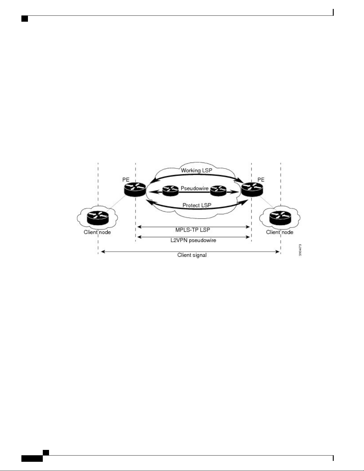
MPLS-TP Path Protection
MPLS-TP label switched paths (LSPs) support 1-to-1 path protection. There are two types of LSPs: protect
LSPs and working LSPs. You can configure the both types of LSPs when configuring the MPLS-TP tunnel.
The working LSP is the primary LSP used to route traffic. The protect LSP acts as a backup for a working
LSP. If the working LSP fails, traffic is switched to the protect LSP until the working LSP is restored, at
which time forwarding reverts back to the working LSP.
Bidirectional LSPs
Multiprotocol Label Switching Transport Profile (MPLS-TP) label switched paths (LSPs) are bidirectional
and co-routed. They comprise of two unidirectional LSPs that are supported by the MPLS forwarding
infrastructure. A TP tunnel consists of a pair of unidirectional tunnels that provide a bidirectional LSP. Each
unidirectional tunnel can be optionally protected with a protect LSP that activates automatically upon failure
conditions.
MPLS Basic Configuration Guide, Cisco IOS XE Everest 16.5.1 (Cisco ASR 900 Series)
12
Page 21

MPLS Transport Profile
MPLS Transport Profile Static and Dynamic Multisegment Pseudowires
MPLS Transport Profile Static and Dynamic Multisegment Pseudowires
Multiprotocol Label Switching Transport Profile (MPLS-TP) supports the following combinations of static
and dynamic multisegment pseudowires:
Dynamic-static
•
Static-dynamic
•
Static-static
•
MPLS-TP OAM Status for Static and Dynamic Multisegment Pseudowires
With static pseudowires, status notifications can be provided by BFD over VCCV or by the static pseudowire
OAM protocol. However, BFD over VCCV sends only attachment circuit status code notifications. Hop-by-hop
notifications of other pseudowire status codes are not supported. Therefore, the static pseudowire OAM
protocol is preferred
MPLS Transport Profile Links and Physical Interfaces
Multiprotocol Label Switching Transport Profile (MPLS-TP) link numbers may be assigned to physical
interfaces only. Bundled interfaces and virtual interfaces are not supported for MPLS-TP link numbers.
The MPLS-TP link creates a layer of indirection between the MPLS-TP tunnel and midpoint LSP configuration
and the physical interface. The mplstp link command is used to associate an MPLS-TP link number with a
physical interface and next-hop node. The MPLS-TP out-links can be configured only on the ethernet interfaces,
with either the next hop IPv4 address or next hop mac-address specified.
Multiple tunnels and LSPs may then refer to the MPLS-TP link to indicate that they are traversing that interface.
You can move the MPLS-TP link from one interface to another without reconfiguring all the MPLS-TP tunnels
and LSPs that refer to the link.
Link numbers must be unique on the router or node.
Tunnel Midpoints
Tunnel LSPs, whether endpoint or midpoint, use the same identifying information. However, it is entered
differently.
At the midpoint, all information for the LSP is specified with the mpls tp lsp command for configuring
•
forward and reverse information for forwarding.
At the midpoint, determining which end is source and which is destination is arbitrary. That is, if you
•
are configuring a tunnel between your device and a coworker’s device, then your device is the source.
However, your coworker considers his or her device to be the source. At the midpoint, either device
could be considered the source. At the midpoint, the forward direction is from source to destination, and
the reverse direction is from destination to source.
At the endpoint, the local information (source) either comes from the global device ID and global ID,
•
or from the locally configured information using the tp source command.
MPLS Basic Configuration Guide, Cisco IOS XE Everest 16.5.1 (Cisco ASR 900 Series)
13
Page 22
MPLS-TP Linear Protection with PSC Support
At the endpoint, the remote information (destination) is configured using the tp destination command
•
after you enter the interface tunnel-tp number command. The tp destination command includes the
destination node ID, and optionally the global ID and the destination tunnel number. If you do not specify
the destination tunnel number, the source tunnel number is used.
At the endpoint, the LSP number is configured in working-lsp or protect-lsp submode. The default is 0
•
for the working LSP and 1 for the protect LSP.
When configuring LSPs at midpoint devices, ensure that the configuration does not deflect traffic back
•
to the originating node.
MPLS-TP Linear Protection with PSC Support
MPLS-TP Linear Protection with PSC Support Overview
The Multiprotocol Label Switching (MPLS) Transport Profile (TP) enables you to create tunnels that provide
the transport network service layer over which IP and MPLS traffic traverse.
Network survivability is the ability of a network to recover traffic deliver following failure, or degradation,
of network resources. The MPLS-TP Survivability Framework (RFC-6372) describes the framework for
survivability in MPLS-TP networks, focusing on mechanisms for recovering MPLS-TP label switched paths
(LSPs)
Linear protection provides rapid and simple protection switching because it can operate between any pair of
points within a network. Protection switching is a fully allocated survivability mechanism, meaning that the
route and resources of the protection path are reserved for a selected working path or set of working paths.
For a point-to-point LSPs, the protected domain is defined as two label edge routers (LERs) and the transport
paths that connect them.
Protection switching in a point-to-point domain can be applied to a 1+1, 1:1, or 1:n unidirectional or
bidirectional protection architecture. When used for bidirectional switching, the protection architecture must
also support a Protection State Coordination (PSC) protocol. This protocol is used to help coordinate both
ends of the protected domain in selecting the proper traffic flow. For example, if either endpoint detects a
failure on the working transport entity, the endpoint sends a PSC message to inform the peer endpoint of the
state condition. The PSC protocol decides what local action, if any, should be taken.
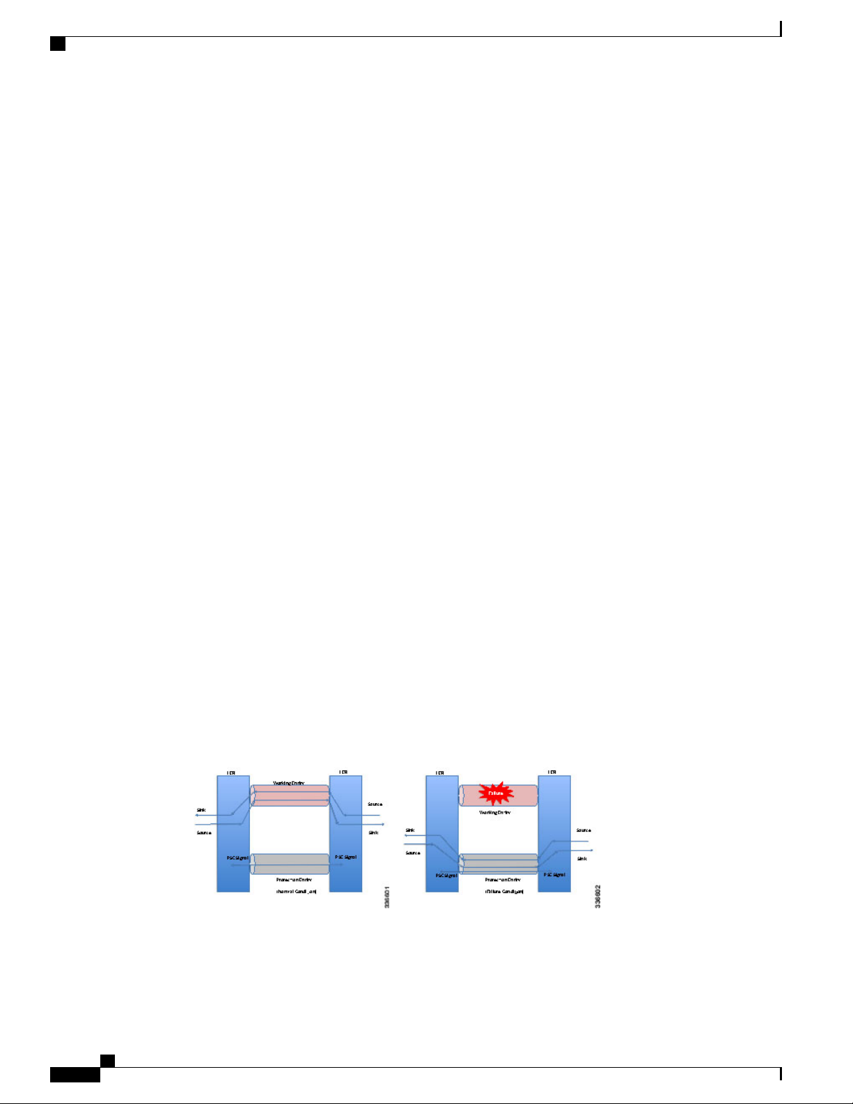
The following figure shows the MPLS-TP linear protection model used and the associated PSC signaling
channel for state coordination.
MPLS Transport Profile
In 1:1 bidirectional protection switching, for each direction, the source endpoint sends traffic on either a
working transport entity or a protected transport entity, referred to as a data-path. If the either endpoint detects
a failure on the working transport entity, that endpoint switches to send and receive traffic from the protected
MPLS Basic Configuration Guide, Cisco IOS XE Everest 16.5.1 (Cisco ASR 900 Series)
14
Page 23

MPLS Transport Profile
MPLS-TP Linear Protection with PSC Support
transport entity. Each endpoint also sends a PSC message to inform the peer endpoint of the state condition.
The PSC mechanism is necessary to coordinate the two transport entity endpoints and implement 1:1
bidirectional protection switching even for a unidirectional failure. The switching of the transport path from
working path to protected path can happen because of various failure conditions (such as link down indication
(LDI), remote defect indication (RDI), and link failures) or because administrator/operator intervention (such
as shutdown, lockout of working/forced switch (FS), and lockout of protection).
Each endpoint LER implements a PSC architecture that consists of multiple functional blocks. They are:
Local Trigger Logic: This receives inputs from bidirectional forwarding detection (BFD), operator
•
commands, fault operation, administration, and maintenance (OAM) and a wait-to-restore (WTR) timer.
It runs a priority logic to decide on the highest priority trigger.
PSC FSM: The highest priority trigger event drives the PSC finite state machine (FSM) logic to decide
•
what local action, if any, should be taken. These actions may include triggering path protection at the
local endpoint or may simply ignore the event.
Remote PSC Signaling: In addition to receiving events from local trigger logic, the PSC FSM logic
•
also receives and processes PSC signaling messages from the remote LER. Remote messages indicate
the status of the transport path from the viewpoint of the far end LER. These messages may drive state
changes on the local entity.
PSC Message Generator: Based on the action output from the PSC control logic, this functional block
•
formats the PSC protocol message and transmits it to the remote endpoint of the protected domain. This
message may either be the same as the previously transmitted message or change when the PSC control
has changed. The messages are transmitted as an initial burst followed by a regular interval.
Wait-to-Restore Timer: The (configurable) WTR timer is used to delay reversion to a normal state
•
when recovering from a failure condition on the working path in revertive mode. The PSC FSM logic
starts/stops the WTR timer based on internal conditions/state. When the WTR expires, it generates an
event to drive the local trigger logic.
Remote Event Expire Timer: The (configurable) remote-event-expire timer is used to clear the remote
•
event after the timer is expired because of remote inactivity or fault in the protected LSP. When the
remote event clear timer expires, it generates a remote event clear notification to the PSC FSM logic.
Interoperability With Proprietary Lockout
An emulated protection (emulated automatic protection switching (APS)) switching ensures synchronization
between peer entities. The emulated APS uses link down indication (LDI)message (proprietary) extensions
when a lockout command is issued on the working or protected LSP. This lockout command is known as
emLockout. A lockout is mutually exclusive between the working and protected LSP. In other words, when
the working LSP is locked, the protected LSP cannot be locked (and vice versa).
The emLockout message is sent on the specified channel from the endpoint on the LSP where the lockout
command (working/protected) is issued. Once the lockout is cleared locally, a Wait-To-Restore (WTR) timer
(configurable) is started and the remote end notified. The local peer continues to remain in lockout until a
clear is received from the remote peer and the WTR timer has expired and only then the LSP is considered
to be no longer locked out. In certain deployments, you use a large WTR timer to emulate a non-revertive
behavior. This causes the protected LSP to continue forwarding traffic even after the lockout has been removed
from the working LSP.
The PSC protocol as specified in RFC-6378 is incompatible with the emulated APS implementation in certain
conditions. For example, PSC implements a priority scheme whereby a lockout of protection (LoP) is at a
higher priority than a forced switch (FS) issued on a working LSP. When an FS is issued and cleared, PSC
MPLS Basic Configuration Guide, Cisco IOS XE Everest 16.5.1 (Cisco ASR 900 Series)
15
Page 24
MPLS-TP Linear Protection with PSC Support
states that the switching must revert to the working LSP immediately. However, the emulated APS
implementation starts a WTR timer and switches after the timer has expired.
An endpoint implementing the newer PSC version may have to communicate with another endpoint
implementing an older version. Because there is no mechanism to exchange the capabilities, the PSC
implementation must interoperate with another peer endpoint implementing emulated APS. In this scenario,
the new implementation sends both the LDI extension message (referred to as emLockout) as well as a PSC
message when the lockout is issued.
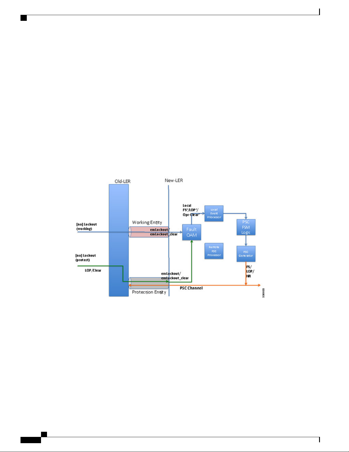
Mapping and Priority of emlockout
There are two possible setups for interoperability:
New-old implementation.
•
New-new implementation.
•
You can understand the mapping and priority when an emLockout is received and processed in the new-old
implementation by referring to the following figure.
MPLS Transport Profile
When the new label edge router (new-LER) receives an emLockout (or emLockout_clear) message, the
new-LER maps the message into an internal local FS’/FSc’ (local FS-prime/FS-prime-clear) or LoP’/LoPc’
(local LoP-prime/Lop-prime-clear) event based on the channel on which it is received. This event is prioritized
by the local event processor against any persistent local operator command. The highest priority event drives
the PSC FSM logic and any associated path protection logic. A new internal state is defined for FS’/FSc’
events. The PSC FSM logic transmits the corresponding PSC message. This message is dropped/ignored by
the old-LER.
In the new-new LER implementation shown in the following figure, each endpoint generates two messages
when a lockout command is given on a working or protected LSP.
MPLS Basic Configuration Guide, Cisco IOS XE Everest 16.5.1 (Cisco ASR 900 Series)
16
Page 25
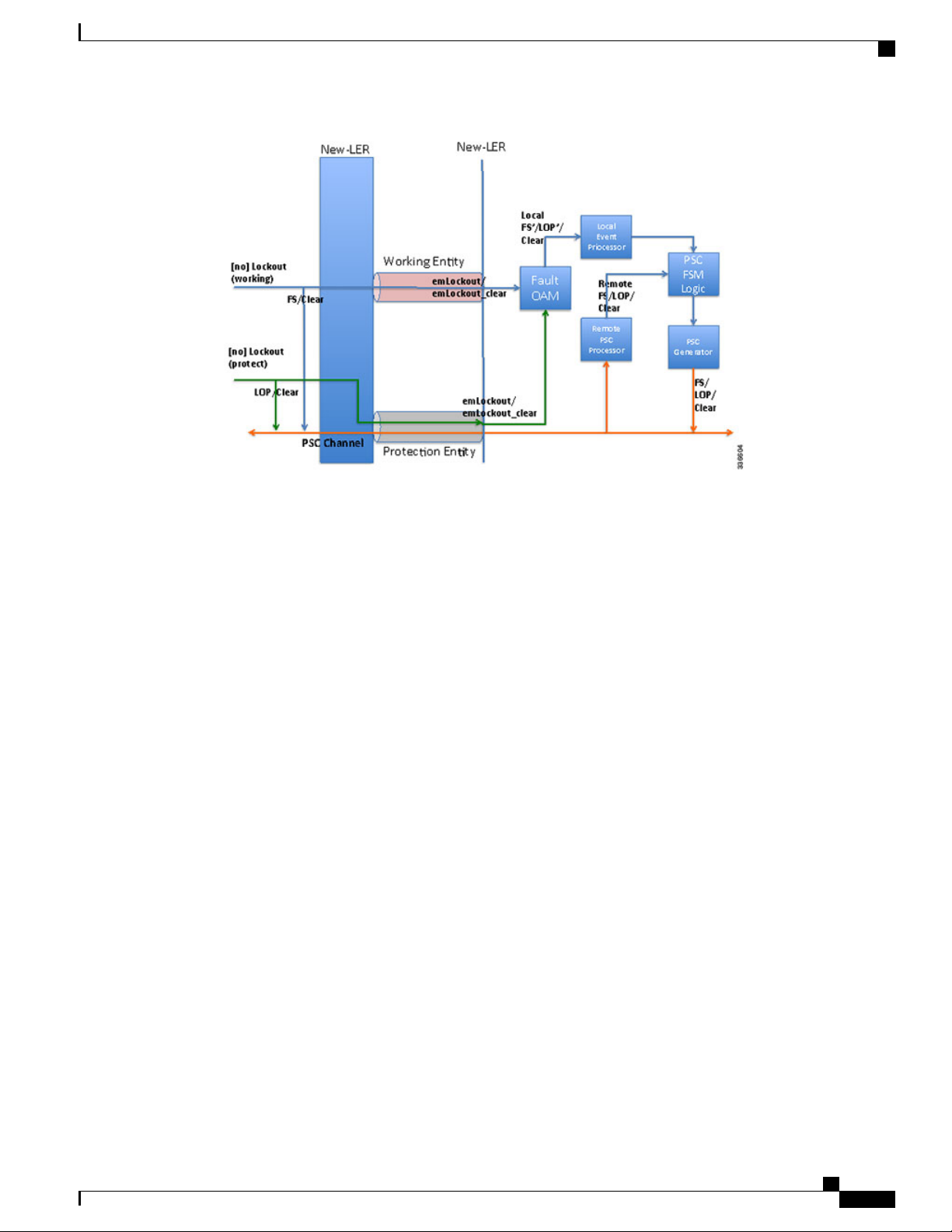
MPLS Transport Profile
MPLS-TP Linear Protection with PSC Support
When a lockout (working) command is issued, the new-LER implementation sends an emLockout command
on the working LSP and PSC(FS) on the protected LSP. The remote peer receives two commands in either
order. A priority scheme for local events is modified slightly beyond what is defined in order to drive the PSC
FSM to a consistent state despite the order in which the two messages are received.
In the new implementation, it is possible to override the lockout of the working LSP with the lockout of the
protected LSP according to the priority scheme. This is not allowed in the existing implementation. Consider
the following steps between old (O) and new (N) node setup:
Time T1: Lockout (on the working LSP) is issued on O and N. Data is switched from the working to the
protected LSP.
Time T2: Lockout (on the protected LSP) is issued on O and N. The command is rejected at O (existing
behavior) and accepted at N (new behavior). Data in O->N continues on the protected LSP. Data in N->O
switches to the working LSP.
You must issue a clear lockout (on the working LSP) and re-issue a lockout (on the protected LSP) on the old
node to restore consistency.
WTR Synchronization
When a lockout on the working label switched path (LSP) is issued and subsequently cleared, a WTR timer
(default: 10 sec, configurable) is started. When the timer expires, the data path is switched from protected to
working LSP.
The PSC protocol indicates that the switch should happen immediately when a lockout (FS) is cleared.
When a new node is connected to the old node, for a period of time equal to the WTR timer value, the data
path may be out-of-sync when a lockout is cleared on the working LSP. You should configure a low WTR
value in order to minimize this condition.
Another issue is synchronization of the WTR value during stateful switchover (SSO). Currently, the WTR
residual value is not checkpointed between the active and standby. As a result, after SSO, the new active
restarts the WTR with the configured value if the protected LSP is active and the working LSP is up. As part
of the PSC protocol implementation, the residual WTR is checkpointed on the standby. When the standby
becomes active, the WTR is started with the residual value.
MPLS Basic Configuration Guide, Cisco IOS XE Everest 16.5.1 (Cisco ASR 900 Series)
17
Page 26

How to Configure MPLS Transport Profile
Priority of Inputs
The event priority scheme for locally generated events is as follows in high to low order:
Local Events:
1. Opr-Clear (Operator Clear)
2. LoP (Lockout of Protection)
3. LoP’/LoP’-Clear
4. FS (Forced Switch)
5. FS’/FS’-Clear
6. MS (Manual-Switch)
The emLockout received on the working LSP is mapped to the local-FS’. The emLockout received on the
protected LSP is mapped to the local-LoP’. The emLockout-clear received is mapped to the corresponding
clear events.
The priority definition for Signal Fail (SF), Signal Degrade (SD), Manual Switch (MS), WTR, Do Not Revert
(DNR), and No Request (NR) remains unchanged.
MPLS Transport Profile
PSC Syslogs
The following are the new syslogs that are introduced as part of the Linear Protection with PSC Support
feature:
MPLS_TP_TUNNEL_PSC_PREEMPTION
MPLS_TP_TUNNEL_PSC_TYPE_MISMATCH
Handle MPLS TP tunnel
PSC event preemption
syslog.
Handle MPLS TP tunnel
type mismatch
How to Configure MPLS Transport Profile
Configuring the MPLS Label Range
You must specify a static range of Multiprotocol Label Switching (MPLS) labels using the mpls label range
command with the static keyword.
RAW FORMATDESCRIPTIONSYSLOG NAME
%MPLS-TP-5-PSCPREEMPTION:
Tunnel-tp10, PSC Event:
LOP:R preempted PSC Event:
FS:L
%MPLS-PSC-5-TYPE-MISMATCH:
Tunnel-tp10, type mismatch
local-type: 1:1,
MPLS Basic Configuration Guide, Cisco IOS XE Everest 16.5.1 (Cisco ASR 900 Series)
18
Page 27

MPLS Transport Profile
SUMMARY STEPS
DETAILED STEPS
Configuring the MPLS Label Range
enable
1.
configure terminal
2.
mpls label range minimum-value maximum-value static minimum-static-value maximum-static-value
3.
end
4.
PurposeCommand or Action
Step 1
Step 2
Step 3
Step 4
Example:
Device> enable
Example:
Device# configure terminal
mpls label range minimum-value maximum-value static
minimum-static-value maximum-static-value
Example:
Device(config)# mpls label range 1001 1003 static
10000 25000
end
Example:
Device(config)# end
Enables privileged EXEC mode.enable
Enter your password if prompted.
•
Enters global configuration mode.configure terminal
Specifies a static range of MPLS labels.
Exits global configuration mode and returns to
privileged EXEC mode.
MPLS Basic Configuration Guide, Cisco IOS XE Everest 16.5.1 (Cisco ASR 900 Series)
19
Page 28

Configuring the Router ID and Global ID
Configuring the Router ID and Global ID
SUMMARY STEPS
enable
1.
configure terminal
2.
mpls tp
3.
router-id node-id
4.
global-id num
5.
end
6.
DETAILED STEPS
PurposeCommand or Action
MPLS Transport Profile
Step 1
Step 2
Step 3
Step 4
Step 5
Example:
Device> enable
Example:
Device# configure terminal
mpls tp
Example:
Device(config)# mpls tp
router-id node-id
Example:
Device(config-mpls-tp)# router-id
10.10.10.10
global-id num
Example:
Device(config-mpls-tp)# global-id 1
Enables privileged EXEC mode.enable
Enter your password if prompted.
•
Enters global configuration mode.configure terminal
Enters MPLS-TP configuration mode, from which you can configure
MPLS-TP parameters for the device.
Specifies the default MPLS-TP router ID, which is used as the default
source node ID for all MPLS-TP tunnels configured on the device.
(Optional) Specifies the default global ID used for all endpoints and
midpoints.
This command makes the router ID globally unique in a multiprovider
•
tunnel. Otherwise, the router ID is only locally meaningful.
The global ID is an autonomous system number, which is a controlled
•
number space by which providers can identify each other.
MPLS Basic Configuration Guide, Cisco IOS XE Everest 16.5.1 (Cisco ASR 900 Series)
20
Page 29

MPLS Transport Profile
Configuring Bidirectional Forwarding Detection Templates
PurposeCommand or Action
The router ID and global ID are also included in fault messages sent
•
by devices from the tunnel midpoints to help isolate the location of
faults.
Step 6
Example:
Device(config-mpls-tp)# end
Exits MPLS-TP configuration mode and returns to privileged EXEC mode.end
Configuring Bidirectional Forwarding Detection Templates
The bfd-template command allows you to create a BFD template and enter BFD configuration mode. The
template can be used to specify a set of BFD interval values. You invoke the template as part of the MPLS-TP
tunnel. On platforms that support the BFD Hardware Offload feature and that can provide a 60-ms cutover
for MPLS-TP tunnels, it is recommended to use the higher resolution timers in the BFD template.
SUMMARY STEPS
enable
1.
configure terminal
2.
bfd-template single-hop template-name
3.
interval [microseconds] {both time | min-tx time min-rx time} [multiplier multiplier-value]
4.
end
5.
DETAILED STEPS
Step 1
Step 2
Example:
Device> enable
Example:
Device# configure terminal
PurposeCommand or Action
Enables privileged EXEC mode.enable
Enter your password if prompted.
•
Enters global configuration mode.configure terminal
MPLS Basic Configuration Guide, Cisco IOS XE Everest 16.5.1 (Cisco ASR 900 Series)
21
Page 30

Configuring Pseudowire OAM Attributes
MPLS Transport Profile
PurposeCommand or Action
Step 3
Step 4
bfd-template single-hop template-name
Example:
Device(config)# bfd-template single-hop mpls-bfd-1
interval [microseconds] {both time | min-tx time min-rx
time} [multiplier multiplier-value]
Example:
Device(config-bfd)# interval min-tx 99 min-rx 99
multiplier 3
Step 5
end
Example:
Device(config-bfd)# exit
Configuring Pseudowire OAM Attributes
Creates a BFD template and enter BFD configuration
mode.
Specifies a set of BFD interval values.
Exits BFD configuration mode and returns to
privileged EXEC mode.
SUMMARY STEPS
DETAILED STEPS
Step 1
Step 2
enable
1.
configure terminal
2.
pseudowire-static-oam class class-name
3.
timeout refresh send seconds
4.
exit
5.
Example:
Device> enable
Example:
Device# configure terminal
PurposeCommand or Action
Enables privileged EXEC mode.enable
Enter your password if prompted.
•
Enters global configuration mode.configure terminal
MPLS Basic Configuration Guide, Cisco IOS XE Everest 16.5.1 (Cisco ASR 900 Series)
22
Page 31

MPLS Transport Profile
Configuring the Pseudowire Class
PurposeCommand or Action
Step 3
Step 4
Step 5
pseudowire-static-oam class class-name
Example:
Device(config)# pseudowire-static-oam class
oam-class1
timeout refresh send seconds
Example:
Device(config-st-pw-oam-class)# timeout refresh
send 20
exit
Example:
Device(config-st-pw-oam-class)# exit
Configuring the Pseudowire Class
When you create a pseudowire class, you specify the parameters of the pseudowire, such as the use of the
control word, preferred path and OAM class template.
Creates a pseudowire OAM class and enters pseudowire
OAM class configuration mode.
Specifies the OAM timeout refresh interval.
Exits pseudowire OAM configuration mode and returns
to privileged EXEC mode.
SUMMARY STEPS
DETAILED STEPS
Step 1
enable
1.
configure terminal
2.
pseudowire-class class-name
3.
encapsulation mpls
4.
control-word
5.
mpls label protocol [ldp | none]
6.
preferred-path {interface tunnel tunnel-number | peer {ip-address | host-name}} [disable-fallback]
7.
status protocol notification static class-name
8.
end
9.
PurposeCommand or Action
Enables privileged EXEC mode.enable
MPLS Basic Configuration Guide, Cisco IOS XE Everest 16.5.1 (Cisco ASR 900 Series)
23
Page 32

Configuring the Pseudowire Class
Example:
Device> enable
PurposeCommand or Action
Enter your password if prompted.
•
MPLS Transport Profile
Step 2
Step 3
Step 4
Step 5
Step 6
Example:
Device# configure terminal
pseudowire-class class-name
Example:
Device(config)# pseudowire-class mpls-tp-class1
Example:
Device(config-pw-class)# encapsulation mpls
Example:
Device(config-pw-class)# control-word
Enters global configuration mode.configure terminal
Creates a pseudowire class and enters pseudowire
class configuration mode.
Specifies the encapsulation type.encapsulation mpls
Enables the use of the control word.control-word
Specifies the type of protocol.mpls label protocol [ldp | none]
Step 7
Step 8
24
Example:
Device(config-pw-class)# protocol none
preferred-path {interface tunnel tunnel-number | peer
{ip-address | host-name}} [disable-fallback]
Example:
Device(config-pw-class)# preferred-path interface
tunnel-tp2
status protocol notification static class-name
Example:
Device(config-pw-class)# status protocol notification
static oam-class1
MPLS Basic Configuration Guide, Cisco IOS XE Everest 16.5.1 (Cisco ASR 900 Series)
Specifies the tunnel to use as the preferred path.
Specifies the OAM class to use.
Page 33

MPLS Transport Profile
Configuring the Pseudowire
PurposeCommand or Action
Step 9
end
Example:
Device(config-pw-class)# end
Configuring the Pseudowire
SUMMARY STEPS
enable
1.
configure terminal
2.
interfaceinterface-id
3.
service instance number ethernet [name]
4.
mpls label local-pseudowire-label remote-pseudowire-label
5.
mpls control-word
6.
backup delay {enable-delay-period | never} {disable-delay-period | never}
7.
backup peer peer-router-ip-addr vcid [pw-class pw-class-name] [priority value]
8.
end
9.
Exits pseudowire class configuration mode and
returns to privileged EXEC mode.
DETAILED STEPS
Step 1
Example:
Device> enable
Step 2
Example:
Device# configure terminal
Step 3
interfaceinterface-id
Example:
Router(config)# interface gigabitethernet
0/0/4
PurposeCommand or Action
Enables privileged EXEC mode.enable
Enter your password if prompted.
•
Enters global configuration mode.configure terminal
Specifies the port on which to create the pseudowire and enters
interface configuration mode. Valid interfaces are physical Ethernet
ports.
MPLS Basic Configuration Guide, Cisco IOS XE Everest 16.5.1 (Cisco ASR 900 Series)
25
Page 34

Configuring the Pseudowire
MPLS Transport Profile
PurposeCommand or Action
Step 4
Step 5
Step 6
service instance number ethernet [name]
Example:
Router(config-if)# service instance 2
ethernet
mpls label local-pseudowire-label
remote-pseudowire-label
Example:
Device(config-if-xconn)# mpls label 1000
1001
Configure an EFP (service instance) and enter service instance
configuration) mode.
• number—Indicates EFP identifier. Valid values are from 1
to 400
• (Optional) ethernet name—Name of a previously configured
EVC. You do not need to use an EVC name in a service
instance.
Note
You can use service instance settings such as
encapsulation, dot1q, and rewrite to configure
tagging properties for a specific traffic flow within
a given pseudowire session. For more information,
see Ethernet Virtual Connections on the Cisco ASR
903 Router.
Configures the static pseudowire connection by defining local and
remote circuit labels.
Specifies the control word.mpls control-word
Step 7
Step 8
Step 9
Example:
Device(config-if-xconn)# no mpls
control-word
backup delay {enable-delay-period | never}
{disable-delay-period | never}
Example:
Device(config-if-xconn)# backup delay 0
never
backup peer peer-router-ip-addr vcid [pw-class
pw-class-name] [priority value]
Example:
Device(config-if-xconn)# backup peer
10.0.0.2 50
end
Example:
Device(config)# end
Specifies how long a backup pseudowire virtual circuit (VC)
should wait before resuming operation after the primary
pseudowire VC goes down.
Specifies a redundant peer for a pseudowire virtual circuit (VC).
Exits xconn interface connection mode and returns to privileged
EXEC mode.
MPLS Basic Configuration Guide, Cisco IOS XE Everest 16.5.1 (Cisco ASR 900 Series)
26
Page 35

MPLS Transport Profile
Configuring the MPLS-TP Tunnel
On the endpoint devices, create an MPLS TP tunnel and configure its parameters. See the interface tunnel-tp
command for information on the parameters.
SUMMARY STEPS
enable
1.
configure terminal
2.
interface tunnel-tp number
3.
description tunnel-description
4.
tp tunnel-name name
5.
tp source node-id [global-id num]
6.
tp destination node-id [tunnel-tp num[ global-id num]]
7.
bfd bfd-template
8.
working-lsp
9.
in-label num
10.
out-label num out-link num
11.
exit
12.
protect-lsp
13.
in-label num
14.
out-label num out-link num
15.
end
16.
Configuring the MPLS-TP Tunnel
DETAILED STEPS
Step 1
Step 2
Example:
Device> enable
Example:
Device# configure terminal
PurposeCommand or Action
Enables privileged EXEC mode.enable
Enter your password if prompted.
•
Enters global configuration mode.configure terminal
MPLS Basic Configuration Guide, Cisco IOS XE Everest 16.5.1 (Cisco ASR 900 Series)
27
Page 36

Configuring the MPLS-TP Tunnel
MPLS Transport Profile
PurposeCommand or Action
Step 3
Step 4
Step 5
Step 6
Step 7
interface tunnel-tp number
Example:
Device(config)# interface tunnel-tp 1
description tunnel-description
Example:
Device(config-if)# description headend tunnel
tp tunnel-name name
Example:
Device(config-if)# tp tunnel-name tunnel 122
tp source node-id [global-id num]
Example:
Device(config-if)# tp source 10.11.11.11 global-id
10
tp destination node-id [tunnel-tp num[ global-id num]]
Enters tunnel interface configuration mode. Tunnel
numbers from 0 to 999 are supported.
(Optional) Specifies a tunnel description.
Specifies the name of the MPLS-TP tunnel.
(Optional) Specifies the tunnel source and endpoint.
Specifies the destination node of the tunnel.
Step 8
Step 9
Step 10
Example:
Device(config-if)# tp destination 10.10.10.10
bfd bfd-template
Example:
Device(config-if)# bfd mpls-bfd-1
working-lsp
Example:
Device(config-if)# working-lsp
in-label num
Example:
Device(config-if-working)# in-label 20000
Specifies the BFD template.
Specifies a working LSP, also known as the primary
LSP.
Specifies the in-label number.
MPLS Basic Configuration Guide, Cisco IOS XE Everest 16.5.1 (Cisco ASR 900 Series)
28
Page 37

MPLS Transport Profile
Configuring MPLS-TP LSPs at Midpoints
PurposeCommand or Action
Step 11
Step 12
Step 13
Step 14
Step 15
out-label num out-link num
Example:
Device(config-if-working)# out-label 20000 out-link
exit
Example:
Device(config-if-working)# exit
Example:
Device(config-if)# protect-lsp
in-label num
Example:
Device(config-if-protect)# in-label 20000
out-label num out-link num
Specifies the out-label number and out-link.
Exits working LSP interface configuration mode and
returns to interface configuration mode.
Specifies a backup for a working LSP.protect-lsp
Specifies the in label.
Specifies the out label and out link.
Example:
Device(config-if-protect)# out-label 113 out-link
Step 16
end
Example:
Device(config-if-protect)# end
Configuring MPLS-TP LSPs at Midpoints
Note
When configuring LSPs at midpoint devices, ensure that the configuration does not deflect traffic back
to the originating node.
Exits the interface configuration mode and returns
to privileged EXEC mode.
MPLS Basic Configuration Guide, Cisco IOS XE Everest 16.5.1 (Cisco ASR 900 Series)
29
Page 38

Configuring MPLS-TP LSPs at Midpoints
SUMMARY STEPS
DETAILED STEPS
MPLS Transport Profile
enable
1.
configure terminal
2.
mpls tp lsp source node-id [global-id num] tunnel-tp num lsp{lsp-num | protect | working} destination
3.
node-id [global-id num] tunnel-tp num
forward-lsp
4.
in-label num out-label num out-link num
5.
exit
6.
reverse-lsp
7.
in-label num out-label num out-link num
8.
end
9.
Step 1
Step 2
Step 3
Step 4
Example:
Device> enable
Example:
Device# configure terminal
mpls tp lsp source node-id [global-id num] tunnel-tp num
lsp{lsp-num | protect | working} destination node-id
[global-id num] tunnel-tp num
Example:
Device(config)# mpls tp lsp source 10.10.10.10
global-id 10 tunnel-tp 1 lsp protect destination
10.11.11.11 global-id 10 tunnel-tp 1
forward-lsp
Example:
PurposeCommand or Action
Enables privileged EXEC mode.enable
Enter your password if prompted.
•
Enters global configuration mode.configure terminal
Enables MPLS-TP midpoint connectivity and enters
MPLS TP LSP configuration mode.
Enters MPLS-TP LSP forward LSP configuration
mode.
Step 5
30
Device(config-mpls-tp-lsp)# forward-lsp
in-label num out-label num out-link num
Example:
Device(config-mpls-tp-lsp-forw)# in-label 2000
out-label 2100 out-link 41
MPLS Basic Configuration Guide, Cisco IOS XE Everest 16.5.1 (Cisco ASR 900 Series)
Specifies the in label, out label, and out link numbers.
Page 39

MPLS Transport Profile
Configuring MPLS-TP Links and Physical Interfaces
PurposeCommand or Action
Step 6
Step 7
Step 8
Step 9
exit
Example:
Device(config-mpls-tp-lsp-forw)# exit
reverse-lsp
Example:
Device(config-mpls-tp-lsp)# reverse-lsp
in-label num out-label num out-link num
Example:
Device(config-mpls-tp-lsp-rev)# in-label 22000
out-label 20000 out-link 44
end
Example:
Device(config-mpls-tp-lsp-rev)# end
Exits MPLS-TP LSP forward LSP configuration
mode.
Enters MPLS-TP LSP reverse LSP configuration
mode.
Specifies the in-label, out-label, and out-link
numbers.
Exits the MPLS TP LSP configuration mode and
returns to privileged EXEC mode.
Configuring MPLS-TP Links and Physical Interfaces
MPLS-TP link numbers may be assigned to physical interfaces only. Bundled interfaces and virtual interfaces
are not supported for MPLS-TP link numbers.
SUMMARY STEPS
enable
1.
configure terminal
2.
interface type number
3.
ip address ip-address mask
4.
mpls tp link link-num{ipv4 ip-address tx-mac mac-address}
5.
end
6.
DETAILED STEPS
PurposeCommand or Action
Step 1
Enables privileged EXEC mode.enable
MPLS Basic Configuration Guide, Cisco IOS XE Everest 16.5.1 (Cisco ASR 900 Series)
31
Page 40

Configuring MPLS-TP Linear Protection with PSC Support
Example:
Device> enable
PurposeCommand or Action
Enter your password if prompted.
•
MPLS Transport Profile
Step 2
Step 3
Step 4
Step 5
Example:
Device# configure terminal
interface type number
Example:
Device(config)# interface ethernet 1/0
ip address ip-address mask
Example:
Device(config-if)# ip address
10.10.10.10 255.255.255.0
mpls tp link link-num{ipv4 ip-address tx-mac
mac-address}
Example:
Device(config-if)# mpls tp link 1 ipv4
10.0.0.2
Enters global configuration mode.configure terminal
Specifies the interface and enters interface configuration mode.
Assigns an IP address to the interface.
Associates an MPLS-TP link number with a physical interface and
next-hop node. On point-to-point interfaces or Ethernet interfaces
designated as point-to-point using the medium p2pcommand, the
next-hop can be implicit, so the mpls tp linkcommand just associates
a link number to the interface.
Multiple tunnels and LSPs can refer to the MPLS-TP link to indicate
they are traversing that interface. You can move the MPLS-TP link
from one interface to another without reconfiguring all the MPLS-TP
tunnels and LSPs that refer to the link.
Link numbers must be unique on the device or node.
Step 6
end
Exits interface configuration mode and returns to privileged EXEC
mode.
Example:
Device(config-if)# end
Configuring MPLS-TP Linear Protection with PSC Support
The psc command allows you to configure MPLS-TP linear protection with PSC support. PSC is disabled by
default. However, it can be enabled by issuing the psc command.
MPLS Basic Configuration Guide, Cisco IOS XE Everest 16.5.1 (Cisco ASR 900 Series)
32
Page 41

MPLS Transport Profile
SUMMARY STEPS
Configuring MPLS-TP Linear Protection with PSC Support
enable
1.
configure terminal
2.
mpls tp
3.
psc
4.
psc fast refresh interval time-in-msec
5.
psc slow refresh interval time-in-msec
6.
psc remote refresh interval time-in-sec message-count num
7.
exit
8.
interface tunnel-tp number
9.
psc
10.
emulated-lockout
11.
working-lsp
12.
manual-switch
13.
exit
14.
exit
15.
DETAILED STEPS
Step 1
Step 2
Step 3
Step 4
Example:
Device> enable
Example:
Device# configure terminal
mpls tp
Example:
Device(config)# mpls tp
Example:
PurposeCommand or Action
Enables privileged EXEC mode.enable
Enter your password if prompted.
•
Enters global configuration mode.configure terminal
Enters Multiprotocol Label Switching (MPLS) Transport Profile
(TP) global mode.
Enables the PSC Protocol.psc
Step 5
Device(config-mpls-tp)# psc
psc fast refresh interval time-in-msec
MPLS Basic Configuration Guide, Cisco IOS XE Everest 16.5.1 (Cisco ASR 900 Series)
Configures the fast refresh interval for PSC messages.
33
Page 42

Configuring MPLS-TP Linear Protection with PSC Support
Example:
Device(config-mpls-tp)# psc fast refresh
interval 2000
MPLS Transport Profile
PurposeCommand or Action
The default is 1000 ms with a jitter of 50 percent. The
•
range is from 1000 ms to 5000 sec.
Step 6
Step 7
Step 8
Step 9
psc slow refresh interval time-in-msec
Example:
Device(config-mpls-tp)# psc slow refresh
interval 10
psc remote refresh interval time-in-sec
message-count num
Example:
Device(config-mpls-tp)# psc remote refresh
interval 20 message-count 15
Example:
Device(config-mpls-tp)# exit
interface tunnel-tp number
Example:
Device(config)# interface tunnel-tp 1
Configures the slow refresh interval for PSC messages.
The default is 5 sec. The range is from 5 secs to 86400
•
secs (24 hours).
Configures the remote-event expiration timer.
By default, this timer is disabled. The remote refresh
•
interval range is from 5 to 86400 sec (24 hours). The
message count is from 5 to 1000. If you do not specify the
message count value, it is set to 5, which is the default.
Exits MPLS TP global mode.exit
Creates an MPLS-TP tunnel called number and enters TP
interface tunnel mode.
Step 10
Step 11
Step 12
34
Enables PSC.psc
By default, PSC is disabled.
Example:
Device(config-if)# psc
emulated-lockout
Enables the sending of emLockout on working/protected
transport entities if the lockout command is issued on each
Example:
working/protected transport entity respectively. By default, the
sending of emLockout is disabled.
Device(config-if)# emulated-lockout
Enters working LSP mode on a TP tunnel interface.working-lsp
Example:
Device(config-if)# working-lsp
MPLS Basic Configuration Guide, Cisco IOS XE Everest 16.5.1 (Cisco ASR 900 Series)
Page 43

MPLS Transport Profile
Configuring Static-to-Static Multisegment Pseudowires for MPLS-TP
PurposeCommand or Action
Step 13
manual-switch
Issues a local manual switch condition on a working label
switched path (LSP). This can be configured only in working
Example:
Device(config-if-working)# manual-switch
Step 14
Example:
Device(config-if-working)# exit
Step 15
Example:
Device(config-if)# exit
LSP mode on a TP tunnel interface.
Exits working LSP mode.exit
Exits TP interface tunnel mode.exit
Configuring Static-to-Static Multisegment Pseudowires for MPLS-TP
SUMMARY STEPS
enable
1.
configure terminal
2.
l2 vfi name point-to-point
3.
bridge-domainbridge-id
4.
neighbor ip-address vc-id {encapsulation mpls | pw-class pw-class-name}
5.
mpls label local-pseudowire-label remote-pseudowire-label
6.
mpls control-word
7.
neighbor ip-address vc-id {encapsulation mpls | pw-class pw-class-name}
8.
mpls label local-pseudowire-label remote-pseudowire-label
9.
mpls control-word
10.
end
11.
DETAILED STEPS
Step 1
Example:
Device> enable
PurposeCommand or Action
Enables privileged EXEC mode.enable
Enter your password if prompted.
•
MPLS Basic Configuration Guide, Cisco IOS XE Everest 16.5.1 (Cisco ASR 900 Series)
35
Page 44

Configuring Static-to-Static Multisegment Pseudowires for MPLS-TP
MPLS Transport Profile
PurposeCommand or Action
Step 2
Step 3
Step 4
Step 5
Step 6
Example:
Device# configure terminal
l2 vfi name point-to-point
Example:
Device(config)# l2 vfi atom point-to-point
bridge-domainbridge-id
Example:
Device)config)# bridge-domain 400
neighbor ip-address vc-id {encapsulation mpls |
pw-class pw-class-name}
Example:
Device(config-vfi)# neighbor 10.111.111.111 123
pw-class atom
mpls label local-pseudowire-label
remote-pseudowire-label
Enters global configuration mode.configure terminal
Creates a point-to-point Layer 2 virtual forwarding interface
(VFI) and enters VFI configuration mode.
Configures the bridge domain service instance.
• bridge-id—Bridge domain identifier. The valid values
are from 1 to 4000.
Sets up an emulated VC. Specify the IP address, the VC ID
of the remote device, and the pseudowire class to use for
the emulated VC.
Note
Only two neighbor commands are allowed for
each Layer 2 VFI point-to-point command.
Configures the static pseudowire connection by defining
local and remote circuit labels.
Step 7
Step 8
Step 9
Example:
Device(config-vfi)# mpls label 10000 25000
Example:
Device(config-vfi)# mpls control-word
neighbor ip-address vc-id {encapsulation mpls |
pw-class pw-class-name}
Example:
Device(config-vfi)# neighbor 10.10.10.11 123
pw-class atom
mpls label local-pseudowire-label
remote-pseudowire-label
Example:
Device(config-vfi)# mpls label 11000 11001
Specifies the control word.mpls control-word
Sets up an emulated VC. Specify the IP address, the VC ID
of the remote device, and the pseudowire class to use for
the emulated VC.
Configures the static pseudowire connection by defining
local and remote circuit labels.
MPLS Basic Configuration Guide, Cisco IOS XE Everest 16.5.1 (Cisco ASR 900 Series)
36
Page 45

MPLS Transport Profile
Configuring Static-to-Dynamic Multisegment Pseudowires for MPLS-TP
PurposeCommand or Action
Step 10
Step 11
Example:
Example:
Device(config-vfi)# mpls control-word
end
Specifies the control word.mpls control-word
Exits VFI configuration mode and returns to privileged
EXEC mode.
Example:
Device(config)# end
Configuring Static-to-Dynamic Multisegment Pseudowires for MPLS-TP
When you configure static-to-dynamic pseudowires, you configure the static pseudowire class with the protocol
none command, create a dynamic pseudowire class, and then invoke those pseudowire classes with the neighbor
commands.
MPLS Basic Configuration Guide, Cisco IOS XE Everest 16.5.1 (Cisco ASR 900 Series)
37
Page 46

Configuring Static-to-Dynamic Multisegment Pseudowires for MPLS-TP
SUMMARY STEPS
enable
1.
configure terminal
2.
pseudowire-class class-name
3.
encapsulation mpls
4.
control-word
5.
mpls label protocol [ldp | none]
6.
exit
7.
pseudowire-class class-name
8.
encapsulation mpls
9.
exit
10.
l2 vfi name point-to-point
11.
neighbor ip-address vc-id {encapsulation mpls | pw-class pw-class-name}
12.
neighbor ip-address vc-id {encapsulation mpls | pw-class pw-class-name}
13.
mpls label local-pseudowire-label remote-pseudowire-label
14.
mpls control-word
15.
local interface pseudowire-type
16.
Do one of the following:
17.
MPLS Transport Profile
DETAILED STEPS
Step 1
Step 2
Step 3
tlv [type-name] type-value length [dec | hexstr | str] value
•
tlv template template-name
•
end
18.
Example:
Device> enable
Example:
Device# configure terminal
pseudowire-class class-name
Example:
PurposeCommand or Action
Enables privileged EXEC mode.enable
Enter your password if prompted.
•
Enters global configuration mode.configure terminal
Creates a pseudowire class and enters pseudowire class
configuration mode.
Device(config)# pseudowire-class mpls-tp-class1
MPLS Basic Configuration Guide, Cisco IOS XE Everest 16.5.1 (Cisco ASR 900 Series)
38
Page 47

MPLS Transport Profile
Configuring Static-to-Dynamic Multisegment Pseudowires for MPLS-TP
PurposeCommand or Action
Step 4
Step 5
Step 6
Step 7
Step 8
Example:
Device(config-pw-class)# encapsulation mpls
Example:
Device(config-pw-class)# control-word
Example:
Device(config-pw-class)# protocol none
exit
Example:
Device(config-pw-class)# exit
pseudowire-class class-name
Example:
Specifies the encapsulation type.encapsulation mpls
Enables the use of the control word.control-word
Specifies the type of protocol.mpls label protocol [ldp | none]
Exits pseudowire class configuration mode and returns
to global configuration mode.
Creates a pseudowire class and enters pseudowire class
configuration mode.
Step 9
Step 10
Step 11
Step 12
Device(config)# pseudowire-class mpls-tp-class1
Example:
Device(config-pw-class)# encapsulation mpls
exit
Example:
Device(config-pw-class)# exit
l2 vfi name point-to-point
Example:
Device(config)# l2 vfi atom point-to-point
neighbor ip-address vc-id {encapsulation mpls | pw-class
pw-class-name}
Specifies the encapsulation type.encapsulation mpls
Exits pseudowire class configuration mode and returns
to global configuration mode.
Creates a point-to-point Layer 2 virtual forwarding
interface (VFI) and enters VFI configuration mode.
Sets up an emulated VC and enters VFI neighbor
configuration mode.
MPLS Basic Configuration Guide, Cisco IOS XE Everest 16.5.1 (Cisco ASR 900 Series)
39
Page 48

Configuring Static-to-Dynamic Multisegment Pseudowires for MPLS-TP
Example:
Device(config-vfi)# neighbor 10.111.111.111 123
pw-class atom
PurposeCommand or Action
Note
MPLS Transport Profile
Note: Only two neighbor commands are
allowed for each l2 vfi point-to-point
command.
Step 13
Step 14
Step 15
Step 16
Step 17
neighbor ip-address vc-id {encapsulation mpls | pw-class
pw-class-name}
Example:
Device(config-vfi-neighbor)# neighbor
10.111.111.111 123 pw-class atom
mpls label local-pseudowire-label remote-pseudowire-label
Example:
Device(config-vfi-neighbor)# mpls label 10000 25000
Example:
Device(config-vfi-neighbor)# mpls control-word
local interface pseudowire-type
Example:
Device(config-vfi-neighbor)# local interface 4
Do one of the following:
tlv [type-name] type-value length [dec | hexstr | str]
•
value
Sets up an emulated VC.
Note
Only two neighbor commands are allowed
for each l2 vfi point-to-point command.
Configures the static pseudowire connection by
defining local and remote circuit labels.
Specifies the control word.mpls control-word
Specifies the pseudowire type.
Specifies the TLV parameters or invokes a previously
configured TLV template.
Step 18
40
tlv template template-name
•
Example:
Device(config-vfi-neighbor)# tlv statictemp 2 4
hexstr 1
Ends the session.end
Example:
Device(config-vfi-neighbor)# end
MPLS Basic Configuration Guide, Cisco IOS XE Everest 16.5.1 (Cisco ASR 900 Series)
Page 49

MPLS Transport Profile
Configuring a Template with Pseudowire Type-Length-Value Parameters
Configuring a Template with Pseudowire Type-Length-Value Parameters
SUMMARY STEPS
enable
1.
configure terminal
2.
tlv [type-name] type-value length [dec | hexstr | str] value
3.
end
4.
DETAILED STEPS
PurposeCommand or Action
Step 1
Step 2
Step 3
Step 4
Example:
Device> enable
Example:
Device# configure terminal
tlv [type-name] type-value length [dec | hexstr | str] value
Example:
Device(config-pw-tlv-template)# tlv statictemp 2
4 hexstr 1
end
Example:
Device(config-pw-tlv-template)# end
Enables privileged EXEC mode.enable
Enter your password if prompted.
•
Enters global configuration mode.configure terminal
Specifies the TLV parameters.
Exits pseudowire TLV template configuration mode
and returns to privileged EXEC mode.
Verifying the MPLS-TP Configuration
Use the following commands to verify and help troubleshoot your MPLS-TP configuration:
• debug mpls tp—Enables the logging of MPLS-TP error messages.
• logging (MPLS-TP)—Displays configuration or state change logging messages.
• show bfd neighbors mpls-tp—Displays the BFD state, which must be up in order for the endpoint
LSPs to be up.
MPLS Basic Configuration Guide, Cisco IOS XE Everest 16.5.1 (Cisco ASR 900 Series)
41
Page 50

MPLS Transport Profile
Configuration Examples for MPLS Transport Profile
• show mpls l2transport static-oam l2transport static-oam—Displays MPLS-TP messages related to
pseudowires.
• show mpls tp tunnel-tp number detail—Displays the number and details of the tunnels that are not
functioning.
• show mpls tp tunnel-tp lsps—Displays the status of the LSPs, and helps you ensure that both LSPs are
up and working from a tunnel endpoint.
• traceroute mpls tp and ping mpls tp—Helps you identify connectivity issues along the MPLS-TP
tunnel path.
Configuration Examples for MPLS Transport Profile
Example: Configuring MPLS-TP Linear Protection with PSC Support
The following example enters MPLS TP global mode and enables the PSC Protocol.
Device> enable
Device# configure terminal
Device(config)# mpls tp
Device(config-mpls-tp)# psc
The following example configures the fast refresh interval for PSC messages. The interval value is 2000
seconds.
Device(config-mpls-tp)# psc fast refresh interval 2000
The following example configures the slow refresh interval for PSC messages. The interval value is 10 seconds.
Device(config-mpls-tp)# psc slow refresh interval 10
The following example configures the remote event expiration timer with a refresh interval value of 20 seconds
with a message count of 15.
Device(config-mpls-tp)# psc remote refresh interval 20 message-count 15
The following example exits MPLS TP global mode, creates a TP interface tunnel, and enables PSC.
Device(config-mpls-tp)# exit
Decice(config) interface tunnel-tp 1
Device(config-if)# psc
The following example enables the sending of emLockout on working/protected transport entities, enters
working LSP mode on a TP tunnel interface, and issues a local manual switch condition on a working LSP.
Device(config-if)# emulated-lockout
Device(config-if)# working-lsp
Device(config-if-working)# manual-switch
Example: Verifying MPLS-TP Linear Protection with PSC Support
The following example displays a summary of the MPLS-TP settings.
Device# show mpls tp summary
MPLS Basic Configuration Guide, Cisco IOS XE Everest 16.5.1 (Cisco ASR 900 Series)
42
Page 51

MPLS Transport Profile
Example: Troubleshooting MPLS-TP Linear Protection with PSC Support
The following example provides information about the MPLS-TP link number database.
Device# show mpls tp link-numbers
Example: Troubleshooting MPLS-TP Linear Protection with PSC Support
The following example enables debugging for all PSC packets that are sent and received.
Device# debug mpls tp psc packet
The following example enables debugging for all kinds of PSC events.
Device# debug mpls tp psc event
The following example clears the counters for PSC signaling messages based on the tunnel number.
Device# clear mpls tp 1 psc counter
The following example clears the remote event for PSC based on the tunnel number.
Device# clear mpls tp tunnel-tp 1 psc remote-event
MPLS Basic Configuration Guide, Cisco IOS XE Everest 16.5.1 (Cisco ASR 900 Series)
43
Page 52

Example: Troubleshooting MPLS-TP Linear Protection with PSC Support
MPLS Transport Profile
MPLS Basic Configuration Guide, Cisco IOS XE Everest 16.5.1 (Cisco ASR 900 Series)
44
Page 53

CHAPTER 3
MPLS Multilink PPP Support
This chapter is not applicable on the ASR 900 RSP3 Module for the Cisco IOS XE Release 3.16.Note
The MPLS Multilink PPP Support feature ensures that MPLS Layer 3 Virtual Private Networks (VPNs)
with quality of service (QoS) can be enabled for bundled links. This feature supports Multiprotocol Label
Switching (MPLS) over Multilink PPP (MLP) links in the edge (provider edge [PE]-to-customer edge [CE])
or in the MPLS core (PE-to-PE and PE-to-provider [P] device).
Service providers that use relatively low-speed links can use MLP to spread traffic across them in their MPLS
networks. Link fragmentation and interleaving (LFI) should be deployed in the CE-to-PE link for efficiency,
where traffic uses a lower link bandwidth (less than 768 kbps). The MPLS Multilink PPP Support feature
can reduce the number of Interior Gateway Protocol (IGP) adjacencies and facilitate load sharing of traffic.
Prerequisites for MPLS Multilink PPP Support, page 45
•
Restrictions for MPLS Multilink PPP Support, page 45
•
Information About MPLS Multilink PPP Support, page 46
•
How to Configure MPLS Multilink PPP Support, page 51
•
Configuration Examples for MPLS Multilink PPP Support, page 60
•
Prerequisites for MPLS Multilink PPP Support
Multiprotocol Label Switching (MPLS) must be enabled on provider edge (PE) and provider (P) devices
•
Restrictions for MPLS Multilink PPP Support
Only 168 multilink bundles can be created per the OC-3 interface module on the router.
•
The maximum number of members per multilink bundle is 16.
•
Links in multilink bundles must be on the same interface module.
•
MPLS Basic Configuration Guide, Cisco IOS XE Everest 16.5.1 (Cisco ASR 900 Series)
45
Page 54

MPLS Multilink PPP Support
Information About MPLS Multilink PPP Support
On the 8 T1/E1, a maximum of 8 bundles can be supported.
•
On the 16T1/E1, a maximum of 16 bundles can be supported.
•
On the 32 T1/E1, a maximum of 32 bundles can be supported.
•
For information on how to configure, Protocol-Field-Compression (PFC) and
Address-and-Control-Field-Compression (AFC), see Configuring PPP and Multilink PPP on the Cisco ASR
903 Router.
Information About MPLS Multilink PPP Support
MPLS Layer 3 Virtual Private Network Features Supported for Multilink PPP
The table below lists Multiprotocol Label Switching (MPLS) Layer 3 Virtual Private Network (VPN) features
supported for Multilink PPP (MLP) and indicates if the feature is supported on customer edge-to-provider
edge (CE-to-PE) links, PE-to-provider (P) links, and Carrier Supporting Carrier (CSC) CE-to-PE links.
Table 2: MPLS Layer 3 VPN Features Supported for MLP
SupportedExternal Border Gateway
Protocol (eBGP)
System-to-Intermediate
System (IS-IS)
(OSPF)
Gateway Routing
Protocol (EIGRP)
Interprovider
interautonomous
(Inter-AS) VPNs (with
Label Distribution
Protocol [LDP])
Not applicable to this
configuration
configuration
Supported (MLP between
Autonomous System
Boundary Routers
[ASBRs])
CSC CE-to-PE LinksPE-to-P LinksCE-to-PE LinksMPLS L3 VPN Feature
Not supportedNot supportedSupportedStatic routes
SupportedNot applicable to this
Not supportedSupportedNot supportedIntermediate
Not supportedSupportedSupportedOpen Shortest Path First
Not supportedSupportedSupportedEnhanced Interior
Not applicable to this
configuration
Inter-AS VPNs with IPv4
Label Distribution
MPLS Basic Configuration Guide, Cisco IOS XE Everest 16.5.1 (Cisco ASR 900 Series)
46
Not applicable to this
configuration
Not supportedCSC VPNs (with LDP)
Supported (MLP between
ASBRs)
configuration
Not applicable to this
configuration
SupportedNot applicable to this
Page 55

MPLS Multilink PPP Support
MPLS Quality of Service Features Supported for Multilink PPP
CSC CE-to-PE LinksPE-to-P LinksCE-to-PE LinksMPLS L3 VPN Feature
SupportedCSC VPNs with IPv4
label distribution
configuration
Not supportedNot supportedExternal and internal BGP
(eiBGP) Multipath
Internal BGP (iBGP)
Multipath
configuration
Not supportedNot applicable to this
MPLS Quality of Service Features Supported for Multilink PPP
The table below lists the Multiprotocol Label Switching (MPLS) quality of service (QoS) features supported
for Multilink PPP (MLP) and indicates if the feature is supported on customer edge-to-provider edge (CE-to-PE)
links, PE-to-provider (P) links, and Carrier Supporting Carrier (CSC) CE-to-PE links.
Table 3: MPLS QoS Features Supported for MLP
Precedence to EXP bits
and the reverse
SupportedNot applicable to this
Not applicable to this
configuration
Not applicable to this
configuration
Not supportedNot supportedNot supportedeBGP Multipath
CSC CE-to-PE LinksPE-to-P LinksCE-to-PE LinksMPLS QoS Feature
Not supportedNot supportedSupportedDefault copy of IP
the modular QoS
Command-Line Interface
(MQC)
using MQC
(LLQ)/Class-Based
Weighted Fair Queueing
(CBWFQ) support
Detection (WRED) based
on EXP bits using MQC
bit-marking using MQC-3
action
SupportedSupportedSupportedSet MPLS EXP bits using
SupportedSupportedSupportedMatching on MPLS EXP
SupportedSupportedSupportedLow Latency Queueing
SupportedSupportedSupportedWeighted Random Early
SupportedSupportedSupportedPolicer with EXP
MPLS Basic Configuration Guide, Cisco IOS XE Everest 16.5.1 (Cisco ASR 900 Series)
47
Page 56

MPLS Multilink PPP Support and PE-to-CE Links
MPLS accounting
MPLS Multilink PPP Support and PE-to-CE Links
The figure below shows a typical Multiprotocol Label Switching (MPLS) network in which the provider edge
(PE) device is responsible for label imposition (at ingress) and disposition (at egress) of the MPLS traffic.
In this topology, Multilink PPP (MLP) is deployed on the PE-to-customer edge (CE) links. The Virtual Private
Network (VPN) routing and forwarding instance (VRF) interface is in a multilink bundle. There is no MPLS
interaction with MLP; all packets coming into the MLP bundle are IP packets.
Figure 1: MLP and Traditional PE-to-CE Links
MPLS Multilink PPP Support
CSC CE-to-PE LinksPE-to-P LinksCE-to-PE LinksMPLS QoS Feature
SupportedSupportedSupportedSupport for EXP bits in
The PE-to-CE routing protocols that are supported for the MPLS Multilink PPP Support feature are external
Border Gateway Protocol (eBGP), Open Shortest Path First (OSPF), and Enhanced Interior Gateway Routing
Protocol (EIGRP). Static routes are also supported between the CE and PE devices.
Quality of service (QoS) features that are supported for the MPLS Multilink PPP Support feature on CE-to-PE
links are link fragmentation and interleaving (LFI), compressed Real-Time Transport Protocol (cRTP), policing,
marking, and classification.
MPLS Basic Configuration Guide, Cisco IOS XE Everest 16.5.1 (Cisco ASR 900 Series)
48
Page 57

MPLS Multilink PPP Support
MPLS Multilink PPP Support and Core Links
The figure below shows a sample topology in which Multiprotocol Label Switching (MPLS) is deployed over
Multilink PPP (MLP) on provider edge-to-provider (PE-to-P) and P-to-P links. Enabling MPLS on MLP for
PE-to-P links is similar to enabling MPLS on MLP for P-to-P links.
Figure 2: MLP on PE-to-P and P-to-P Links
MPLS Multilink PPP Support and Core Links
You employ MLP in the PE-to-P or P-to-P links primarily so that you can reduce the number of Interior
Gateway Protocol (IGP) adjacencies and facilitate the load sharing of traffic.
In addition to requiring MLP on the PE-to-P links, the MPLS Multilink PPP Support feature requires the
configuration of an IGP routing protocol and the Label Distribution Protocol (LDP).
MPLS Basic Configuration Guide, Cisco IOS XE Everest 16.5.1 (Cisco ASR 900 Series)
49
Page 58

MPLS Multilink PPP Support in a CSC Network
MPLS Multilink PPP Support in a CSC Network
The figure below shows a typical Multiprotocol Label Switching (MPLS) Virtual Private Network (VPN)
Carrier Supporting Carrier (CSC) network where Multilink PPP (MLP) is configured on the CSC customer
edge (CE)-to-provider edge (PE) links.
Figure 3: MLP on CSC CE-to-PE Links with MPLS VPN Carrier Supporting Carrier
MPLS Multilink PPP Support
The MPLS Multilink PPP Support feature supports MLP between CSC-CE and CSC-PE links with the Label
Distribution Protocol (LDP) or with external Border Gateway Protocol (eBGP) IPv4 label distribution. This
feature also supports link fragmentation and interleaving (LFI) for an MPLS VPN CSC configuration. The
figure below shows all MLP links that this feature supports for CSC configurations.
Figure 4: MLP Supported Links with MPLS VPN Carrier Supporting Carrier
MPLS Basic Configuration Guide, Cisco IOS XE Everest 16.5.1 (Cisco ASR 900 Series)
50
Page 59

MPLS Multilink PPP Support
MPLS Multilink PPP Support in an Interautonomous System
MPLS Multilink PPP Support in an Interautonomous System
The figure below shows a typical Multiprotocol Label Switching (MPLS) Virtual Private Network (VPN)
interautonomous system (Inter-AS) network where Multilink PPP (MLP) is configured on the provider
edge-to-customer edge (PE-to-CE) links.
Figure 5: MLP on ASBR-to-PE Links in an MPLS VPN Inter-AS Network
The MPLS Multilink PPP Support feature supports MLP between Autonomous System Boundary Router
(ASBR) links for Inter-AS VPNs with Label Distribution Protocol (LDP) and with external Border Gateway
Protocol (eBGP) IPv4 label distribution.
How to Configure MPLS Multilink PPP Support
The tasks in this section can be performed on customer edge-to-provider edge (CE-to-PE) links, PE-to-provider
(P) links, P-to-P links, and Carrier Supporting Carrier (CSC) CE-to-PE links.
Creating a Multilink Bundle
Perform this task to create a multilink bundle for the MPLS Multilink PPP Support feature. This multilink
bundle can reduce the number of Interior Gateway Protocol (IGP) adjacencies and facilitate load sharing of
traffic.
MPLS Basic Configuration Guide, Cisco IOS XE Everest 16.5.1 (Cisco ASR 900 Series)
51
Page 60

Creating a Multilink Bundle
SUMMARY STEPS
DETAILED STEPS
enable
1.
configure terminal
2.
interface multilink group-number
3.
ip address address mask [secondary]
4.
encapsulation encapsulation-type
5.
ppp multilink
6.
mpls ip
7.
end
8.
MPLS Multilink PPP Support
PurposeCommand or Action
Step 1
Step 2
Step 3
Step 4
Example:
Device> enable
Example:
Device# configure terminal
interface multilink group-number
Example:
Device(config)# interface multilink 1
ip address address mask [secondary]
Example:
Device(config-if)# ip address 10.0.0.0
255.255.0.0
Enables privileged EXEC mode.enable
Enter your password if prompted.
•
Enters global configuration mode.configure terminal
Creates a multilink bundle and enters multilink interface
configuration mode.
The group-number argument is the number of the multilink
•
bundle (a nonzero number).
Sets a primary or secondary IP address for an interface.
The address argument is the IP address.
•
The mask argument is the mask for the associated IP subnet.
•
The secondary keyword specifies that the configured address
•
is a secondary IP address. If this keyword is omitted, the
configured address is the primary IP address.
Step 5
52
This command is used to assign an IP address to the multilink
interface.
encapsulation encapsulation-type
Example:
Device(config-if)# encapsulation ppp
MPLS Basic Configuration Guide, Cisco IOS XE Everest 16.5.1 (Cisco ASR 900 Series)
Sets the encapsulation method as PPP to be used by the interface.
The encapsulation-type argument specifies the encapsulation
•
type.
Page 61

MPLS Multilink PPP Support
Assigning an Interface to a Multilink Bundle
PurposeCommand or Action
Step 6
Example:
Device(config-if)# ppp multilink
Step 7
Example:
Device(config-if)# mpls ip
Step 8
Example:
Device(config-if)# end
Enables MLP on an interface.ppp multilink
Enables label switching on the interface.mpls ip
Returns to privileged EXEC mode.end
Assigning an Interface to a Multilink Bundle
SUMMARY STEPS
enable
1.
configure terminal
2.
controller {t1 | e1} slot/port
3.
channel-group channel-number timeslots fulltimeslots
4.
exit
5.
interface serial slot/subslot / port : channel-group
6.
ip route-cache [cef | distributed]
7.
no ip address
8.
keepalive [period [retries]]
9.
encapsulation encapsulation-type
10.
ppp multilink group group-number
11.
ppp multilink
12.
ppp authentication chap
13.
end
14.
DETAILED STEPS
Step 1
PurposeCommand or Action
Enables privileged EXEC mode.enable
MPLS Basic Configuration Guide, Cisco IOS XE Everest 16.5.1 (Cisco ASR 900 Series)
53
Page 62

Assigning an Interface to a Multilink Bundle
Example:
Device> enable
PurposeCommand or Action
Enter your password if prompted.
•
MPLS Multilink PPP Support
Step 2
Step 3
Step 4
Example:
Device# configure terminal
controller {t1 | e1} slot/port
Example:
Device# controller t1 0/0/1
channel-group channel-number
timeslots fulltimeslots
Example:
Device(config-controller)#
channel-group 1 timeslots 1-24
Enters global configuration mode.configure terminal
Configures a T1 or E1 controller and enters controller configuration mode.
The t1 keyword indicates a T1 line card.
•
The e1 keyword indicates an E1 line card.
•
The slot/port arguments are the backplane slot number and port number
•
on the interface. Refer to your hardware installation manual for the
specific slot numbers and port numbers.
Defines the time slots that belong to each T1 or E1 circuit.
The channel-number argument is the channel-group number. When a
•
T1 data line is configured, channel-group numbers can be values from
1 to 24. When an E1 data line is configured, channel-group numbers
can be values from 1 to 31.
The timeslots fulltimeslots keyword and argument specifies time slots.
•
For a T1 controller, the time slot is 1-24. For an E1 controller the time
slot is 1-31.
Step 5
Step 6
54
Returns to global configuration mode.exit
Example:
Device(config-controller)# exit
interface serial slot/subslot / port :
channel-group
Example:
Device(config)# interface serial
0/0/1:1
Configures a serial interface for a Cisco 7500 series router with channelized
T1 or E1 and enters interface configuration mode.
The slot argument indicates the slot number. Refer to the appropriate
•
hardware manual for slot and port information.
The /port argument indicates the port number. Refer to the appropriate
•
hardware manual for slot and port information.
The :channel-group argument indicates the channel group number.
•
Cisco 7500 series routers specify the channel group number in the range
of 0 to 4 defined with the channel-group controller configuration
command.
MPLS Basic Configuration Guide, Cisco IOS XE Everest 16.5.1 (Cisco ASR 900 Series)
Page 63

MPLS Multilink PPP Support
Assigning an Interface to a Multilink Bundle
PurposeCommand or Action
Step 7
Step 8
Step 9
Example:
Device(config-if)# ip route-cache
cef
Example:
Device(config-if)# no ip address
keepalive [period [retries]]
Example:
Device(config-if)# keepalive
Controls the use of switching methods for forwarding IP packets.ip route-cache [cef | distributed]
The cef keyword enables Cisco Express Forwarding operation on an
•
interface after Cisco Express Forwarding operation was disabled.
The distributed keyword enables distributed switching on the interface.
•
Removes any specified IP address.no ip address
Enables keepalive packets and specifies the number of times that the Cisco
software tries to send keepalive packets without a response before bringing
down the interface or before bringing the tunnel protocol down for a specific
interface.
The period argument is an integer value, in seconds, greater than 0. The
•
default is 10.
The retries argument specifies the number of times that the device
•
continues to send keepalive packets without a response before bringing
the interface down. Enter an integer value greater than 1 and less than
255. If you do not enter a value, the value that was previously set is
used; if no value was specified previously, the default of 5 is used.
Step 10
Step 11
Step 12
encapsulation encapsulation-type
Example:
Device(config-if)# encapsulation
ppp
ppp multilink group group-number
Example:
Device(config-if)# ppp multilink
group 1
Example:
Device(config-if)# ppp multilink
If you are using this command with a tunnel interface, the command specifies
the number of times that the device continues to send keepalive packets
without a response before bringing the tunnel interface protocol down.
Sets the encapsulation method used by the interface.
The encapsulation-type argument specifies the encapsulation type. The
•
example specifies PPP encapsulation.
Restricts a physical link to join only one designated multilink group interface.
The group-number argument is the number of the multilink bundle (a
•
nonzero number).
Enables MLP on the interface.ppp multilink
MPLS Basic Configuration Guide, Cisco IOS XE Everest 16.5.1 (Cisco ASR 900 Series)
55
Page 64

Verifying the Multilink PPP Configuration
MPLS Multilink PPP Support
PurposeCommand or Action
Step 13
ppp authentication chap
(Optional) Enables Challenge Handshake Authentication Protocol (CHAP)
authentication on the serial interface.
Example:
Device(config-if)# ppp
authentication chap
Step 14
Example:
Device(config-if)# end
Returns to privileged EXEC mode.end
Verifying the Multilink PPP Configuration
SUMMARY STEPS
enable
1.
show ip interface brief
2.
show ppp multilink
3.
show ppp multilink interface interface-bundle
4.
show interface type number
5.
show mpls forwarding-table
6.
exit
7.
DETAILED STEPS
Step 1
enable
Enables privileged EXEC mode. Enter your password if prompted.
Example:
Device> enable
Device#
Step 2
show ip interface brief
Verifies logical and physical Multilink PPP (MLP) interfaces.
Example:
Device# show ip interface brief
Locolrface IP-Address OK? Method Status Prot
GigabitEthernet1/0/0 10.3.62.106 YES NVRAM up up
MPLS Basic Configuration Guide, Cisco IOS XE Everest 16.5.1 (Cisco ASR 900 Series)
56
Page 65

MPLS Multilink PPP Support
GigabitEthernet0/0/1 unassigned YES NVRAM administratively down down
GigabitEthernet0/0/0 unassigned YES NVRAM administratively down down
GigabitEthernet0/0/1 unassigned YES NVRAM administratively down down
GigabitEthernet0/0/2 unassigned YES NVRAM administratively down down
GigabitEthernet0/1/0 unassigned YES NVRAM administratively down down
GigabitEthernet0/1/1 unassigned YES NVRAM administratively down down
GigabitEthernet0/1/2 unassigned YES NVRAM administratively down down
Serial0/1/0:1 unassigned YES NVRAM administratively down down
Serial0/1/0:2 unassigned YES NVRAM administratively down down
Serial0/1/1:1 unassigned YES NVRAM up up
Serial0/1/1:2 unassigned YES NVRAM up down
Serial0/1/3:1 unassigned YES NVRAM up up
Serial0/1/3:2 unassigned YES NVRAM up up
Multilink6 10.30.0.2 YES NVRAM up up
Multilink8 unassigned YES NVRAM administratively down down
Multilink10 10.34.0.2 YES NVRAM up up
Loopback0 10.0.0.1 YES NVRAM up up
Verifying the Multilink PPP Configuration
Step 3
Step 4
show ppp multilink
Verifies that you have created a multilink bundle.
Example:
Device# show ppp multilink
Multilink1, bundle name is group 1
Bundle is Distributed
0 lost fragments, 0 reordered, 0 unassigned, sequence 0x0/0x0 rcvd/sent
0 discarded, 0 lost received, 1/255 load
Member links: 4 active, 0 inactive (max no set, min not set)
Serial0/0/0/:1
Serial0/0/0/:2
Serial0/0/0/:3
Serial0/0/0/:4
show ppp multilink interface interface-bundle
Displays information about a specific MLP interface.
Example:
Device# show ppp multilink interface multilink6
Multilink6, bundle name is router
Bundle up for 00:42:46, 1/255 load
Receive buffer limit 24384 bytes, frag timeout 1524 ms
Bundle is Distributed
0/0 fragments/bytes in reassembly list
1 lost fragments, 48 reordered
0/0 discarded fragments/bytes, 0 lost received
0x4D7 received sequence, 0x0 sent sequence
Member links: 2 active, 0 inactive (max not set, min not set)
Se0/1/3:1, since 00:42:46, 240 weight, 232 frag size
Se0/1/3:2, since 00:42:46, 240 weight, 232 frag size
Step 5
show interface type number
Displays information about serial interfaces in your configuration.
Example:
Device# show interface serial 0/1/3:1
Serial0/1/3:1 is up, line protocol is up
Hardware is Multichannel T1
MTU 1500 bytes, BW 64 Kbit, DLY 20000 usec,
MPLS Basic Configuration Guide, Cisco IOS XE Everest 16.5.1 (Cisco ASR 900 Series)
57
Page 66

Verifying the Multilink PPP Configuration
reliability 255/255, txload 1/255, rxload 1/255
Encapsulation PPP, LCP Open, multilink Open, crc 16, Data non-inverted
Last input 00:00:01, output 00:00:01, output hang never
Last clearing of "show interface" counters 00:47:13
Input queue: 0/75/0/0 (size/max/drops/flushes); Total output drops: 0
Queueing strategy: fifo
Output queue: 0/40 (size/max)
5 minute input rate 0 bits/sec, 0 packets/sec
5 minute output rate 0 bits/sec, 0 packets/sec
722 packets input, 54323 bytes, 0 no buffer
Received 0 broadcasts, 0 runts, 0 giants, 0 throttles
0 input errors, 0 CRC, 0 frame, 0 overrun, 0 ignored, 0 abort
697 packets output, 51888 bytes, 0 underruns
0 output errors, 0 collisions, 1 interface resets
0 output buffer failures, 0 output buffers swapped out
1 carrier transitions no alarm present
Timeslot(s) Used:1, subrate: 64Kb/s, transmit delay is 0 flags
Transmit queue length 25
Device# show interface serial 0/1/3:2
Serial0/1/3:2 is up, line protocol is up
Hardware is Multichannel T1
MTU 1500 bytes, BW 64 Kbit, DLY 20000 usec,
reliability 255/255, txload 1/255, rxload 1/255
Encapsulation PPP, LCP Open, multilink Open, crc 16, Data non-inverted
Last input 00:00:03, output 00:00:03, output hang never
Last clearing of "show interface" counters 00:47:16
Input queue: 0/75/0/0 (size/max/drops/flushes); Total output drops: 0
Queueing strategy: fifo
Output queue: 0/40 (size/max)
5 minute input rate 0 bits/sec, 0 packets/sec
5 minute output rate 0 bits/sec, 0 packets/sec
725 packets input, 54618 bytes, 0 no buffer
Received 0 broadcasts, 0 runts, 0 giants, 0 throttles
0 input errors, 0 CRC, 0 frame, 0 overrun, 0 ignored, 0 abort
693 packets output, 53180 bytes, 0 underruns
0 output errors, 0 collisions, 1 interface resets
0 output buffer failures, 0 output buffers swapped out
1 carrier transitions no alarm present
Timeslot(s) Used:2, subrate: 64Kb/s, transmit delay is 0 flags
Transmit queue length 26
You can also use the show interface command to display information about the multilink interface:
MPLS Multilink PPP Support
Example:
Device# show interface multilink6
Multilink6 is up, line protocol is up
Hardware is multilink group interface
Internet address is 10.30.0.2/8
MTU 1500 bytes, BW 128 Kbit, DLY 100000 usec,
reliability 255/255, txload 1/255, rxload 1/255
Encapsulation PPP, LCP Open, multilink Open
Open: CDPCP, IPCP, TAGCP, loopback not set
DTR is pulsed for 2 seconds on reset
Last input 00:00:00, output never, output hang never
Last clearing of "show interface" counters 00:48:43
Input queue: 0/75/0/0 (size/max/drops/flushes); Total output drops: 0
Queueing strategy: fifo
Output queue: 0/40 (size/max)
30 second input rate 0 bits/sec, 0 packets/sec
30 second output rate 0 bits/sec, 0 packets/sec
1340 packets input, 102245 bytes, 0 no buffer
Received 0 broadcasts, 0 runts, 0 giants, 0 throttles
0 input errors, 0 CRC, 0 frame, 0 overrun, 0 ignored, 0 abort
1283 packets output, 101350 bytes, 0 underruns
0 output errors, 0 collisions, 1 interface resets
MPLS Basic Configuration Guide, Cisco IOS XE Everest 16.5.1 (Cisco ASR 900 Series)
58
Page 67

MPLS Multilink PPP Support
0 output buffer failures, 0 output buffers swapped out
0 carrier transitions
Verifying the Multilink PPP Configuration
Step 6
show mpls forwarding-table
Displays contents of the Multiprotocol Label Switching (MPLS) Label Forwarding Information Base (LFIB). Look for
information on multilink interfaces associated with a point2point next hop.
Example:
Device# show mpls forwarding-table
Local Outgoing Prefix Bytes tag Outgoing Next Hop
tag tag or VC or Tunnel Id switched interface
16 Untagged 10.30.0.1/32 0 Mu6 point2point
17 Pop tag 10.0.0.3/32 0 Mu6 point2point
18 Untagged 10.0.0.9/32[V] 0 Mu10 point2point
19 Untagged 10.0.0.11/32[V] 6890 Mu10 point2point
20 Untagged 10.32.0.0/8[V] 530 Mu10 point2point
21 Aggregate 10.34.0.0/8[V] 0
22 Untagged 10.34.0.1/32[V] 0 Mu10 point2point
Use the show ip bgp vpnv4 command to display VPN address information from the Border Gateway Protocol (BGP)
table.
Example:
Device# show ip bgp vpnv4 all summary
BGP router identifier 10.0.0.1, local AS number 100
BGP table version is 21, main routing table version 21
10 network entries using 1210 bytes of memory
10 path entries using 640 bytes of memory
2 BGP path attribute entries using 120 bytes of memory
1 BGP extended community entries using 24 bytes of memory
0 BGP route-map cache entries using 0 bytes of memory
0 BGP filter-list cache entries using 0 bytes of memory
BGP using 1994 total bytes of memory
BGP activity 10/0 prefixes, 10/0 paths, scan interval 5 secs
10.0.0.3 4 100 MsgRc52 MsgSe52 TblV21 0 0 00:46:35 State/P5xRcd
Step 7
exit
Returns to user EXEC mode.
Example:
Device# exit
Device>
MPLS Basic Configuration Guide, Cisco IOS XE Everest 16.5.1 (Cisco ASR 900 Series)
59
Page 68

MPLS Multilink PPP Support
Configuration Examples for MPLS Multilink PPP Support
Configuration Examples for MPLS Multilink PPP Support
Sample MPLS Multilink PPP Support Configurations
The following examples show sample configurations on a Carrier Supporting Carrier (CSC) network. The
configuration of MLP on an interface is the same for provider edge-to-customer edge (PE-to-CE) links,
PE-to-provider (P) links, and P-to-P links.
Example: Configuring Multilink PPP on an MPLS CSC PE Device
The following example shows how to configure for Multiprotocol Label Switching (MPLS) Carrier Supporting
Carrier (CSC) provider edge (PE) device.
!
mpls label protocol ldp
ip cef
ip vrf vpn2
rd 200:1
route-target export 200:1
route-target import 200:1
!
controller T1 0/0/1
framing esf
clock source internal
linecode b8zs
channel-group 1 timeslots 1-24
!
interface Serial0/0:1
no ip address
encapsulation ppp
ppp multilink
ppp multilink group 1
interface Multilink1
ip vrf forwarding vpn2
ip address 10.35.0.2 255.0.0.0
no peer neighbor-route
load-interval 30
ppp multilink
ppp multilink interleave
ppp multilink group 1
mpls ip
mpls label protocol ldp
!
!
router ospf 200
log-adjacency-changes
auto-cost reference-bandwidth 1000
redistribute connected subnets
passive-interface Multilink1
network 10.0.0.7 0.0.0.0 area 200
network 10.31.0.0 0.255.255.255 area 200
!
!
router bgp 200
no bgp default ipv4-unicast
bgp log-neighbor-changes
neighbor 10.0.0.11 remote-as 200
neighbor 10.0.0.11 update-source Loopback0
!
MPLS Basic Configuration Guide, Cisco IOS XE Everest 16.5.1 (Cisco ASR 900 Series)
60
Page 69

MPLS Multilink PPP Support
address-family vpnv4
neighbor 10.0.0.11 activate
neighbor 10.0.0.11 send-community extended
bgp scan-time import 5
exit-address-family
!
address-family ipv4 vrf vpn2
redistribute connected
neighbor 10.35.0.1 remote-as 300
neighbor 10.35.0.1 activate
neighbor 10.35.0.1 as-override
neighbor 10.35.0.1 advertisement-interval 5
no auto-summary
no synchronization
exit-address-family
Example: Creating a Multilink Bundle
The following example shows how to create a multilink bundle for the MPLS Multilink PPP Support feature:
Device(config)# interface multilink 1
Device(config-if)# ip address 10.0.0.0 10.255.255.255
Device(config-if)# encapsulation ppp
Device(config-if)# ppp chap hostname group 1
Device(config-if)# ppp multilink
Device(config-if)# ppp multilink group 1
Device(config-if)# mpls ip
Device(config-if)# mpls label protocol ldp
Example: Creating a Multilink Bundle
Example: Assigning an Interface to a Multilink Bundle
The following example shows how to create four multilink interfaces with Cisco Express Forwarding switching
and Multilink PPP (MLP) enabled. Each of the newly created interfaces is added to a multilink bundle.
interface multilink1
ip address 10.0.0.0 10.255.255.255
ppp chap hostname group 1
ppp multilink
ppp multilink group 1
mpls ip
mpls label protocol ldp
interface serial 0/0/0/:1
no ip address
encapsulation ppp
ip route-cache cef
no keepalive
ppp multilink
ppp multilink group 1
no ip address
encapsulation ppp
ip route-cache cef
no keepalive
ppp chap hostname group 1
ppp multilink
ppp multilink group 1
no ip address
encapsulation ppp
ip route-cache cef
no keepalive
ppp chap hostname group 1
ppp multilink
MPLS Basic Configuration Guide, Cisco IOS XE Everest 16.5.1 (Cisco ASR 900 Series)
61
Page 70

Example: Assigning an Interface to a Multilink Bundle
ppp multilink group 1
no ip address
encapsulation ppp
ip route-cache cef
no keepalive
ppp chap hostname group 1
ppp multilink
ppp multilink group 1
MPLS Multilink PPP Support
MPLS Basic Configuration Guide, Cisco IOS XE Everest 16.5.1 (Cisco ASR 900 Series)
62
Page 71

CHAPTER 4
MPLS LSP Ping, Traceroute, and AToM VCCV
As Multiprotocol Label Switching (MPLS) deployments increase and the traffic types they carry increase,
the ability of service providers to monitor label switched paths (LSPs) and quickly isolate MPLS forwarding
problems is critical to their ability to offer services. The MPLS LSP Ping, Traceroute, and AToM VCCV
feature helps them mitigate these challenges.
The MPLS LSP Ping, Traceroute, and AToM VCCV feature can detect when an LSP fails to deliver user
traffic.
You can use MPLS LSP Ping to test LSP connectivity for IPv4 Label Distribution Protocol (LDP)
•
prefixes, traffic engineering (TE) Forwarding Equivalence Classes (FECs), and AToM FECs.
You can use MPLS LSP Traceroute to trace the LSPs for IPv4 LDP prefixes and TE tunnel FECs.
•
Any Transport over MPLS Virtual Circuit Connection Verification (AToM VCCV) allows you to use
•
MPLS LSP Ping to test the pseudowire (PW) section of an AToM virtual circuit (VC).
Internet Control Message Protocol (ICMP) ping and trace are often used to help diagnose the root cause
when a forwarding failure occurs. The MPLS LSP Ping, Traceroute, and AToM VCCV feature extends this
diagnostic and troubleshooting ability to the MPLS network and aids in the identification of inconsistencies
between the IP and MPLS forwarding tables, inconsistencies in the MPLS control and data plane, and
problems with the reply path.
The MPLS LSP Ping, Traceroute, and AToM VCCV feature uses MPLS echo request and reply packets to
test LSPs. The Cisco implementation of MPLS echo request and echo reply are based on the Internet
Engineering Task Force (IETF) Internet-Draft Detecting MPLS Data Plane Failures.
Prerequisites for MPLS LSP Ping, Traceroute, and AToM VCCV, page 63
•
Restrictions for MPLS LSP Ping, Traceroute, and AToM VCCV, page 64
•
Information About MPLS LSP Ping, Traceroute, and AToM VCCV, page 64
•
Prerequisites for MPLS LSP Ping, Traceroute, and AToM VCCV
Before you use the MPLS LSP Ping, Traceroute, and AToM VCCV feature, you should:
Determine the baseline behavior of your Multiprotocol Label Switching (MPLS) network. For example:
•
What is the expected MPLS experimental (EXP) treatment?
•
MPLS Basic Configuration Guide, Cisco IOS XE Everest 16.5.1 (Cisco ASR 900 Series)
63
Page 72

Restrictions for MPLS LSP Ping, Traceroute, and AToM VCCV
What is the expected maximum size packet or maximum transmission unit (MTU) of the label
•
switched path?
What is the topology? What are the expected label switched paths? How many links in the label
•
switching path (LSP)? Trace the paths of the label switched packets including the paths for load
balancing.
Understand how to use MPLS and MPLS applications, including traffic engineering, Any Transport
•
over MPLS (AToM), and Label Distribution Protocol (LDP). You need to
Know how LDP is configured
•
Understand AToM concepts
•
Be able to troubleshoot a TE tunnel
•
Understand label switching, forwarding, and load balancing.
•
MPLS LSP Ping, Traceroute, and AToM VCCV
Restrictions for MPLS LSP Ping, Traceroute, and AToM VCCV
You cannot use MPLS LSP Traceroute to trace the path taken by Any Transport over Multiprotocol
•
Label Switching (AToM) packets. MPLS LSP Traceroute is not supported for AToM. (MPLS LSP Ping
is supported for AToM.) However, you can use MPLS LSP Traceroute to troubleshoot the Interior
Gateway Protocol (IGP) LSP that is used by AToM.
You cannot use MPLS LSP Ping or Traceroute to validate or trace MPLS Virtual Private Networks
•
(VPNs).
You cannot use MPLS LSP Traceroute to troubleshoot label switching paths (LSPs) that employ
•
time-to-live (TTL) hiding.
Information About MPLS LSP Ping, Traceroute, and AToM VCCV
MPLS LSP Ping Operation
MPLS LSP Ping uses Multiprotocol Label Switching (MPLS) echo request and reply packets to validate a
label switched path (LSP). Both an MPLS echo request and an MPLS echo reply are User Datagram Protocol
(UDP) packets with source and destination ports set to 3503.
The MPLS echo request packet is sent to a target device through the use of the appropriate label stack associated
with the LSP to be validated. Use of the label stack causes the packet to be switched inband of the LSP (that
is, forwarded over the LSP itself). The destination IP address of the MPLS echo request packet is different
from the address used to select the label stack. The destination address of the UDP packet is defined as a 127.x
.y .z /8 address. This prevents the IP packet from being IP switched to its destination if the LSP is broken.
An MPLS echo reply is sent in response to an MPLS echo request. It is sent as an IP packet and forwarded
using IP, MPLS, or a combination of both types of switching. The source address of the MPLS echo reply
packet is an address from the device generating the echo reply. The destination address is the source address
of the device in the MPLS echo request packet.
MPLS Basic Configuration Guide, Cisco IOS XE Everest 16.5.1 (Cisco ASR 900 Series)
64
Page 73

MPLS LSP Ping, Traceroute, and AToM VCCV
The figure below shows the echo request and echo reply paths for MPLS LSP Ping.
Figure 6: MPLS LSP Ping Echo Request and Echo Reply Paths
If you initiate an MPLS LSP Ping request at LSR1 to a Forwarding Equivalence Class (FEC), at LSR6, you
get the results shown in the table below .
MPLS LSP Ping Operation
Table 4: MPLS LSP Ping Example
1
1
1
1
1
LSR1
LSR2
LSR5
LSR6
LSR7 to LSR10
ActionDeviceStep
Initiates an MPLS LSP Ping
request for an FEC at the target
device LSR6 and sends an MPLS
echo request to LSR2.
Receives and forwards the MPLS
echo request packet through transit
devices LSR3 and LSR4 to the
penultimate device LSR5.
Receives the MPLS echo request,
pops the MPLS label, and forwards
the packet to LSR6 as an IP packet.
Receives the IP packet, processes
the MPLS echo request, and sends
an MPLS echo reply to LSR1
through an alternate route.
Receive and forward the MPLS
echo reply back toward LSR1, the
originating device.
1
LSR1
Receives the MPLS echo reply in
response to the MPLS echo
request.
MPLS Basic Configuration Guide, Cisco IOS XE Everest 16.5.1 (Cisco ASR 900 Series)
65
Page 74

MPLS LSP Traceroute Operation
You can use MPLS LSP Ping to validate IPv4 Label Distribution Protocol (LDP), Any Transport over MPLS
(AToM), and IPv4 Resource Reservation Protocol (RSVP) FECs by using appropriate keywords and arguments
with the command:
ping mpls
{ipv4
destination-address destination-mask
| pseudowire
ipv4-address
vc-id
| traffic-eng
tunnel-interface tunnel-number
}
MPLS LSP Traceroute Operation
MPLS LSP Traceroute also uses Multiprotocol Label Switching (MPLS) echo request and reply packets to
validate a label switched path (LSP). The echo request and echo reply are User Datagram Protocol (UDP)
packets with source and destination ports set to 3503.
The MPLS LSP Traceroute feature uses time-to-live (TTL) settings to force expiration of the TTL along an
LSP. MPLS LSP Traceroute incrementally increases the TTL value in its MPLS echo requests (TTL = 1, 2,
3, 4, ...) to discover the downstream mapping of each successive hop. The success of the LSP traceroute
depends on the transit device processing the MPLS echo request when it receives a labeled packet with a TTL
of 1. On Cisco devices, when the TTL expires, the packet is sent to the Route Processor (RP) for processing.
The transit device returns an MPLS echo reply containing information about the transit hop in response to
the TTL-expired MPLS packet.
The figure below shows an MPLS LSP Traceroute example with an LSP from LSR1 to LSR4.
MPLS LSP Ping, Traceroute, and AToM VCCV
Figure 7: MPLS LSP Traceroute Example
If you enter an LSP traceroute to a Forwarding Equivalence Class (FEC) at LSR4 from LSR1, you get the
results shown in the table below.
MPLS Basic Configuration Guide, Cisco IOS XE Everest 16.5.1 (Cisco ASR 900 Series)
66
Page 75

MPLS LSP Ping, Traceroute, and AToM VCCV
Table 5: MPLS LSP Traceroute Example
MPLS LSP Traceroute Operation
DeviceStep
Device ActionMPLS Packet Type and
Description
1
LSR1
MPLS echo request—With a
target FEC pointing to LSR4
and to a downstream mapping.
Sets the TTL of the label
•
stack to 1.
Sends the request to
•
LSR2.
1
MPLS echo reply.LSR2
Receives packet with TTL = 1.
Processes the UDP packet
•
as an MPLS echo request.
Finds a downstream
•
mapping, replies to LSR1
with its own downstream
mapping based on the
incoming label, and sends
a reply.
1
LSR1
MPLS echo request—With the
same target FEC and the
downstream mapping received
in the echo reply from LSR2.
Sets the TTL of the label
•
stack to 2.
Sends the request to
•
LSR2.
1
MPLS echo request.LSR2
Receives packet with TTL = 2.
Decrements the TTL.
•
Forwards the echo request
•
to LSR3.
1
MPLS reply packet.LSR3
Receives packet with TTL = 1.
Processes the UDP packet
•
as an MPLS echo request.
Finds a downstream
•
mapping and replies to
LSR1 with its own
downstream mapping
based on the incoming
label.
MPLS Basic Configuration Guide, Cisco IOS XE Everest 16.5.1 (Cisco ASR 900 Series)
67
Page 76

MPLS LSP Traceroute Operation
MPLS LSP Ping, Traceroute, and AToM VCCV
DeviceStep
Device ActionMPLS Packet Type and
Description
1
LSR1
MPLS echo request—With the
same target FEC and the
downstream mapping received
in the echo reply from LSR3.
Sets the TTL of the packet
•
to 3.
Sends the request to
•
LSR2.
1
MPLS echo request.LSR2
Receives packet with TTL = 3.
Decrements the TTL.
•
Forwards the echo request
•
to LSR3.
1
MPLS echo request.LSR3
Receives packet with TTL = 2
Decrements the TTL.
•
Forwards the echo request
•
to LSR4.
1
MPLS echo reply.LSR4
Receives packet with TTL = 1.
Processes the UDP packet
•
as an MPLS echo request.
Finds a downstream
•
mapping and also finds
that the device is the
egress device for the
target FEC.
Replies to LSR1.
•
You can use MPLS LSP Traceroute to validate IPv4 Label Distribution Protocol (LDP) and IPv4 RSVP FECs
by using appropriate keywords and arguments with the trace mpls command:
trace mpls ipv4 {destination-address destination-mask | traffic-eng
tunnel-interface tunnel-number}
By default, the TTL is set to 30. Therefore, the traceroute output always contains 30 lines, even if an LSP
problem exists. This might mean duplicate entries in the output, should an LSP problem occur. The device
address of the last point that the trace reaches is repeated until the output is 30 lines. You can ignore the
duplicate entries. The following example shows that the trace encountered an LSP problem at the device that
has an IP address of 10.6.1.6:
Device# traceroute mpls ipv4 10.6.7.4/32
Tracing MPLS Label Switched Path to 10.6.7.4/32, timeout is 2 seconds
Codes: '!' - success, 'Q' - request not transmitted,
'.' - timeout, 'U' - unreachable,
'R' - downstream router but not target
MPLS Basic Configuration Guide, Cisco IOS XE Everest 16.5.1 (Cisco ASR 900 Series)
68
Page 77

MPLS LSP Ping, Traceroute, and AToM VCCV
Type escape sequence to abort.
0 10.6.1.14 MRU 4470 [Labels: 22 Exp: 0]
R 1 10.6.1.5 MRU 4470 [Labels: 21 Exp: 0] 2 ms
R 2 10.6.1.6 4 ms <------ Router address repeated for 2nd to 30th TTL.
R 3 10.6.1.6 1 ms
R 4 10.6.1.6 1 ms
R 5 10.6.1.6 3 ms
R 6 10.6.1.6 4 ms
R 7 10.6.1.6 1 ms
R 8 10.6.1.6 2 ms
R 9 10.6.1.6 3 ms
R 10 10.6.1.6 4 ms
R 11 10.6.1.6 1 ms
R 12 10.6.1.6 2 ms
R 13 10.6.1.6 4 ms
R 14 10.6.1.6 5 ms
R 15 10.6.1.6 2 ms
R 16 10.6.1.6 3 ms
R 17 10.6.1.6 4 ms
R 18 10.6.1.6 2 ms
R 19 10.6.1.6 3 ms
R 20 10.6.1.6 4 ms
R 21 10.6.1.6 1 ms
R 22 10.6.1.6 2 ms
R 23 10.6.1.6 3 ms
R 24 10.6.1.6 4 ms
R 25 10.6.1.6 1 ms
R 26 10.6.1.6 3 ms
R 27 10.6.1.6 4 ms
R 28 10.6.1.6 1 ms
R 29 10.6.1.6 2 ms
R 30 10.6.1.6 3 ms <------ TTL 30.
If you know the maximum number of hops in your network, you can set the TTL to a smaller value with the
trace mpls ttl maximum-time-to-live command. The following example shows the same traceroute command
as the previous example, except that this time the TTL is set to 5.
Any Transport over MPLS Virtual Circuit Connection Verification
Device# traceroute mpls ipv4 10.6.7.4/32 ttl 5
Tracing MPLS Label Switched Path to 10.6.7.4/32, timeout is 2 seconds
Codes: '!' - success, 'Q' - request not transmitted,
Type escape sequence to abort.
R 1 10.6.1.5 MRU 4474 [No Label] 3 ms
R 2 10.6.1.6 4 ms <------ Router address repeated for 2nd to 5th TTL.
R 3 10.6.1.6 1 ms
R 4 10.6.1.6 3 ms
R 5 10.6.1.6 4 ms
'.' - timeout, 'U' - unreachable,
'R' - downstream router but not target
0 10.6.1.14 MRU 4470 [Labels: 22 Exp: 0]
Any Transport over MPLS Virtual Circuit Connection Verification
AToM Virtual Circuit Connection Verification (AToM VCCV) allows the sending of control packets inband
of an AToM pseudowire (PW) from the originating provider edge (PE) device. The transmission is intercepted
at the destination PE device, instead of being forwarded to the customer edge (CE) device. This capability
allows you to use MPLS LSP Ping to test the PW section of AToM virtual circuits (VCs).
AToM VCCV consists of the following:
A signaled component in which the AToM VCCV capabilities are advertised during VC label signaling
•
A switching component that causes the AToM VC payload to be treated as a control packet
•
MPLS Basic Configuration Guide, Cisco IOS XE Everest 16.5.1 (Cisco ASR 900 Series)
69
Page 78

Any Transport over MPLS Virtual Circuit Connection Verification
AToM VCCV Signaling
One of the steps involved in Any Transport over Multiprotocol Label Switching (AToM) virtual circuit (VC)
setup is the signaling of VC labels and AToM Virtual Circuit Connection Verification (VCCV) capabilities
between AToM VC endpoints. The device uses an optional parameter, defined in the Internet Draft
draft-ieft-pwe3-vccv-01.txt, to communicate the AToM VCCV disposition capabilities of each endpoint.
The AToM VCCV disposition capabilities are categorized as follows:
• Applications—MPLS LSP Ping and Internet Control Message Protocol (ICMP) Ping are applications
that AToM VCCV supports to send packets inband of an AToM PW for control purposes.
• Switching modes—Type 1 and Type 2 are switching modes that AToM VCCV uses for differentiating
between control and data traffic.
The table below describes AToM VCCV Type 1 and Type 2 switching modes.
Table 6: Type 1 and Type 2 AToM VCCV Switching Modes
MPLS LSP Ping, Traceroute, and AToM VCCV
Type 1
Type 2
Selection of AToM VCCV Switching Types
Cisco devices always use Type 1 switching, if available, when they send MPLS LSP Ping packets over an
Any Transport over Multiprotocol Label Switching (AToM) virtual circuit (VC) control channel. Type 2
switching accommodates those VC types and implementations that do not support or interpret the AToM
control word.
The table below shows the AToM Virtual Circuit Connection Verification (VCCV) switching mode advertised
and the switching mode selected by the AToM VC.
Table 7: AToM VCCV Switching Mode Advertised and Selected by AToM Virtual Circuit
AToM VCCV not supported
DescriptionSwitching Mode
Uses a Protocol ID (PID) field in the AToM control
word to identify an AToM VCCV packet.
Uses an MPLS Router Alert Label above the VC label
to identify an AToM VCCV packet.
Type SelectedType Advertised
–
Type 1 AToM VCCV switchingType 1 AToM VCCV switching
Type 2 AToM VCCV switchingType 2 AToM VCCV switching
Type 1 AToM VCCV switchingType 1 and Type 2 AToM VCCV switching
MPLS Basic Configuration Guide, Cisco IOS XE Everest 16.5.1 (Cisco ASR 900 Series)
70
Page 79

MPLS LSP Ping, Traceroute, and AToM VCCV
An AToM VC advertises its AToM VCCV disposition capabilities in both directions: that is, from the
originating device (PE1) to the destination device (PE2), and from PE2 to PE1.
In some instances, AToM VCs might use different switching types if the two endpoints have different AToM
VCCV capabilities. If PE1 supports Type 1 and Type 2 AToM VCCV switching and PE2 supports only Type
2 AToM VCCV switching, there are two consequences:
LSP ping packets sent from PE1 to PE2 are encapsulated with Type 2 switching.
•
LSP ping packets sent from PE2 to PE1 use Type 1 switching.
•
You can determine the AToM VCCV capabilities advertised to and received from the peer by entering the
show mpls l2transport binding command at the PE device. For example:
Device# show mpls l2transport binding
Destination Address: 10.131.191.252, VC ID: 333
Local Label: 16
Cbit: 1, VC Type: FastEthernet, GroupID: 0
MTU: 1500, Interface Desc: n/a
VCCV Capabilities: Type 1, Type 2
Remote Label: 19
Cbit: 1, VC Type: FastEthernet, GroupID: 0
MTU: 1500, Interface Desc: n/a
VCCV Capabilities: Type 1
Command Options for ping mpls and trace mpls
Command Options for ping mpls and trace mpls
MPLS LSP Ping and Traceroute command options are specified as keywords and arguments on the ping mpls
and trace mpls commands.
The ping mpls command provides the options displayed in the command syntax below:
ping mpls ipv4{destination-address/destination-mask [destination address-start
address-end increment] [ttl time-to-live] | pseudowire ipv4-address
vc-id vc-id [destination address-start address-end increment] |
traffic-eng tunnel-interface tunnel-number [ttl time-to-live]} [source
source-address] [repeat count] [timeout seconds][{size
packet-size} | {sweep minimum maximum size-Increment}] [pad pattern]
[reply mode {ipv4|router-alert}] [interval msec]
[exp exp-bits] [verbose]
The trace mpls command provides the options displayed in the command syntax below:
trace mpls {ipv4 destination-address/destination-mask [destination
address-start [address-end [address-increment]]] | traffic-eng tunnel tunnel-interface-number}
[source source-address] [timeout seconds] [reply mode reply-mode]
[ttl maximum-time-to-live] [exp exp-bits]
Selection of FECs for Validation
A label switched path (LSP) is formed by labels. Devices learn labels through the Label Distribution Protocol
(LDP), traffic engineering (TE), Any Transport over Multiprotocol Label Switching (AToM), or other MPLS
applications. You can use MPLS LSP Ping and Traceroute to validate an LSP used for forwarding traffic for
a given Forwarding Equivalence Class (FEC). The table below lists the keywords and arguments for the ping
mpls and traceroute mpls commands that allow the selection of an LSP for validation.
MPLS Basic Configuration Guide, Cisco IOS XE Everest 16.5.1 (Cisco ASR 900 Series)
71
Page 80

Command Options for ping mpls and trace mpls
Table 8: Selection of LSPs for Validation
MPLS LSP Ping, Traceroute, and AToM VCCV
ping mpls Keyword and ArgumentFEC Type
LDP IPv4 prefix
ipv4 destination-address
destination-mask
MPLS TE tunnel
traffic-eng tunnel-interface
tunnel-number
Note
MPLS TE Tunnel is not
applicable on the ASR
900 RSP3 Module for the
Cisco IOS XE Release
3.16.
AToM VC
pseudowire ipv4-address vc-id
vc-id
Reply Mode Options for MPLS LSP Ping and Traceroute
The reply mode is used to control how the responding device replies to a Multiprotocol Label Switching
(MPLS) echo request sent by an MPLS LSP Ping or MPLS LSP Traceroute command. The table below
describes the reply mode options.
traceroute mpls Keyword and
Argument
ipv4 destination-address
destination-mask
traffic-eng tunnel-interface
tunnel-number
Note
MPLS TE Tunnel is not
applicable on the ASR
900 RSP3 Module for the
Cisco IOS XE Release
3.16.
MPLS LSP Traceroute does not
support the AToM tunnel LSP type
for this release.
Table 9: Reply Mode Options for a Responding Device
ipv4
DescriptionOption
Reply with an IPv4 User Datagram Protocol (UDP)
packet (default). This is the most common reply mode
selected for use with an MPLS LSP Ping and
Traceroute command when you want to periodically
poll the integrity of a label switched path (LSP).
With this option, you do not have explicit control over
whether the packet traverses IP or MPLS hops to
reach the originator of the MPLS echo request.
If the headend device fails to receive a reply, select
the router-alert option, “Reply with an IPv4 UDP
packet with a router alert.”
The responding device sets the IP precedence of the
reply packet to 6.
You implement this option using the reply mode ipv4
keywords.
MPLS Basic Configuration Guide, Cisco IOS XE Everest 16.5.1 (Cisco ASR 900 Series)
72
Page 81

MPLS LSP Ping, Traceroute, and AToM VCCV
Command Options for ping mpls and trace mpls
DescriptionOption
router-alert
Reply with an IPv4 UDP packet with a device alert.
This reply mode adds the router alert option to the IP
header. This forces the packet to be special handled
by the Cisco device at each intermediate hop as it
moves back to the destination.
This reply mode is more expensive, so use the
router-alert option only if you are unable to get a reply
with the ipv4 option, “Reply with an IPv4 UDP
packet.”
You implement this option using the reply mode
router-alert keywords
The reply with an IPv4 UDP packet implies that the device should send an IPv4 UDP packet in reply to an
MPLS echo request. If you select the ipv4 reply mode, you do not have explicit control over whether the
packet uses IP or MPLS hops to reach the originator of the MPLS echo request. This is the mode that you
would normally use to test and verify LSPs.
The reply with an IPv4 UDP packet that contains a device alert forces the packet to go back to the destination
and be processed by the Route Processor (RP) process switching at each intermediate hop. This bypasses
hardware/line card forwarding table inconsistencies. You should select this option when the originating
(headend) devices fail to receive a reply to the MPLS echo request.
You can instruct the replying device to send an echo reply with the IP router alert option by using one of the
following commands:
ping mpls
{ipv4 destination-address/destination-mask | pseudowire ipv4-address
vc-idvc-id | traffic-engtunnel-interface tunnel-number}
reply mode router-alert
or
trace mpls
{ipv4destination-address/destination-mask
| traffic-eng tunnel-interface tunnel-number
} reply mode router-alert
However, the reply with a router alert adds overhead to the process of getting a reply back to the originating
device. This method is more expensive to process than a reply without a router alert and should be used only
if there are reply failures. That is, the reply with a router alert label should only be used for MPLS LSP Ping
or MPLS LSP Traceroute when the originating (headend) device fails to receive a reply to an MPLS echo
request.
Reply Mode Options for MPLS LSP Ping and Traceroute
The reply mode is used to control how the responding device replies to a Multiprotocol Label Switching
(MPLS) echo request sent by an MPLS LSP Ping or MPLS LSP Traceroute command. The table below
describes the reply mode options.
MPLS Basic Configuration Guide, Cisco IOS XE Everest 16.5.1 (Cisco ASR 900 Series)
73
Page 82

Command Options for ping mpls and trace mpls
Table 10: Reply Mode Options for a Responding Device
MPLS LSP Ping, Traceroute, and AToM VCCV
DescriptionOption
ipv4
router-alert
Reply with an IPv4 User Datagram Protocol (UDP)
packet (default). This is the most common reply mode
selected for use with an MPLS LSP Ping and
Traceroute command when you want to periodically
poll the integrity of a label switched path (LSP).
With this option, you do not have explicit control over
whether the packet traverses IP or MPLS hops to
reach the originator of the MPLS echo request.
If the headend device fails to receive a reply, select
the router-alert option, “Reply with an IPv4 UDP
packet with a router alert.”
The responding device sets the IP precedence of the
reply packet to 6.
You implement this option using the reply mode ipv4
keywords.
Reply with an IPv4 UDP packet with a device alert.
This reply mode adds the router alert option to the IP
header. This forces the packet to be special handled
by the Cisco device at each intermediate hop as it
moves back to the destination.
This reply mode is more expensive, so use the
router-alert option only if you are unable to get a reply
with the ipv4 option, “Reply with an IPv4 UDP
packet.”
You implement this option using the reply mode
router-alert keywords
The reply with an IPv4 UDP packet implies that the device should send an IPv4 UDP packet in reply to an
MPLS echo request. If you select the ipv4 reply mode, you do not have explicit control over whether the
packet uses IP or MPLS hops to reach the originator of the MPLS echo request. This is the mode that you
would normally use to test and verify LSPs.
The reply with an IPv4 UDP packet that contains a device alert forces the packet to go back to the destination
and be processed by the Route Processor (RP) process switching at each intermediate hop. This bypasses
hardware/line card forwarding table inconsistencies. You should select this option when the originating
(headend) devices fail to receive a reply to the MPLS echo request.
You can instruct the replying device to send an echo reply with the IP router alert option by using one of the
following commands:
ping mpls
{ipv4 destination-address/destination-mask | pseudowire ipv4-address
vc-idvc-id | traffic-engtunnel-interface tunnel-number}
reply mode router-alert
MPLS Basic Configuration Guide, Cisco IOS XE Everest 16.5.1 (Cisco ASR 900 Series)
74
Page 83

MPLS LSP Ping, Traceroute, and AToM VCCV
or
trace mpls
{ipv4destination-address/destination-mask
| traffic-eng tunnel-interface tunnel-number
} reply mode router-alert
However, the reply with a router alert adds overhead to the process of getting a reply back to the originating
device. This method is more expensive to process than a reply without a router alert and should be used only
if there are reply failures. That is, the reply with a router alert label should only be used for MPLS LSP Ping
or MPLS LSP Traceroute when the originating (headend) device fails to receive a reply to an MPLS echo
request.
Packet Handling Along Return Path with an IP MPLS Router Alert
When an IP packet that contains an IP router alert option in its IP header or a Multiprotocol Label Switching
(MPLS) packet with a router alert label as its outermost label arrives at a device, the device punts (redirects)
the packet to the Route Processor (RP) process level for handling. This allows these packets to bypass the
forwarding failures in hardware routing tables. The table below describes how IP and MPLS packets with an
IP router alert option are handled by the device switching path processes.
Command Options for ping mpls and trace mpls
Table 11: Switching Path Process Handling of IP and MPLS Router Alert Packets
IP packet—Router alert option
in IP header
header causes the packet to be
Forwards the packet as is.A rRouter alert option in the IP
punted to the process switching
path.
A router alert option in theIP
header causes the packet to be
punted to the process switching
Adds a router alert as the
outermost label and forwards as
an MPLS packet.
path.
MPLS packet—Outermost label
contains a router alert
If the router alert label is the
outermost label, the packet is
punted to the process switching
path.
If the router alert label is the
outermost label, the packet is
punted to the process switching
Removes the outermost router
alert label, adds an IP router
alert option to the IP header,
and forwards as an IP packet.
Preserves the outermost router
alert label and forwards the
MPLS packet.
path.
Outgoing PacketProcess Switching ActionNormal Switching ActionIncoming Packet
IP packet—Router alert option
in IP header.
MPLS packet— Outermost
label contains a router alert.
IP packet—Router alert option
in IP header.
MPLS packet— Outermost
label contains a router alert.
Other MPLS LSP Ping and Traceroute Command Options
The table below describes other MPLS LSP Ping and Traceroute command options that can be specified as
keywords or arguments with the ping mpls command, or with both the ping mpls and trace mpls commands.
Options available to use only on the ping mpls command are indicated as such.
MPLS Basic Configuration Guide, Cisco IOS XE Everest 16.5.1 (Cisco ASR 900 Series)
75
Page 84

Command Options for ping mpls and trace mpls
Table 12: Other MPLS LSP Ping and Traceroute and AToM VCCV Options
MPLS LSP Ping, Traceroute, and AToM VCCV
DescriptionOption
Datagram size
Padding
Sweep size range
Size of the packet with the label stack imposed.
Specified with the size packet-size keyword and
argument. The default size is 100.
For use with the MPLS LSP Ping feature only.
Padding (the pad time-length-value [TLV]) is used
as required to fill the datagram so that the MPLS echo
request (User Datagram Protocol [UDP] packet with
a label stack) is the size specified. Specify with the
pad pattern keyword and argument.
For use with the MPLS LSP Ping feature only.
Parameter that enables you to send a number of
packets of different sizes, ranging from a start size to
an end size. This parameter is similar to the Internet
Control Message Protocol (ICMP) ping sweep
parameter. The lower boundary on the sweep range
varies depending on the label switched path (LSP)
type. You can specify a sweep size range when you
use the ping mpls command. Use the sweep minimum
maximum size-increment keyword and arguments.
For use with the MPLS LSP Ping feature only.
Repeat count
MPLS echo request source address
Number of times to resend the same packet. The
default is 5 times. You can specify a repeat count
when you use the ping mpls command. Use the
repeat count keyword and argument.
For use with the MPLS LSP Ping feature only.
Routable address of the sender. The default address
is loopback0. This address is used as the destination
address in the Multiprotocol Label Switching (MPLS)
echo response. Use the source source-address
keyword and argument.
For use with the MPLS LSP Ping and Traceroute
features.
MPLS Basic Configuration Guide, Cisco IOS XE Everest 16.5.1 (Cisco ASR 900 Series)
76
Page 85

MPLS LSP Ping, Traceroute, and AToM VCCV
Command Options for ping mpls and trace mpls
DescriptionOption
UDP destination address
A valid 127/8 address. You have the option to specify
a single x.y.z or a range of numbers between 0.0.0
and x.y.z , where x.y.z are numbers between 0 and 255
and correspond to 127.x.y.z. Use the destination
{address | address-start address-end increment}
keyword and arguments.
The MPLS echo request destination address in the
UDP packet is not used to forward the MPLS packet
to the destination device. The label stack that is used
to forward the echo request routes the MPLS packet
to the destination device. The 127/8 address
guarantees that the packets are routed to the localhost
(the default loopback address of the device processing
the address) if the UDP packet destination address is
used for forwarding.
In addition, the destination address is used to affect
load balancing when the destination address of the IP
payload is used for load balancing.
For use with IPv4 and Any Transport over MPLS
(AToM) Forwarding Equivalence Classes (FECs)
with the MPLS LSP Ping feature and with IPv4 FECs
with the MPLS LSP Traceroute feature.
Time-to-live (TTL)
Timeouts
A parameter you can set that indicates the maximum
number of hops a packet should take to reach its
destination. The time-to-live (TTL) field in a packet
is decremented by 1 each time it travels through a
device.
For MPLS LSP Ping, the TTL is a value after which
the packet is discarded and an MPLS echo reply is
sent back to the originating device. Use the ttl
time-to-live keyword and argument.
For MPLS LSP Traceroute, the TTL is a maximum
time to live and is used to discover the number of
downstream hops to the destination device. MPLS
LSP Traceroute incrementally increases the TTL value
in its MPLS echo requests (TTL = 1, 2, 3, 4, ...) to
accomplish this. Use the ttl time-to-live keyword and
argument.
A parameter you can specify to control the timeout
in seconds for an MPLS request packet. The range is
from 0 to 3600 seconds. The default is 2.
Set with the timeout seconds keyword and argument.
For use with the MPLS LSP Ping and Traceroute
features.
MPLS Basic Configuration Guide, Cisco IOS XE Everest 16.5.1 (Cisco ASR 900 Series)
77
Page 86

Command Options for ping mpls and trace mpls
MPLS LSP Ping, Traceroute, and AToM VCCV
DescriptionOption
Intervals
A parameter you can specify to set the time in
milliseconds between successive MPLS echo requests.
The default is 0.
Set with the interval msec keyword and argument.
Experimental bits
Three experimental bits in an MPLS header used to
specify precedence for the MPLS echo reply. (The
bits are commonly called EXP bits.) The range is
from 0 to 7, and the default is 0.
Specify with the exp exp-bits keyword and argument.
For use with the MPLS LSP Ping and Traceroute
features.
Verbose
Option that provides additional information for the
MPLS echo reply--source address and return codes.
For the MPLS LSP Ping feature, this option is
implemented with the verbose keyword.
For use with the MPLS LSP Ping feature only.
MPLS LSP Ping options described in the table above can be implemented by using the following syntax:
ping mpls
{ipv4 destination-address destination-mask [destination address-start address-end increment]
[ttl time-to-live] | pseudowire ipv4-address
vc-id vc-id
[destination address-start address-end increment] | traffic-eng tunnel-interface
tunnel-number
[ttl time-to-live]}
[source source-address] [repeat count]
[{size packet-size} | {sweep minimum maximum size-Increment}]
[pad pattern]
[timeout seconds] [intervalmsec]
[exp exp-bits] [verbose
MPLS LSP Traceroute options described in the table below can be implemented by the use of the following
syntax:
trace mpls
{ipv4 destination-address destination-mask
[destination address-start address-end address-increment] | traffic-eng tunnel-interface
tunnel-number}
[source source-address] [timeout seconds]
[ttl maximum-time-to-live]
[exp exp-bits]
MPLS Basic Configuration Guide, Cisco IOS XE Everest 16.5.1 (Cisco ASR 900 Series)
78
Page 87

MPLS LSP Ping, Traceroute, and AToM VCCV
Option Interactions and Loops
Usage examples for the MPLS LSP Ping and Traceroute and AToM VCCV feature in this and subsequent
sections are based on the sample topology shown in the figure below.
Figure 8: Sample Topology for Configuration Examples
The interaction of some MPLS LSP Ping and Traceroute and AToM VCCV options can cause loops. See the
following topic for a description of the loops you might encounter with the ping mpls and trace mpls
commands:
Command Options for ping mpls and trace mpls
Possible Loops with MPLS LSP Ping
With the MPLS LSP Ping feature, loops can occur if you use the repeat count option, the sweep size range
option, or the User Datagram Protocol (UDP) destination address range option.
ping mpls
{ipv4 destination-address/destination-mask
[destination address-start address-end increment] | pseudowire ipv4-address
vc-id vc-id
[destination address-start address-end increment] |
traffic-eng tunnel-interface tunnel-number}
[repeat count]
[sweep minimum maximum size-increment]
Following is an example of how a loop operates if you use the following keywords and arguments on the ping
mpls command:
Device# ping mpls
ipv4
10.131.159.251/32 destination 127.0.0.1 127.0.0.1 0.0.0.1 repeat 2
sweep 1450 1475 25
Sending 2, [1450..1500]-byte MPLS Echos to 10.131.159.251/32,
timeout is 2 seconds, send interval is 0 msec:
Codes: '!' - success, 'Q' - request not transmitted,
Type escape sequence to abort.
Destination address 127.0.0.1
!
!
Destination address 127.0.0.1
!
!
Destination address 127.0.0.1
!
!
Destination address 127.0.0.1
!
!
'.' - timeout, 'U' - unreachable,
'R' - downstream router but not target
An mpls ping command is sent for each packet size range for each destination address until the end address
is reached. For this example, the loop continues in the same manner until the destination address, 127.0.0.1,
is reached. The sequence continues until the number is reached that you specified with the repeat count
MPLS Basic Configuration Guide, Cisco IOS XE Everest 16.5.1 (Cisco ASR 900 Series)
79
Page 88

Command Options for ping mpls and trace mpls
keyword and argument. For this example, the repeat count is 2. The MPLS LSP Ping loop sequence is as
follows:
repeat = 1
destination address 1 (address-start
)
for (size from sweep
minimum
to maximum
, counting by size-increment
)
send an lsp ping
destination address 2 (address-start
+
address-
increment
)
for (size from sweep
minimum
to maximum
, counting by size-increment
)
send an lsp ping
destination address 3 (address-start
+
address-
increment
+
address-
increment
)
for (size from sweep
minimum
to maximum
, counting by size-increment
)
send an lsp ping
.
.
.
until destination address = address-end
.
.
.
until repeat = count
MPLS LSP Ping, Traceroute, and AToM VCCV
Possible Loop with MPLS LSP Traceroute
With the MPLS LSP Traceroute feature, loops can occur if you use the User Datagram Protocol (UDP)
destination address range option and the time-to-live option.
trace mpls
{ipv4
destination-address destination-mask
[destination
address-start
address-end
address-increment
] | traffic-eng
tunnel-interface
tunnel-number
[ttl
maximum-
MPLS Basic Configuration Guide, Cisco IOS XE Everest 16.5.1 (Cisco ASR 900 Series)
80
Page 89

MPLS LSP Ping, Traceroute, and AToM VCCV
time-to-live
]
Here is an example of how a loop operates if you use the following keywords and arguments on the trace
mpls command:
Device# trace mpls
ipv4
10.131.159.251/32 destination 127.0.0.1 127.0.0.1 1 ttl 5
Tracing MPLS Label Switched Path to 10.131.159.251/32, timeout is 2 seconds
Codes: '!' - success, 'Q' - request not transmitted,
'.' - timeout, 'U' - unreachable,
'R' - downstream router but not target
Type escape sequence to abort.
Destination address 127.0.0.1
0 10.131.191.230 MRU 1500 [Labels: 19 Exp: 0]
R 1 10.131.159.226 MRU 1504 [implicit-null] 40 ms
! 2 10.131.159.225 40 ms
Destination address 127.0.0.2
0 10.131.191.230 MRU 1500 [Labels: 19 Exp: 0]
R 1 10.131.159.226 MRU 1504 [implicit-null] 40 ms
! 2 10.131.159.225 40 ms
Destination address 127.0.0.3
0 10.131.191.230 MRU 1500 [Labels: 19 Exp: 0]
R 1 10.131.159.226 MRU 1504 [implicit-null] 40 ms
! 2 10.131.159.225 48 ms
An mpls trace command is sent for each TTL from 1 to the maximum TTL (ttl maximum-time-to-live keyword
and argument) for each destination address until the address specified with the destination end-address
argument is reached. For this example, the maximum TTL is 5 and the end destination address is 127.0.0.1.
The MPLS LSP Traceroute loop sequence is as follows:
MPLS Echo Request Packets Not Forwarded by IP
destination address 1 (address-start
)
for (ttl
from 1 to maximum-time-to-live
)
send an lsp trace
destination address 2 (address-start
+ address-increment
)
for (ttl
from 1 to maximum-time-to-live
)
send an lsp trace
destination address 3 (address-start
+ address-increment
+ address-increment
)
for (ttl
from 1 to
maximum-time-to-live)
send an lsp trace
.
.
.
until destination address = address-end
MPLS Echo Request Packets Not Forwarded by IP
Multiprotocol Label Switching (MPLS) echo request packets sent during a label switched path (LSP) ping
are never forwarded by IP. The IP header destination address field in an MPLS echo request packet is a
127.x.y.z /8 address. Devices should not forward packets using a 127.x.y.z /8 address. The 127.x.y.z /8 address
corresponds to an address for the local host.
MPLS Basic Configuration Guide, Cisco IOS XE Everest 16.5.1 (Cisco ASR 900 Series)
81
Page 90

Information Provided by the Device Processing LSP Ping or LSP Traceroute
The use of a 127.x .y .z address as a destination address of the User Datagram Protocol (UDP) packet is
significant in that the MPLS echo request packet fails to make it to the target device if a transit device does
not label switch the LSP. This allows for the detection of LSP breakages.
If an LSP breakage occurs at a transit device, the MPLS echo packet is not forwarded, but consumed
•
by the device.
If the LSP is intact, the MPLS echo packet reaches the target device and is processed by the terminal
•
point of the LSP.
The figure below shows the path of the MPLS echo request and reply when a transit device fails to label
switch a packet in an LSP.
Figure 9: Path When Transit Device Fails to Label Switch a Packet
MPLS LSP Ping, Traceroute, and AToM VCCV
Note
An Any Transport over MPLS (AToM) payload does not contain usable forwarding information at a transit
device because the payload might not be an IP packet. An MPLS virtual private network (VPN) packet,
although an IP packet, does not contain usable forwarding information at a transit device because the
destination IP address is only significant to the virtual routing and forwarding (VRF) instances at the
endpoints of the MPLS network.
Information Provided by the Device Processing LSP Ping or LSP Traceroute
The table below describes the characters that the device processing an LSP ping or LSP traceroute packet
returns to the sender about the failure or success of the request.
You can also view the return code for an MPLS LSP Ping operation if you enter the ping mpls verbose
command.
Table 13: LSP Ping and Traceroute Reply Characters
MeaningCharacter
Period “.”
A timeout occurs before the target device can reply.
The target device is unreachable.U
MPLS Basic Configuration Guide, Cisco IOS XE Everest 16.5.1 (Cisco ASR 900 Series)
82
Page 91

MPLS LSP Ping, Traceroute, and AToM VCCV
MTU Discovery in an LSP
MeaningCharacter
R
Exclamation mark “!”
Q
C
MTU Discovery in an LSP
During an MPLS LSP Ping, Multiprotocol Label Switching (MPLS) echo request packets are sent with the
IP packet attribute set to do not fragment. That is, the DF bit is set in the IP header of the packet. This allows
you to use the MPLS echo request to test for the MTU that can be supported for the packet through the label
switched path (LSP) without fragmentation.
The figure below shows a sample network with a single LSP from PE1 to PE2 formed with labels advertised
by means of LDP.
The device processing the Multiprotocol Label
Switching (MPLS) echo request is a downstream
device but is not the destination.
Replying device is an egress for the destination.
Echo request was not successfully transmitted. This
could be returned because of insufficient memory or
more probably because no label switched path (LSP)
exists that matches the Forwarding Equivalence Class
(FEC) information.
Replying device rejected the echo request because it
was malformed.
Figure 10: Sample Network with LSP—Labels Advertised by LDP
You can determine the maximum receive unit (MRU) at each hop by tracing the LSP using the MPLS Traceroute
feature. The MRU is the maximum size of a labeled packet that can be forwarded through an LSP. The
following example shows the results of a trace mpls command when the LSP is formed with labels created
by the Label Distribution Protocol (LDP):
Device# trace mpls ipv4 10.131.159.252/32
Tracing MPLS Label Switched Path to 10.131.159.252/32, timeout is 2 seconds
Codes: '!' - success, 'Q' - request not transmitted,
Type escape sequence to abort.
R 1 10.131.159.226 MRU 1500 [Labels: 19 Exp: 0] 40 ms
R 2 10.131.159.229 MRU 1504 [implicit-null] 28 ms
! 3 10.131.159.230 40 ms
'.' - timeout, 'U' - unreachable,
'R' - downstream router but not target
0 10.131.191.230 MRU 1496 [Labels: 22/19 Exp: 0/0]
MPLS Basic Configuration Guide, Cisco IOS XE Everest 16.5.1 (Cisco ASR 900 Series)
83
Page 92

MTU Discovery in an LSP
You can determine the MRU for the LSP at each hop through the use of the show forwarding detail command:
Device# show mpls forwarding 10.131.159.252 detail
Local Outgoing Prefix Bytes tag Outgoing Next Hop
tag tag or VC or Tunnel Id switched interface
22 19 10.131.159.252/32 0 Tu1 point2point
To determine the maximum sized echo request that will fit on the LSP, you can find the IP MTU by using the
show interface type number command.
Device# show interface e0/0
FastEthernet0/0/0 is up, line protocol is up
The IP MTU in the show interface type number example is 1500 bytes. Subtract the number of bytes
corresponding to the label stack from the MTU number. From the output of the show mpls forwarding
command, the Tag stack consists of one label (21). Therefore, the largest MPLS echo request packet that can
be sent in the LSP, shown in the figure above, is 1500 - (2 x 4) = 1492.
You can validate this by using the following ping mpls command:
MPLS LSP Ping, Traceroute, and AToM VCCV
MAC/Encaps=14/22, MRU=1496, Tag Stack{22 19}, via Et0/0
AABBCC009700AABBCC0098008847 0001600000013000
No output feature configured
Hardware is Lance, address is aabb.cc00.9800 (bia aabb.cc00.9800)
Internet address is 10.131.191.230/30
MTU 1500 bytes, BW 10000 Kbit, DLY 1000 usec, rely 255/255, load ½55
Encapsulation ARPA, loopback not set
Keepalive set (10 sec)
ARP type: ARPA, ARP Timeout 04:00:00
Last input 00:00:01, output 00:00:01, output hang never
Last clearing of "show interface" counters never
Input queue: 0/75/0/0 (size/max/drops/flushes); Total output drops: 0
Queueing strategy: fifo
Output queue: 0/40 (size/max)
5 minute input rate 0 bits/sec, 0 packets/sec
5 minute output rate 0 bits/sec, 0 packets/sec
377795 packets input, 33969220 bytes, 0 no buffer
Received 231137 broadcasts, 0 runts, 0 giants, 0 throttles
0 input errors, 0 CRC, 0 frame, 0 overrun, 0 ignored
0 input packets with dribble condition detected
441772 packets output, 40401350 bytes, 0 underruns
0 output errors, 0 collisions, 10 interface resets
0 babbles, 0 late collision, 0 deferred
0 lost carrier, 0 no carrier
0 output buffer failures, 0 output buffers swapped out
Device# ping mpls ipv4 10.131.159.252/32 sweep 1492 1500 1 repeat 1
Sending 1, [1492..1500]-byte MPLS Echos to 10.131.159.252/32,
timeout is 2 seconds, send interval is 0 msec:
Codes: '!' - success, 'Q' - request not transmitted,
Type escape sequence to abort.
!QQQQQQQQ
Success rate is 11 percent (1/9), round-trip min/avg/max = 40/40/40 ms
'.' - timeout, 'U' - unreachable,
'R' - downstream router but not target
In this command, only packets of 1492 bytes are sent successfully, as indicated by the exclamation point (!).
Packets of byte sizes 1493 to 1500 are source-quenched, as indicated by the Q.
You can pad an MPLS echo request so that a payload of a given size can be tested. The pad TLV is useful
when you use the MPLS echo request to discover the MTU supportable by an LSP. MTU discovery is extremely
important for applications like AToM that contain non-IP payloads that cannot be fragmented.
MPLS Basic Configuration Guide, Cisco IOS XE Everest 16.5.1 (Cisco ASR 900 Series)
84
Page 93

MPLS LSP Ping, Traceroute, and AToM VCCV
LSP Network Management
To manage a Multiprotocol Label Switching (MPLS) network you must have the ability to monitor label
switched paths (LSPs) and quickly isolate MPLS forwarding problems. You need ways to characterize the
liveliness of an LSP and reliably detect when a label switched path fails to deliver user traffic.
You can use MPLS LSP Ping to verify the LSP that is used to transport packets destined for IPv4 Label
Distribution Protocol (LDP) prefixes, traffic engineering (TE) tunnels, and Any Transport over MPLS
pseudowire Forwarding Equivalence Classes (AToM PW FECs). You can use MPLS LSP Traceroute to trace
LSPs that are used to carry packets destined for IPv4 LDP prefixes and TE tunnel FECs.
An MPLS echo request is sent through an LSP to validate it. A TTL expiration or LSP breakage causes the
transit device to process the echo request before it gets to the intended destination and returns an MPLS echo
reply that contains an explanatory reply code to the originator of the echo request.
The successful echo request is processed at the egress of the LSP. The echo reply is sent via an IP path, an
MPLS path, or a combination of both back to the originator of the echo request.
LSP Network Management
ICMP ping and trace Commands and Troubleshooting
Internet Control Message Protocol (ICMP) ping and trace commands are often used to help diagnose the root
cause of a failure. When a label switched path (LSP) is broken, the packet might make its way to the target
device by way of IP forwarding, thus making ICMP ping and traceroute unreliable for detecting Multiprotocol
Label Switching (MPLS) forwarding problems. The MPLS LSP Ping, Traceroute and AToM VCCV feature
extends this diagnostic and troubleshooting ability to the MPLS network and handles inconsistencies between
the IP and MPLS forwarding tables, inconsistencies in the MPLS control and data plane, and problems with
the reply path.
The figure below shows a sample topology with a Label Distribution Protocol (LDP) LSP and traffic engineering
(TE) tunnel LSP.
Figure 11: Sample Topology with LDP and TE Tunnel LSPs
This section contains the following topics:
MPLS LSP Ping and Traceroute Discovers LSP Breakage
Configuration for Sample Topology
These are sample topology configurations for the troubleshooting examples in the following sections (see the
figure above). There are the six sample device configurations.
MPLS Basic Configuration Guide, Cisco IOS XE Everest 16.5.1 (Cisco ASR 900 Series)
85
Page 94

ICMP ping and trace Commands and Troubleshooting
Device CE1 Configuration
version 12.0
!
hostname ce1
!
enable password lab
!
interface Loopback0
ip address 10.131.191.253 255.255.255.255
no ip directed-broadcast
!
interface GigabitEthernet0/0/0
ip address 10.0.0.1 255.255.255.255
no ip directed-broadcast
no keepalive
no cdp enable
!
end
Device PE1 Configuration
version 12.0
!
hostname pe1
!
ip cef
mpls label protocol ldp
mpls traffic-eng tunnels
no mpls traffic-eng auto-bw timers frequency 0
mpls ldp discovery targeted-hello accept
!
interface Loopback0
ip address 10.131.191.252 255.255.255.255
no ip directed-broadcast
!
interface Tunnel1
ip unnumbered Loopback0
no ip directed-broadcast
mpls label protocol ldp
mpls ip
tunnel destination 10.131.159.255
tunnel mode mpls traffic-eng
tunnel mpls traffic-eng autoroute announce
tunnel mpls traffic-eng priority 2 2
tunnel mpls traffic-eng bandwidth 512
tunnel mpls traffic-eng path-option 1 dynamic
!
interface Tunnel2
ip unnumbered Loopback0
no ip directed-broadcast
shutdown
mpls label protocol ldp
mpls ip
tunnel destination 10.131.159.255
tunnel mode mpls traffic-eng
tunnel mpls traffic-eng autoroute announce
tunnel mpls traffic-eng priority 1 1
tunnel mpls traffic-eng bandwidth 100
tunnel mpls traffic-eng path-option 1 dynamic
!
interface GigabitEthernet0/0/0
ip address 10.131.191.230 255.255.255.255
no ip directed-broadcast
mpls traffic-eng tunnels
mpls ip
ip rsvp bandwidth 1500 1500
ip rsvp signalling dscp 0
!
interface GigabitEthernet0/0/1
MPLS LSP Ping, Traceroute, and AToM VCCV
MPLS Basic Configuration Guide, Cisco IOS XE Everest 16.5.1 (Cisco ASR 900 Series)
86
Page 95

MPLS LSP Ping, Traceroute, and AToM VCCV
ip address 10.131.159.246 255.255.255.255
no ip directed-broadcast
no shutdown
mpls ip
ip rsvp bandwidth 1500 1500
ip rsvp signalling dscp 0
!
interface GigabitEthernet0/0/2
no ip address
no ip directed-broadcast
no cdp enable
xconnect 10.131.159.252 333 encapsulation mpls
!
interface GigabitEthernet0/0/3
no ip address
no ip directed-broadcast
shutdown
!
router ospf 1
log-adjacency-changes
passive-interface Loopback0
network 10.131.159.244 0.0.0.3 area 0
network 10.131.191.228 0.0.0.3 area 0
network 10.131.191.232 0.0.0.3 area 0
network 10.131.191.252 0.0.0.0 area 0
mpls traffic-eng router-id Loopback0
mpls traffic-eng area 0
!
ip classless
end
ICMP ping and trace Commands and Troubleshooting
Device P1 Configuration
version 12.0
service timestamps debug datetime msec
service timestamps log datetime msec
no service password-encryption
!
hostname p1
!
enable password lab
!
ip cef
mpls label protocol ldp
mpls ldp logging neighbor-changes
mpls traffic-eng tunnels
no mpls traffic-eng auto-bw timers frequency 0
mpls ldp discovery targeted-hello accept
!
interface Loopback0
ip address 10.131.191.251 255.255.255.255
no ip directed-broadcast
!
interface GigabitEthernet0/0/0
ip address 10.131.191.229 255.255.255.255
no ip directed-broadcast
mpls traffic-eng tunnels
mpls ip
ip rsvp bandwidth 1500 1500
ip rsvp signalling dscp 0
!
interface GigabitEthernet0/0/1
ip address 10.131.159.226 255.255.255.255
no ip directed-broadcast
mpls traffic-eng tunnels
mpls ip
ip rsvp bandwidth 1500 1500
ip rsvp signalling dscp 0
!
router ospf 1
MPLS Basic Configuration Guide, Cisco IOS XE Everest 16.5.1 (Cisco ASR 900 Series)
87
Page 96

ICMP ping and trace Commands and Troubleshooting
log-adjacency-changes
passive-interface Loopback0
network 10.131.159.224 0.0.0.3 area 0
network 10.131.191.228 0.0.0.3 area 0
network 10.131.191.251 0.0.0.0 area 0
mpls traffic-eng router-id Loopback0
mpls traffic-eng area 0
!
end
Device P2 Configuration
version 12.0
hostname p2
!
ip cef
mpls label protocol ldp
mpls ldp logging neighbor-changes
mpls traffic-eng tunnels
no mpls traffic-eng auto-bw timers frequency 0
mpls ldp discovery directed-hello accept
!
!
interface Loopback0
ip address 10.131.159.251 255.255.255.255
no ip directed-broadcast
!
interface GigabitEthernet0/0/0
ip address 10.131.159.229 255.255.255.255
no ip directed-broadcast
mpls traffic-eng tunnels
mpls ip
ip rsvp bandwidth 1500 1500
ip rsvp signalling dscp 0
!
interface GigabitEthernet0/0/1
ip address 10.131.159.225 255.255.255.255
no ip directed-broadcast
mpls traffic-eng tunnels
mpls ip
ip rsvp bandwidth 1500 1500
ip rsvp signalling dscp 0
!
router ospf 1
log-adjacency-changes
passive-interface Loopback0
network 10.131.159.224 0.0.0.3 area 0
network 10.131.159.228 0.0.0.3 area 0
network 10.131.159.251 0.0.0.0 area 0
mpls traffic-eng router-id Loopback0
mpls traffic-eng area 0
!
end
MPLS LSP Ping, Traceroute, and AToM VCCV
Device PE2 Configuration
version 12.0
service timestamps debug datetime msec
service timestamps log datetime msec
no service password-encryption
!
hostname pe2
!
logging snmp-authfail
enable password lab
!
clock timezone EST -5
ip subnet-zero
ip cef
MPLS Basic Configuration Guide, Cisco IOS XE Everest 16.5.1 (Cisco ASR 900 Series)
88
Page 97

MPLS LSP Ping, Traceroute, and AToM VCCV
no ip domain-lookup
mpls label protocol ldp
mpls ldp logging neighbor-changes
mpls ldp explicit-null
mpls traffic-eng tunnels
no mpls traffic-eng auto-bw timers frequency 0
tag-switching tdp discovery directed-hello accept
frame-relay switching
!
!
interface Loopback0
ip address 10.131.159.252 255.255.255.255
no ip directed-broadcast
!
interface Tunnel0
ip unnumbered Loopback0
no ip directed-broadcast
tunnel destination 10.131.191.252
tunnel mode mpls traffic-eng
tunnel mpls traffic-eng path-option 5 explicit name as1pe-long-path
!
interface GigabitEthernet0/0/0
ip address 10.131.159.230 255.255.255.255
no ip directed-broadcast
mpls traffic-eng tunnels
tag-switching ip
ip rsvp bandwidth 1500 1500
ip rsvp signalling dscp 0
!
interface GigabitEthernet0/0/1
ip address 10.131.159.245 255.255.255.255
no ip directed-broadcast
mpls traffic-eng tunnels
tag-switching ip
ip rsvp bandwidth 1500 1500
ip rsvp signalling dscp 0
!
interface GigabitEthernet0/0/2
no ip address
no ip directed-broadcast
no cdp enable
xconnect 10.131.191.252 333 encapsulation mpls
!
interface GigabitEthernet0/0/3
no ip address
no ip directed-broadcast
!
interface Serial0/0/0
no ip address
no ip directed-broadcast
shutdown
!
interface Serial0/0/1
no ip address
no ip directed-broadcast
shutdown
!
router ospf 1
mpls traffic-eng router-id Loopback0
mpls traffic-eng area 0
log-adjacency-changes
passive-interface Loopback0
network 10.131.122.0 0.0.0.3 area 0
network 10.131.159.228 0.0.0.3 area 0
network 10.131.159.232 0.0.0.3 area 0
network 10.131.159.244 0.0.0.3 area 0
network 10.131.159.252 0.0.0.0 area 0
!
ip classless
!
!
ip explicit-path name as1pe-long-path enable
next-address 10.131.159.229
ICMP ping and trace Commands and Troubleshooting
MPLS Basic Configuration Guide, Cisco IOS XE Everest 16.5.1 (Cisco ASR 900 Series)
89
Page 98

ICMP ping and trace Commands and Troubleshooting
next-address 10.131.159.226
next-address 10.131.191.230
!
!
line con 0
exec-timeout 0 0
line aux 0
line vty 0 4
exec-timeout 0 0
password lab
login
!
end
Device CE2 Configuration
version 12.0
!
hostname ce2
!
enable password lab
!
interface Loopback0
ip address 10.131.159.253 255.255.255.255
no ip directed-broadcast
!
interface GigabitEthernet0/0/2
ip address 10.0.0.2 255.255.255.255
no ip directed-broadcast
no keepalive
no cdp enable
!
end
MPLS LSP Ping, Traceroute, and AToM VCCV
Verifying That the LSP Is Set Up Correctly
A show mpls forwarding-table command shows that tunnel 1 is in the Multiprotocol Label Switching (MPLS)
forwarding table.
Device# show mpls forwarding-table 10.131.159.252
Local Outgoing Prefix Bytes tag Outgoing Next Hop
tag tag or VC or Tunnel Id switched interface
22 19
[T] 10.131.159.252/32 0 Tu1
[T] Forwarding through a TSP tunnel.
point2point
View additional tagging info with the 'detail' option
A show mpls traffic-eng tunnels tunnel 1 command entered at PE1 displays information about tunnel 1 and
verifies that it is forwarding packets with an out label of 22.
Device# show mpls traffic-eng tunnels tunnel 1
Name: PE1_t1 (Tunnel1) Destination: 10.131.159.251
Status:
Admin: up Oper: up Path: valid Signalling: connected
path option 1, type dynamic (Basis for Setup, path weight 20)
Config Parameters:
Bandwidth: 512 kbps (Global) Priority: 2 2 Affinity: 0x0/0xFFFF
Metric Type: TE (default)
AutoRoute: enabled LockDown: disabled Loadshare: 512 bw-based
auto-bw: disabled
Active Path Option Parameters:
State: dynamic path option 1 is active
BandwidthOverride: disabled LockDown: disabled Verbatim: disabled
InLabel : -
MPLS Basic Configuration Guide, Cisco IOS XE Everest 16.5.1 (Cisco ASR 900 Series)
90
Page 99

MPLS LSP Ping, Traceroute, and AToM VCCV
OutLabel : FastEthernet0/0/0, 22
RSVP Signalling Info:
Src 10.131.191.252, Dst 10.131.159.251, Tun_Id 1, Tun_Instance 28
RSVP Path Info:
My Address: 10.131.191.230
Explicit Route: 10.131.191.229 10.131.159.226 10.131.159.225 10.131.159.251
Record Route: NONE
Tspec: ave rate=512 kbits, burst=1000 bytes, peak rate=512 kbits
RSVP Resv Info:
Record Route: NONE
Fspec: ave rate=512 kbits, burst=1000 bytes, peak rate=512 kbits
Shortest Unconstrained Path Info:
Path Weight: 20 (TE)
Explicit Route: 10.131.191.230 10.131.191.229 10.131.159.226 10.131.159.225
History:
Tunnel:
Time since created: 9 days, 14 hours, 12 minutes
Time since path change: 2 minutes, 18 seconds
Current LSP:
Uptime: 2 minutes, 18 seconds
Prior LSP:
ID: path option 1 [3]
Removal Trigger: tunnel shutdown
A trace mpls command issued at PE1 verifies that packets with 22 as the outermost label and 19 as the end
of stack label are forwarded from PE1 to PE2.
ICMP ping and trace Commands and Troubleshooting
10.131.159.251
Device# trace mpls ipv4 10.131.159.252/32
Tracing MPLS Label Switched Path to 10.131.159.252/32, timeout is 2 seconds
Codes: '!' - success, 'Q' - request not transmitted,
'.' - timeout, 'U' - unreachable,
'R' - downstream router but not target
Type escape sequence to abort.
0 10.131.191.230 MRU 1496 [Labels: 22/19
Exp: 0/0]
R 1 10.131.159.226 MRU 1504 [Labels: 19 Exp: 0] 40 ms
R 2 10.131.159.229 MRU 1504 [implicit-null] 28 ms
! 3 10.131.159.230 40 ms
The MPLS LSP Traceroute to PE2 is successful, as indicated by the exclamation point (!).
Discovering LSP Breakage
A Label Distribution Protocol (LDP) target-session is established between devices PE1 and P2, as shown in
the output of the following show mpls ldp discovery command:
Device# show mpls ldp discovery
Local LDP Identifier:
10.131.191.252:0
Discovery Sources:
Interfaces:
Targeted Hellos:
Enter the following command on the P2 device in global configuration mode:
GigabitEthernet0/0/0 (ldp): xmit/recv
LDP Id: 10.131.191.251:0
Tunnel1 (ldp): Targeted -> 10.131.159.251
10.131.191.252 -> 10.131.159.252 (ldp): active/passive, xmit/recv
LDP Id: 10.131.159.252:0
10.131.191.252 -> 10.131.159.251 (ldp): active, xmit/recv
LDP Id: 10.131.159.251:0
Device# no mpls ldp discovery targeted-hello accept
The LDP configuration change causes the targeted LDP session between the headend and tailend of the traffic
engineering (TE) tunnel to go down. Labels for IPv4 prefixes learned by P2 are not advertised to PE1. Thus,
MPLS Basic Configuration Guide, Cisco IOS XE Everest 16.5.1 (Cisco ASR 900 Series)
91
Page 100

ICMP ping and trace Commands and Troubleshooting
all IP prefixes reachable by P2 are reachable by PE1 only through IP (not MPLS). In other words, packets
destined for those prefixes through Tunnel 1 at PE1 will be IP switched at P2 (which is undesirable).
The following show mpls ldp discovery command shows that the LDP targeted-session is down:
Device# show mpls ldp discovery
Local LDP Identifier:
10.131.191.252:0
Discovery Sources:
Interfaces:
GigabitEthernet0/0/0 (ldp): xmit/recv
LDP Id: 10.131.191.251:0
Tunnel1 (ldp): Targeted -> 10.131.159.251
Targeted Hellos:
10.131.191.252 -> 10.131.159.252 (ldp): active/passive, xmit/recv
LDP Id: 10.131.159.252:0
10.131.191.252 -> 10.131.159.251 (ldp): active, xmit
Enter the show mpls forwarding-table command at the PE1 device. The display shows that the outgoing
packets are untagged as a result of the LDP configuration changes.
Device# show mpls forwarding-table 10.131.159.252
Local Outgoing Prefix Bytes tag Outgoing Next Hop
tag tag or VC or Tunnel Id switched interface
22 Untagged[T]
10.131.159.252/32 0 Tu1 point2point
[T] Forwarding through a TSP tunnel.
View additional tagging info with the 'detail' option
A ping mpls command entered at the PE1 device displays the following:
MPLS LSP Ping, Traceroute, and AToM VCCV
Device# ping mpls ipv4 10.131.159.252/32 repeat 1
Sending 1, 100-byte MPLS Echos to 10.131.159.252/32,
timeout is 2 seconds, send interval is 0 msec:
Codes: '!' - success, 'Q' - request not transmitted,
Type escape sequence to abort.
R
Success rate is 0 percent (0/1)
'.' - timeout, 'U' - unreachable,
'R' - downstream router but not target
The ping mpls command fails. The R indicates that the sender of the Multiprotocol Label Switching (MPLS)
echo reply had a routing entry but no MPLS Forwarding Equivalence Class (FEC) . Entering the ping mpls
verbose command displays the MPLS label switched path (LSP) echo reply sender address and the return
code. You should be able to solve the problem by Telneting to the replying device and inspecting its forwarding
and label tables. You might need to look at the neighboring upstream device as well, because the breakage
might be on the upstream device.
Device# ping mpls ipv4 10.131.159.252/32 repeat 1 verbose
Sending 1, 100-byte MPLS Echos to 10.131.159.252/32,
timeout is 2 seconds, send interval is 0 msec:
Codes: '!' - success, 'Q' - request not transmitted,
Type escape sequence to abort.
R 10.131.159.225, return code 6
Success rate is 0 percent (0/1)
'.' - timeout, 'U' - unreachable,
'R' - downstream router but not target
Alternatively, use the LSP traceroute command to figure out which device caused the breakage. In the
following example, for subsequent values of TTL greater than 2, the same device keeps responding
(10.131.159.225). This suggests that the MPLS echo request keeps getting processed by the device regardless
of the TTL. Inspection of the label stack shows that P1 pops the last label and forwards the packet to P2 as
MPLS Basic Configuration Guide, Cisco IOS XE Everest 16.5.1 (Cisco ASR 900 Series)
92
 Loading...