

Page 1

ASR 5500 Installation Guide
Last updated December 19, 2014
Americas Headquarters
Cisco Systems, Inc.
170 West Tasman Drive
San Jose, CA 95134-1706
USA
http://www.cisco.com
Tel: 408 526-4000
800 553-NETS (6387)
Fax: 408 527-0883
Page 2

THE SPECIFICATIONS AND INFORMATION REGARDING THE PRODUCTS IN THIS MANUAL ARE SUBJECT TO CHANGE WITHOUT NOTICE. ALL
STATEMENTS, INFORMATION, AND RECOMMENDATIONS IN THIS MANUAL ARE BELIEVED TO BE ACCURATE BUT ARE PRESENTED WITHOUT
WARRANTY OF ANY KIND, EXPRESS OR IMPLIED. USERS MUST TAKE FULL RESPONSIBILITY FOR THEIR APPLICATION OF ANY PRODUCTS.
THE SOFTWARE LICENSE AND LIMITED WARRANTY FOR THE ACCOMPANYING PRODUCT ARE SET FORTH IN THE INFORMATION PACKET THAT SHIPPED
WITH THE PRODUCT AND ARE INCORPORATED HEREIN BY THIS REFERENCE. IF YOU ARE UNABLE TO LOCATE THE SOFTWARE LICENSE OR LIMITED
WARRANTY, CONTACT YOUR CISCO REPRESENTATIVE FOR A COPY.
The Cisco implementation of TCP header compression is an adaptation of a program developed by the University of California, Berkeley (UCB) as part of UCB’s public domain
version of the UNIX operating system. All rights reserved. Copyright © 1981, Regents of the University of California.
NOTWITHSTANDING ANY OTHER WARRANTY HEREIN, ALL DOCUMENT FILES AND SOFTWARE OF THESE SUPPLIERS ARE PROVIDED “AS IS” WITH ALL
FAULTS. CISCO AND THE ABOVE-NAMED SUPPLIERS DISCLAIM ALL WARRANTIES, EXPRESSED OR IMPLIED, INCLUDING, WITHOUT LIMITATION, THOSE
OF MERCHANTABILITY, FITNESS FOR A PARTICULAR PURPOSE AND NONINFRINGEMENT OR ARISING FROM A COURSE OF DEALING, USAGE, OR TRADE
PRACTICE.
IN NO EVENT SHALL CISCO OR ITS SUPPLIERS BE LIABLE FOR ANY INDIRECT, SPECIAL, CONSEQUENTIAL, OR INCIDENTAL DAMAGES, INCLUDING,
WITHOUT LIMITATION, LOST PROFITS OR LOSS OR DAMAGE TO DATA ARISING OUT OF THE USE OR INABILITY TO USE THIS MANUAL, EVEN IF CISCO OR
ITS SUPPLIERS HAVE BEEN ADVISED OF THE POSSIBILITY OF SUCH DAMAGES.
Cisco and the Cisco Logo are trademarks of Cisco Systems, Inc. and/or its affiliates in the U.S. and other countries. A listing of Cisco's trademarks can be found at
www.cisco.com/go/trademarks. Third party trademarks mentioned are the property of their respective owners. The use of the word partner does not imply a partnership relationship
between Cisco and any other company.
Any I nternet P rotocol (IP) addresses and pho ne numbers used in this docume nt ar e not intende d to be actua l add resses a nd phone numbe rs. Any examples, command display
output, ne twork top ology dia grams, a nd other figures included in the document are shown for illust rative purposes only. Any use of actual IP addresses or phone numbers in
illustrative content is unintent ional and coincide ntal.
ASR 5500 Installation Guide
© 2014 Cisco Systems, Inc. All rights reserved.
Page 3

ASR 5500 Installation Guide ▄
iii
CONTENTS
About this Guide ................................................................................................ ix
Conventions Used .................................................................................................................................... x
Dimensions ............................................................................................................................................... x
Supported Documents and Resources ....................................................................................................xi
Related Documentation ....................................................................................................................... xi
Obtaining Documentation .................................................................................................................... xi
Contacting Customer Support ..................................................................................................................xi
ASR 5500 Hardware Platform Overview ......................................................... 13
Chassis ................................................................................................................................................... 14
Power ................................................................................................................................................. 14
Cooling ............................................................................................................................................... 15
Slot Numbering ................................................................................................................................... 15
Power Filter Units (PFUs) .................................................................................................................. 16
Cable Management System ............................................................................................................... 16
Midplane ................................................................................................................................................. 17
Card Types ............................................................................................................................................. 18
Rear Cards ......................................................................................................................................... 20
Management I/O ............................................................................................................................ 20
Data Processing Card .................................................................................................................... 21
Front Cards ........................................................................................................................................ 21
Fabric and Storage Card (FSC) ..................................................................................................... 21
System Status Card (SSC) ............................................................................................................ 22
LED Indicators ........................................................................................................................................ 23
LED Indicators Common to All Cards ................................................................................................ 23
LED Indicators on Specific Cards ...................................................................................................... 23
Technical Specifications .................................................................................. 25
Physical Dimensions .............................................................................................................................. 26
Environmental Specifications ................................................................................................................. 27
Environmental Parameters ................................................................................................................. 27
Environmental Standards ................................................................................................................... 28
Chassis Air Flow ................................................................................................................................. 29
Clearance ........................................................................................................................................... 30
Mounting Requirements ......................................................................................................................... 31
Power Requirements .............................................................................................................................. 32
Central Office Alarm Interface ................................................................................................................ 33
Chassis Grounding ................................................................................................................................. 33
Installation Procedure Overview ..................................................................... 35
Installation Sequence ............................................................................................................................. 36
Required Tools and Equipment .............................................................................................................. 37
Hand Tools ......................................................................................................................................... 37
Equipment .......................................................................................................................................... 37
Site Prerequisites ................................................................................................................................... 38
Power and Grounding ........................................................................................................................ 38
Environment ....................................................................................................................................... 38
Clearance ........................................................................................................................................... 38
Page 4

▀ Contents
▄ ASR 5500 Installation Guide
iv
ESD Precautions .................................................................................................................................... 39
Standards Compliance ........................................................................................................................... 40
FCC Warning ...................................................................................................................................... 40
ICS Notice .......................................................................................................................................... 40
Laser Notice ....................................................................................................................................... 40
Chassis Installation .......................................................................................... 41
Mounting Options .................................................................................................................................... 42
Weight Considerations ............................................................................................................................ 42
Unpacking the Chassis ........................................................................................................................... 43
Move the Container to the Installation Site......................................................................................... 43
Unpack the Chassis ............................................................................................................................ 44
Reducing the Weight of the Chassis Prior to Installation ....................................................................... 46
Removing the Fan Trays .................................................................................................................... 47
Remove the Upper Front Fan Tray ................................................................................................ 47
Remove the Lower Front Fan Tray ................................................................................................ 48
Remove the Upper Rear Fan Tray ................................................................................................. 48
Remove the Lower Rear Fan Tray ................................................................................................. 49
Removing the PFUs ........................................................................................................................... 50
Installing the Chassis .............................................................................................................................. 51
Mounting the Chassis ......................................................................................................................... 52
Flush Mount ................................................................................................................................... 52
Mid Mount....................................................................................................................................... 53
Grounding the Chassis ........................................................................................................................... 54
Ground Cabling .................................................................................................................................. 54
Grounding Procedure ......................................................................................................................... 55
Re-Installing Chassis Components ........................................................................................................ 57
Re-install the PFUs ............................................................................................................................. 57
Re-install the Front Fan Trays ............................................................................................................ 57
Lower Front Fan Tray ..................................................................................................................... 57
Upper Front Fan Tray ..................................................................................................................... 57
Re-install the Rear Fan Trays ............................................................................................................ 58
Lower Rear Fan Tray ..................................................................................................................... 58
Upper Rear Fan Tray ..................................................................................................................... 58
Re-install the Chassis Cover Panels .................................................................................................. 58
Front of Chassis ............................................................................................................................. 58
Rear of Chassis .............................................................................................................................. 58
Cable Management System ................................................................................................................... 59
Card Installation ................................................................................................ 61
Card Slot Assignments ........................................................................................................................... 62
Installing Cards ....................................................................................................................................... 63
Card Interlock Switch .......................................................................................................................... 63
Card Installation Procedure ................................................................................................................ 64
Baffle Cards ............................................................................................................................................ 67
Installing a Front Baffle Card .............................................................................................................. 68
Installing a Rear Baffle Card .............................................................................................................. 68
Save Shipping Cartons ........................................................................................................................... 68
MIO Port Cabling ............................................................................................... 69
Interface Ports ........................................................................................................................................ 70
Card Ports .......................................................................................................................................... 70
Daughter Card Ports ........................................................................................................................... 70
Cable Management System ................................................................................................................... 70
Console Port ........................................................................................................................................... 72
Page 5

Contents ▀
ASR 5500 Installation Guide ▄
v
RJ45 Port Pinouts .............................................................................................................................. 72
RJ45 to DB9 Adapter ......................................................................................................................... 73
Connect Console Port to Workstation ................................................................................................ 73
Connect Console Port to Terminal Server ......................................................................................... 74
Ethernet Management Ports .................................................................................................................. 75
RJ45 Port Pinouts .............................................................................................................................. 75
Port Status LEDs ................................................................................................................................ 76
Connect 1000Base-T Interface to Network Device ............................................................................ 76
10 GbE Optical Daughter Card Ports ..................................................................................................... 77
Fiber Optical Connections ...................................................................................................................... 78
Removing Dust Plugs ......................................................................................................................... 78
Connecting Fiber Optic Cables .......................................................................................................... 78
SSC Alarm Cabling ........................................................................................... 79
CO Alarm Interface ................................................................................................................................. 80
Alarm Cutoff (ACO) ................................................................................................................................ 81
Alarm Connector Pinout ......................................................................................................................... 82
Electrical Characteristics ........................................................................................................................ 82
CO Alarm Wiring Example ...................................................................................................................... 83
Power Cabling ................................................................................................... 85
Power Considerations ............................................................................................................................ 86
Internal Power Planes ............................................................................................................................ 87
Chassis Power Card Slot Allocations ................................................................................................. 87
Power Feed Connections ................................................................................................................... 89
Power Cable Requirements.................................................................................................................... 90
Sizing Power Cables .......................................................................................................................... 90
Terminating Power Cables ................................................................................................................. 90
Cable Routing ................................................................................................................................ 90
Method of Connection .................................................................................................................... 90
Insulate Lugs .................................................................................................................................. 90
Crimp Lugs on Cables ................................................................................................................... 90
Label All Cable ............................................................................................................................... 90
Connect Power Feeds to the PFUs ........................................................................................................ 91
System Power-up .............................................................................................. 95
System Boot Process ............................................................................................................................. 96
Applying Power to the Chassis ............................................................................................................... 97
Verifying System Startup ........................................................................................................................ 98
Checking PFU Status ......................................................................................................................... 98
Checking Status LEDs on MIOs ......................................................................................................... 98
Checking Status LEDs on DPCs or UDPCs .................................................................................... 101
Checking Status LEDs on FSCs ...................................................................................................... 102
Checking Status LEDs on SSC ........................................................................................................ 103
show leds Command ........................................................................................................................ 104
Initial System Configuration .......................................................................... 105
Basic Configuration .............................................................................................................................. 106
Context-level Security Administrator and Hostname ............................................................................ 107
MIO/UMIO Port Numbering .................................................................................................................. 109
Configure the Ethernet Management Interface .................................................................................... 110
IP Address Notation ......................................................................................................................... 110
IPv4 Dotted-Decimal Notation ..................................................................................................... 110
IPv6 Colon-Separated-Hexadecimal Notation ............................................................................. 110
Configuring the Ethernet Management Interface ............................................................................. 111
Configuring the Management Interface with a Second IP Address ................................................. 113
Page 6

▀ Contents
▄ ASR 5500 Installation Guide
vi
Configure the System for Remote Access ............................................................................................ 115
Set System Timing ................................................................................................................................ 117
Setting the System Clock and Time Zone ........................................................................................ 117
Configuring Network Time Protocol Support .................................................................................... 117
Overview of NTP Support ............................................................................................................ 117
Basic NTP Configuration .............................................................................................................. 118
Configuring NTP Servers with Local Sources .............................................................................. 118
Using a Load Balancer ................................................................................................................. 119
Verifying the NTP Configuration .................................................................................................. 119
Enable CLI Timestamping .................................................................................................................... 120
Save the Basic Configuration ............................................................................................................... 120
Additional Configuration Tasks ............................................................................................................. 120
Replaceable Components .............................................................................. 121
Air Filters ............................................................................................................................................... 122
Determining When an Air Filter Needs Replacing ............................................................................ 122
High Operating Temperatures and Fan Speeds .......................................................................... 122
Temperature and Fan Alarm Commands .................................................................................... 122
Replacing an Air Filter ...................................................................................................................... 124
Front Air Filter .............................................................................................................................. 124
Rear Air Filter ............................................................................................................................... 126
Fan Tray Units ...................................................................................................................................... 128
Determining Whether a Fan Tray Unit Needs Replacing ................................................................. 128
Replacing Front Fan Trays ............................................................................................................... 128
Replace the Upper Fan Tray ........................................................................................................ 128
Replace the Lower Fan Tray ........................................................................................................ 130
Replacing Rear Fan Trays ............................................................................................................... 130
Replace the Upper Fan Tray ........................................................................................................ 130
Replace the Lower Fan Tray ........................................................................................................ 131
PFU ....................................................................................................................................................... 133
Determining that a PFU has Failed .................................................................................................. 133
Replacing a PFU .............................................................................................................................. 133
Circuit Cards ......................................................................................................................................... 136
Determining Whether a Card has Failed .......................................................................................... 136
show card diag Command ........................................................................................................... 136
SNMP Traps ................................................................................................................................. 138
Replacement UMIOs and UDPCs .................................................................................................... 138
Backing Up the System Configuration .............................................................................................. 138
Synchronize File System .................................................................................................................. 138
Replacing a Failed Card ................................................................................................................... 139
Remove I/O Connections (MIO/UMIO and SSC) ......................................................................... 139
Remove and Replace the Circuit Card ........................................................................................ 140
Swapping the SDHC Memory Card between MIO/UMIO Cards .................................................. 142
Returning Failed Components .............................................................................................................. 143
Spare Component Recommendations.......................................................... 145
Chassis, UMIO and UDPC License Requirements ...................................... 147
License Types ....................................................................................................................................... 148
StarOS License Support Matrices ........................................................................................................ 149
Cable Management System Installation ....................................................... 151
Introduction ........................................................................................................................................... 152
Installing the Cable Management Tray ................................................................................................. 152
Removing Cable Guides ....................................................................................................................... 155
Installing the Cable Management Bracket on an MIO or UMIO Card .................................................. 156
Page 7

Contents ▀
ASR 5500 Installation Guide ▄
vii
Routing and Securing Network Cables ................................................................................................ 158
CMS Procedure for Replacing ASR 5500 Circuit Cards ...................................................................... 161
Lowering the Cable Management Tray ............................................................................................ 161
Detaching Network Cables from an MIO or UMIO Bracket.............................................................. 161
Reconnecting Network Cables to an MIO or UMIO Bracket ............................................................ 161
Raising the Cable Management Tray ............................................................................................... 162
Console Port to Cisco Server Cabling .......................................................... 163
Introduction ........................................................................................................................................... 164
Cabling.................................................................................................................................................. 165
Configuration ........................................................................................................................................ 167
RMA Shipping Procedures............................................................................. 169
RMA Overview ...................................................................................................................................... 170
Re-packaging Your RMA ................................................................................................................. 170
Shipping Multiple Components ........................................................................................................ 170
Sealing the Shipment ....................................................................................................................... 171
Labeling the Shipment...................................................................................................................... 171
Cisco Return Locations .................................................................................................................... 171
Packaging ASR 5500 Cards ................................................................................................................. 172
Front Cards ...................................................................................................................................... 172
Rear Cards ....................................................................................................................................... 173
Page 8

Page 9

ASR 5500 Installation Guide ▄
ix
About this Guide
This Installation Guide pertains to the features and functionality that run on and/or that are associated with the Cisco®
ASR 5500 platform.
It describes how to unpack, install and initially configure the system. This guide also includes technical specifications
and guidelines for monitoring system operation.
Page 10
About this Guide
▀ Conventions Used
▄ ASR 5500 Installation Guide
x
Conventions Used
Icon
Notice Type
Description
Information Note
Provides information about important features or instructions.
Caution
Alerts you of potential damage to a program, device, or system.
Warning
Alerts you of potential personal injury or fatality. May also alert you of potential electrical
hazards.
Typeface Conventions
Description
Text represented as a screen display
This typeface represents displays that appear on your terminal screen, for
example:
Login:
Text represented as commands
This typeface represents commands that you enter, for example:
show ip access-list
This document always gives the full form of a command in lowercase letters.
Commands are not case sensitive.
Text represented as a command variable
This typeface represents a variable that is part of a command, for example:
show card slot_number
slot_number is a variable representing the desired chassis slot number.
Text represented as menu or sub-menu names
This typeface represents menus and sub-menus that you access within a
software application, for example:
Click the File menu, then click New
The following tables describe the conventions used throughout this documentation.
Dimensions
Dimensions such as size, weight and temperature are first presented in their primary measurements (imperial or metric)
followed by the converted measurement (metric or imperial) in parentheses.
Page 11

About this Guide
Supported Documents and Resources ▀
ASR 5500 Installation Guide ▄
xi
Supported Documents and Resources
Related Documentation
The most up-to-date information for this product is available in the product Release Notes provided with each product
release.
The following documents are available:
ASR 5500 Installation Guide
Command Line Interface Reference
SNMP MIB Reference
Statistics and Counters Reference
Thresholding Configuration Guide
WEM Installation and Administration Guide
Product-specific and feature-specific Administration guides
Obtaining Documentation
The most current Cisco documentation is available on the following website:
http://www.cisco.com/cisco/web/psa/default.html
Use the following path selections to access the ASR 5000 documentation:
Products > Wireless > Mobile Internet> Network Functions
Contacting Customer Support
Use the information in this section to contact customer support.
Refer to the support area of http://www.cisco.com for up-to-date product documentation or to submit a service request.
A valid username and password are required to access this site. Please contact your Cisco sales or service representative
for additional information.
Page 12

Page 13
ASR 5500 Installation Guide ▄
13
Chapter 1
ASR 5500 Hardware Platform Overview
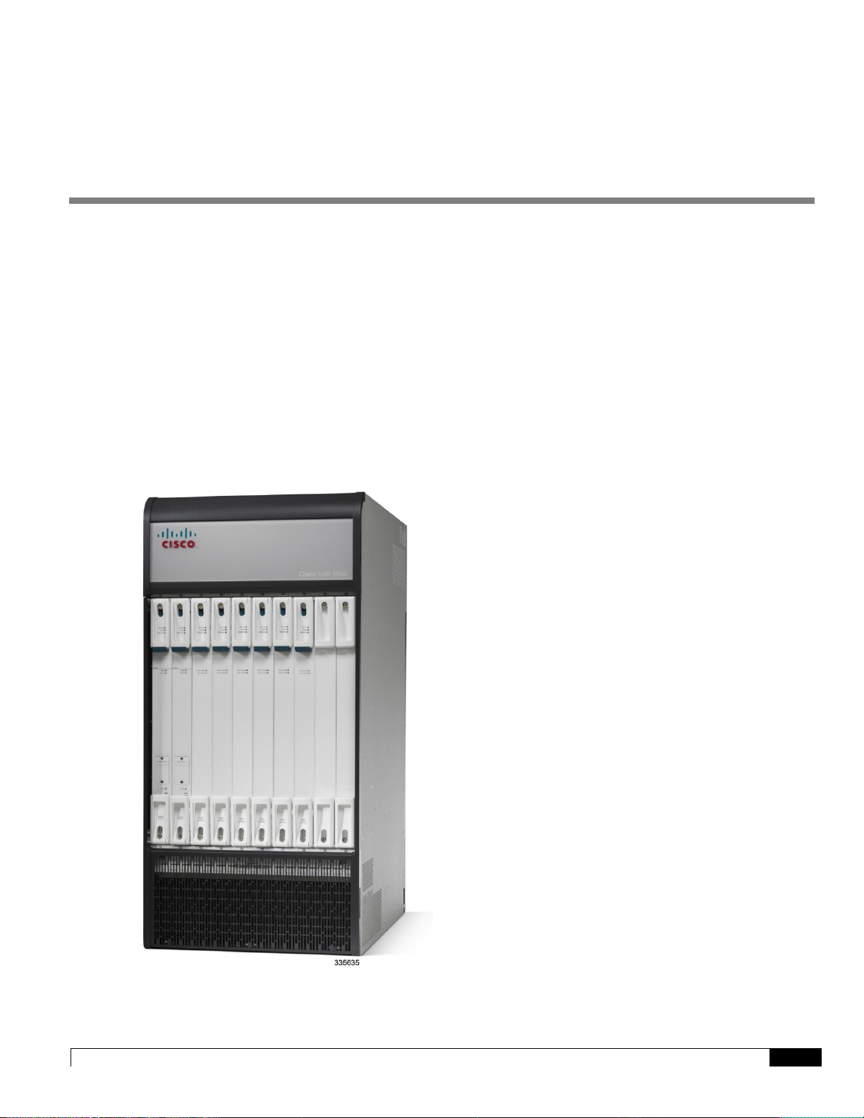
This chapter describes the hardware components that comprise the ASR 5500 chassis. The ASR 5500 is designed to
provide subscriber management services for high-capacity 4G wireless networks.
This chapter includes the following sections:
Chassis
Midplane
Card Types
LED Indicators
Figure 1. The ASR5500
Page 14

ASR 5500 Hardware Platform Overview
▀ Chassis
▄ ASR 5500 Installation Guide
14
Chassis
The ASR 5500 is a 21RU, 19" rack-mount midplane-based chassis with input/output (I/O) and processing cards in the
rear, and fabric cards in the front. Two ASR 5500 chassis fit into 42RU of rack space. However, the typical deployment
will be a single chassis per rack with other equipment in the same rack.
The rear cards are larger and used for chassis management, I/O and session processing. The smaller front cards are used
for fabric crossbars and persistent storage. There are 10 slots at the front and rear of the chassis.
The rear slots have a common midplane connector that is shared between the supported cards. This allows for different
mixes of I/O and processing capacity depending on the customer's intended use.
The chassis can be flush-mounted or mid-mounted in a rack or equipment cabinet.
Figure 2. Front and Rear Views of the ASR 5500 Chassis
Power
The chassis accepts up to eight 80-amp, -48 VDC power feeds across redundant power filter units (PFUs). The
connections are made at the top-rear of the chassis. The front-mounted PFUs incorporate separate circuit breakers for
each power feed.
Page 15
ASR 5500 Hardware Platform Overview
Chassis ▀
ASR 5500 Installation Guide ▄
15
Cooling
The ASR 5500 uses two types of fan tray units and a total of four fan trays per chassis – two front fan trays and two rear
fan trays. Air is drawn from the front and sides of the chassis and exhausted out the top rear and sides. Two fan trays are
mounted at the bottom of the chassis with another two at the top. The bottom fan trays incorporate replaceable
particulate air filters.
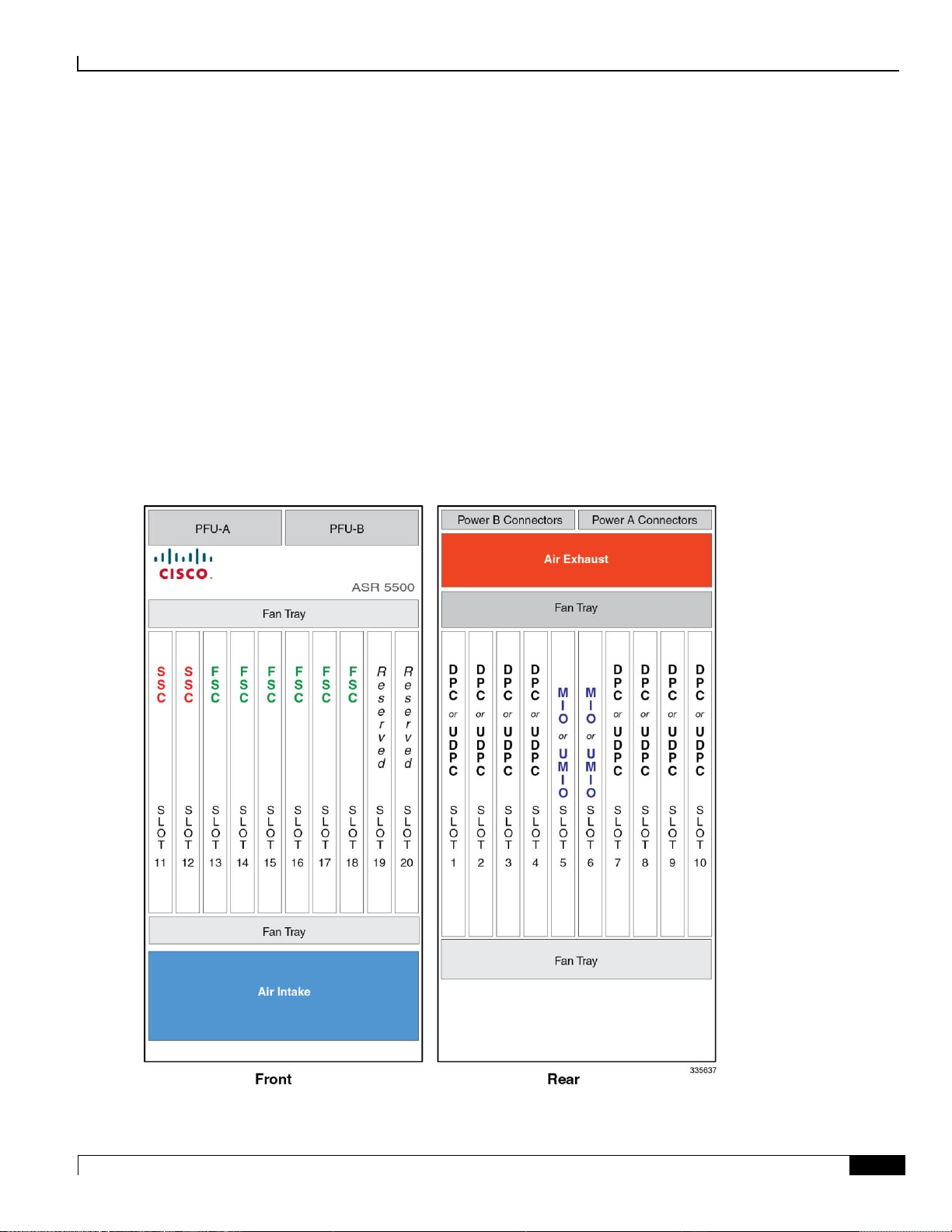
Slot Numbering
The rear slots are numbered 1 through 10 with slots 5 and 6 used for the chassis management cards. The front slots are
numbered 11 through 20. Lower slot numbers begin at the left side. There are no direct relationships between front and
rear cards.
The figure below shows the slot numbering sequence and the general layout of other components in the ASR 5500
chassis.
Figure 3. ASR 5500 Slot Numbering
Page 16

ASR 5500 Hardware Platform Overview
▀ Chassis
▄ ASR 5500 Installation Guide
16
Power Filter Units (PFUs)
Two PFUs mount at the top front of the chassis. Each PFU supports four power planes.
A total of eight -48 VDC, 80-amp power feeds are required for a full chassis. The eight feeds operate in a 4+4 redundant
configuration. In lab environments where power redundancy is not required, four 80 A lines can be used.
Cable Management System
The ASR 5500 cable management system consists of two components. The first is a tray that mounts at the rea r of the
chassis immediately below the card cage. The second is a cable management bracket that mounts to the front panel of
each Management Input/Output (MIO) or Management Input/Output Universal (UMIO) card.
Network cables are fed from either side or both sides of the tray and are then routed to the MIO/UMIO ports. The cables
are secured to the cable management brackets on the MIO/UMIOs via cable ties or hook-and-loop straps, and within the
cable management tray via hook-and-loop straps.
Page 17
ASR 5500 Hardware Platform Overview
Midplane ▀
ASR 5500 Installation Guide ▄
17
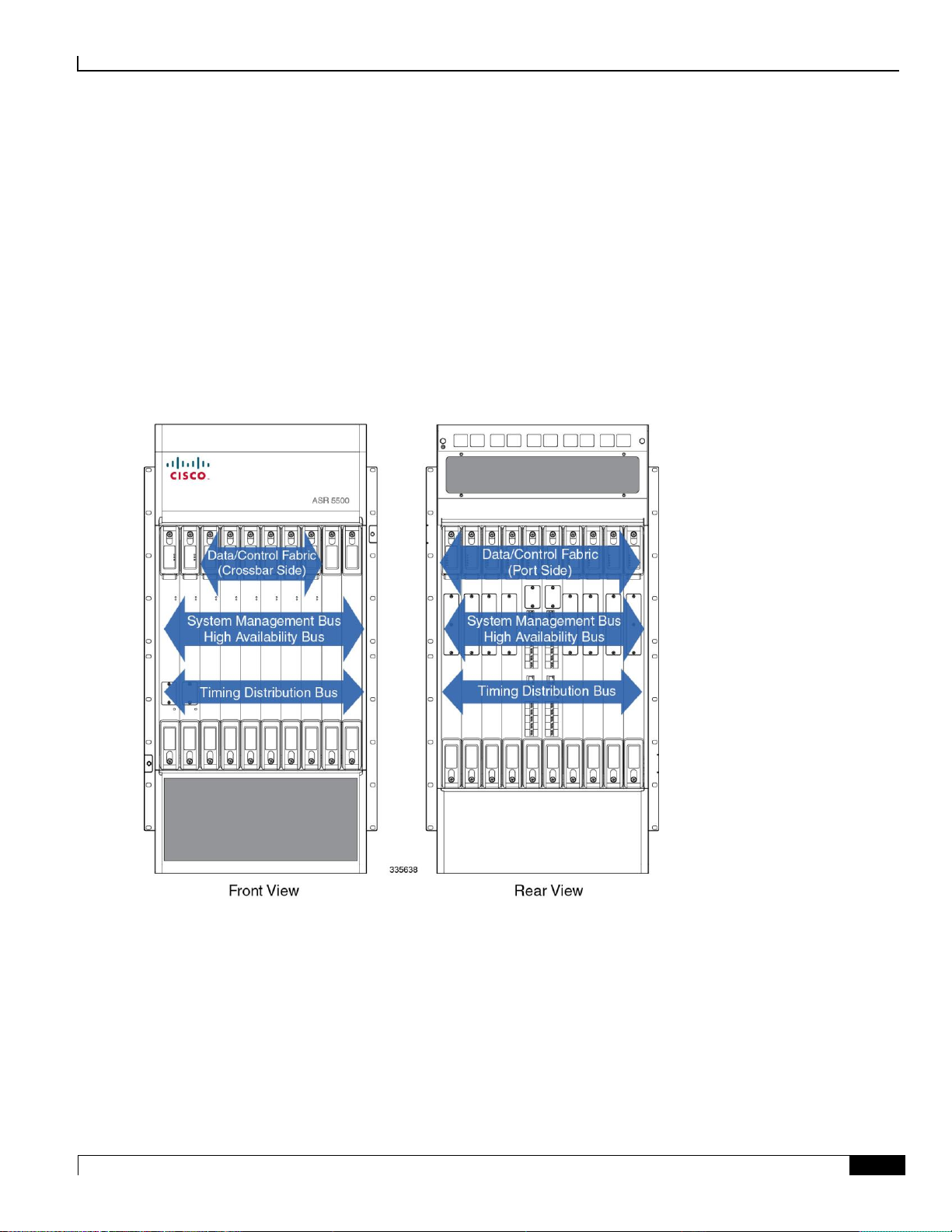
Midplane
The midplane within the ASR 5500 chassis interconnects rear input/output ports and processing cards with front fabric
cards. The larger rear cards support chassis management, input/output, and session processing. The smaller front cards
provide fabric crossbars, persistent storage and system status monitoring.
The rear slots have a common midplane connector that is shared between the supported cards. This allows for different
mixes of input/output and processing capacity depending on the customer's intended use. The two MIO or UMIO slots
(5 and 6) have additional midplane connections to perform chassis control operations, including support for a serial
Console port and dual remote management ports.
Figure 4. ASR 5500 Midplane Buses
Page 18

ASR 5500 Hardware Platform Overview
▀ Card Types
▄ ASR 5500 Installation Guide
18
Card Types
The ASR 5500 supports rear cards and front cards. Rear cards are larger and perform node management, packet
processing and I/O functions (traffic sources). Front cards determine the amount of bandwidth for the switching fabric
(crossbars), and indicate the operating and alarm status of the ASR 5500. The figure below is a simplified block diagram
showing the ASR 5500 card architecture.
Figure 5. Block Diagram of Card Architecture
Page 19
ASR 5500 Hardware Platform Overview
Card Types ▀
ASR 5500 Installation Guide ▄
19
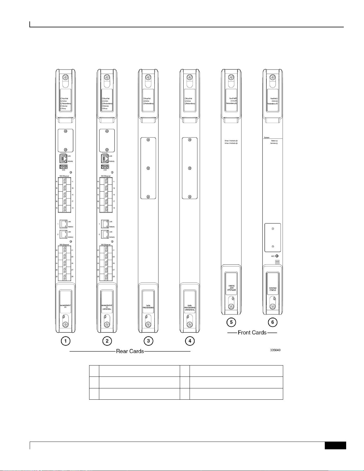
Figure 6. ASR 5500 Circuit Cards
1
Management I/O (MIO)
2
Management I/O Universal (UMIO)
3
Data Processing Card (DPC)
4
Data Processing Universal (UDPC)
5
Fabric and Storage Card (FSC)
6
System Status Card (SSC)
Page 20
ASR 5500 Hardware Platform Overview
▀ Card Types
▄ ASR 5500 Installation Guide
20
Rear Cards
The ASR 5500 supports four types of rear-mounted cards:
Management I/O Card (MIO) or Management I/O Universal Card (UMIO) [two per system]
Data Processing Card (DPC) or Data Processing Universal Card (UDPC) [up to eight per system]
The ARS 5500 supports ten rear cards, a mix of MIOs, UMIOs, DPCs and/or UDPCs. Each card is interconnected with
the others via the switching fabric.
Important: UMIO cards and UDPCs are direct replacements for MIO cards and DPCs. However, a special
Universal PID license must be purchased and installed on the chassis for each installed UMIO and UDPC. Contact your
Cisco account representative for additional information.
Management I/O
The ASR 5500 chassis supports two MIO and/or UMIO cards placed in the rear facing slots of the chassis. These cards
perform chassis management, as well as local context and non-local context external I/O operations.
Important: The MIO/UMIO cards automatically implement 1:1 port redundancy (active/standby). Ports are 1:1
redundant across slots 5 and 6. For example, port 10 on the MIO in slot 5 is redundant with port 10 on the MIO in slot 6.
Each MIO/UMIO has:
One CPU subsystem with 96 GB of RAM
Four NPU subsystems
The two 1000Base-T (1GbE) ports on MIO/UMIO cards can only be used for local context (OAM). An MIO/UMIO
includes support for:
Midplane connections for chassis control operations
SAS storage controller for FSC solid state drives (SSDs)
RS-232 serial console (RJ45) for CLI management
USB port for an external flash device
32 GB SDHC internal flash device
MIO/UMIO cards support two daughter card (DCs) for external I/O interfaces (100 Gbps aggregate per DC). The
optical ports on the daughter cards can only be used for non-local context. The currently available DC supports ten 10
GbE interfaces. The interface ports accept SFP+ SR and LR transceivers.
Important: MIO/UMIO daughter cards are not user installable or replaceable.
Important: MIO/UMIO cards are shipped with SFP+ SR or LR transceivers installed.
Page 21
ASR 5500 Hardware Platform Overview
Card Types ▀
ASR 5500 Installation Guide ▄
21
Data Processing Card
The ASR 5500 chassis supports multiple DPCs and/or UDPCs in the rear facing slots of the chassis.
The DPC/UDPC has two identical CPU subsystems with each containing:
96 GB of RAM
NPU for session data flow offload
Crypto offload engines located on a daughter card
DPC/UDPCs manage subscriber sessions and control traffic.
Front Cards
The ASR 5500 supports two types of front-mounted cards:
Fabric and Storage Card (FSC)
System Status Card (SSC)
The crossbars that comprise the switching fabric are on the FSCs. The ASR 5500 supports multiple FSCs. Each FSC
provides six physical fabric planes. When fully populated, there are 24 fabric planes in the system. A physical fabric
plane provides full-mesh connectivity between all traffic sources.
Fabric and Storage Card (FSC)
The ASR 5500 chassis supports multiple FSCs in front facing slots of the chassis.
The FSC features:
Fabric cross-bars providing in aggregate:
120 Gbps full-duplex fabric connection to each MIO/UMIO
60 Gbps full-duplex fabric connection to each DPC/UDPC
Two 2.5" serial attached SCSI (SAS), 200GB solid state drives (SSDs) with a 6 Gbps SAS connection to each
MIO/UMIO.
Every FSC adds to the available fabric bandwidth to each card. Each FSC connects to all MIO/UMIOs or DPC/UDPCs,
with a varying number of links depending on the MIO/UMIO or DPC/UDPC slot. Three FSCs provide sufficient
bandwidth while the fourth FSC supports redundancy.
Important: Although four FSCs are required for redundancy, the system can operate with three FSCs in the
presence of a fourth failed FSC. Four FSCs must be installed for normal operation.
Important: The SSDs are not field replaceable units (FRUs). If an SSD fails the FSC must be replaced.
The ASR 5500 uses an array of solid state drives (SSDs) for short-term persistent storage. The RAID 05 configuration
has each pair of drives on an FSC striped into a RAID 0 array; all the arrays are then grouped into a RAID 5 array. Each
FSC provides the storage for one quarter of the RAID 5 array. Data is striped across all four FSCs with each FSC
providing parity data for the other three FSCs. The array is managed by the master MIO/UMIO.
Page 22
ASR 5500 Hardware Platform Overview
▀ Card Types
▄ ASR 5500 Installation Guide
22
Important: A minimum of three FSCs must be online at all times for the array to operate. When an FSC is
removed, one RAID 0 array is lost with the RAID 5 array providing redundancy.
Important: Removal of an FSC while the array is degraded or rebuilding may result in data loss.
The array appears under /hd-raid and is available to all DPC/UDPCs and MIO/UMIOs.
System Status Card (SSC)
The ASR 5500 chassis supports two SSCs in front facing slots of the chassis. SSCs use dedicated slots in the left most
slots of the front side of the chassis.
The SSC card features:
Three alarm relays (Form C contacts)
Audible alarm with front panel Alarm Cutoff (ACO)
System status LEDs
Page 23
ASR 5500 Hardware Platform Overview
LED Indicators ▀
ASR 5500 Installation Guide ▄
23
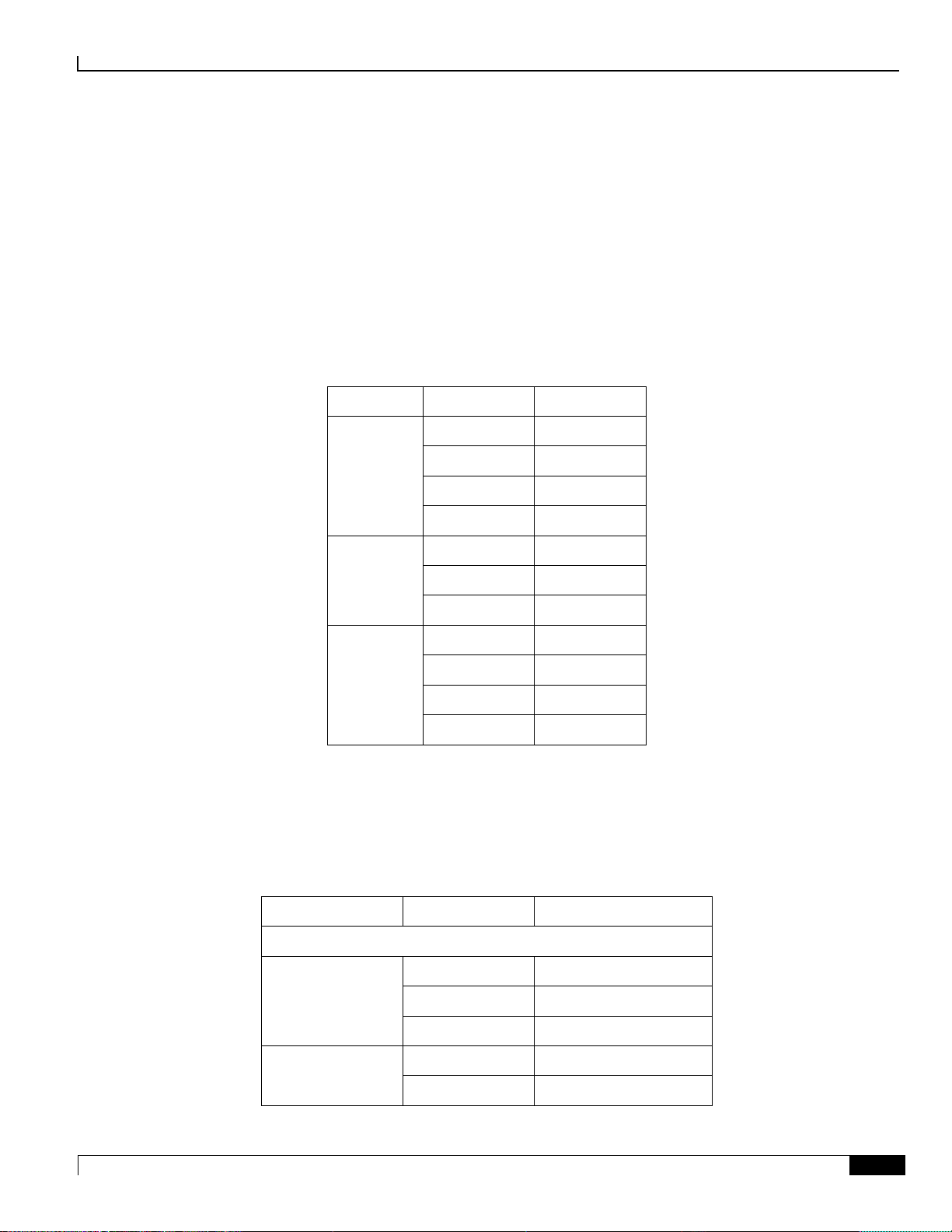
LED Indicators
Label
State
Meaning
Run/Fail
Off
Offline
Green – Blink
Transitioning
Green – Solid
Online
Red
Failure
Active
Off
Not applicable
Green – Blink
Transitioning
Green – Solid
Active
Redundancy
Off
Not applicable
Amber – Solid
Non-redundant
Amber – Blink
Transitioning
Green
Redundant
Label
State
Meaning
MIO or UMIO
Master
Off
Not applicable
Green – Blink
Transitioning
Green – Solid
Master
Busy
Off
No activity
Green
Storage activity
All ASR 5500 circuit cards incorporate light emitting diode (LED) status indicators. A base group appears on all cards.
Card-specific indicators show the status of ancillary functions.
LED Indicators Common to All Cards
Table 1. Base LED Group
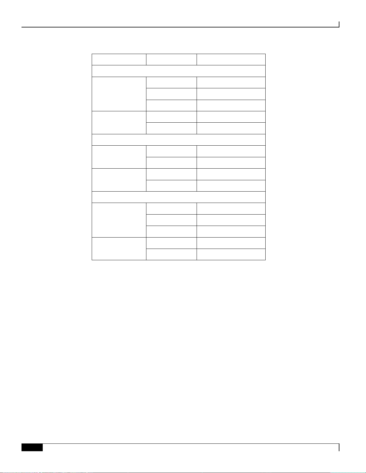
LED Indicators on Specific Cards
Table 2. Card-specific LED Group
Page 24
ASR 5500 Hardware Platform Overview
▀ LED Indicators
▄ ASR 5500 Installation Guide
24
Label
State
Meaning
Interface Ports
Link
Off
No link with network
Amber – Blink
Transitioning
Green – Solid
Linked with network
Activity
Off
No activity
Green – Blink
Data exchange
FSC
Drive 1 Activity
Off
No activity
Green
Activity
Drive 2 Activity
Off
No activity
Green
Activity
SSC
System Status
Off
System offline
Green
System online
Red
Service loss
System Service
Off
System OK
Amber
Failed component
Page 25

ASR 5500 Installation Guide ▄
25
Chapter 2
Technical Specifications
This chapter defines the technical specifications related to the installation of an ASR 5500 system.
It includes the following sections:
Physical Dimensions
Environmental Specifications
Mounting Requirements
Power Requirements
Central Office Alarm Interface
Chassis Grounding
Page 26
Technical Specifications
▀ Physical Dimensions
▄ ASR 5500 Installation Guide
26
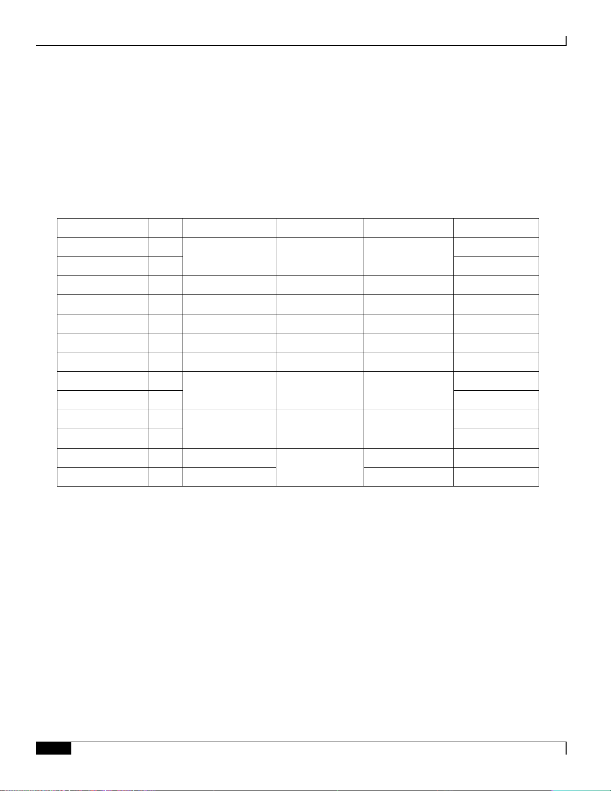
Physical Dimensions
Component
Notes
Height
Width
Depth
Weight
Chassis (empty)
1
36.75 in. (93.3 cm)
17.25 in. (43.8 cm)
27.5 in. (69.8 cm)
131 lbs (51.25 kg)
Chassis as shipped
2
226 lbs (102.5 kg)
Chassis (maximum)
3
36.75 in. (93.3 cm)
17.25 in. (43.8 cm)
32.0 in. (81.3 cm)
450 lbs (204.1 kg)
Chassis (shipping)
4, 5
50 in. (127 cm)
24 in. (61 cm)
32 in. (81.3 cm)
265 bs (120.2 kg)
Fan Tray – Front
—
1.625 in. (4.13 cm)
16.37 in. (41.6 cm)
5.625 in. (14.3 cm)
5.5 lbs (2.5 kg)
Fan Tray – Rear
—
2.125 in. (5.4 cm)
16.87 in. (42.9 cm)
18.5 in. (47 cm)
24.5 lbs (11.1 kg)
Power Filter Unit
—
3.5 in. (8.9 cm)
8.5in. (21.6 cm)
21.5 in. (54.6 cm)
15 lbs (6.8 kg)
FSC
—
19.75 in. (50.2 cm)
1.75 in. (4.44cm)
6.75in. (17.1 cm)
6 lbs (2.7 kg)
SSC
—
4.5 lbs (2 kg)
MIO or UMIO
6
21.75 in. (55.24 cm)
1.75 in. (4.44 cm)
19.5 in. (49.5 cm)
18 lbs (8.16 kg)
DPC or UDPC
—
18.5 lbs (8.4 kg)
Baffle panel – front
—
19.75 in. (50.2 cm)
1.75 in. (4.44 cm)
6.25 in. (7 cm)
1 lb (0.45 kg)
Baffle panel – rear
—
21.75in. (55.2 cm
18.625 in. 47.3 cm)
2.5 lbs (1.13 kg)
The ASR 5500 can be mounted in any standard (EIA-310-D, IEC 60297) 19-inch (482.6 mm) equipment cabinet or
telecommunications rack. The table below lists the dimensions for the chassis and each component that can be placed
within the chassis.
Table 3. ASR 5500 Physical Dimensions and Weights
Notes:
1. No PFUs or fan trays.
2. Includes four Fan Tray Units and two PFUs.
3. Depth and weight with cable management tray installed and closed, and all card slots filled.
4. Includes shipping container, accessory box, and chassis with four Fan Tray Units and two PFUs
5. Width on the pallet forks.
6. Without cable management bracket.
Page 27
Technical Specifications
Environmental Specifications ▀
ASR 5500 Installation Guide ▄
27
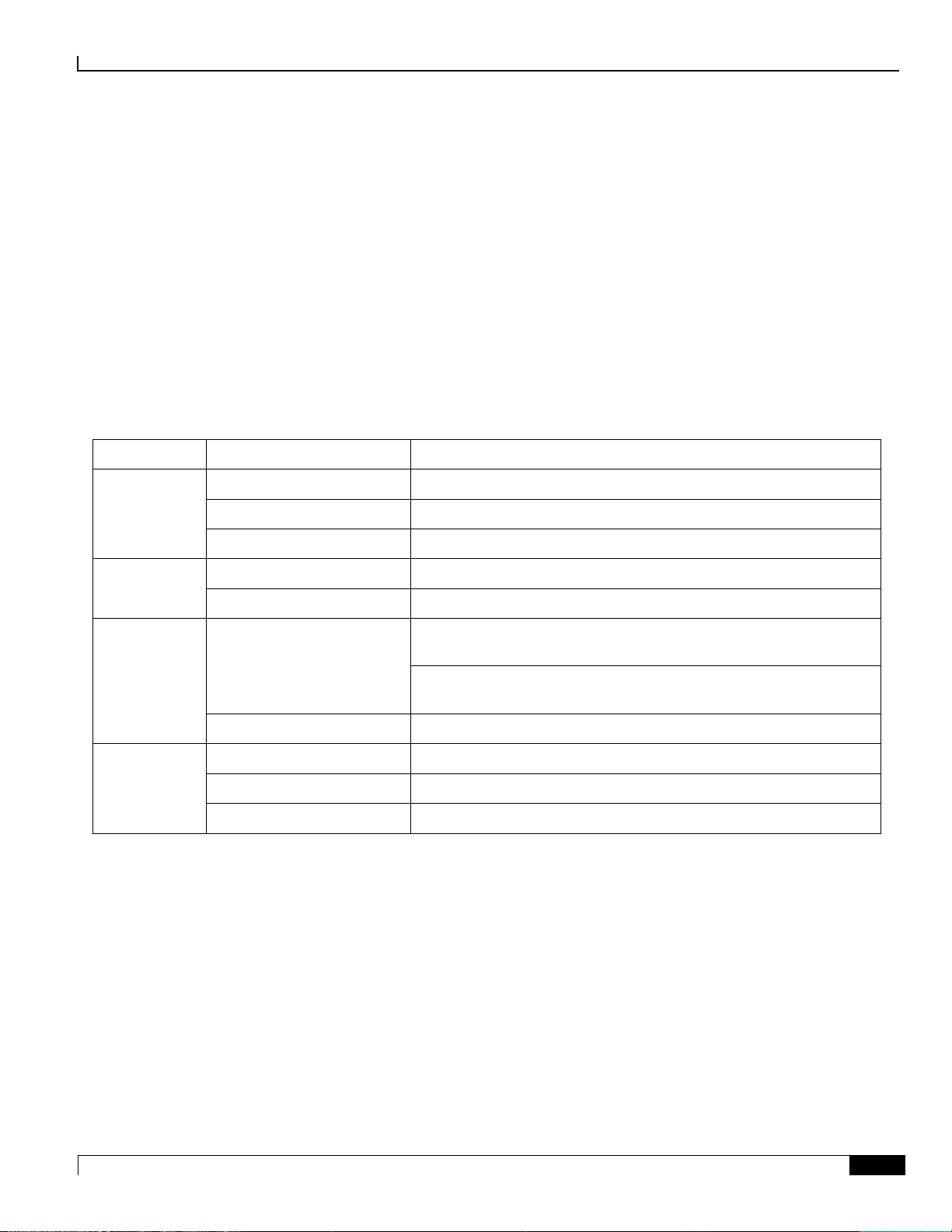
Environmental Specifications
Parameter
Subparameter
Range
Temperature
Operating
0 degrees C to +40 degrees C (32 degrees F to 104 degrees F)
Short Term
-5 degrees C to +50 degrees C (23 degrees F to 122 degrees F)
Storage
-40 degrees C to +70 degrees C (-40 degrees F to 158 degrees F)
Humidity
Operating
20 to 80 percent non-condensing
Storage
10 to 95 percent non-condensing
Altitude
Operating
197 ft. (60m) below to 5,905 ft. (1,800m) above sea level, maximum
40 degrees C (104 degrees F)
5,905 ft. (1,800m) to 13,123 ft. (4000m) above sea level, maximum
30 degrees C (86 degrees F)
Non-operating
197 ft. (60m) below to 49,212 ft. (15,000m) above sea level
Acoustic Noise
23 degrees C (73.4 degrees F)
81 dB (within GR-63 limits for unattended operation)
27 degrees C (80.6 degrees F)
81 dB (within GR-63 limits for unattended operation)
Max. Fan Speed
96 dB (as measured during GR-63 R4-97 testing)
The ASR 5500 is designed for deployment in unattended sites equipped with redundant power systems, redundant data
communications connections, environmental controls (air conditioning, fire suppression), security devices and
controlled access.
Environmental Parameters
The table below lists the environmental parameters (operating and storage) for the ASR 5500 chassis.
Table 4. Environmental Parameters
Notes:
1. Short-term refers to a period of not more than 96 consecutive hours and a total of not more than 15 days in 1
year. (This refers to a total of 360 hours in any given year, but no more than 15 occurrences during that 1-year
period.)
Page 28
Technical Specifications
▀ Environmental Specifications
▄ ASR 5500 Installation Guide
28
Environmental Standards
Type
Standard
Acoustic Noise
Telcordia GR-63 Criterion [128]
Airborne Contaminants, Indoor Levels
Telcordia GR-63 Criterion [125]
Airborne Contaminants, Outdoor Levels
Telcordia GR-63 Criteria [126, 127]
Altitude
Telcordia GR-63 Criteria [74, 76]
Earthquake Zone 4
Telcordia GR-63 Criteria [110-112, 114, 115, 117, 119]
Electromagnetic Compatibility and Electrical Safety
Telcordia Technologies GR-1089-CORE
Operational Thermal, Operating Conditions
Telcordia GR-63 Criteria [72, 73]
Operational Thermal, Short-term Conditions
Telcordia GR-63 Criteria [72, 73]
Storage Environments, and Transportation and Handling
Telcordia GR-63 Criteria [69-71, 107-109, 124]
Thermal Heat Dissipation
Telcordia GR-63 Criteria [77, 79]
Electromagnetic Compatibility and Electrical Safety
Telcordia Technologies GR-1089-CORE
Radiated Emissions (Electric Field)
FCC 47 CFR, PART 15, CLASS A
Electromagnetic Compatibility
ETSI EN 300 386 v1.4.1
Environmental Conditions and Environmental Tests for
Telecommunications Equipment
ESTI EN 300 019, ETSI EN 300 753
The ASR 5500 has been successfully tested for compliance with the environmental standards listed in table below.
Table 5. Environmental Compliance Standards
Page 29
Technical Specifications
Environmental Specifications ▀
ASR 5500 Installation Guide ▄
29
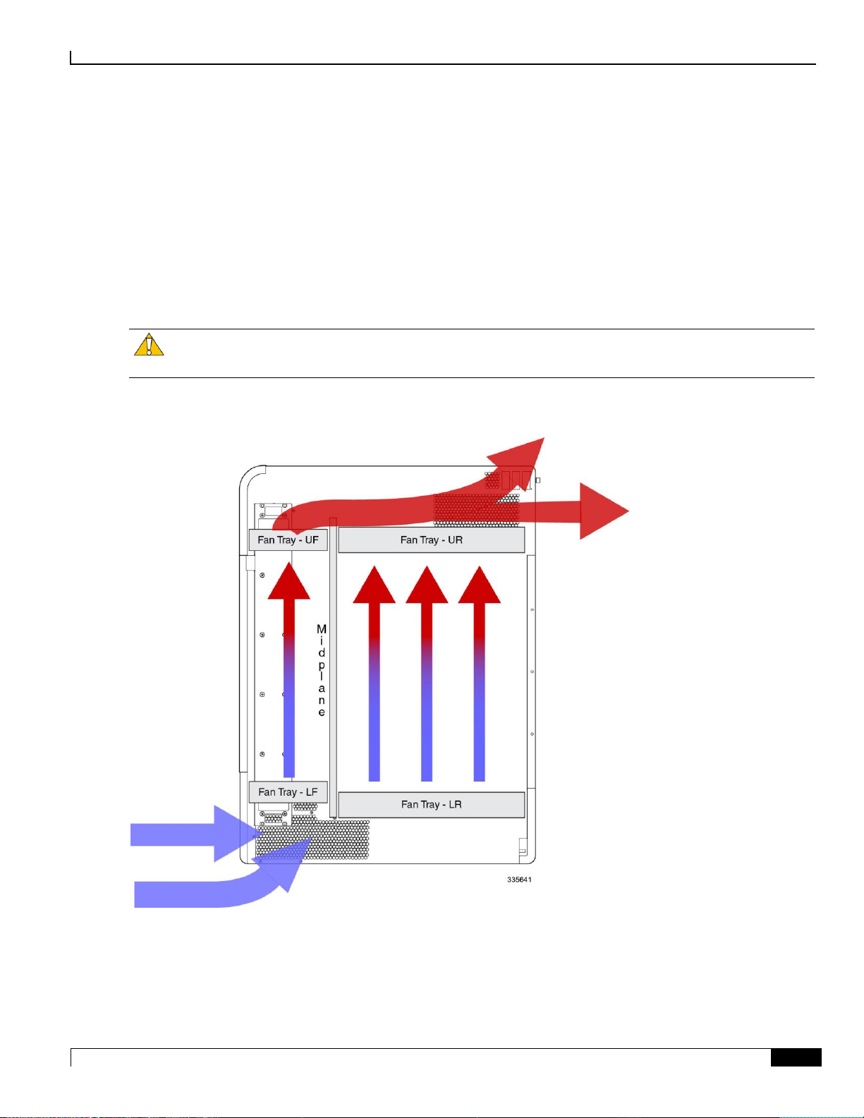
Chassis Air Flow
Air flow within the ASR 5500 complies with Telcordia recommendations to ensure vertical convection cooling of the
system.
As shown in the figure below, the lower fan trays pull ambient air inward from the front and side intake vents located
near the bottom of the chassis. The air absorbs heat from system components as it passes over them.
The upper fan trays pull heated air up through the chassis and exhaust it through the side and rear exhaust vents located
near the top rear of the chassis.
Caution: The environmental control system within the installation site must be able to maintain the ambient
environment within the limits for operating temperature and humidity.
Figure 7. Air Flow
Page 30
Technical Specifications
▀ Environmental Specifications
▄ ASR 5500 Installation Guide
30
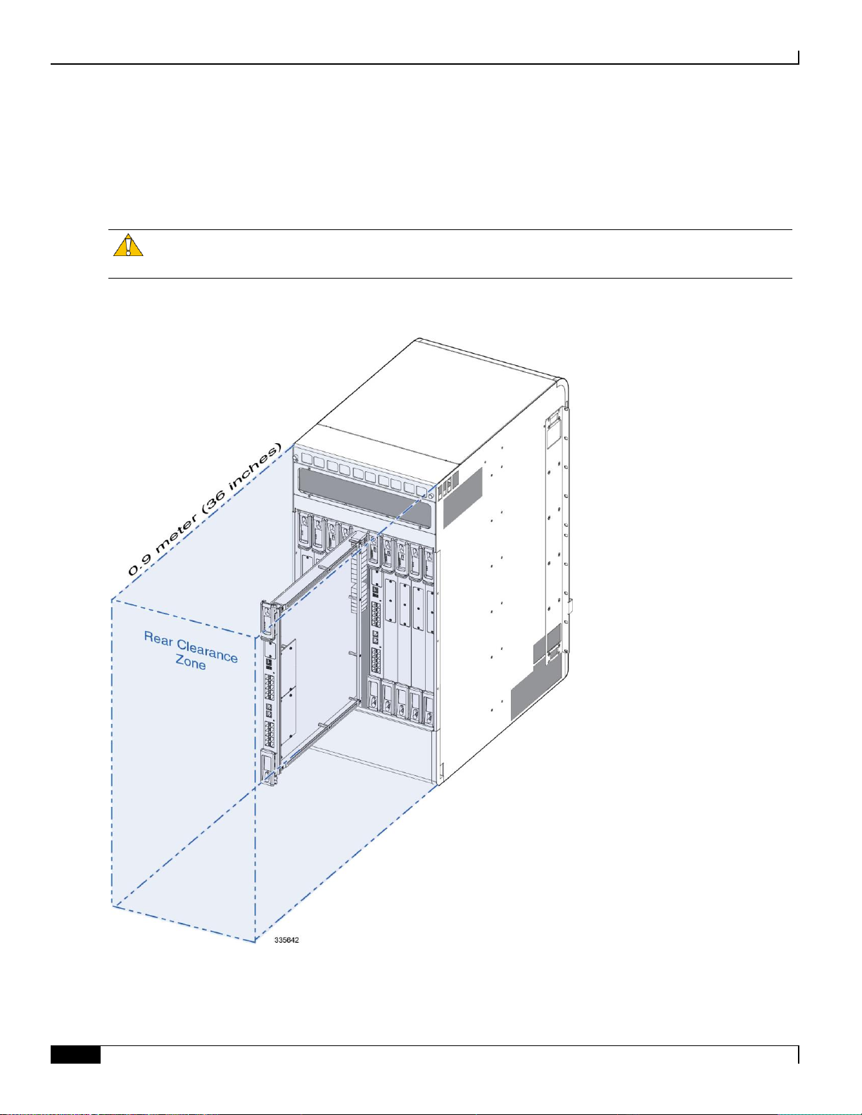
Clearance
Ensure that the equipment rack or cabinet hardware does not hinder air flow at any of the intake or exhaust vents. Allow
approximately 0.9 meter (36 inches) at the front and rear of the chassis for air flow and maintenance access.
figure below). These units are very large and require additional clearance from cable management bars, PDUs, etc.
Figure 8. Rear Clearance Zone
Caution: The rear clearance is also necessary for removing and replacing the rear cards and fan trays (see the
Page 31

Technical Specifications
Mounting Requirements ▀
ASR 5500 Installation Guide ▄
31
Mounting Requirements
Each ASR 5500 chassis occupies 21 RU (rack units) within any standard (EIA-310-D, IEC 60297) 19-inch (482.6 mm)
equipment rack or cabinet using the mounting brackets supplied with the chassis. Extension brackets (not supplied) may
be used in conjunction with the chassis mounting brackets to install the chassis in a standard 23-inch (584.2 mm)
cabinet or rack. The chassis mounting brackets may be repositioned to support flush and mid-mount installations.
The chassis footprint is approximately 19-inch (48.26 cm) wide by 26.75 in. (67.9 cm) long.
Important: This footprint does not include the rear-mounted cable management tray.
Two ASR 5500 chassis fit in 42 RU (73.5 in.) of space within an equipment rack or cabinet.
Important: Rack mounting requires the use of industry-standard equipment racks or cabinets with supplier-
recommended fasteners. The rack should be rated to accommodate the weight of one or two chassis and any auxiliary
equipment.
Page 32

Technical Specifications
▀ Power Requirements
▄ ASR 5500 Installation Guide
32
Power Requirements
Component
Parameter
Values
Chassis
Input voltage per feed circuit (nominal)
-48VDC
Input voltage per feed circuit (maximum)
-40VDC to -60VDC
Power feed circuits per PFU
4
TUV rated peak current load per feed
80 amps @ -40 VDC
Maximum power load per chassis
12,800 watts
Cards
FSC
Maximum power
100 watts
SSC
Maximum power
10 watts
MIO or UMIO
Maximum power
900 watts
DPC or UDPC
Maximum power
1,000 watts
Fan Tray Unit
Front
Maximum power
60 watts each (2 per chassis
Rear
Maximum power
840 watts each (2 per chassis)
The table below lists the power requirements for individual components of the ASR 5500 chassis.
Table 6. ASR 5500 Power Requirements
Important: The power source must be a UL/CSA listed device with a regulated output no greater that -60VDC.
Important: The DC power Battery Return (BR) or positive terminal, must be grounded at the source end (power
feed or mains power end).
Important: The DC power BR input terminal of the ASR 5500 is not connected to the equipment frame (chassis)
and is configured as DC-I in compliance with GR-1089-CORE (sec.9.8.3).
Page 33

Technical Specifications
Central Office Alarm Interface ▀
ASR 5500 Installation Guide ▄
33
Central Office Alarm Interface
The Central Office (CO) alarm interface on the SSC is a DB15 connector that supports three dry-contact relay switches.
Each of the Form C relays is rated to support a maximum switching current of 1A@30VDC.
Caution: The alarm relay contacts should never be connected to high current draw devices, such as sirens or
flashing incandescent lamps.
The three relays support both normally-open (NO) and normally-closed (NC) devices. For additional information, refer
to the SSC Alarm Cabling chapter for details.
Chassis Grounding
The ASR 5500 is suitable for installation as part of the Common Bonding Network (CBN) within a network
telecommunications facility. It is not intended for installation in an Isolated Bonding Network (IBN).
Page 34

Page 35

ASR 5500 Installation Guide ▄
35
Chapter 3
Installation Procedure Overview
This chapter briefly describes the steps and tools that are required to install the ASR 5500 chassis.
It includes the following sections:
Installation Sequence
Required Tools and Equipment
Site Prerequisites
ESD Precautions
Standards Compliance
Caution: The copper serial Console port, 1000Base-T management ports, and CO alarm interface of the
ASR 5500 are suitable for connection to intra-building or unexposed wiring or cabling only. These ports MUST NOT be
metallically connected to interfaces that connect to the outside plant (OSP) or its wiring. These interfaces are designed
for use as intra-building interfaces only (Type 2 or Type 4 ports as described in GR-1089-CORE, Issue 5) and require
isolation from the exposed OSP cabling. The addition of Primary Protectors is not sufficient protection in order to
connect these interfaces metallically to OSP wiring.
Page 36

Installation Procedure Overview
▀ Installation Sequence
▄ ASR 5500 Installation Guide
36
Installation Sequence
Installation of the ASR 5500 requires the completion of the following procedures:
1. Unpack the chassis and cards.
2. Determine which chassis mounting option to use: flush or mid-mount. Reposition the mounting brackets if
necessary.
3. Install the chassis into a standard 19-inch equipment rack or telecommunications cabinet.
4. Connect the chassis ground point to site ground.
5. Optional: Install the Chassis Management System.
6. Install SSC and FSC cards into the front of the chassis.
7. Install MIO or UMIO cards and DPCs or UDPCs into the rear of the chassis.
8. Connect data cables to the local and external ports.
9. Connect power cables to the PFU terminals at the top rear of the chassis.
10. Apply power to the chassis.
11. Verify that the system powers up successfully.
The actual sequence for completing some of the above procedures may be adapted to suit local requirements and the
availability of resources. For example, power cabling may be completed before circuit cards are installed in the chassis.
However, the chassis must always be grounded immediately after being mounted in the rack or cabinet.
Caution: For personal safety and to minimize the risk of equipment damage, power must not be applied to the
chassis until all other procedures have been completed.
Page 37

Installation Procedure Overview
Required Tools and Equipment ▀
ASR 5500 Installation Guide ▄
37
Required Tools and Equipment
This section lists the tools and equipment needed for installation.
Hand Tools
The following hand tools are required for installation of the chassis circuit cards and PFUs:
Cable/wire stripping tool – used to prepare the ends of power and ground cables for attachment to two-hole lugs.
Knife, scissors or tin snips to cut shipping straps on the chassis container.
Panduit crimping tool with 4 AWG die – used to crimp two-hole lugs on the ends of power feed cables.
Phillips #2 and #1 screwdrivers – used to tighten thumb-screws on cards, fan trays, PFUs, and mounting
brackets.
7/16-inch nut driver or ratchet and socket set – used to connect power and return, as well as chassis grounding
cable lugs to PFU terminals.
Torque wrench (rated 50 in-lb [5.65 N-m]) with 7/16-inch socket for tightening lugs to power terminals.
Grounding wrist and/or heel straps for prevention of Electro-Static Discharge (ESD).
Caution: The inappropriate use of electric or pneumatic torque drivers, or power drill/impact drivers to loosen
or tighten fasteners may result in damage to system components.
Caution: During installation, maintenance, and/or removal, wear a grounding wrist strap connected to the
ASR 5500 chassis to avoid ESD damage to the components. Failure to do so could result in damage to sensitive
electronic components and potentially void your warranty.
Equipment
The following equipment is necessary to install the chassis and verify that it is ready for configuration:
Standard 19-inch (48.26 cm) equipment rack (4-post or 2-post) or telecommunications cabinet with mounting
Multiple -48 VDC power feeds terminated at the rack/cabinet.
Voltmeter to measure input voltages at the PFU terminals.
Heat gun for installing shrink wrap tubing over power cable lugs.
Computer with a DB9 RS-232C serial port or a terminal server port that will connect to the RJ45 Console port
Pallet jack and/or chassis lift to move and position the ASR 5500 chassis. Without such mechanical assistance,
hardware. The rack/cabinet must be installed in accordance with OEM recommendations and local
practices for electrical/grounding and seismic conditions.
on the chassis management MIO or UMIO cards for accessing the Command Line Interface (CLI).
moving and positioning the chassis will require multiple craftpersons trained to safely handle heavy rackmounted units.
Page 38

Installation Procedure Overview
▀ Site Prerequisites
▄ ASR 5500 Installation Guide
38
Site Prerequisites
This section summarizes power, grounding, environment, and clearance requirements that must be met prior to
installing and operating the ASR 5500. For detailed information, refer to the Technical Specifications chapter.
Power and Grounding
Each PFU requires eight power feeds of 80A @ -48VDC (nominal). The feeds should be routed to the installation rack
from the site power supply using adequately sized conductors and circuit breakers in accordance with local electrical
codes.
The chassis must be grounded to a site ground point using the recommended conductors and lugs. The ground point
should be in close proximity to the ASR 5500 chassis to assure adequate conductivity.
Environment
The site’s heating ventilation and air conditioning (HVAC) systems must be sized to maintain the operating
temperatures and relative humidity specified in the Technical Specifications chapter. HVAC capacity requirements will
vary based on the system configuration and associated power draw, as well as the operational characteristics of other
equipment installed at the site.
Clearance
Adequate clearance must be maintained at the front and rear of the ASR 5500 chassis to assure proper air flow and
allow maintenance access for the installation, removal and replacement of components. The recommended clearance is
36 inches (92 centimeters) at the front and rear of the chassis.
Page 39

Installation Procedure Overview
ESD Precautions ▀
ASR 5500 Installation Guide ▄
39
ESD Precautions
1
Front ESD jack
2
Rear ESD jack
Electro-Static Discharge (ESD) can cause serious damage to the chassis, its sub-components and/or the cards installed in
the chassis. To prevent damage from ESD, you must take proper grounding precautions before handling the chassis or
any of its components.
The chassis and its mounting brackets are equipped with ESD jacks (see the figure below). Use the jacks in conjunction
with grounding wrist straps when handling the chassis and/or its components. The following figure shows the location
of the jacks.
Before the you can use the ESD jacks on the ASR 5500 chassis and its mounting brackets, you must first connect the
chassis to ground according to the instructions in the Chassis Installation chapter of this document.
Figure 9. Locations of ESD Jacks on the ASR 5500 Chassis
Page 40

Installation Procedure Overview
▀ Standards Compliance
▄ ASR 5500 Installation Guide
40
Standards Compliance
FCC Warning
This device complies with the limits for a Class A digital device, pursuant to Part 15 of the FCC Rules and Regulations.
Operation is subject to the following two conditions:
This device may not cause harmful interference.
This device must withstand any interference received, including interference that may cause undesired operation.
The system platform has been tested and found to comply with the limits for a Class A digital device pursuant to Part 15
of the FCC Rules and Regulations. These limits are designed to provide reasonable protection against harmful
interference when this equipment is operated in a commercial environment. This equipment generates, uses, and can
radiate radio-frequency energy and, if not installed and used in accordance with the instruction manual, may cause
harmful interference to radio and television communications. Operation of this equipment in a residential area is likely
to cause interference in which case the user will be required to correct the interference at his or her own expense.
Modifications to this product not authorized by Cisco could void the FCC approval and negate your authority to operate
the product.
Shielded cables must be used with this unit to ensure compliance with the FCC Class A limits.
ICS Notice
This Class A digital apparatus complies with Canadian ICES-003.
Cet appareil numérique de la classe A est conforme à la norme NMB-003 du Canada.
Laser Notice
The laser devices in this equipment are Class 1 devices. Class 1 laser devices are not considered to be hazardous.
Page 41

ASR 5500 Installation Guide ▄
41
Chapter 4
Chassis Installation
This chapter describes how to install the ASR 5500 chassis and its components.
Important: The ASR 5500 is suitable for installation in Network Telecommunication Facilities designed for
unattended equipment operation.
This chapter includes the following sections:
Mounting Options
Weight Considerations
Unpacking the Chassis
Reducing the Weight of the Chassis Prior to Installation
Installing the Chassis
Grounding the Chassis
Re-Installing Chassis Components
Cable Management System
Page 42

Chassis Installation
▀ Mounting Options
▄ ASR 5500 Installation Guide
42
Mounting Options
There are two options for mounting the chassis in a standard 19-inch equipment rack or telecommunications cabinet:
Flush mount: In this configuration, the flanges of the mounting brackets are flush with the front of the chassis.
This is the default configuration as shipped. This method is typically used to mount the chassis in a 4-post rack
or equipment cabinet. Refer to Flush Mount.
Mid-mount: In this configuration, the flanges of the mounting brackets are recessed from the front of the
chassis. To do this, the mounting brackets must be removed and reinstalled toward the middle of the chassis.
This method is typically used to mount the chassis in a two-post rack. Refer to Mid Mount.
Weight Considerations
The shipping weight of the chassis is approximately 226 lbs (102.5 kg). Please consider the following recommendations
before proceeding:
If available, use an equipment lift to move the chassis and position it into the rack/cabinet.
If a lift is not available, reduce the weight of the chassis by following the instructions in Reducing the Weight of
the Chassis Prior to Installation.
Remove all obstructions in the path from the delivery location to the rack/cabinet.
At least two people should perform the installation. These individuals should be physically able to lift and
control the weight of the chassis.
When lifting any heavy object, remember to bend at the knees and lift with your legs. Bending at the waist and
lifting with your back could cause personal injury.
Important: The ASR 5500 chassis is shipped with no circuit cards installed. Only the PFUs, fan trays and air
filters are installed. The circuit cards are shipped in separate cartons.
Caution: If you are mounting two chassis in a single rack, verify that the rack is rated to handle the combined,
fully loaded weight of both chassis and any ancillary equipment.
Page 43

Chassis Installation
Unpacking the Chassis ▀
ASR 5500 Installation Guide ▄
43
Unpacking the Chassis
The ASR 5500 chassis is shipped on a palletized container.
Important: The front and rear circuit cards are packaged and shipped in separate cartons.
Important: Locate the packing list for the shipment and verify that all components have been received.
Important: Safely store the shipping container and its components in case the chassis must be shipped to another
site or returned for repair.
Move the Container to the Installation Site
Before unpacking the chassis, use a pallet jack to move the container as close to the final installation site as possible.
The cardboard cap and sleeve will protect the chassis from damage when moving the container.
The chassis container measures:
Height = 50 in. (127 cm)
Width = 24 in. (61 cm)
Depth = 32 in. (81.3 cm) [width on the pallet forks]
Weight = 265 lbs (120.2 kg)
Page 44

Chassis Installation
▀ Unpacking the Chassis
▄ ASR 5500 Installation Guide
44
1
Container sleeve
2
Pallet
3
Strap
Unpack the Chassis
Caution: You should wear protective gloves and safety glasses when handling the shipping crate banding
while unpacking the system. The straps that connect the packaging material are capable of inflicting damage to your
skin or eyes if not handled properly.
Step 1 Cut the straps that secure the cap and card board sleeve to the pallet. Remove the straps from the pallet and discard.
Page 45

Chassis Installation
Unpacking the Chassis ▀
ASR 5500 Installation Guide ▄
45
1
Cardboard top
2
Outer sleeve
3
Inner Sleeve
4
Accessory box
5
Foam Cap
6
End cap
7
Pallet
8
Plastic bag (not shown)
Step 2 Remove the cardboard cap from the top of the container.
Page 46

Chassis Installation
▀ Reducing the Weight of the Chassis Prior to Installation
▄ ASR 5500 Installation Guide
46
Step 3 Lift the outer cardboard sleeve up and over the top of the chassis.
Step 4 Lift the inner cardboard sleeve up and over the top of the chassis.
Step 5 Remove the accessory box. This box contains miscellaneous hardware items and spare air filters.
Step 6 Remove the foam cap from the top of the chassis.
Step 7 Remove the bottom front and rear end caps from the base of the chassis.
Step 8 Remove the plastic bag that covers the chassis.
Step 9 If you will be removing chassis components to reduce the weight of the chassis, leave the chassis on the pallet and
proceed to Reducing the Weight of the Chassis Prior to Installation.
Step 10 Use a chassis lift or multiple craftpersons to lift or slide the chassis off the shipping pallet. Proceed to Installing the
Chassis.
Reducing the Weight of the Chassis Prior to Installation
You can reduce the weight of the chassis prior to installation by removing the upper and lower fan trays, and the PFUs.
Follow the instructions below to safely remove these components prior to installation.
Caution: During installation, maintenance and/or removal, wear a grounding wrist strap to avoid ESD damage
to the components. Connect the strap to a ground point on the rack/cabinet frame. Failure to do so could result in
damage to sensitive electronic components and potentially void your warranty.
Page 47

Chassis Installation
Reducing the Weight of the Chassis Prior to Installation ▀
ASR 5500 Installation Guide ▄
47
1
Cover panel
2
Access panel
3
Front fan tray
Removing the Fan Trays
Caution: To avoid personal injury and/or damage to the fan trays, be sure to support each fan tray's weight
from its front and rear as you slide it completely out of the chassis.
Remove the Upper Front Fan Tray
Step 1 At the front of the chassis, remove the cover panel from the top of the chassis. Firmly grasp the side edges of the panel
and pull up and away to unsnap the panel. Put the panel safely aside.
Page 48

Chassis Installation
▀ Reducing the Weight of the Chassis Prior to Installation
▄ ASR 5500 Installation Guide
48
Step 2 Use a #1 Phillips screwdriver to loosen the screws and remove the access panel from the upper-front of the chassis.
Place it safely aside.
Step 3 Loosen the two screws on the fan tray.
Step 4 Grasp the center pull on the front of the fan tray and pull. The fan tray should unseat from the midplane connector and
slide out of the chassis.
Step 5 Place the fan tray safely aside.
Remove the Lower Front Fan Tray
Step 1 Remove the cover panel from the bottom of the chassis. Firmly grasp the side edges of the panel and pull down and
away to unsnap the panel. Put the panel safely aside.
Step 2 Use a #1 Phillips screwdriver to loosen the screws and remove the access panel from the lower-front of the chassis.
Place it safely aside.
Step 3 Loosen the two screws on the fan tray.
Step 4 Grasp the center pull on the front of the fan tray and pull. The fan tray should unseat from the midplane connector and
slide out of the chassis.
Step 5 Place the fan tray safely aside.
Remove the Upper Rear Fan Tray
Step 1 At the rear of the chassis, remove the cover panel from the top of the chassis just below the vent panel. Firmly grasp the
side edges of the panel and pull up and away to unsnap the panel. Put the panel safely aside.
Step 2 Loosen the screws and remove the upper fan tray access panel from the chassis. Place it safely aside.
Step 3 Use a #1 Phillips screwdriver to loosen the two screws that secure the handle to the front of the fan tray.
Step 4 Flip up and grasp the fan tray handle and pull. The fan tray should unseat from the midplane connector and slide out of
the chassis. Support the bottom of the fan tray unit with one hand as you pull it away from the chassis.
Step 5 Place the fan tray unit safely aside.
Page 49

Chassis Installation
Reducing the Weight of the Chassis Prior to Installation ▀
ASR 5500 Installation Guide ▄
49
1
Cover panel
2
Access panel
3
Rear fan tray
Remove the Lower Rear Fan Tray
Step 1 Remove the cover panel from the bottom of the chassis. Firmly grasp the side edges of the panel and pull down and
away to unsnap the panel. Put the panel safely aside.
Step 2 Loosen the two screws and remove the access panel from the upper-front of the chassis. Place it safely aside.
Page 50

Chassis Installation
▀ Reducing the Weight of the Chassis Prior to Installation
▄ ASR 5500 Installation Guide
50
Step 3 Use a #1 Phillips screwdriver to loosen the two screws that secure the handle to the front of the fan tray.
Step 4 Flip up and grasp the fan tray handle and pull. The fan tray should unseat from the midplane connector and slide out of
the chassis. Support the bottom of the fan tray unit with one hand as you pull it away from the chassis.
Step 5 Place the fan tray unit safely aside.
Removing the PFUs
Step 1 Locate the left PFU bay (Power A) on the upper-left front of the chassis.
Step 2 Use a Phillips #2 screwdriver to loosen the four screws that secure the PFU to the chassis.
Step 3 Grasp the handle on the PFU and pull downward to free the unit from the power plane connectors. It will take
considerable force to move the handle downward and free the PFU from the power plane connectors.
Step 4 Pull the PFU toward you. The PFU should slide easily out of the chassis. Place it safely aside.
Step 5 Repeat step 2 through step 4 for the PFU located in the right bay (Power B).
Page 51

Chassis Installation
Installing the Chassis ▀
ASR 5500 Installation Guide ▄
51
Installing the Chassis
Important: If you are installing more than one chassis in an equipment rack, install the first chassis at the bottom
of the rack.
Caution: When handling or moving the chassis, lift the chassis from the bottom only. Lifting it by any other
part could damage the chassis.
Caution: During installation, maintenance and/or removal, wear a grounding wrist strap to avoid ESD damage
to the components. Connect the strap to a ground point on the rack/cabinet frame. Failure to do so could result in
damage to sensitive electronic components and potentially void your warranty.
Page 52

Chassis Installation
▀ Installing the Chassis
▄ ASR 5500 Installation Guide
52
Mounting the Chassis
Flush Mount
Step 1 Position the chassis in the equipment rack so that the flanges of the mounting brackets at the front of the chassis are
flush with the mounting rails of the equipment rack.
Step 2 Mount the chassis to the rack rails using the OEM hardware that was supplied with the equipment rack. Begin with the
two bottom holes and work your way up until all holes on each flange are secured.
Step 3 Repeat step 1 and step 2 if you are installing an additional chassis in the equipment rack/cabinet.
Step 4 If you took steps to reduce the weight of the chassis prior to installation, refer to Re-Installing Chassis Components.
Otherwise, proceed to Grounding the Chassis.
Page 53

Chassis Installation
Installing the Chassis ▀
ASR 5500 Installation Guide ▄
53
Mid Mount
Step 1 On the side of the chassis, use a Phillips #2 screwdriver to remove the twelve flathead screws that secure the mounting
bracket to the chassis.
Step 2 Place the mounting bracket over the middle set of mounting holes on the side of the chassis and secure it to the chassis
with the screws you removed in step 1.
Step 3 Repeat step 1 and step 2 and reposition the bracket on the opposite side of the chassis.
Step 4 Position the chassis in the equipment rack so that the flanges of the mounting brackets are flush with the mounting rails
of the equipment rack.
Step 5 Mount the chassis to the rack rails using the OEM hardware that was supplied with the equipment rack. Begin with the
Step 6 If you took steps to reduce the weight of the chassis prior to installation, refer to Re-Installing Chassis Components .
two bottom holes and work your way up until all holes on each flange are secured.
Otherwise, proceed to Grounding the Chassis.
Page 54

Chassis Installation
▀ Grounding the Chassis
▄ ASR 5500 Installation Guide
54
Grounding the Chassis
The chassis must be properly grounded prior to installing any chassis components or cards. The chassis and the
equipment rack/cabinet must be connected to the same ground point.
Caution: Failure to properly ground the chassis could result in personal injury and/or damage to the chassis and
its components.
There are two sets of grounding terminals located at the lower-rear of the chassis. Figure 4-8 shows the location of these
terminals and provides specifications for the appropriate lug and cable size.
Ground Cabling
Important: The ASR 5500 is suitable for installation as part of the Common Bonding Network (CBN) in a
network telecommunications facility. It is not intended for installation in an Isolated Bonding Network (IBN).
A 2-hole lug (Panduit LCD4-14A-L) is supplied for grounding the chassis. The lug must be crimped to the end of a
ground cable using Panduit crimp tool part number CT-720-1 (die color: gray, P29). The wire strip length is 7/8-inch
(22 mm),
The minimum, recommended stranded cable size is 4 AWG. the cable length to the site ground point should not exceed
70 feet (21 m) one way.
The method of connection is: chassis -> lug -> flat washer -> nut (7/16-inch).
Page 55

Chassis Installation
Grounding the Chassis ▀
ASR 5500 Installation Guide ▄
55
Figure 10. Location of Chassis Ground Terminals
1
Chassis ground point
2
Grounding cable
3
2-hole lug
4
Flat washer
5
7/16-inch Kep nut
Grounding Procedure
Step 1 Remove the rear bottom cover from the chassis. Grasp both sides of the cover and pull out and up to unsnap the cover.
Step 2 Locate the ground terminal on the lower-left corner at the rear of the chassis.
Step 3 Use a 7/16-inch nut driver or socket wrench to remove the Kep nuts and washers from each post.
Step 4 Insert the lug connected to the grounding cable over the two posts.
Step 5 Secure the lug to the ground terminals with the Kep nuts and washers you removed in step 2. The nuts should be
torqued to 50 in-lb (5.65 N-m).
Page 56

Chassis Installation
▀ Grounding the Chassis
▄ ASR 5500 Installation Guide
56
Step 6 Repeat step 2 through step 5 to connect the ground cable to the grounding posts on the lower-right corner at the rear of
the chassis.
Step 7 If you took steps to reduce the weight of the chassis prior to installation, refer to the instructions in Re-Installing
Chassis Components. Otherwise, proceed to the Card Installation chapter.
Page 57

Chassis Installation
Re-Installing Chassis Components ▀
ASR 5500 Installation Guide ▄
57
Re-Installing Chassis Components
If you removed chassis components to reduce the weight of the chassis, re-install the components by completing the
following the procedures.
Caution: During installation, maintenance, and/or removal, wear a grounding wrist strap connected to the
ASR 5500 chassis to avoid ESD damage to the components. Failure to do so could result in damage to sensitive
electronic components and potentially void your warranty.
Re-install the PFUs
Step 1 At the front of the chassis, locate the PFU bays at the top of the chassis.
Step 2 Slide a PFU into the left bay (Power A).
Step 3 Push the handle on the PFU upward to firmly seat the unit into the power plane connectors. It will take considerable
force to move the handle upward and seat the PFU into the power plane connectors.
Step 4 Use a Phillips #2 screwdriver to tighten each of the four screws on the PFU to secure it to the chassis.
Step 5 Re-install the second PFU in the right bay (Power B) by repeating step 2 through step 4.
Re-install the Front Fan Trays
Lower Front Fan Tray
Step 1 At the front of the chassis, align the fan tray within the lower chassis opening. With the unit resting on the bottom rail of
the opening, push inward until it is seated in the midplane.
Step 2 Use a #1 Phillips screwdriver to tighten the two captive screws that secure the fan tray to the chassis.
Step 3 Reinstall the lower access cover.
Upper Front Fan Tray
Step 1 Align the fan tray within the upper chassis opening. With the unit resting on the bottom rail of the opening, push inward
until it is seated in the midplane.
Step 2 Use a #1 Phillips screwdriver to tighten the two captive screws that secure the fan tray to the chassis.
Step 3 Reinstall the upper access cover.
Page 58

Chassis Installation
▀ Re-Installing Chassis Components
▄ ASR 5500 Installation Guide
58
Re-install the Rear Fan Trays
Lower Rear Fan Tray
Step 1 At the rear of the chassis, align the fan tray within the opening at the bottom rear of the chassis.
Step 2 With the unit resting on the bottom rail of the opening, slowly slide the fan tray into the chassis along the guides until it
is seated firmly in the midplane connectors.
Step 3 Reinstall the lower access cover.
Upper Rear Fan Tray
Step 1 Align the fan tray within the opening at the upper rear of the chassis.
Step 2 With the unit resting on the bottom rail of the opening, slowly slide the fan tray into the chassis along the guides until it
is seated firmly in the midplane connectors.
Step 3 Reinstall the upper access cover.
Re-install the Chassis Cover Panels
Front of Chassis
Step 1 Reinstall the top cover panel by aligning the cover over the balled posts on the fan tray access panel and above the PDF
bays. Push inwards to snap it in place.
Step 2 Reinstall the bottom cover panel by aligning the cover over the balled posts on the fan tray access panel and below the
air intake panel. Push inwards to snap it in place.
Rear of Chassis
Step 1 Reinstall the top cover panel by aligning the cover over the balled posts on the fan tray access panel. Push inwards to
snap it in place.
Step 2 Reinstall the bottom cover panel by aligning the cover over the balled posts on the fan tray access panel and below the
ground terminals. Push inwards to snap it in place.
Page 59

Chassis Installation
Cable Management System ▀
ASR 5500 Installation Guide ▄
59
Cable Management System
The ASR 5500 chassis ships with a cable management tray. This tray can be used in conjunction with cable
management brackets that mount on the MIO or UMIO cards to route and secure network cables to MIO/UMIO ports.
Important: Installation of the cable management system is optional.
Refer to the Cable Management System Installation appendix for additional information.
Page 60

Page 61

ASR 5500 Installation Guide ▄
61
Chapter 5
Card Installation
This chapter describes how to install circuit cards in the ASR 5500 chassis.
It includes the following sections:
Card Slot Assignments
Installing Cards
Baffle Cards
Save Shipping Cartons
Page 62

Card Installation
▀ Card Slot Assignments
▄ ASR 5500 Installation Guide
62
Card Slot Assignments
Slot
Card Sequence
Requirement
Rear of Chassis
1
DPC-5 or UDPC-5
Available
2
DPC-3 or UDPC-3
Required for all systems
3
DPC-1 or UDPC-1
Required for all systems
4
DPC-7 or UDPC-7
Available
5
MIO-1 or UMIO-1
Required for all systems
6
MIO-2 or UMIO-2
Required for all systems
7
DPC-8 or UDPC-8
Available
8
DPC-2 or UDPC-2
Required for all systems
9
DPC-4 or UDPC-4
Required for all systems
10
DPC-6 or UDPC-6
Available
Front of Chassis
11
SSC-2
Required for all systems
12
SSC-1
Required for all systems
13
FSC-6
Available
14
FSC-4
Required for all systems
15
FSC-2
Required for all systems
16
FSC-3
Required for all systems
17
FSC-1
Required for all systems
18
FSC-5
Available
19
Reserved
—
20
Reserved
—
The table below shows recommended card slot assignments for typical installation scenarios. The recommended card
assignments are based on the multiple power planes sourcing power to the card slots. Refer to the Power Planes section
of the Power Cabling chapter for additional information.
Following the recommendations preserves redundant operation if input power is lost to one or more of the power
circuits on the PFUs.
Table 7. ASR 5500 Chassis Card Slot Assignments
Page 63

Card Installation
Installing Cards ▀
ASR 5500 Installation Guide ▄
63
Installing Cards
The installation procedure is identical for all cards in the chassis.
Caution: During installation, maintenance, and/or removal, wear a grounding wrist strap connected to the
ASR 5500 chassis to avoid ESD damage to the components. Failure to do so could result in damage to sensitive
electronic components and potentially void your warranty.
Important: Save several of the shipping cartons and ESD protective bags for use if a card must be returned to
Cisco for fault analysis.
Important: On a chassis equipped with the cable management tray, you must lower the tray to insert rear circuit
cards. Refer to the Lowering the Cable Management Tray section in the Cable Management System Installation
appendix. The cable management tray can be installed after all rear cards have been installed.
Important: Install cable management brackets on MIO cards before inserting the card into the chassis. Refer to
the Installing the Cable Management Bracket on an MIO or UMIO Card section in the Cable Management System
Installation appendix.
Card Interlock Switch
The top and bottom handles of ASR 5500 circuit cards incorporate hooks that fit behind the upper and lower rails of the
card cage. Lifting the handles outwards ejects the card from the midplane. Pushing the handles inwards seats the card
into the midplane.
The top handle incorporates an interlock switch that signals the system that a card is seated in the slot. The blue
subhandle must be pushed fully upward to engage the interlock switch. The subhandle also locks the top handle against
the front of the card. Tightening the captive screw within the top handle secures the subhandle and circuit card to the
card cage.
Page 64

Card Installation
▀ Installing Cards
▄ ASR 5500 Installation Guide
64
Figure 11. Card Ejector Handle
1
Ejector handle
2
Ejector subhandle (interlock)
3
Captive screw
Card Installation Procedure
Step 1 Determine the type of card you are installing. The card type is identified by the label within the bottom handle of the
card.
Step 2 Determine in which chassis slot to install the card based on the information in the table at the beginning of this chapter.
Step 3 Position both handles on the circuit card to be up and away (outwards) from the front panel of the card.
Page 65

Card Installation
Installing Cards ▀
ASR 5500 Installation Guide ▄
65
1
MIO card
2
Ejector handle
3
Ejector subhandle (interlock)
Step 4 Properly support the weight of the card and align it with the upper and lower card guides of the chassis slot. Gently slide
the card into the slot until the levers touch the chassis frame.
Important: When installing cards that contain heat sinks, avoid any contact with an adjacent card. Such contact
may loosen a heat sink as the card is being slid into the chassis slot.
Caution: Never use a cable management bracket on an MIO or UMIO card to lift or insert the card into the
chassis. The bracket is not designed to support the weight of the card.
Step 5 Push both handles inward firmly until the card is seated in the chassis midplane and you cannot push the handles in any
further. Press firmly on the card's faceplate to ensure that it is fully seated. The card's front panel should be flush against
the chassis' upper and lower card mounts for the slot.
Step 6 Raise the blue subhandle under the top handle to engage interlock switch. The subhandle also locks the top handle to the
front panel.
Page 66

Card Installation
▀ Installing Cards
▄ ASR 5500 Installation Guide
66
Step 7 Use a Phillips #2 screwdriver to tighten the captive screws within the top and bottom handles to secure the card to the
chassis.
Step 8 Repeat step 1 through step 7 for every card you are installing at the rear and front of the chassis.
Page 67

Card Installation
Baffle Cards ▀
ASR 5500 Installation Guide ▄
67
Baffle Cards
Caution: To ensure proper ventilation, baffle cards must be used in any chassis slot that is not occupied by a
circuit card.
Baffle cards consist of a blank front panel mounted to a formed metal baffle. The baffle slides into the card slots and
provides a directed path for air flow. There are two types of baffle cards – front and rear.
Figure 12. Front and Rear Baffle Cards
Page 68

Card Installation
▀ Save Shipping Cartons
▄ ASR 5500 Installation Guide
68
Installing a Front Baffle Card
Step 1 Flip both ejector handles outward from the front of the card.
Step 2 Align the baffle card within an unused chassis slot.
Step 3 Slide the card into the slot until its front panel is flush with the upper and lower card rails.
Step 4 Push the ejector handles inward until they are flush with the front of the card.
Step 5 Use a Phillips #2 screwdriver to tighten the captive screws within the ejector handles on the top and bottom of the card
to secure it to the chassis.
Step 6 Repeat step 1 through step 5 for any additional unused chassis slots.
Installing a Rear Baffle Card
Step 1 Align the baffle card within an unused chassis slot.
Step 2 Slide the card into the slot until its front panel is flush with the upper and lower card rails.
Step 3 Use a Phillips #2 screwdriver to tighten the captive screws at the top and bottom of the baffle card to secure it to the
chassis.
Step 4 Repeat step 1 through step 3 for any additional unused chassis slots.
Save Shipping Cartons
Save several of the shipping cartons and protective ESD bags in which the circuit cards were packaged. Use the cartons
to package a circuit card for shipment back to Cisco for failure analysis and replacement. For additional information,
refer to the Returning Failed Components in the Replacing Components chapter, and the RMA Shipping Procedures
appendix.
Page 69

ASR 5500 Installation Guide ▄
69
Chapter 6
MIO Port Cabling
This chapter describes how to cable the interface ports on Management I/O (MIO) or Management I/O Universal
(UMIO) cards.
It includes the following sections:
Interface Ports
Cable Management System
Console Port
Ethernet Management Ports
10 GbE Optical Daughter Card Ports
Fiber Optical Connections
Page 70

MIO Port Cabling
▀ Interface Ports
▄ ASR 5500 Installation Guide
70
Interface Ports
The interface ports are selectively enabled based on their functions in the system – management versus nonmanagement.
Card Ports
MIO or UMIO cards in slot 5 and slot 6 of the ASR 5500 chassis support the following twisted-pair copper interface
ports:
one serial Console port (RJ45)
two 1 Gigabit Ethernet ports (RJ45)
Daughter Card Ports
MIO or UMIO daughter cards support ten 10 Gigabit Ethernet ports each. The 10 GbE ports connect to other network
devices via fiber optic cables that terminate on SFP+ transceivers.
Cable Management System
If you have equipped your ASR 5500 chassis and MIO or UMIO cards with the Cable Management System, refer to the
Routing and Securing Network Cables section of the Cable Management System Installation appendix for additional
information.
Page 71

MIO Port Cabling
Cable Management System ▀
ASR 5500 Installation Guide ▄
71
Figure 13. MIO or UMIO Ports
1
Console port
2
USB port
3
10 GbE ports, DC-1
4
10 GbE ports, DC-2
5
1 GbE ports (1000Base-T)
Page 72

MIO Port Cabling
▀ Console Port
▄ ASR 5500 Installation Guide
72
Console Port
Pin
Signal Description
Signal Type
Pinout
1
Not connected
— 2
Not connected
— 3 Receive Data (RX)
Input
4
Signal Ground (SGND)
Not applicable
5
Not connected
— 6 Transmit Data (TX)
Output
7
Not connected
— 8 Not connected
—
The Console port (logical port 3) is an RJ45 RS-232 interface on an MIO or UMIO card that provides access to the
command line interface (CLI). The interface communicates at 9600 to 115200 bps; the default is 115,200 bps.
Important: A connection to the Console port is required if you wish to view boot messages whenever the
ASR 5500 chassis is powered up or rebooted. Only the Console port on the Master MIO or UMIO supports logs and
CLI sessions. The Console port on the Standby MIO or UMIO is inactive.
RJ45 Port Pinouts
Table 8. Console Port RJ45 Serial Pinout
Important: Hardware flow control is not supported and must be disabled on the connected equipment.
Page 73

MIO Port Cabling
Console Port ▀
ASR 5500 Installation Guide ▄
73
RJ45 to DB9 Adapter
Signal Description
Signal type
RJ45 Pin
DB9 Pin
Not connected
— 1 7
Not connected
— 2 4
Receive Data (RX)
Input
3 3 Signal Ground (SGND)
Not applicable
4 5 Not connected
— 5 8
Transmit Data (TX)
Output
6 2 Not connected
— 7 1
Not connected
— 8 6
An RJ45-to-RJ45 serial cable and an RJ45-to-DB9 adapter are supplied with each MIO or UMIO. The DB9 adapter is
female. If you use the cable and adapter together, refer to the following figure and table for the cable pinout.
Table 9. Console RJ45 to DB9Adapter Pinouts
Connect Console Port to Workstation
You can connect the Console port to a workstation with a serial port running a communications application, such as
Minicom for Linux® or HyperTerminal® for Windows.
To connect a workstation to the Console port, do the following:
Step 1 Plug one end of an RJ45 cable to the port labeled Console on the MIO or UMIO.
Step 2 Plug the other end of the RJ45 cable into the DB9 adapter.
Step 3 Connect the DB9 end of the adapter into the serial port on the workstation.
Step 4 Configure the communications application on the workstation to support the following:
Baud Rate = 115200 bps
Data Bits = 8
Parity = None
Stop Bits = 1
Flow Control = None
Page 74

MIO Port Cabling
▀ Console Port
▄ ASR 5500 Installation Guide
74
Connect Console Port to Terminal Server
You can connect the terminal server to a serial port on a terminal server.
Important: The Console port does not support flow control signaling required by some types of terminal servers.
Flow control must be disabled on the connected equipment.
To connect a terminal server to the Console port, do the following:
Step 1 Plug one end of an RJ45 cable to the port labeled Console on the MIO or UMIO.
Step 2 Plug the other end of the RJ45 cable into a port on the terminal server.
Step 3 Configure the communications protocol on the terminal server port to support the following:
Baud Rate = 115200 bps
Data Bits = 8
Parity = None
Stop Bits = 1
Flow Control = None
Important: For additional information on connecting the Console port to Cisco servers equipped with
asynchronous interface modules, refer to the Console Port to Cisco Server Cabling appendix.
Page 75

MIO Port Cabling
Ethernet Management Ports ▀
ASR 5500 Installation Guide ▄
75
Ethernet Management Ports
Pin
100Base-T 100Mbps Cat5
1000Base-T 1Gbps Cat5+
Pinout
1
TX+
BI DA+
2
TX-
BI DA-
3
RX+
BI DB+
4 — BI DC+
5 — BI DC-
6
RX-
BI DB-
7 — BI DD+
8 — BI DD-
MIOs or UMIOs support two autosensing RJ45 10/100/1000Base-T (IEEE 802.3ab) Ethernet, twisted-pair copper
interfaces (logical Ports 1 and 2) for out-of-band system management access to the CLI.
Important: To comply with GR-1089 intra-building, lightning-immunity requirements and FCC Radiated
Emissions Criteria, you must use shielded-twisted pair (STP) cable and ensure that it is properly terminated at both
ends.
Caution: The 1000Base-T management ports are suitable for connection to intra-building or unexposed wiring
or cabling only. These intra-building ports MUST NOT be metallically connected to interfaces that connect to the
outside plant (OSP) or its wiring. These interfaces are designed for use as intra-building interfaces only (Type 2 or Type
4 ports as described in GR-1089-CORE, Issue 5) and require isolation from the exposed OSP cabling. The addition of
Primary Protectors is not sufficient protection in order to connect these interfaces metallically to OSP wiring.
The ports support MDI and MDI-X connectors. Ethernet ports normally use MDI connectors and Ethernet ports on a
hub normally use MDI-X connectors.
An Ethernet straight-through cable is used to connect an MDI to an MDI-X port. A cross-over cable is used to connect
an MDI to an MDI port, or an MDI-X to an MDI-X port.
RJ45 Port Pinouts
Table 10. 1000Base-T RJ45 Ethernet Pinouts
Page 76

MIO Port Cabling
▀ Ethernet Management Ports
▄ ASR 5500 Installation Guide
76
Port Status LEDs
Each of these interfaces is equipped with two status LEDs:
Link: This green LED shows whether or not the line card is connected to the network. The LED is illuminated
when the card is connected.
Activity: This green LED shows when data is transmitted or received. The LED is illuminated when data is
passing through the interface.
Connect 1000Base-T Interface to Network Device
Important: To facilitate maintenance of the network cabling, the Cat-5 cables should be labeled with terminating
destinations.
Step 1 Insert one end of the Cat-5 cable into the top MGMT connector (Port 1).
Step 2 Attach the other end of the Cat-5 cable to the appropriate network interface.
Step 3 Repeat Steps 1 and 2 to connect the bottom MGMT connector (Port 2).
Page 77

MIO Port Cabling
10 GbE Optical Daughter Card Ports ▀
ASR 5500 Installation Guide ▄
77
SFP+ Transceiver Type
Parameter
Value
10GBase-SR
Maximum transmit level
-1.0dBm
Minimum transmit level
-7.3dBm
Maximum receive level
-1.0 dBm (saturation average power)
Minimum receive level
-11.1 (sensitivity average power)
10GBase-LR
Maximum transmit level
0.5 dBm
Minimum transmit level
-8.2 dBm
Maximum receive level
0.5 dBm (saturation average power)
Minimum receive level
-12.6 (sensitivity average power)
10 GbE Optical Daughter Card Ports
Caution: The 10 Gigabit Ethernet ports on the daughter cards are only certified to work with SFP+ transceivers
tested and approved by Cisco. MIO and UMIO cards ship with SFP+ transceivers installed.
The 10 Gigabit Ethernet ports accept the following fiber optic to electrical signal Small Form-Factor Pluggable (SFP+)
transceiver types:
10GBase-SR – connects the port to a multimode fiber optic cable over relatively short distances (30.80 meters).
10GBase-LR – connects the port to a single-mode fiber optic cable over a maximum distance of 10km.
The table below lists the signaling parameters supported for the above transceiver types.
Table 11. SFP+ Transceiver Parameters
Page 78

MIO Port Cabling
▀ Fiber Optical Connections
▄ ASR 5500 Installation Guide
78
Fiber Optical Connections
Caution: The SFP+ transceiver modules are static sensitive devices. Always use an ESD wrist strap or similar
individual grounding device when coming into contact with SFP+ modules.
Caution: Before connecting fiber optic cables, press each module into the slot firmly with your thumb to firmly
reseat them.
Removing Dust Plugs
Before removing the dust plugs and making any optical connections, observe the following guidelines:
Always keep the protective dust plugs on the unplugged fiber-optic cable connectors and the transceiver optical
bores until you are ready to make a connection.
Always inspect and clean the LC connector end-faces just before making any connections.
Always grasp the LC connector housing to plug or unplug a fiber-optic cable.
Important: To facilitate maintenance of the network cabling, all fiber optic cables should be labeled with
terminating destinations.
Connecting Fiber Optic Cables
Step 1 Remove the dust plug from the network interface LC connector of the SFP+ module. Save the dust plug for future use.
Step 2 Inspect and clean the LC connector’s fiber-optic end-faces.
Step 3 Insert the duplex LC/PC connector on the network cable into the duplex port on the module.
Step 4 Attach the other end of the network fiber-optic cable to the network device that you want to connect.
Step 5 Repeat Step 1 through Step 4 for the remaining ports on the daughter card.
Step 6 Repeat Step 1 through Step 4 for ports on the second DC.
Page 79

ASR 5500 Installation Guide ▄
79
Chapter 7
SSC Alarm Cabling
This chapter describes how to cable the alarm contacts on the System Status Card (SSC).
It includes the following sections:
CO Alarm Interface
Alarm Cutoff (ACO)
Alarm Connector Pinout
Electrical Characteristics
CO Alarm Wiring Example
Caution: The CO alarm interface of the SSC is suitable for connection to intra-building or unexposed wiring or
cabling only. This interface MUST NOT be metallically connected to interfaces that connect to the outside plant (OSP)
or its wiring. This interface is designed for use as an intra-building interface only (Type 2 or Type 4 ports as described
in GR-1089-CORE, Issue 5) and requires isolation from the exposed OSP cabling. The addition of Primary Protectors is
not sufficient protection in order to connect these interfaces metallically to OSP wiring.
Page 80

SSC Alarm Cabling
▀ CO Alarm Interface
▄ ASR 5500 Installation Guide
80
CO Alarm Interface
The Central Office (CO) Alarm interface on the SSC is a DB15 female connector that supports three low voltage,
normally-closed/normally-open dry-contact relays (see Figure 7-1). These Form C relays interface with an CO alarm
monitor panel to trigger external audio and/or visual indicators.
Three alarm levels are supported by the relays:
Minor Alarm – This alarm is triggered when a high temperature is detected on a card, causing the fan tray to
switch the fans to high speed.
Major Alarm – This alarm is triggered when there is a:
Hardware failure that causes the card to be placed in an off-line state
PFU failure or removal from the chassis
Failure of one or more fans on any of the upper or lower fan tray units
Fan tray failure or any fan tray unit is removed from the chassis
Critical Alarm – This alarm is triggered when a degradation in service is detected. For example, if the system is
supporting a large number of subscribers and DPCs are removed, the amount of available CPU and memory
resources available for use are reduced.
Page 81

SSC Alarm Cabling
Alarm Cutoff (ACO) ▀
ASR 5500 Installation Guide ▄
81
Alarm Cutoff (ACO)
1
Connector cover plate
2
CO alarm interface (DB15)
3
Alarm Cutoff (ACO) switch
4
Audible alarm
The front panel of the SSC includes an audible system alarm and an Alarm Cutoff (ACO) switch. Press and release this
switch to reset the system alarm speaker.
Figure 14. SSC CO Alarm Interface
Page 82

SSC Alarm Cabling
▀ Alarm Connector Pinout
▄ ASR 5500 Installation Guide
82
Alarm Connector Pinout
Pin
Alarm Level
Signal
1
Minor
Normally Open
2
Normally Closed
3 — Not connected
4
Major
Normally Open
5
Normally Closed
6 — Not connected
7
Critical
Normally Open
8
Normally Closed
9
Minor
Minor, Common
10 — Not connected
11 — Not connected
12
Major
Major, Common
13 — Not connected
14 — Not connected
15
Critical
Critical, Common
The CO alarm connector pinout is provided in the table below.
Use a Phillips #1 screwdriver to remove the two screws that secure the cover plate over the alarm connector.
Table 12. DB15S CO Alarm Connector Pinout
Electrical Characteristics
Each of the three dry-contact, Form C relay switches is rated to support a maximum switching current of 1A@30VDC.
directly to the EO alarm connector.
Caution: Never connect a high voltage/high current device such as an audible alarm/siren or incandescent lamp
Page 83

SSC Alarm Cabling
CO Alarm Wiring Example ▀
ASR 5500 Installation Guide ▄
83
CO Alarm Wiring Example
The figure below depicts how the three dry-contact relay contacts can each control up to two alarming devices. In this
example the SSC CO alarm interface is connected to a CO Alarm Panel, where green LEDs are wired to indicate normal
operation, and red LEDs are wired to indicate alarm conditions.
With all relays de-energized, the green LEDs are illuminated. If an alarm relay is energized, its NO (normally open)
contact closes; the green LED is extinguished and the red LED is illuminated.
Figure 15. CO Alarm Interface Schematic
Page 84

Page 85

ASR 5500 Installation Guide ▄
85
Chapter 8
Power Cabling
This chapter describes how to connect -48 VDC power feeds to the Power Filter Units (PFUs) on the ASR 5500 chassis.
It includes the following sections:
Power Considerations
Internal Power Planes
Power Cable Requirements
Connect Power Feeds to the PFUs
Important: The -48 VDC Battery Return (BR) input terminals to the PFUs are not connected to the equipment
frame (chassis) are treated as Isolated DC returns (DC-I) in compliance with GR-1089-CORE (sec.9.8.3).
Page 86

Power Cabling
▀ Power Considerations
▄ ASR 5500 Installation Guide
86
Power Considerations
Each chassis supports up to eight -48 VDC, 80-amp power feeds, four per PFU. Table 8-1 lists the power load factors
that should be considered for this installation site. Each feed consists of a supply and return cable.
Important: The power source must be a UL/CSA listed device with a regulated output no greater that -60VDC.
Typically, the DC power feeds are fed from a power distribution frame (PDF) to a power distribution panel (PDP) at the
rack.
Important: The DC power Battery Return (BR) or positive terminal, must be grounded at the source end (power
feed or mains power end).
Important: Minimum 4 AWG multiple strand, high-flex cable is recommended for final connections from the
PDP to the PFUs.
Each feed connects to supply and return terminals on the rear of the PFUs using two-hole lugs crimped to the end of
each cable. The feed cables are routed through openings in each side of the chassis. The input terminals are wired
through EMI filters to the ASR 5500 backplane.
The circuit breakers at the power distribution panel must disconnect the supply line of each -48VDC feed. However, it is
recommended that the circuit breakers at the power distribution panel simultaneously disconnect both poles (supply and
return) for each -48 VDC feed to completely isolate the ASR 5500 from the power source.
To maintain power redundancy, separate –48 VDC supply circuits should be used to feed each DC power input on both
PFUs.
Caution: Set the circuit breakers on the distribution panel to the OFF position before making the power
connections at the PFUs.
Each power input cable must be terminated with a supplied Panduit LCD4-14AF-L 2-hole, 90-degree lug using the
appropriate crimping tool and die.
The following alternate lug types (not supplied with the chassis) are also approved for use on the power feeds:
Panduit LCC4-14AF-L, 4 AWG, 2-hole, 90-degree long barrel lug
Burndy YAZ2C2TC1490, 2 AWG, 2-hole, 90-degree long barrel lug
If a DC power input should fail, the operating supply circuits continue to power the ASR 5500.
Page 87

Power Cabling
Internal Power Planes ▀
ASR 5500 Installation Guide ▄
87
Internal Power Planes
Card Type
Slot
Plane 1
Plane 2
Plane 3
Plane 4
Rear Cards
DPC or UDPC
1 — — — Yes
DPC or UDPC
2 — — — Yes
DPC or UDPC
3 — — — Yes
DPC or UDPC
4 — Yes — —
MIO or UMIO
5 — Yes — —
MIO or UMIO
6 — —
Yes — DPC or UDPC
7 — —
Yes — DPC or UDPC
8
Yes — — — DPC or UDPC
9
Yes — — — DPC or UDPC
10
Yes — —
—
Front Cards
SSC
11 — Yes — —
SSC
12 — Yes — —
FSC
13
Yes — — — FSC
14 — —
Yes
—
FSC
15 — —
Yes — FSC
16 — Yes — —
FSC
17 — Yes — —
FSC
18 — — — Yes
Reserved
19 — —
Yes — Reserved
20 — —
Yes
—
Four inputs are labeled A1 through A4 and the other inputs are labeled B1 through B4. A1 is redundant for B1 and so
on. The inputs correspond to the four power planes that supply power to various chassis components as shown in the
table and figure below.
The SSC monitors all eight feeds for outages.
Chassis Power Card Slot Allocations
Table 13. Chassis Power Planes
Page 88

Power Cabling
▀ Internal Power Planes
▄ ASR 5500 Installation Guide
88
Card Type
Slot
Plane 1
Plane 2
Plane 3
Plane 4
Fan Trays
Upper
Top — —
Yes — Lower
Bottom
—
Yes — —
Figure 16. PFU Redundant Power Planes
Page 89

Power Cabling
Internal Power Planes ▀
ASR 5500 Installation Guide ▄
89
Power Feed Connections
The figure below shows a recommended method for connecting -48 VDC power feeds from the power distribution
frame (PDF) through a power distribution panel (PDP) to the power filter units (PFUs) on the ASR 5500 chassis.
This method preserves electrical redundancy from the PDF to the PFUs.
Figure 17. Power Feeds to the ASR 5500 Chassis
Page 90

Power Cabling
▀ Power Cable Requirements
▄ ASR 5500 Installation Guide
90
Power Cable Requirements
Sizing Power Cables
The following guidelines should be adhered to when sizing cable gauges for connecting the PFUs to a rack-mounted
power distribution panel.
Each conductor between the PDF and PDP should be calculated assuming a 0.3 volt drop from the PDF to the
panel.
Each cable between the PDP and ASR 5500 PFUs should be calculated a 0.3 volt drop from the panel to the
chassis. This is a total voltage drop of 0.6 volts.
Use high-flex, multiple-strand cable (minimum 4 AWG) between the power distribution panel and the chassis.
Terminating Power Cables
Each cable should be terminated with a 90 degree, 2-hole lug (supplied). Each feed consists of a supply (-48VDC) and
return (RTN) cable. The feed cables terminate at the rear of each PFU on 0.25-inch posts spaced 0.63-inch on center.
Cable Routing
All feed cables must be routed through the openings at the upper rear sides of the chassis.
Method of Connection
The method of connection at each PFU terminal is: flat washer, lug, lock washer and nut (7/16-inch). The nut(s) must be
torqued to 50 in-lb. (5.65 N-m).
Insulate Lugs
Use heat shrink tubing or non-conductive tape to insulate much of the exposed metal on the lug without interfering with
the attachment point.
Crimp Lugs on Cables
Use the Panduit® lugs supplied with the chassis (LCD4-14AF-L). The lug must be crimped to the end of a ground cable
using Panduit crimp tool part number CT-720-1 (die color: gray, P29). The wire strip length is 7/8-inch (22 mm),
Follow the OEM recommendations for preparing and crimping the lugs on the ends of each feed cable.
Label All Cable
Label the supply and return cables going to each terminal on the rear of the PFUs. Include the terminal number (A-1 to
A4, B1 to B4) and power distribution panel circuit number. This will facilitate troubleshooting, as well as removal and
replacement of a failed PFU.
Page 91

Power Cabling
Connect Power Feeds to the PFUs ▀
ASR 5500 Installation Guide ▄
91
1
Handle
2
Circuit breaker
3
Blue LED
Connect Power Feeds to the PFUs
Caution: To avoid personal injury or possible equipment damage, ensure that the circuit breakers for all
ASR 5500 chassis feeds from the power distribution panel are all set to OFF before attempting to attach power cables to
the PFU(s).
Caution: Verify that all circuit breakers on the front panels of both PFUs (four per PFU) are set to OFF before
attaching power feed cables to the PFUs (see figure below). The breakers must remain OFF until the chassis is to be
powered up.
Figure 18. PFU Front Panel
Important: The eight power terminals on the back of each PFU are shipped with nuts and washers attached.
Step 1 Remove the plastic power input cover from the top-rear of the ASR 5500 chassis. Use a Phillips #2 head screw driver to
loosen the two captive screws securing the cover to the chassis. Removing this cover exposes the power feed terminals
at the rear of the PFUs.
Page 92

Power Cabling
▀ Connect Power Feeds to the PFUs
▄ ASR 5500 Installation Guide
92
Step 2 Remove one nut, a lock washer and a flat washer from each of the eight terminals; leave the bottom nut on each
terminal. The nuts on the PFU terminals require a 7/16-inch nut driver or socket wrench for removal.
Step 3 Before proceeding, verify that the bottom nuts on all terminals are torqued to 50 in-lb. (5.65 N-m).
Step 4 Slide a 1.25 in. (3.2 cm) length of heat shrink tubing over the end of each feed cable. You can skip this step if you
choose to use non-conductive tape to insulate the crimp portion of the 2-hole lug.
Step 5 Crimp a 2-hole 90o lug to each -48 VDC and Return cable.
Step 6 Slide the heat shrink tubing over the crimp portion of the lug until it contacts the flat attachment point. Use a heat source
to warm the tubing until it tightly wraps the metal. Alternatively, you can firmly wrap the crimp portion of the lug with
a non-conductive tape.
Step 7 Thread each cable through an opening in the side of the chassis and route it to the appropriate terminal (-48V 1, Return
1, -48V 2, Return 2, etc.). Rectangular openings are provided at the sides of the chassis for this purpose. See the figure
below.
Caution: Do not route any cables through openings in the plastic power input cover. The openings are for air
flow only.
Step 8 Install each lug over the two terminals.
Step 9 Secure each lug to the terminals with flat washers, lock washers and nuts. Tighten the nuts while holding the lug
perpendicular to the attachment studs and maintaining as much separation as possible with adjacent cables. The nuts
should be torqued to 50 in-lb. (5.65 N-m).
Important: The supply and return lugs for each power feed will be separated by the ridge in the insulating
spacer shown in Detail A of the figure below.
After all feeds are attached, move/push all cables to verify there are no potential shorts.
Caution: To avoid the risk of fire, take proper precautions to ensure that the power supply and return lugs are
not touching.
Step 10 Continue installing the feeds on the terminals until all power feed connections have been completed to both PFUs.
Step 11 Reinstall the plastic terminal cover on the top-rear of the chassis.
Caution: To avoid the risk of personal injury and/or potential damage to the system, never operate the chassis
without the power input cover.
Step 12 Proceed to the System Power-up chapter for information and instructions on applying power to the chassis and verifying
that the installation was successful.
Page 93

Power Cabling
Connect Power Feeds to the PFUs ▀
ASR 5500 Installation Guide ▄
93
1
Power input cover
2
Insulating spacer
3
2-hole, 90 lug
4
Flat washer
5
Lock washer
6
7/16-inch hex nut
7
Non-conductive wrap
8
-48VDC Supply cable
9
-48VDC return cable
10
Cable access opening
Page 94

Page 95

ASR 5500 Installation Guide ▄
95
Chapter 9
System Power-up
This chapter describes the boot process that occurs when the system is first powered up.
It includes the following sections:
System Boot Process
Applying Power to the Chassis
Verifying System Startup
Important: The system boot process is governed by StarOS licenses. Refer to Chassis, UMIO and UDPC
License Requirements for additional information on the effect licenses and card types have on the boot process.
Page 96

System Power-up
▀ System Boot Process
▄ ASR 5500 Installation Guide
96
System Boot Process
The boot process is initiated after power is applied to the chassis.
Step 1 When power is first applied to the chassis, the MIOs or UMIOs in slots 5 and 6 and all fan trays are the first to receive
power.
Once the software is running, power is then quickly applied to the remaining cards in the system.
Important: The fans in the fan trays initially rotate at medium speed until the first MIO completes its boot up. If
no MIO or UMIO boots successfully within a few minutes, the fan speed increases to 100%.
Step 2 During the startup process, each card performs a series of Power-On Self Tests (POSTs) to ensure that the hardware is
operational. These tests also verify that the card meets all license requirements to operate on this chassis.
Step 3 If the MIO or UMIO in slot 5 successfully executes all POSTs, it becomes the active chassis management MIO or
UMIO for the system. The MIO or UMIO in slot 6 becomes the standby.
Important: If the MIO or UMIO in slot 5 fails to boot, the MIO or UMIO in slot 6 automatically becomes the
active chassis management MIO.
Step 4 The active MIO/UMIO begins loading the operating system software image that is designated in the boot stack. The
boot stack entries are contained in the boot.sys file that resides on the MIO/UMIO's flash device.
The standby MIO/UMIO observes the active card's startup. If the file on the active card is loading normally, the standby
MIO/UMIO boots from the active card's image. If the active MIO/UMIO experiences a problem during this phase, the
standby card loads its software image, that is designated by its own boot stack entry in its boot.sys file, and takes control
of the system as the active card.
Step 5 After the software image is loaded into MIO RAM, the active card determines if other cards are installed in the chassis
by applying power to the other slots and signaling them. If the chassis slot contains a card, power is left on to that slot.
All empty slots are powered off.
Important: If no MIOs or UMIOs are installed in slots 5 and 6 or if they both fail to boot, other cards in the
system will not boot.
Step 6 When power is applied to the other installed cards, they each perform their own series of POSTs.
Important: After successful completion of the POSTs, each of the DPCs or UDPCs enter standby mode.
Installed DPCs or UDPCs remain in standby mode until they are made active via configuration.
Step 7 After entering the standby mode, each of the DPC/UDPC control processors communicate with the active chassis
management MIO to receive the appropriate code.
Step 8 Upon successful loading of the software image, the system loads a configuration file designated in the boot stack
(boot.sys file). If this is the first time the system is powered on and there is no configuration file, the active MIO
invokes the system's Quick Setup Wizard. Use the Quick Setup Wizard to configure basic system parameters that enable
the system to communicate across the management network.
Page 97

System Power-up
Applying Power to the Chassis ▀
ASR 5500 Installation Guide ▄
97
The Wizard creates a configuration file, saved as system.cfg, that can be used as a starting point for subsequent
configurations. The system is configured by automatically applying the configuration file during any subsequent boot.
After the system successfully boots and the initial configuration is applied, the system is ready to be configured or offer
services.
Applying Power to the Chassis
With all power and ground cables connected, you apply power to the chassis by following the instructions below.
Caution: Never operate the chassis if any slots are uncovered. This reduces airflow through the chassis and
could cause it to overheat. A card or blank panel must be installed in every chassis slot at all times.
Step 1 If the top-front cover is installed on the chassis, remove the cover to access the PFU circuit breakers.
Step 2 At the front of the chassis verify that the circuit breakers on the PFUs are in the OFF position.
Step 3 Set the circuit breakers on the power distribution panel (PDP) to ON.
Step 4 At the rear of the chassis, remove the plastic terminal cover to access the PFU input terminals.
Step 5 Use a voltmeter to check the voltage level and polarity across the input terminals for each PFU. The meter should
display a voltage approximately equal to that of the power source.
Step 6 Turn ON all the circuit breakers on both PFUs.
Step 7 Proceed to Verifying System Startup .
Step 8 When the initial checks are completed, reinstall the covers removed in step 1 and step 4.
Page 98

System Power-up
▀ Verifying System Startup
▄ ASR 5500 Installation Guide
98
Verifying System Startup
Label
LED Color
LED State
Notes
Card Transition
Run/Fail
Green
Blink
Card is booting, starting or initializing.
Active
—
OFF
Redundant
—
OFF
Master
—
OFF
Busy
—
OFF
When power is applied to the chassis, power is provided to the upper and lower fan trays, and every installed card.
Light emitting diodes (LEDs) on all circuit cards and daughter cards indicate operating status.
Important: As the system progresses through its boot process, LED activity will eventually occur on all cards.
Allow several minutes to elapse prior to checking the status LEDs on the various cards.
Checking PFU Status
The blue LEDs above the circuit breakers on each PFU should all be ON.
If all of the LEDs on a PFU are OFF, check the following:
The PFU is firmly seated in the midplane connectors.
All circuit breakers on the PFU are set to ON.
All circuit breakers for power feeds from the local power distribution panel are ON.
-48 VDC power is available from the PDF to the local PDP.
If any LED is OFF, check the following:
PFU circuit breaker is ON.
Voltage is present at corresponding input terminal at rear of the PFU.
Cable connection at PFU terminals is secure.
Circuit breaker for the power feed from the local PDP is ON.
Cable connection at the PDP terminal is secure.
Checking Status LEDs on MIOs
The table below identifies the operational and transitional states for LED indicators on an MIO or UMIO card.
Table 14. MIO or UMIO Operating States and Status LED Indicators
Page 99

System Power-up
Verifying System Startup ▀
ASR 5500 Installation Guide ▄
99
Label
LED Color
LED State
Notes
Card Active – Master (Normal)
Run/Fail
Green
ON
Card is backed up by other MIO/UMIO.
All ports are backed up by other MIO/UMIO.
Active
Green
ON
Redundant
Green
ON
Master
Green
ON
Busy
—
OFF
Card Active – Master
Run/Fail
Green
ON
Card is not backed up by other MIO/UMIO.
Port may not be backed up by other MIO/UMIO.
Active
Green
ON
Redundant
Amber
ON
Master
Green
ON
Busy
—
OFF
Card Active – Standby (Normal)
Run/Fail
Green
ON
Card is online and functioning as a Slave.
Any port can be active.
All ports are backed up by other MIO/UMIO.
Active
—
OFF
Redundant
Green
ON
Master
—
OFF
Busy
—
OFF
Card Active – Secondary (Normal)
Run/Fail
Green
ON
Card is online and functioning as a Slave.
Any port can be active.
All ports are backed up by other MIO/UMIO.
Active
Green
ON
Redundant
Green
ON
Master
—
OFF
Busy
—
OFF
Card Active – Secondary
Run/Fail
Green
ON
Card is online and functioning as a Slave.
Any port can be active.
Any port may not be backed up by other MIO/UMIO.
Active
Green
ON
Redundant
Amber
ON
Master
—
OFF
Busy
—
OFF
Page 100

System Power-up
▀ Verifying System Startup
▄ ASR 5500 Installation Guide
100
Label
LED Color
LED State
Notes
Card Switchover
Run/Fail
Green
ON
Card is online; switchover to or from other MIO/UMIO is in progress.
Active
Green
Blink
Redundant
Amber
Blink
Master
Green
Blink
Busy
—
OFF
Card Failed
Run/Fail
Red
ON
Card has failed and is offline.
Active
—
OFF
Redundant
—
OFF
Master
—
OFF
Busy
—
OFF
Card Offline
Run/Fail
—
OFF
Card is offline.
Active
—
OFF
Redundant
—
OFF
Master
—
OFF
Busy
—
OFF
Port Status
Port – Link
Green
ON
Port is in active mode.
Amber
ON
Port is in standby mode.
—
OFF
Port is down.
Port Activity
Green
Blink
Data is being sent/received.
—
OFF
Data is not being sent/received.
 Loading...