

Page 1

Cisco ASR 1001-HX Router and Cisco ASR 1002-HX Router Hardware Installation Guide
First Published: 2016-10-17
Americas Headquarters
Cisco Systems, Inc.
170 West Tasman Drive
San Jose, CA 95134-1706
USA
http://www.cisco.com
Tel: 408 526-4000
800 553-NETS (6387)
Fax: 408 527-0883
Page 2

THE SPECIFICATIONS AND INFORMATION REGARDING THE PRODUCTS IN THIS MANUAL ARE SUBJECT TO CHANGE WITHOUT NOTICE. ALL STATEMENTS,
INFORMATION, AND RECOMMENDATIONS IN THIS MANUAL ARE BELIEVED TO BE ACCURATE BUT ARE PRESENTED WITHOUT WARRANTY OF ANY KIND,
EXPRESS OR IMPLIED. USERS MUST TAKE FULL RESPONSIBILITY FOR THEIR APPLICATION OF ANY PRODUCTS.
THE SOFTWARE LICENSE AND LIMITED WARRANTY FOR THE ACCOMPANYING PRODUCT ARE SET FORTH IN THE INFORMATION PACKET THAT SHIPPED WITH
THE PRODUCT AND ARE INCORPORATED HEREIN BY THIS REFERENCE. IF YOU ARE UNABLE TO LOCATE THE SOFTWARE LICENSE OR LIMITED WARRANTY,
CONTACT YOUR CISCO REPRESENTATIVE FOR A COPY.
The Cisco implementation of TCP header compression is an adaptation of a program developed by the University of California, Berkeley (UCB) as part of UCB's public domain version
of the UNIX operating system. All rights reserved. Copyright©1981, Regents of the University of California.
NOTWITHSTANDING ANY OTHER WARRANTY HEREIN, ALL DOCUMENT FILES AND SOFTWARE OF THESE SUPPLIERS ARE PROVIDED “AS IS" WITH ALL FAULTS.
CISCO AND THE ABOVE-NAMED SUPPLIERS DISCLAIM ALL WARRANTIES, EXPRESSED OR IMPLIED, INCLUDING, WITHOUT LIMITATION, THOSE OF
MERCHANTABILITY, FITNESS FOR A PARTICULAR PURPOSE AND NONINFRINGEMENT OR ARISING FROM A COURSE OF DEALING, USAGE, OR TRADE PRACTICE.
IN NO EVENT SHALL CISCO OR ITS SUPPLIERS BE LIABLE FOR ANY INDIRECT, SPECIAL, CONSEQUENTIAL, OR INCIDENTAL DAMAGES, INCLUDING, WITHOUT
LIMITATION, LOST PROFITS OR LOSS OR DAMAGE TO DATA ARISING OUT OF THE USE OR INABILITY TO USE THIS MANUAL, EVEN IF CISCO OR ITS SUPPLIERS
HAVE BEEN ADVISED OF THE POSSIBILITY OF SUCH DAMAGES.
Any Internet Protocol (IP) addresses and phone numbers used in this document are not intended to be actual addresses and phone numbers. Any examples, command display output, network
topology diagrams, and other figures included in the document are shown for illustrative purposes only. Any use of actual IP addresses or phone numbers in illustrative content is unintentional
and coincidental.
Cisco and the Cisco logo are trademarks or registered trademarks of Cisco and/or its affiliates in the U.S. and other countries. To view a list of Cisco trademarks, go to this URL: http://
www.cisco.com/go/trademarks. Third-party trademarks mentioned are the property of their respective owners. The use of the word partner does not imply a partnership
relationship between Cisco and any other company. (1110R)
©
2016 Cisco Systems, Inc. All rights reserved.
Page 3

CONTENTS
Preface
CHAPTER 1
Preface ix
Document Revision History ix
Document Objectives ix
Audience ix
Document Organization x
Conventions xi
Related Documentation xii
Obtaining Documentation and Submitting a Service Request xii
Overview 1
Hardware Features 1
Front View 3
Slot Numbering 5
Built-In SFP and SFP+ Ports 5
Management and Storage Connections 7
LEDs 8
CHAPTER 2
Rear View 10
Cisco Product Identification Standard 11
Unique Device Identifier 12
Serial Number and PID/VID Label Location 14
Supported Hardware Components 15
Supported EPAs 15
Supported Transceivers 17
Supported Crypto Module 19
Supported DIMM Upgrade 20
Power Supplies 20
Cisco ASR 1001-HX Router and Cisco ASR 1002-HX Router Hardware Installation Guide
iii
Page 4

Contents
AC Power Supply 21
DC Power Supply 22
Power Supply LEDs 24
Power Supply Fans 25
Power Cords 25
CHAPTER 3
Preparing Your Site for Installation 27
Prerequisites and Preparation 27
Site Planning Checklist 28
Safety Guidelines 28
Safety Warnings 29
Safety Recommendations 29
Cautions and Regulatory Compliance Statements for NEBS 29
Standard Warning Statements 30
General Safety Warnings 31
Site Planning 34
General Precautions 34
Site Selection Guidelines 35
Site Environmental Requirements 35
Physical Characteristics 36
Site Power Guidelines 37
Electrical Circuit Requirements 38
Site Cabling Guidelines 38
Console Port Connections 39
USB Serial Console 39
Interference Considerations 40
Electromagnetic Interference 40
Radio Frequency Interference 40
Lightning and AC Power Fault Interference 41
Rack-Mounting Guidelines 41
Precautions for Rack-Mounting 41
General Rack-Selection Guidelines 41
Guidelines for 23-in. (Telco) Racks 42
Equipment Rack Guidelines 42
Locating for Safety 42
Cisco ASR 1001-HX Router and Cisco ASR 1002-HX Router Hardware Installation Guide
iv
Page 5

Contents
Locating for Easy Maintenance 43
Locating for Proper Airflow 43
Preventing Electrostatic Discharge Damage 43
Electrical Safety 44
Chassis-Lifting Guidelines 45
Tools and Equipment 45
Unpacking and Verifying Shipping Contents 46
Checking the Shipping Container Contents 46
Installation Checklist 47
CHAPTER 4
Installing the Router 49
Installation Methods 49
Guidelines for a Standalone Equipment Shelf or Tabletop Installation 50
Installing the Router on a Standalone Equipment Shelf or Tabletop 51
Guidelines for Rack Installation 51
Verifying Rack Dimensions 53
Attaching the Front Rack-Mount Brackets 53
Attaching the Rear Rack-Mount Brackets 55
Mounting the Router in the Rack 57
Two-Post Rack Installation 57
Four-Post Rack Installation 59
Attaching the Cable Management Bracket 62
Chassis Ground Connection 64
Recommended Tools and Supplies 64
Attaching a Chassis Ground Connection 65
Connecting Cables 67
CHAPTER 5
Connecting the Console and Auxiliary Port Cables 68
Connecting to the Mini USB Console Port 69
Management Ethernet Port Cable Connection 69
Power Up and Initial Configuration 71
Checking Conditions Prior to System Startup 71
Powering Up the Router 72
Performing the Initial Configuration on the Router 74
Using the Cisco setup Command Facility 74
Cisco ASR 1001-HX Router and Cisco ASR 1002-HX Router Hardware Installation Guide
v
Page 6

Contents
Completing the Configuration 77
Using the Cisco IOS-XE CLI—Manual Configuration 78
Configuring the Router Hostname 79
Configuring the Enable and Enable Secret Passwords 80
Configuring the Console Idle Privileged EXEC Timeout 81
Gigabit Ethernet Management Interface Overview 82
Default Gigabit Ethernet Configuration 82
Configuring Gigabit Ethernet Interfaces 82
Saving Your Router Configuration 84
Verifying the Initial Configuration 84
Powering Off the Router Safely 85
Environmental Monitoring and Reporting Functions 85
Alarm Monitoring 86
CHAPTER 6
CHAPTER 7
Environmental Monitoring 87
Fan Failures 87
Reporting Functions 88
License Verification 95
Viewing the Cisco IOS License Level 95
Viewing License Information 96
Port Licensing 101
Port Licensing for the Cisco ASR 1001-HX Router 101
Licensing Scenarios for Cisco ASR 1001-HX Router 103
Port Licensing for the Cisco ASR 1002-HX Router 106
Licensing Scenarios for Cisco ASR 1002-HX Router 107
Evaluation License Features 108
Configuring the Crypto Throughput Level 109
Removing and Replacing FRUs 111
Removing and Replacing the Power Supplies 111
Removing AC Power Supplies 112
Installing AC Power Supplies 112
Removing DC Input Power Supplies 113
Installing DC Input Power Supplies 113
Wiring the DC Input Power Source 115
Cisco ASR 1001-HX Router and Cisco ASR 1002-HX Router Hardware Installation Guide
vi
Page 7

Contents
Removing and Replacing USB Flash Memory Stick 117
Removing and Replacing a DIMM 117
Removing a DIMM from a Cisco ASR 1001-HX Router 118
Replacing a DIMM in a Cisco ASR 1001-HX Router 121
Removing a DIMM from a Cisco ASR 1002-HX Router 123
Replacing a DIMM in a Cisco ASR 1002-HX Router 126
Removing and Replacing an EPA 128
Electrostatic Discharge Prevention 128
Removing an EPA 129
Replacing an EPA 130
Removing and Replacing Fans 131
Removing the Fans from a Cisco ASR 1001-HX Router 131
APPENDIX A
APPENDIX B
Replacing the Fans in a Cisco ASR 1001-HX Router 134
Removing the Fans from a Cisco ASR 1002-HX Router 136
Replacing the Fans in a Cisco ASR 1002-HX Router 139
Installing the Crypto Module 140
Installing the Crypto Module in a Cisco ASR 1001-HX Router 140
Installing the Crypto Module in a Cisco ASR 1002-HX Router 142
Repacking the Router 144
Technical Specifications 145
Cisco ASR 1001-HX Router Specifications 145
Cisco ASR 1002-HX Router Specifications 146
Port Signals and Pinouts 147
Management Ethernet Port Signals and Pinouts 147
Console Port Signals and Pinouts 147
Auxiliary Port Signals and Pinouts 148
Cisco ASR 1001-HX Router and Cisco ASR 1002-HX Router Hardware Installation Guide
vii
Page 8

Contents
viii
Cisco ASR 1001-HX Router and Cisco ASR 1002-HX Router Hardware Installation Guide
Page 9

Preface
Document Revision History, page ix
•
Document Objectives, page ix
•
Audience, page ix
•
Document Organization, page x
•
Conventions, page xi
•
Related Documentation, page xii
•
Obtaining Documentation and Submitting a Service Request, page xii
•
Document Revision History
The following table records the changes made to this document.
Change SummaryDate
Added the Cisco ASR 1001-HX Router.October 2016
First version of the document.May 2016
Document Objectives
This publication describes the installation of the Cisco ASR 1001-HX Router and Cisco ASR 1002-HX Router
and replacement or upgrade of field-replaceable units (FRUs).
Audience
This publication is primarily designed for persons responsible for installing, maintaining, and troubleshooting
the Cisco ASR 1001-HX Router and Cisco ASR 1002-HX Router. The users of this guide should:
Cisco ASR 1001-HX Router and Cisco ASR 1002-HX Router Hardware Installation Guide
ix
Page 10
Document Organization
Be familiar with electronic circuitry and wiring practices.
•
Have experience working as electronic or electromechanical technicians.
•
Have experience in installing high-end networking equipment.
•
Certain procedures described in this guide require a certified electrician.Note
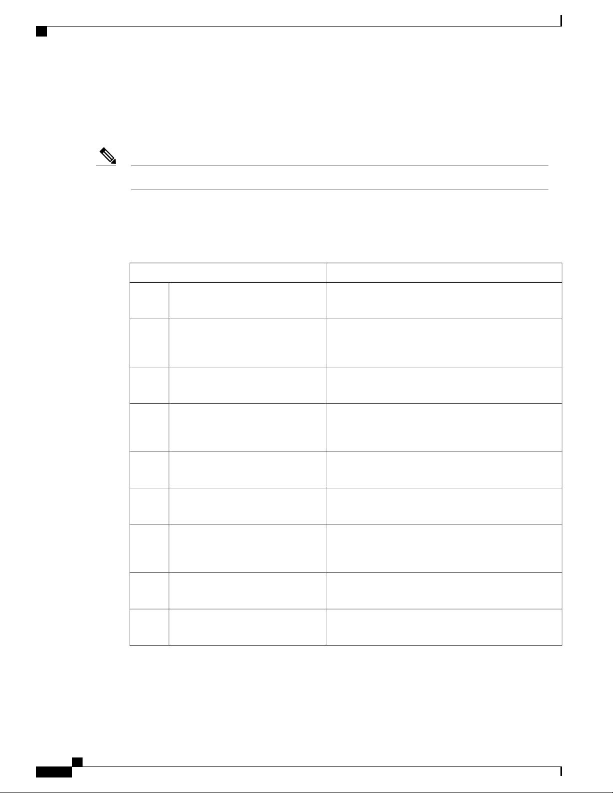
Document Organization
The following table describes the chapters and appendixes in this installation guide:
Preface
DescriptionChapter and Appendix
Overview1
Supported Hardware Components2
Preparing Your Site for Installation3
Installing the Router4
Power Up and Initial Configuration5
License Verification6
Removing and Replacing FRUs7
Technical SpecificationsA
Provides an overview of the Cisco ASR 1001-HX Router
and Cisco ASR 1002-HX Router
Provides an overview of the hardware components for the
Cisco ASR 1001-HX Router and Cisco ASR 1002-HX
Router
Provides site preparation guidelines for installing the Cisco
ASR 1001-HX Router and Cisco ASR 1002-HX Router
Provides information about the installation methods and
steps to install the Cisco ASR 1001-HX Router and Cisco
ASR 1002-HX Router
Provides basic system startup and initial configuration
information
Provides information about the Cisco ASR 1001-HX
Router and Cisco ASR 1002-HX Router licenses
Provides instructions for removing and replacing the
various FRUs in the Cisco ASR 1001-HX Router and Cisco
ASR 1002-HX Router
Provides router specifications for the Cisco ASR 1001-HX
Router and Cisco ASR 1002-HX Router
Port Signals and PinoutsB
Cisco ASR 1001-HX Router and Cisco ASR 1002-HX Router Hardware Installation Guide
x
Lists pinout specifications for the Cisco ASR 1001-HX
Router and Cisco ASR 1002-HX Router
Page 11
Preface
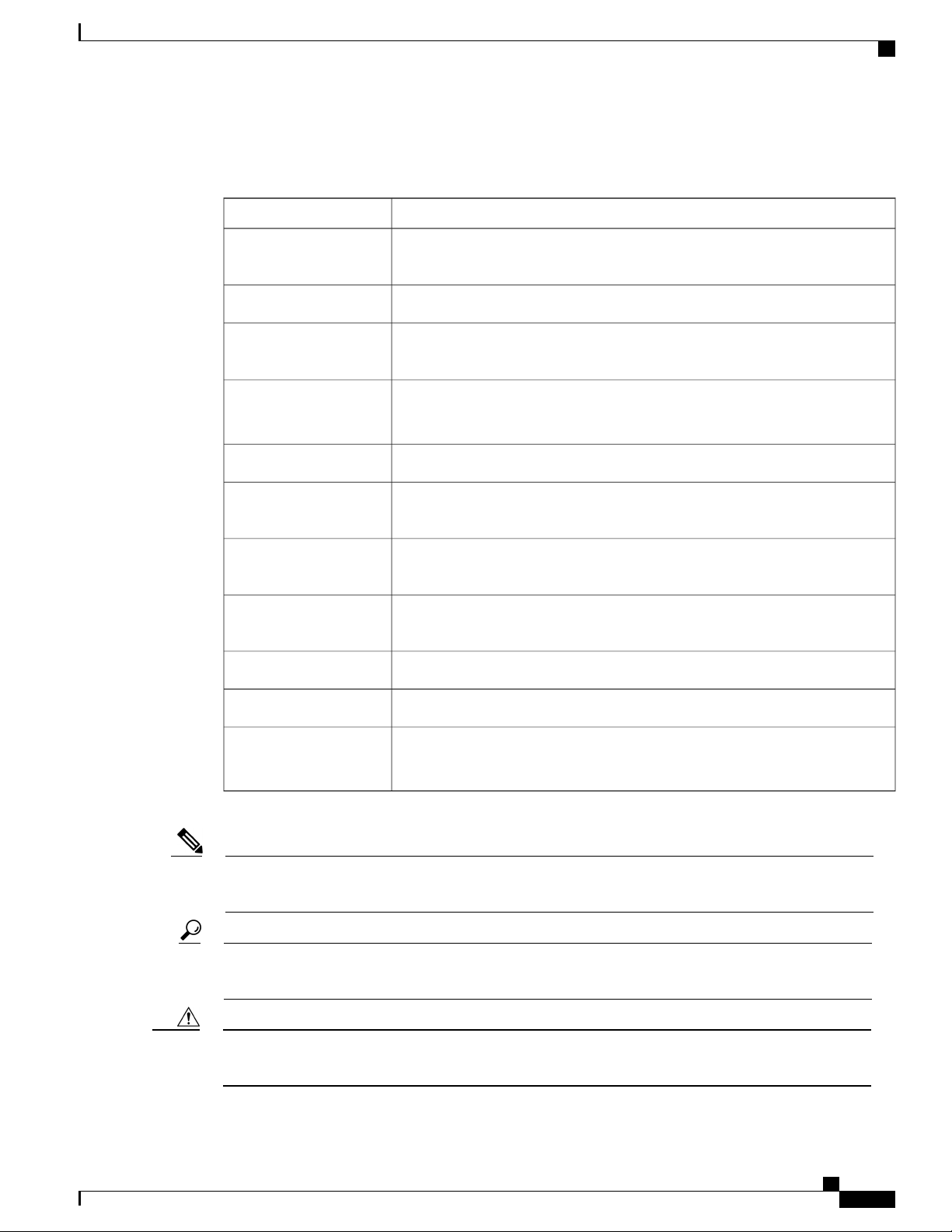
Conventions
Conventions
IndicationText Type
User input
Document titles
System output
CLI commands
{x | y | z}
[x | y | z]
string
Text the user should enter exactly as shown or keys a user should press appear
in this font.
Document titles appear in this font.
Terminal sessions and information that the system displays appear in this
font.
CLI command keywords appear in this font.
Variables in a CLI command appear in this font.
Elements in square brackets are optional.[ ]
Required alternative keywords are grouped in braces and separated by vertical
bars.
Optional alternative keywords are grouped in brackets and separated by vertical
bars.
A nonquoted set of characters. Do not use quotation marks around the string or
the string will include the quotation marks.
Nonprinting characters such as passwords are in angle brackets.< >
Note
Tip
Caution
Default responses to system prompts are in square brackets.[ ]
!
#
Means reader take note. Notes contain helpful suggestions or references to material not covered in the
document.
Means the following information will help you solve a problem. The tips information might not be
troubleshooting or even an action, but could be useful information, similar to a Timesaver.
Means reader be careful. In this situation, you might perform an action that could result in equipment
damage or loss of data.
An exclamation point (!) or a pound sign (#) at the beginning of a line of code
indicates a comment line.
Cisco ASR 1001-HX Router and Cisco ASR 1002-HX Router Hardware Installation Guide
xi
Page 12

Related Documentation
Preface
Timesaver
Warning
Means the described action saves time. You can save time by performing the action described in the
paragraph.
IMPORTANT SAFETY INSTRUCTIONS
This warning symbol means danger. You are in a situation that could cause bodily injury. Before you
work on any equipment, be aware of the hazards involved with electrical circuitry and be familiar with
standard practices for preventing accidents. Use the statement number provided at the end of each warning
to locate its translation in the translated safety warnings that accompanied this device.
SAVE THESE INSTRUCTIONS
Related Documentation
See the following documentation for Cisco ASR 1001-HX Router:
Release Notes for Cisco ASR 1000 Series, Cisco IOS XE Denali 16.3
•
Open Source Used In Cisco ASR 1001-HX Router
•
Cisco IOS XE Denali 16.3 Migration Guide for Access and Edge Routers
•
See the following documentation for Cisco ASR 1002-HX Router:
Release Notes for Cisco ASR 1000 Series, Cisco IOS XE Denali 16.2
•
Open Source Used In Cisco ASR 1002-HX Router
•
Cisco IOS XE Denali 16.2 Migration Guide for Access and Edge Routers
•
The Documentation Roadmap for Cisco ASR 1000 Series, Cisco IOS XE Denali 16.x provides links to all
Cisco ASR 1000 Series product documentation.
Obtaining Documentation and Submitting a Service Request
For information on obtaining documentation, submitting a service request, and gathering additional information,
see the monthly What's New in Cisco Product Documentation, which also lists all new and revised Cisco
technical documentation.
Subscribe to the What's New in Cisco Product Documentation as a Really Simple Syndication (RSS) feed
and set content to be delivered directly to your desktop using a reader application. The RSS feeds are a free
service and Cisco currently supports RSS version 2.0.
xii
Cisco ASR 1001-HX Router and Cisco ASR 1002-HX Router Hardware Installation Guide
Page 13

CHAPTER 1
Overview
The Cisco ASR 1000 Series Aggregation Services Routers are mid-range edge routers that establish a new
price-to-performance class offering benefits to both enterprise and service providers alike. The Cisco ASR
1000 Series Aggregation Services Routers portfolio is based on an innovative custom-built ASIC called
Quantum Flow Processor that aggregates services at scale.
The Cisco ASR 1001-HX Router and Cisco ASR 1002-HX Router are a part of the Cisco ASR 1000 Series
and offers a compact form factor that consumes less rack space and power while offering 100 Gbps forwarding
throughput. The Cisco ASR 1001-HX Router and Cisco ASR 1002-HX Router support all the general-purpose
routing and security features of the Cisco ASR 1000 Series Aggregation Services Routers.
Hardware Features, page 1
•
Cisco Product Identification Standard, page 11
•
Serial Number and PID/VID Label Location, page 14
•
Hardware Features
The Cisco ASR 1001-HX Router supports:
Up to 16 GB (8 GB in the base configuration) of DDR3 error-correcting code-protected field-replaceable
•
memory, with single-bit error correction and multi-bit error detection.
A fixed forwarding processor with up to 60 Gbps sustained forwarding data traffic through the chassis.
•
Up to 20 Gbps security and crypto processing through a dedicated security processor.
•
RJ-45 console ports and auxiliary ports, and a mini USB console port.
•
32 GB internal bootflash storage.
•
One copper Ethernet 10/100/1000 Mbps network management port.
•
An embedded USB (eUSB) flash module that supports 32 GB of nonvolatile Flash storage.
•
Two USB 2.0 ports for USB flash sticks.
•
Eight built-in 1 GE SFP ports in Bay 0; eight built-in 10 GE SFP+ ports in Bay 1 (capable of SyncE and
•
MACsec); and the last four ports in Bay 1 can be used as 1 GE by inserting a 1 GE SFP port.
Stratum 3E network clocking per GR-1244-CORE, using 10 GE, or 1 GE interfaces as timing sources.
•
Cisco ASR 1001-HX Router and Cisco ASR 1002-HX Router Hardware Installation Guide
1
Page 14

Hardware Features
Software redundancy using Dual IOS, similar to all the other non-hardware redundant routers from the
•
Cisco ASR 1000 Series Aggregation Services Router family.
LED indicators for Ethernet and console status, as well as visual system state indications.
•
Command-line interface (CLI), alarm, network management, logging, statistics aggregation, and on-board
•
failure logging (OBFL).
Environmental chassis management.
•
80 Mb ternary content-addressable memory (TCAM).
•
Field-replaceable units (FRU).
•
See Chapter 2, Supported Hardware Components for information on supported FRUs.
Field-replaceable Crypto Processor.
•
The Cisco ASR 1002-HX Router supports:
Up to 32 GB (16 GB in the base configuration) of DDR3 error-correcting code-protected field-replaceable
•
memory, with single-bit error correction and multi-bit error detection.
Overview
A fixed forwarding processor with up to 100 Gbps sustained forwarding data traffic through the chassis.
•
Up to 25 Gbps security and crypto processing through a dedicated security processor.
•
RJ-45 console ports and auxiliary ports, and a mini USB console port.
•
32 GB internal bootflash storage.
•
One copper Ethernet 10/100/1000 Mbps network management port.
•
An embedded USB (eUSB) flash module that supports 32 GB of nonvolatile Flash storage.
•
Two USB 2.0 ports for USB flash sticks.
•
Eight built-in 1 GE SFP-only interfaces, and eight built-in 10 GE SFP+ interfaces that support SyncE.
•
One Ethernet Port Adapter (EPA) bay.
•
Stratum 3E network clocking per GR-1244-CORE, using 1 GE, 10 GE, or EPA interfaces as timing
•
sources.
Software redundancy using Dual IOS, similar to all the other non-hardware redundant routers from the
•
Cisco ASR 1000 Series Aggregation Services Router family.
LED indicators for Ethernet and console status, as well as visual system state indications.
•
Command-line interface (CLI), alarm, network management, logging, statistics aggregation, and on-board
•
failure logging (OBFL).
Environmental chassis management.
•
80 Mb ternary content-addressable memory (TCAM).
•
Field-replaceable units (FRU) with online insertion and removal (OIR).
•
See Chapter 2, Supported Hardware Components for information on supported FRUs.
Cisco ASR 1001-HX Router and Cisco ASR 1002-HX Router Hardware Installation Guide
2
Page 15
Overview
Front View
Front View
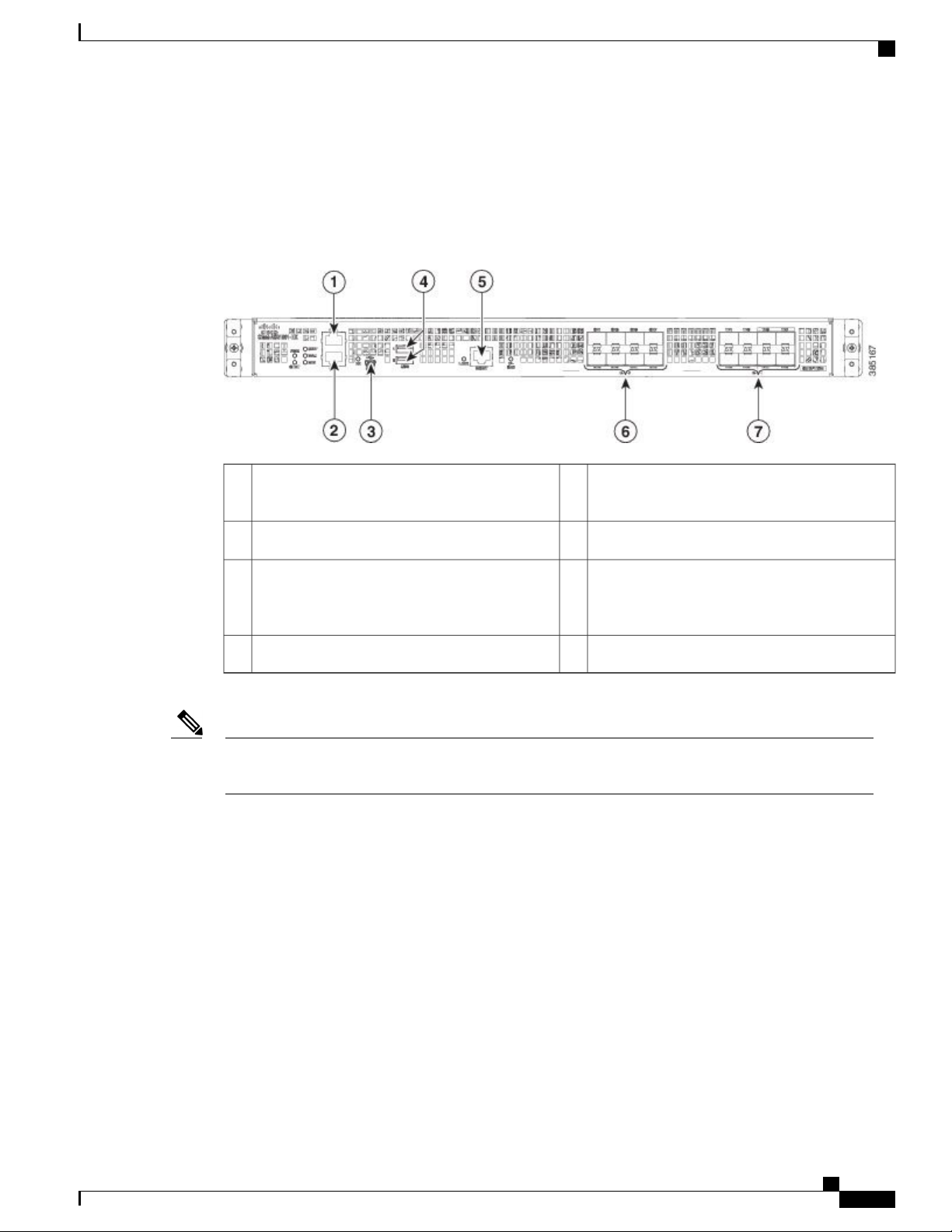
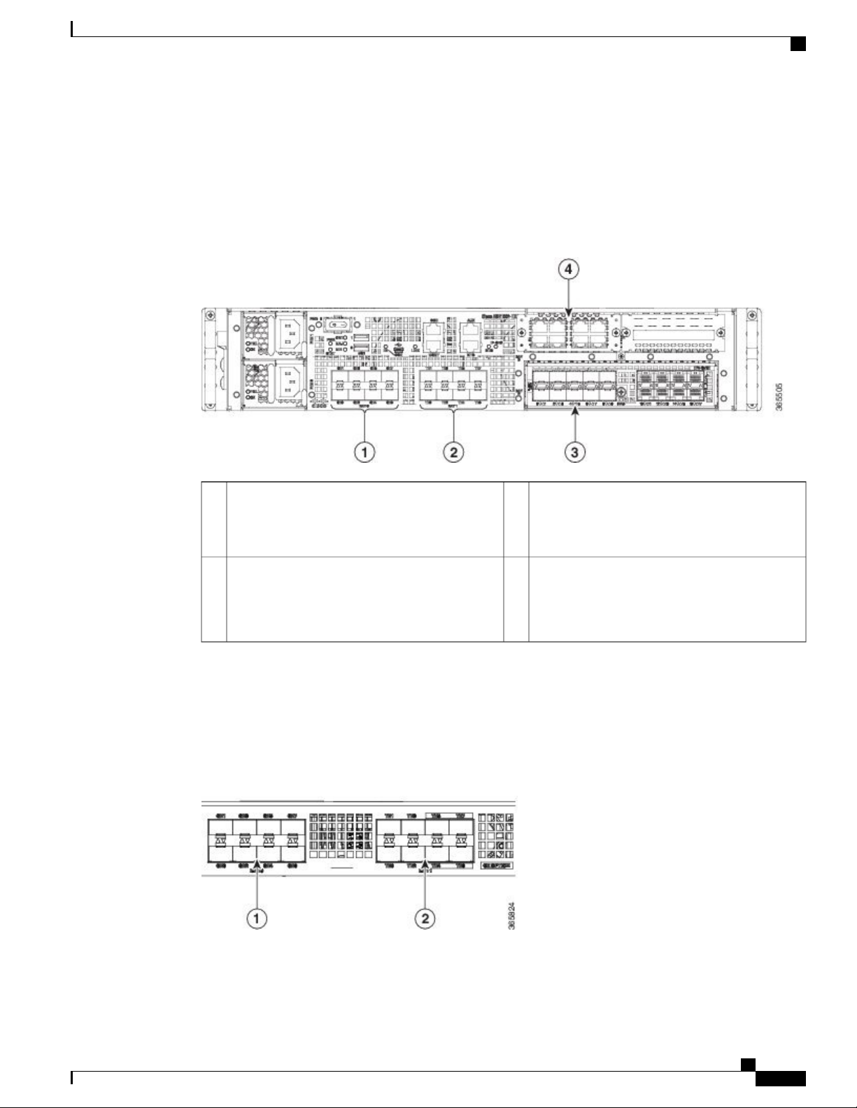
The following figure shows the front of the Cisco ASR 1001-HX Router.
Figure 1: Cisco ASR 1001-HX Router Front View
Note
1
AUX—RJ-45/RS-232 compatible auxiliary port
5
MGMT—RJ-45 10/100/1000 management
Ethernet port
2
CON—RJ-45/RS-232 compatible console port
3
CON—Mini USB console port
6
Bay 0—1GE SFP ports
7
Bay 1—The first four ports are strictly 10GE
SFP+ ports. The last four ports can be used as
1GE SFP or 10GE SFP+ ports
USB ports 0 and 14
For the Cisco ASR 1001-HX Router, the power supplies (PEM 0 and PEM1), are located in the rear of
the chassis. See Rear View, on page 10.
Cisco ASR 1001-HX Router and Cisco ASR 1002-HX Router Hardware Installation Guide
3
Page 16
Front View
Overview
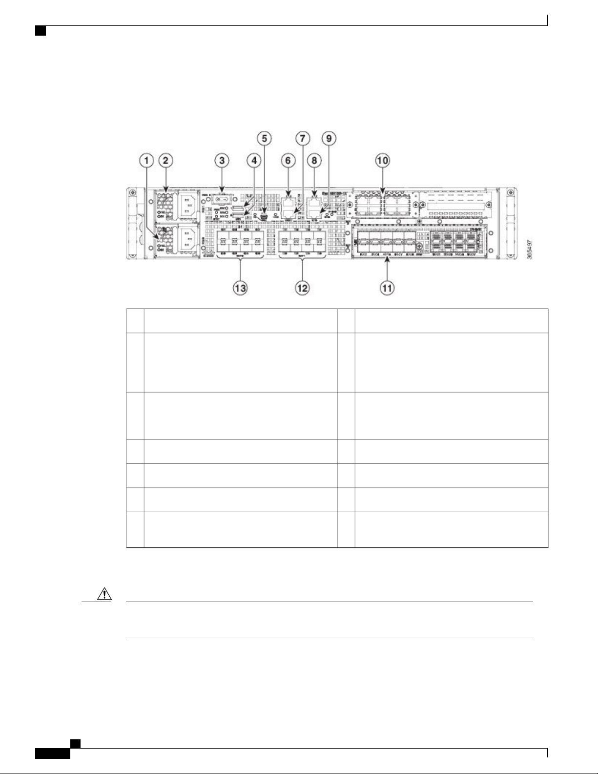
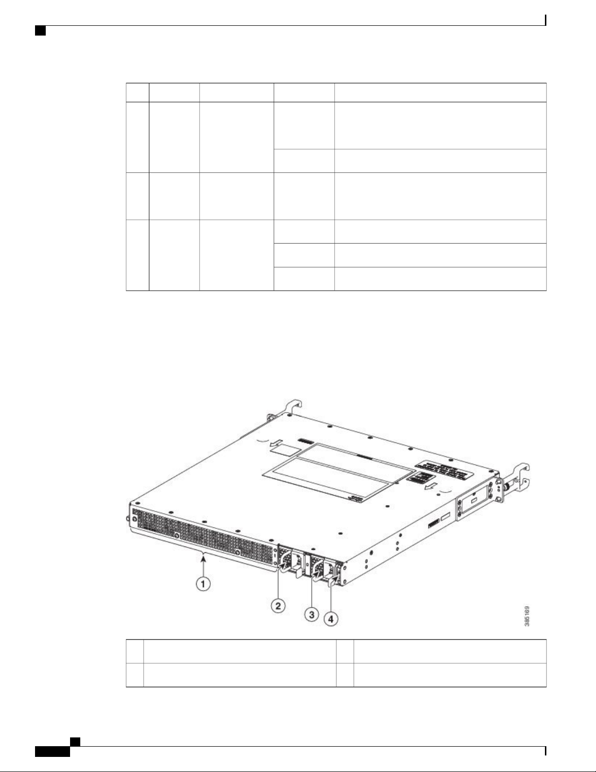
The following figure shows the front of the Cisco ASR 1002-HX Router.
Figure 2: Cisco ASR 1002-HX Router Front View
8Power supply (PEM 0)1
AUX—RJ-45/RS-232 compatible auxiliary port
9Power supply (PEM 1)2
BITS—RJ-48 Building Integrated Timing Supply
port
Note
The BITS port is not supported in this
software release.
10Power (PWR) switch3
Bay 3—NIM slot
Note
NIMs are not supported in this software
release.
11USB ports 0 and 14
Bay 2—EPA slot
5
CON—Mini USB console port
6
CON—RJ-45/RS-232 compatible console port
7
MGMT—RJ-45 10/100/1000 management
12
Bay 1—10GE SFP+ ports
13
Bay 0—1GE SFP ports
Ethernet port
Two power supplies (AC or DC) are accessed from the front of the router and are hot-swappable.
Caution
The Cisco ASR 1002-HX Router can support two AC or two DC power supplies. Do not install mixed
AC and DC power supply units in the same chassis.
Cisco ASR 1001-HX Router and Cisco ASR 1002-HX Router Hardware Installation Guide
4
Page 17
Overview
Slot Numbering
Front View
The Cisco ASR 1002-HX Router supports one Ethernet port adapter (EPA) in Bay 2.
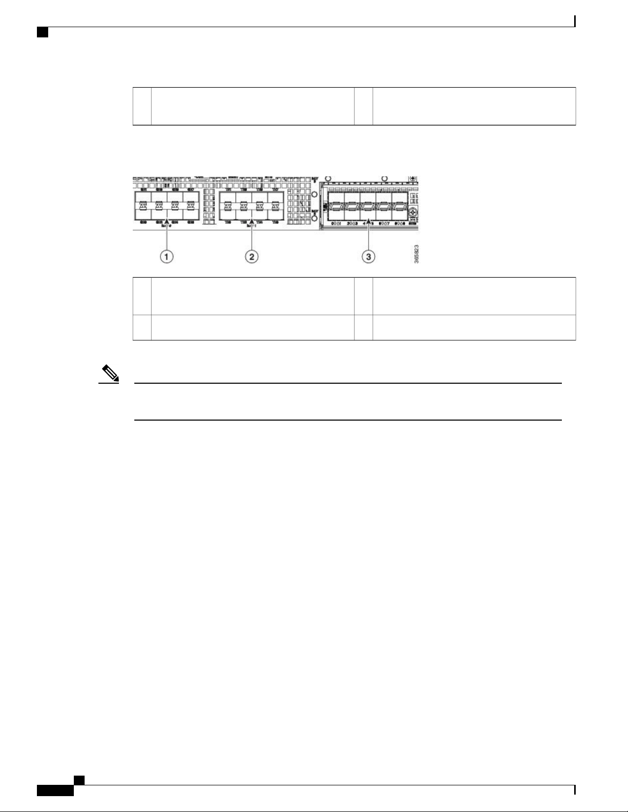
The following figure shows slot numbering on the Cisco ASR 1002-HX Router.
Figure 3: Cisco ASR 1002-HX Router Slot Numbering
1
Bay 0—Subslot 0/0/n connected to the built-in
1GE SFP interfaces
2
Bay 1—Subslot 0/1/n connected to the built-in
10GE SFP+ interfaces
Built-In SFP and SFP+ Ports
The following figure shows the port numbering for the built-in ports.
Figure 4: Cisco ASR 1001-HX Router Port Numbering
3
Bay 2—Subslot 0/2/n connected to the EPA
interfaces
See Supported EPAs, on page 15.
4
Bay 3—Subslot 0/3/n connected to the NIM
interfaces
Note
NIMs are not supported in this software
release.
Cisco ASR 1001-HX Router and Cisco ASR 1002-HX Router Hardware Installation Guide
5
Page 18
Front View
Overview
Note
1
Bay 0—The ports in Bay 0 use 1GE SFP
transceivers and are labeled GE0 - GE7.
Figure 5: Cisco ASR 1002-HX Router Port Numbering
1
Bay 0—The ports in Bay 0 use 1GE SFP
transceivers and are labeled GE0 - GE7.
3
Bay 2—EPA Slot
2
Bay 1— Ports TE4 - TE7 use 1GE SFP and ports
TE0 - TE3 use 10GE SFP+ transceivers.
2
Bay 1— The ports in Bay 1 use 10GE SFP+
transceivers and are labeled TE0 - TE7.
Interfaces from 0 - 3 on both Bay 0 and Bay 1 on the Cisco ASR 1001-HX Router and Cisco ASR 1002-HX
Router are enabled by default. Interfaces from 4 - 7 can be enabled by purchasing the Paired Port License.
The port LEDs behave as follows:
• Off—Indicates the port is not enabled by software.
• Amber—Indicates the port is enabled by software but there is a problem with the link.
• Green—Indicates the port is enabled by software and there is valid link.
Cisco ASR 1001-HX Router and Cisco ASR 1002-HX Router Hardware Installation Guide
6
Page 19
Overview
Management and Storage Connections
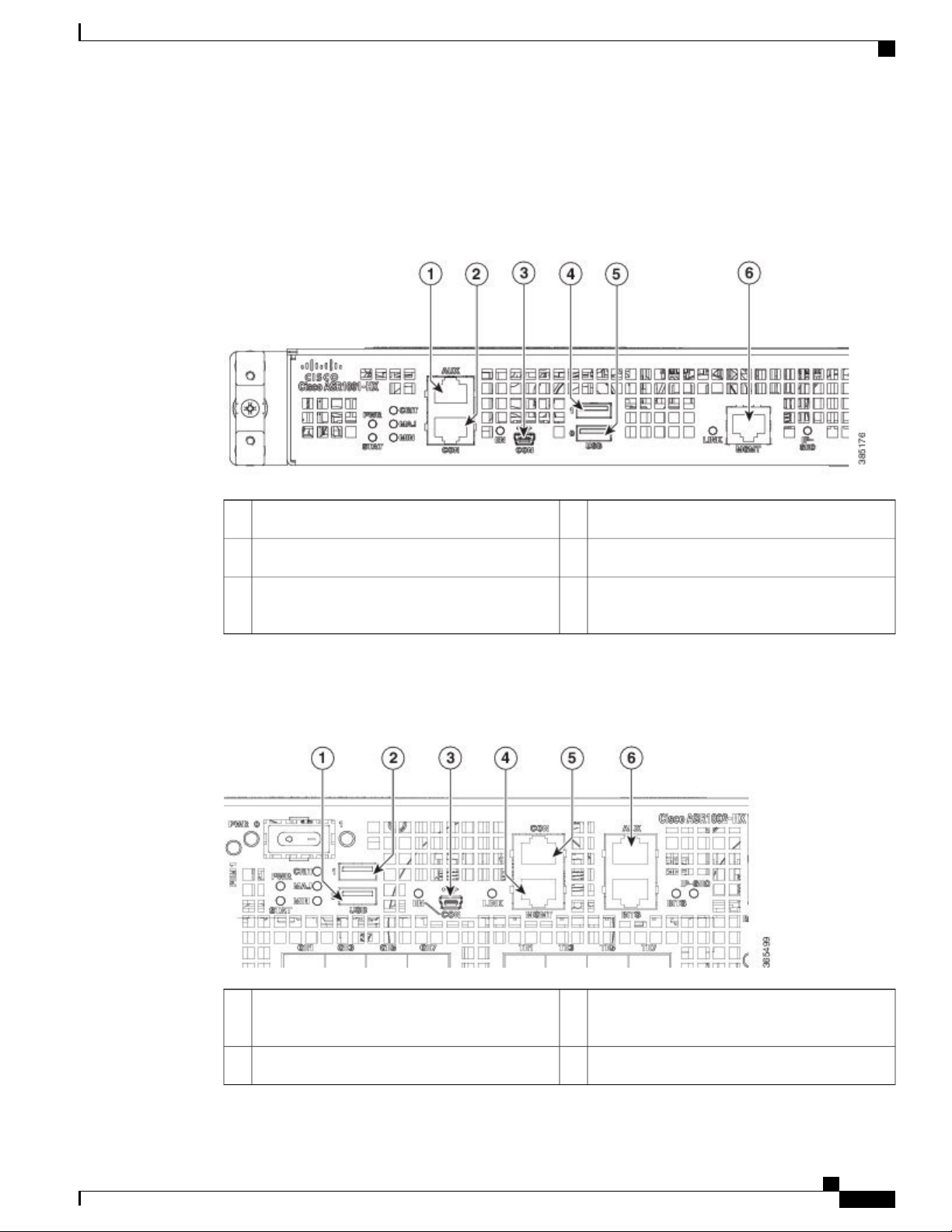
The following figure shows the management and storage connections for the ASR 1001-HX Router.
Figure 6: Management and Storage Connections for the Cisco ASR 1001-HX Router
Front View
1
AUX—RJ-45/RS-232 compatible auxiliary port.
2
CON—RJ-45/RS-232 compatible console port.
3
CON—Mini USB connector console port.
USB port 14
USB port 05
6
MGMT—RJ-45 10/100/1000 management
Ethernet port.
The following figure shows the management and storage connections for the ASR 1002-HX Router.
Figure 7: Management and Storage Connections for the Cisco ASR 1002-HX Router
4USB port 01
MGMT—RJ-45 10/100/1000 management
Ethernet port.
5USB port 12
CON—RJ-45/RS-232 compatible console port.
Cisco ASR 1001-HX Router and Cisco ASR 1002-HX Router Hardware Installation Guide
7
Page 20

Front View
Overview
LEDs
3
CON—Mini USB connector console port.
6
AUX—RJ-45/RS-232 compatible auxiliary port.
The following figure shows the LEDs on the front panel of the Cisco ASR 1001-HX Router.
Figure 8: Cisco ASR 1001-HX LEDs
BehaviorColorDescriptionLED LabelNo.
Cisco IOS has successfully booted.GreenStatusSTATUS1
The system is at ROMMON.Amber
System failure.Red
All the power supplies are within operational limits.GreenPowerPWR2
Major alarm indicator.RedMajor alarmMAJ3
Critical alarm indicator.RedCritical alarmCRIT4
Minor alarm indicator.AmberMinor alarmMIN5
EN6
GreenUSB console
enable
Off
Indicates that the mini USB connector is used as the
console.
Indicates that the RJ-45 connector is being used as
the console.
ManagementLINK7
Blinking
green
Indicates the negotiated Ethernet speed (1 blink equals
10 Mbps, 2 blinks equals 100 Mbps, 3 blinks equals
1000 Mbps).
Not connected.Off
Cisco ASR 1001-HX Router and Cisco ASR 1002-HX Router Hardware Installation Guide
8
Page 21
Overview
Front View
BehaviorColorDescriptionLED LabelNo.
Indicates the crypto module is present and operational.GreenCrypto moduleIP-SEC8
Indicates the crypto module is present but inoperable.Amber
Indicates the crypto module is not installed.Off
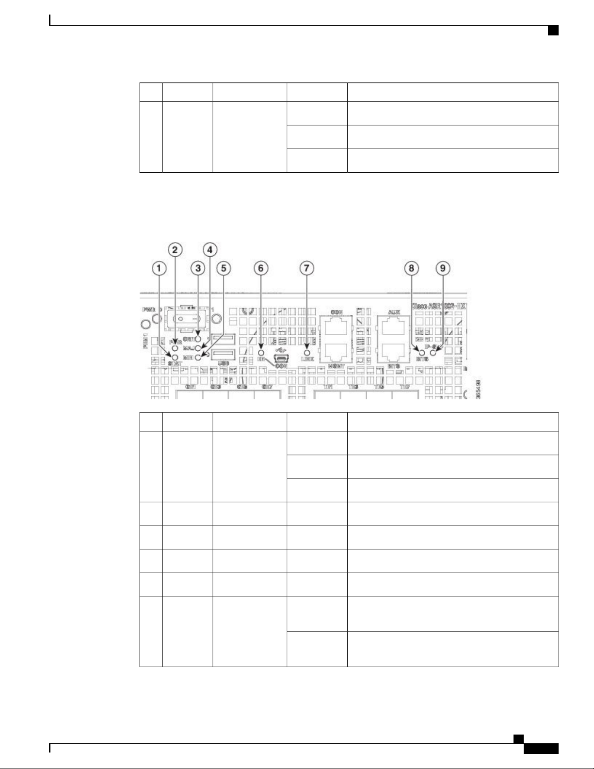
The following figure shows the LEDs on the front panel of the Cisco ASR 1002-HX Router.
Figure 9: Cisco ASR 1002-HX LEDs
BehaviorColorDescriptionLED LabelNo.
Cisco IOS has successfully booted.GreenStatusSTATUS1
The system is at ROMMON.Amber
System failure.Red
All the power supplies are within operational limits.GreenPowerPWR2
Critical alarm indicator.RedCritical alarmCRIT3
Major alarm indicator.RedMajor alarmMAJ4
Minor alarm indicator.AmberMinor alarmMIN5
EN6
GreenUSB console
enable
Off
Indicates that the mini USB connector is used as the
console.
Indicates that the RJ-45 connector is being used as
the console.
Cisco ASR 1001-HX Router and Cisco ASR 1002-HX Router Hardware Installation Guide
9
Page 22
Rear View
Overview
BehaviorColorDescriptionLED LabelNo.
Rear View
ManagementLINK7
Blinking
green
Indicates the negotiated Ethernet speed (1 blink equals
10 Mbps, 2 blinks equals 100 Mbps, 3 blinks equals
1000 Mbps).
Not connected.Off
BITS8
OffBuilding
Integrated Timing
The BITS port is not supported in this software
release.
Supply (BITS)
Indicates the crypto module is present and operational.GreenCrypto moduleIP-SEC9
Indicates the crypto module is present but inoperable.Amber
Indicates the crypto module is not installed.Off
The following figure shows the rear of the Cisco ASR 1001-HX Router.
Figure 10: Cisco ASR 1001-HX Router Rear View
Power supply (PEM 0)3Fans1
Power/standby switch4Power supply (PEM 1)2
Cisco ASR 1001-HX Router and Cisco ASR 1002-HX Router Hardware Installation Guide
10
Page 23
Overview
Cisco Product Identification Standard
The chassis has a front-to-rear airflow. Six internal fans draw cooling air into the chassis and across internal
components to maintain an acceptable operating temperature. The fans are numbered from 0 to 5, right to left.
Two power supplies (AC or DC) are accessed from the rear of the router and are hot-swappable.
Caution
The Cisco ASR 1001-HX Router can support two AC or two DC power supplies. Do not install mixed
AC and DC power supply units in the same chassis.
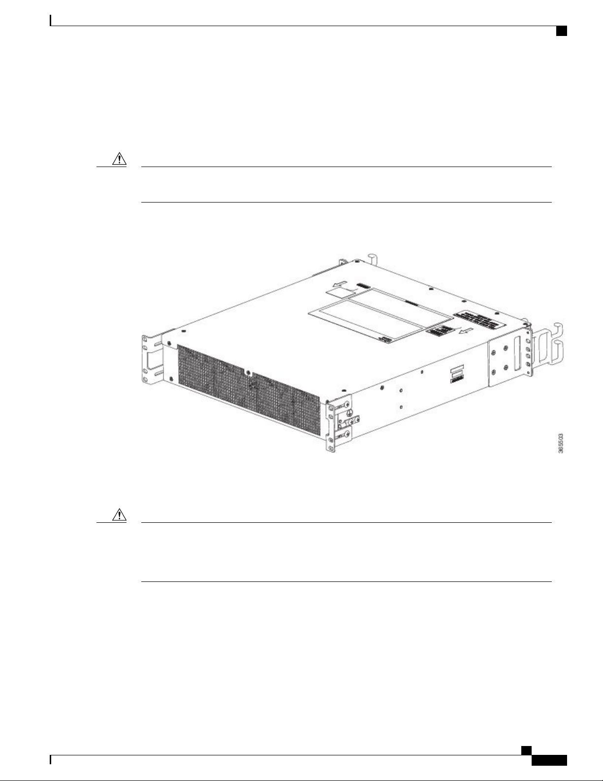
The following figure shows the rear of the Cisco ASR 1002-HX Router.
Figure 11: Cisco ASR 1002-HX Router Rear View
The chassis has a front-to-rear airflow. Four internal fans draw cooling air in through the front of the chassis
and across internal components to maintain an acceptable operating temperature. The fans are located at the
rear of the chassis. The fans are numbered from 0 to 3, right to left.
Caution
The power supplies used in Cisco ASR 1001-HX Router and Cisco ASR 1002-HX Router are different
and they should not be mixed or swapped. The size and structural dimensions are the same, therefore they
both look alike. It would be hazardous if you accidently inserted the wrong power supply into the PEM
slot.
Cisco Product Identification Standard
This section describes the Cisco products and services product identification standard. This feature provides
you with the ability to effectively integrate and manage Cisco products in your network and business operations.
Cisco ASR 1001-HX Router and Cisco ASR 1002-HX Router Hardware Installation Guide
11
Page 24
Unique Device Identifier
Unique Device Identifier
The Unique Device Identifier (UDI) is the Cisco product identification standard for hardware products. A
product identification standard removes barriers to enterprise automation and can help you reduce operating
expenses.
The UDI provides a consistent electronic, physical, and associated business-to-business information product
identification standard.
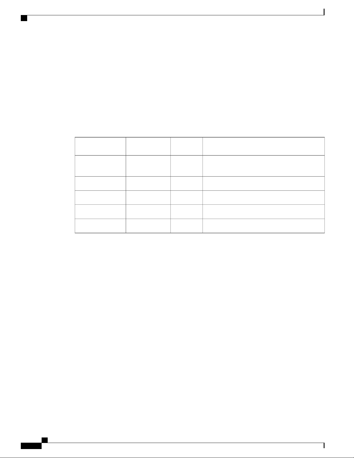
The UDI is a combination of five data elements. The following table lists the UDI elements.
Table 1: UDI Elements
Overview
UDI Data Element
Electronic
Visibility
Visibility
YesYesPID
DescriptionPhysical
Product ID, also known as product name, model
name, product number
Version IDYesYesVID
Serial number, the unique instance of the PIDYesYesSN
YesEntity Name
YesProduct Description
—
—
Type, such as chassis, slot, or power supply
Additional product information
The combination of serial number and product ID (PID) is unique and consistent across all Cisco products.
The PID that is coded on hardware is called a base product identifier.
Additional orderable PIDs can be associated to a base PID. For instance, an orderable PID may describe a
packaging configuration for a product or a bundled group of products sold, tested, and shipped together.
Specific unique device identifier (UDI) benefits include the following:
Identifies:
•
Individual Cisco products in your networks
◦
PIDs and serial numbers for service and replaceable products
◦
Version IDs (VIDs) for product version visibility
◦
Facilitates discovery of products subject to recall or upgrade
•
Enhances inventory automation of Cisco products
•
The Cisco product identification standard provides the following features:
• Version visibility—Cisco continuously improves products through feature additions. Product changes
are indicated by incrementing the VID, which provides version visibility to help you understand and
manage product changes. VID management ensures consistency of changes from product to product.
Cisco ASR 1001-HX Router and Cisco ASR 1002-HX Router Hardware Installation Guide
12
Page 25
Overview
Unique Device Identifier
• Operating expense reduction—Cisco UDIs provide accurate and detailed network inventory information;
identifying each Cisco product in a network element through a standard interface. Cisco operating
systems can view and use this data, allowing you to automate your electronic inventory.
• Consistency across product layers—The UDIs are embedded in the hardware products and cannot be
overwritten. Operating and management systems discover UDIs through standard interfaces and display
UDIs in standard outputs. Standard interfaces include the IETF standard ENTITY-MIB.
show diag chassis eeprom detail Command
The show diag chassis eeprom command displays the PID, VID, PCB serial number, hardware revision, and
other such information.
The following is sample output from the show diag chassis eeprom command:
Router# show diag chassis eeprom
MIDPLANE EEPROM data:
Product Identifier (PID) : ASR1002-HX
Version Identifier (VID) : V00
PCB Serial Number : JAE1931098U
Top Assy. Part Number : 68-5448-02
Hardware Revision : 0.3
Asset ID :
CLEI Code : SAMPL00XYZ
Note
Common Language Equipment Identification (CLEI) code is a ten-digit character code that identifies a
specific product. A CLEI code is applied to each part within a Cisco ASR1002-HX Router as they are
programmed in manufacturing for shipment to customers.
show license udi Command
The show license udi command displays UDI information.
The following is sample output from the show license udi command:
Router# show license udi
SlotID PID SN UDI
-------------------------------------------------------------------------------* ASR1002-HX JAE1931098U ASR1002-HX:JAE1931098U
For complete information on the product identification standard, see http://www.cisco.com/go/udi/.Note
Cisco ASR 1001-HX Router and Cisco ASR 1002-HX Router Hardware Installation Guide
13
Page 26
Serial Number and PID/VID Label Location
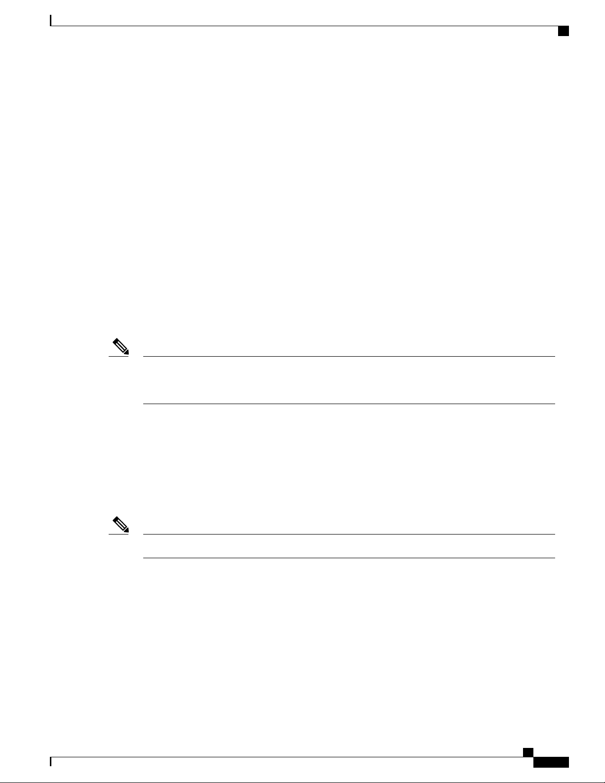
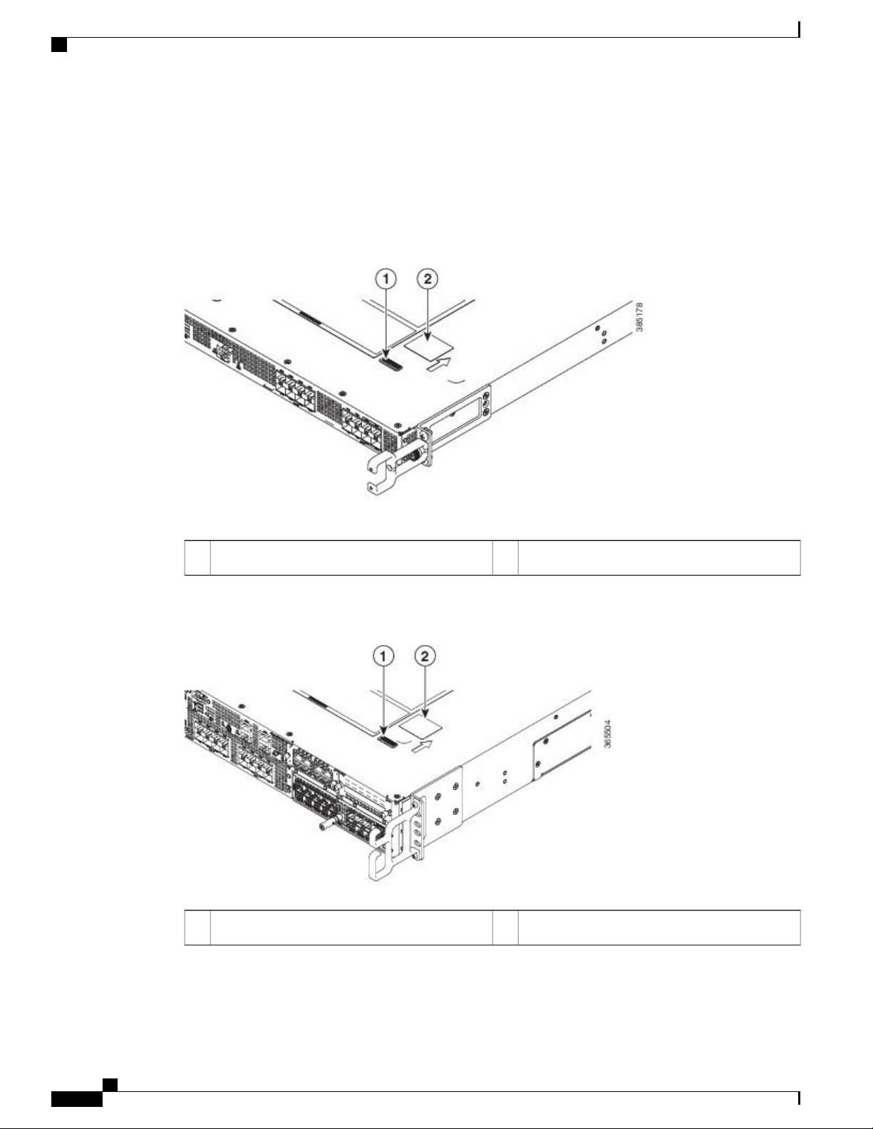
Serial Number and PID/VID Label Location
The following figures show the location of the serial number and the PID/VID label on the Cisco ASR 1001-HX
Router and Cisco ASR 1002-HX Router.
Figure 12: Cisco ASR 1001-HX Router Serial Number and PID/VID Label Location
Overview
PID/VID Label2Serial Number1
Figure 13: Cisco ASR 1002-HX Router Serial Number and PID/VID Label Location
PID/VID Label2Serial Number1
Cisco ASR 1001-HX Router and Cisco ASR 1002-HX Router Hardware Installation Guide
14
Page 27

Supported Hardware Components
This chapter contains information about the supported hardware components on the Cisco ASR 1001-HX
Router and Cisco ASR 1002-HX Router, and contains the following sections:
Supported EPAs, page 15
•
Supported Transceivers, page 17
•
Supported Crypto Module, page 19
•
Supported DIMM Upgrade , page 20
•
Power Supplies, page 20
•
Supported EPAs
The following table lists the supported EPAs on the Cisco ASR 1002-HX Router.
CHAPTER 2
EPA-18X1GE
EPA-10X10GE
DescriptionPID
Eighteen 1GE-ports that support small form-factor pluggable (SFP)
optical transceivers to provide network connectivity. Ports are numbered
0 – 17.
See Table 3: Supported SFP Transceivers, on page 18 for supported
transceivers.
Ten 10GE-ports that support small form-factor pluggable (SFP+) optical
transceivers to provide network connectivity. Ports are numbered 0 –
9.
See Table 4: Supported SFP+ Transceivers, on page 18 for supported
transceivers.
Cisco ASR 1001-HX Router and Cisco ASR 1002-HX Router Hardware Installation Guide
15
Page 28
Supported EPAs
Supported Hardware Components
DescriptionPID
EPA-6X10GE
EPA-6X10GE uses small form-factor pluggable (SFP+) optical
transceivers to provide network connectivity. Ports are numbered 0 –
5.
See Table 4: Supported SFP+ Transceivers, on page 18 for supported
transceivers.
EPA-1X100GE
EPA-1X100GE uses a CPAK module to provide network connectivity.
See Table 5: Supported CPAK Interface, on page 19 for supported
CPAKs.
EPA-CPAK-2X40GE
EPA-CPAK-2X40GE uses a CPAK module and a 2x40 GE breakout
cable to provide network connectivity
See Table 5: Supported CPAK Interface, on page 19 for supported
CPAKs.
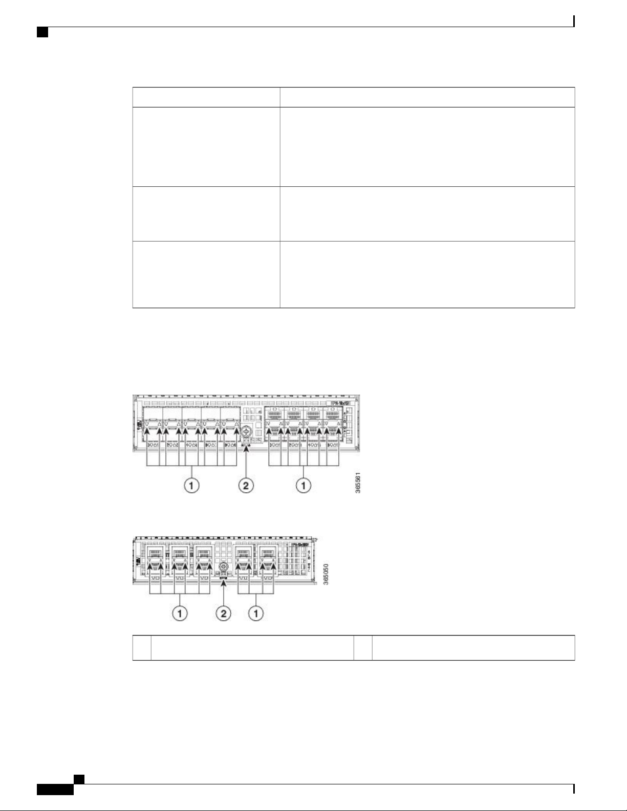
An EPA has two types of LEDs: an A/L (Active/Link) LED for each port on the EPA, and a STATUS LED,
as shown in the following figure.
Figure 14: EPA-18X1GE LEDs
Figure 15: EPA-10X10GE LEDs
STATUS2A/L1
Cisco ASR 1001-HX Router and Cisco ASR 1002-HX Router Hardware Installation Guide
16
Page 29
Supported Hardware Components
Table 2: EPA LEDs
Supported Transceivers
DescriptionColor or StateFunction
Port is enabled and the link is up.GreenA/L (Active/Link)
Related Topics
Removing and Replacing an EPA, on page 128
Supported Transceivers
The Cisco ASR 1001-HX Router and Cisco ASR 1002-HX Router support the following small form-factor
pluggable (SFP) and CPAK optical transceiver types:
Amber
Amber
Port is enabled and the link is
down.
Port is not enabled.Off
EPA is ready and operational.GreenStatus
EPA power is on and good, and the
EPA is being configured.
EPA power is off.Off
Cisco ASR 1002-HX RouterCisco ASR 1001-HX RouterPortsBay
Bay 0
Bay 1
Bay 2
Ports GE0 – GE7
Ports TE0 - TE3 use 10GE SFP+
EPA-10X10GE — Ports 0 – 9
EPA-1X100GE — Port 0
EPA-CPAK-2X40GE — Port 0 - 1
NIMBay 3
—EPA-18X1GE — Ports 0 – 17
—
SFPSFP
SFP+SFP or SFP+Ports TE4 - TE7 use 1GE SFP
SFP
SFP+
CPAK
CPAK
Not supported in this software
release.
Cisco ASR 1001-HX Router and Cisco ASR 1002-HX Router Hardware Installation Guide
17
Page 30
Supported Transceivers
Table 3: Supported SFP Transceivers
Supported Hardware Components
DescriptionPID
100BASE-FX SFP transceiver module, MMF, 1310nmGLC-GE-100FX
1000BASE-SX SFP transceiver module, MMF, 850nm, DOMGLC-SX-MMD
GLC-LH-SMD
1000BASE-LX/LH SFP transceiver module, MMF/SMF, 1310nm,
DOM
1000BASE-T SFP (NEBS 3 ESD)SFP-GE-T
1000BASE-BX SFP, 1310nmGLC-BX-U
1000BASE-BX SFP, 1490nmGLC-BX-D
1000BASE-T SFP transceiver module for category 5 copper wireGLC-TE
GE SFP, LC connector SX transceiverGLC-SX-MM
GE SFP, LC connector LX/LH transceiverGLC-LH-SM
GE SFP, LC Connector, EX transceiverGLC-EX-SMD
1000BASE-ZX SFP transceiver module, SMF, 1550nm, DOMGLC-ZX-SMD
1000BASE DWDMDWDM-SFP
1000BASE CWDMCWDM-SFP
Table 4: Supported SFP+ Transceivers
DescriptionPID
10GBASE-SR SFP+ Module for MMFSFP-10G-SR
10GBASE-SR SFP+ Module for Extended Temp rangeSFP-10G-SR-X
10GBASE-LR SFP+ Module for SMFSFP-10G-LR
10GBASE-LR SFP+ Module for Extended Temp rangeSFP-10G-LR-X
10GBASE-ER SFP+ Module for SMFSFP-10G-ER
10GBASE-CU SFP+ Cable 7 Meter, activeSFP-H10GB-ACU7M
10GBASE-CU SFP+ Cable 10 Meter, activeSFP-H10GB-ACU10M
Cisco ASR 1001-HX Router and Cisco ASR 1002-HX Router Hardware Installation Guide
18
Page 31

Supported Hardware Components
The following table lists the supported CPAK transceivers that can be used in the EPA-1x100GE Ethernet
port adapter.
Table 5: Supported CPAK Interface
Supported Crypto Module
DescriptionPID
CPAK-100G-SR10
CPAK-100G-LR4
Supported Crypto Module
The Cisco ASR 1001-HX Router and Cisco ASR 1002-HX Router support the following crypto module:
CPAK 100GBASE-SR10
Delivers 100-Gbps links over 24-fiber ribbon cables terminated with
MPO/MTP connectors. It supports link lengths of 100m and 150m on
laser-optimized OM3 and OM4 multifiber cables. OTN rates are also
supported.
CPAK 100GBASE-LR4
Supports 100-Gbps optical links over standard single-mode fiber (SMF,
G.652) terminated with SC connectors. Nominal power consumption
is less than 5.5W.
The LR4 module is IEEE 802.3ba-compliant and supports link lengths
of up to 10 km over standard SMF, G.652. It delivers an aggregate data
signal of 100-Gbps, carried over four wavelength-division multiplexing
(WDM) wavelengths operating at a nominal 25 Gbps per lane in LAN
mode. OTU4 rate is also supported. Optical multiplexing and
demultiplexing of the four wavelengths are managed within the module.
DescriptionPID
ASR1001HX-IPSECHW
ASR1002HX-IPSECHW
Related Topics
Installing the Crypto Module in a Cisco ASR 1001-HX Router, on page 140
Installing the Crypto Module in a Cisco ASR 1002-HX Router, on page 142
Cisco ASR 1001-HX Router and Cisco ASR 1002-HX Router Hardware Installation Guide
Cisco ASR1001-HX crypto module with no default crypto throughput.
You can upgrade the throughput (8 Gbps or 16 Gbps) by applying a
software-activated performance upgrade license.
Cisco ASR1002-HX crypto module with no default crypto throughput.
You can upgrade the throughput (8 Gbps, 16 Gbps, or 25 Gbps) by
applying a software-activated performance upgrade license.
19
Page 32

Supported DIMM Upgrade
Supported DIMM Upgrade
The Cisco ASR 1001-HX Router and Cisco ASR 1002-HX Router support the following DIMM upgrade:
Supported Hardware Components
DescriptionPID
M-ASR1001HX-16GB
M-ASR1002HX-32GB
Related Topics
Removing and Replacing a DIMM, on page 117
Power Supplies
The Cisco ASR 1001-HX Router and Cisco ASR 1002-HX Router support AC or DC power supply options.
The modular chassis configurations support the installation of two power supplies for redundancy. When an
external power supply fails or is removed, the other power supply provides power requirements for the chassis.
This allows you to hot-swap the power supply without impacting the functionality of the router.
Caution
A router can support two AC or two DC power supplies. Do not install mixed AC and DC power supply
units in the same chassis.
The Cisco ASR 1001-HX Router has two DIMM slots and supports
8-GB configuration by default (two 4-GB DIMMS), and can be upgraded
to 16-GB (two 8-GB DIMMS) configuration.
The Cisco ASR 1002-HX Router has four DIMM slots and supports
16-GB configuration by default (two 8-GB DIMMS), and can be
upgraded to 32-GB (four 8-GB DIMMS) configuration.
Caution
Cisco ASR 1001-HX Router and Cisco ASR 1002-HX Router Hardware Installation Guide
20
The power supplies used in Cisco ASR 1001-HX Router and Cisco ASR 1002-HX Router are different
and they should not be mixed or swapped. The size and structural dimensions are the same, therefore they
both look alike. It would be hazardous if you accidently inserted the wrong power supply into the PEM
slot.
The power supplies are used in a 1 + 1 redundant configuration. There is no input switch on the faceplate of
the power supplies. A power supply is switched from Standby to On by way of a system chassis power switch.
The following table lists the power supplies that you can order:
Power SupplyPart Number
ASR1000X-AC-750W
ASR1000X-AC-750W=
Cisco ASR 1002-HX Router power supply module with plug-side intake
airflow, A/C, 750W, 85–264V
Cisco ASR 1002-HX Router power supply module with plug-side intake
airflow, A/C, 750W, 85–264V, spare
Page 33

Supported Hardware Components
AC Power Supply
Power SupplyPart Number
Caution
ASR1000X-DC-950W
Cisco ASR 1002-HX Router power supply module with plug-side intake
airflow, DC 950W
ASR1000X-DC-950W=
Cisco ASR 1002-HX Router power supply module with plug-side intake
airflow, DC 950W, spare
ASR1000X-AC-750W-R
Cisco ASR 1001-HX Router power supply module with plug-side
exhaust airflow, A/C, 750W, 85–264V
ASR1000X-AC-750W-R=
Cisco ASR 1001-HX Router power supply module with plug-side
exhaust airflow, A/C, 750W, 85–264V, spare
ASR1000X-DC-950W-R
Cisco ASR 1001-HX Router power supply module with plug-side
exhaust airflow, DC 950W
ASR1000X-DC-950W-R=
Cisco ASR 1001-HX Router power supply module with plug-side
exhaust airflow, DC 950W, spare
The chassis has a front-to-rear airflow. All of the power supplies and fan modules in the chassis must use
the same airflow direction or an error will occur with possible overheating and shut down of the router.
If you power up the router with more than one airflow direction, you must power down the router and
replace the modules with the wrong airflow direction before powering up the router.
Related Topics
Removing and Replacing the Power Supplies, on page 111
AC Power Supply
Caution
Note
The power supplies used in Cisco ASR 1001-HX Router and Cisco ASR 1002-HX Router are different
and they should not be mixed or swapped. The size and structural dimensions are the same, therefore they
both look alike. It would be hazardous if you accidently inserted the wrong power supply into the PEM
slot.
The direction of the airflow is different for the Cisco ASR 1001-HX Router and the Cisco ASR 1002-HX
Router as shown by the arrows in the illustrations below.
Cisco ASR 1001-HX Router and Cisco ASR 1002-HX Router Hardware Installation Guide
21
Page 34

DC Power Supply
Supported Hardware Components
The following figure shows the Cisco ASR 1001-HX Router AC power supply.
Figure 16: ASR1000X-AC-750W AC Power Supply Used in the Cisco ASR 1001-HX Router
FAIL and OK LEDs3AC power connector1
Retaining latchHandle2
The following figure shows the Cisco ASR 1002-HX Router AC power supply.
Figure 17: ASR1000X-AC-750W AC Power Supply Used in the Cisco ASR 1002-HX Router
DC Power Supply
The ASR1000X-DC-950W input connector is a two-wire connector with connection polarity from left to right
(when facing the unit) of positive (+) negative (–).
The power supply has a handle to be used for insertion and extraction. The module must be supported with
one hand because of its length.
FAIL and OK LEDs3AC power connector1
Retaining latchHandle2
Cisco ASR 1001-HX Router and Cisco ASR 1002-HX Router Hardware Installation Guide
22
Page 35

Supported Hardware Components
DC Power Supply
Caution
Note
The power supplies used in Cisco ASR 1001-HX Router and Cisco ASR 1002-HX Router are different
and they should not be mixed or swapped. The size and structural dimensions are the same, therefore they
both look alike. It would be hazardous if you accidently inserted the wrong power supply into the PEM
slot.
The direction of the airflow is different for the Cisco ASR 1001-HX Router and the Cisco ASR 1002-HX
Router as shown by the arrows in the illustrations below.
The following figure shows the Cisco ASR 1001-HX Router DC power supply.
Figure 18: ASR1000X-DC-950W DC Power Supply Used in the Cisco ASR 1001-HX Router
FAIL and OK LEDs3DC power connections1
Retaining latchHandle2
Cisco ASR 1001-HX Router and Cisco ASR 1002-HX Router Hardware Installation Guide
23
Page 36

Power Supply LEDs
Supported Hardware Components
The following figure shows the Cisco ASR 1002-HX Router DC power supply.
Figure 19: ASR1000X-DC-950W DC Power Supply Used in the Cisco ASR 1002-HX Router
Power Supply LEDs
The following table describes the power supply LEDs.
Table 6: AC and DC Power Supply LEDs
current, over temperature and fan failure)
supply continues to operate (high temperature, high
power and slow fan)
FAIL and OK LEDs3DC power connections1
Retaining latchHandle2
Amber (FAIL) LED StatusGreen (OK) LED StatusPower Supply Condition
OFFOFFNo AC power to all power supplies
ONOFFPower Supply Failure (includes over voltage, over
1Hz BlinkingOFFPower Supply Warning events where the power
Cisco ASR 1001-HX Router and Cisco ASR 1002-HX Router Hardware Installation Guide
24
Page 37

Supported Hardware Components
Power Supply Fans
The fans in the power supply module are used for cooling the power supply module itself while system-level
cooling is provided by fans within the chassis. The power supplies do not depend on the system-level fans
for cooling. Fan failure is determined by fan-rotation sensors.
Power Supply Fans
Amber (FAIL) LED StatusGreen (OK) LED StatusPower Supply Condition
OFF1Hz BlinkingAC Present/3.3VSB on (PSU OFF)
OFFONPower Supply ON and OK
Note
Caution
Note
Power Cords
The fans in the Cisco ASR 1001-HX Router power supplies have plug-side exhaust airflow. The fans in
the Cisco ASR 1002-HX Router power supplies have plug-side intake airflow.
The chassis has a front-to-rear airflow. All of the power supplies and fan modules in the same chassis
must use the same airflow direction or an error will occur with possible overheating and shut down of the
router. If you power up the router with more than one airflow direction, you must power down the router
and replace the modules with the wrong airflow direction before powering up the router.
The fans in the power supply modules will run as soon as the power supply is plugged in, even if the
power switch is in the Standby position.
The following table lists the supported power cords.
DescriptionPower Cord Item Number
Power Cord, 110 VCAB-AC
Power Cord, Australia, 10 ACAB-ACA Plug
Power Cord, ChinaCAB-ACC
Power Cord, Europe, C13, CEE 7, 1.5 MCAB-ACE AC
Power Cord, Italy, C13, CEI 23-16, 2.5 mCAB-ACI AC
Power Cord, Argentina, C13, EL 219 (IRAM 2073), 2.5mCAB-ACR AC
Power Cord, Switzerland, C13, IEC 60884-1, 2.5 mCAB-ACS AC
Cisco ASR 1001-HX Router and Cisco ASR 1002-HX Router Hardware Installation Guide
25
Page 38

Power Cords
Supported Hardware Components
DescriptionPower Cord Item Number
Power Cord, UK, C13, BS 1363, 2.5 mCAB-ACU AC
Power Cord, IndiaCAB-IND AC
Power Cord, Japan, C13, JIS C 8303, 2.5 mCAB-JPN AC
Power Cord, 250 VAC, 15A, NEMA L6-20 to C13, U.S.CAB-L620P-C13-US
Power Cord, 250 VAC, 15A, NEMA L6-20 to C13, JapanCAB-L620P-C13-JPN
Power Cord, 250 VAC 10 A, C14-C13 ConnectorsCAB-C13-CBN Cabinet Jumper
Power Cord, 250 VAC 13 A, C14-C15 ConnectorCAB-C13-C14-JMPR Cabinet
Jumper
Power Cord Jumper, C13-C14 Connectors, 2-Meter LengthCAB-C13-C14-2M
Power Cord Jumper, C13-C14 Connectors, 3-Meter LengthCAB-C13-C14-AC
Cisco ASR 1001-HX Router and Cisco ASR 1002-HX Router Hardware Installation Guide
26
Page 39

CHAPTER 3
Preparing Your Site for Installation
This chapter contains important safety information you should know before working with the Cisco ASR
1001-HX Router and Cisco ASR 1002-HX Router, and guides you through the process of preparing your
site for router installation.
Prerequisites and Preparation, page 27
•
Safety Guidelines, page 28
•
Cautions and Regulatory Compliance Statements for NEBS, page 29
•
Standard Warning Statements, page 30
•
Site Planning, page 34
•
Preventing Electrostatic Discharge Damage, page 43
•
Electrical Safety, page 44
•
Chassis-Lifting Guidelines, page 45
•
Tools and Equipment, page 45
•
Unpacking and Verifying Shipping Contents, page 46
•
Installation Checklist, page 47
•
Prerequisites and Preparation
Before you perform the procedures in this guide, we recommend that you:
Read the safety guidelines in the next section and review the electrical safety and ESD-prevention
•
guidelines in this guide.
Ensure that you have all of the necessary tools and equipment (see the "Tools and Equipment" section).
•
Ensure that you have access to the Cisco ASR 1000 Series Aggregation Services Routers Software
•
Configuration Guide (an online document that is available for viewing or download at Cisco.com) during
the installation.
Ensure that the power and cabling requirements are in place at your installation site.
•
Cisco ASR 1001-HX Router and Cisco ASR 1002-HX Router Hardware Installation Guide
27
Page 40

Site Planning Checklist
Before installing the router, you must consider power and cabling requirements that must be in place at your
installation site, special equipment for installing the router, and the environmental conditions your installation
site must meet to maintain normal operation.
The shipping package for the router is engineered to reduce the chances of product damage associated with
routine material handling experienced during shipment:
Preparing Your Site for Installation
Ensure that the equipment required to install the router is available.
•
Ensure that your installation site meets the environmental conditions to maintain normal operation.
•
Router should always be transported or stored in its shipping package in the upright position.
•
Keep the router in the shipping container until you have determined the installation site.
•
Note
Inspect all items for shipping damage. If an item appears damaged, contact a Cisco customer service
representative immediately.
Site Planning Checklist
Use the following checklist to perform and account for all the site-planning tasks described in this chapter:
The site air conditioning system can compensate for the heat dissipation of the router.
•
Electrical service to the site complies with the requirements.
•
The electrical circuit servicing the router complies with the requirements.
•
Consideration has been given to console port wiring and limitations of the cabling involved, according
•
to TIA/EIA-232F.
The Ethernet cabling distances are within limitations.
•
The equipment rack in which you plan to install the router chassis complies with requirements. Careful
•
consideration has be given to safety, ease of maintenance, and proper airflow in selecting the location
of the rack.
Safety Guidelines
Before you begin the installation or replacement procedure, review the safety guidelines in this section to
avoid injuring yourself or damaging the equipment.
Note
Cisco ASR 1001-HX Router and Cisco ASR 1002-HX Router Hardware Installation Guide
28
This section contains guidelines, and do not include every potentially hazardous situation. When you
install a router, always use common sense and caution.
Page 41

Preparing Your Site for Installation
Safety Warnings
Safety warnings appear throughout this publication in procedures that, if performed incorrectly, might harm
you. A warning symbol precedes each warning statement.
Before you install, configure, or perform maintenance on the router, review the documentation for the procedure
you are about to perform, paying special attention to the safety warnings.
Safety Warnings
Note
Do not unpack the system until you are ready to install it. Keep the chassis in the shipping container to
prevent accidental damage until you determine an installation site. Use the appropriate unpacking
documentation included with the system.
Read the installation instructions in this document before you connect the system to its power source. Failure
to read and follow these guidelines could lead to an unsuccessful installation and possibly damage the system
and components.
Safety Recommendations
The following guidelines will help to ensure your own safety and protect your Cisco equipment. This list does
not cover all potentially hazardous situations, so be alert.
Cisco safety policy mandates that all its routers must conform to the requirements of IEC 60950, with
•
appropriate national deviations, as a minimum. In addition, Cisco routers must also meet the requirements
of any other normative documents, for example, standards, technical specifications, laws or regulations.
Review the safety warnings listed in Regulatory Compliance and Safety Information for the Cisco ASR
•
1000 Series Aggregation Services Routers (available online at Cisco.com) before installing, configuring,
or maintaining the router.
Never attempt to lift an object that might be too heavy for you to lift by yourself.
•
Always turn all power supplies off and unplug all power cables before opening the chassis.
•
Always unplug the power cable before installing or removing a chassis.
•
Keep the chassis area clear and dust free during and after installation.
•
Keep tools and chassis components away from walk areas.
•
Do not wear loose clothing, jewelry (including rings and chains), or other items that could get caught
•
in the chassis. Fasten your tie or scarf and sleeves.
The router operates safely when it is used in accordance with its marked electrical ratings and
•
product-usage instructions.
Cautions and Regulatory Compliance Statements for NEBS
The following table lists cautions, regulatory compliance statements, and requirements for the Network
Equipment Building System (NEBS) certification from the Telcordia Electromagnetic Compatibility and
Electrical Safety – Generic Criteria for Network Telecommunications Equipment (A Module of LSSGR,
Cisco ASR 1001-HX Router and Cisco ASR 1002-HX Router Hardware Installation Guide
29
Page 42

Standard Warning Statements
FR-64; TSGR, FR-440; and NEBSFR, FR-2063) Telcordia Technologies Generic Requirements,
GR-1089-CORE.
Attach an ESD-preventive wrist strap to your wrist and to a bare metal surface.
Preparing Your Site for Installation
Caution
Products that have an AC power connection are intended for deployments where an external surge protective
device (SPD) is used at the AC power service equipment as defined by the National Electric Code (NEC).
This product is designed for a common bonding network (CBN) installation.
This product can be installed in a network telecommunication facility or location where the NEC applies.
An electrical conducting path shall exist between the product chassis and the metal surface of the enclosure
or rack in which it is mounted or to a grounding conductor. Electrical continuity shall be provided by using
thread-forming type mounting screws that remove any paint or nonconductive coatings and establish a
metal-to-metal contact. Any paint or other nonconductive coatings shall be removed on the surfaces between
the mounting hardware and the enclosure or rack. The surfaces shall be cleaned and an antioxidant applied
before installation.
The grounding architecture of this product is DC-isolated (DC-I).
DC-powered products have a nominal operating DC voltage of 48 VDC. Minimal steady-state DC operating
voltage is 40.5 VDC. Reference American National Standards Institute (ANSI) T1.315, Table 1.
The intrabuilding ports of the equipment or subassembly are only suitable for connection to
intrabuilding or unexposed wiring or cabling. The intrabuilding ports of the equipment or
subassembly must not be metallically connected to interfaces that connect to the OSP or its
wiring. These interfaces are designed for use only as intrabuilding interfaces (Type 2 or Type 4
ports as described in GR-1089-CORE), and require isolation from the exposed OSP cabling.
The addition of primary protectors is not sufficient protection to connect these interfaces
metallically to OSP wiring.
Standard Warning Statements
Note
Cisco ASR 1001-HX Router and Cisco ASR 1002-HX Router Hardware Installation Guide
30
The English warnings in this document are preceded by a statement number. To see the translations of a
warning in other languages, look up its statement number in the Regulatory Compliance and Safety
Information for the Cisco ASR 1000 Series Aggregation Services Routers.
This section describes the warning definition and then lists core safety warnings grouped by topic.
Page 43

Preparing Your Site for Installation
General Safety Warnings
Warning
Statement 1071—Warning Definition
IMPORTANT SAFETY INSTRUCTIONS
This warning symbol means danger. You are in a situation that could cause bodily injury. Before you
work on any equipment, be aware of the hazards involved with electrical circuitry and be familiar with
standard practices for preventing accidents. Use the statement number provided at the end of each warning
to locate its translation in the translated safety warnings that accompanied this device.
SAVE THESE INSTRUCTIONS
General Safety Warnings
Warning
Warning
Statement 1004—Installation Instructions
Read the installation instructions before connecting the system to the power source.
Statement 1040—Product Disposal
Ultimate disposal of this product should be handled according to all national laws and regulations.
Warning
Warning
Warning
Statement 1073—No User-Serviceable Parts
No user-serviceable parts inside. Do not open.
Statement 1074—Comply with Local and National Electrical Codes
Installation of the equipment must comply with local and national electrical codes.
Statement 1030—Equipment Installation
Only trained and qualified personnel should be allowed to install, replace, or service this equipment.
Cisco ASR 1001-HX Router and Cisco ASR 1002-HX Router Hardware Installation Guide
31
Page 44

General Safety Warnings
Preparing Your Site for Installation
Warning
Warning
Warning
Statement 1005—Circuit Breaker
This product relies on the building's installation for short-circuit (overcurrent) protection. Ensure that the
protective device is rated not greater than:
AC:
20 A U.S. maximum (ASR 1001-HX Router and ASR 1002-HX Router)
•
DC:
20 A U.S. maximum (ASR 1001-HX Router)
•
30 A U.S maximum (ASR 1002-HX Router)
•
Statement 1045—Short-circuit Protection
This product requires short-circuit (overcurrent) protection to be provided as part of the building installation.
Install only in accordance with national and local wiring regulations.
Statement 1028—More Than One Power Supply
This unit might have more than one power supply connection. All connections must be removed to
de-energize the unit.
Warning
Warning
Warning
Warning
Statement 1017—Restricted Area
This unit is intended for installation in restricted access areas. A restricted access area can be accessed
only through the use of a special tool, lock and key, or other means of security.
Statement 1019—Main Disconnecting Device
The plug-socket combination must be accessible at all times, because it serves as the main disconnecting
device.
Statement 1086—Power Terminals, Replace Cover
Hazardous voltage or energy may be present on power terminals. Always replace cover when terminals
are not in service. Be sure uninsulated conductors are not accessible when covers is in place.
Statement 1025—Use Copper Conductors Only
Use copper conductors only.
Cisco ASR 1001-HX Router and Cisco ASR 1002-HX Router Hardware Installation Guide
32
Page 45

Preparing Your Site for Installation
General Safety Warnings
Warning
Warning
Warning
Warning
Warning
Statement 1024—Ground Conductor
This equipment must be grounded. Never defeat the ground conductor or operate the equipment in the
absence of a suitably installed ground conductor. Contact the appropriate electrical inspection authority
or an electrician if you are uncertain that suitable grounding is available.
Statement 1034—Backplane Voltage
Hazardous voltage or energy is present on the backplane when the system is operating. Use caution when
servicing.
Statement 1008—Class 1 Laser Product
Class 1 laser product.
Statement 1027—Class 1 LED Product
Class 1 LED product.
Statement 1009—Laser Radiation
Laser radiation is present when the system is open.
Warning
Warning
Warning
Statement 1010—Staring into Laser Beam
Do not stare into the laser beam.
Statement 1055—Class I and Class 1M Laser
Class I (CDRH) and Class 1M (IEC) laser products.
Statement 1056—Unterminated Fiber Cable
Invisible laser radiation may be emitted from the end of the unterminated fiber cable or connector. Do not
view directly with optical instruments. Viewing the laser output with certain optical instruments (for
example, eye loupes, magnifiers, and microscopes) within a distance of 100 mm may pose an eye hazard.
Cisco ASR 1001-HX Router and Cisco ASR 1002-HX Router Hardware Installation Guide
33
Page 46

Site Planning
Preparing Your Site for Installation
Warning
Warning
Warning
Warning
Statement 1015—Battery Handling
There is the danger of explosion if the battery is replaced incorrectly. Replace the battery only with the
same or equivalent type recommended by the manufacturer. Dispose of used batteries according to the
manufacturer's instructions.
Statement 341—Metal Contacts on the Battery
Do not touch or bridge the metal contacts on the battery. Unintentional discharge of the batteries can cause
serious burns.
Statement 1032—Lifting the Chassis
To prevent personal injury or damage to the chassis, never attempt to lift or tilt the chassis using the
handles on modules (such as power supplies, fans, or cards); these types of handles are not designed to
support the weight of the unit.
Statement 1047—Overheating Prevention
To prevent the system from overheating, do not operate it in an area that exceeds the maximum
recommended ambient temperature of:
104° F (40° C)
Warning
Statement 1029—Blank Faceplates and Cover Panels
Blank faceplates and cover panels serve three important functions: they prevent exposure to hazardous
voltages and currents inside the chassis; they contain electromagnetic interference (EMI) that might disrupt
other equipment; and they direct the flow of cooling air through the chassis. Do not operate the system
unless all cards, faceplates, front covers, and rear covers are in place.
Site Planning
This section contains site-planning information, and will help you plan for the installation of the Cisco ASR
1001-HX Router and Cisco ASR 1002-HX Router.
General Precautions
Observe the following general precautions when using and working with the Cisco ASR 1001-HX Router
and Cisco ASR 1002-HX Router:
Keep your system components away from radiators and heat sources and do not block cooling vents.
•
Cisco ASR 1001-HX Router and Cisco ASR 1002-HX Router Hardware Installation Guide
34
Page 47

Preparing Your Site for Installation
Do not spill food or liquids on your system components and never operate the product in a wet
•
environment.
Do not push any objects into the openings of your system components. Doing so can cause fire or electric
•
shock by shorting out interior components.
Position system cables and power supply cable carefully. Route system cables and power supply cable
•
and plug such that they cannot be stepped on or tripped over. Be sure that nothing else rests on your
system component cables or power cable.
Do not modify power cables or plugs. Consult a licensed electrician or your power company for site
•
modifications. Always follow your local and national wiring rules.
If you turn off your system, wait at least 30 seconds before turning it on again to avoid system component
•
damage.
Site Selection Guidelines
The Cisco ASR 1001-HX Router and Cisco ASR 1002-HX Router require specific environmental operating
conditions. Temperature, humidity, altitude, and vibration can affect the performance and reliability of the
router. The following sections provide specific information to help you plan for a proper operating environment.
The Cisco ASR 1001-HX Router and Cisco ASR 1002-HX Router are designed to meet the industry EMC,
safety, and environmental standards described in the Regulatory, Safety, and Compliance Information for
Cisco ASR 1000 Series Aggregation Services Routers document.
Site Selection Guidelines
Site Environmental Requirements
Environmental monitoring protects the system and components from damage caused by excessive voltage
and temperature conditions. To ensure normal operation and avoid unnecessary maintenance, plan and prepare
your site configuration before installation. After installation, make sure the site maintains the environmental
characteristics, as shown in the following table.
Table 7: Cisco ASR 1001-HX Router and Cisco ASR 1002-HX Router Environmental Tolerance
Storage temperature
(relative humidity)
humidity)
32° F (0° C)Operating temperature (nominal)
–4° F (–20° C)
MaximumMinimumEnvironmental Characteristic
104° F (40° C)
(40° C up to 10,000 feet)
122° F (50° C)32° F (0° C)Operating temperature (short term)
158° F (70° C)
90%10%Operative humidity (nominal)
90%5%Operative humidity (short term)
95%5%Storage humidity (relative
Cisco ASR 1001-HX Router and Cisco ASR 1002-HX Router Hardware Installation Guide
35
Page 48

Site Selection Guidelines
Preparing Your Site for Installation
MaximumMinimumEnvironmental Characteristic
Altitude, operating: over allowable
temperature range (0 to 50 degrees
C)
Altitude, nonoperating: over
allowable temperature range
Thermal shock nonoperating with
change over time of 3 minutes
degree C per minute
Physical Characteristics
Be familiar with the physical characteristics of the Cisco ASR 1001-HX Router and Cisco ASR 1002-HX
Router to assist you in placing the system at a proper location.
For information regarding rack widths supported for the router, see the following sections:Note
General Rack-Selection Guidelines, on page 41
•
–500 feet (–152.4 meters)
–1000 feet (–304.8 meters)
–13° F (–25° C)
6,000 feet (1829 meters)
50,000 feet (15240 meters)
158° F (70° C)
122° F (50° C)32° F (0° C)Thermal Shock - Operating at 2.5
Guidelines for 23-in. (Telco) Racks, on page 42
•
The following table shows the weight and dimensions of the Cisco ASR 1001-HX Router and Cisco ASR
1002-HX Router:
Table 8: Physical Characteristics of the Cisco ASR 1001-HX Router and Cisco ASR 1002-HX Router
Cisco ASR 1002-HX RouterCisco ASR 1001-HX RouterCharacteristic
Height
1.72 in. (43.69 mm)—1RU; rack-mount
per EIA RS-310
3.5 in. (88.9 mm)—2RU; rack-mount per
EIA RS-310
17.3 in. (439.42 mm)17.3 in. (439.42 mm)Width
Depth
21.78 in. (553.2 mm)
Depth includes card handles,
cable-management brackets, and
power-supply handles
22.0 in. (558.8 mm)
Depth includes card handles,
cable-management brackets, and
power-supply handles
34 lb (15.42 kg) fully loaded23 lb (10.43 kg) fully loadedWeight
The following list describes additional characteristics:
Cisco ASR 1001-HX Router and Cisco ASR 1002-HX Router Hardware Installation Guide
36
Page 49

Preparing Your Site for Installation
Chassis height meets EIA-310 rack spacing, universal rack mount
•
◦ Cisco ASR 1001-HX Router—1RU (1.75 in. or 44.45 mm)
◦ Cisco ASR 1002-HX Router—2RU (3.5 in. or 88.9 mm)
Chassis width meets EIA-310 19 in. (17.3 in. or 439.42 mm) wide with rack brackets
•
Cable-management brackets allow a bend radius of 1.5 in. (38.1 mm) for cables
•
Ships with forward rack-mount brackets installed and an extra set included in the accessory kit
•
Site Power Guidelines
The Cisco ASR 1001-HX Router and Cisco ASR 1002-HX Router has specific power and electrical wiring
requirements. Adhering to these requirements ensures reliable operation of the system. Follow these precautions
and recommendations when planning your site for the Cisco ASR 1001-HX Router and Cisco ASR 1002-HX
Router:
Site Power Guidelines
Caution
Note
The redundant power option provides a second, identical power supply to ensure that power to the chassis
•
continues uninterrupted if one power supply fails or input power on one line fails.
In systems configured with the redundant power option, connect each of the two power supplies to a
•
separate input power source. If you fail to do this, your system might be susceptible to total power failure
due to a fault in the external wiring or a tripped circuit breaker.
To prevent a loss of input power, be sure the total maximum load on each circuit supplying the power
•
supplies is within the current ratings of the wiring and breakers.
Check the power at your site before installation, and periodically after installation, to ensure that you
•
are receiving clean power. Install a power conditioner if necessary.
Provide proper grounding to avoid personal injury and damage to the equipment due to lightning striking
•
power lines or due to power surges. The chassis ground must be attached to a central office or other
interior ground system.
This product requires short-circuit (overcurrent) protection to be provided as part of the building installation.
Install only in accordance with national and local wiring regulations.
The Cisco ASR 1001-HX Router and Cisco ASR 1002-HX Router installation must comply with all
applicable codes and is approved for use with copper conductors only. The ground bond fastening hardware
should be of compatible material and preclude loosening, deterioration, and electrochemical corrosion of
hardware and joined material. Attachment of the chassis ground to a central office or other interior ground
system must be made with an AWG #6 gauge wire, copper ground conductor at a minimum.
Cisco ASR 1001-HX Router and Cisco ASR 1002-HX Router Hardware Installation Guide
37
Page 50

Site Cabling Guidelines
Electrical Circuit Requirements
Each Cisco ASR 1001-HX Router or Cisco ASR 1002-HX Router requires a dedicated electrical circuit. If
you equip it with dual-power feeds, you must provide a separate circuit for each power supply to avoid
compromising the power redundancy feature.
The Cisco ASR 1001-HX Router and Cisco ASR 1002-HX Router can be powered by a DC or AC source.
Ensure that equipment grounding is present and observe power-strip ratings. Make sure that the total ampere
rating of all the products plugged into the power strip does not exceed 80 percent of the rating.
Preparing Your Site for Installation
Note
Note
The Cisco ASR 1001-HX Router and Cisco ASR 1002-HX Router can support two AC or two DC power
supplies. Do not install mixed AC and DC power supply units in the same chassis.
The following table contains specifications for DC-powered systems for the Cisco ASR 1001-HX Router and
Cisco ASR 1002-HX Router.
Table 9: Cisco ASR 1001-HX Router and Cisco ASR 1002-HX Router DC Power Supply System Input Requirements
AWG # WireCircuit Breaker AmpsSystem Input Rating
(Amps)
MaximumMinimum
10503526
The Cisco ASR 1001-HX Router and Cisco ASR 1002-HX Router AC power supply requires a 20 A
circuit breaker.
The following table lists AC and DC power supply system rating requirements for the Cisco ASR 1001-HX
Router and Cisco ASR 1002-HX Router.
Table 10: AC and DC Power Supply System Rating Specifications for the Cisco ASR 1001-HX Router and Cisco ASR 1002-HX
Router
Power supply declared ratings
Site Cabling Guidelines
This section contains guidelines for wiring and cabling at your site. When preparing your site for network
connections to the Cisco ASR 1001-HX Router and Cisco ASR 1002-HX Router, consider the type of cable
Cisco ASR 1001-HX Router and Cisco ASR 1002-HX Router Hardware Installation Guide
38
SpecificationDescription
AC = 85–264 VAC
DC = –40–72 VDC
50/60 Hz for AC power suppliesLine frequency rating
Page 51

Preparing Your Site for Installation
required for each component, and the cable limitations. Consider the distance limitations for signaling, EMI,
and connector compatibility. Possible cable types are fiber, thick or thin coaxial, foil twisted-pair cabling, or
unshielded twisted-pair cabling.
Also consider any additional interface equipment you need, such as transceivers, hubs, switches, modems,
channel service units (CSUs), or data service units (DSUs).
Before you install the Cisco ASR 1001-HX Router or Cisco ASR 1002-HX Router, have all the additional
external equipment and cables at hand. For ordering information, contact a Cisco customer service
representative.
The extent of your network and the distances between network interface connections depend in part on the
following factors:
Signal type
•
Signal speed
•
Transmission medium
•
The distance and rate limits referenced in the following sections are the IEEE-recommended maximum speeds
and distances for signaling purposes. Use this information as guidelines when planning your network
connections prior to installing the Cisco ASR 1001-HX Router and Cisco ASR 1002-HX Router.
If wires exceed recommended distances, or if wires pass between buildings, give special consideration to the
effect of a lightning strike in your vicinity. The electromagnetic pulse caused by lightning or other high-energy
phenomena can easily couple enough energy into unshielded conductors to destroy electronic devices. If you
have had problems of this sort in the past, you may want to consult experts in electrical surge suppression and
shielding.
Site Cabling Guidelines
Console Port Connections
The Cisco ASR 1001-HX Router and Cisco ASR 1002-HX Router provide console and auxiliary ports to
connect a terminal or computer for local console access.
Both ports have RJ-45 connectors, support RS-232 asynchronous data, and have distance recommendations
specified in the IEEE RS-232 standard.
USB Serial Console
The USB serial console port connects directly to the USB connector of a PC using a USB Type A to 5-pin
mini USB Type-B cable. The USB Console supports full speed (12Mbps) operation. The console port does
not support hardware flow control.
Note
Always use shielded USB cables with a properly terminated shield. The USB serial console interface
•
cable must not exceed 3 meters in length.
Only one console port can be active at a time. When a cable is plugged into the USB console port,
•
the RJ-45 port becomes inactive. Conversely, when the USB cable is removed from the USB port,
the RJ-45 port becomes active.
4-pin mini USB Type-B connectors are easily confused with 5-pin mini USB Type-B connectors.
•
Only 5-pin mini USB Type-B is supported.
Cisco ASR 1001-HX Router and Cisco ASR 1002-HX Router Hardware Installation Guide
39
Page 52

Site Cabling Guidelines
Interference Considerations
When wires are run for a significant distance, there is a risk that stray signals will be induced on the wires as
interference. If interference signals are strong, they can cause data errors or damage to the equipment.
The following sections describe sources of interference and how to minimize its effects on the Cisco ASR
1001-HX Router and Cisco ASR 1002-HX Router.
Electromagnetic Interference
All the equipment powered by AC current can propagate electrical energy that can cause electromagnetic
interference (EMI) and possibly affect the operation of other equipment. The typical sources of EMI are
equipment power cords and power service cables from electric utility companies.
Strong EMI can destroy the signal drivers and receivers in the Cisco ASR 1001-HX Router and Cisco ASR
1002-HX Router and even create an electrical hazard by causing power surges through power lines into
installed equipment. These problems are rare, but could be catastrophic.
To resolve these problems, you need specialized knowledge and equipment, which could consume substantial
time and money. However, you should ensure that you have a properly grounded and shielded electrical
environment, paying special attention to the need for electrical surge suppression.
The following table lists electrode magnetic compliance standards for the Cisco ASR 1001-HX Router and
Cisco ASR 1002-HX Router.
Preparing Your Site for Installation
Table 11: EMC and Safety Standards
EMC Standards
Safety Standards
FCC 47 CFR Part 15 Class A
VCCI Class A
AS/NSZ Class A
ICES-003 Class A
EN55022/CISPR 22 Information Technology Equipment (Emissions)
EN55024/CISPR 24 Information Technology Equipment (Immunity)
EN300 386 Telecommunications Network Equipment (EMC)
EN50082-1/EN61000-6-1 Generic Immunity Standard
UL60950-1
CSA C22.2 No. 60950-1-03
EN 60950-1
IEC 60950-1
AS/NZS 60950.1
Radio Frequency Interference
When electromagnetic fields act over a long distance, radio frequency interference (RFI) can be propagated.
Building wiring can often act as an antenna, receiving the RFI signals and creating more EMI on the wiring.
Cisco ASR 1001-HX Router and Cisco ASR 1002-HX Router Hardware Installation Guide
40
Page 53

Preparing Your Site for Installation
If you use twisted-pair cable in your plant wiring with a good distribution of grounding conductors, the plant
wiring is unlikely to emit radio interference. If you exceed the recommended distances, use a high-quality
twisted-pair cable with one ground conductor for each data signal.
Lightning and AC Power Fault Interference
If signal wires exceed recommended cabling distances, or if signal wires pass between buildings, you should
consider the effect that a lightning strike in your vicinity might have on the Cisco ASR 1001-HX Router and
Cisco ASR 1002-HX Router.
The electromagnetic pulse (EMP) generated by lightning or other high-energy phenomena can couple enough
energy into unshielded conductors to damage or destroy electronic equipment. If you have previously
experienced such problems, you should consult with RFI/EMI experts to ensure that you have adequate
electrical surge suppression and shielding of signal cables in your Cisco ASR 1001-HX Router and Cisco
ASR 1002-HX Router operating environment.
Rack-Mounting Guidelines
Rack-Mounting Guidelines
This section describes guidelines on rack-mounting.
Precautions for Rack-Mounting
The following rack-mounting guidelines are provided to ensure your safety:
Do not move large racks by yourself. Due to the height and weight of a rack, a minimum of two people
•
are required to accomplish this task.
Ensure that the rack is level and stable before extending a component from the rack.
•
Ensure that proper airflow is provided to the components in the rack.
•
Do not step or stand on any component or system when servicing other systems or components in a rack.
•
When mounting the Cisco ASR 1001-HX Router or Cisco ASR 1002-HX Router in a partially filled
•
rack, load the rack from the bottom to the top with the heaviest component at the bottom of the rack.
If the rack is provided with stabilizing devices, install the stabilizers before mounting or servicing the
•
unit in the rack.
General Rack-Selection Guidelines
The Cisco ASR 1001-HX Router and Cisco ASR 1002-HX Router can be mounted in most two-post or
four-post, 19-in. equipment racks that comply with the Electronics Industries Association (EIA) standard for
equipment racks (EIA-310-D 19-in.). The rack must have at least two posts with mounting flanges to mount
the chassis.
Caution
When mounting a chassis in any type of rack equipment, ensure that the inlet air to the chassis does not
exceed 131°F (55°C).
Cisco ASR 1001-HX Router and Cisco ASR 1002-HX Router Hardware Installation Guide
41
Page 54

Rack-Mounting Guidelines
The distance between the center lines of the mounting holes on the two mounting posts must be 18.31 in. ±
0.06 in. (46.50 cm ± 0.15 cm). The rack-mounting hardware included with the chassis is suitable for most
19-in. (48.3-cm) equipment racks.
Consider installing the Cisco ASR 1001-HX Router or Cisco ASR 1002-HX Router in a rack with the following
features:
Preparing Your Site for Installation
NEBS-compliant, 19-in. (48.3-cm) wide rack.
•
EIA or ETSI hole patterns in the mounting rails. Required mounting hardware is shipped with the Cisco
•
ASR 1001-HX Router and Cisco ASR 1002-HX Router. If the rack that you plan to install the system
in has metric-threaded rails, you must provide your own metric-mounting hardware.
Perforated top and open bottom for ventilation to prevent overheating.
•
Leveling feet for stability.
•
Note
The Cisco ASR 1001-HX Router and Cisco ASR 1002-HX Router should not be installed in an enclosed
rack because the chassis requires an unobstructed flow of cooling air to maintain acceptable operating
temperatures for its internal components. Installing the router in any type of enclosed rack—even with the
front and back doors removed—could disrupt the air flow, trap heat next to the chassis, and cause an
overtemperature condition inside the router. If you use an enclosed rack, make certain that there are air
vents on all sides of the rack and there is proper ventilation.
Guidelines for 23-in. (Telco) Racks
If needed, you can also install the Cisco ASR 1001-HX Router and Cisco ASR 1002-HX Router in 23-in.
(Telco) racks. For information on the adapters needed for 23 in. racks, contact the Newton Instrument Company:
http://www.enewton.com
111 East A Street, Butner NC, USA, 27509
919 575-6426
Equipment Rack Guidelines
The placement of racks can affect personnel safety, system maintenance, and the system’s ability to operate
within the environmental characteristics described in Table 7: Cisco ASR 1001-HX Router and Cisco ASR
1002-HX Router Environmental Tolerance , on page 35. Choose a proper location for the Cisco ASR 1001-HX
Router and Cisco ASR 1002-HX Router by following the guidelines below.
Locating for Safety
Cisco ASR 1001-HX Router and Cisco ASR 1002-HX Router Hardware Installation Guide
42
If the Cisco ASR 1001-HX Router and Cisco ASR 1002-HX Router is the heaviest or the only piece of
equipment in the rack, consider installing it at or near the bottom to ensure that the rack’s center of gravity is
as low as possible.
For additional information about the proper placement of electronic equipment, see the document GR-63-CORE,
Network Equipment Building System (NEBS) Requirements: Physical Protection.
Page 55

Preparing Your Site for Installation
Locating for Easy Maintenance
Keep at least 3 feet of clear space in front of and behind the rack. This space ensures that you can remove the
Cisco ASR 1001-HX Router and Cisco ASR 1002-HX Router components and perform routine maintenance
and upgrades easily.
Avoid installing the Cisco ASR 1001-HX Router and Cisco ASR 1002-HX Router in a congested rack and
consider how the routing of cables from other pieces of equipment in the same rack might affect access to the
routers cards.
The front and top of the chassis must remain unobstructed to ensure adequate airflow and prevent overheating
inside the chassis.
Allow the following clearances for normal system maintenance:
• At the top of the chassis—At least 3 in. (7.6 cm)
• In front of the chassis—3 to 4 ft (91.44 cm to 121.92 cm)
To avoid problems during installation and ongoing operation, follow these general precautions when you plan
the equipment locations and connections:
Preventing Electrostatic Discharge Damage
Use the show environment all and the show facility-alarm status commands regularly to check the
•
internal system status. The environmental monitor continually checks the interior chassis environment;
it provides warnings for high temperature and creates reports on any occurrences. If warning messages
are displayed, take immediate action to identify the cause and correct the problem. For more information
on these commands, see the "Environmental Monitoring and Reporting Functions" section.
Keep the Cisco ASR 1001-HX Router and Cisco ASR 1002-HX Router off the floor and out of the areas
•
that collect dust.
Follow ESD-prevention procedures to avoid damage to equipment. Damage from static discharge can
•
cause immediate or intermittent equipment failure.
Locating for Proper Airflow
Ensure that the location of the Cisco ASR 1001-HX Router and Cisco ASR 1002-HX Router has enough
airflow to keep the system operating within the environmental characteristics, and the air temperature is
sufficient to compensate for the heat dissipated by the system.
Avoid locating the Cisco ASR 1001-HX Router and Cisco ASR 1002-HX Router in a location in which the
chassis air intake vents could draw in the exhaust air from adjacent equipment. Consider how the air flows
through the router. The airflow direction is front to back with ambient air drawn in from the venting located
on the chassis’ front sides.
Preventing Electrostatic Discharge Damage
Electrostatic discharge (ESD) damage occurs when electronic cards or components are improperly handled
resulting in complete or intermittent failures. Static electricity can harm delicate components inside your
system. To prevent static damage, discharge static electricity from your body before you touch any of your
system components, such as a microprocessor. As you continue to work on your system, periodically touch
an unpainted metal surface on the computer chassis.
The following are guidelines for preventing ESD damage:
Cisco ASR 1001-HX Router and Cisco ASR 1002-HX Router Hardware Installation Guide
43
Page 56

Electrical Safety
Preparing Your Site for Installation
Always use an ESD-preventive wrist or ankle strap and ensure that it makes good skin contact. Before
•
removing a card from the chassis, connect the equipment end of the strap to the ESD plug at the bottom
of the chassis below the power entry modules.
Handle line cards by faceplates and carrier edges only; avoid touching the card components or connector
•
pins.
When removing a module, place the removed module component-side-up on an antistatic surface or in
•
a static-shielding bag. If the module is to be returned to the factory, immediately place it in a
static-shielding bag.
Avoid contact between the modules and clothing. The wrist strap protects the card from ESD voltages
•
only on the body; ESD voltages on clothing can still cause damage.
When transporting a sensitive component, place it in an antistatic container or packaging.
•
Handle all sensitive components in a static-safe area. If possible, use antistatic floor pads and workbench
•
pads.
Caution
Caution
For safety, periodically check the resistance value of the antistatic strap. The measurement should be
between 1 and 10 ohms.
Always tighten the captive installation screws on all the system components when you are installing them.
These screws prevent accidental removal of the module, provide proper grounding for the system, and
help ensure that the bus connectors are properly seated in the backplane.
Electrical Safety
All the system components are hot-swappable. They are designed to be removed and replaced while the system
is operating, without presenting an electrical hazard or damage to the system.
Follow these basic guidelines when you are working with any electrical equipment:
Before beginning any procedures requiring access to the chassis interior, locate the emergency power-off
•
switch for the room in which you are working.
Disconnect all power and external cables before installing or removing a chassis.
•
Do not work alone when potentially hazardous conditions exist.
•
Never assume that power has been disconnected from a circuit; always check.
•
Do not perform any action that creates a potential hazard to people or makes the equipment unsafe.
•
Never install equipment that appears damaged.
Carefully examine your work area for possible hazards such as moist floors, ungrounded power extension
•
cables, and missing safety grounds.
In addition, use the following guidelines when working with any equipment that is disconnected from a power
source, but is still connected to telephone wiring or other network cabling:
Never install telephone wiring during a lightning storm.
•
Cisco ASR 1001-HX Router and Cisco ASR 1002-HX Router Hardware Installation Guide
44
Page 57

Preparing Your Site for Installation
Never install telephone jacks in wet locations unless the jack is specifically designed for wet locations.
•
Never touch uninsulated telephone wires or terminals unless the telephone line has been disconnected
•
at the network interface.
Use caution when installing or modifying telephone lines.
•
Chassis-Lifting Guidelines
Warning
Statement 1001—Work During Lightning Activity
Do not work on the system or connect or disconnect cables during periods of lightning activity.
Chassis-Lifting Guidelines
The chassis is not intended to be moved frequently. Before you install the system, ensure that your site is
properly prepared so that you can avoid having to move the chassis later to accommodate power sources and
network connections.
Each time you lift the chassis or any heavy object, follow these guidelines:
Ensure that your footing is solid, and balance the weight of the chassis between your feet.
•
Lift the chassis slowly; never move suddenly or twist your body as you lift.
•
Keep your back straight and lift with your legs, not your back. If you must bend down to lift the chassis,
•
bend at the knees, not at the waist, to reduce the strain on your back muscles.
Do not remove installed components from the chassis.
•
Always disconnect all external cables before lifting or moving the chassis.
•
Tools and Equipment
The following tools and equipment are recommended as the minimum necessary equipment to install the
Cisco ASR 1001-HX Router and Cisco ASR 1002-HX Router. You may need additional tools and equipment
to install associated equipment and cables. You may also require test equipment to check electronic and optical
signal levels, power levels, and communications links.
Phillips hand screwdriver
•
3.5-mm flat-blade screwdriver
•
Tape measure (optional)
•
Level (optional)
•
Power drill
•
8-gauge wire
•
Rack-mount brackets
•
Cable-management brackets
•
Cisco ASR 1001-HX Router and Cisco ASR 1002-HX Router Hardware Installation Guide
45
Page 58

Unpacking and Verifying Shipping Contents
Unpacking and Verifying Shipping Contents
When you receive your chassis, perform the following steps and use the shipping contents checklist in the
following section.
Procedure
Preparing Your Site for Installation
Step 1
Step 2
Step 3
Step 4
Inspect the box for any shipping damage. (If there is damage, contact your Cisco service representative).
Unpack the Cisco ASR 1001-HX Router or Cisco ASR 1002-HX Router.
Perform a visual inspection of the chassis.
After you have unpacked the system, verify that you have received all of the required components, including
all the accessory items. Using the packing list as a guide, verify that you have received all the equipment listed
in your order, and ensure that the configuration matches the packing list.
Checking the Shipping Container Contents
Use the components list shown in the following table to check the contents of the Cisco ASR 1001-HX Router
Cisco ASR 1002-HX Router shipping container. Do not discard the shipping container. You need the container
if you move or have to ship the Cisco ASR 1001-HX Router or Cisco ASR 1002-HX Router in the future.
Table 12: Cisco ASR 1001-HX Router and Cisco ASR 1002-HX Router Shipping Container Contents
DescriptionComponent
Chassis
Cisco ASR 1001-HX Router and Cisco ASR 1002-HX Router are
configured with dual AC or dual DC power supplies and an EPA and
NIM blank panel if an EPA or NIM has not been ordered.
Accessories Kit
Note
Cisco ASR 1001-HX Router and Cisco ASR 1002-HX Router Hardware Installation Guide
46
You must order the
Accessories Kit separately
if you order the Cisco
ASR 1001-HX Router or
Cisco ASR 1002-HX
Router chassis as a spare.
Front and rear chassis rack-mount brackets that you will attach to the
chassis with the respective screws
Three sets of screws, one each for:
Front rack-mount brackets (use the black screws)
•
Rear rack-mount brackets (use the package with the 5 screws)
•
Cable-management brackets (use the package with the 4 screws)
•
Two cable-management brackets with U-feature design devices attached.
1 RJ-45 to RJ-45 crossover cable
1 RJ-45 to DB-9 (female) adapter
One disposable wrist strapESD, Wrist Strap (disposable)
Page 59

Preparing Your Site for Installation
Installation Checklist
DescriptionComponent
Pointer DocDocumentation
Optional Equipment
Installation Checklist
To assist you with your installation and to provide a historical record of what was done by whom, print or
photocopy the Installation Checklist below. Use this to record when each procedure or verification is completed.
When the checklist is completed, place it in your site log along with the other records for your new router.
Table 13: Installation Checklist
Date chassis received
Chassis and all accessories unpacked
Types and numbers of interfaces verified
Safety recommendations and guidelines
reviewed
Power cord if an AC power supply was shipped. There are none for the
DC power supply units.
DateVerified ByTask
Installation Checklist copied
Site log established and background
information entered
Site power voltages verified
Site environmental specifications verified
Required passwords, IP addresses, device
names, and so on, available
Required tools available
Network connection equipment available
Cable-management brackets installed
(optional, but recommended)
AC power cable(s) connected to AC
source(s) and router
Cisco ASR 1001-HX Router and Cisco ASR 1002-HX Router Hardware Installation Guide
47
Page 60

Installation Checklist
Preparing Your Site for Installation
DateVerified ByTask
DC power cable(s) connected to DC
source(s) and router
Network interface cables and devices
connected
System power turned on
System boot complete (STATUS LED is on)
Ethernet port adapters and NIMs (where
applicable) are operational
Correct hardware configuration displayed
after system banner appears
Correct licenses installed on the router
Cisco ASR 1001-HX Router and Cisco ASR 1002-HX Router Hardware Installation Guide
48
Page 61

CHAPTER 4
Installing the Router
This chapter provides procedures for installing the Cisco ASR 1001-HX Router and Cisco ASR 1002-HX
Router on an equipment shelf, tabletop, or in an equipment rack.
Installation Methods, page 49
•
Guidelines for a Standalone Equipment Shelf or Tabletop Installation, page 50
•
Installing the Router on a Standalone Equipment Shelf or Tabletop, page 51
•
Guidelines for Rack Installation, page 51
•
Attaching the Front Rack-Mount Brackets, page 53
•
Attaching the Rear Rack-Mount Brackets, page 55
•
Mounting the Router in the Rack, page 57
•
Attaching the Cable Management Bracket, page 62
•
Chassis Ground Connection, page 64
•
Connecting Cables, page 67
•
Installation Methods
The Cisco ASR 1001-HX Router and Cisco ASR 1002-HX Router are designed for standalone, 2-rail 19-inch
rack-mount (front rail only), and 4-rail 19-inch rack-mount (front and rear rail) installations.
Although rack-mounting is the preferred method of installation, you can mount the chassis on an equipment
shelf or tabletop.
Cisco ASR 1001-HX Router and Cisco ASR 1002-HX Router Hardware Installation Guide
49
Page 62

Guidelines for a Standalone Equipment Shelf or Tabletop Installation
Installing the Router
Warning
Warning
Note
Statement 1071—Warning Definition
IMPORTANT SAFETY INSTRUCTIONS
This warning symbol means danger. You are in a situation that could cause bodily injury. Before you
work on any equipment, be aware of the hazards involved with electrical circuitry and be familiar with
standard practices for preventing accidents. Use the statement number provided at the end of each warning
to locate its translation in the translated safety warnings that accompanied this device.
SAVE THESE INSTRUCTIONS
Statement 1004—Installation Instructions
Read the installation instructions before connecting the system to the power source.
Proceed with the installation if you have already unpacked your chassis and read all the site requirements
for your new equipment.
Guidelines for a Standalone Equipment Shelf or Tabletop
Installation
The chassis should already be in the area where you want to install it. If you have not determined where to
install your chassis, see Preparing Your Site for Installation for information about site considerations.
When installing the Cisco ASR 1001-HX Router or Cisco ASR 1002-HX Router on a sturdy equipment shelf
or tabletop, ensure that the surface is clean and that you have considered the following:
The Cisco ASR 1001-HX Router and Cisco ASR 1002-HX Router require at least 3 inches (7.62 cm)
•
of clearance at the inlet and exhaust vents (the front and rear sides of the chassis).
The chassis should be installed off the floor. Dust that accumulates on the floor is drawn into the interior
•
of the router by the cooling fans. Excessive dust inside the router can cause overtemperature conditions
and component failures.
There must be approximately 19 inches (48.3 cm) of clearance at the front and rear of the chassis to
•
install and replace FRUs, or to access network cables and equipment.
The chassis needs adequate ventilation. Do not install it in an enclosed cabinet where ventilation is
•
inadequate.
Keep the cable-management bracket ready if you plan to install it on the front of the chassis.
•
Ensure that an adequate chassis ground (earth) connection exists for your router chassis (see the "Attaching
•
a Chassis Ground Connection" section).
Cisco ASR 1001-HX Router and Cisco ASR 1002-HX Router Hardware Installation Guide
50
Page 63

Installing the Router
Installing the Router on a Standalone Equipment Shelf or Tabletop
Installing the Router on a Standalone Equipment Shelf or
Tabletop
Procedure
Step 1
Step 2
Step 3
Step 4
Step 5
Step 6
Step 7
Step 8
Step 9
Remove any debris and dust from the tabletop or platform, as well as the surrounding area.
Lift the chassis into position on the equipment shelf or tabletop.
Note
Attach the front rack-mount brackets. Locate the threaded holes in the front sides of the chassis (first holes
beyond the vent holes) and use the package of black screws that shipped with the chassis.
Align the front rack-mount bracket to one side of the chassis.
Insert and tighten the screws on one side.
Repeat Step 3 through Step 5 on the other side of the chassis. Use all the screws to secure the rack-mount
brackets to the chassis.
Gather the two cable-management brackets and screws shipped with your chassis. See the “Attaching the
Cable Management Bracket” section.
Screw a cable-management bracket to each side of the rack-mount brackets that are attached to the chassis.
Use two screws for each cable-management bracket. Use a screw from the package of four screws.
Note
Check that all the screws are securely tightened.
Step 3 through Step 9 are optional if you are installing the Cisco ASR 1001-HX Router or Cisco
ASR 1002-HX Router on a rack shelf. The chassis rack-mount brackets must be installed prior to
installing the cable-management brackets. See the "Attaching the Front Rack-Mount Brackets" section.
Ensure that the cable-management U feature device has the open end pointing outwards when you
attach it to the chassis.
What to Do Next
Go to the “Attaching a Chassis Ground Connection” section for instructions about continuing the installation.
Guidelines for Rack Installation
The Cisco ASR 1001-HX Router and Cisco ASR 1002-HX Router can be installed in the following rack types:
Two-post rack, either 19 inch or 23 inch. Inner clearance (the width between the inner sides of the two
•
posts or rails) must be at least 19 inches (48.26 cm). Airflow through the chassis is from front to back.
Four-post, 19-inch equipment rack. Inner clearance (the width between the inner sides of the two posts
•
or rails) must be at least 19 inches (48.26 cm). Airflow through the chassis is from front to back.
The Cisco ASR 1001-HX Router and Cisco ASR 1002-HX Router can be installed with both front or rear
rack-mount brackets.
When planning your rack installation, consider the following guidelines:
Cisco ASR 1001-HX Router and Cisco ASR 1002-HX Router Hardware Installation Guide
51
Page 64

Guidelines for Rack Installation
The Cisco ASR 1001-HX Router requires a minimum of 1.75 inches or 4.45 cm rack units of vertical
•
rack space. The Cisco ASR 1002-HX Router requires a minimum of 3.5 inches or 8.9 cm rack units of
vertical rack space. Measure the proposed rack location before mounting the chassis in the rack.
Before using a particular rack, check for obstructions (such as a power strip) that could impair rack-mount
•
installation. If a power strip does impair a rack-mount installation, remove the power strip before installing
the chassis, and then replace it after the chassis is installed.
Allow sufficient clearance around the rack for maintenance. If the rack is mobile, you can push it back
•
near a wall or cabinet for normal operation and pull it out for maintenance (installing or moving cards,
connecting cables, or replacing or upgrading components). Otherwise, allow 19 inches (48.3 cm) of
clearance to remove field-replaceable units.
Maintain a minimum clearance of 3 inches on the front and back sides of the chassis for the cooling air
•
inlet and exhaust ports, respectively. Avoid placing the chassis in an overly congested rack or directly
next to another equipment rack; the heated exhaust air from other equipment can enter the inlet air vents
and cause an overtemperature condition inside the router.
Installing the Router
Caution
To prevent chassis overheating, never install a Cisco ASR 1001-HX Router or Cisco
ASR 1002-HX Router in an enclosed space that is not properly ventilated or air
conditioned.
Always install heavier equipment in the lower half of a rack to maintain a low center of gravity to prevent
•
the rack from falling over.
Install and use the cable-management brackets included with the Cisco ASR 1001-HX Router and Cisco
•
ASR 1002-HX Router to keep cables organized and out of the way of the cards and processors. Ensure
that cables from other equipment already installed in the rack do not impair access to the cards or require
you to disconnect cables unnecessarily to perform equipment maintenance or upgrades.
Provide an adequate chassis ground (earth) connection for your router chassis.
•
In addition to the preceding guidelines, review the precautions for avoiding excessive temperature conditions
in the “Physical Characteristics” section and the “Site Environmental Requirements” section.
Cisco ASR 1001-HX Router and Cisco ASR 1002-HX Router Hardware Installation Guide
52
Page 65

Installing the Router
Verifying Rack Dimensions
Before you install the chassis, measure the space between the vertical mounting flanges (rails) on your
equipment rack to verify that the rack conforms to the measurements shown in the following figure.
Figure 20: Verifying Equipment Rack Dimensions
Verifying Rack Dimensions
Procedure
Step 1
Step 2
Mark and measure the distance between two holes on the left and right mounting rails.
The distance should measure 18.31 inches ± 0.06 inches (46.5 cm ± 0.15 cm).
Note
Measure the space between the inner edges of the left front and right front mounting flanges on the equipment
rack.
The space must be at least 17.7 inches (45 cm) to accommodate the chassis that is 17.25 inches (43.8 cm)
wide and fits between the mounting posts on the rack.
Measure for pairs of holes near the bottom, middle, and top of the equipment rack to ensure that the
rack posts are parallel.
Attaching the Front Rack-Mount Brackets
Before You Begin
Before installing the chassis in the rack, you must install the rack-mount brackets on each side of the chassis.
Determine where in the rack you want the chassis to be mounted. If you are mounting more than one chassis
in the rack, then start from the bottom up or the center of the rack. The following figure shows the brackets
attached to the chassis. Depending on the bracket holes you use, the chassis may protrude in the rack.
Cisco ASR 1001-HX Router and Cisco ASR 1002-HX Router Hardware Installation Guide
53
Page 66

Attaching the Front Rack-Mount Brackets
Installing the Router
Note
Step 1
The cable-management brackets are attached to the chassis after you install the chassis rack-mount brackets
on the chassis and mount the chassis in the rack.
Procedure
Locate the threaded holes on the side of the chassis. Ensure that you hold the front rack-mount bracket with
the ear and holes facing outward and towards the front of the chassis.
The following figures show where to attach the front rack-mount brackets to the Cisco ASR 1001-HX Router
and Cisco ASR 1002-HX Router.
Figure 21: Attaching the Front Rack-Mount Brackets to the Cisco ASR 1001-HX Router
Front rack-mount bracket screws3Front rack-mount bracket ear and holes1
Front rack-mount bracket2
Cisco ASR 1001-HX Router and Cisco ASR 1002-HX Router Hardware Installation Guide
54
Page 67

Installing the Router
Attaching the Rear Rack-Mount Brackets
Figure 22: Attaching the Front Rack-Mount Brackets to the Cisco ASR 1002-HX Router
Front rack-mount bracket screws3Front rack-mount bracket ear and holes1
Front rack-mount bracket2
Step 2
Step 3
Step 4
Position the front rack-mount bracket top hole with the chassis, first top hole behind the side vent holes.
Insert and tighten the black screws on one side.
Repeat Step 1 through Step 3 on the other side of the chassis. Use black screws to secure the rack-mount
brackets to the chassis.
Attaching the Rear Rack-Mount Brackets
Before You Begin
This procedure is not required if you are installing the chassis in a two-post rack.Note
Before installing the chassis in a four-post rack, you must install the rear rack-mount brackets on each side
of the chassis.
Determine where in the rack you want the chassis to be mounted. If you are mounting more than one chassis
in the rack, then start from the bottom up or the center of the rack. The following figure shows the brackets
attached to the chassis.
Cisco ASR 1001-HX Router and Cisco ASR 1002-HX Router Hardware Installation Guide
55
Page 68

Attaching the Rear Rack-Mount Brackets
Procedure
Installing the Router
Step 1
Locate the threaded holes on the side of the chassis. Ensure that you hold the rear rack-mount bracket with
the ear and holes facing outward and towards the rear of the chassis.
The following figures show where to attach the rear rack-mount brackets to the Cisco ASR 1001-HX Router
and Cisco ASR 1002-HX Router.
Figure 23: Attaching the Rear Rack-Mount Brackets to the Cisco ASR 1001-HX Router
Rear rack-mount bracket screws3Rear rack-mount bracket ear and holes1
Rear rack-mount bracket2
Figure 24: Attaching the Rear Rack-Mount Brackets to the Cisco ASR 1002-HX Router
Rear rack-mount bracket screws3Rear rack-mount bracket ear and holes1
Rear rack-mount bracket2
Cisco ASR 1001-HX Router and Cisco ASR 1002-HX Router Hardware Installation Guide
56
Page 69

Installing the Router
Mounting the Router in the Rack
Step 2
Step 3
Step 4
Position the rear rack-mount bracket with the chassis.
Insert the black screws on one side. Do not fully tighten the screws.
The rear bracket holes are slotted to allow for adjustment. Do not fully tighten the screws until the chassis is
installed in the four-post rack.
Repeat Step 1 through Step 3 on the other side of the chassis. Use black screws to secure the rack-mount
brackets to the chassis.
Mounting the Router in the Rack
After installing the rack-mount brackets on the chassis, mount the chassis by securing the rack-mount brackets
to two posts or mounting strips in the rack using the screws provided. Because the rack-mount brackets support
the weight of the entire chassis, ensure that you use all the screws to fasten the two rack-mount brackets to
the rack posts.
Two-Post Rack Installation
Warning
Statement 1006—Chassis Warning for Rack-Mounting and Servicing
To prevent bodily injury when mounting or servicing this unit in a rack, you must take special precautions
to ensure that the system remains stable. The following guidelines are provided to ensure your safety:
Step 1
Step 2
Step 3
This unit should be mounted at the bottom of the rack if it is the only unit in the rack.
•
When mounting this unit in a partially filled rack, load the rack from the bottom to the top with
•
the heaviest component at the bottom of the rack.
If the rack is provided with stabilizing devices, install the stabilizers before mounting or servicing
•
the unit in the rack.
The Cisco ASR 1001-HX Router and Cisco ASR 1002-HX Router can be installed on a two-post rack, either
19 inch or 23 inch. We recommend that you allow at least 1 or 2 inches (2.54 or 5.08 cm) of vertical clearance
between the router and any equipment directly above and below it.
Procedure
On the chassis, ensure that all the screw fasteners on the installed components are securely tightened.
Make sure that your path to the rack is unobstructed. If the rack is on wheels, ensure that the brakes are engaged
or that the rack is otherwise stabilized.
(Optional) Install a shelf in the rack to support the Cisco ASR 1001-HX Router or Cisco ASR 1002-HX
Router. If you use a shelf, it helps support the chassis while you secure it to the rack.
Note
If you are using a shelf, place the chassis on the shelf and slightly raise the front of the chassis to
align the mounting bracket holes with the rack post holes while allowing the bottom of the chassis
to rest on the shelf.
Cisco ASR 1001-HX Router and Cisco ASR 1002-HX Router Hardware Installation Guide
57
Page 70

Two-Post Rack Installation
Installing the Router
Step 4
Step 5
Step 6
Step 7
Step 8
With two people, lift the chassis into position between the rack posts.
Align the mounting bracket holes with the rack post holes and attach the chassis to the rack.
Position the chassis until the rack-mounting flanges are flush against the mounting rails on the rack.
To allow space to attach the cable-management brackets to the chassis in the rack easily, use the
Tip
rack-mount bracket ear holes mentioned in Steps 7 and 8.
Hold the chassis in position against the mounting rails in the equipment rack and follow these steps:
a) Insert the bottom screw into the second hole up from the bottom of the rack-mount ear and use a hand-held
screwdriver to tighten the screw to the rack rail.
To make installation easier, insert one screw at the bottom of the chassis and the next screw at the
Tip
top of the chassis diagonally from the first screw.
b) Insert the top screw into the second hole from the top of the rack-mount ear diagonally from the bottom
screw and tighten the screw to the rack rail.
c) Insert the rest of the screws to secure the chassis to the rack equipment.
Tighten all the screws on each side to secure the chassis to the equipment rack.
The following figures show the Cisco ASR 1001-HX Router and Cisco ASR 1002-HX Router on a two-post
equipment rack.
Figure 25: Cisco ASR 1001-HX Router Installed on a Two-Post Equipment Rack
Rack mount bracket ear and screws2Rack equipment rail1
Cisco ASR 1001-HX Router and Cisco ASR 1002-HX Router Hardware Installation Guide
58
Page 71

Installing the Router
Four-Post Rack Installation
Figure 26: Cisco ASR 1002-HX Router Installed on a Two-Post Equipment Rack
What to Do Next
This completes the procedure for installing the chassis on a two-post rack. Proceed to the “Attaching a Chassis
Ground Connection” section to continue the installation.
Four-Post Rack Installation
Procedure
Step 1
Step 2
Step 3
(Optional) Install a shelf in the rack to support the Cisco ASR 1001-HX Router or Cisco ASR 1002-HX
Router. If you use a shelf, it helps support the chassis while you secure it to the rack.
Note
If you are using a shelf, place the chassis on the shelf and slightly raise the front of the chassis to
align the mounting bracket holes with the rack post holes while allowing the bottom of the chassis
to rest on the shelf.
With two people, lift the chassis into position between the rack posts.
Position the chassis until the rack-mounting flanges are flush against the mounting rails on the rack.
Rack mount bracket ear and screws2Rack equipment rail1
Cisco ASR 1001-HX Router and Cisco ASR 1002-HX Router Hardware Installation Guide
59
Page 72

Four-Post Rack Installation
Installing the Router
Step 4
Step 5
Step 6
Note
Use the second hole up from the bottom of the rack-mount bracket and the second hole down from
the top of the rack-mount bracket. This will make it easier to attach the cable-management bracket
to the chassis in the equipment rack.
Hold the chassis in position against the mounting rails while the second person finger-tightens a screw to the
rack rails on each side of the chassis.
Finger-tighten screws to the rack rails on each side of the chassis.
Tighten all the screws on each side to secure the chassis to the equipment rack.
The following figures show the Cisco ASR 1001-HX Router and Cisco ASR 1002-HX Router on a four-post
equipment rack.
Figure 27: Cisco ASR 1001-HX Router in a Four-Post Rack—Front and Rear Rack-Mounting
Front rack mount bracket ear and screws3Rear rack equipment rail1
Front rack equipment rail4Rear rack mount bracket ear and screws2
Cisco ASR 1001-HX Router and Cisco ASR 1002-HX Router Hardware Installation Guide
60
Page 73

Installing the Router
Four-Post Rack Installation
Figure 28: Cisco ASR 1002-HX Router in a Four-Post Rack—Front and Rear Rack-Mounting
Step 7
Front rack mount bracket ear and screws3Rear rack equipment rail1
Front rack equipment rail4Rear rack mount bracket ear and screws2
Use a level to verify that the tops of the two brackets are level, or use a measuring tape to verify that both
brackets are the same distance from the top of the rack rails.
What to Do Next
This completes the procedure for installing the chassis in the rack. Proceed to the “Attaching a Chassis Ground
Connection" section to continue the installation.
Cisco ASR 1001-HX Router and Cisco ASR 1002-HX Router Hardware Installation Guide
61
Page 74

Attaching the Cable Management Bracket
Attaching the Cable Management Bracket
The cable management brackets should be mounted to each rack-mount bracket on the chassis to provide
cable management to both sides of the chassis (parallel with card orientation). These brackets are screw-mounted
to the rack-mount brackets to allow easy installation and removal of cables.
The cable-management brackets for the Cisco ASR 1001-HX Router and Cisco ASR 1002-HX Router contain
one independent cable-management U-type feature with two screws for each bracket.
Installing the Router
Note
Step 1
Step 2
Make certain that the cable-management bracket "U" feature is facing upwards when you attach it to the
chassis.
Procedure
Align the cable-management bracket to the rack-mount bracket on one side of the Cisco ASR 1001-HX Router
or Cisco ASR 1002-HX Router. The cable-management bracket aligns to the top hole of the chassis rack-mount
bracket.
Using a Phillips screwdriver, insert one screw through the top screw hole of the cable-management bracket
and into the chassis rack-mount bracket and tighten the screw.
Use the package of screws that came with your chassis containing four screws.Note
The following figures show where to attach the cable-management brackets to the Cisco ASR 1001-HX Router
and Cisco ASR 1002-HX Router.
Figure 29: Attaching the Cable-Management Brackets to the Cisco ASR 1001-HX Router
Cisco ASR 1001-HX Router and Cisco ASR 1002-HX Router Hardware Installation Guide
62
Page 75

Installing the Router
Attaching the Cable Management Bracket
Chassis front rack-mount bracket3Cable-management bracket "RU" feature1
Cable-management bracket screw2
Figure 30: Attaching the Cable-Management Brackets to the Cisco ASR 1002-HX Router
Step 3
Step 4
Chassis front rack-mount bracket3Cable-management bracket "U" feature1
Cable-management bracket screw holes2
Do one of the following as appropriate:
• Cisco ASR 1001-HX Router—Insert the cable management screw into the screw hole of the
cable-management bracket and into the chassis rack-mount bracket and tighten the screw using a Phillips
screwdriver.
• Cisco ASR 1002-HX Router—Insert one screw through the bottom screw hole of the cable-management
bracket and into the chassis rack-mount bracket and tighten the screw using a Phillips screwdriver. Insert
another screw through the top screw hole of the cable-management bracket and tighten the screw.
Repeat Step 1 through Step 3 for the other side of the chassis.
Cisco ASR 1001-HX Router and Cisco ASR 1002-HX Router Hardware Installation Guide
63
Page 76

Chassis Ground Connection
Chassis Ground Connection
Connecting the Cisco ASR 1001-HX Router and Cisco ASR 1002-HX Router chassis to ground is required
for all DC powered installations and any AC powered installation where compliance with Telcordia grounding
requirements is necessary.
Installing the Router
Warning
Caution
Statement 1024—Ground Conductor
This equipment must be grounded. Never defeat the ground conductor or operate the equipment in the
absence of a suitably installed ground conductor. Contact the appropriate electrical inspection authority
or an electrician if you are uncertain that suitable grounding is available.
Before you connect power or turn on power to your chassis, you must provide an adequate chassis ground
(earth) connection for the chassis. A chassis ground connector is provided on each Cisco ASR 1001-HX
Router and Cisco ASR 1002-HX Router. There is a stud on the rear left side of the chassis.
The grounding wire should always be the first to be installed or connected and the last to be removed or
disconnected.
Have the recommended tools and supplies available before you begin this procedure.
Recommended Tools and Supplies
The following tools, equipment, and supplies are necessary to connect the system ground to the chassis:
Phillips screwdriver
•
3.5-mm flat blade screwdriver (Phoenix # 1205053 or equivalent 3.5-mm flat blade)
•
Dual-lug chassis ground component
•
Grounding wire
•
Cisco ASR 1001-HX Router and Cisco ASR 1002-HX Router Hardware Installation Guide
64
Page 77

Installing the Router
Attaching a Chassis Ground Connection
Procedure
Attaching a Chassis Ground Connection
Step 1
Step 2
Use the wire stripper to strip one end of the AWG #6 wire approximately 0.75 inches (19.05 mm).
Insert the AWG #6 wire into the open end of the grounding lug.
Figure 31: Attaching a Grounding Lug to the Chassis Ground Connector
Ground screws3Chassis ground lead wire1
Chassis ground connector holes4Grounding lug2
Step 3
Step 4
Step 5
Use the crimping tool to carefully crimp the wire receptacle around the wire. This step is required to ensure
a proper mechanical connection.
Locate the chassis ground connector on the side of your chassis.
Insert the two screws through the holes in the grounding lug.
The following figures show how to attach a grounding lug to the chassis ground connector.
Cisco ASR 1001-HX Router and Cisco ASR 1002-HX Router Hardware Installation Guide
65
Page 78

Attaching a Chassis Ground Connection
Figure 32: Attaching the Grounding Lug to the Ground Connector of the Cisco ASR 1001-HX Router
Installing the Router
Ground connector on the chassis3Chassis ground lug1
Ground symbol4Grounding screws2
Cisco ASR 1001-HX Router and Cisco ASR 1002-HX Router Hardware Installation Guide
66
Page 79

Installing the Router
Connecting Cables
Figure 33: Attaching the Grounding Lug to the Ground Connector of the Cisco ASR 1002-HX Router
Step 6
Step 7
Use the Number 2 Phillips screwdriver to carefully tighten the screws until the grounding lug is held firmly
to the chassis. Do not over tighten the screws.
Connect the opposite end of the grounding wire to the appropriate grounding point at your site to ensure an
adequate chassis ground.
Connecting Cables
Keep the following guidelines in mind when connecting any external cable to the Cisco ASR 1001-HX Router
and Cisco ASR 1002-HX Router:
Grounding screws3Ground connector on the chassis1
Ground symbol4Chassis ground lug2
Cisco ASR 1001-HX Router and Cisco ASR 1002-HX Router Hardware Installation Guide
67
Page 80

Connecting the Console and Auxiliary Port Cables
To reduce the chance of interference, avoid crossing high-power lines with any interface cables.
•
Verify all the cabling limitations (particularly distance) before powering on the system.
•
Connecting the Console and Auxiliary Port Cables
The router uses RJ-45 ports for both auxiliary ports and console ports to attach a console terminal. The router
has an asynchronous serial (EIA/TIA-232) RJ-45 console port labeled CON on its front panel. You can connect
this port to most types of video terminals with a console cable kit that is included with your router. The console
cable kit contains:
One RJ-45-to-RJ-45 crossover cable
•
One RJ-45-to-DB-9 (female) adapter
•
A crossover cable reverses pin connections from one end to the other. In other words, it connects pin 1 (at
one end) to pin 8 (at the other end), pin 2 to pin 7, pin 3 to pin 6, and so on. You can identify a crossover cable
by comparing the two modular ends of the cable. Hold the cable ends in your hand, side-by-side, with the
tabs at the back. Ensure that the wire connected to the outside (left) pin of the left plug (pin 1) is the same
color as the wire connected to the outside (right) pin of the right plug (pin 8).
Both the console and auxiliary ports are asynchronous serial ports; devices connected to these ports must be
capable of asynchronous transmission.
Before connecting to the console interface on the router using a terminal or PC, perform the following steps:
Installing the Router
Note
Step 1
Step 2
Step 3
Out of Band (OOB) access using a modem on the Auxiliary port is not tested or supported on the Cisco
ASR 1001-HX Router and the Cisco ASR 1002-HX Router.
Procedure
Before connecting a terminal to the console port, configure the terminal to match the chassis console port as
follows: 9600 baud, 8 data bits, no parity, 1 stop bits (9600 8N1).
Connect one end of the RJ-45 cable to the serial RJ-45 console port (CON) on the Cisco ASR 1001-HX Router
or Cisco ASR 1002-HX Router using the RJ-45 to DB-9 cable. Connect the DB-9 end to your terminal
equipment.
Note
For information about how to change the default settings to meet the requirements of your terminal
or host, see the Cisco IOS Terminal Services Configuration Guide.
After you establish normal router operation, you can disconnect the terminal.
Use the following procedure to connect a video terminal to the console port.
What to Do Next
Go to the "Connecting to the Mini USB Console Port" section to continue the installation.
Cisco ASR 1001-HX Router and Cisco ASR 1002-HX Router Hardware Installation Guide
68
Page 81

Installing the Router
Connecting to the Mini USB Console Port
The USB serial console port connects directly to the USB connector of a PC using a USB Type A to 5-pin
mini USB Type-B cable. The USB Console supports full speed (12Mbps) operation. The console port does
not support hardware flow control.
Connecting to the Mini USB Console Port
Note
Always use shielded USB cables with a properly terminated shield. The USB serial console interface
•
cable must not exceed 3 meters in length.
Only one console port can be active at a time. When a cable is plugged into the USB console port,
•
the RJ-45 port becomes inactive. Conversely, when the USB cable is removed from the USB port,
the RJ-45 port becomes active.
4-pin mini USB Type-B connectors are easily confused with 5-pin mini USB Type-B connectors.
•
Note that only the 5-pin mini USB Type-B is supported.
The default parameters for the console port are 9600 baud, 8 data bits, no parity, and 1 stop bit.
For operation with a Microsoft Windows OS version older than Windows 7, the Cisco Windows USB Console
Driver must be installed on any PC connected to the console port. If the driver is not installed, prompts guide
you through a simple installation process.
The Cisco Windows USB Console Driver allows plugging and unplugging the USB cable from the console
port without affecting Windows HyperTerminal operations. No special drivers are needed for Mac OS X or
Linux.
Baud rates for the USB console port are 1200, 2400, 4800, 9600, 19200, 38400, 57600, and 115200 bps.
Management Ethernet Port Cable Connection
Step 1
Step 2
To comply with Class A emission requirements, a shielded Ethernet cable must be used for the connection.Caution
Procedure
Insert an Ethernet RJ-45 cable into the MGMT port.
Insert the other end of the RJ-45 cable to your management device or network.
Cisco ASR 1001-HX Router and Cisco ASR 1002-HX Router Hardware Installation Guide
69
Page 82

Management Ethernet Port Cable Connection
Installing the Router
Cisco ASR 1001-HX Router and Cisco ASR 1002-HX Router Hardware Installation Guide
70
Page 83

CHAPTER 5
Power Up and Initial Configuration
This chapter guides you through a basic router configuration, which is sufficient for you to access your
network. Complex configuration procedures are beyond the scope of this publication and can be found in
the modular configuration and modular command reference publications in the Cisco IOS software
configuration documentation set that corresponds to the software release installed on your Cisco hardware.
Checking Conditions Prior to System Startup, page 71
•
Powering Up the Router, page 72
•
Performing the Initial Configuration on the Router, page 74
•
Saving Your Router Configuration, page 84
•
Verifying the Initial Configuration, page 84
•
Powering Off the Router Safely, page 85
•
Environmental Monitoring and Reporting Functions, page 85
•
Checking Conditions Prior to System Startup
Ensure that all the card slots and compartments are closed. Install blank faceplates on empty slots. Always
have power supply slots filled. If you leave a power supply slot uncovered, then you risk exposure to hazardous
voltages on the power pins on the midplane.
Warning
Note
Statement 1029—Blank Faceplates and Cover Panels
Blank faceplates and cover panels serve three important functions: they prevent exposure to hazardous
voltages and currents inside the chassis; they contain electromagnetic interference (EMI) that might disrupt
other equipment; and they direct the flow of cooling air through the chassis. Do not operate the system
unless all cards, faceplates, front covers, and rear covers are in place.
To view the boot sequence, you must have a console connection to the Cisco ASR 1001-HX Router or
Cisco ASR 1002-HX Router before it powers up.
Cisco ASR 1001-HX Router and Cisco ASR 1002-HX Router Hardware Installation Guide
71
Page 84

Powering Up the Router
Ensure that the following conditions are addressed before starting up the router:
Power Up and Initial Configuration
The network interface cable or the optional Management port cable is connected.
•
The chassis is securely mounted and grounded.
•
The power and interface cables are connected.
•
Your PC with terminal emulation program (hyperTerminal or equivalent) is connected to the console
•
port, powered up, and is configured for 9600 baud, 8 data bits, 1 stop bit, no parity, with flow control
set to none.
You have selected passwords for access control.
•
Captive installation screws are tight on all removable components.
•
The console terminal is turned on.
•
You have determined the IP addresses for the network interfaces.
•
The EPA and the NIM are inserted in their slots, if applicable.
•
Empty card slots are filled with card blanks. This ensures proper air flow through the chassis and
•
electromagnetic compatibility (EMC).
Powering Up the Router
You are now ready to power on the system for the first time. Follow these steps.
Before You Begin
Before you power on, make sure that:
The power supply cord is plugged into the power supply inlet.
•
All cables are connected.
•
Your computer is powered up and connected.
•
Procedure
Step 1
Step 2
Move the chassis power switch to the ON position. Listen for the fans; you should immediately hear them
operating. Ensure that the power supply LED OK is green and the FAIL LED is not illuminated.
The front-panel indicator LEDs provide power, activity, and status information useful during bootup. For
more detailed information about the LEDs, see the "LEDs" section.
Observe the initialization process. When the system boot is complete (the process takes a few seconds), the
router begins to initialize.
Cisco ASR 1001-HX Router and Cisco ASR 1002-HX Router Hardware Installation Guide
72
Page 85

Power Up and Initial Configuration
Loading from ROMMON with a System Image in Bootflash
The following is an example of what is displayed during the system boot process:
Initializing Hardware ...
System integrity status: 00000610
System Bootstrap, Version 15.4(2r)S, RELEASE SOFTWARE (fc1)
Copyright (c) 1994-2014 by cisco Systems, Inc.
Current image running: Boot ROM0
Last reset cause: PowerOn
ASR1002-HX platform with 16777216 Kbytes of main memory
File size is 0x2b08ddf7
Located asr1000-universalk9.BLD_V163_THROTTLE_LATEST_20160728_000855.SSA.bin
Image size 722001399 inode num 277985, bks cnt 176270 blk size 8*512
############################################################################################
############################################################################################
##############################
Validating dev_mode signature
done
Boot image size = 722001399 (0x2b08ddf7) bytes
ROM:RSA Self Test Passed
ROM:Sha512 Self Test Passed
Self Tests Latency: 58 mSec
Package header rev 1 structure detected
Calculating SHA-1 hash...done
validate_package_cs: SHA-1 hash:
RSA Signed DEVELOPMENT Image Signature Verification Successful.
Validating subpackage signatures
Image validated
Validating dev_mode signature
done
Powering Up the Router
calculated ef1e9e3f:519cec63:1f14c20f:c3b39303:dbb4c3c5
expected ef1e9e3f:519cec63:1f14c20f:c3b39303:dbb4c3c5
Restricted Rights Legend
Use, duplication, or disclosure by the Government is
subject to restrictions as set forth in subparagraph
(c) of the Commercial Computer Software - Restricted
Rights clause at FAR sec. 52.227-19 and subparagraph
(c) (1) (ii) of the Rights in Technical Data and Computer
Software clause at DFARS sec. 252.227-7013.
cisco Systems, Inc.
170 West Tasman Drive
San Jose, California 95134-1706
Cisco IOS Software, ASR1000 Software (X86_64_LINUX_IOSD-UNIVERSALK9-M), Experimental
Version Denali 16.2.20160120:005403 [v162_1_throttle-BLD-BLD_V162_1_THROTTLE_LATEST_
20160119_234422 127]
Copyright (c) 1986-2016 by Cisco Systems, Inc.
Compiled Tue 19-Jan-16 20:53 by mcpre
Cisco IOS-XE software, Copyright (c) 2005-2016 by cisco Systems, Inc.
All rights reserved. Certain components of Cisco IOS-XE software are
licensed under the GNU General Public License ("GPL") Version 2.0. The
software code licensed under GPL Version 2.0 is free software that comes
with ABSOLUTELY NO WARRANTY. You can redistribute and/or modify such
GPL code under the terms of GPL Version 2.0. For more details, see the
Cisco ASR 1001-HX Router and Cisco ASR 1002-HX Router Hardware Installation Guide
73
Page 86

Performing the Initial Configuration on the Router
documentation or "License Notice" file accompanying the IOS-XE software,
or the applicable URL provided on the flyer accompanying the IOS-XE
software.
This product contains cryptographic features and is subject to United
States and local country laws governing import, export, transfer and
use. Delivery of Cisco cryptographic products does not imply
third-party authority to import, export, distribute or use encryption.
Importers, exporters, distributors and users are responsible for
compliance with U.S. and local country laws. By using this product you
agree to comply with applicable laws and regulations. If you are unable
to comply with U.S. and local laws, return this product immediately.
A summary of U.S. laws governing Cisco cryptographic products may be found at:
http://www.cisco.com/wwl/export/crypto/tool/stqrg.html
If you require further assistance please contact us by sending email to
export@cisco.com.
cisco ASR1002-HX (2KH) processor (revision 2KH) with 3724092K/6147K bytes of memory.
Processor board ID FXS1922Q0LL
Crypto Hardware Module present
26 Gigabit Ethernet interfaces
8 Ten Gigabit Ethernet interfaces
32768K bytes of non-volatile configuration memory.
16777216K bytes of physical memory.
30056447K bytes of eUSB flash at bootflash:.
0K bytes of at webui:.
Power Up and Initial Configuration
Press RETURN to get started!
*Jan 21 17:57:38.704: %SMART_LIC-6-AGENT_READY: Smart Agent for Licensing is initialized
*Jan 21 17:57:39.462: %LICENSE-6-EULA_ACCEPT_ALL: The Right to Use End User License Agreement
is accepted
*Jan 21 17:57:39.482: %IOS_LICENSE_IMAGE_APPLICATION-6-LICENSE_LEVEL: Module name = asr1002hx
Next reboot level = adventerprise and License = adventerprise
*Jan 21 17:57:54.438: %SPANTREE-5-EXTENDED_SYSID: Extended SysId enabled for type vlan
*Jan 21 17:57:54.493: ***** plat:0 0 flag:1 ****
*Jan 21 17:57:58.264: %VOICE_HA-7-STATUS: CUBE HA-supported platform detected.
*Jan 21 17:58:04.623: %LINK-3-UPDOWN: Interface Lsmpi0, changed state to up
*Jan 21 17:58:04.624: %LINK-3-UPDOWN: Interface EOBC0, changed state to up
*Jan 21 17:58:04.624: %LINEPROTO-5-UPDOWN: Line protocol on Interface VoIP-Null0, changed
state to up
*Jan 21 17:58:04.624: %LINEPROTO-5-UPDOWN: Line protocol on Interface LI-Null0, changed
state to up
*Jan 21 17:58:04.624: %LINK-3-UPDOWN: Interface GigabitEthernet0, changed state to down
.
.
.
Performing the Initial Configuration on the Router
Using the Cisco setup Command Facility
The setup command facility prompts you to enter the information that is needed to configure a router quickly.
The facility takes you through an initial configuration, including LAN and WAN interfaces.
Cisco ASR 1001-HX Router and Cisco ASR 1002-HX Router Hardware Installation Guide
74
Page 87

Power Up and Initial Configuration
Using the Cisco setup Command Facility
Note
Note
Step 1
The setup command facility is entered automatically if there is no configuration on the router when it is
booted into Cisco IOS-XE.
For information on modifying the configuration after you create it, see the Cisco IOS XE Configuration Guide
and the Cisco IOS XE Command References.
This section explains how to configure a host name for the router, set passwords, and configure an interface
to communicate with the management network.
If you make a mistake while using the setup command facility, you can exit and run the setup command
facility again. Press Ctrl-C, and enter the setup command in privileged EXEC mode (Router#).
Procedure
From the Cisco IOS-XE CLI, enter the setup command in privileged EXEC mode:
Router> enable
Password: <password>
Router# setup
--- System Configuration Dialog ---
Continue with configuration dialog? [yes/no]:
The prompts in the setup command facility vary depending on your router model, on the installed interface
modules, and on the software image. The following steps and the user entries (in bold) are shown as examples
only.
Step 2
Step 3
Step 4
Step 5
To proceed using the setup command facility, enter yes.
Continue with configuration dialog? [yes/no]: yes
At any point you may enter a question mark '?' for help.
Use ctrl-c to abort configuration dialog at any prompt.
Default settings are in square brackets '[]'.
Basic management setup configures only enough connectivity.
Would you like to enter basic management setup? [yes/no]: yes
Enter a hostname for the router (this example uses myrouter):
Configuring global parameters:
Enter host name [Router]: myrouter
Enter an enable secret password. This password is encrypted (for more security) and cannot be seen when
viewing the configuration.
The enable secret is a password used to protect access to
privileged EXEC and configuration modes. This password, after
entered, becomes encrypted in the configuration.
Enter enable secret: cisco
Cisco ASR 1001-HX Router and Cisco ASR 1002-HX Router Hardware Installation Guide
75
Page 88

Using the Cisco setup Command Facility
Power Up and Initial Configuration
Step 6
Step 7
Step 8
Enter an enable password that is different from the enable secret password. This password is not encrypted
(and is less secure) and can be seen when viewing the configuration.
The enable password is used when you do not specify an
enable secret password, with some older software versions, and
some boot images.
Enter enable password: cisco123
Enter the virtual terminal password, which prevents unauthenticated access to the router through ports other
than the console port:
The virtual terminal password is used to protect
access to the router over a network interface.
Enter virtual terminal password: cisco
Respond to the following prompts as appropriate for your network:
Configure SNMP Network Management? [no]: yes
Community string [public]:
A summary of the available interfaces is displayed. The interface summary includes interface numbering,
which is dependent on the router model and the installed modules and interface cards.
Current interface summary
Interface IP-Address OK? Method Status Protocol
GigabitEthernet0/0/0 unassigned YES unset down down
GigabitEthernet0/0/1 unassigned YES unset up up
GigabitEthernet0/0/2 unassigned YES unset down down
GigabitEthernet0/0/3 unassigned YES unset up up
GigabitEthernet0/0/4 unassigned YES unset up up
GigabitEthernet0/0/5 unassigned YES unset down down
GigabitEthernet0/0/6 unassigned YES unset up up
GigabitEthernet0/0/7 unassigned YES unset up up
Te0/1/0 unassigned YES unset down down
Te0/1/1 unassigned YES unset down down
Te0/1/2 unassigned YES unset down down
Te0/1/3 unassigned YES unset down down
Te0/1/4 unassigned YES unset up up
Te0/1/5 unassigned YES unset down down
Te0/1/6 unassigned YES unset up up
Te0/1/7 unassigned YES unset down down
GigabitEthernet0 unassigned YES unset up up
Any interface listed with OK? value "NO" does not have a valid configuration
Step 9
Cisco ASR 1001-HX Router and Cisco ASR 1002-HX Router Hardware Installation Guide
76
Respond to the following prompts as appropriate for your network:
Configuring interface GigabitEthernet0/0/1:
Configure IP on this interface? [yes]: yes
IP address for this interface [10.10.10.12]:
Subnet mask for this interface [255.0.0.0] : 255.255.255.0
Class A network is 10.0.0.0, 24 subnet bits; mask is /24
Page 89

Power Up and Initial Configuration
The following configuration command script is created:
hostname myrouter
enable secret 5 $1$t/Dj$yAeGKviLLZNOBX0b9eifO0
enable password cisco123
line vty 0 4
password cisco
snmp-server community public
!
no ip routing
!
interface GigabitEthernet0/0/0
shutdown
no ip address
!
interface GigabitEthernet0/0/1
no shutdown
ip address 10.10.10.12 255.255.255.0
!
interface GigabitEthernet0/0/2
shutdown
no ip address
!
.
.
.
end
Using the Cisco setup Command Facility
Step 10
Respond to the following prompts. Select [2] to save the initial configuration.
[0] Go to the IOS command prompt without saving this config.
[1] Return back to the setup without saving this config.
[2] Save this configuration to nvram and exit.
Enter your selection [2]: 2
Building configuration...
Use the enabled mode 'configure' command to modify this configuration.
Press RETURN to get started! RETURN
The following user prompt is displayed:
myrouter>
Completing the Configuration
When using the Cisco setup command facility, and after you have provided all the information requested by
the facility as described in “Using the Cisco setup Command Facility” section, the final configuration appears.
To complete your router configuration, follow these steps:
Cisco ASR 1001-HX Router and Cisco ASR 1002-HX Router Hardware Installation Guide
77
Page 90

Using the Cisco IOS-XE CLI—Manual Configuration
Procedure
Power Up and Initial Configuration
Step 1
Step 2
Step 3
The facility prompts you to save the configuration.
If you answer no, the configuration information you entered is not saved, and you return to the router
•
enable prompt (Router#). Enter setup to return to the System Configuration dialog box.
If you answer yes, the configuration is saved, and you are returned to the user EXEC prompt (Router>).
•
Use this configuration? {yes/no} : yes
Building configuration...
Use the enabled mode 'configure' command to modify this configuration.
%LINK-3-UPDOWN: Interface GigabitEthernet0/1/0, changed state to up
%LINEPROTO-5-UPDOWN: Line protocol on Interface GigabitEthernet0/1/0, changed state to up
<Additional messages omitted.>
When messages stop appearing on your screen, press Return to get the Router> prompt.
The Router> prompt indicates that you are now at the command-line interface (CLI) and you have just
completed an initial router configuration. Note that this is not a complete configuration. At this point, you
have two choices:
Run the setup command facility again, and create another configuration:
•
Router> enable
Password: password
Router# setup
Modify the existing configuration or configure additional features by using the CLI:
•
Router> enable
Password: password
Router# configure terminal
Router(config)#
Using the Cisco IOS-XE CLI—Manual Configuration
This section shows you how to access the CLI to perform the initial configuration on the router.
If the system configuration message does not appear, it means a default configuration file was installed on
the router prior to shipping. Follow these steps to configure the router.
Cisco ASR 1001-HX Router and Cisco ASR 1002-HX Router Hardware Installation Guide
78
Page 91

Power Up and Initial Configuration
Procedure
Using the Cisco IOS-XE CLI—Manual Configuration
Step 1
Step 2
Enter no when the following system message appears on the router:
--- System Configuration Dialog ---
Would you like to enter the initial configuration dialog? [yes/no]: no
Press Return and continue with the manual configuration:
Several log messages are displayed.
Step 3
Step 4
Press Return to bring up the Router> prompt.
Type enable to enter privileged EXEC mode:
Router> enable
Router#
Configuring the Router Hostname
The hostname is used in CLI prompts and default configuration filenames. If you do not configure the router
hostname, the router uses the factory-assigned default hostname Router.
Procedure
PurposeCommand or Action
Step 1
Step 2
Step 3
Step 4
Example:
Router> enable
Example:
Router# configure terminal
hostname name
Example:
Router(config)# hostname myrouter
Example:
myrouter# end
Enables privileged EXEC mode.enable
Note
Enter your password if
prompted.
Enters global configuration mode.configure terminal
Specifies or modifies the hostname for the
network server.
(Optional) Returns to privileged EXEC mode.end
Cisco ASR 1001-HX Router and Cisco ASR 1002-HX Router Hardware Installation Guide
79
Page 92

Using the Cisco IOS-XE CLI—Manual Configuration
Configuring the Enable and Enable Secret Passwords
To provide an additional layer of security, particularly for passwords that cross the network or are stored on
a TFTP server, you can use either the enable password command or enable secret command. Both commands
accomplish the same thing—they allow you to establish an encrypted password that users must enter to access
privileged EXEC (enable) mode.
We recommend that you use the enable secret command because it uses an improved encryption algorithm.
Power Up and Initial Configuration
Note
If you configure the enable secret command, it takes precedence over the enable password command;
the two commands cannot be in effect simultaneously.
For more information, see the “Configuring Passwords and Privileges” chapter in the Cisco IOS Security
Configuration Guide. Also see the Cisco IOS Password Encryption Facts tech note and the Cisco Guide to
Harden Cisco IOS Devices tech note.
Procedure
PurposeCommand or Action
Step 1
Step 2
Step 3
Example:
Router> enable
Example:
Router# configure terminal
enable secret password
Enables privileged EXEC mode.enable
Note
Enter your password if
prompted.
Enters global configuration mode.configure terminal
Specifies an additional layer of security over the
enable password command.
Example:
Router(config)# enable secret
greentree
Step 4
Returns to privileged EXEC mode.end
Example:
Router(config)# end
Step 5
Enables privileged EXEC mode.enable
Verify that your new enable or enable secret
Example:
Router> enable
Step 6
Example:
Router(config)# end
Cisco ASR 1001-HX Router and Cisco ASR 1002-HX Router Hardware Installation Guide
80
password works.
(Optional) Returns to privileged EXEC mode.end
Page 93

Power Up and Initial Configuration
Configuring the Console Idle Privileged EXEC Timeout
By default, the privileged EXEC command interpreter waits 10 minutes to detect user input before timing
out.
When you configure the console line, you can also set communication parameters, specify autobaud connections,
and configure terminal operating parameters for the terminal that you are using. For more information on
configuring the console line, see the Cisco IOS Configuration Fundamentals and Network Management
Configuration Guide. In particular, see the “Configuring Operating Characteristics for Terminals” and
“Troubleshooting and Fault Management” chapters.
Procedure
Using the Cisco IOS-XE CLI—Manual Configuration
PurposeCommand or Action
Step 1
Step 2
Step 3
Step 4
Step 5
Example:
Router> enable
Example:
Router# configure terminal
line console 0
Example:
Router(config)# line console 0
exec-timeout minutes [seconds]
Example:
Router(config-line)#
exec-timeout 0 0
Enables privileged EXEC mode.enable
Note
Enter your password if
prompted.
Enters global configuration mode.configure terminal
Configures the console line and starts the line
configuration command collection mode.
Sets the idle privileged EXEC timeout, which is the
interval that the privileged EXEC command interpreter
waits until user input is detected.
The example shows how to specify no timeout. Setting
the exec-timeout value to 0 will cause the router to never
log out once logged in. This could have security
implications if you leave the console without manually
logging out using the disable command.
Returns to privileged EXEC mode.end
Example:
Router(config)# end
Step 6
Displays the running configuration file.show running-config
Verify that you have configured the idle privileged EXEC
Example:
Router# show running-config
timeout correctly.
The following example shows how to set the console idle privileged EXEC timeout to 2 minutes 30 seconds:
line console
exec-timeout 2 30
Cisco ASR 1001-HX Router and Cisco ASR 1002-HX Router Hardware Installation Guide
81
Page 94

Gigabit Ethernet Management Interface Overview
The following example shows how to set the console idle privileged EXEC timeout to 30 seconds:
line console
exec-timeout 0 30
Gigabit Ethernet Management Interface Overview
The router provides an Ethernet management port named GigabitEthernet0.
The purpose of this interface is to allow users to perform management tasks on the router; it is an interface
that should not, and often cannot, forward network traffic, but can be used to access the router via Telnet and
SSH to perform management tasks on the router. The interface is most useful before a router has begun routing,
or in troubleshooting scenarios when other forwarding interfaces are inactive.
The following aspects of the management Ethernet interface should be noted:
The router has one management Ethernet interface named GigabitEthernet0.
•
IPv4, IPv6, and ARP are the only routed protocols supported for the interface.
•
The interface provides a way to access the router even if forwarding interfaces are not functional, or the
•
Cisco IOS is down.
Power Up and Initial Configuration
The management Ethernet interface is part of its own VRF. See the Cisco ASR 1000 Series Aggregation
•
Services Routers Software Configuration Guide for more details.
Default Gigabit Ethernet Configuration
By default, a forwarding VRF is configured for the interface with a special group named Mgmt-intf. This
cannot be changed. This isolates the traffic on the management interface away from the forwarding plane.
Otherwise, the interface can be configured like other Gigabit Ethernet interfaces for most functions.
For example, the default configuration is as follows:
interface GigabitEthernet0
vrf forwarding Mgmt-intf
ip address 172.18.77.212 255.255.255.240
negotiation auto
Configuring Gigabit Ethernet Interfaces
This sections shows how to assign an IP address and interface description to an Ethernet interface on your
router.
For comprehensive configuration information on Gigabit Ethernet interfaces, see the “Configuring LAN
Interfaces” chapter of the Cisco IOS Interface and Hardware Component Configuration Guide.
For information on interface numbering, see the software configuration guide pertaining to your router.
Procedure
PurposeCommand or Action
Step 1
Cisco ASR 1001-HX Router and Cisco ASR 1002-HX Router Hardware Installation Guide
82
Enables privileged EXEC mode.enable
Page 95

Power Up and Initial Configuration
Step 2
Example:
Router> enable
show ip interface brief
Example:
Router# show ip interface brief
Gigabit Ethernet Management Interface Overview
PurposeCommand or Action
Note
Enter your password if
prompted.
Displays a brief status of the interfaces that are
configured for IP.
Learn which type of Ethernet interface is on your
router.
Step 3
Step 4
Step 5
Step 6
Step 7
Step 8
Example:
Router# configure terminal
interface gigabitethernet 0
Example:
Router(config)# interface
gigabitethernet 0
ip address ip-address mask
Example:
Router(config-if)# ip address
172.16.74.3 255.255.255.0
Example:
Router(config-if)# no shutdown
Example:
Router(config)# end
show ip interface brief
Example:
Router# show ip interface brief
Enters global configuration mode.configure terminal
Specifies the Ethernet interface and enters
interface configuration mode.
Sets a primary IP address for an interface.
Enables an interface.no shutdown
Returns to privileged EXEC mode.end
Displays a brief status of the interfaces that are
configured for IP.
Verify that the interfaces are up and configured
correctly.
Note
For comprehensive configuration information about IP routing and IP routing protocols, see the Configuring
IP Routing Protocol-Independent Feature on Cisco.com.
Cisco ASR 1001-HX Router and Cisco ASR 1002-HX Router Hardware Installation Guide
83
Page 96

Saving Your Router Configuration
Saving Your Router Configuration
This section describes how to avoid losing your configuration at the next system reload or power cycle by
saving the running configuration to the startup configuration in NVRAM. The NVRAM provides 32 MB of
storage on the router.
Power Up and Initial Configuration
Note
Note
To aid file recovery and minimize downtime in case of file corruption, we recommend that you save
backup copies of the startup configuration file and the Cisco IOS-XE software system image file on a
server.
To avoid losing work you have completed, be sure to save your configuration occasionally as you proceed.
Use the copy running-config startup-config command to save the configuration to NVRAM.
Procedure
PurposeCommand or Action
Step 1
Step 2
Example:
Router> enable
copy running-config startup-config
Example:
Router# copy running-config
startup-config
Enables privileged EXEC mode.enable
Enter your password if prompted.
Saves the running configuration to the startup
configuration.
Verifying the Initial Configuration
Enter the following commands in Cisco IOS-XE to verify the initial configuration on the router:
• show version—Displays the system hardware version, the installed software version, the names and
sources of configuration files, the boot images, and the amount of installed DRAM, NVRAM, and flash
memory.
• show diag—Lists and displays diagnostic information about the installed controllers, interface processors,
and port adapters.
• show interfaces— Shows if interfaces are operating correctly and if interfaces and line protocols are in
the correct state, either up or down
• show ip interface brief—Displays a summary of the interfaces configured for IP protocol.
Cisco ASR 1001-HX Router and Cisco ASR 1002-HX Router Hardware Installation Guide
84
Page 97

Power Up and Initial Configuration
• show configuration—Helps verify if you have configured the correct hostname and password.
After you have completed and verified the initial configuration, the specific features and functions are ready
to be configured. See the Cisco ASR 1000 Series Aggregation Services Routers Software Configuration Guide.
Powering Off the Router Safely
Before You Begin
We recommend that before turning off all power to the chassis, you issue the reload command. This ensures
that the operating system cleans up all the file systems.
Procedure
Powering Off the Router Safely
Step 1
Step 2
Step 3
Step 4
Step 5
Slip on the ESD-preventive wrist strap included in the accessory kit.
Enter the reload command.
Confirm the reload command:
Router# reload
Proceed with reload? [confirm]
Apr 21 03:42:45.619 EDT: %SYS-5-RELOAD: Reload requested by console. Reload Reason:
Reload Command.Apr 21 03:42:59.920 R0/0: %PMAN-5-EXITACTION: Process manager is
exiting: process exit with reload chassis code
After confirming the reload command, wait until the system bootstrap message is displayed before powering
off the system:
System Bootstrap, Version 15.4(2r)S, RELEASE SOFTWARE (fc1)
Copyright (c) 1994-2014 by cisco Systems, Inc.
Current image running: Boot ROM0
Last reset cause: LocalSoft
ASR1002-HX platform with 16777216 Kbytes of main memory
rommon 1 >
Move the chassis power switch to the Standby position.
Note
The fans in the power supply modules will continue to run even if the chassis power switch is in the
Standby position.
Note
After powering off the router, wait for a minimum of 30 seconds before powering it on
again.
Environmental Monitoring and Reporting Functions
Environmental monitoring and reporting functions allow you to maintain normal system operation by identifying
and resolving adverse conditions prior to loss of operation.
Cisco ASR 1001-HX Router and Cisco ASR 1002-HX Router Hardware Installation Guide
85
Page 98

Alarm Monitoring
Power Up and Initial Configuration
Caution
To prevent overheating of the chassis, ensure that your system is drawing cool inlet air. Over temperature
conditions may occur if the system is drawing in the exhaust air of other equipment. Ensure adequate
clearance around the sides of the chassis so that cooling air can flow through the chassis interior unimpeded
and exhaust air exits the chassis and is not drawn into the inlet vent of another device.
Alarm Monitoring
The Cisco ASR 1001-HX Router and Cisco ASR 1002-HX Router display the CRIT, MAJ, and MIN alarm
indicator LEDs. The three system alarm LEDs on the Cisco ASR 1002-HX Router provide visual alarm
notification in the router. These LEDs indicate router status at all times, but you must directly observe these
LEDs to become aware of a router alarm condition. Additionally, you can use the show facility-alarm status
command to view the alarms.
Router# show facility-alarm status
System Totals Critical: 2 Major: 0 Minor: 0
Source Time Severity Description [Index]
------ ------ -------- ------------------Power Supply Module 0 Jan 21 2016 18:06:16 CRITICAL Power Supply Failure [0]
Power Supply Bay 1 Jan 21 2016 18:06:15 CRITICAL Power Supply/FAN Module Missing
[0]
GigabitEthernet0/0/0 Jan 21 2016 18:08:21 INFO Physical Port Administrative
State Down [2]
GigabitEthernet0/0/1 Jan 21 2016 18:08:21 INFO Physical Port Administrative
State Down [2]
xcvr container 0/0/2 Jan 21 2016 18:08:21 INFO Transceiver Missing [0]
GigabitEthernet0/0/3 Jan 21 2016 18:08:21 INFO Physical Port Administrative
State Down [2]
GigabitEthernet0/0/4 Jan 21 2016 18:08:21 INFO Physical Port Administrative
State Down [2]
GigabitEthernet0/0/5 Jan 21 2016 18:08:21 INFO Physical Port Administrative
State Down [2]
GigabitEthernet0/0/6 Jan 21 2016 18:08:21 INFO Physical Port Administrative
State Down [2]
GigabitEthernet0/0/7 Jan 21 2016 18:08:21 INFO Physical Port Administrative
State Down [2]
TenGigabitEthernet0/1/0 Jan 21 2016 18:08:21 INFO Physical Port Administrative
State Down [36]
xcvr container 0/1/1 Jan 21 2016 18:08:21 INFO Transceiver Missing [0]
TenGigabitEthernet0/1/2 Jan 21 2016 18:08:21 INFO Physical Port Administrative
State Down [36]
xcvr container 0/1/3 Jan 21 2016 18:08:21 INFO Transceiver Missing [0]
.
.
.
There is no external alarm monitoring facility on the Cisco ASR 1002-HX Router.Note
To clear a visual alarm, you must resolve the alarm condition. The clear facility-alarm command does not
clear an alarm LED on the Cisco ASR 1001-HX Router or Cisco ASR 1002-HX Router. For example, if a
critical alarm LED is illuminated because an active EPA was removed without a graceful deactivation of the
EPA, the only way to resolve that alarm is to replace the EPA.
Cisco ASR 1001-HX Router and Cisco ASR 1002-HX Router Hardware Installation Guide
86
Page 99

Power Up and Initial Configuration
Environmental Monitoring
The environmental monitoring functions use sensors to monitor the temperature of the cooling air as it moves
through the chassis.
The local power supplies provide the ability to monitor:
Input and output voltage
•
Output current
•
Outlet temperature
•
The Cisco ASR 1001-HX Router and Cisco ASR 1002-HX Router are expected to meet the following
environmental operating conditions:
Operating Temperature Nominal: 32° to 104° (0° to 40°C)
•
Operating Temperature Short Term: 32° to 131° (0° to +55°C)
•
Operating Humidity Nominal (relative humidity): 10 to 90% relative
•
Environmental Monitoring
Operating Humidity Short Term: 5 to 90% relative
•
• Operating Altitude: –500 to 10,000 feet (–152.4 to 3048 meters)
• DC Input Range: –40 to –72 VDC
AC Input Range: 85 to 264 VAC
•
In addition, the power supplies monitor internal power supply temperatures and voltages. A power supply is
either within tolerance (normal) or out of tolerance (critical). If an internal power supply temperature or voltage
reaches a critical level, the power supply shuts down without any interaction with the system processor.
The environmental monitoring functions use the following levels of status conditions to monitor the system:
• Normal—All monitored parameters are within normal tolerances.
• Warning—The system has exceeded a specified threshold. The system continues to operate, but operator
action is recommended to bring the system back to a normal state.
• Critical—An out-of-tolerance temperature or voltage condition exists. The system continues to operate,
but the system is approaching shutdown. Immediate operator action is required.
• Shutdown—Before any shutdown, the system logs the status of monitored parameters in NVRAM so
that you can retrieve it later to help determine the cause of the problem.
• Power supply shutdown—The power supply detected an internal out-of-tolerance overvoltage, overcurrent,
or temperature condition and shut itself down. All DC power remains disabled until you toggle the
chassis power switch.
Fan Failures
Four internal fans draw cooling air in through the front of the chassis and across internal components to
maintain an acceptable operating temperature. The fans are located at the rear of the chassis. The fans in the
Cisco ASR 1001-HX Routerare numbered from 0 to 5, right to left. The fans in the Cisco ASR 1002-HX
Cisco ASR 1001-HX Router and Cisco ASR 1002-HX Router Hardware Installation Guide
87
Page 100

Reporting Functions
Routerare numbered from 0 to 3, right to left. When the system power is on, all fans should be operational.
However, the system continues to operate even if a fan fails.
Use the show platform hardware slot slot fan status command to view the status of the fans, for example:
Router# show platform hardware slot P2 fan status
Fan group 1 speed: 60%
Fan 0: Normal
Fan 1: Normal
Fan 2: Normal
Fan 3: Fail
Reporting Functions
The chassis manager on the forwarding engine control processor manages the local resources of the forwarding
processor. The Cisco ASR 1001-HX Router and Cisco ASR 1002-HX Router display warning messages on
the console if the chassis interface-monitored parameters exceed a threshold. You can also retrieve and display
environmental status reports with the following commands:
show environment all
•
Power Up and Initial Configuration
show version
•
show inventory
•
show platform
•
show platform software status control-processor
•
show diag
•
Parameters are measured and reporting functions are updated every 60 seconds. A brief description of each
of these commands follows.
show environment all Command
The show environment all command displays temperature, voltage, fan, and power supply information.
The following is sample output from the show environment all command.
Router# show environment all
Sensor List: Environmental Monitoring
Sensor Location State Reading
Vin P0 Normal 0 V AC
Iin P0 Normal 0 A
Vout P0 Normal 0 V DC
Iout P0 Normal 1 A
Temp1 P0 Normal 18 Celsius
Temp2 P0 Normal 21 Celsius
Temp3 P0 Normal 24 Celsius
VPPB1: VX1 R0 Normal 1003 mV
VPPB1: VX2 R0 Normal 6937 mV
VPPB1: VX3 R0 Normal 758 mV
VPPB1: VX4 R0 Normal 1049 mV
VPPB1: VP1 R0 Normal 1784 mV
VPPB1: VP2 R0 Normal 1517 mV
VPPB1: VP3 R0 Normal 1510 mV
VPPB1: VP4 R0 Normal 5057 mV
VPPB1: VH R0 Normal 11982 mV
VPPB2: VX2 R0 Normal 818 mV
VPPB2: VX3 R0 Normal 856 mV
VPPB2: VP2 R0 Normal 3312 mV
VPPB2: VH R0 Normal 11977 mV
Cisco ASR 1001-HX Router and Cisco ASR 1002-HX Router Hardware Installation Guide
88
 Loading...