

Page 1

Cisco ASR 1000 Series Router Hardware Installation Guide
First Published: 2013-08-02
Americas Headquarters
Cisco Systems, Inc.
170 West Tasman Drive
San Jose, CA 95134-1706
USA
http://www.cisco.com
Tel: 408 526-4000
800 553-NETS (6387)
Fax: 408 527-0883
Page 2

©
2013-2017 Cisco Systems, Inc. All rights reserved.
Page 3

CONTENTS
Preface
CHAPTER 1
Preface xxi
Document Revision History xxi
Document Objectives xxiii
Audience xxiii
Document Organization xxiv
Conventions xxv
Safety Warnings and Cautions xxvii
Warning Definition xxvii
Related Documentation xxxiii
Obtaining Documentation and Submitting a Service Request xxxiv
Cisco ASR 1000 Series Routers Hardware Overview 1
Cisco ASR 1000 Series Routers 2
Cisco ASR 1000 Series Router Features 3
Cisco ASR 1000 Series Routers Compatibility Information 5
Hardware Compatibility 5
Cisco ASR 1000 Series Router Configurations 7
Field-Replaceable Units 7
Functional Overview 8
Chassis Slot and Logical Interface Numbering 9
MAC Address Information 9
Online Insertion and Removal 10
Environmental Monitoring and Reporting Functions 11
Environmental Monitoring 11
Fan Failures 12
Reporting Functions 12
Cisco Product Identification Standard 17
Cisco ASR 1000 Series Router Hardware Installation Guide
iii
Page 4

Contents
Unique Device Identifier 17
Serial Number Label Location 18
CHAPTER 2
Cisco ASR 1000 Series Routers Component Overview 25
Cisco ASR 1000 Series Routers Component Software Support 25
Upgrading to New Software 26
Supported ASR 1000 Hardware Components 27
Supported Cisco ASR 1000 Platforms 28
Cisco ASR 1000 Series Hardware Configuration Combinations 29
Hardware Requiring a CPLD Upgrade 30
Incompatible Hardware Configuration Combinations 30
Incompatible ASR1000-ESP Error Message 30
Incompatible ASR1000-RP Error Message 31
Unsupported Hardware Configurations 31
Unsupported ASR1000-ESP Error Message 32
Unsupported ASR1000-SIP Error Message 33
Incompatible Cisco High Availability Hardware Configurations 33
Upgrading Existing Hardware Components to Support the Cisco ASR 1013 Router 33
Unsupported Active ASR1000-RP2 Requires Upgrade 34
When To Perform a CPLD Upgrade 35
Unsupported Standby ASR1000-RP2 or ASR1000-SIP10 Requires Upgrade 35
Image to Upgrade Field-Programmable Hardware Devices 36
Cisco ASR 1000 Series Route Processor 36
Cisco ASR 1000 Series Route Processor Differences 37
Cisco Integrated ASR1000-RP1 for Cisco ASR 1002 Router 43
How Cisco ASR1000-RP Alarm Monitoring Works 47
Cisco ASR 1000 Series Router Power Supplies 48
Power Supply Requirements for All Cisco ASR 1000 Series Routers 49
DC Power System Input Requirements for Cisco ASR 1000 Series Routers 49
AC and DC Power Supply Types 50
AC and DC System Power Ratings 51
Power Supplies for the Cisco ASR 1006 Router 51
AC Power Supply LEDs and Connector for Cisco ASR 1006 52
–48 VDC Power Supply LEDs and Connectors for Cisco ASR 1006 56
AC/DC Power System Output for Cisco ASR 1006 58
Cisco ASR 1000 Series Router Hardware Installation Guide
iv
Page 5

Contents
Power Supplies for the Cisco ASR 1004 Router 59
Cisco ASR 1004 AC Power Supply 59
Cisco ASR 1004 AC Power Supply LEDs and Connector 60
Cisco ASR Router 1004 –48 VDC Power Supply 62
Cisco ASR 1004 Router –48 VDC Power Supply LEDs and Connector 63
DC Power System Input for Cisco ASR 1004 65
AC/DC Power System Output for Cisco ASR 1004 65
Power Supplies for the Cisco ASR 1002 Router 66
Cisco ASR 1002 Router AC Power Supply 66
Cisco ASR 1002 AC Power Supply LEDs and Connector 67
AC Power System Output Voltage Alarm Range for Cisco ASR 1002 Router 68
Cisco ASR 1002 Router –48 VDC Power Supply 68
Cisco ASR 1002 Router –48 VDC Power Supply LEDs and Connector 69
–48 VDC Power System Input for Cisco ASR 1002 Router 70
–48 VDC Power System Output for Cisco ASR 1002 Router 71
Cisco ASR 1002 Router +24 VDC Power Supply 71
Cisco ASR 1002 Router +24 VDC Power Supply LEDs and Connector 72
+24 VDC Power System Input for Cisco ASR 1002 Router 74
+24 VDC Power System Output for Cisco ASR 1002 Router 74
Power Supplies for the Cisco ASR 1013 Router 76
AC Power Supply LEDs and Connector for Cisco ASR 1013 77
–48 VDC Power Supply LEDs and Connectors for Cisco ASR 1013 80
AC/DC Power System Output for Cisco ASR 1013 82
Power Supplies for the Cisco ASR 1001 Router 83
Cisco ASR 1001 Router AC Power Supply 84
Cisco ASR 1001 Router DC Power Supply 84
AC/DC Power System Input Range and Voltage for Cisco ASR 1001 85
CHAPTER 3
Cisco ASR 1000 Series Routers Embedded Services Processors 87
Cisco ASR 1000-ESP5 88
Cisco ASR 1000-ESP10 89
Cisco ASR 1000-ESP20 89
Cisco ASR 1000-ESP40 89
Cisco ASR 1000-ESP100 90
Cisco ASR 1000-ESP200 91
Cisco ASR 1000 Series Router Hardware Installation Guide
v
Page 6

Contents
Cisco ASR 1000-ESP200 and Third Generation Cisco QFP 91
Implications of SIP and SPA Slot Mapping 93
Features of the Cisco ASR 1000 Series Embedded Services Processors 94
CHAPTER 4
CHAPTER 5
Cisco ASR 1000 Series Router SPA Interface Processors (SIPs) 101
Cisco ASR 1000 Series SPA Interface Processor 101
SPA Interface Processor Slot Numbering 104
Cisco ASR 1006 Router and Cisco ASR 1004 Router 104
Cisco ASR 1002 Router 105
Cisco ASR 1002-F Router 106
Cisco ASR 1013 Router 107
Cisco ASR 1001 Router 109
Cisco ASR 1002-X Router 110
Preparing Your Site for Installation 111
Prerequisites and Preparation 111
Safety Guidelines 112
Safety Warnings 112
Safety Recommendations 113
Compliance Requirements 113
Cautions and Regulatory Compliance Statements for NEBS 114
Standard Warning Statements 115
General Safety Warnings 115
Site Planning 118
General Precautions 118
Site Selection Guidelines 119
Site Environmental Requirements 119
Physical Characteristics 120
Floor Loading Considerations 122
Site Power Guidelines 123
Electrical Circuit Requirements 123
Site Cabling Guidelines 125
Asynchronous Terminal Connections 126
Interference Considerations 126
Electromagnetic Interference 126
Cisco ASR 1000 Series Router Hardware Installation Guide
vi
Page 7

Contents
Radio Frequency Interference 127
Lightning and AC Power Fault Interference 127
Rack-Mounting Guidelines 127
Precautions for Rack-Mounting 127
General Rack Selection Guidelines 128
Guidelines for 23 in. (Telco) Racks 128
Equipment Rack Guidelines 129
Locating for Safety 129
Locating for Easy Maintenance 129
Locating for Proper Airflow 130
Site Planning Checklist 130
Preventing Electrostatic Discharge Damage 130
CHAPTER 6
Electrical Safety 131
Receiving the Cisco ASR 1000 Series Router 132
Chassis-Lifting Guidelines 133
Tools and Equipment 134
Unpacking and Verifying Shipping Contents 134
Checking the Shipping Container Contents 135
Cisco ASR 1000 Series Router Installation Checklist 136
Cisco ASR 1006 Router Overview and Installation 139
Cisco ASR 1006 Router Description 139
Front View 140
Rear View 141
Cisco ASR 1006 Router Slot Numbering 142
Installation Methods 143
General Rack Installation Guidelines 143
Guidelines for an Equipment Shelf or Tabletop Installation 145
Equipment Shelf or Tabletop Installation 146
Rack-Mounting the Cisco ASR 1006 Router 148
Verifying Rack Dimensions 148
Attaching the Chassis Rack-Mount Brackets 149
Chassis Front Rack-Mount Brackets 149
Chassis Rear Rack-Mount Brackets 151
Installing the Cisco ASR 1006 Router in a Rack 153
Cisco ASR 1000 Series Router Hardware Installation Guide
vii
Page 8

Contents
Two-Post Rack Installation 155
Four-Post Rack Installation 156
Attaching the Cable-Management Brackets 158
Attaching a Chassis Ground Connection 161
Recommended Tools and Supplies 162
Connecting the Shared Port Adapter Cables 163
Connecting the Console and Auxiliary Port Cables 163
Connecting the Ethernet Management Port Cable 164
Connecting Power to the Cisco ASR 1006 Router 165
Power Cords Supported by the Cisco ASR 1006 Router 166
Connecting AC Input Power to Cisco ASR 1006 Router 166
Connecting DC Input Power to Cisco ASR 1006 Router 169
Connecting a Terminal to the Cisco ASR 1000 Series RP Console Port 176
CHAPTER 7
Connecting the System Cables 179
Attaching Cable Retention Bracket on AC Power Supply 179
Cisco ASR 1004 Router Overview and Installation 181
Cisco ASR 1004 Router Description 182
Front View 182
Rear View 183
Cisco ASR 1004 Router Slot Numbering 185
Installation Methods 186
General Rack Installation Guidelines 186
Guidelines for an Equipment Shelf or Tabletop Installation 187
Equipment Shelf or Tabletop Installation 188
Rack-Mounting the Cisco ASR 1004 Router 190
Verifying Rack Dimensions 191
Attaching the Chassis Rack-Mount Brackets 192
Chassis Front Rack-Mount Brackets 192
viii
Chassis Rear Rack-Mount Brackets 193
Installing the Cisco ASR 1004 Router in a Rack 195
Two-Post Rack Installation 197
Four-Post Rack Installation 199
Attaching a Chassis Ground Connection 201
Recommended Tools and Supplies 201
Cisco ASR 1000 Series Router Hardware Installation Guide
Page 9

Contents
Attaching the Cable-Management Bracket 204
Connecting the Shared Port Adapter Cables 205
Connecting the Console and Auxiliary Port Cables 206
Connecting the Ethernet Management Port Cable 207
Connecting Power to Cisco ASR 1004 Router 208
Power Cords Supported by the Cisco ASR 1004 Router 209
Connecting AC Input Power to Cisco ASR 1004 Router 210
Connecting --48 VDC Input Power to Cisco ASR 1004 Router 211
Connecting a Terminal to the Cisco ASR Series 1000 Route Processor Console Port 215
Connecting the Network Management and Signal System Cables 218
CHAPTER 8
Cisco ASR 1002 Router Overview and Installation 219
Cisco ASR 1002 Router Description 219
Front View 220
Rear View 221
Cisco ASR 1002 Router Slot Numbering 222
Cisco ASR 1002 Router Components 223
Cisco Embedded ASR1000-RP1 for Cisco ASR 1002 Router Description 223
Cisco Embedded ASR1000-SIP10 and SPAs for Cisco ASR 1002 Router Description 224
Cisco ASR1000-ESP5 and ASR1000-ESP10 Description 224
Power Supplies in the Cisco ASR 1002 Router 226
AC Power Supply for Cisco ASR 1002 Router 226
48 VDC Power Supply for Cisco ASR 1002 Router 227
24 VDC Power Supply for Cisco ASR 1002 Router 230
24 VDC Power System Input for Cisco ASR 1002 Router 232
+24 VDC Power System Output for Cisco ASR 1002 Router 232
Power Cords Supported by the Cisco ASR 1002 Router 233
Installation Methods 234
General Rack Installation Guidelines 234
Guidelines for an Equipment Shelf or Tabletop Installation 235
Equipment Shelf or Tabletop Installation 236
Rack-Mounting the Cisco ASR 1002 Router 238
Verifying Rack Dimensions 239
Attaching the Chassis Rack-Mount Brackets 240
Chassis Front Rack-Mount Brackets 240
Cisco ASR 1000 Series Router Hardware Installation Guide
ix
Page 10

Contents
Chassis Rear Rack-Mount Brackets 241
Installing the Cisco ASR 1002 Router in a Rack 243
Two-Post Rack Installation 244
Four-Post Rack Installation 245
Attaching the Cable-Management Bracket 248
Attaching a Chassis Ground Connection 249
Connecting the Shared Port Adapter Cables 252
Connecting the Console and Auxiliary Port Cables 253
Management Ethernet Port Cable Connection 254
Cisco ASR 1002 Router Power Supplies 255
Connecting AC Input Power to Cisco ASR 1002 Router 256
Connecting 48 VDC Input Power to Cisco ASR 1002 Router 259
Connecting Cisco 24 VDC Power Supply 264
CHAPTER 9
Connecting a Terminal to the Cisco ASR1000-RP1 Console Port 272
Connecting Cables 273
Cisco ASR 1002-F Router Overview and Installation 275
Cisco ASR 1002-F Router Description 276
Front View 276
Rear View 277
Cisco ASR 1002-F Router Slot Numbering 278
Cisco ASR 1002-F Router Components 279
Cisco Integrated RP and Cisco ASR 1002-ESP-F Description 279
Cisco Integrated ASR 1002-SIP10-F and SPA for Cisco ASR 1002-F Router
Description 282
Power Supplies in the Cisco ASR 1002-F Router 283
AC Power Supply for the Cisco ASR 1002-F Router 283
DC Power Supply for the Cisco ASR 1002-F Router 284
Power Cords Supported by the Cisco ASR 1002-F Router 286
Installation Methods 286
General Rack Installation Guidelines 287
Guidelines for an Equipment Shelf or Tabletop Installation 288
Equipment Shelf or Tabletop Installation 289
Rack-Mounting the Cisco ASR 1002-F Router 291
Verifying Rack Dimensions 292
Cisco ASR 1000 Series Router Hardware Installation Guide
x
Page 11

Contents
Attaching the Chassis Rack-Mount Brackets 293
Chassis Front Rack-Mount Brackets 293
Chassis Rear Rack-Mount Brackets 294
Installing the Cisco ASR 1002-F Router in a Rack 296
Two-Post Rack Installation 297
Four-Post Rack Installation 298
Attaching the Cable-Management Bracket 300
Attaching a Chassis Ground Connection 302
Connecting the Shared Port Adapter Cables 305
Connecting the Console and Auxiliary Port Cables 305
Connecting a Cable to the Management Ethernet Port 306
Connecting Power to the Cisco ASR 1002-F Router 306
CHAPTER 10
Connecting AC Input Power to the Cisco ASR 1002-F Router 308
Connecting DC Input Power to the Cisco ASR 1002-F Router 311
Connecting a Terminal to the Cisco Integrated RP Console Port and Auxiliary Port 314
Connecting Cables 315
Cisco ASR 1002-X Router Overview and Installation 317
Cisco ASR 1002-X Router Description 318
Front View of the Cisco ASR 1002-X Router 319
Rear View of the Cisco ASR 1002-X Router 320
Cisco ASR 1002-X Router Slot Numbering 321
Power Supplies in the Cisco ASR 1002-X Router 322
AC Power Supply for the Cisco ASR 1002-X Router 323
--48 VDC Power Supply for the Cisco ASR 1002-X Router 324
+24 VDC Power Supply for the Cisco ASR 1002-X Router 327
+24 VDC Power System Input for the Cisco ASR 1002-X Router 329
+24 VDC Power System Output for the Cisco ASR 1002-X Router 329
Power Cords Supported by the Cisco ASR 1002-X Router 330
Installation Methods 331
General Rack Installation Guidelines 331
Guidelines for an Equipment Shelf or Tabletop Installation 332
Equipment Shelf or Tabletop Installation Procedure 333
Rack-Mounting the Cisco ASR 1002-X Router 335
Verifying Rack Dimensions 336
Cisco ASR 1000 Series Router Hardware Installation Guide
xi
Page 12

Contents
Attaching the Chassis Rack Mount Brackets 337
Chassis Front Rack Mount Brackets 337
Chassis Rear Rack Mount Brackets 338
Installing the Cisco ASR 1002-X Router in a Rack 340
Two-Post Rack Installation 341
Four-Post Rack Installation 343
Attaching the Cable Management Bracket 345
Attaching a Chassis Ground Connection 346
Connecting the SPA Cables 349
Connecting the Console and Auxiliary Port Cables 350
Management Ethernet Port Cable Connection 350
Cisco ASR 1002-X Router Power Supplies 351
Connecting AC Input Power to Cisco ASR 1002-X Router 352
CHAPTER 11
Connecting the –48 VDC Input Power to the Cisco ASR 1002-X Router 354
Connecting the +24 VDC Power Supply to the Router 358
Connecting a Terminal to the Console Port 362
Connecting External Cables to the Cisco ASR 1002-X Router 364
Cisco ASR 1013 Router Overview and Installation 365
Cisco ASR 1013 Router Description 365
Front View 367
Rear View 369
Cisco ASR 1013 Router Power Zones 370
Cisco ASR 1013 Router Slot Numbering 371
Installation Methods 371
General Rack Installation Guidelines 372
Guidelines for Equipment Rack Installation 373
Attaching the Rear Rack-Mount Brackets 374
Rack-Mounting the Cisco ASR 1013 Router 376
xii
Verifying Rack Dimensions 376
Installing the Cisco ASR 1013 Router in a Rack 377
Installing the Chassis Using the Forward Rack-Mount Brackets 377
Installing the Chassis Using the Forward Rack-Mount Brackets 380
Two-Post Rack Installation 381
Four-Post Rack Installation 383
Cisco ASR 1000 Series Router Hardware Installation Guide
Page 13

Contents
Attaching the Cable-Management Bracket 386
Attaching a Chassis Ground Connection 388
Recommended Tools and Supplies 388
Connecting the Shared Port Adapter Cables 391
Connecting the Console and Auxiliary Port Cables 391
Connecting the Ethernet Management Port 393
Connecting Power to the Cisco ASR 1013 Router 393
Cisco ASR 1013 Router Power Supply Overview 394
Power Cords Supported by the Cisco ASR 1013 Router 394
Connecting AC Input Power to Cisco ASR 1013 Router 395
Connecting DC Input Power to Cisco ASR 1013 Router 397
Connecting a Terminal to the Cisco ASR 1000 Series RP Console Port 402
CHAPTER 12
Connecting the System Cables 403
Attaching Cable Retention Bracket on AC Power Supply 404
Cisco ASR 1001 Router Overview and Installation 407
Cisco ASR 1001 Router Description 407
Cisco ASR 1001 Router Architecture 408
Cisco ASR 1001 Router Faceplate Common Components 416
Cisco ASR 1001 Chassis Front View 417
Cisco ASR 1001 Chassis Rear View 418
Cisco ASR 1001 Router Slot Numbering 418
Cisco ASR 1001 Router Components 419
Cisco Embedded ASR1000-RP1 for Cisco ASR 1001 Router Description 419
Cisco Embedded ASR1000-SIP10 and SPAs for the Cisco ASR 1001 Router
Description 421
Cisco ASR 1001 Router Integrated Daughter Card Description 421
Cisco ASR1000-ESP for the Cisco ASR 1001 Router Description 422
Power Supplies in the Cisco ASR 1001 Router 423
AC Power Supply for Cisco ASR 1001 Router 423
--48 VDC Power Supply for Cisco ASR 1001 Router 423
Power Cords Supported by the Cisco ASR 1001 Router 424
Installation Methods 425
General Rack Installation Guidelines 425
Guidelines for an Equipment Shelf or Tabletop Installation 426
Cisco ASR 1000 Series Router Hardware Installation Guide
xiii
Page 14

Contents
Mounting the Cisco ASR 1001 Router on an Equipment Shelf or Tabletop Installation 427
Rack-Mounting the Cisco ASR 1001 Router 429
Verifying Rack Dimensions 429
Attaching the Chassis Rack-Mount Brackets 430
Chassis Front Rack-Mount Brackets 430
Installing the Cisco ASR 1001 Router in a Rack 432
Two-Post Rack Installation 433
Four-Post Rack Installation 434
Attaching the Cable-Management Bracket 436
Attaching a Chassis Ground Connection 438
Recommended Tools and Supplies 438
Connecting the Shared Port Adapter Cables 440
Connecting the Console and Auxiliary Port Cables 441
CHAPTER 13
Management Ethernet Port Cable Connection 442
Connecting a Terminal to the Cisco ASR1000-RP1 Console Port 442
Connecting Cables 443
Overview of AC and DC Power Supplies for the Cisco ASR 1001 Router 444
Cisco ASR 1001 Router Power Supply Installation 444
Installing AC Input Power to Cisco ASR 1001 Router 446
Removing AC Power Supply from the Cisco ASR 1001 Router 449
Installing DC Input Power on the Cisco ASR 1001 Router 451
Wiring the DC Input Power Source 453
Removing DC Input Power from the Cisco ASR 1001 Router 459
Cisco ASR 1000 Series Routers Power Up and Initial Configuration 461
Checking Conditions Prior to System Startup 461
Verifying Power Supply Operation 462
Powering Up the Cisco ASR 1000 Series Routers 463
Verifying the Front Panel LEDs 466
xiv
Verifying the Hardware Configuration 467
Checking Hardware and Software Compatibility 467
Configuring the Cisco ASR 1000 Series Routers at Startup 467
Using the Console Interface 468
Configuring Global Parameters 468
Checking the Running Configuration Settings 470
Cisco ASR 1000 Series Router Hardware Installation Guide
Page 15

Contents
Saving the Running Configuration to NVRAM 470
Powering Off the Cisco ASR 1000 Series Router Safely 470
CHAPTER 14
Removing and Replacing FRUs from the Cisco ASR 1000 Series Routers 473
Removing and Replacing Cisco ASR 1000 Series Route Processors 474
Removing the Cisco ASR 1000 Series Route Processor from the Cisco ASR 1006, Cisco ASR
1004, and Cisco ASR 1013 Routers 474
Replacing the Cisco ASR 1000 Series Route Processor in the Cisco ASR 1006, Cisco ASR
1004, and Cisco ASR 1013 Routers 475
Removing and Replacing Cisco ASR 1000 Series Route Processor Internal Hard Drive 476
Cisco ASR1000-RP1 Spare Hard Drive Accessory Kit 476
Removing and Replacing the Cisco ASR1000-RP1 Module Internal Hard Drive 477
Removing the Cisco ASR1000-RP1 Internal Hard Drive 477
Replacing the Cisco ASR1000-RP1 Internal Hard Drive 482
Removing and Replacing the Cisco ASR1000-RP2 Module Internal Hard Drive 484
Removing the Cisco ASR1000-RP2 Internal Hard Drive 484
Replacing the Cisco ASR1000-RP2 Internal Hard Drive 486
Removing and Replacing the Hard Drive on the Cisco ASR 1002-X Router 487
Removing the Hard Drive from the Cisco ASR 1002-X Router 488
Replacing the Hard Drive on the Cisco ASR 1002-X Router 490
Removing and Replacing the Hard Drive on the Cisco ASR 1001 Router 491
Removing the Hard Drive from the Cisco ASR 1001 Router 492
Replacing the Hard Drive on the Cisco ASR 1001 Router 493
Removing and Replacing the Cisco ASR 1000 Series DIMM Memory Modules 494
Removing and Replacing the DIMM Memory Modules on the Cisco ASR 1006 Router and the
Cisco ASR 1013 Router 495
Removing and Replacing the Cisco ASR1000-RP1 DIMM Memory Modules 497
Removing and Replacing the Cisco ASR1000-RP2 DIMM Memory Modules 501
Removing the Cisco ASR1000-RP2 DIMMs 503
Replacing the Cisco ASR1000-RP2 DIMMs 504
Removing and Replacing the Cisco ASR 1001 Router DIMM Memory Modules 507
Removing the Cisco ASR 1001 Router DIMMs 508
Replacing the Cisco ASR 1001 Router DIMM 511
Removing and Replacing the Cisco ASR 1002-X Router DIMM Memory Modules 514
Removing the Cisco ASR1002-X Router DIMMs 515
Cisco ASR 1000 Series Router Hardware Installation Guide
xv
Page 16

Contents
Replacing the Cisco ASR1002-X Router DIMMs 517
Removing and Replacing Cisco ASR 1000 Router eUSB Devices 519
Remove and Replace the eUSB Device on the Cisco ASR 1006 and Cisco ASR 1004
Routers 519
Remove and Replace the eUSB Device on the Cisco ASR 1006 and Cisco ASR 1004
Routers 521
Remove and Replace the eUSB Device on the Cisco ASR 1001 Router 523
Remove and Replace the eUSB Device on the Cisco ASR 1001 Router 525
Removing and Replacing Cisco ASR 1000 Series Router 1 GB USB Flash Token Memory
Stick 527
Minimum Requirements of eUSB Devices Supported on Cisco ASR 1000 Series Routers 529
Removing and Replacing Cisco ASR 1000 Series Embedded Service Processors 531
Important Notes about Cisco ASR1000-ESP Upgrades 531
Removing a Cisco ASR1000-ESP 532
Replacing the Cisco ASR1000-ESP 532
Removing and Replacing Cisco ASR 1000 Series Router SPAs and SPA Interface
Processors 533
Electrostatic Discharge Prevention 534
Removing the Cisco ASR 1000 SPA Interface Processor 536
Replacing the Cisco ASR 1000 SPA Interface Processor 536
Removing a Shared Port Adapter from a SIP 537
Replacing a Shared Port Adapter in a SIP 538
Removing and Replacing the Cisco ASR 1006 Router Power Supplies 538
Removing and Replacing a AC Power Supply in Cisco ASR 1006 Router 538
Removing the AC Power Supply from Cisco ASR 1006 Router 538
Replacing the AC Power Supply in Cisco ASR 1006 Router 540
Removing and Replacing a DC Power Supply in Cisco ASR 1006 Router 542
Removing the DC Power Supply from Cisco ASR 1006 Router 545
Replacing the DC Power Supply in Cisco ASR 1006 Router 551
Removing and Replacing the Cisco ASR 1004 Router Power Supplies 555
xvi
Removing and Replacing an AC Power Supply in Cisco ASR 1004 Router 556
Removing the AC Power Supply from Cisco ASR 1004 Router 556
Replacing the AC Power Supply in Cisco ASR 1004 Router 558
Removing and Replacing a DC Power Supply in Cisco ASR 1004 Router 559
Removing the DC Power Supply from the Cisco ASR 1004 Router 560
Cisco ASR 1000 Series Router Hardware Installation Guide
Page 17

Contents
Replacing the DC Power Supply in Cisco ASR 1004 Router 563
Removing and Replacing the Cisco ASR 1002 Router Power Supplies 565
Removing and Replacing an AC Power Supply in Cisco ASR 1002 Router 566
Removing the AC Power Supply from Cisco ASR 1002 Router 566
Replacing the AC Power Supply in Cisco ASR 1002 Router 567
Replacing the AC Power Supply in Cisco ASR 1002 Router 568
Removing and Replacing a –48 VDC Power Supply in Cisco ASR 1002 Router 570
Removing the –48 VDC Power Supply from Cisco ASR 1002 Router 571
Replacing the –48 VDC Power Supply in Cisco ASR 1002 Router 573
Removing and Replacing a +24 VDC Power Supply in Cisco ASR 1002 Router 576
Removing the +24 VDC Power Supply from Cisco ASR 1002 Router 577
Replacing the +24 VDC Power Supply in Cisco ASR 1002 Router 579
CHAPTER 15
Removing and Replacing the Cisco ASR 1013 Router Power Supplies 587
Removing and Replacing an AC Power Supply in Cisco ASR 1013 Router 587
Removing the AC Power Supply from Cisco ASR 1013 Router 587
Replacing the AC Power Supply in Cisco ASR 1013 Router 589
Removing and Replacing a DC Power Supply in Cisco ASR 1013 Router 590
Removing the DC Power Supply from Cisco ASR 1013 Router 592
Replacing the DC Power Supply in Cisco ASR 1013 Router 595
Removing and Replacing the Cisco ASR 1001 Router Power Supplies 598
Installing the AC Power Supply into Cisco ASR 1001 Router 600
Removing AC Power Supply from the Cisco ASR 1001 Router 602
Installing DC Power Supply into Cisco ASR 1001 Router 604
Removing DC Input Power from the Cisco ASR 1001 Router 606
Wiring the DC Input Power Source 607
Repacking the Router 612
Cisco ASR 1000 Series Router Specifications 615
Cisco ASR 1001-HX and Cisco ASR 1002-HX Router Specifications 615
Cisco ASR 1006X and Cisco ASR 1009X Router Specifications 615
Cisco ASR 1006 Router Specifications 615
Cisco ASR 1006 Router Memory and Storage Options 616
Cisco ASR 1006 Router Ethernet RJ-45 Port Pinouts 617
Cisco ASR 1006 Router MGMT Ethernet Port Pinouts 617
Cisco ASR 1006 Router BITS Port Signals and Pinouts 618
Cisco ASR 1000 Series Router Hardware Installation Guide
xvii
Page 18

Contents
Cisco ASR 1006 Router Console Port Signals and Pinouts 619
Cisco ASR 1006 Router Auxiliary Port Signals and Pinouts 619
Cisco ASR 1006 Router DB-25 Pinout Assignments for Alarm Relays 620
Cisco ASR 1004 Router Specifications 621
Cisco ASR 1004 Router Memory and Storage Options 622
Cisco ASR 1004 Router Ethernet RJ-45 Port Pinouts 622
Cisco ASR 1004 Router MGMT Ethernet Port Signals and Pinouts 622
Cisco ASR 1004 Router Console Port Signals and Pinouts 623
Cisco ASR 1004 Router Auxiliary Port Signals and Pinouts 623
Cisco ASR 1004 Router BITS Port Signals and Pinouts 624
Cisco ASR 1004 Router DB-25 Pinout Assignments for Alarm Relays 624
Cisco ASR 1002 Router, Cisco ASR 1002-F Router, and Cisco ASR 1002-X Router
Specifications 625
Cisco ASR 1002 Router Mgmt Ethernet RJ-45 Port Pinouts 626
Cisco ASR 1002 Router Console Port Signals and Pinouts 627
Cisco ASR 1002 Router Auxiliary Port Signals and Pinouts 628
Cisco ASR 1002 Router BITS Port Signals and Pinouts 628
Cisco ASR 1002-X Router BITS Port Signals and Pinouts 629
Cisco ASR 1002-X Router BNC GPS Ports 629
Cisco ASR 1002-X Router Time of Day Port Pinout 630
Cisco ASR 1013 Router Specifications 630
Cisco ASR 1013 Router Memory and Storage Options 632
Cisco ASR 1013 Router Ethernet RJ-45 Port Pinouts 632
Cisco ASR 1013 Router MGMT Ethernet Port Signals and Pinouts 632
Cisco ASR 1013 Router Console Port Signals and Pinouts 633
Cisco ASR 1013 Router Auxiliary Port Signals and Pinouts 633
Cisco ASR 1013 Router BITS Port Signals and Pinouts 634
Cisco ASR 1013 Router DB-25 Pinout Assignments for Alarm Relays 634
Cisco ASR 1001 Router Specifications 635
Cisco ASR 1001 Router Memory and Storage Options 636
CHAPTER 16
xviii
Cisco ASR 1000 Series Router Route Processor and Embedded Services Processor Signals
and Pinouts 637
Cisco ASR 1000-RP1 Pinout Specifications 637
MGMT Ethernet Port Signals and Pinouts 637
Cisco ASR 1000 Series Router Hardware Installation Guide
Page 19

Contents
BITS Interface Port Signals and Pinouts 638
Console Port Signals and Pinouts 638
Auxiliary Port Signals and Pinouts 639
Cisco ASR1000-RP2 Pinout Specifications 639
MGMT Ethernet Port Pinouts 639
BITS/DTI Interface Port Signals and Pinouts 640
Console Port Signals and Pinouts 641
Auxiliary Port Signals and Pinouts 641
Cisco ASR1000-ESP40 Console Port Pinout Specifications 642
Cisco ASR1000-ESP100 Console Port Pinout Specifications 642
Cisco ASR1000-ESP200 Console Port Pinout Specifications 643
CHAPTER 17
CHAPTER 18
Troubleshooting Initial Startup Problems 645
Troubleshooting Overview 645
Online Troubleshooting Resources 646
General Troubleshooting Tips 646
Troubleshooting Using a Subsystem Approach 647
Normal Router Startup Sequence 647
Troubleshooting the Power Subsystem 648
Troubleshooting the Cooling Subsystem 650
Troubleshooting the Shared Port Adapter 651
Troubleshooting the Upgrade 652
Replacing or Recovering a Lost Password 655
Overview of the Password Recovery Procedure 655
Details of the Password Recovery Procedure 657
Recovering the Password When a Standby RP Is Included in the System 660
MIBs Overview 661
MIBs for the Cisco ASR 1001 Router 661
Cisco ASR 1000 Series Router Hardware Installation Guide
xix
Page 20

Contents
Cisco ASR 1000 Series Router Hardware Installation Guide
xx
Page 21

Preface
This preface describes the objectives and organization of this document and explains how to find additional
information on related products and services. This preface contains the following sections:
Document Revision History, page xxi
•
Document Objectives, page xxiii
•
Audience, page xxiii
•
Document Organization , page xxiv
•
Conventions, page xxv
•
Safety Warnings and Cautions, page xxvii
•
Related Documentation, page xxxiii
•
Obtaining Documentation and Submitting a Service Request, page xxxiv
•
Document Revision History
The Document Revision History table below records technical changes to this document.
July 2012
Change SummaryDate
Added information about Cisco ASR1000-ESP200.July 2013
Added information about Cisco ASR 1002-X Router,
Cisco ASR1000-ESP100, and support for Cisco
ASR1000-SIP40 on all routers that support Cisco
ASR1000-SIP10.
Information about these new features has been added
in various sections in this guide.
Cisco ASR 1000 Series Router Hardware Installation Guide
xxi
Page 22

Document Revision History
Preface
Change SummaryDate
March 2011
November 2010
Added information about:
IDC-HD80G, IDC-4XGE, and IDC-CHT1/E1
•
integrated daughter cards on the Cisco ASR
1001 Router—See the Cisco ASR 1001 Router
Description, on page 407 for detailed
information.
• MIBs for the new IDCs—See the MIBs for the
Cisco ASR 1001 Router, on page 661 appendix
for the list of MIBs.
Cisco ASR 1013 Router power supplies on the
•
Cisco ASR 1006 Router—Information about
this new feature has been added in various
sections in this guide.
Added information about:
New Cisco ASR 1001 Router at Cisco ASR
•
1001 Router Description, on page 407
Cisco ASR1000-SIP40 and Cisco
•
ASR1000-ESP40 products on the Cisco ASR
1004 Router
July 2010
November 2009
Added information about Cisco ASR 1000 Series
Routers 40G products:
Cisco ASR 1013 Router Overview and
•
Installation
Cisco ASR 1000-ESP40, on page 89
•
Supported ASR 1000 Hardware Components,
•
on page 27
Added information about the Cisco +24 VDC power
supply in the Cisco ASR 1002 Router. See the
following sections:
Cisco ASR 1002 Router +24 VDC Power
•
Supply, on page 71
Removing and Replacing the Cisco ASR 1002
•
Router Power Supplies, on page 565
•
xxii
Cisco ASR 1000 Series Router Hardware Installation Guide
Page 23

Preface
Document Objectives
Change SummaryDate
June 2009
February 2009
November 2008
October 2008
May 2008
Added information about the Cisco ASR 1002-F
Router.
Note
Added information about Cisco ASR1000-RP2 and
how alarms work with the power supply DB-25
connector. In addition, added safety information and
updated the chapter on field-replaceable units (FRUs).
Added information about the improved window of
time allotted to replace a power supply. You now
have up to 5 minutes to replace the power supply.
Added information about Cisco ASR1000-ESP20 and
Cisco ASR1000-ESP10-N support. Updated eUSB
device graphics and replacement information.
Released the first version of this document for the
Cisco ASR 1000 Series Routers.
Unless otherwise noted, the Cisco ASR
1002-F Router supports all the
general-purpose routing and security features
of the Cisco ASR 1002 Router and uses the
same internal control and data-plane
architecture as Cisco ASR 1002 Router and
the Cisco ASR 1002-F Router is supported
only by Cisco software release four code.
Document Objectives
This publication describes the installation of the Cisco ASR 1000 Series Aggregation Services Routers,
replacement or upgrading of field-replaceable units (FRUs), and troubleshooting of the Cisco ASR 1000
Series Routers hardware. The purpose of this guide is to enable the safe and efficient installation of the Cisco
ASR 1000 Series Aggregation Services Routers.
Note
For information on installation of the Cisco ASR 1001-X Router, and replacement or upgrading of its
field-replaceable units (FRUs), see the Cisco ASR 1001-X Router Hardware Installation Guide at the
following URL: http://www.cisco.com/c/en/us/td/docs/routers/asr1000/install/guide/1001-x/asr1hig.html.
Audience
This publication is primarily designed for the person responsible for installing, maintaining, and troubleshooting
the Cisco ASR 1000 Series Aggregation Services Routers. The users of this guide should:
Be familiar with electronic circuitry and wiring practices.
•
Cisco ASR 1000 Series Router Hardware Installation Guide
xxiii
Page 24

Document Organization
Have experience as electronic or electromechanical technicians.
•
Have experience in installing high-end networking equipment. Certain procedures described in this guide
•
require a certified electrician.
Document Organization
The following table describes the chapters and appendixes in this installation guide:
Preface
DescriptionChapter and Appendix
The preface provides objectives, audience and organization of this manual.Preface
Chapter 1, “Cisco ASR 1000
Series Routers Hardware
Overview”
Chapter 2, “Cisco ASR 1000
Series Routers Component
Overview”
Chapter 3, “Cisco ASR 1000
Series Routers Embedded
Services Processors”
Chapter 4, “Cisco ASR 1000
Series Router SPA Interface
Processors (SIPs)”
Chapter 5, “Preparing Your Site
for Installation”
Chapter 6, “Cisco ASR 1006
Router Overview and
Installation”
Chapter 7, “Cisco ASR 1004
Router Overview and
Installation”
This chapter provides an overview of the Cisco ASR 1000 Series
Aggregation Services Routers.
This chapter provides an overview of the hardware components for the
Cisco ASR 1000 Series Aggregation Services Routers.
This chapter describes the Cisco ESPs for the ASR 1000 platform routers.
This chapter describes the Cisco SIPs for the ASR 1000 platform routers.
This chapter provides site preparation guidelines for installing the ASR
1000 Series Routers.
This chapter describes the Cisco ASR 1006 router and how to install it.
This chapter describes the Cisco ASR 1004 router and how to install it.
xxiv
Chapter 8, “Cisco ASR 1002
Router Overview and
Installation"
Chapter 9, “Cisco ASR 1002-F
Router Overview and
Installation"
Cisco ASR 1000 Series Router Hardware Installation Guide
This chapter describes the Cisco ASR 1002 router and how to install it.
This chapter describes the Cisco ASR 1002-F router and how to install it.
Page 25

Preface
Conventions
DescriptionChapter and Appendix
Chapter 10, “Cisco ASR 1002-X
Router Overview and
Installation"
Chapter 11, “Cisco ASR 1013
Router Overview and
Installation"
Chapter 12, “Cisco ASR 1001
Router Overview and
Installation"
Chapter 13, “Cisco ASR 1000
Series Routers Power Up and
Initial Configuration"
Chapter 14, “Removing and
Replacing FRUs from the Cisco
ASR 1000 Series Routers"
Appendix A, “Cisco ASR 1000
Series Router Specifications"
This chapter describes the Cisco ASR 1002-X router and how to install it.
This chapter describes the Cisco ASR 1013 router and how to install it.
This chapter describes the Cisco ASR 1001 router and how to install it.
This chapter provides basic system startup and initial configuration
information.
This chapter provides instructions for removing and replacing shared port
adapters, ASR 1000 RP1 internal hard drive, AC and DC power supplies,
the Cisco ASR 1000 ESP forwarding processors, the Cisco DIMM memory
cards, the Cisco memory stick, and the Cisco ASR 1000 Series Route
Processors.
This appendix provides system specifications and pinouts.
Conventions
This document uses the following conventions:
Appendix B, “Cisco ASR 1000
Series Router Route Processor
and Embedded Services
Processor Signals and Pinouts"
Initial Startup Problems"
Appendix D, "MIBs for the
Cisco ASR 1001 Router"
bold font
This appendix lists pinout specifications for the Cisco ASR1000-RP1 and
the Cisco ASR1000-RP2.
This appendix provides basic system startup troubleshooting information.Appendix C, "Troubleshooting
This appendix lists the MIBs that can be used to manage the Cisco ASR
1001 Router.
The glossary lists Cisco ASR 1000 Series Routers terms with definitions.Glossary
IndicationConvention
Commands and keywords and user-entered text
appear in bold font.
Cisco ASR 1000 Series Router Hardware Installation Guide
xxv
Page 26
Conventions
Preface
IndicationConvention
italic font
{x | y | z }
[ x | y | z ]
string
courier font
< >
[ ]
Document titles, new or emphasized terms, and
arguments for which you supply values are in italic
font.
Elements in square brackets are optional.[ ]
Required alternative keywords are grouped in braces
and separated by vertical bars.
Optional alternative keywords are grouped in brackets
and separated by vertical bars.
A nonquoted set of characters. Do not use quotation
marks around the string or the string will include the
quotation marks.
Terminal sessions and information the system displays
appear in courier font.
Nonprinting characters such as passwords are in angle
brackets.
Default responses to system prompts are in square
brackets.
Note
Tip
Caution
Timesaver
!, #
An exclamation point (!) or a pound sign (#) at the
beginning of a line of code indicates a comment line.
Means reader take note .
Means the following information will help you solve a problem .
Means reader be careful . In this situation, you might perform an action that could result in equipment
damage or loss of data.
Means the described action saves time . You can save time by performing the action described in the
paragraph.
xxvi
Cisco ASR 1000 Series Router Hardware Installation Guide
Page 27

Preface
Safety Warnings and Cautions
Most safety warnings for the Cisco ASR 1000 Series Routers are placed in relevant sections throughout the
document. For translated safety warnings, see the Regulatory Compliance and Safety Information for the
Cisco 1000 Series Aggregation Services Routers. Statement 1071, the WarningDefinition statement, complete
with translated warnings is provided in this section.
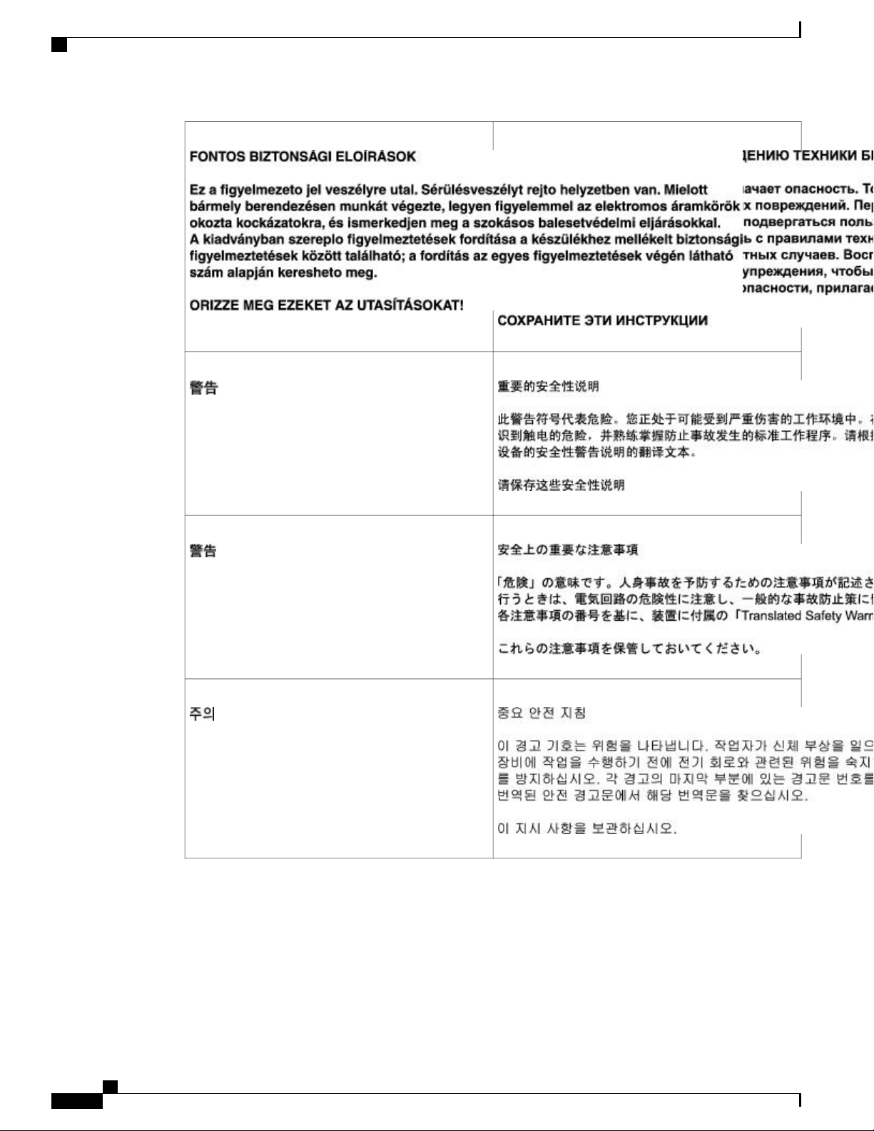
Warning Definition
Safety Warnings and Cautions
Warning
Waarschuwing
IMPORTANT SAFETY INSTRUCTIONS
This warning symbol means danger. You are in a
situation that could cause bodily injury. Before you
work on any equipment, be aware of the hazards
involved with electrical circuitry and be familiar with
standard practices for preventing accidents. Use the
statement number provided at the end of each warning
to locate its translation in the translated safety
warnings that accompanied this device. Statement
1071
SAVE THESE INSTRUCTIONS
BELANGRIJKE VEILIGHEIDSINSTRUCTIES
Dit waarschuwingssymbool betekent gevaar. U
verkeert in een situatie die lichamelijk letsel kan
veroorzaken. Voordat u aan enige apparatuur gaat
werken, dient u zich bewust te zijn van de bij
elektrische schakelingen betrokken risico's en dient
u op de hoogte te zijn van de standaard praktijken om
ongelukken te voorkomen. Gebruik het nummer van
de verklaring onderaan de waarschuwing als u een
vertaling van de waarschuwing die bij het apparaat
wordt geleverd, wilt raadplegen.
BEWAAR DEZE INSTRUCTIES
Varoitus
TÄRKEITÄ TURVALLISUUSOHJEITA
Tämä varoitusmerkki merkitsee vaaraa. Tilanne voi
aiheuttaa ruumiillisia vammoja. Ennen kuin käsittelet
laitteistoa, huomioi sähköpiirien käsittelemiseen
liittyvät riskit ja tutustu onnettomuuksien yleisiin
ehkäisytapoihin. Turvallisuusvaroitusten käännökset
löytyvät laitteen mukana toimitettujen käännettyjen
turvallisuusvaroitusten joukosta varoitusten lopussa
näkyvien lausuntonumeroiden avulla.
SÄILYTÄ NÄMÄ OHJEET
Cisco ASR 1000 Series Router Hardware Installation Guide
xxvii
Page 28

Warning Definition
Preface
Attention
Warnung
IMPORTANTESINFORMATIONSDE SÉCURITÉ
Ce symbole d'avertissement indique un danger. Vous
vous trouvez dans une situation pouvant entraîner des
blessures ou des dommages corporels. Avant de
travailler sur un équipement, soyez conscient des
dangers liés aux circuits électriques et
familiarisez-vous avec les procédures couramment
utilisées pour éviter les accidents. Pour prendre
connaissance des traductions des avertissements
figurant dans les consignes de sécurité traduites qui
accompagnent cet appareil, référez-vous au numéro
de l'instruction situé à la fin de chaque avertissement.
CONSERVEZ CES INFORMATIONS
WICHTIGE SICHERHEITSHINWEISE
Dieses Warnsymbol bedeutet Gefahr. Sie befinden
sich in einer Situation, die zu Verletzungen führen
kann. Machen Sie sich vor der Arbeit mit Geräten mit
den Gefahren elektrischer Schaltungen und den
üblichen Verfahren zur Vorbeugung vor Unfällen
vertraut. Suchen Sie mit der am Ende jeder Warnung
angegebenen Anweisungsnummer nach der jeweiligen
Übersetzung in den übersetzten Sicherheitshinweisen,
die zusammen mit diesem Gerät ausgeliefert wurden.
BEWAHREN SIE DIESE HINWEISE GUT AUF.
Avvertenza
Advarsel
IMPORTANTI ISTRUZIONI SULLA SICUREZZA
Questo simbolo di avvertenza indica un pericolo. La
situazione potrebbe causare infortuni alle persone.
Prima di intervenire su qualsiasi apparecchiatura,
occorre essere al corrente dei pericoli relativi ai
circuiti elettrici e conoscere le procedure standard per
la prevenzione di incidenti. Utilizzare il numero di
istruzione presente alla fine di ciascuna avvertenza
per individuare le traduzioni delle avvertenze riportate
in questo documento.
CONSERVARE QUESTE ISTRUZIONI
VIKTIGE SIKKERHETSINSTRUKSJONER
Dette advarselssymbolet betyr fare. Du er i en
situasjon som kan føre til skade på person. Før du
begynner å arbeide med noe av utstyret, må du være
oppmerksom på farene forbundet med elektriske
kretser, og kjenne til standardprosedyrer for å
forhindre ulykker. Bruk nummeret i slutten av hver
advarsel for å finne oversettelsen i de oversatte
sikkerhetsadvarslene som fulgte med denne enheten.
TA VARE PÅ DISSE INSTRUKSJONENE
xxviii
Cisco ASR 1000 Series Router Hardware Installation Guide
Page 29

Preface
Warning Definition
Aviso
¡Advertencia!
INSTRUÇÕES IMPORTANTESDE SEGURANÇA
Este símbolo de aviso significa perigo. Você está em
uma situação que poderá ser causadora de lesões
corporais. Antes de iniciar a utilização de qualquer
equipamento, tenha conhecimento dos perigos
envolvidos no manuseio de circuitos elétricos e
familiarize-se com as práticas habituais de prevenção
de acidentes. Utilize o número da instrução fornecido
ao final de cada aviso para localizar sua tradução nos
avisos de segurança traduzidos que acompanham este
dispositivo.
GUARDE ESTAS INSTRUÇÕES
INSTRUCCIONES IMPORTANTES DE
SEGURIDAD
Este símbolo de aviso indica peligro. Existe riesgo
para su integridad física. Antes de manipular cualquier
equipo, considere los riesgos de la corriente eléctrica
y familiarícese con los procedimientos estándar de
prevención de accidentes. Al final de cada advertencia
encontrará el número que le ayudará a encontrar el
texto traducido en el apartado de traducciones que
acompaña a este dispositivo.
GUARDE ESTAS INSTRUCCIONES
Varning!
VIKTIGA SÄKERHETSANVISNINGAR
Denna varningssignal signalerar fara. Du befinner dig
i en situation som kan leda till personskada. Innan du
utför arbete på någon utrustning måste du vara
medveten om farorna med elkretsar och känna till
vanliga förfaranden för att förebygga olyckor. Använd
det nummer som finns i slutet av varje varning för att
hitta dess översättning i de översatta
säkerhetsvarningar som medföljer denna anordning.
SPARA DESSA ANVISNINGAR
Cisco ASR 1000 Series Router Hardware Installation Guide
xxix
Page 30
Warning Definition
Preface
xxx
Cisco ASR 1000 Series Router Hardware Installation Guide
Page 31

Preface
Warning Definition
Aviso
Advarsel
INSTRUÇÕES IMPORTANTESDE SEGURANÇA
Este símbolo de aviso significa perigo. Você se
encontra em uma situação em que há risco de lesões
corporais. Antes de trabalhar com qualquer
equipamento, esteja ciente dos riscos que envolvem
os circuitos elétricos e familiarize-se com as práticas
padrão de prevenção de acidentes. Use o número da
declaração fornecido ao final de cada aviso para
localizar sua tradução nos avisos de segurança
traduzidos que acompanham o dispositivo.
GUARDE ESTAS INSTRUÇÕES
VIGTIGE SIKKERHEDSANVISNINGER
Dette advarselssymbol betyder fare. Du befinder dig
i en situation med risiko for legemesbeskadigelse.
Før du begynder arbejde på udstyr, skal du være
opmærksom på de involverede risici, der er ved
elektriske kredsløb, og du skal sætte dig ind i
standardprocedurer til undgåelse af ulykker. Brug
erklæringsnummeret efter hver advarsel for at finde
oversættelsen i de oversatte advarsler, der fulgte med
denne enhed.
GEM DISSE ANVISNINGER
Cisco ASR 1000 Series Router Hardware Installation Guide
xxxi
Page 32

Warning Definition
Preface
xxxii
Cisco ASR 1000 Series Router Hardware Installation Guide
Page 33

Preface
Related Documentation
Warning Only trained and qualified personnel should be allowed to install, replace, or service this equipment.
Statement 1030
Warning This unit is intended for installation in restricted access areas. A restricted access area can be accessed
only through the use of a special tool, lock and key, or other means of security. Use when a product has an
accessible HAZ/V circuits or a DC supply that is not provided with a field wiring cover. Statement 1017
Related Documentation
Your Cisco ASR 1000 Series Routers and the Cisco IOS software running on it contain extensive features
and functionality, which are documented in the following resources:
All documentation related to the Cisco ASR 1000 Series Routers is listed in the online Cisco ASR 1000
•
Series Aggregation Services Routers Documentation Roadmap . Information in this master index includes
troubleshooting tools and documentation, regulatory compliance and safety information, and installation
and replacement information. Also see the Cisco ASR 1000 Series Port Adapter Documentation Roadmap
for specific shared port adapters supported on the Cisco ASR 1000 Series Routers.
Some of the Cisco ASR 1000 Series Routers documentation that is listed on the Cisco ASR 1000 Series
Aggregation Services Routers Documentation Roadmap includes:
Quick Start Guides for the Cisco ASR 1000 Series Routers. These guides provide quick reference
•
◦
information about chassis or parts installation procedures.
Cisco ASR 1000 Series Router Hardware Installation Guide
xxxiii
Page 34

Obtaining Documentation and Submitting a Service Request
The Cisco ASR 1000 Series Aggregation Services Routers Troubleshooting document contains
◦
information to help you troubleshoot problems with the Cisco ASR 1000 Series Routers.
The Regulatory Compliance and Safety Information for Cisco ASR 1000 Series Aggregation
◦
Services Routers document provides international agency compliance, safety, and statutory
information for wide-area network (WAN) interfaces for the Cisco ASR 1000 Series Routers.
Cisco ASR 1000 Series shared port adapter documentation.
◦
Cisco IOS software documentation contains Cisco IOS software configuration information and support.
•
See the modular configuration and modular command reference publications in the set that corresponds
to the software release installed on your Cisco hardware.
To check the minimum software requirements of Cisco IOS software with the hardware installed on
•
your router, Cisco maintains the Software Advisor tool on Cisco.com. This tool does not verify whether
modules within a system are compatible, but it does provide the minimum IOS requirements for individual
hardware modules or components.
Preface
Access to this tool is limited to users with Cisco.com login accounts.Note
Obtaining Documentation and Submitting a Service Request
For information on obtaining documentation, submitting a service request, and gathering additional information,
see the monthly What’s New in Cisco Product Documentation , which also lists all new and revised Cisco
technical documentation, at:
http://www.cisco.com/en/US/docs/general/whatsnew/whatsnew.html
Subscribe to the What’s New in Cisco Product Documentation as a Really Simple Syndication (RSS) feed
and set content to be delivered directly to your desktop using a reader application. The RSS feeds are a free
service and Cisco currently supports RSS version 2.0.
xxxiv
Cisco ASR 1000 Series Router Hardware Installation Guide
Page 35

CHAPTER 1
Cisco ASR 1000 Series Routers Hardware Overview
The Cisco ASR 1000 Series Aggregation Services Routers are the next generation midrange router products.
The system is based on Cisco QuantumFlow Processor technology using a family of Cisco-developed
processors.
The Cisco ASR 1000 Series Routers target both enterprise and service provider applications but with higher
performance and improved availability. Applications covered by Cisco ASR 1000 Series Routers are:
• Enterprise applications—Intended as the mid-size aggregation and gateway router typically residing
in a regional or large branch office:
WAN aggregation at Cisco Enterprise core
◦
Internet gateway
◦
Branch or regional office aggregation
◦
Remote access aggregation
◦
• Service provider applications—Intended as the low-end service provider edge and broadband aggregation
device with similar throughput:
High-end customer premises equipment (CPE) for business-quality Internet access
◦
Service provider leased line aggregation
◦
Provider edge (PE) and high-end customer edge (CE) for Layer 2 VPN or Layer 3 VPN services
◦
◦ Broadband aggregation—PPPoE/PPPoA aggregation and Service Selection Gateway (SSG)
Low-end Ethernet aggregation
◦
This chapter provides an overview of the Cisco ASR 1000 Series Routers and contains the following sections:
Cisco ASR 1000 Series Routers, page 2
•
Cisco ASR 1000 Series Router Features, page 3
•
Cisco ASR 1000 Series Routers Compatibility Information, page 5
•
Cisco ASR 1000 Series Router Configurations, page 7
•
Cisco ASR 1000 Series Router Hardware Installation Guide
1
Page 36

Cisco ASR 1000 Series Routers
Field-Replaceable Units, page 7
•
Functional Overview, page 8
•
Cisco Product Identification Standard, page 17
•
Cisco ASR 1000 Series Routers
The Cisco ASR 1000 Series Aggregation Services Routers are the next generation Cisco midrange router
products. The Cisco ASR 1000 Series Aggregation Services Routers use an innovative and powerful hardware
processor technology known as the Cisco QuantumFlow Processor. The following are the Cisco ASR 1000
Series Routers:
The Cisco ASR 1006 Router is a 12-SPA, 6-rack-unit (RU), hardware-redundant chassis with two
•
Embedded Services Processor (ESP) slots, two Route Processor (RP) slots, and three SIP slots.
The Cisco ASR 1004 Router is an 8-SPA, four rack-unit (RU) chassis with one ESP slot, one RP slot,
•
and two SIP slots.
Cisco ASR 1000 Series Routers Hardware Overview
The Cisco ASR 1002 Router is a 3-SPA, 2-RU chassis with one embedded services processor slot that
•
comes with the route processor, Cisco ASR 1000 Series Shared Port Adapter Interface Processor (SIP),
and 4 Gigabit Ethernet ports built in. For more information about the type of connectors and cables used
by the 4-port Gigabit Ethernet built-in SPA, the Cisco ASR 1000 Series Aggregation Services Routers
SIP and SPA Hardware Installation Guide .
The Cisco ASR 1002-F Router is a one half-height SPA, 2-RU chassis. The embedded services processor,
•
route processor, and SPA interface processor (SIP) are integrated with the chassis. In addition, 4 Gigabit
Ethernet ports are built into the chassis.
The Cisco ASR 1013 Router is a 24 half-height shared port adapters, 13-RU chassis that can hold 6 SIPs
•
and provides superslots (more height and power) for the Cisco ASR1000-RP2s and Cisco ASR1000-ESPs.
The Cisco ASR 1013 Router is designed with two zones (Zone 1 and Zone 0) for redundancy and
superslot spacing. The Cisco ASR 1013 router has four 40G slots and two 100G slots.
The Cisco ASR 1001 Router is a one rack-unit chassis that offers a compact form factor router that
•
satisfies customer demands such as low power consumption and decreased usage of rack space. The
Cisco ASR 1001 Router has the route processor, embedded services processor, and SIP integrated within
the chassis with one half-height SPA slot.
The Cisco ASR 1002-X Router is a 3-SPA, 2-RU chassis. The embedded services processor and route
•
processor of this router are integrated in the chassis. There are six small form factor pluggable (SFP)
Gigabit Ethernet ports. Depending on the Cisco software license that you install, the router can provide
a forwarding bandwidth of 5 Gbps, 10 Gbps, 20 Gbps, or 36 Gbps.
For the single-route-processor Cisco ASR 1000 platforms (Cisco ASR 1002, Cisco ASR 1002-F, Cisco ASR
1002-X and Cisco ASR 1004), the route processor has a dual Cisco IOS Software option that allows these
routers to use Cisco IOS software redundancy, Cisco high-availability features, and Nonstop Forwarding
(NSF). Single-route-processor Cisco ASR 1000 platforms do not support ISSU upgrade or downgrade. Instead
sub-package software upgrade is supported only if the router is running in sub-package mode.
The Software Redundancy feature requires the router to have 8 GB of DRAM memory.Note
Cisco ASR 1000 Series Router Hardware Installation Guide
2
Page 37

Cisco ASR 1000 Series Routers Hardware Overview
The Cisco ASR 1000 Series Routers run Cisco IOS XE Software and introduce a distributed software
architecture that moves many operating system responsibilities out of the IOS process. In this architecture,
Cisco IOS, which previously was responsible for almost all of the internal software processes, now runs as
one of many Cisco IOS XE processes while allowing other Cisco IOS XE processes to share responsibility
for running the router.
The Cisco ASR 1000 Series Routers use the powerful Cisco QuantumFlow Processor which provides
performance and resiliency for network processors.
The Cisco ASR 1000 Series Routers deliver multiple services embedded in the Cisco QuantumFlow Processor.
The services supported on the Cisco Packet QuantumFlow Processor include security services (for example,
encryption and firewall), quality of service (QoS), Network Based Application Recognition (NBAR), broadband
aggregation, and session border controller, among others.
Cisco ASR 1000 Series Router Features
The Cisco ASR 1000 Series Aggregation Services routers use different field replaceable units:
• Cisco ASR 1000 Series route processor— Cisco ASR1000-RP1, ASR1000-RP2
Cisco ASR 1000 Series Router Features
Note
Cisco ASR 1000 Series embedded services processors (ESPs):
•
Cisco ASR1000-ESP5
◦
Cisco ASR1000-ESP10
◦
Cisco ASR1000-ESP20
◦
Integrated Cisco ASR1002-ESP-F
◦
Cisco ASR1000-ESP40
◦
Cisco ASR1000-ESP100
◦
Cisco ASR1000-ESP200
◦
See xref Chapter 3, “Cisco ASR 1000 Series Routers Embedded Services Processors” for detailed
information about Cisco ESPs.
Cisco ASR 1000 SPA Interface Processors (SIPs):
•
Cisco ASR1000-SIP10
◦
Cisco ASR1002-SIP10-F
◦
Cisco ASR1000-SIP-40
◦
Note
See xref Chapter 4, “Cisco ASR 1000 Series Router SPA Interface Processors (SIPs)” for detailed
information about Cisco SIPs.
Cisco ASR 1000 Series Routers provide the following features:
Cisco ASR 1000 Series Router Hardware Installation Guide
3
Page 38

Cisco ASR 1000 Series Router Features
Online insertion and removal (OIR) capability
•
Route processor and embedded services processor redundancy in the Cisco ASR 1000 Series Routers
•
(Cisco ASR 1013 Router and Cisco ASR 1006 Router)
Control processor for ASR 1000 Series SPA Interface Processor
•
Control processor for embedded services processors (Cisco ASR1000-ESP5, Cisco ASR1000-ESP10,
•
Cisco ASR1000-ESP20, integrated Cisco ASR1002-ESP-F, Cisco ASR1000-ESP40, Cisco
ASR1000-ESP100, and Cisco ASR1000-ESP200)
10 Gbps and 20 Gbps interconnect between Cisco QuantumFlow Processor with redundant Cisco ASR
•
1000 Series ESP to mirror data for stateful features
Power supply redundancy
•
Environmental monitoring and reporting functions
•
Family of routers using common hardware and software architecture
•
Centralized forwarding design (all network traffic passes through one engine)
•
• Front-to-back airflow—Allows you to mount the router from either front or back into 19-inch equipment
rack
Cisco ASR 1000 Series Routers Hardware Overview
Supports half-height shared port adapters (HHSPAs) and full-height shared port adapters (FHSPAs)
•
The Cisco ASR 1001 Router does not support full-height SPAs.Note
Single midplane design (all connectors on one interface midplane)
•
• One 10/100/1000-Mbps Ethernet Management port—To be used only as a management port; not to be
used as an Ethernet interface port
Both quarter-rate (87.5 MHz) and full-rate (350 MHz) shared port adapter operation
•
The Cisco QuantumFlow Processor processing provides:
Architecture to address Cisco ASR 1000 Series router performance, cost, power, and feature velocity
•
Next Generation forwarding and queuing subsystems for Cisco routers to provide data path acceleration.
•
The Cisco ASR 1000 Series route processor system performs the following system management functions:
Sending and receiving routing protocol updates
•
Managing tables, caches, and buffers
•
Monitoring interface and environmental status
•
Providing Simple Network Management Protocol (SNMP) management through the console and Telnet
•
interface
Accounting for and switching of data traffic
•
Booting and reloading images
•
Cisco ASR 1000 Series Router Hardware Installation Guide
4
Page 39

Cisco ASR 1000 Series Routers Hardware Overview
Cisco ASR 1000 Series Routers Compatibility Information
Cisco ASR 1000 Series Routers Compatibility Information
The following table lists the Cisco ASR 1000 Series Routers configurations. It shows the combination of
chassis, Cisco ASR1000-ESP, and Cisco ASR1000-SIP supported on the Cisco ASR 1000 Series Routers.
Table 1: Cisco ASR 1000 Series Routers Component Compatibility
ASR 1013ASR 1006ASR 1004
SIP40SIP10*SIP40SIP10SIP40SIP10Embedded
Services
Processor
NoNoYesYesYesYesESP10
NoNoYesYesYesYesESP20
YesYes*YesYesYesYesESP40
Note
The Cisco ASR 1001 Router supports Cisco ASR1000-ESP2.5 up to Cisco ASR1000-ESP5. The Cisco
ASR 1002 Router, Cisco ASR 1002-F Router, and Cisco ASR 1002-X Router do not support Cisco
ASR1000-ESP20, Cisco ASR1000-ESP40, Cisco ASR1000-ESP100, or Cisco ASR1000-RP2. Cisco
ASR1000-ESP100 can be installed only on Cisco ASR 1006 and Cisco ASR 1013 routers. Cisco
ASR1000-ESP200 can be installed only on Cisco ASR 1013 routers.
Hardware Compatibility
The following table lists the Cisco ASR 1000 Series Routers that support and are compatible with Cisco
hardware products.
Table 2: Cisco ASR 1000 Series Routers and Component Compatibility and Support Matrix
Hardware
Component
Cisco ASR 1013
Router
Cisco ASR 1006
Router
Cisco ASR 1004
Router
Cisco ASR 1002
Router and Cisco
ASR 1002-F
Router
Cisco ASR 1001
Router
YesYesYesYesNoNoESP100
YesYesNoNoNoNoESP200
Cisco ASR 1002-X
Router
Not applicableNot applicableSupportedNot supportedNot compatibleNot compatibleASR1000-ESP5
Not applicableNot applicableSupportedSupportedSupportedNot compatibleASR1000-ESP10
Cisco ASR 1000 Series Router Hardware Installation Guide
5
Page 40

Hardware Compatibility
Cisco ASR 1000 Series Routers Hardware Overview
Hardware
Component
ASR1000 PEMs
Cisco ASR 1013
Router
ASR 1013 PEM
supported
Cisco ASR 1006
Router
ASR 1013 PEM
supported
ASR 1006 PEM
supported
Cisco ASR 1004
Router
ASR1004 PEM
supported
Cisco ASR 1002
Router and Cisco
ASR 1002-F
Router
ASR 1002 PEM
supported
Cisco ASR 1001
Router
Supported with
its own AC and
DC power
supplies
Cisco ASR 1002-X
Router
Not applicableNot applicableNot compatibleSupportedSupportedNot supportedASR1000-ESP20
Not applicableNot applicableNot compatibleSupportedSupportedSupportedASR1000-ESP40
Not applicableNot applicableNot compatibleNot compatibleSupportedSupportedASR1000-ESP100
Not compatibleNot compatibleNot compatibleNot compatibleNot compatibleSupportedASR1000-ESP200
Not applicableNot applicableNot applicableSupportedSupportedNot compatibleASR1000-RP1
Not applicableNot applicableNot applicableSupportedSupportedSupportedASR1000-RP2
Not applicableNot applicableNot applicableSupportedSupportedSupportedASR1000-SIP10
Not applicableNot applicableNot applicableSupportedSupportedSupportedASR1000-SIP40
ASR 1002 PEM
supported
The following is the outcome of upgrades performed using incompatible combinations of hardware components:
The embedded services processor card is disabled and an error message is generated in either of the
•
following scenarios:
Cisco ASR1000-ESP20, Cisco ASR1000-ESP40, or Cisco ASR1000-ESP100 is inserted in the
◦
Cisco ASR 1002 Router.
Cisco ASR1000-ESP5 is inserted into Cisco ASR 1004 Router, Cisco ASR 1006 Router, or Cisco
◦
ASR 1013 Router.
The Complex Programmable Logic Device (CPLD) field programmable upgrade for Cisco
•
ASR1000-SIP10 cannot be performed in slot 5. Cisco ASR1000-SIP10 can be upgraded only in any one
of the slots from slots 0 to 4.
If Cisco ASR1000-RP1 is inserted into Cisco ASR 1013 Router, the card is disabled and an error message
•
is generated
The Cisco ASR 1013 Router supports only the following components:
Cisco ASR1000-RP2
•
Cisco ASR1000-ESP40 or Cisco ASR1000-ESP200
•
Cisco ASR1000-SIP10 or Cisco ASR1000-SIP40
•
Cisco ASR 1000 Series Router Hardware Installation Guide
6
Page 41

Cisco ASR 1000 Series Routers Hardware Overview
Cisco ASR 1000 Series Router Configurations
Existing Cisco ASR1000-RP2 and Cisco ASR1000-SIP10 cannot be used as is in the Cisco ASR 1013 Router.
These two components must be upgraded to support Cisco IOS XE Release 3.1S on the Cisco ASR 1013
Router.
Cisco ASR 1000 Series Router Configurations
The Cisco ASR 1000 Series Routers are available in different packaging configurations. Some of the chassis
configurations are modular with separate field-replaceable units (FRUs) for the Cisco ASR 1000 Series Route
Processors, the Cisco ASR 1000 Series Embedded Services Processors, and the shared port adapters.
All FRUs (Cisco ASR 1000 Series Route Processor 1, Cisco ASR 1000 Series Embedded Services Processor,
and SPAs) are designed to work in the different chassis models. The power supplies and fan modules are
chassis specific. The SPAs are supported in all chassis configurations although there are SPA restrictions in
the Cisco ASR 1002 Router and the Cisco ASR 1002-F Router.
The following table lists the Cisco ASR 1000 Series Router configurations. In this table, HH is half height
and FH is full height.
Table 3: Cisco ASR 1000 Series Router Product Family
Chassis
Cisco ASR 1001
1002-F
1002-X
Number of ESP
Slots
Built-in ESP 2.5
Gbps/5 Gbps
1Cisco ASR 1002
1Cisco ASR
1Cisco ASR
Maximum SPAs
Supported
1 HH
Built-in ports 4
x 1GE SFP
3 HH (1 built-in
4x1GE)
1 HH (1 built-in
4x1 GE)
built-in 6x1 GE
Number of RP
Slots
2.13GHz dual
core Intel Xeon
CPU
1 integrated
(RP1)
1 integrated
(RP1)
Number of SIP
Slots
Fixed, SIP10One built-in
(SIP10)
(SIP10)
1 integrated1 integrated3 HH and 1
Maximum
Bandwidth
Up to 5 Gbps
(with software
license)
Up to 200 Gbps62 superslots24 HH2 superslotsCisco ASR 1013
Up to 100 Gbps3212 HH2Cisco ASR 1006
Up to 40 Gbps218 HH1Cisco ASR 1004
Up to 10 Gbps1 integrated
Up to 2.5 Gbps1 integrated
Up to 36 Gbps
(with software
license)
Field-Replaceable Units
The Cisco ASR 1000 Series routers are easy to service; many of their major components are field-replaceable
units (FRUs). The following are the Cisco ASR 1000 Series Router FRUs:
Cisco ASR 1000 Series Router Hardware Installation Guide
7
Page 42

Functional Overview
Cisco ASR 1000 Series Routers Hardware Overview
Cisco ASR 1000 Series route processors: RP1 and RP2
•
Cisco ASR 1000 Series embedded services processors: Cisco ASR1000-ESP5, Cisco ASR1000-ESP10,
•
Cisco ASR1000-ESP20, Cisco ASR1000-ESP40, Cisco ASR1000-ESP100, and Cisco ASR1000-ESP200.
Shared port adapters
•
Cisco ASR 1000 Series shared port adapter interface processors (SIPs)
•
Cisco ASR 1000 Series RP1 internal hard drive
•
Cisco ASR 1000 Series RP1 DIMM memory module (Note that the integrated Cisco ASR1000-RP1 on
•
the Cisco ASR 1002 Router DIMM memory module is not field-replaceable.)
USB flash token memory stick
•
AC and DC power supplies
•
• Bracket kit—Custom cable-management brackets are mounted to each rack-mount bracket to provide
cable management to both sides of the chassis (parallel with card orientation). These brackets are
screw-mounted to the rack brackets to enable easy installation and removal. There is a rack-mount
bracket for each chassis:
Note
For the Cisco ASR 1006 Router, the cable-management brackets contain five independent
◦
cable-management U features to provide cable dressing for each card module slot. For SIPs, these
brackets work in tandem with SPA product feature cable management to allow installation and
removal of adjacent cards without having to remove cables.
For the Cisco ASR 1004 Router, the cable-management brackets contain three independent
◦
cable-management U features to provide cable dressing for each card module slot. For SIPs, these
brackets work in tandem with SPA product feature cable management to allow installation and
removal of adjacent cards without having to remove cables.
For the Cisco ASR 1002 Router, the cable-management brackets contains one independent
◦
cable-management U feature to provide cable dressing for each card module slot. These brackets
work in tandem with SPA product feature cable management to allow installation and removal of
adjacent cards without having to remove cables.
The Cisco ASR 1002-F Router and Cisco ASR 1002-X Router use the same accessories as the Cisco ASR
1002 Router.
For the Cisco ASR 1013 Router, the cable-management brackets contain four independent
•
◦
cable-management U features to provide cable dressing for modules. There are two brackets with
four U-feature hooks for each side of the chassis.
For the Cisco ASR 1001 Router, the cable-management bracket contains one independent
◦
cable-management U feature to provide cable dressing for each card module slot.
Functional Overview
This section contains the following topics:
Cisco ASR 1000 Series Router Hardware Installation Guide
8
Page 43

Cisco ASR 1000 Series Routers Hardware Overview
Chassis Slot and Logical Interface Numbering
The Cisco ASR 1000 Series Routers have a slot numbering system located on both sides of the card module
location. The chassis slots are physically numbered from zero starting at the bottom of the chassis. This section
describes the slot numbering for the Cisco ASR 1000 Series Routers:
Cisco ASR 1000 Series SPA Interface Processor (SIP) subslots begin their numbering with “0” and have a
horizontal orientation. The SIP subslot numbering is indicated by a small numeric label beside the subslot on
the faceplate. Some commands allow you to display information about the SPA itself, such as show idprom
module and show hw-module subslot. These commands require you to specify both the physical location
of the SIP and SPA in the format, Slot/Subslot, where:
• Slot—Specifies the chassis slot number in the Cisco ASR 1000 Series Routers where the SIP is installed.
• Subslot—Specifies a subslot of the SIP where the SPA is installed.
• Superslots (power zone 0 and power zone 1)—Specifies the Cisco ASR 1013 Router slot spacing divided
into zones.
Chassis Slot and Logical Interface Numbering
See the router-specific chapter for chassis slot numbering and naming descriptions.Note
MAC Address Information
The Media Access Control (MAC) or hardware address is a standardized data link layer address that is required
for certain network interface types. These addresses are specific and unique to each port and are not used by
other devices in the network. The Cisco ASR 1000 Series Routers assign and control the MAC addresses of
its shared port adapters.
You can identify shared port adapter slots by using software commands. To display information about:
All shared port adapter slots, use the show interfaces command.
•
A specific shared port adapter slot, use the show interfaces command with the shared port adapter type
•
and slot number in the format show interfaces port-adapter-type slot-number/port-number.
Note
If you abbreviate the command (sh int) and do not specify shared port adapter type and slot number (or
arguments), the system interprets the command as show interfaces and displays the status of all shared
port adapters and ports.
The MAC addresses are assigned to the slots in sequence. For example, in the Cisco ASR 1006 Router, the
first address is assigned to slot 0 and the last address is assigned to slot 6. The actual MAC address assignment
is 16 MAC addresses per SPA slot for half-height SPAs and 64 per SPA slot for full-height SPAs. Also, the
Cisco ASR 1000 Series RP1 RP Management Ethernet port is assigned one MAC address from the end of the
pool and for the Cisco ASR 1006 Router with two Cisco ASR 1000 RP1s, each ASR10000 RP1 is assigned
one MAC address.
Using this address scheme, you can remove shared port adapters and insert them into other routers without
causing the MAC addresses to move around the network or be assigned to multiple devices.
Cisco ASR 1000 Series Router Hardware Installation Guide
9
Page 44

Online Insertion and Removal
If the MAC addresses were stored on each shared port adapter, online insertion and removal would not function
because you could never replace one shared port adapter with an identical one; the MAC addresses would
always be different. Also, each time a shared port adapter was replaced, other devices on the network would
have to update their data structures with the new address. If the other devices did not update quickly enough,
the same MAC address could appear in more than one device at the same time.
Cisco ASR 1000 Series Routers Hardware Overview
Note
Storing the MAC addresses for every slot in one central location means the addresses stay with the memory
device on which they are stored.
Online Insertion and Removal
In the modular chassis configurations, most Cisco ASR 1000 Series Router field-replaceable units (FRUs)
support online insertion and removal (OIR). However, the removal of critical non-redundant FRUs will result
in service interruption.
Note
As you disengage the shared port adapter from the router, online insertion and removal (OIR)
administratively shuts down all active interfaces in the shared port adapter.
Online insertion and removal (OIR) feature allows you to install and replace shared port adapters while the
router is operating; you do not need to notify the software or shut down the system power, although you should
not run traffic through the shared port adapter you are removing while it is being removed. Online insertion
and removal is a method that is seamless to end users on the network, maintains all routing information, and
preserves sessions.
All SPA OIR events are independent of one another. An OIR event of a single SPA does not affect the other
SPAs in that ASR1000-SIP10 or any other system function.
The following items describe the OIR differences between the Cisco ASR 1002 Router, the Cisco ASR 1002-F
Router, and the Cisco ASR 1002-X Router:
The Cisco ASR 1002 Router supports the integrated Cisco ASR1000-RP1, which is a combined route
•
processor and carrier card that are not field-replaceable units. The Cisco ASR1000-ESP5 or
ASR1000-ESP10 are field-replaceable units.
The Cisco ASR 1002-F Router supports an integrated route processor Cisco ASR1002-RP1 and an
•
integrated embedded services processor Cisco ASR1000-ESP-F, which are not field-replaceable. The
Cisco ASR1002-SIP10-F module is not removable; but the one half-height SPA is a field-replaceable
unit.
The Cisco ASR 1002-X Router supports an integrated route processor (Cisco ASR1002-RP2) and an
•
integrated embedded services processor. Both these components are not field-replaceable. The router
has a built-in 6x1GE SPA that occupies the SPA Bay 0. In addition, there are three half-height SPA
bays for field-replaceable SPAs.
The following is a functional description of OIR for background information only; for specific procedures
for installing and replacing a shared port adapter in Cisco ASR 1000 Series Routers, refer to the online
configuration note for each shared port adapter.
Cisco ASR 1000 Series Router Hardware Installation Guide
10
Page 45

Cisco ASR 1000 Series Routers Hardware Overview
Environmental Monitoring and Reporting Functions
When you remove or insert a shared port adapter in a Cisco ASR 1000 Series Router, the Control Processor
notifies the Cisco ASR1000-RP1, which in turn notifies the forwarding engine control processor (FECP), and
then performs the following steps:
Rapidly scans the midplane for configuration changes.
•
Initializes all newly inserted shared port adapters, noting any removed interfaces and placing them in
•
the administratively shutdown state.
Brings all previously configured interfaces on the shared port adapter back to the state they were in when
•
they were removed. Any newly inserted interfaces are put in the administratively shutdown state, as if
they were present (but not configured) at boot time. If a similar shared port adapter type is reinserted
into a slot, its ports are configured and brought online up to the port count of the original SPA.
Environmental Monitoring and Reporting Functions
Environmental monitoring and reporting functions allow you to maintain normal system operation by identifying
and resolving adverse conditions prior to loss of operation.
Caution
To prevent overheating the chassis, ensure that your system is drawing cool inlet air. Over temperature
conditions can occur if the system is drawing in the exhaust air of other equipment. Ensure adequate
clearance around the sides of the chassis so that cooling air can flow through the chassis interior unimpeded
and exhaust air exits the chassis and is not drawn into the inlet vent of another device.
Environmental Monitoring
The environmental monitoring functions use sensors to monitor the temperature of the cooling air as it moves
through the chassis.
The local power supplies provide the ability to monitor:
Input and output voltage
•
Output current
•
Outlet temperature
•
The Cisco ASR 1000 Series Routers are expected to meet the following environmental operating conditions:
Operating Temperature Nominal: 5° to 40°C
•
• Operating Temperature Short Term: –5° to +55°C (not applicable to the Cisco ASR 1001 Router)
Operating Humidity Nominal: 5% to 85% noncondensing
•
Operating Humidity Short Term: 5% to 90% noncondensing (not applicable to the Cisco ASR 1001
•
Router)
Operating Altitude: 198 to 13,200 feet (60 to 4000 meters)
•
• DC Input Range: –40.5 to –72 VDC
AC Input Range: 85 to 264 VAC
•
Cisco ASR 1000 Series Router Hardware Installation Guide
11
Page 46

Environmental Monitoring and Reporting Functions
If the air temperature exceeds a defined threshold, the system controller displays warning messages on the
console terminal, and if the temperature exceeds the shutdown threshold, the system controller shuts down
the system.
In addition, the power supplies monitor internal power supply temperatures and voltages. A power supply is
either within tolerance (normal) or out of tolerance (critical). If an internal power supply temperature or voltage
reaches a critical level, the power supply shuts down without any interaction with the system processor.
The environmental monitoring functions use the following levels of status conditions to monitor the system:
• Normal—All monitored parameters are within normal tolerances.
• Warning—The system has exceeded a specified threshold. The system continues to operate, but operator
action is recommended to bring the system back to a normal state.
• Critical—An out-of-tolerance temperature or voltage condition exists. The system continues to operate;
however, the system is approaching shutdown. Immediate operator action is required.
• Shutdown—The processor has detected a temperature condition that could result in physical damage to
system components and has disabled DC power to all internal components. This condition requires
immediate operator action. All DC power remains disabled until you toggle the power switch. Before
any shutdown, the system logs the status of monitored parameters in NVRAM so you can retrieve it
later to help determine the cause of the problem.
Cisco ASR 1000 Series Routers Hardware Overview
• Power supply shutdown—The power supply detected an internal out-of-tolerance overvoltage, overcurrent,
or temperature condition and shut itself down. All DC power remains disabled until you toggle the power
switch.
Fan Failures
When the system power is on, all fans should be operational. The system continues to operate if a fan fails.
When a fan fails, the system displays the following message:
router: 00:03:46:%ENVM-3-BLOWER:Fan 2 may have failed
If the air temperature exceeds a defined threshold, the system controller displays warning messages on the
console terminal, and if the temperature exceeds the shutdown threshold, the system controller shuts down
the system.
If the system does shut down because the temperature exceeded the shutdown threshold, the system displays
the following message on the console screen and in the environment display when the system restarts:
Queued messages:
%ENVM-1-SHUTDOWN: Environmental Monitor initiated shutdown
Reporting Functions
The chassis manager on the forwarding engine control processor manages the local resources of the forwarding
processor. It manages the ESI (Enhanced Serdes Interconnect) which are the datapath links on the midplane
connecting the Cisco ASR 1000 Series RP1s, SIPs, and standby ESP modules to the active Cisco ASR 1000
Series Embedded Services Processor. It communicates with the chassis manager on the Cisco ASR 1000
Series Route Processor 1 to report the status and health, including detected hardware failures, ESI status,
software process status, and the state of thermal sensors.
Cisco ASR 1000 Series Router Hardware Installation Guide
12
Page 47

Cisco ASR 1000 Series Routers Hardware Overview
The Cisco ASR 1000 Series Routers display warning messages on the console if the chassis interface-monitored
parameters exceed a threshold. You can also retrieve and display environmental status reports with the following
commands:
show environment all
•
show version
•
show inventory
•
show platform
•
show platform software status control-processor
•
show diag
•
Parameters are measured and reporting functions are updated every 60 seconds. A brief description of each
of these commands follows.
Environmental Monitoring and Reporting Functions
Note
The example outputs displayed in this section are from the Cisco ASR 1004 Router. Similar output is
displayed for all Cisco ASR 1000 Series Routers.
Router# show environment all
Sensor List: Environmental Monitoring
Sensor Location State Reading
V1: VMA F0 Normal 1791 mV
V1: VMB F0 Normal 1196 mV
V1: VMC F0 Normal 1191 mV
V1: VMD F0 Normal 1093 mV
V1: VME F0 Normal 996 mV
V1: 12v F0 Normal 11894 mV
V1: VDD F0 Normal 3261 mV
V1: GP1 F0 Normal 900 mV
V2: VMA F0 Normal 3286 mV
V2: VMB F0 Normal 2495 mV
V2: VMC F0 10% high 1796 mV
V2: VMD F0 Normal 1093 mV
V2: VME F0 Normal 996 mV
V2: VMF F0 Normal 996 mV
V2: 12v F0 Normal 11850 mV
V2: VDD F0 Normal 3261 mV
V2: GP1 F0 10% high 898 mV
Temp: Inlet F0 Normal 29 Celsius
Temp: Asic1 F0 Normal 47 Celsius
Temp: Exhaust1 F0 Normal 36 Celsius
Temp: Exhaust2 F0 Normal 36 Celsius
Temp: Asic2 F0 Normal 43 Celsius
V1: VMA 0 Normal 1093 mV
V1: VMB 0 Normal 1196 mV
V1: VMC 0 Normal 1494 mV
V1: VMD 0 Normal 1791 mV
V1: VME 0 Normal 2490 mV
V1: VMF 0 Normal 3291 mV
V1: 12v 0 Normal 11894 mV
V1: VDD 0 Normal 3266 mV
V1: GP1 0 Normal 747 mV
V1: GP2 0 Normal 898 mV
V2: VMA 0 20% low 0 mV
V2: VMB 0 Normal 1201 mV
V2: VMC 0 20% low 0 mV
V2: VMD 0 20% low 0 mV
V2: VME 0 20% low 0 mV
V2: VMF 0 20% low 0 mV
V2: 12v 0 Normal 11909 mV
V2: VDD 0 Normal 3271 mV
Cisco ASR 1000 Series Router Hardware Installation Guide
13
Page 48

Environmental Monitoring and Reporting Functions
V2: GP2 0 Normal 903 mV
Temp: Left 0 Normal 25 Celsius
Temp: Center 0 Normal 26 Celsius
Temp: Asic1 0 Normal 36 Celsius
Temp: Right 0 Normal 23 Celsius
PEM Iout P0 Normal 17 A
PEM Vout P0 Normal 12 V AC
PEM Vin P0 Normal 115 V AC
Temp: PEM P0 Normal 27 Celsius
Temp: FC P0 Fan Speed 65% 26 Celsius
Temp: FM P1 Normal 24 Celsius
Temp: FC P1 Fan Speed 65% 26 Celsius
V1: VMA R0 Normal 1098 mV
V1: VMB R0 Normal 3295 mV
V1: VMC R0 Normal 2495 mV
V1: VMD R0 Normal 1791 mV
V1: VME R0 Normal 1499 mV
V1: VMF R0 Normal 1201 mV
V1: 12v R0 Normal 11938 mV
V1: VDD R0 Normal 3261 mV
V1: GP1 R0 Normal 903 mV
V1: GP2 R0 Normal 1242 mV
Temp: CPU R0 Normal 33 Celsius
Temp: Outlet R0 Normal 32 Celsius
Temp: Inlet R0 Normal 26 Celsius
Temp: Asic1 R0 Normal 32 Celsius
The show version command displays the system hardware configuration, software version, and names and
sources of configuration files and boot images.
The following is sample output of the show versioncommand:
Cisco ASR 1000 Series Routers Hardware Overview
Router# show version
Cisco IOS Software, IOS-XE Software (PPC_LINUX_IOSD-ADVENTERPRISEK9-M), Version 12.2(33)XNA,
RELEASE SOFTWARE
Technical Support: http://www.cisco.com/techsupport
Copyright (c) 1986-2008 by Cisco Systems, Inc.
Compiled Thu 01-May-08 00:29 by mcpre
Cisco IOS-XE software, Copyright (c) 1986-2008 by Cisco Systems, Inc.
All rights reserved. Certain components of Cisco IOS-XE software are
licensed under the GNU General Public License (GPL) Version 2.0. The
software code licensed under GPL Version 2.0 is free software that comes
with ABSOLUTELY NO WARRANTY. You can redistribute and/or modify such
GPL code under the terms of GPL Version 2.0. For more details, see the
documentation or License Notice file accompanying the IOS-XE software,
or the applicable URL provided on the flyer accompanying the IOS-XE
software.
A summary of U.S. laws governing Cisco cryptographic products may be found at:
http://www.cisco.com/wwl/export/crypto/tool/stqrg.html
If you require further assistance please contact us by sending email to
export@cisco.com.
cisco ASR1004 (RP1) processor with 757182K/6147K bytes of memory.
2 Packet over SONET interfaces
32768K bytes of non-volatile configuration memory.
2097152K bytes of physical memory.
439807K bytes of eUSB flash at bootflash:.
39004543K bytes of SATA hard disk at harddisk:.
Configuration register is 0x0
The show inventory command displays an extended report that includes the product inventory listing of all
Cisco products installed in the networking device.
The following is sample output of the show inventory command:
Router# show inventory
NAME: Chassis, DESCR: Cisco ASR1004 Chassis
PID: ASR1004 , VID: V00, SN:
NAME: module 0, DESCR: Cisco ASR1000 SPA Interface Processor 10
PID: MCP-CC , VID: V00, SN: JAB1104064G
Cisco ASR 1000 Series Router Hardware Installation Guide
14
Page 49

Cisco ASR 1000 Series Routers Hardware Overview
NAME: SPA subslot 0/1, DESCR: 2-port OC3/STM1 POS Shared Port Adapter
PID: SPA-2XOC3-POS , VID: V01, SN: JAB1006095Z
NAME: subslot 0/1 transceiver 0, DESCR: OC3 SR-1/STM1 MM
PID: N/A , VID: , SN: 2008692
NAME: SPA subslot 0/2, DESCR: 4-port T3/E3 Serial Shared Port Adapter
PID: SPA-4XT3/E3 , VID: V01, SN: JAB09210247
NAME: module R0, DESCR: Cisco ASR1000 Route Processor 1
PID: ASR1000-RP1 , VID: V00, SN: JAB110200CQ
NAME: module F0, DESCR: Cisco ASR1000 Embedded Services Processor, 10Gbps
PID: ASR1000-ESP10 , VID: V00, SN: JAB111101A1
NAME: Power Supply Module 0, DESCR: Cisco ASR1004 AC Power Supply
PID: ASR1004-PWR-AC , VID: V00, SN: ART1103K00C
NAME: Fan Module 1, DESCR: Cisco ASR1004 Fan Module
PID: ASR1004-FAN , VID: V00, SN: ART1052L01U
The show platform command displays platform information.
The following is sample output of the show platform command:
Router# show platform
Chassis type: ASR1004
Slot Type State Insert time (ago)
--------- ------------------- --------------------- ----------------0 MCP-CC ok 16:20:27
0/1 SPA-2XOC3-POS ok 16:18:49
0/2 SPA-4XT3/E3 ok 16:18:56
R0 ASR1000-RP1 ok, active 16:20:27
F0 ASR1000-ESP10 ok, active 16:20:27
P0 ASR1004-PWR-AC ok 16:19:27
P1 ASR1004-FAN ok 16:19:27
Slot CPLD Version Firmware Version
--------- ------------------- --------------------------------------0 07091401 12.2(33r)XN1
R0 0706210B 12.2(33r)XN1
F0 07051650 12.2(33r)XN1
The show platform software status control-processor command displays the average load, memory usage,
and CPU utilization levels at which the router is running. The output also specifies whether the levels of these
system health parameters are within defined thresholds.
The following is sample output of the show platform software status control-processor command:
Environmental Monitoring and Reporting Functions
Router# show platform software status control-processor
RP0: online, statistics updated 4 seconds ago
Load Average: healthy
1-Min: 0.00, status: healthy, under 5.00
5-Min: 0.00, status: healthy, under 5.00
15-Min: 0.00, status: healthy, under 5.00
Memory (kb): healthy
Total: 8133932
Used: 1754156 (21%), status: healthy, under 90%
Free: 6379776 (78%), status: healthy, over 10%
Committed: 5059032 (62%), status: healthy, under 90%
Per-core Statistics
CPU0: CPU Utilization (percentage of time spent)
User: 0.09, System: 0.00, Nice: 0.00, Idle: 99.80
IRQ: 0.09, SIRQ: 0.00, IOwait: 0.00
CPU1: CPU Utilization (percentage of time spent)
User: 0.00, System: 0.00, Nice: 0.00, Idle:100.00
IRQ: 0.00, SIRQ: 0.00, IOwait: 0.00
ESP0: online, statistics updated 8 seconds ago
Load Average: healthy
1-Min: 0.02, status: healthy, under 5.00
Cisco ASR 1000 Series Router Hardware Installation Guide
15
Page 50

Environmental Monitoring and Reporting Functions
5-Min: 0.02, status: healthy, under 5.00
15-Min: 0.00, status: healthy, under 5.00
Memory (kb): healthy
Total: 3895500
Used: 547868 (13%), status: healthy, under 90%
Free: 3347632 (81%), status: healthy, over 10%
Committed: 2509772 (60%), status: healthy, under 300%
Per-core Statistics
CPU0: CPU Utilization (percentage of time spent)
User: 1.20, System: 2.10, Nice: 0.00, Idle: 96.70
IRQ: 0.00, SIRQ: 0.00, IOwait: 0.00
SIP0: online, statistics updated 7 seconds ago
Load Average: healthy
1-Min: 0.01, status: healthy, under 5.00
5-Min: 0.02, status: healthy, under 5.00
15-Min: 0.00, status: healthy, under 5.00
Memory (kb): healthy
Total: 483592
Used: 366728 (69%), status: healthy, under 90%
Free: 116864 (22%), status: healthy, over 10%
Committed: 365968 (69%), status: healthy, under 90%
Per-core Statistics
CPU0: CPU Utilization (percentage of time spent)
User: 0.40, System: 0.50, Nice: 0.00, Idle: 99.10
IRQ: 0.00, SIRQ: 0.00, IOwait: 0.00
SIP1: online, statistics updated 6 seconds ago
Load Average: healthy
1-Min: 0.00, status: healthy, under 5.00
5-Min: 0.01, status: healthy, under 5.00
15-Min: 0.00, status: healthy, under 5.00
Memory (kb): healthy
Total: 483592
Used: 351388 (67%), status: healthy, under 90%
Free: 132204 (25%), status: healthy, over 10%
Committed: 365840 (69%), status: healthy, under 90%
Per-core Statistics
CPU0: CPU Utilization (percentage of time spent)
User: 1.80, System: 2.50, Nice: 0.00, Idle: 95.59
IRQ: 0.00, SIRQ: 0.10, IOwait: 0.00
The show diag slot R0 eeprom detail command displays the configuration hardware information including
DRAM and Static RAM (SRAM) on line cards. To display more details than the normal show diag slot R0
eeprom detail command output, use show diag [slot-number] [details].
Cisco ASR 1000 Series Routers Hardware Overview
The following is sample output of the show diag slot R0 eeprom detail command:
Router# show diag slot R0 eeprom detail
Slot R0 EEPROM data:
EEPROM version : 4
Compatible Type : 0xFF
Controller Type : 1460
Hardware Revision : 4.7
PCB Part Number : 73-10253-04
Board Revision : 03
Deviation Number : 0-0
Fab Version : 04
PCB Serial Number : JAB110200CQ
RMA Test History : 00
RMA Number : 0-0-0-0
RMA History : 00
Top Assy. Part Number : 68-2625-04
Product Identifier (PID) : ASR1000-RP1
CLEI Code : UNASSIGNED
Version Identifier (VID) : V00
Manufacturing Test Data : 00 00 00 00 00 00 00 00
Field Diagnostics Data : 00 00 00 00 00 00 00 00
Asset ID : AAAAAAAAAAAAAAAAAAAAAAAAAAAAAAAA
Cisco ASR 1000 Series Router Hardware Installation Guide
16
Page 51

Cisco ASR 1000 Series Routers Hardware Overview
Cisco Product Identification Standard
This section describes the Cisco products and services product identification standard. This feature provides
you with the ability to effectively integrate and manage Cisco products in your network and business operations.
Unique Device Identifier
The Unique Device Identifier (UDI) is the Cisco product identification standard for hardware products. A
product identification standard removes barriers to enterprise automation and can help you reduce operating
expenses.
The UDI provides a consistent electronic, physical, and associated business-to-business information product
identification standard.
The UDI is a combination of five data elements. The following table lists the UDI elements.
Table 4: Cisco UDI Elements
Cisco Product Identification Standard
DescriptionPhysical VisibilityElectronic VisibilityUDI Data Element
YesYesPID
YesYesSN
NoYesEntity Name
NoYesProduct Description
Product ID, also known
as product name, model
name, product number
Version IDYesYesVID
Serial number, the unique
instance of the PID (see
xref Figure 1-1, Figure
1-2, Figure 1-3, Figure
1-4, Figure 1-5, and
Figure 1-6 in the next
section for location of the
serial number label)
Type, such as chassis,
slot, or power supply
Additional product
information
The combination of serial number and product ID (PID) is unique and consistent across all Cisco products.
The PID that is coded on hardware is called a base product identifier.
Additional orderable PIDs may be associated to a base PID. For instance, an orderable PID may describe a
packaging configuration for a product or a bundled group of products sold, tested, and shipped together.
Specific unique device identifier (UDI) benefits include the following:
Identifies:
•
Cisco ASR 1000 Series Router Hardware Installation Guide
17
Page 52

Serial Number Label Location
Facilitates discovery of products subject to recall or upgrade
•
Enhances inventory automation of Cisco products
•
The Cisco product identification standard provides the following features:
• Version visibility—Cisco continuously improves products through feature additions. Product changes
are indicated by incrementing the version ID (VID), which provides version visibility to help you
understand and manage product changes. The VID management ensures consistency of changes from
product to product.
• Operating expense reduction— The Cisco UDI provides accurate and detailed network inventory
information; identifying each Cisco product in a network element through a standard interface. Cisco
operating systems can view and use this data, allowing you to automate your electronic inventory.
Individual Cisco products in your networks
◦
PIDs and SNs for service and replaceable products
◦
VIDs for product version visibility
◦
Cisco ASR 1000 Series Routers Hardware Overview
• Consistency across product layers—The UDI is designed into hardware products and cannot overwritten
in error. Operating and management systems discover the UDI through standard interfaces and display
the UDI in standard outputs. Standard interfaces include the IETF standard ENTITY-MIB.
Note
Go to the following URL for complete information on the product identification standard: http://
www.cisco.com/go/udi/
Serial Number Label Location
This section contains graphics of each chassis showing the location of the serial number label:
Cisco ASR 1000 Series Router Hardware Installation Guide
18
Page 53

Cisco ASR 1000 Series Routers Hardware Overview
The following figure shows the serial number location for the Cisco ASR 1006 Router.
Figure 1: Cisco ASR 1006 Router Serial Number Label Location
Serial Number Label Location
Cisco ASR 1000 Series Router Hardware Installation Guide
19
Page 54

Serial Number Label Location
The following figure shows the serial number label location for the Cisco ASR 1004 Router.
Figure 2: Cisco ASR 1004 Router Serial Number Label Location
Cisco ASR 1000 Series Routers Hardware Overview
Cisco ASR 1000 Series Router Hardware Installation Guide
20
Page 55

Cisco ASR 1000 Series Routers Hardware Overview
The following figure shows the serial number label location for the Cisco ASR 1002 Router.
Figure 3: Cisco ASR 1002 Router Serial Number Label Location
Serial Number Label Location
Cisco ASR 1000 Series Router Hardware Installation Guide
21
Page 56

Serial Number Label Location
The following figure shows the serial number label location for the Cisco ASR 1002-F Router.
Figure 4: Cisco ASR 1002-F Router Serial Number Label Location
Cisco ASR 1000 Series Routers Hardware Overview
Cisco ASR 1000 Series Router Hardware Installation Guide
22
Page 57

Cisco ASR 1000 Series Routers Hardware Overview
The following figure shows the serial number label location for the Cisco ASR 1013 Router (Note that this
is the bottom of the chassis).
Figure 5: Cisco ASR 1013 Router Serial Number Label Location
Serial Number Label Location
Cisco ASR 1000 Series Router Hardware Installation Guide
23
Page 58

Serial Number Label Location
The following figure shows the serial number label location for the Cisco ASR 1001 Router.
Figure 6: Cisco ASR 1001 Router Serial Number Label Location
Cisco ASR 1000 Series Routers Hardware Overview
The following figure shows the serial number label location for the Cisco ASR 1002-X Router.
Figure 7: Cisco ASR 1002-X Router Serial Number Label Location
Cisco ASR 1000 Series Router Hardware Installation Guide
24
Page 59

CHAPTER 2
Cisco ASR 1000 Series Routers Component Overview
This chapter contains the following sections:
For the Cisco Embedded Services Processor see, xref and for the SPA Interface Processor see, xrefNote
Cisco ASR 1000 Series Routers Component Software Support, page 25
•
Supported ASR 1000 Hardware Components, page 27
•
Cisco ASR 1000 Series Route Processor, page 36
•
Cisco ASR 1000 Series Router Power Supplies, page 48
•
Power Supplies for the Cisco ASR 1006 Router, page 51
•
Power Supplies for the Cisco ASR 1004 Router, page 59
•
Power Supplies for the Cisco ASR 1002 Router, page 66
•
Power Supplies for the Cisco ASR 1013 Router, page 76
•
Power Supplies for the Cisco ASR 1001 Router, page 83
•
Cisco ASR 1000 Series Routers Component Software Support
This section lists the new hardware supported on the Cisco ASR 1000 Series routers and the version of Cisco
IOS software code required to support the component. xref table lists the components that are not supported
by earlier releases of Cisco IOS XE.
Cisco ASR 1000 Series Router Hardware Installation Guide
25
Page 60

Upgrading to New Software
Upgrading to New Software
For a listing of the new SPAs, click the corresponding link in the table.Note
Table 5: Cisco ASR 1000 Series Router Component Software Support
Cisco ASR 1000 Series Routers Component Overview
Cisco Hardware ComponentsCisco IOS XE Software Support
Cisco IOS XE Release 2.1.0
Cisco IOS XE Release 2.2.1
Cisco ASR 1002 Router
•
Cisco ASR 1004 Router
•
Cisco ASR 1006 Router
•
Cisco ASR 1000 Embedded Services Processors
•
Cisco ASR 1000 Route Processor 1
•
Cisco ASR 1000 SPA Interface Processor
•
Shared Port Adapters
•
1 GB USB Flash Token for Cisco ASR 1000
•
Series
Cisco ASR 1000 Embedded Services Processor
•
10G Non Crypto Capable (ASR1000-ESP10-N)
Cisco ASR1000-ESP20 embedded services
•
processor
Shared Port Adapters
•
Cisco IOS XE Release 2.3.0
Cisco ASR 1000 Series Route Processor 2
•
(Cisco ASR1000-RP2)
Shared Port Adapters
•
Cisco IOS XE Release 2.4.0
Cisco ASR 1000 Series Router Hardware Installation Guide
26
Cisco ASR 1002-F Router
•
WebEx SPA
•
Page 61

Cisco ASR 1000 Series Routers Component Overview
Supported ASR 1000 Hardware Components
Cisco Hardware ComponentsCisco IOS XE Software Support
Cisco IOS XE Release 2.5.0
Cisco IOS XE Release 2.6.0
Cisco IOS XE 3.1S (formerly Release 2.7.0)
Cisco IOS XE 3.2S (formerly Release 2.8.0)
1-Port Clear Channel OC-12 ATM SPA
•
(SPA-1XOC12-ATM-v2)
New XFP/SFPs Supported with SPAs and the
•
Built-In Gigabit Ethernet Interface
1-Port Channelized OC-12/STM-4 SPA
(SPA-1XCHOC12/DS0)
• Chapter 11, “Cisco ASR 1013 Router Overview
and Installation”
• Chapter 3, “Cisco ASR 1000 Series Routers
Embedded Services Processors”
• Chapter 4, “Cisco ASR 1000 Series Router SPA
Interface Processors (SIPs)”
• Chapter 12, “Cisco ASR 1001 Router Overview
and Installation”
Cisco ASR1000-ESP40 and Cisco
•
ASR1000-SIP40 support on Cisco ASR 1004
Router
Cisco IOS XE 3.7S
• Chapter 10, “Cisco ASR 1002-X Router
Overview and Installation”
Cisco ASR1000-ESP100 support on Cisco ASR
•
1006 Router and Cisco ASR 1013 Router
Supported ASR 1000 Hardware Components
This section contains the following topics:
Cisco ASR 1000 Series Router Hardware Installation Guide
27
Page 62

Supported Cisco ASR 1000 Platforms
Supported Cisco ASR 1000 Platforms
The following table lists the Cisco ASR 1000 Series Routers and the hardware components supported in each
router.
Table 6: Supported Cisco ASR 1000 Platforms and Components
Cisco ASR 1000 Series Routers Component Overview
ASR 1013ASR 1006ASR 1004ASR 1002-XASR 1002ASR 1002-FASR 1001Component
Chassis
ESP
Scalable to
5 Gbps
—
One built-in
4x1 Gigabit
Ethernet
SPA
Single
integrated
ASR1000-ESP2.5
—
Scalable to
2.5 Gbps
Supports
software
redundancy
Four
built-in
Gigabit
Ethernet
ports
Single
integrated
ASR1000-ESP2.5
Scalable to
10 Gbps
Supports
software
redundancy
Four
built-in
Gigabit
Ethernet
ports
Single
ASR1000-ESP5
Single
ASR1000-ESP10
Scalable to
36 Gbps
Supports
software
redundancy
Six built-in
Gigabit
Ethernet
ports
Single
integrated
embedded
services
processor
—
———
Scalable to
40 Gbps
Supports
software
redundancy
Single
ASR1000-ESP10
Single
ASR1000-ESP20
ASR1000-ESP40
Scalable to
100 Gbps
Supports
hardware
redundancy
Single or
Dual
ASR1000-ESP10
Single or
Dual
ASR1000-ESP20
Single or
Dual
ASR1000-ESP40
Scalable to
100 Gbps
Supports
hardware
redundancy
———
—
—
Single or
Dual
ASR1000-ESP40
Single or
Dual
ASR1000-ESP100
40 or 100
Gbps
2.5 up to 5
Gbps
5 or 10
Gbps
5 Gbps, 10
Gbps, 20
Gbps, or 36
————
10 or 20
Gbps
Single or
Dual
ASR1000-ESP100
10, 20, 40,
or 100
Gbps
Gbps,
depending
on the
Cisco
software
license
installed
Cisco ASR 1000 Series Router Hardware Installation Guide
28
Page 63

Cisco ASR 1000 Series Routers Component Overview
Cisco ASR 1000 Series Hardware Configuration Combinations
ASR 1013ASR 1006ASR 1004ASR 1002-XASR 1002ASR 1002-FASR 1001Component
Route
Processor
Single
integrated
route
processor
Single
integrated
ASR1000-RP1
Single
integrated
ASR1000-RP1
Single
integrated
route
processor
———
Single
ASR1000-RP1
Single
ASR1000-RP2
SIP
Integrated
SIP
Integrated
SIP
Integrated
SIP
SIP
——
SPA Slots
half-height
311
bays
(HH) SPA
bay
Cisco ASR 1000 Series Hardware Configuration Combinations
This section provides Cisco ASR 1000 Series hardware configuration combinations and whether they are
supported from Cisco IOS XE Release 3.1S onward. The tables list the router and the route processor, SIPs,
and power modules supported on that router. The tables include the following categories
Single or
Dual
ASR1000-RP1
Single or
Dual
ASR1000-RP2
—
Single or
Dual
ASR1000-RP2
ASR1000-SIP10ASR1000-SIP10ASR1000-SIP10Integrated
ASR1000-SIP40ASR1000-SIP40ASR1000-SIP40
241283 HH SPA
Note
• Supported hardware before IOS XE Release 3.1S—xref table
• Supported hardware from IOS XE Release 3.1S—xref table
• Requires upgrade—xref table
• Not compatible—xref table
• Not supported in IOS XE Release 3.1S—xref table
• Incompatible HA—xref table
When an unsupported combination of hardware components occurs, the card or cards not supported are
shutdown and an error message occurs. Following each table in this section, a description of the error
message is provided.To prevent any errors from occurring, read the compatibility tables before you insert
any Cisco ASR 1000 Series Router components on a router running Cisco IOS XE Release 3.1S or later
releases.
Cisco ASR 1000 Series Router Hardware Installation Guide
29
Page 64

Cisco ASR 1000 Series Hardware Configuration Combinations
Hardware Requiring a CPLD Upgrade
For details about Cisco ASR 1000 hardware configuration combinations that require a CPLD field
programmable upgrade for components to be supported in IOS XE Release 3.1S, see Upgrading Field
Programmable Hardware Devices for Cisco ASR 1000 Series Routers .
Incompatible Hardware Configuration Combinations
The following table lists ASR 1000 hardware configuration combinations that are not compatible from Cisco
IOS XE Release 3.1S onward.
Table 7: Incompatible Cisco Hardware Configuration Combinations from IOS XE Release 3.1S Onward
Cisco ASR 1000 Series Routers Component Overview
ResultASR1000-SIPASR1000-ESPASR1000-RPChassis
Router
Cisco ASR 1004
Router
Cisco ASR 1006
Router
Router
Router
Router
NA (built in)Cisco ASR 1002
—
—
RP1Cisco ASR 1013
NA (built in)Cisco ASR 1001
NA (built in)Cisco ASR 1002-X
ESP-40
ESP-100
ESP-5
ESP-100
ESP-5
embedded services
processor
embedded services
processor
NA (built in)ESP-20
—
—
——
NA (built in)Integrated
NA (built in)Integrated
ESP-20 disabled
ESP-40 disabled
ESP-100 disabled
ESP-5 disabled
ESP-100 disabled
ESP-5 disabled
RP1 disabled
—
—
Incompatible ASR1000-ESP Error Message
This section describes what happens when an incompatible Cisco ASR1000-ESP is inserted into the following
Cisco ASR 1000 series router:
Cisco ASR1000-ESP20 is inserted into Cisco ASR 1002 Router
•
Cisco ASR1000-ESP40 is inserted into Cisco ASR 1002 Router
•
Cisco ASR1000-ESP100 is inserted into Cisco ASR 1002 Router
•
Cisco ASR1000-ESP5 or Cisco ASR1000-ESP100 is inserted into Cisco ASR 1004 Router or ASR 1006
•
Router
Cisco ASR 1000 Series Router Hardware Installation Guide
30
Page 65

Cisco ASR 1000 Series Routers Component Overview
Error message
The Cisco ASR1000-ESP card is disabled, and the following error message is displayed on the console:
Error message: %CMRP-3-INCOMPATIBLE_FRU: [chars] in slot [chars] is not compatible with
[chars] and so it is disabled.
fp_name: ESP-5/ESP-20/ESP-40/ESP-100
fp_slot: F0/F1
hw_config: ASR-1002/ASR-1004/ASR-1006 chassis
Reason
The Product ID read from the FRU IDPROM is not compatible with this hardware configuration.
Recommended action
Remove the embedded services processor from the chassis.
Incompatible ASR1000-RP Error Message
This section describes what happens when a Cisco ASR1000-RP1 is inserted into the Cisco ASR 1013 router
and provides the error message and explanation as to why this occurred:
Cisco ASR 1000 Series Hardware Configuration Combinations
Error message
The ASR1000-RP1 is disabled and the following error message displays at the console.
Error message: %CMRP-3-INCOMPATIBLE_FRU: [chars] in slot [chars] is not compatible with
[chars] and so it is disabled”
rp_name: RP1
rp_slot: R0/R1
hw_config: ASR-1013 chassis
Reason
The Product ID read from the FRU IDPROM is not supported in this hardware configuration.
Recommended action
Remove the Cisco ASR1000-RP1 from the chassis.
Unsupported Hardware Configurations
The following table lists Cisco ASR 1000 Series Routers hardware configurations that are not supported.
Table 8: Cisco ASR 1000 Series Routers Hardware Configurations That Are Not Supported
Cisco ASR 1004
Router
—
ESP-40
ESP-100
—
ResultASR1000-SIPASR1000-ESPASR1000-RPRouter
ESP-100 disabled
Router
ESP-40RP1Cisco ASR 1006
Cisco ASR 1000 Series Router Hardware Installation Guide
—
ESP-40 disabled
31
Page 66

Cisco ASR 1000 Series Hardware Configuration Combinations
Cisco ASR 1000 Series Routers Component Overview
ResultASR1000-SIPASR1000-ESPASR1000-RPRouter
Cisco ASR 1001
Router
—
Integrated
embedded services
——
processor
———
SIP-40 disabled
The following may be the outcome when using unsupported Cisco ASR 1000 components in a high-availability
feature configuration:
• Unsupported ASR1000-RP in a redundant Cisco ASR 1006 configuration—If you insert an Cisco
ASR1000-RP1 or RP2 in an ASR 1006 redundant setup, the following occurs:
The standby ASR1000-RP card is disabled and this error message prints on the active RP console:
Error message: %CMRP-3-RP_MISMATCH: [chars] has been held in reset because the part number
differs from that of the active RP.
rp_fru: R0/R1
Reason: The part number read from the FRU IDPROM is not compatible with part number of the active
ASR1000-RP; as a result it may not act as a standby.
Recommended action: Remove the FRU from the chassis
• Unsupported Cisco ASR 1000 series router power supply—If you insert the Cisco ASR 1013 router
power supply into the Cisco ASR 1006 Router or insert the Cisco ASR 1006 Router power supply into
the Cisco ASR 1013 Router, the following occurs:
The following error message displays when detected and then periodically after that (every 1 hour) until the
problem is corrected.
Error message: %CMRP-3-UNSUPPORTED_PEM: [chars] in slot [chars] is not supported with [chars]
and it needs to be replaced immediately
pem_name: ASR1006-PWR-AC/ASR1006-PWR-DC/ASR1013-PWR-AC/ASR1013-PWR-DC
pem_slot_num: P0-P3
hw_config: ASR-1006/ASR-1013 chassis
Reason: The Product ID read from the PEM IDPROM is not supported in this hardware configuration. It will
be allowed to continue but immediate replacement is required.
Recommended action: Remove the PEM from the chassis and replace it with a supported PEM.
If the above combinations occur, you will see the following error messages.
Unsupported ASR1000-ESP Error Message
This section describes what happens when a Cisco ASR1000-ESP40 is present when the router is booting or
inserted at a later time into the Cisco ASR 1000 Router and provides the error message and explanation as to
why this occurred.
Error message
The ASR1000-ESP40 card is disabled and the following error message displays at the console.
Error message
%CMRP-3-UNSUPPORTED_FRU: [chars] in slot [chars] is not supported with [chars] and so it
Cisco ASR 1000 Series Router Hardware Installation Guide
32
Page 67

Cisco ASR 1000 Series Routers Component Overview
is disabled
fru_name: ESP40
fru_slot: F0
hw_config: ASR-1004 chassis
Reason
The Product ID read from the FRU IDPROM is not supported in this hardware configuration.
Recommended action
Remove the Cisco ASR1000-ESP40 from the chassis.
Unsupported ASR1000-SIP Error Message
This section describes what happens when a Cisco ASR1000-SIP40 is present when the router is booting or
inserted at a later time into the Cisco ASR 1000 Router and provides the error message and explanation as to
why this occurred.
Error message
The ASR1000-SIP40 card is disabled and the following error message displays at the console.
Upgrading Existing Hardware Components to Support the Cisco ASR 1013 Router
Error message: %CMRP-3-UNSUPPORTED_FRU: [chars] in slot [chars] is not supported with [chars]
and so it is disabled
fru_name: SIP40
fru_slot: 0-1
hw_config: ASR-1004 chassis
Reason
The Product ID read from the FRU IDPROM is not supported in this hardware configuration.
Recommended action
Remove the Cisco ASR1000-SIP40 from the chassis.
Incompatible Cisco High Availability Hardware Configurations
The Cisco ASR 1006 Router hardware configuration for the High Availability feature is incompatible in Cisco
IOS XE Release 3.1S when you have the following hardware configuration combinations:
Cisco ASR100-RP1 with a Cisco ASR1000-ESP10 and a Cisco ASR1000-SIP10
•
Cisco ASR100-RP2 with a Cisco ASR1000-ESP20
•
Upgrading Existing Hardware Components to Support the Cisco ASR 1013
Router
Beginning with Cisco IOS XE Release 3.10S, Cisco ASR 1000 Series Routers have the capability to allow
users to perform upgrades in the field on programmable hardware devices. Field programmable hardware
devices include the Complex Programmable Logic Device (CPLD) and the field programmable gate array
(FPGA).
Cisco ASR 1000 Series Router Hardware Installation Guide
33
Page 68

Upgrading Existing Hardware Components to Support the Cisco ASR 1013 Router
Previously released Cisco ASR1000-RP2 and Cisco ASR1000-SIP10 modules are not compatible when
inserted in the Cisco ASR 1013 Router. If an incompatible component is inserted into the Cisco ASR 1013
Router, Cisco software detects the out-of-revision hardware. In order to reuse the Cisco ASR1000-RP2 and
Cisco ASR1000-SIP10 in the Cisco ASR 1013 Router, you must perform a CPLD field programmable hardware
upgrade on these modules.
For procedures on performing a Complex Programmable Logic Device (CPLD) field programmable upgrade,
see Upgrading Field Programmable Hardware Devices for Cisco ASR 1000 Series Routers .
This sections describes:
Unsupported Active ASR1000-RP2 Requires Upgrade
This section describes what happens when an active Cisco ASR1000-RP2 with an older version of CPLD is
inserted into the Cisco ASR 1013 Router. This section describes the error message, reason, and under what
types of configuration an upgrade of CPLD firmware is required.
Error message
Cisco ASR 1000 Series Routers Component Overview
CMRP-3-RP_CPLD_INCOMPATIBLE: All other cards in the system has been held in reset as the
Active RP [chars] in slot [chars] has CPLD firmware version that is incompatible with
[chars]"
fru_model_string: ASR1000-RP2
fru_string: R0/R1
hw_config_string: ASR1013
Reason
Active RP requires newer CPLD firmware to function properly in this chassis.
Recommended action
Upgrade the CPLD firmware on this FRU using the <b> upgrade hw-programmable CPLD file <pkg_file>
slot <fru_slot> </b> command. See http://www.cisco.com/en/US/docs/routers/asr1000/cpld/hw_fp_upgrade.html
for more details.
Configurations—When an Upgrade of CPLD Firmware Is Required
In order to use existing ASR1000-RP2 and ASR1000-SIP10 hardware components in the Cisco ASR 1013
Router, you must perform a CPLD upgrade on the RP2 and SIP10 components (with older CPLD) if the
following configurations occur:
• System powering up with both RPs with older CPLD—The system comes up in redundant mode and
the message stating that the CPLD needs upgrade (for both RPs) displays on the console with a clear
warning that the system may not work properly unless it is upgraded, and a summary of the instructions
to upgrade. A message for standby RP will appear in the standby console and the active RP.
• System powering up with one RP with older CPLD—The message will be printed for the RP with older
CPLD.
• System powering up with RP running latest CPLD and RP with older CPLD inserted—The message
will be printed for the newly inserted RP.
• System powering up with RP running older CPLD and RP with latest CPLD inserted—The message
will be printed when the system powered up before this event. When the second RP is inserted no special
action is taken.
Cisco ASR 1000 Series Router Hardware Installation Guide
34
Page 69

Cisco ASR 1000 Series Routers Component Overview
• System up with RP running older CPLD and RP with older CPLD inserted—The message will be printed
when the system powered up before this event. When the second RP is inserted, similar message for the
new card will be printed.
When To Perform a CPLD Upgrade
In order to use existing ASR1000-RP2 and ASR1000-SIP10 hardware components in the Cisco ASR 1013
Router, you must perform a CPLD upgrade on the RP2 and SIP10 components (with older CPLD) if the
following configurations occur:
• System powering up with both RPs with older CPLD—The system comes up in redundant mode and
the message stating that the CPLD needs upgrade (for both RPs) displays on the console with a clear
warning that the system may not work properly unless it is upgraded, and a summary of the instructions
to upgrade. A message for standby RP will appear in the standby console and the active RP.
• System powering up with one RP with older CPLD—The message will be printed for the RP with older
CPLD.
• System powering up with RP running latest CPLD and RP with older CPLD inserted—The message
will be printed for the newly inserted RP.
Upgrading Existing Hardware Components to Support the Cisco ASR 1013 Router
• System powering up with RP running older CPLD and RP with latest CPLD inserted—The message
will be printed when the system powered up before this event. When the second RP is inserted no special
action is taken.
• System up with RP running older CPLD and RP with older CPLD inserted—The message will be printed
when the system powered up before this event. When the second RP is inserted, similar message for the
new card will be printed.
Unsupported Standby ASR1000-RP2 or ASR1000-SIP10 Requires Upgrade
This section describes what happens when a standby Cisco ASR1000-RP2 or Cisco ASR1000-SIP10 with an
older version of CPLD is inserted into the Cisco ASR 1013 Router. The error message that is displayed on
the console and the message explanation and recommended action are described.
Error message
CMRP-2-FRU_CPLD_INCOMPATIBLE: [chars] in slot [chars] has been held in reset as its CPLD
firmware version is incompatible with [chars]
fru_model_string: ASR1000-RP2/ASR1000-SIP10
fru_string: [0-5]/R0/R1
hw_config_string: ASR1013
Reason
This FRU requires a newer CPLD firmware to function properly in this chassis.
Recommended action
Upgrade the CPLD firmware on this FRU using the upgrade hw-programmable CPLD file <pkg_file> slot
<fru_slot> command. For more details, see Upgrading Field Programmable Hardware Devices for Cisco ASR
1000 Series Routers .
Cisco ASR 1000 Series Router Hardware Installation Guide
35
Page 70

Cisco ASR 1000 Series Route Processor
Image to Upgrade Field-Programmable Hardware Devices
Starting in Cisco IOS XE Release 3.1S, an independent image used to upgrade field programmable hardware
devices is released periodically, separate from the consolidated packages. An image is provided for the field
programmable device to customers in cases where a field upgrade is required. If the Cisco ASR 1000 Series
Router contains an earlier released version of the hardware programmable firmware on the Cisco ASR1000-RP,
Cisco ASR1000-SIP, or Cisco ASR 1000-ESP, then that hardware programmable firmware may need to be
upgraded.
Generally an upgrade is only necessary in cases where a system message indicates one of the field programmable
devices on the Cisco ASR 1000 Series Routers needs an upgrade or a Cisco technical support representative
suggests an upgrade.
For example, in Cisco IOS XE Release 3.1S, a hardware (hw)-programmable upgrade package file image that
contains a new version of the Complex Programmable Logic Device (CPLD) code is available for users who
need to update prior released Cisco ASR1000-RP2 and Cisco ASR1000-SIP10 modules in the Cisco ASR
1013 Router.
For information on performing a field programmable hardware device upgrade in the field, see Upgrading
Field Programmable Hardware Devices for Cisco ASR 1000 Series Routers .
Cisco ASR 1000 Series Routers Component Overview
Cisco ASR 1000 Series Route Processor
The Cisco ASR 1000 Series route processor is the central network clocking card and runs the network operating
system, BINOS kernel plus IOSD (IOS daemon). The Cisco ASR1000-RP1 and Cisco ASR1000-RP2 are
responsible for:
Selection of the active Cisco ASR 1000 Series Route Processor and the Cisco ASR 1000 Series Embedded
•
Services Processor and notification of the Cisco ASR 1000 Series SPA Interface Processor of these
events.
All the control processors communicating and performing packet processing on packets punted to it by
•
the Cisco ASR 1000 Series Embedded Services Processors.
The Cisco ASR 1000-RP1 and Cisco ASR1000-RP2 have LED status indicators, an RJ-45 plug for DTI and
BITS timing reference, and two USB ports which can be used with smart cards for secure key distribution.
Specific system tasks performed by the Cisco ASR 1000 Series Route Processors include the following:
Runs the router control plane, including network control packets, and connection setup
•
Supports single-bit error correction and multi-bit error detection
•
User interfaces: 10/100/1000 Mbps Management Ethernet, CON/AUX, USB
•
Active and standby ASR1000-RP1, ASR1000-RP2, and Cisco ASR 1000 Series Embedded Services
•
Processor master and standby synchronization (Tasks include switchover from failing master to standby.)
Code storage, management, and upgrade.
•
Supports on-board failure logging (OBFL) with 2 MB of memory.
•
Downloading operational code for SIPs and Cisco ASR 1000 Series Embedded Services Processor over
•
Ethernet out of band channel (EOBC), which is used for communication between the control processors
on the Cisco ASR 1000 Series Routers
Cisco ASR 1000 Series Router Hardware Installation Guide
36
Page 71

Cisco ASR 1000 Series Routers Component Overview
Command line interface (CLI), alarm, network management, logging, and statistics aggregation
•
Chassis management
•
Ethernet out-of-band management
•
Punt path processing for packets not supported by the embedded services processors
•
Provide a configuration repository along with a hard disk drive (optionally a solid-state drive) for logging
•
system statistics, records, events, errors, and dumps (for both the Cisco ASR 1006 Router, Cisco ASR
1004 Router and Cisco ASR 1013 Router).
Provide the management interfaces of the platform including Dual Asynchronous Receiver/Transmitter
•
(DUART) that is used for the CON and AUX serial ports. The MGMT Ethernet (ENET) management
ports, CLI, status indicators, BITS interface, reset switch, Audible Cutoff (ACO) button, and USB ports
for secure keys.
Provide chassis management (environmental)
•
Are field-replaceable units (FRU) with online insertion and removal (OIR) (except for Cisco ASR 1002
•
router).
Cisco ASR 1000 Series Route Processor Differences
Provide non-volatile storage for the system used as the image and configuration repository along with
•
the logger for system statistics, records, events, errors, and dumps.
Are responsible for the chassis management including activation and initialization of the other cards,
•
selection or switchover of active versus standby cards, image management and distribution, logging
facilities, distribution of user configuration information, and alarm control.
Provide control signals and Ethernet out of band channel (EOBC) for the two Cisco ASR 1000 Series
•
Embedded Services Processors and Cisco ASR 1000 Series Route Processors.
Include control signals for monitoring the health of power entry modules, shutting down the power and
•
driving alarm relays located on the power entry modules.
The Cisco ASR 1000 Series route processor modules can be configured with either a 40 GB or a 32 GB
•
disk.
Cisco ASR 1000 Series Route Processor Differences
The Cisco ASR 1000 route processors receive and transmit all network packets through the active embedded
services processors. The following table describes the differences between the Cisco ASR1000-RP1 and Cisco
ASR1000-RP2.
Table 9: Differences in the Cisco ASR 1000 Series Route Processors
Cisco ASR1000-RP2Cisco ASR1000-RP1Feature
Dual 2.66 GHz Intel x86Single 1.5 GHz PowerPCCPU
Supports 4 GB defaultDRAM Memory
Supports up to 8 GB of
field-replaceable memory
Internal 40 GB hard-diskBulk Storage hard Disk
Front-mounted 80 GB hard-disk
(field replaceable)
Cisco ASR 1000 Series Router Hardware Installation Guide
37
Page 72

Cisco ASR 1000 Series Route Processor Differences
On the Cisco ASR 1002-F router,
scaling is constrained by
throughput of 2.5G.Unless
otherwise noted, features for the
Cisco ASR 1002-F Router are the
same as the Cisco ASR 1002
Router.
The Cisco ASR 1000 Series route processor modules consist of a front panel label for indicator and control
functions and a separate label for the I/O connectors. The Cisco ASR1000-RP1 and Cisco ASR1000-RP2
model number labeling is located next to the left card module handle. The modules also contain card handles
to assist in insertion or removal of the module.
Cisco ASR 1000 Series Routers Component Overview
Cisco ASR1000-RP2Cisco ASR1000-RP1Feature
2 GB eUSB512 MB eUSBBootflash/NVRAM
The Cisco ASR1000-RP1 and Cisco ASR1000-RP2 cannot exist in the same chassis.Note
The Cisco ASR1000-RP1 and Cisco ASR1000-RP2, Cisco ASR1000-ESPs, and power supplies can support
redundancy. Only one RP and one ESP are considered active at a time and no load sharing is performed.
However, the non-active RP or ESP is maintained in a warm standby state so that it can take over the active
role as quickly as possible if necessary. The following combinations of components are supported:
• Single RP—single ESP
• Single RP—dual ESP
• Dual RP—dual ESP
• Dual RP—single ESP
In a fully redundant chassis, each RP is separately connected to each FP and I/O card slot over separate
point-to-point connections of the system interconnect over the midplane. The selection of the active RP is
made separately from the selection of the active ESP.
Cisco ASR 1000 Series Router Hardware Installation Guide
38
Page 73

Cisco ASR 1000 Series Routers Component Overview
The following figure shows the Cisco ASR 1000 Series Route Processor faceplate.
Figure 8: Cisco ASR1000-RP Route Processor Faceplate LEDs and Connectors
Cisco ASR 1000 Series Route Processor Differences
USB 0, USB 1 connector4Internal hard drive LED1
5External USB Flash LED2
3
Internal USB bootflash
LED
The following figure shows the Cisco route processor with faceplate connectors.
Figure 9: Cisco ASR1000-RP Route Processor Connectors
ASR1000-RP1 or
ASR1000-RP2 LEDs
——
4CARRIER LED1
MGMT Ethernet
connector
CON connector5BITS connector2
AUX connector6LINK LED3
Cisco ASR 1000 Series Router Hardware Installation Guide
39
Page 74

Cisco ASR 1000 Series Route Processor Differences
The following table lists the Cisco ASR 1000 Series Route Processor LEDs and behavior.
Table 10: Cisco ASR 1000 Series Route Processor LEDs
Cisco ASR 1000 Series Routers Component Overview
LEDLED Label
—
—
—
Color —State
Solid greenPowerPWR
Off
Solid greenSystem statusSTAT
Yellow
Red
GreenActiveACTV
YellowStandbySTBY
Solid RedCriticalCRIT
Behavior Description
All power requirements
are within specification
Off, the router is in
standby mode.
Cisco IOS software has
booted.
ROMMON has
successfully loaded.
System failure or during
boot process.
Lit when the Cisco ASR
1000 Series RP is active.
Lit when the Cisco ASR
1000 Series RP is the
standby processor.
Critical alarm indicator or
during boot process. An
example: the ambient air
temperature is above 60ºC
and will begin shutdown
in 5 minutes.
Solid RedMajorMAJ
Major alarm indicator.
For example: Ambient air
temperature is beyond
short term operating range
of 55ºC. System will shut
down above 60ºC.
Cisco ASR 1000 Series Router Hardware Installation Guide
40
Page 75

Cisco ASR 1000 Series Routers Component Overview
Cisco ASR 1000 Series Route Processor Differences
DISK USB
DISK BF
LEDLED Label
LED
LED
Color —State
AmberMinorMIN
Behavior Description
Minor alarm indicator.
Ambient air temperature
is beyond normal
operating range of 40ºC.
For example: if the RP
software determines that
an unknown card has
been installed or if the
card has failed, the card
can power it off or set a
minor alarm.
Activity indicator.Flashing GreenInternal hard drive LEDDISK HD
No activity.Off
Activity indicator.Flashing GreenExternal USB Flash
No activity.Off
Activity indicator.Flashing GreenInternal USB bootflash
No activity.Off
OffLEDBITS I/F Mode
CARRIER
Solid Green
Out of service or not
configured.
In frame and working
properly.
Amber
Fault or loop condition
exists.
OffLEDDTI ModeCARRIER
for Cisco ASR1000-RP2
Warmup, Free-run, or
Holdover.
Normal or bridging.Solid Green
Fast.Amber
LINK
Link with no activity.Solid Green10/100/1000 RJ-45
Interface LED
Link with Activity.Flashing Green
No link.Off
The following table lists the Cisco ASR 1000 Series Route Processors connectors and description.
Cisco ASR 1000 Series Router Hardware Installation Guide
41
Page 76

Cisco ASR 1000 Series Route Processor Differences
Table 11: Cisco ASR 1000 Series Route Processor Connectors
Cisco ASR 1000 Series Routers Component Overview
DescriptionTypeLabel
MGMT ETHERNET
Audible Cutoff buttonACO
USB0 interface0
USB1 interface1
One RJ-45 jack for copper Ethernet
Management Port
One RJ-45 for CON/AUXCON
One RJ-45 for CON/AUXAUX
A recessed button to cut off the
audible alarm. This is triggered
when the critical, major, or minor
LED is set.
Side-by-side USB connector used
with memory sticks or smart cards
for secure key distribution
Side-by-side USB connector used
with memory sticks or smart cards
for secure key distribution
Indicates BITS timing reference.RJ-45 connectorBITS
The route processor has an ENET
port with a RJ-45 connector to
attach a management device or
network for network management.
Console port used to connect to a
terminal.
Auxiliary port used for remote
management purposes.
Note
Out of Band (OOB) or modem connection in the AUX and/or CON ports, regardless of being properly
configured, the connection is not established and a call cannot be setup. This functionality is not supported
on any of the Cisco ASR 1000 Series Aggregation Services Routers or on any of the Cisco IOS XE
versions.
The Cisco ASR 1000 Series Route Processor meets the following requirements:
Supports up to 4 GB of memory with single-bit error correction and multi-bit error detection (except
•
for the Cisco ASR 1002 embedded route processor)
Supports On-board Failure Logging (OBFL) with 2MB of memory
•
Supports the Cisco ASR 1000 Series Router system architecture and midplane
•
Enhanced Serdes Interconnect (ESI) at 11.5 Gbps.
•
Gigibit Ethernet switches for EOBC communication and boot-up of the Cisco ASR 1000 Series SPA
•
Interface (SIP) and Cisco ASR 1000 Series Embedded Services Processor.
Runs Cisco IOS network control plane (routing protocol, connections setup)
•
Cisco ASR 1000 Series Router Hardware Installation Guide
42
Page 77

Cisco ASR 1000 Series Routers Component Overview
Cisco IOS punt packet forwarding
•
Active/Standby Cisco ASR 1000 Series Route Processor 1 and Cisco ASR 1000 Series Embedded
•
Services Processor selection
Code storage and download operational code to Cisco ASR 1000 Series Embedded Services Processor
•
and Cisco ASR 1000 Series SPA Interface (SIP)
Bulk storage: by default, it comes with a 40 GB hard disk drive (HDD).
•
Cisco Integrated ASR1000-RP1 for Cisco ASR 1002 Router
Note
The HDD on ASR1000 products may have capacity in excess of that defined in the datasheet. However,
during manufacturing, steps may be taken to reduce the capacity visible to the IOS, so that the visible size
matches to the size specified in the datasheet.
2 MB upgradeable BootROM, 1 GB Embedded USB memory (eUSB)
•
Comes with 2 GB of DRAM as default and can be upgradeable to 4 GB DRAM (except for the Cisco
•
ASR 1002 embedded route processor).
Front panel support: Console, 10/100 Management port, two USB ports, CON port, and AUX port.The
•
Cisco ASR 1000 Series Routers have one Gigabit Ethernet Management Ethernet interface on each
Route Processor. The purpose of this interface is to allow users to perform management tasks on the
router; it is basically an interface that should not and often cannot forward network traffic but can
otherwise access the router, often via Telnetand SSH, and perform most management tasks on the router.
The interface is most useful before a router has begun routing, or in troubleshooting scenarios when the
SPA interfaces are inactive. The following aspects of the Management Ethernet interface should be
noted:
Each RP has a Management Ethernet interface, but only the active RP has an accessible Management
◦
Ethernet interface (the standby RP can be accessed using the console port, however).
IPv4, IPv6, and ARP are the only routed protocols supported for the interface.
◦
The interface provides a method of access to the router even if the SPA interfaces or the IOS
◦
processes are down.
A console port can run up to 115.2 kbps with hardware flow control. One port is used as the CONSOLE
•
port for secure configuration and status display. The default BAUD rate for the CONSOLE port should
be set at 9600 BAUD. Both the console and auxiliary ports are asynchronous serial ports.
Cisco Integrated ASR1000-RP1 for Cisco ASR 1002 Router
The route processor for the Cisco ASR 1002 Router is integrated in the chassis and supports all the typical
customer management interfaces such as the Ethernet network management port and console and auxiliary
serial ports of the route processor for the Cisco ASR 1006 and ASR 1004 routers. It also has LED status
indicators, an RJ-45 plug for a BITS timing reference and one USB ports which can be used with smart cards
for secure key distribution or for image or configuration file updates.
Cisco ASR 1000 Series Router Hardware Installation Guide
43
Page 78

Cisco Integrated ASR1000-RP1 for Cisco ASR 1002 Router
The following figure shows the Cisco ASR1000-RP1 LEDs for the Cisco ASR 1002 Router.
Figure 10: Embedded Cisco ASR1000-RP1 LEDs
The embedded route processors for the Cisco ASR 1002 Router provides connection for one SPA bay and
the circuitry for the a built-in 4xGE SPA.
The Cisco route processor for ASR 1002 Router meets the requirements of route processors for the Cisco
ASR 1006 and the Cisco ASR 1004 routers; except for the following deviations:
Cisco ASR 1000 Series Routers Component Overview
No SATA hard drive supported. Bulk file storage is on a large fixed eUSB device (up to 8 GB (bytes)
•
supported).
No support for redundant route processors.
•
Hardware memory and storage options (such as DRAM) are not field upgradeable.
•
Network clock changes. No second BITS clock input supported.
•
The LED order is from top to bottom on the route processor is MIN, MAJ, CRIT.
•
The Cisco ASR1000-RP2 is not supported on the Cisco ASR 1002 router or Cisco ASR 1002-F router
•
The following table lists the Cisco embedded ASR1000-RP1 LEDs and behaviors.
Table 12: Cisco Embedded ASR1000-RP1 LEDs in the Cisco ASR 1002 Router
LEDLED Label
Color —State
Solid greenPowerPWR
Behavior Description
All power requirements
are within specification
Off
Off, the router is in
standby mode.
Solid greenSystem statusSTAT
Cisco IOS has
successfully booted.
Yellow
ROMMON is running or
when the Process
Manager declares that a
critical ASR 1000 Series
RP1 process is not
running
Cisco ASR 1000 Series Router Hardware Installation Guide
44
Page 79

Cisco ASR 1000 Series Routers Component Overview
Cisco Integrated ASR1000-RP1 for Cisco ASR 1002 Router
LINK
LEDLED Label
Interface LED
Color —State
Red
OffCARRIER
Green
Behavior Description
System failure or
powering up.
Minor alarm indicator.AmberMinorMIN
Major alarm indicator.RedMajorMAJ
Critical alarm indicator.RedCriticalCRIT
Activity indicator.Flashing GreeneUSB0 FLASH(BootDiskBOOT
No activity.Off
Out of service or not
configured.
In frame and working
properly.
Fault or loop condition.Amber
Link with no activity.Green10/100 /1000 RJ-45
Link with activity.Flashing Green
4 LEDs
status
Amber
Green
GreenCarrier card powerPWR
No link.Off
Port is not enabled.OffBuilt-in SPA SFP port
Port enabled but there is
a problem with the
Ethernet link.
Port enabled, valid
Ethernet link
All carrier card
requirements are within
specification.
Cisco ASR 1000 Series Router Hardware Installation Guide
45
Page 80

Cisco Integrated ASR1000-RP1 for Cisco ASR 1002 Router
Cisco ASR 1000 Series Routers Component Overview
The built-in Gigabit
Ethernet ports on the
Cisco ASR 1002 Router
support the same small
form-factor pluggable
(SFP) optical transceivers
as the 5x1 GE SPA. Note
that the Cisco ASR 1002
built-in GE ports support
only the SFP-GE-T but
not the SFP-GLC-T.
LEDLED Label
Color —State
GreenCarrier card statusSTAT
Behavior Description
Only when the SPA
drivers have started and
are running and all critical
processes are running
Yellow
When ROMMON is
running and during the
download and boot of the
operating system
Red
A fault is detected or the
card is powering up.
The following table lists the Cisco embedded ASR1000-RP1in the Cisco ASR 1002 Router connectors and
description.
Table 13: Cisco Embedded ASR1000-RP1 Connectors
DescriptionTypeLabel
Indicates BITS timing references.Standard E1/T1 RJ-45 connectorBITS
MGMT
One RJ-45 jack for copper Ethernet
Management Ethernet Port
The route processor has an ENET
port with a RJ-45 connector to
attach a management device or
network for network management.
One RJ-45 for CONCON
Console port used to connect to a
terminal.
One RJ-45 for AUXAUX
Auxiliary port used for remote
management purposes.
xref fig shows a fully loaded Cisco ASR 1002 Router.
Cisco ASR 1000 Series Router Hardware Installation Guide
46
Page 81

Cisco ASR 1000 Series Routers Component Overview
How Cisco ASR1000-RP Alarm Monitoring Works
3F0 slot1
Note
Unless otherwise noted, features for the Cisco ASR 1002-F Router are the same as the Cisco ASR 1002
Router. The Cisco ASR1002-ESP-F supports 2.5 Gbps, and it is integrated in the chassis. It is not a
field-replaceable unit.
How Cisco ASR1000-RP Alarm Monitoring Works
The eUSB panel door on
the side of the Cisco ASR
1002 Router must not be
opened. There is a Do Not
Tamper label on the panel
door. Do not remove the
label. If there is a problem
with eUSB flash card, the
chassis should be
returned.
Grounding stud location4R0 slot2
Note
The Cisco ASR1000-RP1 or Cisco ASR1000-RP2 faceplate displays the CRIT, MAJ, and MIN alarm indicator
LEDs. An external element can be connected to a power supply using the DB-25 alarm connector on the
power supply. The external element is a DC light bulb for a visual alarm and a bell for an audible alarm.
If an alarm illuminates the CRIT, MIN, or MAJ LED on the Cisco ASR 1000 Series Route Processor (RP)
faceplate, and a visual or audible alarm is wired, the alarm also activates an alarm relay in the power supply
DB-25 connector (on the Cisco ASR 1006 Router and Cisco ASR 1004 Router). The bell rings or the light
bulb flashes and alerts site personnel that a router alarm condition exists.
Shielded cables must be used to connect to the DB-25 alarm connector on both the AC and DC power
supplies, in order to comply with the FCC/EN55022/CISPR22 Class A emissions requirements.
The alarm signals sent to this DB-25 connector are identical in function to those sent to the system LEDs on
the Cisco ASR1000-RP1 and Cisco ASR1000-RP2. Each alarm consists of three contact pins that are switched
when an alarm becomes active which causes a corresponding contact closure between the DB-25 connector
Cisco ASR 1000 Series Router Hardware Installation Guide
47
Page 82

Cisco ASR 1000 Series Router Power Supplies
pins. As a result a critical, major, or minor alarm condition detected in the router can trigger a simultaneous
fault indication in some of the following ways:
• System alarm LEDs—The three system alarm LEDs on the Cisco ASR1000-RP1 and RP2 faceplate
constitute the standard method of alarm notification in the router. These LEDs indicate router status at
all times, but you must directly observe these LEDs to become aware of a router alarm condition See
xref table for LED descriptions.
• External alarm monitoring facility—By equipping your router with a telco-style external alarm monitoring
facility, you can provide a more physical indication of router status. A visual alarm, however, can be
reset only by resolving the problem that caused the alarm condition.
An external audible alarm can be reset by clearing the condition that caused the alarm or by pressing the
Audible Cutoff (ACO) button on the Cisco ASR1000-RP1 and RP2. An audible alarm can be sounded to
immediately alert you of an alarm condition in the router. An audible alarm generated by the system continues
to sound until you either clear the alarm condition itself or press the ACO button to silence the alarm. Pressing
this button does not resolve the alarm condition.
To clear an audible alarm, do one of the following:
•
Cisco ASR 1000 Series Routers Component Overview
Press the Audible Cut Off button on the route processor faceplate (see xref fig)
◦
Enter the clear facility-alarm command.
◦
To clear a visual alarm, you must resolve the alarm condition. The clear facility-alarm command does
•
not clear an alarm LED on the RP faceplate or turn off the DC light bulb. For example, if a critical alarm
LED is illuminated because an active SPA was removed without a graceful deactivation of the SPA, the
only way to resolve that alarm is to replace the SPA.
Note
For alarm relay pinouts, see xref table for Cisco ASR 1006 router and xref table for Cisco ASR 1004
router.
Cisco ASR 1000 Series Router Power Supplies
All Cisco ASR 1000 Series Router configurations support AC and DC power supply options. The modular
chassis configurations support the installation of two power supplies for redundancy.When an external power
supply fails or is removed, the other power supply provides power requirements for the chassis.
You are required to always have two power supplies installed in the chassis to insure sufficient cooling for
the box. The system fans are inside the power supply unit and must spin for cooling. No Cisco ASR 1000
Series Router will operate for more than two to three minutes without two power supplies installed. Since all
the system fans can be powered by one power supply, it is not required for the second power supply unit to
be powered on, but it must be installed. Cisco IOS software specifically looks for two power supplies in the
chassis and will automatically initiate a shutdown if only one power supply is detected.
This section contains the following topics:
Cisco ASR 1000 Series Router Hardware Installation Guide
48
Page 83

Cisco ASR 1000 Series Routers Component Overview
Power Supply Requirements for All Cisco ASR 1000 Series Routers
Power Supply Requirements for All Cisco ASR 1000 Series Routers
This section contains power supply specifications for all Cisco ASR 1000 Series Routers. The following topics
are covered:
DC power supply input ratings and circuit breaker specifications
•
Maximum and minimum Amps for the branch circuit breakers
◦
Maximum and minimum size of the AWG wire required for each circuit breaker.
◦
AC and DC power supply types
•
AC and DC power supply ratings
•
DC Power System Input Requirements for Cisco ASR 1000 Series Routers
The DC power supply for the Cisco ASR 1006, Cisco ASR 1004, Cisco ASR 100, Cisco ASR 1013, and Cisco
ASR 1001 routers operate at individual specifications.
The following table shows the common input ranges and circuit breaker requirements.
Table 14: Cisco ASR 1000 Series Router DC Power Supply System Input Requirements
Cisco ASR 1000
Series Router
DC Power
Supply
Cisco ASR
1002:
• –48 VDC
+24 VDC
•
System Input
Rating (Amps)
Amps
Always 5040Cisco ASR 1006
Always 5040Cisco ASR 1013
AWG # WireCircuit Breaker
Always AWG
#6 wire
Always AWG
#6 wire
MaximumMinimumMaximumMinimum
810403024Cisco ASR 1004
1012302016
88404032
1010302014Cisco ASR 1001
Cisco ASR 1000 Series Router Hardware Installation Guide
49
Page 84

AC and DC Power Supply Types
Cisco ASR 1000 Series Routers Component Overview
Cisco ASR 1000
Series Router
DC Power
Supply
Cisco ASR
1002-X:
• –48 VDC
+24 VDC
•
For example, the
Cisco ASR 1002
Router DC
power supply,
with 16 Amp
input rating
must use an
AWG #12 gauge
wire for a 20 A
circuit breaker
and an AWG
#10 gauge wire
for a 30 A
circuit breaker.
System Input
Rating (Amps)
AWG # WireCircuit Breaker
Amps
1012302016
88404032
Note
All Cisco ASR 1000 Series Router AC power supplies must be connected to a branch circuit that does
not exceed 20 A.
AC and DC Power Supply Types
The AC and DC power supplies for the Cisco ASR 1000 Series Routers support different types of power
supply switches. The following table defines which power supplies the Cisco ASR 1000 Series routers support
(a standby or an On/Off switch).
Table 15: Cisco ASR 1000 Series Routers AC and DC Power Supply Switches
SymbolSwitch Type Supported
Cisco ASR 1000 Series Router
Power Supply
I/OOn/Off circuit
ASR 1006 –48 VDC
ASR 1004 –48 VDC
ASR 1002 AC
ASR 1002-X AC
Cisco ASR 1000 Series Router Hardware Installation Guide
50
Page 85

Cisco ASR 1000 Series Routers Component Overview
AC and DC System Power Ratings
SymbolSwitch Type Supported
Standby switch
A broken circle with a vertical line
through the top of it
AC and DC System Power Ratings
The following table lists AC and DC power supply system rating requirements for all Cisco ASR 1000 Series
Routers.
Table 16: AC and DC Power Supply System Rating Specifications for the Cisco ASR 1000 Series Routers
Cisco ASR 1000 Series Router
Power Supply
ASR 1006 AC
ASR 1004 AC
ASR 1002 –48 VDC
ASR 1002 +24 VDC
ASR 1013 AC and DC
ASR 1001 AC and DC
ASR 1002-X –48 VDC
ASR 1002-X +24 VDC
SpecificationDescription
AC = 100-240 VACPower supply declared ratings
DC = –48/ –60 VDC
+24 VDC = +21 / +36 VDC
50/60 Hz for AC power suppliesNominal line frequency rating
Power Supplies for the Cisco ASR 1006 Router
Note
The information in this section applies to the ASR1006-PWR-DC and ASR1006-PWR-AC power supplies.
The Cisco ASR 1006 Router also supports the ASR1013/06-PWR-DC and ASR1013/06-PWR-AC power
supplies, which are described in the Power Supplies for the Cisco ASR 1013 Router, on page 76.
The Cisco ASR 1006 Router can support up to 1200 W output (AC and –48 VDC input). The 1200 W power
supply module consists of either an AC or –48 VDC input and 1200 watt output closed frame power supply
with two DC voltage outputs: 12 V and 3.3 V.
Each power supply module contains three internal fan modules and provides the forced air cooling for the
chassis. These power supply modules contain a monitor circuit to determine the status of fan speed and
operation along with LED status indicating fan errors.
Cisco ASR 1000 Series Router Hardware Installation Guide
51
Page 86

AC Power Supply LEDs and Connector for Cisco ASR 1006
The system temperature operation is 0 to 40C normal and –5C to +55C.
• AC System—AC power input is an IEC 320-type power inlet, 20A service connector. The AC input
side contains a front panel with provisions for mounting screw, built in handle to extract the power
supply, three status LEDs, and fans for power supply and system cooling.
• –48 VDC System—Two-positionterminal block-style connector, with labeled connections for - (–48/60
V input) and + (–48/60 V Return). The –48 VDC input side contains a front panel with provisions for
mounting screw, built in handle to extract the power supply, three status LEDs, and fans for power
supply and system cooling.
See xref Appendix A, “Cisco ASR 1000 Series Router Specifications for detailed power supply specifications.
Cisco ASR 1000 Series Routers Component Overview
Warning
This product relies on the building’s installation for short-circuit (overcurrent) protection. Ensure that the
protective device is rated not greater than: AC power supplies for the Cisco Aggregation Services Routers:
120 VAC, 20A U.S. maximum. DC power supplies for the Cisco ASR 1006 Router: 50A U.S. maximum;
Cisco ASR 1004 Router: 40A U.S. maximum: Cisco ASR 1002 Router: 30A U.S. maximum. Statement
1005
AC Power Supply LEDs and Connector for Cisco ASR 1006
Note
The information in this section applies to the ASR1006-PWR-AC power supply. If you are using the
ASR1013/06-PWR-AC power supply, see the xref
c_AC_Power_Supply_LEDs_and_Connector_for_Cisco_ASR_1013_1206731.xml.
The power supply module contains three fans. A total of six fans are used to cool the ASR 1006 system and
power supply. The airflow direction is front to back.
Power supply modules with internal fan modules install into the rear of the chassis. These modules contain
integral handles to ease installation and removal (no insertion or extraction levers are provided). A single
blind mate connector located on the inlet side of these modules mates with a connector mounted on back side
of the midplane.
Guide pins located at the rear of these modules help center locate the modules and reduce stress to the midplane
and module mounted connectors. Four captive screws (tool operated latches) are provided on the modules
face plate (chassis rear) to secure these modules into the chassis.
xref fig shows the ASR1006-PWR-AC power supply of the Cisco ASR 1006 Router. The Cisco ASR 1006
Router supports up to two power supplies. The power supply LEDs and connectors on the rear of the chassis
are described in xref table.
Cisco ASR 1000 Series Router Hardware Installation Guide
52
Page 87

Cisco ASR 1000 Series Routers Component Overview
AC Power Supply LEDs and Connector for Cisco ASR 1006
AC power supply handle5AC power supply fan1
AC power inlet6DB-25 alarm connector2
7Tie-wrap tab3
AC power supply standby
switch
4
AC power supply LEDs8AC power supply captive
screw
Cisco ASR 1000 Series Router Hardware Installation Guide
53
Page 88

AC Power Supply LEDs and Connector for Cisco ASR 1006
The following figure shows the AC power supply LEDs and DB-25 alarm connector.
Figure 11: Cisco ASR 1006 Router AC Power Supply LEDs and DB-25 Alarm Connector
Cisco ASR 1000 Series Routers Component Overview
DB-25 alarm connector3AC power supply LEDs1
AC power supply fan4AC power supply fan2
The following table describes the AC power supply LEDs on the Cisco ASR 1006 Router.
Cisco ASR 1000 Series Router Hardware Installation Guide
54
Page 89

Cisco ASR 1000 Series Routers Component Overview
Table 17: Cisco ASR 1006 Router AC Power Supply LEDs
AC Power Supply LEDs and Connector for Cisco ASR 1006
DescriptionColorLEDLED Label
FAN OK
fan status
GreenPower supply activityINPUT OK
None
GreenBi-color LED indicates
Red
RedPower supply activityOUTPUT FAIL
LED illuminates green to
signal that the AC power
supply input voltage is
greater than 85 V.
If LED is not illuminated,
then the AC input voltage
is less than 70 V or the
power supply is turned
off. For an AC input
voltage between 70 V and
85V, the INPUT OK LED
can be either on, off, or
flashing
LED illuminates green
when all fans are
operational.
The LED illuminates red
when a fan failure is
detected.
LED is red and turned off
to signal that the -48 VDC
output voltages are within
the normal operating
range; output voltage
between the minimum
and maximum limits will
not create an output fail
alarm, and output
voltages below the
minimum or above the
maximum will create an
output fail alarm.
When you turn the power
supply on, the red LED is
illuminated for two to
three seconds for testing
LED operation before
going off.
Cisco ASR 1000 Series Router Hardware Installation Guide
55
Page 90

Cisco ASR 1000 Series Routers Component Overview
–48 VDC Power Supply LEDs and Connectors for Cisco ASR 1006
–48 VDC Power Supply LEDs and Connectors for Cisco ASR 1006
Note
Note
The information in this section applies to the ASR1006-PWR-DC power supply. If you are using the
ASR1013/06-PWR-DC power supply, see the xref
c_–48_VDC_Power_Supply_LEDs_and_Connectors_for_Cisco_ASR_1013_1206865.xml.
The maximum branch circuit for the –48 VDC power supply module is 60 A and the minimum is 50 A. The
–48 VDC power supply operates within specification from –48 VDC to –60 VDC continuously. The Cisco
ASR 1006 Router has two of the same type power supplies in power supply slot 0 and power supply slot 1.
The power supply slot numbers are on the left side of the chassis and the power supplies are located on the
floor of the chassis.
The –48 VDC input connector is a terminal block style that supports a AWG #6 wire. The terminal block is
compliant with safety agencies’ guidelines and electrical requirements of the supply. Use the tie wraps to dress
the input cable wires. There are three tie wrap tabs on the power supply.
The terminal block accepts two double-hole lugs, one for –48 V input and another for –48 V RTN. A plastic
cover fits over the terminal block to prevent accidental contact. See xref figure.
The studs on the terminal block are similar to the safety ground device on the side of the Cisco ASR 1006
Router. For information on the safety ground lug on the side of the chassis.
The unit requires a power switch circuit breaker to serve as the main disconnect for the –48 VDC input to the
power supply. The circuit breaker meets international safety requirements and supports 80 VDC and has a
current rating of 50 A. The power supply unit is secured into the system chassis with four captive screws
mounted on the faceplate.
The following figure shows the –48 VDC power supplies at the rear of the Cisco ASR 1006 Router. The Cisco
ASR 1006 Router supports up to two power supplies.
Figure 12: Cisco ASR 1006 Router –48 VDC Power Supply
Ground lugs6Fans1
Cisco ASR 1000 Series Router Hardware Installation Guide
56
Page 91

Cisco ASR 1000 Series Routers Component Overview
–48 VDC Power Supply LEDs and Connectors for Cisco ASR 1006
Captive screws7DB-25 alarm connector2
Power supply handle8Tie-wrap tabs3
4
9Terminal and plastic
cover
Power supply On (|) /Off
(O) switch
Power supply LEDs10Grounding symbol5
The following table describes the power supply LEDs and connectors on the rear of the chassis.
Table 18: Cisco ASR 1006 Router –48 VDC Power Supply LEDs
DescriptionColorLEDLED Label
INPUT OK
GreenA bi-color LED indicates
presence of input voltage
LED illuminates green to
signal that the –48 VDC
power supply input
voltage is greater
than–43.5VDC at turn-on
and remains green down
to –39VDC.
Amber
The LED illuminates
amber when the input
voltage (falls below
–39VDC) and indicates
that there is still a voltage
present (voltage on the
terminal block). The LED
remains amber and is
active to around 20 V
+/-5 V. The LED is not
illuminated if the input is
below –15 V.
FAN OK
power supply fan status
Cisco ASR 1000 Series Router Hardware Installation Guide
GreenA bi-color LED indicates
Red
The LED illuminates s
green when all fans are
operational.
The LED illuminates red
when a fan failure is
detected.
57
Page 92

AC/DC Power System Output for Cisco ASR 1006
Cisco ASR 1000 Series Routers Component Overview
DescriptionColorLEDLED Label
RedPower supply activityOUTPUT FAIL
AC/DC Power System Output for Cisco ASR 1006
When the LED is off, it
signals that the –48 VDC
output voltage are within
the normal operating
range. Output voltage
between the minimum
and maximum limits will
not create an output fail
alarm, and output
voltages below the
minimum or above the
maximum will create an
Output Fail alarm.
When you turn the power
supply on, the red LED
illuminates for two to
three seconds to test LED
operation before going
off.
The power supply output tolerance is defined in the following table under all combinations of line variation.
Total system consumption per power supply should not exceed 1200 W.
Table 19: Cisco ASR 1006 Router Power System Output Voltage and Current
+3.3 V+12 VDCOutput Voltage
3.20 VDC11.80 VDCMinimum
3.30 VDC12.00 VDCNominal
3.40 VDC12.20 VDCMaximum
Output Current
0.10 A2.80 AMinimum
3.125 A101.7 AMaximum
Cisco ASR 1000 Series Router Hardware Installation Guide
58
Page 93

Cisco ASR 1000 Series Routers Component Overview
Power Supplies for the Cisco ASR 1004 Router
Power Supplies for the Cisco ASR 1004 Router
The Cisco ASR 1004 Router can support up to 735 W output (AC and –48 VDC input). The 735 W power
supply module consists of either an AC or –48 VDC input with two DC voltage outputs: 12 V and 3.3 V.
Each power supply module contains three internal fan modules and provides the forced air cooling for the
chassis. These power supply modules contain a monitor circuit to determine the status of fan speed and
operation along with LED status indicating fan errors.
The system temperature operation is 0 to 40C and –5C to +55C.
• AC System—AC power input is an IEC 320-type power inlet, 15A service connector. The AC input
side contains a front panel with provisions for mounting screw, built in handle to remove the power
supply, three status LEDs, and fans for power supply and system cooling.
• DC System—Three-position terminal block-style connector, with labeled connections for - (–48/60 V
input) and + (–48/60 V Return) and GND (ground symbol). The –48 VDC input side contains a front
panel with provisions for mounting screw, built in handle to extract the power supply, three status LEDs,
and fans for power supply and system cooling.
See xref Appendix A, “Cisco ASR 1000 Series Router Specifications” for detailed power supply specifications.
Warning
This product relies on the building’s installation for short-circuit (overcurrent) protection. Ensure that the
protective device is rated not greater than: AC power supplies for the Cisco Aggregation Services Routers:
120 VAC, 20A U.S. maximum. DC power supplies for the Cisco ASR 1006 Router: 50A U.S. maximum;
Cisco ASR 1004 Router: 40A U.S. maximum: Cisco ASR 1002 Router: 30A U.S. maximum. Statement
1005
Cisco ASR 1004 AC Power Supply
This section provides information about the AC power supplies on the rear of the Cisco ASR 1004 Router.
The power supply module contains three fans. A total of six fans are used to cool the ASR 1004 system and
power supply. The airflow direction is front to back.
Power supply modules with internal fan modules install into the rear of the chassis. These modules contain
handles to ease installation and removal. The AC power supply has a front panel mounted switch that powers
on and off the power supply. This switch will not disconnect the AC line, but will act only as a standby switch
to the power supply. The front panel includes a mechanical guard to prevent the standby switch from being
tripped due to accidental contact.
Guide pins located at the rear of these modules help center locate the modules and reduce stress to the midplane
and module mounted connectors. Four captive screws (tool operated latches) are provided on the modules
face plate (chassis rear) to secure these modules into the chassis.
Cisco ASR 1000 Series Router Hardware Installation Guide
59
Page 94

Cisco ASR 1000 Series Routers Component Overview
Cisco ASR 1004 AC Power Supply LEDs and Connector
Cisco ASR 1004 AC Power Supply LEDs and Connector
The following figure shows the AC power supplies at the rear of the Cisco ASR 1004 Router.The Cisco ASR
1004 Router supports up to two power supplies.
Figure 13: Cisco ASR 1004 Router AC Power Supply
1
AC power supply fan4AC power supply standby
switch (standby symbol
is a broken circle with a
vertical line through the
top of it)
AC power inlet5AC power supply LEDs2
AC power supply handle6DB-25 alarm connector3
Cisco ASR 1000 Series Router Hardware Installation Guide
60
Page 95

Cisco ASR 1000 Series Routers Component Overview
The following figure shows the AC power supply LEDs and DB -25 alarm connector.
Figure 14: Cisco ASR 1004 Router AC Power Supply LEDs and DB -25 Alarm Connector
Cisco ASR 1004 AC Power Supply LEDs and Connector
The following table describes the power supply LEDs and connectors on the rear of the chassis.
Table 20: Cisco ASR 1004 Router AC Power Supply LEDs and Connector
GreenPower supply activityINPUT OK
None
DB-25 alarm connector3AC power supply LEDs1
AC power supply fan4Power supply fan2
DescriptionColorLEDLED Label
LED illuminates green to signal
that the AC power supply input
voltage is greater than 85 V.
If LED is not illuminated, then
the AC input voltage is less than
70 V or the power supply is
turned off. For an AC input
voltage between 70 V and 85V,
the INPUT OK LED can be
either on, off, or flashing
Cisco ASR 1000 Series Router Hardware Installation Guide
61
Page 96

Cisco ASR Router 1004 –48 VDC Power Supply
Cisco ASR 1000 Series Routers Component Overview
DescriptionColorLEDLED Label
FAN OK
status
GreenBi-color LED indicates fan
Red
RedPower supply activityOUTPUT FAIL
LED illuminates green when all
fans are operational.
The LED illuminates red when
a fan failure is detected.
LED is red and turned off to
signal that the –48 VDC output
voltages are within the normal
operating range; output voltage
between the minimum and
maximum limits will not create
an output fail alarm, and output
voltages below the minimum or
above the maximum will create
an output fail alarm.
When you turn the power
supply on, the red LED is
illuminated for two to three
seconds for testing LED
operation before going off.
Cisco ASR Router 1004 –48 VDC Power Supply
This section provides information about the –48 VDC power supplies on the rear of the Cisco ASR 1004
Router. For the maximum branch circuit for the –48 VDC power supply module, see xref table.
The –48 VDC power supply operates within specification from –48 VDC to –60 VDC continuously. The
Cisco ASR 1004 Router has two of the same type power supplies in power supply slot 0 and power supply
slot 1. The power supply slot numbers are on the left side of the chassis and the power supplies are located
on the floor of the chassis.
The –48 VDC power supply input connector is a terminal block style that will allow crimp type lugs accepting
up to AWG #8 wire. The terminal block is compliant with safety agencies’ guidelines and electrical requirements
of the supply. The terminal block accepts two-hole lugs (#10 stud) for all connections with center to center
spacing of 0.625 inches. A plastic cover goes over the terminal block to prevent accidental contact. The
connection order is negative (–), positive (+), and GND.
The unit requires a power switch circuit breaker to serve as the main disconnect for the –48 VDC input to the
power supply (xref table see for current rating requirements.) The power supply unit is secured into the system
chassis with four captive screws mounted on the faceplate.
Cisco ASR 1000 Series Router Hardware Installation Guide
62
Page 97

Cisco ASR 1000 Series Routers Component Overview
Cisco ASR 1004 Router –48 VDC Power Supply LEDs and Connector
Cisco ASR 1004 Router –48 VDC Power Supply LEDs and Connector
The following figure shows the –48 VDC power supplies at the rear of the Cisco ASR 1004 Router. The Cisco
ASR 1004 Router supports up to two power supplies.
Figure 15: Cisco ASR 1004 Router –48 VDC Power Supply
1
Grounding symbol5Terminal and plastic
cover
6Power supply LEDs2
Power supply On (|) /Off
(O) switch
3
Power supply handle7DB-25 alarm connector
Power supply ground lugs
(+ and –)
Power supply fan4
——
The following table describes the power supply LEDs and connectors on the rear of the chassis.
Cisco ASR 1000 Series Router Hardware Installation Guide
63
Page 98

Cisco ASR 1004 Router –48 VDC Power Supply LEDs and Connector
Table 21: Cisco ASR 1004 Router –48 VDC Power Supply LEDs
Cisco ASR 1000 Series Routers Component Overview
DescriptionColorLEDLED Label
INPUT OK
FAN OK
presence of input voltage
power supply fan status
GreenA bi-color LED indicates
Amber
GreenA bi-color LED indicates
LED illuminates green to
signal that the –48 VDC
power supply input
voltage is greater
than–43.5VDC at turn-on
and remains green down
to –39VDC.
The LED illuminates
amber when the input
voltage (falls below
–39VDC) and indicates
that there is still a voltage
present (voltage on the
terminal block). The LED
remains amber and is
active to around 20 V
+/-5 V. The LED is not
illuminated if the input is
below –15 V.
The LED illuminates s
green when all fans are
operational.
Red
The LED illuminates red
when a fan failure is
detected.
Cisco ASR 1000 Series Router Hardware Installation Guide
64
Page 99

Cisco ASR 1000 Series Routers Component Overview
Cisco ASR 1004 Router –48 VDC Power Supply LEDs and Connector
DescriptionColorLEDLED Label
DC Power System Input for Cisco ASR 1004
RedPower supply activityOUTPUT FAIL
When the LED is off, it
signals that the –48 VDC
output voltage are within
the normal operating
range. Output voltage
between the minimum
and maximum limits will
not create an output fail
alarm, and output
voltages below the
minimum or above the
maximum will create an
Output Fail alarm.
When you turn the power
supply on, the red LED
illuminates for two to
three seconds to test LED
operation before going
off.
The –48 VDC power supply operates within specification from –40.5VDC to –72VDC continuously once the
power supply –48 VDC input turn on threshold of –43.5 V has been reached. The following table shows the
common input ranges for reference only.
Table 22: Cisco ASR 1004 Router –48 VDC Power System Input
Domestic
International
AC/DC Power System Output for Cisco ASR 1004
The power supply output tolerance is defined in the following table under all combinations of line variation.
Total system consumption per power supply should not exceed 735 W.
Table 23: Cisco ASR 1004 Router Power System Output Voltage and Current
MaximumNominalMinimumVoltage Range (VDC)
–56–48–40.5
–72–60–55
+3.3 V+12 VDCOutput Voltage
3.20 VDC11.80 VDCMinimum
Cisco ASR 1000 Series Router Hardware Installation Guide
65
Page 100

Cisco ASR 1000 Series Routers Component Overview
Power Supplies for the Cisco ASR 1002 Router
Output Current
Power Supplies for the Cisco ASR 1002 Router
+3.3 V+12 VDCOutput Voltage
3.30 VDC12.00 VDCNominal
3.40 VDC12.20 VDCMaximum
0.10 A2.80 AMinimum
3.125 A61.44AMaximum
Note
Warning
Unless otherwise noted, the Cisco ASR 1002-F Router and the Cisco ASR 1002-X Router supports all
the general-purpose routing and security features of the Cisco ASR 1002 Router and uses the same internal
control and data-plane architecture as Cisco ASR 1002 Router. The Cisco 24 V power supply is currently
supported only on the Cisco ASR 1002 Router and the Cisco ASR 1002-X Router but not on the Cisco
ASR 1002-F Router.
The Cisco ASR 1002 Router supports an AC or –48 VDC power supply and a +24 VDC power supply:
Cisco ASR 1002 Router Power Supply Fans
Cisco ASR 1002 Router system level cooling is provided by two 12 VDC type fans in each power supply
module. The fans in each module provide system cooling back-up in the event of a single fan failure. In
addition, the fans in each of the power supplies can be powered from a single supply when only one unit is
operational. The airflow direction is front to back.
This product relies on the building’s installation for short-circuit (overcurrent) protection. Ensure that the
protective device is rated not greater than: AC power supplies for the Cisco Aggregation Services Routers:
120 VAC, 20A U.S. maximum. DC power supplies for the Cisco ASR 1006 Router: 50A U.S. maximum;
Cisco ASR 1004 Router: 40A U.S. maximum: Cisco ASR 1002 Router: 30A U.S. maximum. Statement
1005
Cisco ASR 1002 Router AC Power Supply
This section provides information about the AC power supplies on the rear of the Cisco ASR 1002 Router.
The Cisco ASR 1002 Router system level cooling is provided by two 12 VDC type fans in each of the two
power supply modules. The fans in each module are intended to provide system cooling back-up in the event
of a single fan failure. In addition, the fans in each of the power supplies can be powered from a single supply
when only one unit is operational. The airflow direction is front to back. The power supplies plug directly
into the Cisco ASR1000-RP1 and distributes power back to the midplane.
Cisco ASR 1000 Series Router Hardware Installation Guide
66
 Loading...