

Page 1

Cisco ASR 1000 Series Aggregation Services Routers SIP and SPA Hardware Installation Guide
November 24, 2008
Americas Headquarters
Cisco Systems, Inc.
170 West Tasman Drive
San Jose, CA 95134-1706
USA
http://www.cisco.com
Tel: 408 526-4000
800 553-NETS (6387)
Fax: 408 527-0883
Text Part Number: 3OL-14126-02
Page 2

THE SPECIFICATIONS AND INFORMATION REGARDING THE PRODUCTS IN THIS MANUAL ARE SUBJECT TO CHANGE WITHOUT NOTICE. ALL
STATEMENTS, INFORMATION, AND RECOMMENDATIONS IN THIS MANUAL ARE BELIEVED TO BE ACCURATE BUT ARE PRESENTED WITHOUT
WARRANTY OF ANY KIND, EXPRESS OR IMPLIED. USERS MUST TAKE FULL RESPONSIBILITY FOR THEIR APPLICATION OF ANY PRODUCTS.
THE SOFTWARE LICENSE AND LIMITED WARRANTY FOR THE ACCOMPANYING PRODUCT ARE SET FORTH IN THE INFORMATION PACKET THAT
SHIPPED WITH THE PRODUCT AND ARE INCORPORATED HEREIN BY THIS REFERENCE. IF YOU ARE UNABLE TO LOCATE THE SOFTWARE LICENSE
OR LIMITED WARRANTY, CONTACT YOUR CISCO REPRESENTATIVE FOR A COPY.
The following information is for FCC compliance of Class A devices: This equipment has been tested and found to comply with the limits for a Class A digital device, pursuant
to part 15 of the FCC rules. These limits are designed to provide reasonable protection against harmful interference when the equipment is operated in a commercial
environment. This equipment generates, uses, and can radiate radio-frequency energy and, if not installed and used in accordance with the instruction manual, may cause
harmful interference to radio communications. Operation of this equipment in a residential area is likely to cause harmful interference, in which case users will be required
to correct the interference at their own expense.
The following information is for FCC compliance of Class B devices: The equipment described in this manual generates and may radiate radio-frequency energy. If it is not
installed in accordance with Cisco’s installation instructions, it may cause interference with radio and television reception. This equipment has been tested and found to
comply with the limits for a Class B digital device in accordance with the specifications in part 15 of the FCC rules. These specifications are designed to provide reasonable
protection against such interference in a residential installation. However, there is no guarantee that interference will not occur in a particular installation.
Modifying the equipment without Cisco’s written authorization may result in the equipment no longer complying with FCC requirements for Class A or Class B digital
devices. In that event, your right to use the equipment may be limited by FCC regulations, and you may be required to correct any interference to radio or television
communications at your own expense.
You can determine whether your equipment is causing interference by turning it off. If the interference stops, it was probably caused by the Cisco equipment or one of its
peripheral devices. If the equipment causes interference to radio or television reception, try to correct the interference by using one or more of the following measures:
• Turn the television or radio antenna until the interference stops.
• Move the equipment to one side or the other of the television or radio.
• Move the equipment farther away from the television or radio.
• Plug the equipment into an outlet that is on a different circuit from the television or radio. (That is, make certain the equipment and the television or radio are on circuits
controlled by different circuit breakers or fuses.)
Modifications to this product not authorized by Cisco Systems, Inc. could void the FCC approval and negate your authority to operate the product.
The Cisco implementation of TCP header compression is an adaptation of a program developed by the University of California, Berkeley (UCB) as part of UCB’s public
domain version of the UNIX operating system. All rights reserved. Copyright © 1981, Regents of the University of California.
NOTWITHSTANDING ANY OTHER WARRANTY HEREIN, ALL DOCUMENT FILES AND SOFTWARE OF THESE SUPPLIERS ARE PROVIDED “AS IS” WITH
ALL FAULTS. CISCO AND THE ABOVE-NAMED SUPPLIERS DISCLAIM ALL WARRANTIES, EXPRESSED OR
LIMITATION, THOSE OF MERCHANTABILITY, FITNESS FOR A PARTICULAR PURPOSE AND NONINFRINGEMENT OR ARISING FROM A COURSE OF
DEALING, USAGE, OR TRADE PRACTICE.
IN NO EVENT SHALL CISCO OR ITS SUPPLIERS BE LIABLE FOR ANY INDIRECT, SPECIAL, CONSEQUENTIAL, OR INCIDENTAL DAMAGES, INCLUDING,
WITHOUT LIMITATION, LOST PROFITS OR LOSS OR DAMAGE TO DATA ARISING OUT OF THE USE OR INABILITY TO USE THIS MANUAL, EVEN IF CISCO
OR ITS SUPPLIERS HAVE BEEN ADVISED OF THE POSSIBILITY OF SUCH DAMAGES.
CCDE, CCENT, Cisco Eos, Cisco Lumin, Cisco Nexus, Cisco StadiumVision, Cisco TelePresence, the Cisco logo, DCE, and Welcome to the Human Network are trademarks;
Changing the Way We Work, Live, Play, and Learn and Cisco Store are service marks; and Access Registrar, Aironet, AsyncOS, Bringing the Meeting To You, Catalyst,
CCDA, CCDP, CCIE, CCIP, CCNA, CCNP, CCSP, CCVP, Cisco, the Cisco Certified Internetwork Expert logo, Cisco IOS, Cisco Press, Cisco Systems, Cisco Systems
Capital, the Cisco Systems logo, Cisco Unity, Collaboration Without Limitation, EtherFast, EtherSwitch, Event Center, Fast Step, Follow Me Browsing, FormShare,
GigaDrive, HomeLink, Internet Quotient, IOS, iPhone, iQ Expertise, the iQ logo, iQ Net Readiness Scorecard, iQuick Study, IronPort, the IronPort logo, LightStream,
Linksys, MediaTone, MeetingPlace, MeetingPlace Chime Sound, MGX, Networkers, Networking Academy, Network Registrar, PCNow, PIX, PowerPanels, ProConnect,
ScriptShare, SenderBase, SMARTnet, Spectrum Expert, StackWise, The Fastest Way to Increase Your Internet Quotient, TransPath, WebEx, and the WebEx logo are
registered trademarks of Cisco Systems, Inc. and/or its affiliates in the United States and certain other countries.
All other trademarks mentioned in this document or Website are the property of their respective owners. The use of the word partner does not imply a partnership relationship
between Cisco and any other company. (0807R)
Any Internet Protocol (IP) addresses used in this document are not intended to be actual addresses. Any examples, command display output, and figures included in the
document are shown for illustrative purposes only. Any use of actual IP addresses in illustrative content is unintentional and coincidental.
Cisco ASR 1000 Series Aggregation Services Routers SIP and SPA Hardware Installation Guide
© 2008 Cisco Systems, Inc. All rights reserved.
IMPLIED, INCLUDING, WITHOUT
Page 3

CONTENTS
Preface vii
Objectives vii
Document Revision History vii
Organization viii
Related Documentation viii
Obtaining Documentation and Submitting a Service Request ix
CHAPTER
CHAPTER
1 SIP and SPA Product Overview 1-1
Introduction to SIPs and SPAs 1-1
SPA Interface Processors 1-1
Shared Port Adapters 1-2
SIP and SPA Compatibility 1-2
Modular Optics Compatibility 1-3
2 Overview: Cisco ASR 1000 Series Aggregation Services Routers SIPs 2-1
SIP Summary 2-1
Checking Hardware and Software Compatibility 2-1
SPA Interface Addresses on SIPs 2-2
Identifying Slots and Subslots for SIPs and SPAs 2-2
Specifying the Slot Location for a SIP 2-2
Specifying the SIP Subslot Location for a SPA 2-4
Cisco ASR 1000 Series SPA Interface Processor Overview 2-5
Cisco ASR1000-SIP10 LEDs 2-5
Cisco ASR1000-SIP10 Physical Specifications 2-6
CHAPTER
OL-14126-03
3 Overview: Cisco ASR 1000 Series Aggregation Services Routers Shared Port Adapters 3-1
SPA Summary 3-1
Checking Hardware and Software Compatibility 3-2
2-Port and 4-Port Clear Channel T3/E3 Serial SPA Overview 3-2
2-Port and 4-Port T3/E3 Clear Channel Serial SPA LEDs 3-2
2-Port and 4-Port T3/E3 Clear Channel Serial SPA Interface Specifications 3-3
2-Port and 4-Port T3/E3 Clear Channel Serial SPA Cables and Connectors 3-3
2-Port and 4-Port Channelized T3 Serial SPA Overview 3-4
Cisco ASR 1000 Series Aggregation Services Routers SIP and SPA Hardware Installation Guide
iii
Page 4

Contents
2-Port and 4-Port Channelized T3 Serial SPA LEDs 3-4
2-Port and 4-Port Channelized T3 Serial SPA Interface Specifications 3-5
2-Port and 4-Port Channelized T3 Serial SPA Cables and Connectors 3-5
4-Port Serial Interface SPA Overview 3-6
4-Port Serial Interface SPA LEDs 3-6
4-Port Serial Interface SPA Interface Specifications 3-7
4-Port Serial Interface SPA Cables, Connectors, and Pinouts 3-8
8-Port Channelized T1/E1 Serial SPA Overview 3-10
8-Port Channelized T1/E1 Serial SPA LEDs 3-10
8-Port Channelized T1/E1 Serial SPA Interface Specifications 3-11
8-Port Channelized T1/E1 Serial SPA Cables, Connectors, and Pinouts 3-11
1-Port Channelized STM-1/OC-3 SPA Overview 3-12
1-Port Channelized STM-1/OC-3 SPA LEDs 3-12
1-Port Channelized STM-1/OC-3 SPA Interface Specifications 3-13
1-Port Channelized STM-1/OC-3 SPA Cables and Connectors 3-13
4-Port and 8-Port Fast Ethernet SPA Overview 3-14
4-Port and 8-Port Fast Ethernet SPA LEDs 3-14
4-Port and 8-Port Fast Ethernet SPA Cables, Connectors, and Pinouts 3-15
1-Port 10-Gigabit Ethernet SPA Overview 3-16
1-Port 10-Gigabit Ethernet SPA LEDs 3-16
1-Port 10-Gigabit Ethernet SPA XFP Optical Transceiver Modules, Connectors, and Cables 3-17
XFP Connections 3-18
XFP Port Cabling Specifications 3-19
2-Port Gigabit Ethernet SPA Overview 3-19
2-Port Gigabit Ethernet SPA LEDs 3-19
2-Port Gigabit Ethernet SPA Cables, Connectors, and Pinouts 3-20
SFP Module Connections 3-20
Cables, Connectors, and Pinouts 3-20
5-Port Gigabit Ethernet SPA Overview 3-21
5-Port Gigabit Ethernet SPA LEDs 3-21
5-Port Gigabit Ethernet SPA Connectors 3-22
SFP Module Connections 3-22
8-Port Gigabit Ethernet SPA Overview 3-23
8-Port Gigabit Ethernet SPA LEDs 3-23
8-Port Gigabit Ethernet SPA Connectors 3-23
SFP Module Connections 3-23
iv
10-Port Gigabit Ethernet SPA Overview 3-24
10-Port Gigabit Ethernet SPA LEDs 3-24
10-Port Gigabit Ethernet SPA Connectors 3-25
Cisco ASR 1000 Series Aggregation Services Routers SIP and SPA Hardware Installation Guide
OL-14126-03
Page 5

SFP Module Connections 3-25
SFP Module and Cabling Specifications for Gigabit Ethernet SPAs 3-25
SFP Module Specifications 3-26
SFP Module Cabling and Connection Equipment 3-28
CWDM and DWDM SFP Modules for the Gigabit Ethernet SPAs 3-29
CWDM SFP Module Specifications for All Gigabit Ethernet SPAs Using SFP Modules 3-29
DWDM SFP Module Specifications 3-29
2-Port and 4-Port OC-3c/STM-1 POS SPA Overview 3-31
2-Port and 4-Port OC-3c/STM-1 POS SPA LEDs 3-31
2-Port and 4-Port OC-3c/STM-1 POS SPA Interface Specifications 3-32
2-Port and 4-Port OC-3c/STM-1 POS SPA Optical Transceiver Modules and Cables 3-32
OC-3 Module Connections 3-34
2-Port and 4-Port OC-48c/STM-16 POS/RPR SPA Overview 3-35
2-Port and 4-Port OC-48c/STM-16 POS/RPR SPA LEDs 3-35
2-Port and 4-Port OC-48c/STM-16 POS/RPR SPA Interface Specifications 3-36
2-Port and 4-Port OC-48c/STM-16 POS/RPR SPA Cables, Optical Transceiver Modules, and
Connectors 3-36
OC-48 Module Connections 3-37
Contents
CHAPTER
CHAPTER
1-Port OC-12c/STM-4 POS SPA Overview 3-38
1-Port OC-12c/STM-4 POS SPA LEDs 3-38
1-Port OC-12c/STM-4 POS SPA Interface Specifications 3-39
1-Port OC-12c/STM-4 POS SPA SFP Optical Transceiver Modules and Cables 3-39
OC-12 Module Connections 3-41
4 Preparing to Install a SIP or a Shared Port Adapter 4-1
Required Tools and Equipment 4-1
Safety Guidelines 4-1
Safety Warnings 4-2
Warning Definition 4-2
Electrical Equipment Guidelines 4-8
Telephone Wiring Guidelines 4-8
Preventing Electrostatic Discharge Damage 4-8
Laser/LED Safety 4-9
5 Installing and Removing a SIP 5-1
Handling SIPs 5-1
OL-14126-03
Online Insertion and Removal 5-2
Preparing for Online Removal of a SIP 5-2
Deactivating a SIP 5-3
Cisco ASR 1000 Series Aggregation Services Routers SIP and SPA Hardware Installation Guide
v
Page 6

Contents
Reactivating a SIP 5-3
Verifying Deactivation and Activation of a SIP 5-3
Preparing for Online Removal of a SPA 5-4
Deactivating a SPA 5-5
Reactivating a SPA 5-6
Verifying Deactivation and Activation of a SPA 5-7
Deactivation and Activation Configuration Examples 5-7
Deactivation of a SIP Configuration Example 5-7
Activation of a SIP Configuration Example 5-8
Deactivation of a SPA Configuration Example 5-8
Activation of a SPA Configuration Example 5-8
SIP Installation and Removal 5-8
CHAPTER
CHAPTER
6 Installing and Removing a Shared Port Adapter 6-1
Handling SPAs 6-1
SPA Installation and Removal 6-2
Installing a SPA in a SIP 6-3
Removing a SPA from a SIP 6-3
Online Insertion and Removal 6-4
Optical Device Maintenance 6-4
Cleaning Optical Devices 6-4
Checking the Installation 6-4
Verifying the Installation 6-4
Using show Commands to Verify SIP and SPA Status 6-5
Using show Commands to Display SPA Information 6-6
SPA Blank Filler Plates 6-6
SPA Cable-Management Brackets 6-7
7 Troubleshooting the Installation 7-1
Troubleshooting 7-1
I
NDEX
vi
Using debug Commands 7-2
Packing a SPA for Shipment 7-3
Packing a SIP for Shipment 7-5
Cisco ASR 1000 Series Aggregation Services Routers SIP and SPA Hardware Installation Guide
OL-14126-03
Page 7

Objectives
Preface
This preface describes the objectives and organization of this document and explains how to find
additional information on related products and services. This preface contains the following sections:
• Objectives, page vii
• Document Revision History, page vii
• Organization, page viii
• Related Documentation, page viii
• Obtaining Documentation and Submitting a Service Request, page ix
This document describes the SPA interface processors (SIPs) and shared port adapters (SPAs) that are
supported on the Cisco ASR 1000 Series Aggregation Services Routers. This document also describes
how to install the supported SIPs and SPAs and how to troubleshoot the installation.
Document Revision History
The Document Revision History records technical changes to this document. The table shows the Cisco
IOS software release number and document revision number for the change, the date of the change, and
a brief summary of the change.
Release No. Revision Date Change Summary
IOS XE 2.2 OL-14126-02 September 10, 2008 Information added for the
IOS XE 2.1 OL-14126-01 April 25, 2008 First release.
Cisco ASR 1000 Series Aggregation Services Routers SIP and SPA Hardware Installation Guide
OL-14126-03
following SPAs:
• 2-Port and
4-Port
OC-48c/STM-16
POS/RPR SPA
• 1-Port Channelized
STM-1/OC-3 SPA
vii
Page 8

Organization
This document contains the following chapters:
Section Title Description
Chapter 1 SIP and SPA Product Overview Provides an introduction to SPA interface
Chapter 2 Overview: Cisco ASR 1000 Series
Chapter 3 Overview: Cisco ASR 1000 Series
Chapter 4 Preparing to Install a SIP or a Shared
Chapter 5 Installing and Removing a SIP Describes the procedures for installing and
Chapter 6 Installing and Removing a Shared
Chapter 7 Troubleshooting the Installation Provides information for troubleshooting the
Aggregation Services Routers SIPs
Aggregation Services Routers
Shared Port Adapters
Port Adapter
Port Adapter
Preface
processors (SIPs) and shared port adapters
(SPAs).
Provides a SIP and SPA compatibility summary.
For each supported SIP, provides a summary of
SIP characteristics and a SIP overview.
For each supported SPA, provides a summary of
SPA characteristics and a SPA overview.
Describes the required tools, equipment, and
safety guidelines for installing SIPs and SPAs.
removing a SIP on Cisco ASR 1000 Series
Aggregation Services Routers.
Describes the procedures for installing and
removing a SPA on Cisco ASR 1000 Series
Aggregation Services Routers. It also describes
how to verify the SIP and SPA installation.
installation of SIPs and SPAs. It also provides
packing information to ship a SIP or SPA.
Related Documentation
The documentation listed below is available online and on the Documentation DVD.
Your router, switch, or gateway and the Cisco IOS software running on it contain extensive features,
which are documented in the following resources:
• Cisco ASR 1000 Series Aggregation Services Routers SIP and SPA Software Configuration Guide
• Cisco IOS software:
–
For Cisco IOS configuration information and support, refer to the configuration guide or
command reference for a Cisco IOS mainline release. You can also refer to the specific Cisco
IOS software document for a particular feature.
–
To see if a feature is supported by a Cisco IOS release, to locate the software document for that
feature, or to check the minimum software requirements of Cisco IOS software with the
hardware installed on your router, Cisco maintains the Software Advisor tool on Cisco.com.
You must be a registered user on Cisco.com to access this tool. To access Software Advisor,
click Login at Cisco.com, type “Software Advisor” in the SEARCH box, and click GO. Click
the link for the Software Advisor tool.
Cisco ASR 1000 Series Aggregation Services Routers SIP and SPA Hardware Installation Guide
viii
OL-14126-03
Page 9

Preface
Note You can access Cisco IOS software configuration and hardware installation and maintenance
documentation on the World Wide Web at http://www.cisco.com. Translated documentation is
available at the following URL: http://www.cisco.com/public/countries_languages.shtml.
• For international agency compliance, safety, and statutory information for WAN interfaces, see the
Regulatory Compliance and Safety Information for the Cisco ASR 1000 Series Aggregation Services
Routers.
Obtaining Documentation and Submitting a Service Request
For information on obtaining documentation, submitting a service request, and gathering additional
information, see the monthly What’s
revised Cisco
http://www.cisco.com/en/US/docs/general/whatsnew/whatsnew.html
Subscribe to the What’s New in Cisco Product Documentation as a Really Simple Syndication (RSS) feed
and set content to be delivered directly to your desktop using a reader application. The RSS feeds are a free
service and Cisco currently supports RSS version 2.0.
technical documentation, at:
New in Cisco Product Documentation, which also lists all new and
OL-14126-03
Cisco ASR 1000 Series Aggregation Services Routers SIP and SPA Hardware Installation Guide
ix
Page 10

Preface
Cisco ASR 1000 Series Aggregation Services Routers SIP and SPA Hardware Installation Guide
x
OL-14126-03
Page 11

SIP and SPA Product Overview
This chapter provides an introduction to SPA interface processors (SIPs) and shared port adapters
(SPAs). It includes the following sections:
• Introduction to SIPs and SPAs, page 1-1
• SIP and SPA Compatibility, page 1-2
• Modular Optics Compatibility, page 1-3
For software details for the specific SIPs and SPAs that are supported on the Cisco ASR 1000 Series
Aggregation Services Routers, refer to the companion publication, Cisco ASR 1000 Series Aggregation
Services Routers SIP and SPA Software Configuration Guide.
Introduction to SIPs and SPAs
Cisco ASR 1000 Series Aggregation Services Routers SIPs and SPAs are a carrier card and port adapter
architecture that increases modularity, flexibility, and density across Cisco routers for network
connectivity. This section describes the SIPs and SPAs and provides some guidelines for their use.
CHAPTER
1
SPA Interface Processors
The following list describes some of the general characteristics of a SIP:
• A SIP is a carrier card that inserts into a router slot like a line card. It provides no network
connectivity on its own.
• A SIP contains one or more subslots, which are used to house one or more SPAs. The SPA provides
interface ports for network connectivity.
• During normal operation, the SIP should reside in the router fully populated either with functional
SPAs in all subslots, or with a blank filler plate (SPA-BLANK=) inserted in all empty subslots.
• SIPs support online insertion and removal (OIR) with SPAs inserted in their subslots. SPAs also
support OIR and can be inserted or removed independently from the SIP.
Note Fully populate all slots and subslots with blank filler plates or functional SPAs for maximum efficiency
of the cooling system.
Cisco ASR 1000 Series Aggregation Services Routers SIP and SPA Hardware Installation Guide
OL-14126-03
1-1
Page 12
SIP and SPA Compatibility
Shared Port Adapters
The following list describes some of the general characteristics of a SPA:
• A SPA is a modular type of port adapter that inserts into a subslot of a compatible SIP carrier card
to provide network connectivity and increased interface port density. A SIP can hold one or more
SPAs, depending on the SIP type.
• A single-height SPA inserts into one SIP subslot. (See Figure 1-1.)
Figure 1-1 Slot Orientation for SPAs
Front of SIP, horizontal chassis slots
SPA 0 SPA 1
Chapter 1 SIP and SPA Product Overview
SPA 2 SPA 3
Caution SIP subslot 0 is not available on the Cisco ASR 1002 Router as that is the slot occupied by the integrated
Route Processor with native Gigabit Ethernet ports.
• Each SPA provides a certain number of connectors, or ports, that are the interfaces to one or more
networks. These interfaces can be individually configured using the Cisco IOS command-line
interface (CLI).
• Either a blank filler plate or a functional SPA should reside in every subslot of a SIP during normal
operation to maintain cooling integrity. Blank filler plates are available in single-height form only.
• SPAs support online insertion and removal (OIR). They can be inserted or removed independently
from the SIP. SIPs also support OIR with SPAs inserted in their subslots.
SIP and SPA Compatibility
Table 1-1, Table 1-2, and Table 1-3 show SIP and SPA compatibility by SPA technology area on the
Cisco ASR 1000 Series Routers.
Note For more information about the introduction of support for different SIPs and SPAs, refer to the “Release
History” sections in the overview chapters of the Cisco ASR 1000 Series Aggregation Services Routers
SIP and SPA Software Configuration Guide.
231508
1-2
Table 1-1 SIP and SPA Compatibility Table for Serial SPAs
SPA Product ID
2-Port and 4-Port T3/E3 Clear Channel Serial
SPA
SPA-2XT3/E3
SPA-4XT3/E3
2-Port and 4-Port Channelized T3 Serial SPA SPA-2XCT3/DS0
SPA-4XCT3/DS0
Cisco ASR 1000 Series Aggregation Services Routers SIP and SPA Hardware Installation Guide
SIP Supported:
Cisco ASR1000-SIP10
Yes
Yes
OL-14126-03
Page 13

Chapter 1 SIP and SPA Product Overview
Table 1-1 SIP and SPA Compatibility Table for Serial SPAs (continued)
SPA Product ID
4-Port Serial Interface SPA SPA-4XT-Serial Yes
8-Port Channelized T1/E1 Serial SPA SPA-8XCHT1/E1 Yes
1-Port Channelized STM-1/OC-3 SPA SPA-1XCHSTM1/OC3 Yes
Table 1-2 SIP and SPA Compatibility Table for Ethernet SPAs
SPA Product ID
4-Port and 8-Port Fast Ethernet SPA SPA-4X1FE-TX-V2
1-Port 10-Gigabit Ethernet SPA SPA-1X10GE-L-V2 Yes
2-Port Gigabit Ethernet SPA SPA-2X1GE-V2 Yes
5-Port Gigabit Ethernet SPA SPA-5X1GE-V2 Yes
8-Port Gigabit Ethernet SPA SPA-8X1GE-V2 Yes
10-Port Gigabit Ethernet SPA SPA-10X1GE-V2 Yes
Modular Optics Compatibility
SIP Supported:
Cisco ASR1000-SIP10
SIP Supported:
Cisco ASR1000-SIP10
Yes
SPA-8X1FE-TX-V2
Table 1-3 SIP and SPA Compatibility Table for Packet Over SONET SPAs
SPA Product ID
1-Port OC-12c/STM-4 POS SPA SPA-1XOC12-POS Yes
2-Port and 4-Port OC-3c/STM-1 POS SPA SPA-2XOC3-POS
2-Port and 4-Port OC-48c/STM-16
POS/RPR SPA
Modular Optics Compatibility
Some SPAs implement small form-factor pluggable (SFP) optical transceivers to provide network
connectivity. An SFP module is a transceiver device that mounts into the front panel to provide network
connectivity.
Cisco qualifies the SFP modules that can be used with SPAs.
Note The SPAs will only accept the SFP modules listed as supported in this document. An SFP module check
is run every time an SFP module is inserted into a SPA and only SFP modules that pass this check will be
usable.
SPA-4XOC3-POS
SPA-2XOC48-POS/RPR
SPA-4XOC48-POS/RPR
SIP Supported:
Cisco ASR1000-SIP10
Yes
Yes
OL-14126-03
Table 1-4, Table 1-5, Table 1-6, and Table 1-7 show the types of optics modules that have been qualified
for use with a SPA.
Cisco ASR 1000 Series Aggregation Services Routers SIP and SPA Hardware Installation Guide
1-3
Page 14

Modular Optics Compatibility
Table 1-4 Gigabit Ethernet SPA Optics Compatibility
SPA Qualified Optics Modules (Cisco Part Numbers)
1-Port 10-Gigabit Ethernet SPA • XFP-10GLR-OC192SR
5-Port Gigabit Ethernet SPA • SFP-GE-S
2-Port Gigabit Ethernet SPA
Chapter 1 SIP and SPA Product Overview
• XFP-10GER-OC192IR
• XFP-10GZR-OC192LR
• SFP-GE-L
• SFP-GE-Z
• SFP-GE-T
• GLC-FE-100FX
• SFP-GE-S
8-Port Gigabit Ethernet SPA
• SFP-GE-L
• SFP-GE-Z
• SFP-GE-T
10-Port Gigabit Ethernet SPA • SFP-GE-S
• SFP-GE-L
• SFP-GE-Z
• GLC-FE-100FX
Table 1-5 Gigabit Ethernet SPA CWDM Optics Compatibility for All Gigabit Ethernet SPAs
Supported on the Cisco ASR 1000 Series Routers
Qualified Optics Modules (Cisco Part Numbers)
CWDM-SFP-1470=
CWDM-SFP-1490=
CWDM-SFP-1510=
CWDM-SFP-1530=
CWDM-SFP-1550=
CWDM-SFP-1570=
CWDM-SFP-1590=
1-4
CWDM-SFP-1610=
Cisco ASR 1000 Series Aggregation Services Routers SIP and SPA Hardware Installation Guide
OL-14126-03
Page 15

Chapter 1 SIP and SPA Product Overview
Table 1-6 Gigabit Ethernet SPA DWDM Optics Compatibility
SPA Qualified Optics Modules (Cisco Part Numbers)
2-Port Gigabit Ethernet SPA
5-Port Gigabit Ethernet SPA
Modular Optics Compatibility
DWDM-SFP-3033=
DWDM-SFP-3112=
8-Port Gigabit Ethernet SPA
10-Port Gigabit Ethernet Spa
DWDM-SFP-3190=
DWDM-SFP-3268=
DWDM-SFP-3425=
DWDM-SFP-3504=
DWDM-SFP-3582=
DWDM-SFP-3661=
DWDM-SFP-3819=
DWDM-SFP-3898=
DWDM-SFP-3977=
DWDM-SFP-4056=
DWDM-SFP-4214=
DWDM-SFP-4294=
DWDM-SFP-4373=
DWDM-SFP-4453=
DWDM-SFP-4612=
DWDM-SFP-4692=
DWDM-SFP-4772=
DWDM-SFP-4851=
OL-14126-03
DWDM-SFP-5012=
DWDM-SFP-5092=
DWDM-SFP-5172=
DWDM-SFP-5252=
DWDM-SFP-5413=
DWDM-SFP-5494=
DWDM-SFP-5575=
DWDM-SFP-5655=
DWDM-SFP-5817=
DWDM-SFP-5898=
DWDM-SFP-5979=
DWDM-SFP-6061=
Cisco ASR 1000 Series Aggregation Services Routers SIP and SPA Hardware Installation Guide
1-5
Page 16

Modular Optics Compatibility
Chapter 1 SIP and SPA Product Overview
Table 1-7 POS SPA SFP and CWDM Optics Compatibility
SPA Qualified Optics Modules (Cisco Part Numbers)
2-Port and 4-Port OC-3c/STM-1 POS SPA • SFP-OC3-MM
• SFP-OC3-SR
• SFP-OC3-IR1
• SFP-OC3-LR1
• SFP-OC3-LR2
2-Port and 4-Port OC-48c/STM-16 POS/RPR SPA • SFP-OC48-SR
• SFP-OC48-IR1
• SFP-OC48-LR2
1-Port OC-12c/STM-4 POS SPA • SFP-OC12-MM
• SFP-OC12-SR
• SFP-OC12-IR1
• SFP-OC12-LR1
• SFP-OC12-LR2
1-6
Cisco ASR 1000 Series Aggregation Services Routers SIP and SPA Hardware Installation Guide
OL-14126-03
Page 17

Overview: Cisco ASR 1000 Series Aggregation Services Routers SIPs
This chapter describes the SPA interface processors (SIPs) that are supported on the Cisco ASR 1000
Series Aggregation Services Routers and contains the following sections:
• SIP Summary, page 2-1
• SPA Interface Addresses on SIPs, page 2-2
• Identifying Slots and Subslots for SIPs and SPAs, page 2-2
• Cisco ASR 1000 Series SPA Interface Processor Overview, page 2-5
SIP Summary
Summary descriptions of the SIPs that are supported on the Cisco ASR 1000 Series Routers are shown
in
Table 2-1.
CHAPTER
2
Note The Description column indicates the aggregate bandwidth supported by the SIP across all subslots—not
per SPA subslot.
Table 2-1 SIP Summary
Maximum
Number of
SIP Product Number Description
Cisco ASR 1000 Series SIP ASR-1000-SIP10 10-Gbps SPA interface processor 4 IOS XE 2.2
SPAs
Minimum Cisco IOS
Release
Checking Hardware and Software Compatibility
To check the minimum software requirements of Cisco IOS software with the hardware installed on your
router, Cisco maintains the Software Advisor tool on Cisco.com. This tool does not verify whether SIPs
or SPAs within a system are compatible, but it does provide the minimum Cisco IOS requirements for
individual hardware modules or components.
Cisco ASR 1000 Series Aggregation Services Routers SIP and SPA Hardware Installation Guide
OL-14126-03
2-1
Page 18

Chapter 2 Overview: Cisco ASR 1000 Series Aggregation Services Routers SIPs
SPA Interface Addresses on SIPs
Note Access to this tool is limited to users with Cisco.com login accounts.
To access Software Advisor, click Login at Cisco.com, type “Software Advisor” in the SEARCH box,
and click GO. Click the link for the Software Advisor tool.
Choose a product family or enter a specific product number to search for the minimum supported
software release needed for your hardware.
SPA Interface Addresses on SIPs
Interface addresses specify the physical location of each interface on a router or switch. Table 2-2
describes how to identify the interface addresses for SPAs supported on the SIPs.
Table 2-2 SPA Interface Addresses
SIP Address Format Description
Cisco ASR 1000 Series SIP router-module-slot/SIP-subslot/SPA-port-number Router module slot—0 through 2
SIP subslot—0 through 3
SPA port number—0 through x
Note The maximum number of SPA
ports depends on the type of
SPA.
Identifying Slots and Subslots for SIPs and SPAs
This section describes how to specify the physical locations of a SIP and SPA on the Cisco ASR 1000
Series Routers within the command-line interface (CLI) to configure or monitor the devices.
Specifying the Slot Location for a SIP
The Cisco ASR 1000 Series Routers support different chassis models, each of which supports a certain
number of chassis slots.
• The Cisco ASR 1006 Router supports three chassis slots for SIPs.
• The Cisco ASR 1004 Router supports two chassis slots for SIPs.
• The Cisco ASR 1002 Router supports one chassis slot for a SIP that is permanently installed, and
the integrated Route Processor and Gigabit Ethernet ports reside in SPA subslot 0.
2-2
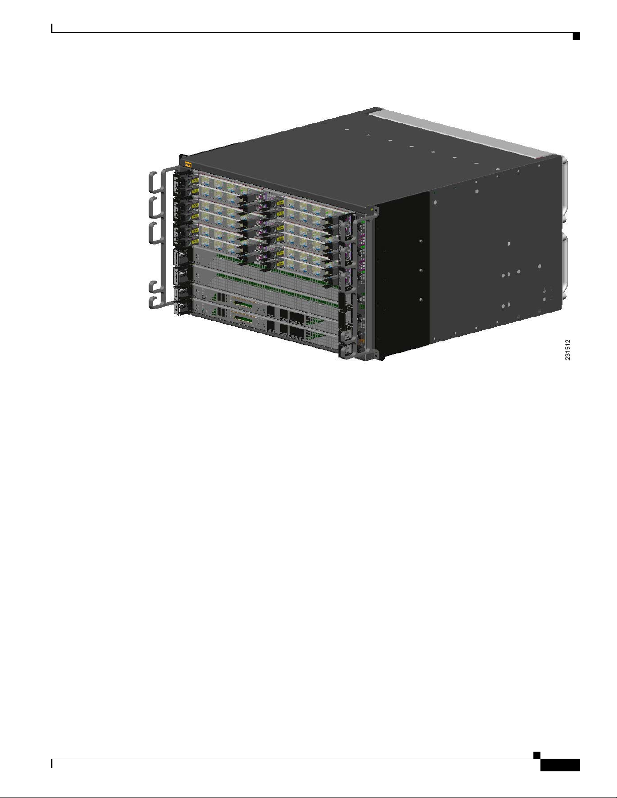
Figure 2-1 shows an example of a SIP installed on a Cisco ASR 1006 Router. The router has three
chassis slots for SIPs, and can accommodate a total of twelve SPAs.
Cisco ASR 1000 Series Aggregation Services Routers SIP and SPA Hardware Installation Guide
OL-14126-03
Page 19
Chapter 2 Overview: Cisco ASR 1000 Series Aggregation Services Routers SIPs
Figure 2-1 SIP and SPAs Installed in a Cisco ASR 1006 Router
Identifying Slots and Subslots for SIPs and SPAs
Some commands allow you to display information about the SIP itself, such as show platform, show
diag, and show diag subslot. These commands require you to specify the chassis slot location where the
SIP that you want information about is installed.
For example, to display status and slot-related information about the SIP installed in any of the chassis
slots, enter the following command:
Router# show platform
Chassis type: ASR1006
Slot Type State Insert time (ago)
--------- ------------------- --------------------- ----------------0 ASR1000-SIP10 ok 2d21h
0/0 SPA-2X1GE-V2 ok 2d21h
0/1 SPA-2X1GE-V2 ok 2d21h
0/2 SPA-2X1GE-V2 ok 2d21h
0/3 SPA-1XOC12-POS ok 2d21h
1 ASR1000-SIP10 ok 22:46:22
1/0 SPA-1X10GE-L-V2 ok 22:45:29
1/1 SPA-1XOC12-POS ok 22:45:26
1/2 SPA-1X10GE-L-V2 ok 22:45:22
1/3 SPA-1XOC12-POS ok 22:45:18
2 ASR1000-SIP10 ok 1d20h
2/0 SPA-5X1GE-V2 ok 1d20h
2/1 SPA-5X1GE-V2 ok 1d20h
2/2 SPA-5X1GE-V2 ok 1d20h
2/3 SPA-5X1GE-V2 ok 1d20h
R0 ASR1000-RP1 ok, active 3d20h
F0 ASR1000-ESP10 ok, active 3d20h
P0 ASR1006-PWR-AC ok 3d20h
P1 ASR1006-FAN ok 3d20h
OL-14126-03
Cisco ASR 1000 Series Aggregation Services Routers SIP and SPA Hardware Installation Guide
2-3
Page 20

Chapter 2 Overview: Cisco ASR 1000 Series Aggregation Services Routers SIPs
Identifying Slots and Subslots for SIPs and SPAs
Slot CPLD Version Firmware Version
--------- ------------------- --------------------------------------0 07091401 12.2(33r)XN2
1 07091401 12.2(33r)XN2
2 07091401 12.2(33r)XN2
R0 07082312 12.2(33r)XN2
Specifying the SIP Subslot Location for a SPA
SIP subslots begin their numbering with “0” and have a horizontal orientation, as shown in the “SIP and
SPA Product Overview” chapter of the Cisco ASR 1000 Series Aggregation Services Routers SIP and
SPA Software Configuration Guide.
The Cisco ASR 1000 series SIP supports four subslots for the installation of SPAs. As shown in
Figure 2-2, the subslot locations are oriented as follows:
• SIP subslot 0—Top-left subslot
• SIP subslot 1—Top-right subslot
• SIP subslot 2—Bottom-left subslot
• SIP subslot 3—Bottom-right subslot
Note In the Cisco ASR 1002 Router, SIP subslot 0 is not available for SPA insertion. It is the slot that is used
for the integrated Route Processor and Gigabit Ethernet ports.
Figure 2-2 shows the SPA numbering sequence on a Cisco ASR 1000 Series Routers SIP.
Figure 2-2 Cisco ASR 1000 Series SIP SPA Numbering
Front of SIP, horizontal chassis slots
SPA 0 SPA 1
SPA 2 SPA 3
231508
The SIP subslot numbering is indicated by a small numeric label beside the subslot on the faceplate.
Just as with the SIPs, some commands allow you to display information about the SPA itself, such as
show diag subslot. These commands require you to specify both the physical location of the SIP and
SPA in the format, slot/subslot, where:
• slot—Specifies the chassis slot number in the Cisco ASR 1000 Series Routers where the SIP is
installed.
• subslot—Specifies the slot of the SIP where the SPA is installed.
To display the operational status for a SPA installed in the SIP, enter the show platform command.
Router# show platform
Chassis type: ASR1006
2-4
Slot Type State Insert time (ago)
--------- ------------------- --------------------- ----------------0 ASR1000-SIP10 ok 2d21h
0/0 SPA-2X1GE-V2 ok 2d21h
0/1 SPA-2X1GE-V2 ok 2d21h
Cisco ASR 1000 Series Aggregation Services Routers SIP and SPA Hardware Installation Guide
OL-14126-03
Page 21
Chapter 2 Overview: Cisco ASR 1000 Series Aggregation Services Routers SIPs
0/2 SPA-2X1GE-V2 ok 2d21h
0/3 SPA-1XOC12-POS ok 2d21h
1 ASR1000-SIP10 ok 22:46:22
1/0 SPA-1X10GE-L-V2 ok 22:45:29
1/1 SPA-1XOC12-POS ok 22:45:26
1/2 SPA-1X10GE-L-V2 ok 22:45:22
1/3 SPA-1XOC12-POS ok 22:45:18
2 ASR1000-SIP10 ok 1d20h
2/0 SPA-5X1GE-V2 ok 1d20h
2/1 SPA-5X1GE-V2 ok 1d20h
2/2 SPA-5X1GE-V2 ok 1d20h
2/3 SPA-5X1GE-V2 ok 1d20h
R0 ASR1000-RP1 ok, active 3d20h
F0 ASR1000-ESP10 ok, active 3d20h
P0 ASR1006-PWR-AC ok 3d20h
P1 ASR1006-FAN ok 3d20h
Slot CPLD Version Firmware Version
--------- ------------------- --------------------------------------0 07091401 12.2(33r)XN2
1 07091401 12.2(33r)XN2
2 07091401 12.2(33r)XN2
R0 07082312 12.2(33r)XN2
Cisco ASR 1000 Series SPA Interface Processor Overview
Cisco ASR 1000 Series SPA Interface Processor Overview
The following sections describe the Cisco ASR1000-SIP10.
• Cisco ASR1000-SIP10 LEDs, page 2-5
• Cisco ASR1000-SIP10 Physical Specifications, page 2-6
Cisco ASR1000-SIP10 LEDs
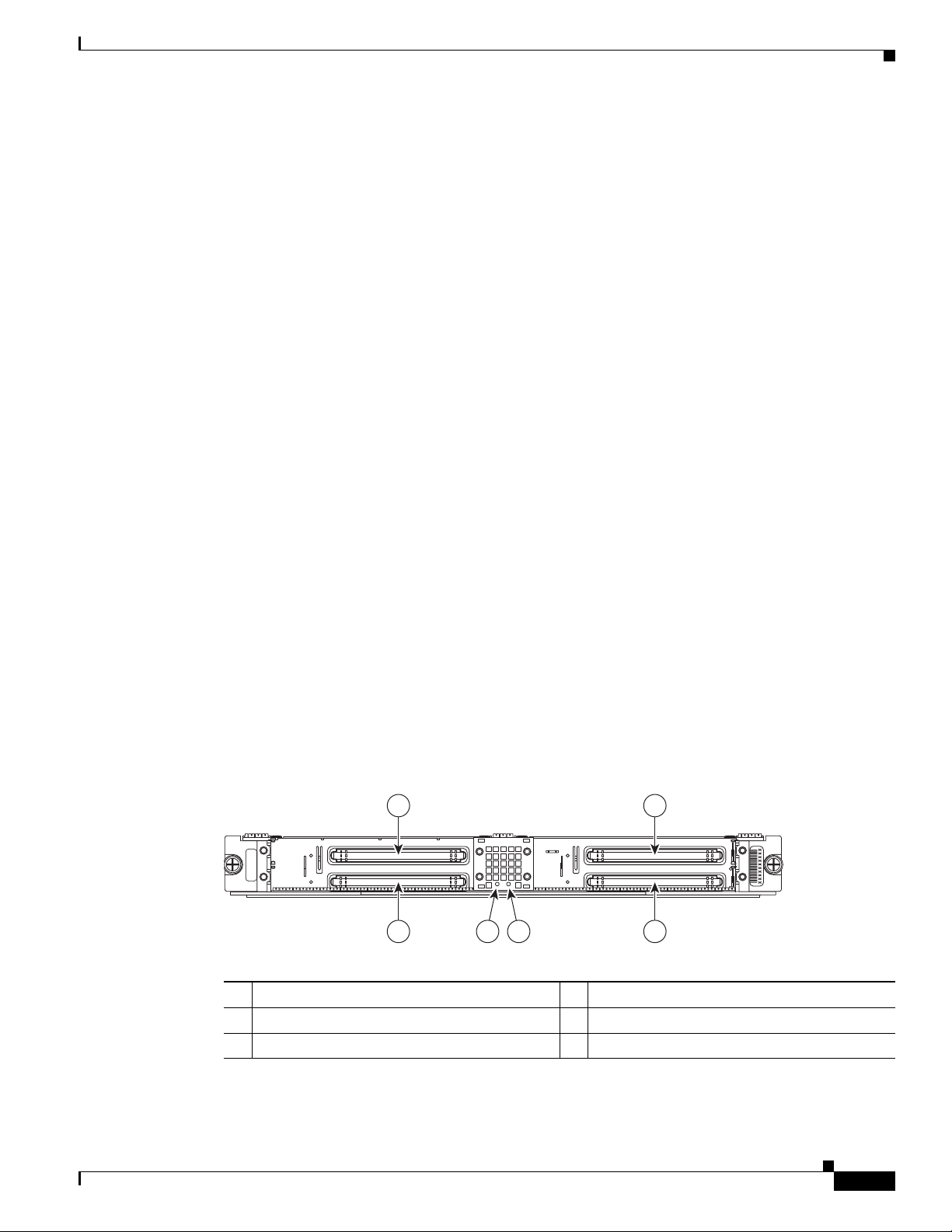
The Cisco ASR1000-SIP10 has two LEDs, as shown in Figure 2-3.
Figure 2-3 Cisco ASR1 000-SIP10 Faceplate
1 2
0
ASR1000-SIP10G
2
3
ASR1000-SIP10
PWR STATUS
1
3
546
231510
OL-14126-03
1 SPA, subslot 0 4 PWR LED
2 SPA, subslot 1 5 STATUS LED
3 SPA, subslot 2 6 SPA, subslot 3
The Cisco ASR1000-SIP10 LEDs are described in Table 2-3.
Cisco ASR 1000 Series Aggregation Services Routers SIP and SPA Hardware Installation Guide
2-5
Page 22

Chapter 2 Overview: Cisco ASR 1000 Series Aggregation Services Routers SIPs
Cisco ASR 1000 Series SPA Interface Processor Overview
Table 2-3 Cisco ASR1000-SIP10 LEDs
LED Label Color State Meaning
STATUS Red On The Cisco ASR1000-SIP10 has encountered an
Yellow On The Cisco ASR1000-SIP10 is loading.
Green On The Cisco ASR1000-SIP10 is online.
Off Off The Cisco ASR1000-SIP10 is powered off.
PWR Green On The Cisco ASR1000-SIP10 is powered on.
Off Off The Cisco ASR1000-SIP10 is powered off.
Cisco ASR1000-SIP10 Physical Specifications
The Cisco ASR1000-SIP10 physical specifications are shown in Table 2-4.
Table 2-4 Cisco ASR1000-SIP10 Physical Specifications
error.
Description Specifications
Physical dimension (HxWxD) 1.630 inches (41.4 mm) x 16.725 inches (424.8 mm) x
14.187
inches (360.3 mm)
Shipping weight 8.5 lb (3.9 kg)
Operating temperature Nominal—40.9 to 104°F (5 to 40°C)
Short Term—40.9 to 131°F (5 to 55°C)
Relative humidity Operating Humidity Nominal—5% to 85% noncondensing
Operating Humidity Short Term—5% to 90% noncondensing
Storage temperature –40 to 167°F (–20 to 70°C)
2-6
Cisco ASR 1000 Series Aggregation Services Routers SIP and SPA Hardware Installation Guide
OL-14126-03
Page 23

CHAPTER
3
Overview: Cisco ASR 1000 Series Aggregation Services Routers Shared Port Adapters
This chapter describes the shared port adapters (SPAs) that are supported on the Cisco ASR 1000 Series
Aggregation Services Routers and contains the following sections:
• SPA Summary, page 3-1
Serial SPAs
• 2-Port and 4-Port Clear Channel T3/E3 Serial SPA Overview, page 3-2
• 2-Port and 4-Port Channelized T3 Serial SPA Overview, page 3-4
• 4-Port Serial Interface SPA Overview, page 3-6
• 8-Port Channelized T1/E1 Serial SPA Overview, page 3-10
• 1-Port Channelized STM-1/OC-3 SPA Overview, page 3-12
Ethernet SPAs
• 4-Port and 8-Port Fast Ethernet SPA Overview, page 3-14
• 1-Port 10-Gigabit Ethernet SPA Overview, page 3-16
• 2-Port Gigabit Ethernet SPA Overview, page 3-19
• 5-Port Gigabit Ethernet SPA Overview, page 3-21
• 8-Port Gigabit Ethernet SPA Overview, page 3-23
• 10-Port Gigabit Ethernet SPA Overview, page 3-24
Packet Over SONET SPAs
• 2-Port and 4-Port OC-3c/STM-1 POS SPA Overview, page 3-31
• 2-Port and 4-Port OC-48c/STM-16 POS/RPR SPA Overview, page 3-35
• 1-Port OC-12c/STM-4 POS SPA Overview, page 3-38
SPA Summary
The SPAs listed in this section are supported on the Cisco ASR 1000 Series Aggregation Services
Routers.
OL-14126-03
Cisco ASR 1000 Series Aggregation Services Routers SIP and SPA Hardware Installation Guide
3-1
Page 24
Chapter 3 Overview: Cisco ASR 1000 Series Aggregation Services Routers Shared Port Adapters
2-Port and 4-Port Clear Channel T3/E3 Serial SPA Overview
Checking Hardware and Software Compatibility
To check the minimum software requirements of Cisco IOS software with the hardware installed on your
router, Cisco maintains the Software Advisor tool on Cisco.com. This tool does not verify whether SIPs
or SPAs within a system are compatible, but it does provide the minimum Cisco IOS requirements for
individual hardware modules or components.
Note Access to this tool is limited to users with Cisco.com login accounts.
To access Software Advisor, click Login at Cisco.com, type “Software Advisor” in the SEARCH box,
and click GO. Click the link for the Software Advisor tool.
Choose a product family or enter a specific product number to search for the minimum supported
software release needed for your hardware.
2-Port and 4-Port Clear Channel T3/E3 Serial SPA Overview
The following sections describe the 2-Port and 4-Port T3/E3 Clear Channel Serial SPA:
• 2-Port and 4-Port T3/E3 Clear Channel Serial SPA LEDs, page 3-2
• 2-Port and 4-Port T3/E3 Clear Channel Serial SPA Interface Specifications, page 3-3
• 2-Port and 4-Port T3/E3 Clear Channel Serial SPA Cables and Connectors, page 3-3
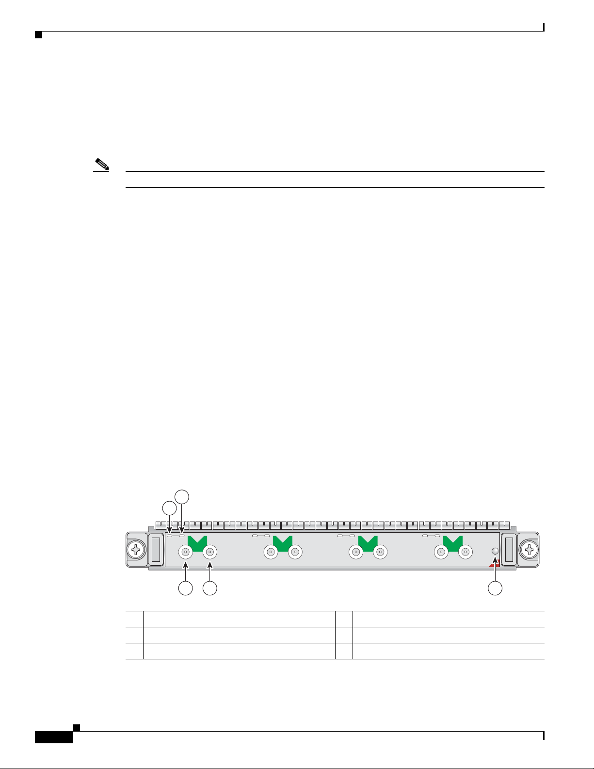
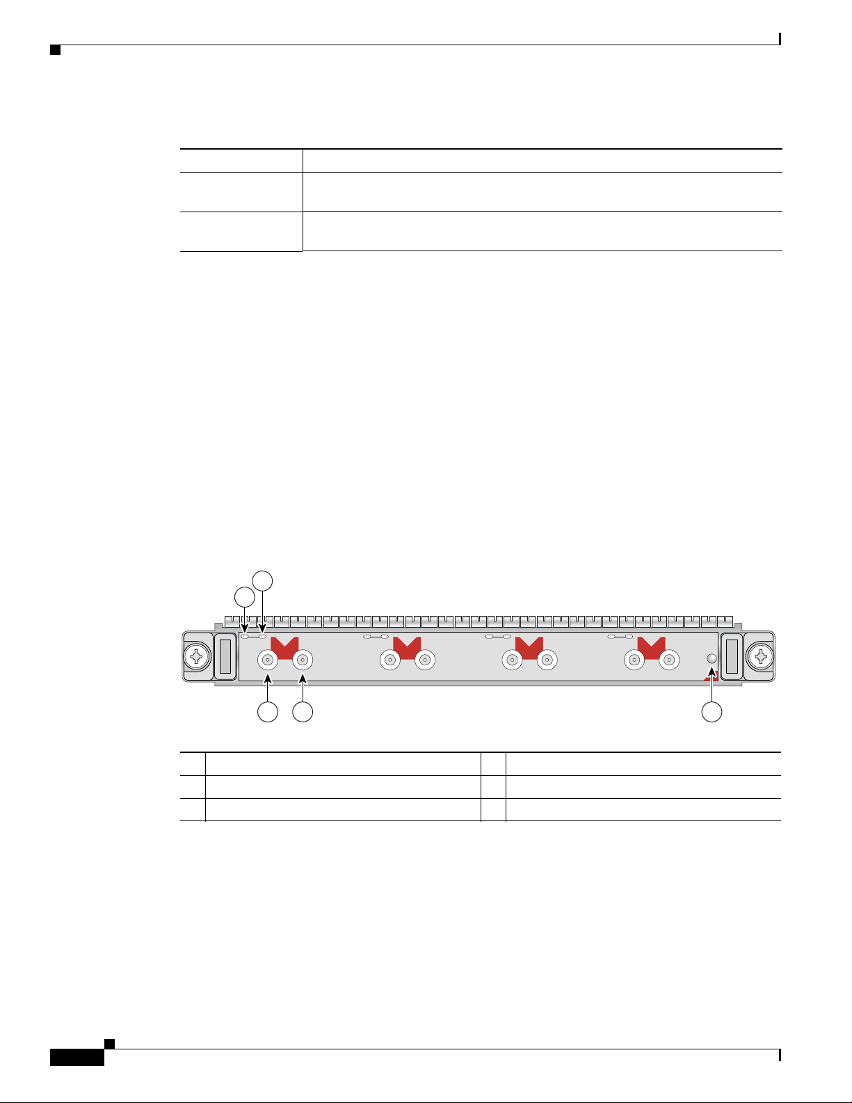
2-Port and 4-Port T3/E3 Clear Channel Serial SPA LEDs
The 2-Port and 4-Port T3/E3 Clear Channel Serial SPA has three types of LEDs: two LEDs for each port
on the SPA, and one STATUS LED, as shown in
Figure 3-1 4-Port T3/E3 Clear Channel Ser ial SPA Faceplate
2
1
0
A/L
C/A
TX
RX
C/A
1
A/L
TX
RX
3 4 5
Figure 3-1.
A/L
C/A
TX
2
RX
C/A
TX
RX
STATUS
SPA-4XT3/E3
203209
3
A/L
3-2
1 C/A (Carrier/Alarm) LED 4 RX (Receive) connector
2 A/L (Active Loopback) LED 5 STATUS LED
3 TX (Transmit) connector
Table 3-1 describes the 2-Port and 4-Port T3/E3 Clear Channel Serial SPA LEDs.
Cisco ASR 1000 Series Aggregation Services Routers SIP and SPA Hardware Installation Guide
OL-14126-03
Page 25

Chapter 3 Overview: Cisco ASR 1000 Series Aggregation Services Routers Shared Port Adapters
2-Port and 4-Port Clear Channel T3/E3 Serial SPA Overview
Table 3-1 2-Port and 4-Port T3/E3 Clear Channel Serial SPA LEDs
LED Label Color State Meaning
C/A Off Off Port is not enabled by software.
Green On Port is enabled by software, and there is a valid E3 or T3
signal without any alarms.
Amber On Port is enabled by software, and there is at least one alarm.
A/L Off Off Port is not enabled by software.
Green On Port is enabled by software, and loopback is off.
Amber On Port is enabled by software, and loopback is on.
STATUS Off Off SPA power is off.
Green On SPA is ready and operational.
Amber On SPA power is on and good, and the SPA is being configured.
2-Port and 4-Port T3/E3 Clear Channel Serial SPA Interface Specifications
The framer processes incoming and outgoing T3 (cbit, m13/m23, and unframe) and E3 (g751, g832, and
unframe) frames. The framer operates at T3/E3 line rates (44.736Mbps /34.368 Mbps) depending on the
mode in which it is configured.
Packet data is transported with a user-configurable encapsulation (such as Point-to-Point Protocol [PPP]
or High-Level Data Link Control [HDLC]), and is mapped to T3 and E3 frames. The encapsulations add
transport overhead to the packet of data frames before transporting, and are stripped when a packet is
transported to the far end.
The T3/E3 SPA interface is compliant with ANSI and Telco standards. The interface also provides
support for Management Information Base (MIB) RFC 2496 and T1.231.
2-Port and 4-Port T3/E3 Clear Channel Serial SPA Cables and Connectors
The interface connectors on the 2-Port and 4-Port T3/E3 Clear Channel Serial SPA are 75-ohm coaxial
Siemax types, with one connector and cable for transmit (TX) and one for receive (RX).
The following cables can be used with the 2-Port and 4-Port T3/E3 Clear Channel Serial SPA. The cables
have BNC connectors on one end and the Siemax connectors on the other.
• CAB-T3E3-RF-BNC-M (T3 or E3 Cable, 1.0/2.3 RF to BNC-Male, 10 feet)
• CAB-T3E3-RF-BNC-F (T3 or E3 Cable, 1.0/2.3 RF to BNC-Female, 10 feet)
• CAB-T3E3-RF-OPEN (T3 or E3 Cable, 1.0/2.3 RF to BNC-Open end, 10 feet)
OL-14126-03
Note The Cisco cable part numbers are 72-4124-01 (with male BNC end) and 72-4131-01 (with female BNC
end).
Figure 3-1 shows the connectors on the 4-Port T3/E3 Clear Channel Serial SPA, and Table 3-2 describes
the signal descriptions for these connectors.
Cisco ASR 1000 Series Aggregation Services Routers SIP and SPA Hardware Installation Guide
3-3
Page 26
Chapter 3 Overview: Cisco ASR 1000 Series Aggregation Services Routers Shared Port Adapters
2-Port and 4-Port Channelized T3 Serial SPA Overview
Table 3-2 2-Port and 4- Port T3/E3 Clear Channel Serial SPA Connectors
Connector Label Meaning
TX Transmitted signals appear on the center contact, and the outer shield is ground
for the 75-ohm RG-59 coaxial cable you attach to the TX Siemax connector.
RX Received signals appear on the center contact, and the outer shield is ground for
the 75-ohm RG-59 coaxial cable you attach to the RX Siemax connector.
2-Port and 4-Port Channelized T3 Serial SPA Overview
The following sections describe the 2-Port and 4-Port Channelized T3 Serial SPA:
• 2-Port and 4-Port Channelized T3 Serial SPA LEDs, page 3-4
• 2-Port and 4-Port Channelized T3 Serial SPA Interface Specifications, page 3-5
• 2-Port and 4-Port Channelized T3 Serial SPA Cables and Connectors, page 3-5
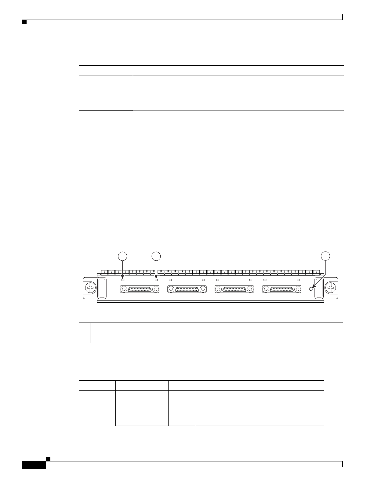
2-Port and 4-Port Channelized T3 Serial SPA LEDs
The 2-Port and 4-Port Channelized T3 Serial SPA has three types of LEDs: two LEDs for each port on
the SPA, and one STATUS LED, as shown in
Figure 3-2 4-Port Channelized T3 Serial SPA Faceplate
2
1
0
A/L
C/A
TX
RX
C/A
1
A/L
TX
3 4 5
1 C/A (Carrier/Alarm) LED 4 RX (Receive) connector
2 A/L (Active Loopback) LED 5 STATUS LED
3 TX (Transmit) connector
RX
Figure 3-2.
C/A
TX
2
A/L
RX
C/A
A/L
TX
3
RX
SPA-4XCT3/DS0
STATUS
116854
3-4
Cisco ASR 1000 Series Aggregation Services Routers SIP and SPA Hardware Installation Guide
OL-14126-03
Page 27

Chapter 3 Overview: Cisco ASR 1000 Series Aggregation Services Routers Shared Port Adapters
Table 3-3 describes the 2-Port and 4-Port Channelized T3 Serial SPA LEDs.
Table 3-3 2-Port and 4-Port Channelized T3 Serial SPA LEDs
LED Label Color State Meaning
C/A Off Off Port is not enabled by software.
Green On Port is enabled by software, and there is a valid T3 signal
without any alarms.
Amber On Port is enabled by software, and there is at least one alarm.
A/L Off Off Port is not enabled by software.
Green On Port is enabled by software, loopback is off.
Amber On Port is enabled by software, loopback is on.
STATUS Off Off SPA power is off.
Green On SPA is ready and operational.
Amber On SPA power is on and good, and SPA is being configured.
2-Port and 4-Port Channelized T3 Serial SPA Overview
2-Port and 4-Port Channelized T3 Serial SPA Interface Specifications
The framer processes incoming and outgoing T3 frames (cbit, m13/m23, and unframe). The framer
operates at T3 line rates (44.2 Mbps).
Packet data is transported with a user-configurable encapsulation (such as Point-to-Point Protocol [PPP]
or High-Level Data Link Control [HDLC]), and is mapped to T3 frames. The encapsulations add
transport overhead to the packet of data frames before transporting, and are stripped when a packet is
transported to the far end.
The T3 SPA interface is compliant with ANSI and Telco standards. The interface also provides support
for Management Information Base (MIB) RFC 2495, RFC 2496, and T1.231.
2-Port and 4-Port Channelized T3 Serial SPA Cables and Connectors
The interface connectors on the 2-Port and 4-Port Channelized T3 Serial SPA are 75-ohm coaxial
Siemax types, with one connector and cable for transmit (TX) and one for receive (RX).
The following cables can be used with the 2-Port and 4-Port Channelized T3 Serial SPA. The cables have
BNC connectors on one end and the Siemax connectors on the other.
• CAB-T3E3-RF-BNC-M (T3 or E3 Cable, 1.0/2.3 RF to BNC-Male, 10 feet)
• CAB-T3E3-RF-BNC-F (T3 or E3 Cable, 1.0/2.3 RF to BNC-Female, 10 feet)
• CAB-T3E3-RF-OPEN (T3 or E3 Cable, 1.0/2.3 RF to BNC-Open end, 10 feet)
OL-14126-03
Note The Cisco cable part numbers are 72-4124-01 (with Male BNC end) and 72-4131-01 (with Female BNC
end).
Figure 3-2 shows the connectors on the 4-Port Channelized T3 Serial SPA, and Table 3-4 provides the
signal descriptions for these connectors.
Cisco ASR 1000 Series Aggregation Services Routers SIP and SPA Hardware Installation Guide
3-5
Page 28
Chapter 3 Overview: Cisco ASR 1000 Series Aggregation Services Routers Shared Port Adapters
4-Port Serial Interface SPA Overview
Table 3-4 2-Port and 4-Port Channelized T3 Serial SPA Connectors
Connector Label Meaning
TX Transmitted signals appear on the center contact, and the outer shield is ground
for the 75-ohm RG-59 coaxial cable you attach to the TX Siemax connector.
RX Received signals appear on the center contact, and the outer shield is ground for
the 75-ohm RG-59 coaxial cable you attach to the RX Siemax connector.
4-Port Serial Interface SPA Overview
The following sections describe the 4-Port Serial Interface SPA:
• 4-Port Serial Interface SPA LEDs, page 3-6
• 4-Port Serial Interface SPA Interface Specifications, page 3-7
• 4-Port Serial Interface SPA Cables, Connectors, and Pinouts, page 3-8
4-Port Serial Interface SPA LEDs
The 4-Port Serial Interface SPA has three types of LEDs: two LEDs for each port on the SPA, and one
STATUS LED, as shown in
Figure 3-3 4-Port Serial Interface SPA Faceplate
1 2
0
ACTIVE
1 ACTIVE LED 3 STATUS LED
2 CD/LB (Carrier Detect / Loopback) LED
Table 3-5 describes the 4-Port Serial Interface SPA LEDs.
Table 3-5 4-Port Serial Interface LEDs
CD/
Figure 3-3.
LB
ACTIVE
3
E
V
CD/ LB
ACT
I
2
1
CD/
E
LB
IV
CT
A
3
CD/
SPA-4XT-SERIAL
B
L
S
U
AT
T
S
250158
3-6
LED Label Color State Function
ACTIVE Off Off The SPA port is not enabled by the
field-programmable gate array (FPGA).
The SPA port does not have any frame activity
on RX/TX Layer 1.
Cisco ASR 1000 Series Aggregation Services Routers SIP and SPA Hardware Installation Guide
OL-14126-03
Page 29

Chapter 3 Overview: Cisco ASR 1000 Series Aggregation Services Routers Shared Port Adapters
Table 3-5 4-Port Serial Interface LEDs (continued)
Green Blinking The SPA port is enabled by the FPGA, and it has
Rx/Tx Layer 1 frame activity.
Amber On This state is unused.
CD/LB Off Off The SPA port is not enabled.
Green On The SPA port is enabled, and DTR, DSR, RTS,
CTS, or DCD is active.
Amber On The SPA port is enabled, and local loopback or
internal loopback is active.
STATUS Off Off The SPA is powered off (power is not within
required specification) or Status On conditions
not met.
Green On The SPA is powered on and operational (power
is within required specification, and
initialization is complete).
The following conditions must be met before the
STATUS LED goes on:
• The SPA is correctly connected and
receiving power.
4-Port Serial Interface SPA Overview
• The SPA equipped card or router contains a
valid microcode version that has been
downloaded successfully.
• The bus recognizes the SPA.
• The SPA is up to date on the FPD versions
required by the router software.
Amber On The SPA is powered on but initializing (power is
within required specification, but the hardware
and software initialization sequence is not
complete).
4-Port Serial Interface SPA Interface Specifications
The 4-Port Serial Interface SPA supports six interfaces in DCE and DTE mode:
• V.35
• EIA/TIA-232
• EIA/TIA-449
• EIA/TIA-530
• EIA/TIA-530A
• X.21
The 4-Port Serial Interface SPA provides up to four synchronous serial interfaces. Each port allows a
maximum bandwidth of 8064 Kbps except for the X.21 and EIA/TIA-232 interfaces.
OL-14126-03
Cisco ASR 1000 Series Aggregation Services Routers SIP and SPA Hardware Installation Guide
3-7
Page 30

Chapter 3 Overview: Cisco ASR 1000 Series Aggregation Services Routers Shared Port Adapters
4-Port Serial Interface SPA Overview
Use EIA/TIA-232 for speeds of 128 kilobits per second (kbps) and below. Use X.21 for speeds less than
2 Mbps. Use EIA/TIA-449, V.35, EIA/TIA-530, or EIA/TIA-530A for higher speeds.
4-Port Serial Interface SPA Cables, Connectors, and Pinouts
The 4-Port Serial Interface SPA uses Smart Serial cable interfaces that support two independent serial
interface ports. The serial end of the Smart Serial cable is a 26-pin connector.
Table 3-6 lists the 4-Port Serial Interface SPA cable interfaces.
Table 3-6 4-Port Serial Interface SPA Cables
Product Number Cable Type Length Connector Type
CAB-SS-V35MT V.35 DTE 10 feet (3 meters) Male
CAB-SS-V35FC V.35 DCE 10 feet (3 meters) Female
CAB-SS-232MT EIA/TIA-232 DTE 10 feet (3 meters) Male
CAB-SS-232FC EIA/TIA-232 DCE 10 feet (3 meters) Female
CAB-SS-449MT EIA/TIA-449 DTE 10 feet (3 meters) Male
CAB-SS-449FC EIA/TIA-449 DCE 10 feet (3 meters) Female
CAB-SS-X21MT X.21 DTE 10 feet (3 meters) Male
CAB-SS-X21FC X.21 DCE 10 feet (3 meters) Female
CAB-SS-530MT EIA/TIA-530 DTE 10 feet (3 meters) Male
CAB-SS-530AMT EIA/TIA-530A DTE 10 feet (3 meters) Male
Figure 3-4 shows the Smart Serial cable connectors.
3-8
Cisco ASR 1000 Series Aggregation Services Routers SIP and SPA Hardware Installation Guide
OL-14126-03
Page 31

Chapter 3 Overview: Cisco ASR 1000 Series Aggregation Services Routers Shared Port Adapters
Figure 3-4 Smart Serial Cable Connectors
Router connections
4-Port Serial Interface SPA Overview
205059
EIA/TIA-232 EIA-530
EIA/TIA-449 V.35 X.21
Network connections at the modem or CSU/DSU
Table 3-7 lists the connector pinouts for the Smart Serial connectors that interface at the 4-Port Serial
Interface SPA ports.
Table 3-7 Smart Serial Connector Pinouts
Pin Signal Pin Signal
1 O_TXD/RXD+ 14 O_TXD/RXD-
2 O_TXCE/RXC+ 15 O_TXCE/RXC-
3 B_TXC/TXC+ 16 B_TXC/TXC-
4 I_RXC/TXCE+ 17 I_RXC/TXCE-
5 I_RXD/TXD+ 18 I_RXD/TXD-
6 B_DCD/DCD+ 19 B_DCD/DCD-
7 O_DTR/DSR+ 20 O_DTR/DSR-
8 O_RTS/CTS+ 21 MODE2
9 O_RTS/CTS- 22 MODE1
10 I_CTS/RTS- 23 MODE0
11 I_CTS/RTS+ 24 MODEDCE
OL-14126-03
Cisco ASR 1000 Series Aggregation Services Routers SIP and SPA Hardware Installation Guide
3-9
Page 32

Chapter 3 Overview: Cisco ASR 1000 Series Aggregation Services Routers Shared Port Adapters
8-Port Channelized T1/E1 Serial SPA Overview
Table 3-7 Smart Serial Connector Pinouts
Pin S ignal Pin Signal
12 I_DSR/DTR+ 25 I_DSR/DTR-
13 B_LL/LL+ 26 GND
8-Port Channelized T1/E1 Serial SPA Overview
The following sections describe the 8-Port Channelized T1/E1 Serial SPA:
• 8-Port Channelized T1/E1 Serial SPA LEDs, page 3-10
• 8-Port Channelized T1/E1 Serial SPA Interface Specifications, page 3-11
• 8-Port Channelized T1/E1 Serial SPA Cables, Connectors, and Pinouts, page 3-11
8-Port Channelized T1/E1 Serial SPA LEDs
The 8-Port Channelized T1/E1 Serial SPA has three types of LEDs: two LEDs for each port on the SPA,
and one STATUS LED, as shown in
Figure 3-5 8-Port Channelized T1/E1 Serial SPA Faceplate
Figure 3-5.
2
1
C/A A/L
SPA-8XCHT1/E1
0
C/A
1
A/L A/L A/LC/A
2
C/A
3
4
C/A A/L
C/A
A/L A/L A/LC/A
6
5
C/A
7
STATUS
3
1 C/A (Carrier/Alarm) LED 3 STATUS LED
2 A/L (Active/Loopback) LED
Table 3-8 describes the 8-Port Channelized T1/E1 Serial SPA LEDs.
Table 3-8 8-Port Channelized T1/E1 Serial SPA LEDs
LED Label Color State Meaning
C/A Off Off Port is not enabled by software.
Green On Port is enabled by software, and there is a valid T1 or E1
signal without any alarms.
Amber On Port is enabled by software, and there is at least one alarm.
116852
3-10
Cisco ASR 1000 Series Aggregation Services Routers SIP and SPA Hardware Installation Guide
OL-14126-03
Page 33

Chapter 3 Overview: Cisco ASR 1000 Series Aggregation Services Routers Shared Port Adapters
8-Port Channelized T1/E1 Serial SPA Overview
Table 3-8 8-Port Channelized T1/E1 Serial SPA LEDs
LED Label Color State Meaning
A/L Off Off Port is not enabled by software.
Green On Port is enabled by software, loopback is off.
Amber On Port is enabled by software, loopback is on.
STATUS Off Off SPA power is off.
Green On SPA is ready and operational.
Amber On SPA power is on and good, and SPA is being configured.
8-Port Channelized T1/E1 Serial SPA Interface Specifications
The E1 interface on the 8-Port Channelized T1/E1 Serial SPA uses RJ-48c receptacles for E1 (120-Ohm)
cables with RJ-45 connectors. You can use all ports simultaneously. Each E1 connection supports
interfaces that meet G.703 standards. The RJ-45 connection does not require an external transceiver. The
E1 ports are E1 interfaces that use 120-ohm shielded twisted pair (STP) cables.
Caution Shielded T1/E1 cables must be used to comply with FCC/EN55022/CISPR22 Class A emissions
requirements.
8-Port Channelized T1/E1 Serial SPA Cables, Connectors, and Pinouts
Figure 3-6 shows an RJ-45 connector.
Figure 3-6 RJ-45 Connector
RJ-45
RJ-48c
Pin 1
Pin 8
Table 3-9 describes the signals and connector pinouts for RJ-45 cable connectors.
Table 3-9 RJ-45 Connector Pinouts
Pin Signal Description
1 RX– Receive ring –
2 RX+ Receive tip +
3 NC No connection
4 TX– Transmit ring –
5 TX+ Transmit tip +
6 NC No connection
32770
OL-14126-03
Cisco ASR 1000 Series Aggregation Services Routers SIP and SPA Hardware Installation Guide
3-11
Page 34

Chapter 3 Overview: Cisco ASR 1000 Series Aggregation Services Routers Shared Port Adapters
1-Port Channelized STM-1/OC-3 SPA Overview
Table 3-9 RJ-45 Connector Pinouts (continued)
Pin S ignal Description
7 NC No connection
8 NC No connection
1-Port Channelized STM-1/OC-3 SPA Overview
The following sections describe the 1-Port Channelized STM-1/OC-3 SPA:
• 1-Port Channelized STM-1/OC-3 SPA LEDs, page 3-12
• 1-Port Channelized STM-1/OC-3 SPA Interface Specifications, page 3-13
• 1-Port Channelized STM-1/OC-3 SPA Cables and Connectors, page 3-13
1-Port Channelized STM-1/OC-3 SPA LEDs
The 1-Port Channelized STM-1/OC-3 SPAhas three types of LEDs: a C\A LED, an A/L LED, and a
STATUS LED, as shown in
Figure 3-7 1-Port Channelized STM-1/OC-3 SPA Faceplate
Figure 3-7.
1
C/A
A/L
0
SPA-1XCHSTM1/OC3
STATUS
2
3
1 C/A (Carrier/Alarm) LED 3 STATUS LED
2 A/L (Active Loopback) LED
Table 3-10 describes the 1-Port Channelized STM-1/OC-3 SPALEDs.
Table 3-10 1-Port Channelized STM-1/OC-3 SPA LEDs
LED Label Color State Meaning
C/A Off Off Port is not enabled by software.
Green On Port is enabled by software, and there is a valid T3 signal
without any alarms.
Amber On Port is enabled by software, and there is at least one alarm.
A/L Off Off Port is not enabled by software.
Green On Port is enabled by software, and loopback is off.
138847
3-12
Cisco ASR 1000 Series Aggregation Services Routers SIP and SPA Hardware Installation Guide
OL-14126-03
Page 35

Chapter 3 Overview: Cisco ASR 1000 Series Aggregation Services Routers Shared Port Adapters
1-Port Channelized STM-1/OC-3 SPA Overview
Table 3-10 1-Port Channelized STM-1/OC-3 SPA LEDs (continued)
LED Label Color State Meaning
Amber On Port is enabled by software, and loopback is on.
STATUS Off Off SPA power is off.
Green On SPA is ready and operational.
Amber On SPA power is on and good, and SPA is being configured.
1-Port Channelized STM-1/OC-3 SPA Interface Specifications
The framer processes incoming and outgoing SONET or SDH frames. The framer operates at
OC-3c/STM-1 line rates (155.52 Mbps).
Packet data is transported with a user-configured encapsulation (such as Point-to-Point Protocol [PPP]),
and is mapped into the STS-3c/STM-1 frame.
The 1-Port Channelized STM-1/OC-3 SPAinterface is compliant with RFC 1619, PPP over
SONET/SDH, and RFC 1662, PPP in HDLC-like Framing. The 1-Port Channelized STM-1/OC-3 SPA
also provides support for SNMP v1 agent (RFC 1155–1157), and Management Information Base (MIB)
II (RFC 1213).
1-Port Channelized STM-1/OC-3 SPA Cables and Connectors
The 1-Port Channelized STM-1/OC-3 SPAuses a small form-factor pluggable (SFP) optical transceiver
module installed in the port for SONET and SDH single-mode and multimode optical fiber connection
(See
Figure 3-8.)
Figure 3-8 SFP Optics Module
127158
The SFP optical transceiver modules used with the 1-Port Channelized STM-1/OC-3 SPA provide the
following optical fiber options:
OL-14126-03
• Multimode—155-Mbps, OC-3c/STM-1 optical fiber (SONET STS-3c or SDH STM-1)
Use a multimode optical fiber that has a core or cladding diameter of 62.5/125 microns.
• Single-mode—155-Mbps, OC-3c/STM-1 optical fiber (SONET STS-3c or SDH STM-1)
Cisco ASR 1000 Series Aggregation Services Routers SIP and SPA Hardware Installation Guide
3-13
Page 36

4-Port and 8-Port Fast Ethernet SPA Overview
Use a single-mode optical fiber that has a modal-field diameter of 8.7 ± 0.5 microns. (Nominal
diameter is approximately 10/125 microns.)
For single-mode and multimode optical fiber connections, you can use either a duplex LC-type cable
(see
Figure 3-9) or two simplex LC-type cables, one for transmit (TX) and one for receive (RX).
Use single-mode (for intermediate- or long-reach configurations) or multimode optical fiber cable to
connect your router to a network or to connect two 1-Port Channelized STM-1/OC-3 SPA-equipped
routers back-to-back.
Long-range SFP optical transceiver modules (for long-reach configurations) cannot be connected
back-to-back without using an attenuator between the two of them.
Figure 3-9 LC Type Cables
Chapter 3 Overview: Cisco ASR 1000 Series Aggregation Services Routers Shared Port Adapters
/ /
/ / / /
TXRX
4-Port and 8-Port Fast Ethernet SPA Overview
The following sections describe the 4-Port and 8-Port Fast Ethernet SPA:
• 4-Port and 8-Port Fast Ethernet SPA LEDs, page 3-14
• 4-Port and 8-Port Fast Ethernet SPA Cables, Connectors, and Pinouts, page 3-15
4-Port and 8-Port Fast Ethernet SPA LEDs
The 4-Port and 8-Port Fast Ethernet SPA has two types of LEDs: an A/L LED for each port on the SPA,
and one STATUS LED, as shown in
Figure 3-10 8-Port Fast Ethernet SPA Faceplate
1 2
0
SPA-8X1FE-TX-V2
A/L
1
A/L
Figure 3-10.
2
A/L
3
A/L
4
A/L
5
A/L
84929
6
A/L
7
A/L
STATUS
138712
3-14
1 A/L (Active/Link) LED 2 STATUS LED
Table 3-11 describes the 4-Port and 8-Port Fast Ethernet SPA LEDs.
Cisco ASR 1000 Series Aggregation Services Routers SIP and SPA Hardware Installation Guide
OL-14126-03
Page 37

Chapter 3 Overview: Cisco ASR 1000 Series Aggregation Services Routers Shared Port Adapters
4-Port and 8-Port Fast Ethernet SPA Overview
Table 3-11 4-Port and 8-Port Fast Ethernet SPA LEDs
LED Label Color State Meaning
Port Number
A/L (0, 1, 2, 3,
4, 5, 6 or 7)
Off Off Port is not enabled.
Green On Port is enabled and the link is up.
1
Amber On Port is enabled and the link is down.
STATUS Off Off SPA power is off.
Green On SPA is ready and operational.
Amber On SPA power is on and good, and the SPA is being
configured.
1. In this case, port number refers to the numbered LEDs on the 8-Port Fast Ethernet SPA (0, 1, 2, 3, 4, 5, 6, or 7). Each LED
number on the 8-Port Fast Ethernet SPA references a port on the SPA.
4-Port and 8-Port Fast Ethernet SPA Cables, Connectors, and Pinouts
The interface connectors on the 4-Port and 8-Port Fast Ethernet SPA are four or eight individual RJ-45
receptacles. You can use all interface connectors simultaneously. Each connection supports IEEE
802.3
and Ethernet 10/100BASE-T interfaces compliant with appropriate standards. Cisco does not supply
Category 5 unshielded twisted pair
(UTP) RJ-45 cables; these cables are available commercially.
Figure 3-11 shows the RJ-45 connector. Table 3-12 lists the pinouts and signals for the RJ-45 connector.
Figure 3-11 RJ-45 Connections, Plug, and Receptacle
8 7 6 5 4 3 2 1
RJ-45 connector
Table 3-12 RJ-45 Connector Pinout
205060
Pin Description
1 Transmit data + (TxD+)
2 TxD–
3 Receive data + (RxD+)
6 RxD–
OL-14126-03
Note Referring to the RJ-45 pinout in Table 3-12, proper common-mode line terminations should be used for
the unused Category 5 UTP cable pairs 4/5 and 7/8. Common-mode termination reduces the
contributions to electromagnetic interference (EMI) and susceptibility to common-mode sources. Wire
pairs 4/5 and 7/8 are actively terminated in the RJ-45 port circuitry in the 4-Port and 8-Port Fast Ethernet
SPA.
Cisco ASR 1000 Series Aggregation Services Routers SIP and SPA Hardware Installation Guide
3-15
Page 38

1-Port 10-Gigabit Ethernet SPA Overview
The 4-Port and 8-Port Fast Ethernet SPA supports automatic MDI/MDIX crossover at all speeds of
operation allowing the SPA to work with straight-through and crossover Ethernet cables. Depending on
your RJ-45 interface cabling requirements, use the pinouts in
Figure 3-12 Straight-Through Cable Pinout, RJ-45 Connection to a Hub or Repeater
Hub or LAN switch Ethernet port
3 TxD+
6 TxD–
1 RxD+
2 RxD–
Figure 3-13 Crossover Cable Pinout, RJ-45 Connections Between Routers
Chapter 3 Overview: Cisco ASR 1000 Series Aggregation Services Routers Shared Port Adapters
Figure 3-12 and Figure 3-13.
3 RxD+
6 RxD–
1 TxD+
2 TxD–
H7101
Router
3 TxD+
6 TxD–
1 RxD+
2 RxD–
Router
3 TxD+
6 TxD–
1 RxD+
2 RxD–
101929
1-Port 10-Gigabit Ethernet SPA Overview
The following sections describe the 1-Port 10-Gigabit Ethernet SPA:
• 1-Port 10-Gigabit Ethernet SPA LEDs, page 3-16
• 1-Port 10-Gigabit Ethernet SPA XFP Optical Transceiver Modules, Connectors, and Cables,
page 3-17
1-Port 10-Gigabit Ethernet SPA LEDs
The 1-Port 10-Gigabit Ethernet SPA has two LEDs, an ACTIVE/LINK LED for the port and a STATUS
LED, as shown in
Figure 3-14.
3-16
Figure 3-14 1-Port 10-Gigabit Ethernet SPA Faceplate
ACTIVE/LINK
1 2
1 ACTIVE/LINK LED 2 STATUS LED
Cisco ASR 1000 Series Aggregation Services Routers SIP and SPA Hardware Installation Guide
SPA-1X10GE-L-V2
STATUS
122151
OL-14126-03
Page 39

Chapter 3 Overview: Cisco ASR 1000 Series Aggregation Services Routers Shared Port Adapters
1-Port 10-Gigabit Ethernet SPA Overview
Table 3-13 describes the 1-Port 10-Gigabit Ethernet SPA LEDs.
Table 3-13 1-Port 10-Gigabit Ethernet SPA LEDs
LED Label Color State Meaning
ACTIVE/LINK Off Off Port is not enabled by software.
Green On Port is enabled by software and the link is up.
Amber On Port is enabled by software and the link is down.
STATUS Off Off SPA power is off.
Green On SPA is ready and operational.
Amber On SPA power is on and good, and the SPA is being
configured.
1-Port 10-Gigabit Ethernet SPA XFP Optical Transceiver Modules, Connectors, and Cables
The 1-Port 10-Gigabit Ethernet SPA supports the following types of optical transceiver modules:
• Single-mode short-reach (SR) XFP module—XFP-10GLR-OC192SR
• Single-mode intermediate-reach (IR) XFP module—XFP-10GER-OC192IR
• Single-mode very-long-reach (ZR) XFP module—XFP-10GZR-OC192LR
Cisco qualifies the optics that are approved for use with its SPAs. The above-listed small form-factor
pluggable
Use a single-mode optical fiber that has a modal-field diameter of 8.7 ±0.5 microns (nominal diameter
is approximately 10/125 microns) to connect your router to a network.
Figure 3-15 shows the cable type for use with the XFP optical transceiver module on the 1-Port
10-Gigabit Ethernet SPA.
Figure 3-15 LC Type Cables
modules (XFPs) are the only optical transceiver modules qualified for use.
/ /
/ / / /
TXRX
84929
OL-14126-03
Note The 40-pin connector on the 1-Port 10-Gigabit Ethernet SPA is used for resilient packet ring (RPR)
connections
Cisco ASR 1000 Series Aggregation Services Routers SIP and SPA Hardware Installation Guide
3-17
Page 40

1-Port 10-Gigabit Ethernet SPA Overview
XFP Connections
The XFP-10GLR-OC192SR, XFP-10GER-OC192IR, and XFP-10GZR-OC192LR modules include an
optical transmitter and receiver pair integrated with Clock and Data Recovery
The XFP modules provide high-speed serial links at the rate of 10.3125 Gbps (10 Gigabit Ethernet) on
single-mode fiber (SMF). The transmit side recovers and retimes the 10-Gbps serial data and passes it
to a laser driver. The laser driver biases and modulates a 1310-nm or 1550-nm laser, enabling data
transmission over SMF through an LC connector. The receive side recovers and retimes the 10-Gbps
optical data stream from a photo detector transimpedance amplifier and passes it to an output driver.
See the label on the XFP module for technology type and model. Figure 3-16 shows an XFP module and
Table 3-14 shows the XFP module specifications.
Figure 3-16 XFP Module
Chapter 3 Overview: Cisco ASR 1000 Series Aggregation Services Routers Shared Port Adapters
(CDR) integrated circuits.
129499
Table 3-14 XFP Module Specifications for the 1-Port 10-Gigabit Ethernet SPA
Specification Description
Dimensions (height x width x length) 12.5 mm x 18.35 mm x 71.1 mm
Wavelength (TX) 10GLR SR-1: 1260 nm to 1355 nm
10GER IR-2: 1530 nm to 1565 nm
10GZR LR-2: 1530 nm to 1565 nm
Cabling distance (maximum) 10GLR SR-1: 6.2 miles (10 km)
10GER IR-2: 24.8 miles (40 km)
10GZR LR-2: 50 miles (80 km)
Operating case temperature range 10GLR SR-1: 23 to 158oF (–5 to 70oC)
10GER IR-2: 23 to 158oF (–5 to 70oC)
10GZR LR-2: 23 to 158oF (–5 to 70oC)
Storage temperature range 10GLR SR-1: –40 to 185oF (–40 to 85oC)
10GER IR-2: –40 to 185oF (–40 to 85oC)
10GZR LR-2: –40 to 185oF (–40 to 85oC)
TX power 10GLR SR-1: –8.2 to 0.5 dBm
10GER IR-2: –4.7 to 4 dBm
10GZR LR-2: 0 to 4 dBm
Receiver sensitivity (maximum) 10GLR SR-1: –12.6 dBm
10GER IR-2: –14.1 dBm
10GZR LR-2: –24 dBm
3-18
Cisco ASR 1000 Series Aggregation Services Routers SIP and SPA Hardware Installation Guide
OL-14126-03
Page 41

Chapter 3 Overview: Cisco ASR 1000 Series Aggregation Services Routers Shared Port Adapters
Table 3-14 XFP Module Specifications for the 1-Port 10-Gigabit Ethernet SPA (continued)
Specification Description
RX overload 10GLR SR-1: 0.5 dBm
10GER IR-2: –1.0 dBm
10GZR LR-2: –7.0 dBm
Maximum receiver power damage 10GLR SR-1: 5 dBm
10GER IR-2: 5 dBm
10GZR LR-2: 5 dBm
XFP Port Cabling Specifications
Table 3-15 shows the port cabling specifications for an XFP module.
Table 3-15 XFP Port Cabling Specifications
XFP Module Wavelength Fiber Type
XFP-10GLR-OC192SR 1310 nm SMF
XFP-10GER-OC192IR 1550 nm SMF
XFP-10GZR-OC192LR 1550 nm SMF
2-Port Gigabit Ethernet SPA Overview
2-Port Gigabit Ethernet SPA Overview
The following sections describe the 2-Port Gigabit Ethernet SPA:
• 2-Port Gigabit Ethernet SPA LEDs, page 3-19
• 2-Port Gigabit Ethernet SPA Cables, Connectors, and Pinouts, page 3-20
2-Port Gigabit Ethernet SPA LEDs
The 2-Port Gigabit Ethernet SPA has two types of LEDs: an A/L LED for each port on the SPA, and one
STATUS LED, as shown in
Figure 3-17 2-Port Gigabit Ether net SPA Faceplate
A/L
0
Figure 3-17.
1
A/L
1
A/L
0
A/L
1
SPA-2X1GE-V2
STATUS
2
211969
OL-14126-03
1 A/L (Active/Link) LED 2 STATUS LED
Table 3-16 describes the 2-Port Gigabit Ethernet SPA LEDs.
Cisco ASR 1000 Series Aggregation Services Routers SIP and SPA Hardware Installation Guide
3-19
Page 42

Chapter 3 Overview: Cisco ASR 1000 Series Aggregation Services Routers Shared Port Adapters
2-Port Gigabit Ethernet SPA Overview
Table 3-16 2-Por t Gi gabit Ethernet SPA LEDs
LED Label Color State Meaning
A/L Off Off Port is not enabled.
Green On Port is enabled and the link is up.
Amber On Port is enabled and the link is down.
STATUS Off Off SPA power is off.
Green On SPA is ready and operational.
Amber On SPA power is on and good, and SPA is being configured.
2-Port Gigabit Ethernet SPA Cables, Connectors, and Pinouts
The 2-Port Gigabit Ethernet SPA has two individual fiber-optic receivers that support SFP modules.
Each port can send and receive traffic using the optical fiber connections.
SFP Module Connections
The small form-factor pluggable (SFP) module is an input/output (I/O) device that plugs into the Gigabit
Ethernet ports on the 2-Port Gigabit Ethernet SPA, linking the port with a fiber-optic network.
Note The 2-Port Gigabit Ethernet SPA will only accept the SFP modules listed as supported in this document.
An SFP module check is run every time an SFP module is inserted into the 2-Port Gigabit Ethernet SPA
and only SFP modules that pass this check will be usable by the 2-Port Gigabit Ethernet SPA.
SFP modules exist for technologies other than Gigabit Ethernet and for products other than the 2-Port
Gigabit Ethernet SPA. However, the information in this document pertains only to SFP modules that
plug into the 2-Port Gigabit Ethernet SPA ports.
See the “SFP Module and Cabling Specifications for Gigabit Ethernet SPAs” section on page 3-25 for
SFP module options, module specifications, and cabling specifications.
For CWDM and DWDM SFP module specifications, see the “CWDM and DWDM SFP Modules for the
Gigabit Ethernet SPAs” section on page 3-29.
Cables, Connectors, and Pinouts
In addition to the two fiber-optic receivers, the 2-Port Gigabit Ethernet SPA has two individual RJ-45
receptacles. You can use both interface connectors simultaneously. Each connection supports
IEEE
802.3 and Ethernet 10/100BASE-T interfaces compliant with appropriate standards. Cisco does
not supply Category 5 unshielded twisted pair
commercially.
(UTP) RJ-45 cables; these cables are available
3-20
Figure 3-18 shows the RJ-45 connector. Table 3-17 lists the pinouts and signals for the RJ-45 connector.
Cisco ASR 1000 Series Aggregation Services Routers SIP and SPA Hardware Installation Guide
OL-14126-03
Page 43

Chapter 3 Overview: Cisco ASR 1000 Series Aggregation Services Routers Shared Port Adapters
Figure 3-18 RJ-45 Connections, Plug, and Receptacle
8 7 6 5 4 3 2 1
RJ-45 connector
Table 3-17 RJ-45 Connector Pinout
Pin Description
1 DA_P (bidirectional pair A, plus)
2 DA_N (bidirectional pair A, minus)
3 DB_P (bidirectional pair B, plus)
4 DC_P (bidirectional pair C, plus)
5 DC_N (bidirectional pair C, minus)
6 DB_N (bidirectional pair B, minus)
7 DD_P (bidirectional pair D, plus)
8 DD_N (bidirectional pair D, minus)
205060
5-Port Gigabit Ethernet SPA Overview
Note Referring to the RJ-45 pinout in Table 3-17, proper common-mode line terminations should be used for
the unused Category 5 UTP cable pairs 4/5 and 7/8. Common-mode termination reduces the
contributions to electromagnetic interference (EMI) and susceptibility to common-mode sources. Wire
pairs 4/5 and 7/8 are actively terminated in the RJ-45 port circuitry in the 2-Port Gigabit Ethernet SPA.
The 2-Port Gigabit Ethernet SPA supports automatic MDI/MDIX crossover at all speeds of operation
allowing the SPA to work with straight-through and crossover Ethernet cables.
5-Port Gigabit Ethernet SPA Overview
The following sections describe the 5-Port Gigabit Ethernet SPA:
• 5-Port Gigabit Ethernet SPA LEDs, page 3-21
• 5-Port Gigabit Ethernet SPA Connectors, page 3-22
5-Port Gigabit Ethernet SPA LEDs
The 5-Port Gigabit Ethernet SPA has two types of LEDs: an A/L LED for each port on the SPA, and one
STATUS LED, as shown in
Figure 3-19.
OL-14126-03
Cisco ASR 1000 Series Aggregation Services Routers SIP and SPA Hardware Installation Guide
3-21
Page 44

5-Port Gigabit Ethernet SPA Overview
Figure 3-19 5-Port Gigabit Ether net SPA Faceplate
Chapter 3 Overview: Cisco ASR 1000 Series Aggregation Services Routers Shared Port Adapters
1 2
A/L
SPA-5X1GE-V2
A/L
1 A/L (Active/Link) LED 2 STATUS LED
Table 3-18 describes the 5-Port Gigabit Ethernet SPA LEDs.
Table 3-18 5-Port Gi gabit Ethernet SPA LEDs
LED Label Color State Meaning
A/L Off Off Port is not enabled.
Green On Port is enabled and the link is up.
Amber On Port is enabled and the link is down.
STATUS Off Off SPA power is off.
Green On SPA is ready and operational.
Amber On SPA power is on and good, and SPA is being configured.
5-Port Gigabit Ethernet SPA Connectors
The 5-Port Gigabit Ethernet SPA has five individual fiber-optic receivers that support SFP modules.
Each port can send and receive traffic using the optical fiber connections.
A/L
A/L
A/L
STATUS
129106
SFP Module Connections
The small form-factor pluggable (SFP) module is an input/output (I/O) device that plugs into the Gigabit
Ethernet optical slots on the 5-Port Gigabit Ethernet SPA, linking the port with a 1000BASE-X
fiber-optic network.
Note The 5-Port Gigabit Ethernet SPA will only accept the SFP modules listed as supported in this document.
An SFP module check is run every time an SFP module is inserted into the 5-Port Gigabit Ethernet SPA
and only SFP modules that pass this check will be usable by the 5-Port Gigabit Ethernet SPA.
SFP modules exist for technologies other than Gigabit Ethernet and for products other than the 5-Port
Gigabit Ethernet SPA. However, the information in this document pertains only to SFP modules that
plug into the 5-Port Gigabit Ethernet SPA ports.
See the “SFP Module and Cabling Specifications for Gigabit Ethernet SPAs” section on page 3-25 for
SFP module options, module specifications, and cabling specifications.
For CWDM and DWDM SFP module specifications, see the “CWDM and DWDM SFP Modules for the
Gigabit Ethernet SPAs” section on page 3-29.
Cisco ASR 1000 Series Aggregation Services Routers SIP and SPA Hardware Installation Guide
3-22
OL-14126-03
Page 45

Chapter 3 Overview: Cisco ASR 1000 Series Aggregation Services Routers Shared Port Adapters
8-Port Gigabit Ethernet SPA Overview
The following sections describe the 8-port Gigabit Ethernet SPA:
• 8-Port Gigabit Ethernet SPA LEDs, page 3-23
• 8-Port Gigabit Ethernet SPA Connectors, page 3-23
8-Port Gigabit Ethernet SPA LEDs
The 8-Port Gigabit Ethernet SPA has two types of LEDs: an A/L LED for each port on the SPA, and one
STATUS LED, as shown in
Figure 3-20 8-Port Gigabit Ethernet SPA Faceplate
Figure 3-20.
8-Port Gigabit Ethernet SPA Overview
SPA-8X1GE-V2
A/L
A/L
0
A/L
1
2
1 2
1 A/L (Active/Link) LED 2 STATUS LED
Table 3-19 describes the 8-Port Gigabit Ethernet SPA LEDs.
Table 3-19 8-Port Gi gabit Ethernet SPA LEDs
LED Label Color State Meaning
A/L Off Off Port is not enabled.
Green On Port is enabled and the link is up.
Amber On Port is enabled and the link is down.
STATUS Off Off SPA power is off.
Green On SPA is ready and operational.
Amber On SPA power is on and good, and the SPA is being
8-Port Gigabit Ethernet SPA Connectors
A/L
3
A/L
4
configured.
STATUS
A/L
A/L
5
A/L
6
7
129568
The 8-Port Gigabit Ethernet SPA has eight individual fiber-optic receivers that support SFP modules.
Each port can send and receive traffic using the optical fiber connections.
SFP Module Connections
The small form-factor pluggable (SFP) module is an input/output (I/O) device that plugs into the Gigabit
Ethernet ports on the 8-Port Gigabit Ethernet SPA, linking the port with a fiber-optic network.
OL-14126-03
Cisco ASR 1000 Series Aggregation Services Routers SIP and SPA Hardware Installation Guide
3-23
Page 46

Chapter 3 Overview: Cisco ASR 1000 Series Aggregation Services Routers Shared Port Adapters
10-Port Gigabit Ethernet SPA Overview
Note The 8-Port Gigabit Ethernet SPA will only accept the SFP modules listed as supported in this document.
An SFP module check is run every time an SFP module is inserted into the 8-Port Gigabit Ethernet SPA
and only SFP modules that pass this check will be usable by the 8-Port Gigabit Ethernet SPA.
SFP modules exist for technologies other than Gigabit Ethernet and for products other than the 8-Port
Gigabit Ethernet SPA. However, the information in this document pertains only to SFP modules that
plug into the 8-Port Gigabit Ethernet SPA ports.
See the “SFP Module and Cabling Specifications for Gigabit Ethernet SPAs” section on page 3-25 for
SFP module options, module specifications, and cabling specifications.
For CWDM and DWDM SFP module specifications, see the “CWDM and DWDM SFP Modules for the
Gigabit Ethernet SPAs” section on page 3-29.
10-Port Gigabit Ethernet SPA Overview
The following sections describe the 10-Port Gigabit Ethernet SPA:
• 10-Port Gigabit Ethernet SPA LEDs, page 3-24
• 10-Port Gigabit Ethernet SPA Connectors, page 3-25
• SFP Module and Cabling Specifications for Gigabit Ethernet SPAs, page 3-25
• CWDM and DWDM SFP Modules for the Gigabit Ethernet SPAs, page 3-29
10-Port Gigabit Ethernet SPA LEDs
The 10-Port Gigabit Ethernet SPA has two types of LEDs: an A/L LED for each port on the SPA, and
one STATUS LED, as shown in
Figure 3-21 10-Port Gigabit Ethernet SPA Facepla te
1 2
Figure 3-21.
3-24
1 A/L (Active/Link) LED 2 STATUS LED
Cisco ASR 1000 Series Aggregation Services Routers SIP and SPA Hardware Installation Guide
OL-14126-03
Page 47

Chapter 3 Overview: Cisco ASR 1000 Series Aggregation Services Routers Shared Port Adapters
Table 3-20 describes the 10-Port Gigabit Ethernet SPA LEDs.
Table 3-20 10-Port Gigabit Ethernet SPA LEDs
LED Label Color State Meaning
A/L Off Off Port is not enabled.
Green On Port is enabled and the link is up.
Amber On Port is enabled and the link is down.
STATUS Off Off SPA power is off.
Green On SPA is ready and operational.
Amber On SPA power is on and good, and the SPA is being
configured.
10-Port Gigabit Ethernet SPA Connectors
The 10-Port Gigabit Ethernet SPA has ten electrical connectors that support SFP modules. Each port can
send and receive traffic using cabling appropriate for the SFP module inserted.
10-Port Gigabit Ethernet SPA Overview
SFP Module Connections
The small form-factor pluggable (SFP) module is an input/output (I/O) device that plugs into the Gigabit
Ethernet optical slots on the 10-Port Gigabit Ethernet SPA, linking the port with a 1000BASE-X
fiber-optic network.
Note The 10-Port Gigabit Ethernet SPA will only accept the SFP modules listed as supported in this
document. An SFP module check is run every time an SFP is inserted into the 10-Port Gigabit Ethernet
SPA and only SFP modules that pass this check will be usable by the 10-Port Gigabit Ethernet SPA.
SFP modules exist for technologies other than Gigabit Ethernet and for products other than the 10-Port
Gigabit Ethernet SPA. However, the information in this document pertains only to SFP modules that
plug into the 10-Port Gigabit Ethernet SPA ports.
See the “SFP Module and Cabling Specifications for Gigabit Ethernet SPAs” section on page 3-25 for
SFP module options, module specifications, and cabling specifications.
For CWDM and DWDM SFP module specifications, see the “CWDM and DWDM SFP Modules for the
Gigabit Ethernet SPAs” section on page 3-29.
SFP Module and Cabling Specifications for Gigabit Ethernet SPAs
The following sections describe SFP module specifications and cabling information for the Gigabit
Ethernet SPAs:
OL-14126-03
• SFP Module Specifications, page 3-26
• SFP Module Cabling and Connection Equipment, page 3-28
Cisco ASR 1000 Series Aggregation Services Routers SIP and SPA Hardware Installation Guide
3-25
Page 48

10-Port Gigabit Ethernet SPA Overview
SFP Module Specifications
The SFP module has a receiver port (RX) and a transmitter port (TX) that compose one optical interface.
Table 3-21, Table 3-22, Table 3-23, Table 3-24, and Table 3-25 provide SFP module information and
specifications.
Table 3-21 SFP Module Options for Gigabit Ethernet SPAs Using SFP Modules
SFP Module
Product Number SFP Module Description
SFP-GE-S Short wavelength
SFP-GE-L Long wavelength/long haul
SFP-GE-Z Extended wavelength
SFP-GE-T Cisco 1000BASET SFP The 1000BASE-T SFP module operates
GLC-FE-100FX Cisco 1000BASE-FX SFP The 1000BASE-FX SFP module
Chapter 3 Overview: Cisco ASR 1000 Series Aggregation Services Routers Shared Port Adapters
Contains a Class 1 laser of 850 nm for
(1000BASE-SX)
(1000BASE-LX/LH)
(1000BASE-ZX)
1000BASE-SX (short-wavelength)
applications.
Contains a Class 1 laser of 1310 nm for
1000BASE-LX/LH (long-wavelength)
applications.
Contains a Class 1 laser of 1550 nm for
1000BASE-ZX (extended-wavelength)
applications.
on standard Category 5 wiring of up to
328 feet (100 m) link length.
operates operates on ordinary multimode
fiber-optic (MMF) link spans up to 6562
feet (2 kilometers) long.
Table 3-22 SFP Module Specifications
Specification Description
Wavelength SFP-GE-S: 770 to 860 nm
SFP-GE-L: 1270 to 1355 nm
SFP-GE-Z: 1500 to 1580 nm
SFP-GE-T: N/A
GLC-FE-100FX: 1270 to 1380 nm
Cabling distance (maximum) SFP-GE-S: 1640 feet (500 m) on 50/125um MMF; 984 feet (300 m)
on 62.5/125um MMF
SFP-GE-L: 6.2 miles (10 km)
SFP-GE-Z: 49.7 miles (80 km)
SFP-GE-T: 328 feet (100 m)
GLC-FE-100FX: 6562 feet (2 kilometers)
Operating case temperature
range
SFP-GE-S: 23 to 185oF (–5 to 85oC)
SFP-GE-L: 23 to 185oF (–5 to 85oC)
SFP-GE-Z: 23 to 185oF (–5 to 85oC)
SFP-GE-T: 23 to 185oF (–5 to 85oC)
GLC-FE-100FX: 23 to 185oF (–5 to 85oC)
3-26
Cisco ASR 1000 Series Aggregation Services Routers SIP and SPA Hardware Installation Guide
OL-14126-03
Page 49

Chapter 3 Overview: Cisco ASR 1000 Series Aggregation Services Routers Shared Port Adapters
Table 3-22 SFP Module Specifications
Specification Description
Storage temperature range SFP-GE-S: –40 to 185oF (–40 to 85oC)
SFP-GE-L: –40 to 185oF (–40 to 85oC)
SFP-GE-Z: –40 to 185oF (–40 to 85oC)
SFP-GE-T: –40 to 185oF (–40 to 85oC)
GLC-FE-100FX: –40 to 185oF (–40 to 85oC)
Supply voltage range SFP-GE-S: 3.1 to 3.5 V
SFP-GE-L: 3.1 to 3.5 V
SFP-GE-Z: 3.1 to 3.5 V
SFP-GE-T: 3.1 to 3.5 V
GLC-FE-100FX: 3.1 to 3.5 V
SFP-GE-S Modules
The 1000BASE-SX (short-wavelength) module operates on standard multimode fiber-optic link spans
of up to 1640 feet (500 m) on 50/125um multimode fiber (MMF) and 984 feet (300 m) on 62.5/125um
MMF.
10-Port Gigabit Ethernet SPA Overview
SFP-GE-L Modules
SFP-GE-Z Modules
The 1000BASE-LX/LH (long-wavelength/long-haul) module interfaces fully comply with the IEEE
802.3z 1000BASE-LX standard. However, their higher optical quality allows them to reach 6.2 miles
(10 km) over single-mode fiber (SMF) versus the 3.1 miles (5 km) specified in the standard.
The 1000BASE-ZX (extended-wavelength) module operates on ordinary single-mode fiber-optic link
spans of up to 49.7 miles (80 km). Link spans of up to 62.1 miles (100 km) are possible using premium
single-mode fiber or dispersion-shifted single-mode fiber. (Premium single-mode fiber has a lower
attenuation per unit length than ordinary single-mode fiber; dispersion-shifted single-mode fiber has
both lower attenuation and less dispersion.)
The 1000BASE-ZX module must be coupled to single-mode fiber-optic cable, which is the type of cable
typically used in long-haul telecommunications applications. The 1000BASE-ZX module does not
operate correctly when coupled to multimode fiber, and it is not intended to be used in environments in
which multimode fiber is frequently used (for example, building backbones or horizontal cabling).
The 1000BASE-ZX module is intended to be used as a Physical Medium Dependent (PMD) component
for Gigabit Ethernet interfaces found on various switch and router products. It operates at a signaling
rate of 1250 Mbaud, transmitting and receiving 8B/10B encoded data.
When shorter lengths of single-mode fiber are used, it may be necessary to insert an inline optical
attenuator in the link to avoid overloading the receiver. Use the following guidelines:
• Insert a 10-dB inline optical attenuator between the fiber-optic cable plant and the receiving port on
the 1000BASE-ZX module at each end of the link whenever the fiber-optic cable span is less than
15.5 miles (25 km).
• Insert a 5-dB inline optical attenuator between the fiber-optic cable plant and the receiving port on
the 1000BASE-ZX module at each end of the link whenever the fiber-optic cable span is equal to or
greater than 15.5 miles (25 km) but less than 31 miles (50 km).
OL-14126-03
Cisco ASR 1000 Series Aggregation Services Routers SIP and SPA Hardware Installation Guide
3-27
Page 50

Chapter 3 Overview: Cisco ASR 1000 Series Aggregation Services Routers Shared Port Adapters
10-Port Gigabit Ethernet SPA Overview
SFP-GE-T Modules
The 1000BASE-T SFP module (SFP-GE-T) is compliant with IEEE 802.3:2000 and plugs into a
standard Gigabit Ethernet SFP module port. It operates on standard Category 5 wiring and has an RJ-45
connector.
The SFP-GE-T is hot swappable. The SFP-GE-T module supports 10/100/1000 speeds. The half- and
full-duplex modes are supported in the 10/100 speed configuration. Also, auto-negotiation is supported. The
SFP-GE-T maximum cabling distance is 328 feet (100 m).
SFP Module Cabling and Connection Equipment
Table 3-23 provides cabling specifications for the SFP modules that can be installed on the Gigabit
Ethernet SPAs. Note that all SFP ports have LC-type connectors.
The minimum cable distance for the SFP-GE-S is 6.5 feet (2 m), and the minimum link distance for the
SFP-GE-Z is 6.2 miles (10 km) with an 8-dB attenuator installed at each end of the link. Without
attenuators, the minimum link distance for the SFP-GE-Z is 24.9 miles (40 km).
Table 3-23 SFP Module Port Cabling Specifications
Modal
Wavelength
SFP Modules
(nm) Fiber Type
SFP-GE-S 850 MMF
Core Size
(micron)
1
62.5 160 722 ft (220 m)
Bandwidth
(MHz/km)
Maximum Cable
Distance
62.5 200 984 ft (300 m)
50.0 400 1640 ft (500 m)
50.0 500 1804 ft (550 m)
SFP-GE-L 1300 MMF2 and
SMF
62.5 500 1804 ft (550 m)
50.0 400 1804 ft (550 m)
50.0 500 1804 ft (550 m)
9/10 — 6.2 miles (10 km)
SFP-GE-Z 1550 SMF 9/10 — 49.7 miles
(80 km)
3
SMF
8 — 62.1 miles
(100 km)
SFP-GE-T N/A Copper N/A N/A 328 ft (100 m)
GLC-FE-100FX 1310 MMF N/A N/A 6562 ft
(2 kilometers)
1. Multimode fiber (MMF) only.
2. A mode-conditioning patch cord is required. When using the SFP-GE-L with 62.5-micron diameter MMF, you must install a
mode-conditioning patch cord between the SFP module and the MMF cable on both the transmit end and the receive end of the
link when link distances are greater than 984 ft (300 m).
3. Dispersion-shifted single-mode fiber-optic cable.
3-28
Cisco ASR 1000 Series Aggregation Services Routers SIP and SPA Hardware Installation Guide
OL-14126-03
Page 51

Chapter 3 Overview: Cisco ASR 1000 Series Aggregation Services Routers Shared Port Adapters
10-Port Gigabit Ethernet SPA Overview
Note The 1000BASE-ZX SFP modules provide an optical power budget of 21.5 dB. You should measure your
cable plant with an optical loss test set to verify that the optical loss of the cable plant (including
connectors and splices) is less than or equal to 21.5 dB. The optical loss measurement must be performed
with a 1550-nm light source.
CWDM and DWDM SFP Modules for the Gigabit Ethernet SPAs
Specifications for the course wave division multiplexer (CWDM) and dense wave division multiplexer
(DWDM) SFP modules are given in the following sections:
• CWDM SFP Module Specifications for All Gigabit Ethernet SPAs Using SFP Modules, page 3-29
• DWDM SFP Module Specifications, page 3-29
CWDM SFP Module Specifications for All Gigabit Ethernet SPAs Using SFP Modules
Table 3-24 provides CWDM SFP module specifications for all Gigabit Ethernet SPAs using SFP
modules (but not those Gigabit Ethernet SPAs using XFP modules).
Table 3-24 CWDM SFP Module Specifications
CWDM
Product Number CWDM Module Color
CWDM-SFP-1470 Cisco CWDM 1470-nm SFP module; Gigabit Ethernet and
1- and 2-Gb Fibre Channel
CWDM-SFP-1490 Cisco CWDM 1490-nm SFP module; Gigabit Ethernet and
1- and 2-Gb Fibre Channel
CWDM-SFP-1510 Cisco CWDM 1510-nm SFP module; Gigabit Ethernet and
1- and 2-Gb Fibre Channel
CWDM-SFP-1530 Cisco CWDM 1530-nm SFP module; Gigabit Ethernet and
1- and 2-Gb Fibre Channel
CWDM-SFP-1550 Cisco CWDM 1550-nm SFP module; Gigabit Ethernet and
1- and 2-Gb Fibre Channel
CWDM-SFP-1570 Cisco CWDM 1570-nm SFP module; Gigabit Ethernet and
1- and 2-Gb Fibre Channel
CWDM-SFP-1590 Cisco CWDM 1590-nm SFP module; Gigabit Ethernet and
1- and 2-Gb Fibre Channel
CWDM-SFP-1610 Cisco CWDM 1610-nm SFP module; Gigabit Ethernet and
1- and 2-Gb Fibre Channel
Gray
Violet
Blue
Green
Yellow
Orange
Red
Brown
DWDM SFP Module Specifications
Table 3-25 provides DWDM SFP module specifications.
Note The DWDM SFP modules are only supported on the following SPAs:
• 2-Port Gigabit Ethernet SPA
Cisco ASR 1000 Series Aggregation Services Routers SIP and SPA Hardware Installation Guide
OL-14126-03
3-29
Page 52

10-Port Gigabit Ethernet SPA Overview
• 5-Port Gigabit Ethernet SPA
• 8-Port Gigabit Ethernet SPA
• 10-Port Gigabit Ethernet SPA
Table 3-25 DWDM SFP Module Specifications
Chapter 3 Overview: Cisco ASR 1000 Series Aggregation Services Routers Shared Port Adapters
DWDM
Product Number DWDM Module
ITU
Channel
DWDM-SFP-6061= 1000BASE-DWDM 1560.61 nm SFP module (100-GHz ITU grid) 21
DWDM-SFP-5979= 1000BASE-DWDM 1559.79 nm SFP module (100-GHz ITU grid) 22
DWDM-SFP-5898= 1000BASE-DWDM 1558.98 nm SFP module (100-GHz ITU grid) 23
DWDM-SFP-5817= 1000BASE-DWDM 1558.17 nm SFP module (100-GHz ITU grid) 24
DWDM-SFP-5655= 1000BASE-DWDM 1556.55 nm SFP module (100-GHz ITU grid) 26
DWDM-SFP-5575= 1000BASE-DWDM 1555.75 nm SFP module (100-GHz ITU grid) 27
DWDM-SFP-5494= 1000BASE-DWDM 1554.94 nm SFP module (100-GHz ITU grid) 28
DWDM-SFP-5413= 1000BASE-DWDM 1554.13 nm SFP module (100-GHz ITU grid) 29
DWDM-SFP-5252= 1000BASE-DWDM 1552.52 nm SFP module (100-GHz ITU grid) 31
DWDM-SFP-5172= 1000BASE-DWDM 1551.72 nm SFP module (100-GHz ITU grid) 32
DWDM-SFP-5092= 1000BASE-DWDM 1550.92 nm SFP module (100-GHz ITU grid) 33
DWDM-SFP-5012= 1000BASE-DWDM 1550.12 nm SFP module (100-GHz ITU grid) 34
DWDM-SFP-4851= 1000BASE-DWDM 1548.51 nm SFP module (100-GHz ITU grid) 36
DWDM-SFP-4772= 1000BASE-DWDM 1547.72 nm SFP module (100-GHz ITU grid) 37
DWDM-SFP-4692= 1000BASE-DWDM 1546.92 nm SFP module (100-GHz ITU grid) 38
DWDM-SFP-4612= 1000BASE-DWDM 1546.12 nm SFP module (100-GHz ITU grid) 39
DWDM-SFP-4453= 1000BASE-DWDM 1544.53 nm SFP module (100-GHz ITU grid) 41
DWDM-SFP-4373= 1000BASE-DWDM 1543.73 nm SFP module (100-GHz ITU grid) 42
DWDM-SFP-4294= 1000BASE-DWDM 1542.94 nm SFP module (100-GHz ITU grid) 43
DWDM-SFP-4214= 1000BASE-DWDM 1542.14 nm SFP module (100-GHz ITU grid) 44
DWDM-SFP-4056= 1000BASE-DWDM 1540.56 nm SFP module (100-GHz ITU grid) 46
DWDM-SFP-3977= 1000BASE-DWDM 1539.77 nm SFP module (100-GHz ITU grid) 47
DWDM-SFP-3898= 1000BASE-DWDM 1538.98 nm SFP module (100-GHz ITU grid) 48
DWDM-SFP-3819= 1000BASE-DWDM 1538.19 nm SFP module (100-GHz ITU grid) 49
DWDM-SFP-3661= 1000BASE-DWDM 1536.61 nm SFP module (100-GHz ITU grid) 51
DWDM-SFP-3582= 1000BASE-DWDM 1535.82 nm SFP module (100-GHz ITU grid) 52
DWDM-SFP-3504= 1000BASE-DWDM 1535.04 nm SFP module (100-GHz ITU grid) 53
DWDM-SFP-3425= 1000BASE-DWDM 1534.25 nm SFP module (100-GHz ITU grid) 54
DWDM-SFP-3268= 1000BASE-DWDM 1532.68 nm SFP module (100-GHz ITU grid) 56
DWDM-SFP-3190= 1000BASE-DWDM 1531.90 nm SFP module (100-GHz ITU grid) 57
DWDM-SFP-3112= 1000BASE-DWDM 1531.12 nm SFP module (100-GHz ITU grid) 58
DWDM-SFP-3033= 1000BASE-DWDM 1530.33 nm SFP module (100-GHz ITU grid) 59
3-30
Cisco ASR 1000 Series Aggregation Services Routers SIP and SPA Hardware Installation Guide
OL-14126-03
Page 53

Chapter 3 Overview: Cisco ASR 1000 Series Aggregation Services Routers Shared Port Adapters
2-Port and 4-Port OC-3c/STM-1 POS SPA Overview
2-Port and 4-Port OC-3c/STM-1 POS SPA Overview
The 2-Port and 4-Port OC-3c/STM-1 POS SPA is a single-height SPA that installs into one SIP subslot.
The 2-Port and 4-Port OC-3c/STM-1 POS SPA with small form-factor pluggable (SFP) optical
transceiver modules provides SONET and SDH network connectivity with a per-port bandwidth of
155.52 Mbps. The 2-Port and 4-Port OC-3c/STM-1 POS SPA operates at quarter rate.
Note When SFP modules are replaced, the SPA interface retains any previously defined configurations. These
configurations include settings for IP address, clock source, loopback, CRC, and POS flags.
For more information about SPAs and their compatibility with SIPs and modular optics, see the “SIP
and SPA Compatibility” section on page 1-2.
The following sections describe the 2-Port and 4-Port OC-3c/STM-1 POS SPA:
• 2-Port and 4-Port OC-3c/STM-1 POS SPA LEDs, page 3-31
• 2-Port and 4-Port OC-3c/STM-1 POS SPA Interface Specifications, page 3-32
• 2-Port and 4-Port OC-3c/STM-1 POS SPA Optical Transceiver Modules and Cables, page 3-32
2-Port and 4-Port OC-3c/STM-1 POS SPA LEDs
The 2-Port and 4-Port OC-3c/STM-1 POS SPA has three types of LEDs: two LEDs for each port on the
SPA, and one STATUS LED, as shown in
Figure 3-22 4-Port OC-3c/STM-1 POS SPA Faceplate
1
C/A
A/L
0
1
2 3
1 C/A (Carrier/Alarm) LED 3 STATUS LED
2 A/L (Active/Loopback) LED
Table 3-26 describes the 2-Port and 4-Port OC-3c/STM-1 POS SPA LEDs.
Table 3-26 2-Port and 4-Port OC-3c/STM-1 POS SPA LEDs
Figure 3-22.
C/A
A/L
C/A
A/L
2
3
C/A
A/L
STATUS
122938
OL-14126-03
LED Label Color State Meaning
C/A Off Off SONET controller is shut down.
Green On Port is enabled by software, and there is a valid SONET signal
without any alarms.
Amber On Port is enabled by software, and there is at least one alarm.
Cisco ASR 1000 Series Aggregation Services Routers SIP and SPA Hardware Installation Guide
3-31
Page 54

Chapter 3 Overview: Cisco ASR 1000 Series Aggregation Services Routers Shared Port Adapters
2-Port and 4-Port OC-3c/STM-1 POS SPA Overview
Table 3-26 2-Port and 4-Port OC-3c/STM-1 POS SPA LEDs (continued)
LED Label Color State Meaning
A/L Off Off Interface is shut down.
Green On Port is enabled by software, and loopback is off.
Amber On Port is enabled by software, and loopback is on.
STATUS Off Off SPA power is off.
Green On SPA is ready and operational.
Amber On SPA power is on and good, and the SPA is being configured.
2-Port and 4-Port OC-3c/STM-1 POS SPA Interface Specifications
The framer processes incoming and outgoing SONET or SDH frames. The framer operates at
OC-3c/STM-1 line rates (155.52 Mbps).
Packet data is transported with a user-configured encapsulation (such as Point-to-Point Protocol [PPP])
and is mapped into the STS-3c/STM-1 frame.
The 2-Port and 4-Port OC-3c/STM-1 POS SPA interface complies with the following RFCs:
• RFC 1662, PPP in HDLC-like Framing
• RFC 2427, Multiprotocol Interconnect over Frame Relay
• RFC 2615, PPP over SONET/SDH
2-Port and 4-Port OC-3c/STM-1 POS SPA Optical Transceiver Modules and Cables
The 2-Port and 4-Port OC-3c/STM-1 POS SPA uses a small form-factor pluggable (SFP) optical
transceiver module installed in each port for SONET and SDH single-mode and multimode optical fiber
connection (see
Cisco qualifies the optics that are approved for use with its SPAs. The 2-Port and 4-Port OC-3c/STM-1
POS SPA supports the following types of optical transceiver modules:
• Multimode (MM) SFP module—SFP-OC3-MM
• Short-reach (SR) SFP module—SFP-OC3-SR
• Intermediate-reach (IR) SFP module (15 km)—SFP-OC3-IR1
• Long-reach (LR) SFP module (40 km)—SFP-OC3-LR1
• Long-reach (LR) SFP module (80 km)—SFP-OC3-LR2
Figure 3-23).
3-32
Cisco ASR 1000 Series Aggregation Services Routers SIP and SPA Hardware Installation Guide
OL-14126-03
Page 55

Chapter 3 Overview: Cisco ASR 1000 Series Aggregation Services Routers Shared Port Adapters
Figure 3-23 SFP Optics Module
The SFP optical transceiver modules used with the 2-Port and 4-Port OC-3c/STM-1 POS SPA provide
the
following optical fiber options:
• Multimode—155-Mbps, OC-3c/STM-1 optical fiber (SONET STS-3c or SDH STM-1)
Use a multimode optical fiber that has a core/cladding diameter of 62.5/125 microns.
• Single-mode—155-Mbps, OC-3c/STM-1 optical fiber (SONET STS-3c or SDH STM-1)
2-Port and 4-Port OC-3c/STM-1 POS SPA Overview
127158
Use a single-mode optical fiber that has a modal-field diameter of 8.7 ± 0.5 microns. (Nominal
diameter is approximately 10/125 microns.)
For single-mode and multimode optical fiber connections, you can use either a duplex LC-type cable
(see
Figure 3-24) or two simplex LC-type cables, one for transmit (TX) and one for receive (RX).
Use single-mode (for intermediate- or long-reach configurations) or multimode optical fiber cable to
connect your router to a network or to connect two 2-Port and 4-Port OC-3c/STM-1 POS SPA-equipped
routers back-to-back.
Long-range SFP optical transceiver modules (for long-reach configurations) cannot be connected
back-to-back without using an attenuator between them.
Figure 3-24 LC Type Cables
/ /
/ / / /
TXRX
84929
OL-14126-03
Cisco ASR 1000 Series Aggregation Services Routers SIP and SPA Hardware Installation Guide
3-33
Page 56

2-Port and 4-Port OC-3c/STM-1 POS SPA Overview
OC-3 Module Connections
Table 3-27 shows the OC-3 specifications of the optics on the 2-Port and 4-Port OC-3c/STM-1 POS
SPA.
Table 3-27 OC-3 Specifications
Specification Description
Wavelength OC-3 MM: 1270 nm to 1380 nm
Cabling distance (maximum) OC-3 MM: 2 km (1.2 miles)
Operating case temperature range OC-3 MM: 23 to 185oF (–5 to 85oC)
TX power OC-3 MM: –19 to –14 dBm
Receiver sensitivity (maximum) OC-3 MM: –30 dBm
RX overload OC-3 MM: –5 dBm
Maximum receiver power damage OC-3 MM: 5 dBm
Chapter 3 Overview: Cisco ASR 1000 Series Aggregation Services Routers Shared Port Adapters
OC-3 SR: 1260 nm to 1360 nm
OC-3 IR-1: 1261 nm to 1360 nm
OC-3 LR-1: 1263 nm to 1360 nm
OC-3 LR-2: 1480 nm to 1580 nm
OC-3 SR: 2 km (1.2 miles)
OC-3 IR-1: 15 km (9.3 miles)
OC-3 LR-1: 40 km (24.8 miles)
OC-3 LR-2: 80 km (49.7 miles)
OC-3 SR: 23 to 185oF (–5 to 85oC)
OC-3 IR-1: 23 to 185oF (–5 to 85oC)
OC-3 LR-1: 23 to 185oF (–5 to 85oC)
OC-3 LR-2: 23 to 185oF (–5 to 85oC)
OC-3 SR: –15 to –8 dBm
OC-3 IR-1: –15 to –8 dBm
OC-3 LR-1: –5 to 0 dBm
OC-3 LR-2: –5 to 0 dBm
OC-3 SR: –23 dBm
OC-3 IR-1: –28 dBm
OC-3 LR-1: –34 dBm
OC-3 LR-2: –34 dBm
OC-3 SR: –8 dBm
OC-3 IR-1: –8 dBm
OC-3 LR-1: –10 dBm
OC-3 LR-2: –10 dBm
OC-3 SR: 5 dBm
OC-3 IR-1: 5 dBm
OC-3 LR-1: 5 dBm
OC-3 LR-2: 5 dBm
3-34
Cisco ASR 1000 Series Aggregation Services Routers SIP and SPA Hardware Installation Guide
OL-14126-03
Page 57

Chapter 3 Overview: Cisco ASR 1000 Series Aggregation Services Routers Shared Port Adapters
2-Port and 4-Port OC-48c/STM-16 POS/RPR SPA Overview
2-Port and 4-Port OC-48c/STM-16 POS/RPR SPA Overview
The following sections describe the 2-Port and 4-Port OC-48c/STM-16 POS/RPR SPA:
• 2-Port and 4-Port OC-48c/STM-16 POS/RPR SPA LEDs, page 3-35
• 2-Port and 4-Port OC-48c/STM-16 POS/RPR SPA Interface Specifications, page 3-36
• 2-Port and 4-Port OC-48c/STM-16 POS/RPR SPA Cables, Optical Transceiver Modules, and
Connectors, page 3-36
2-Port and 4-Port OC-48c/STM-16 POS/RPR SPA LEDs
The 2-Port and 4-Port OC-48c/STM-16 POS/RPR SPA has five types of LEDs: four LEDs for each port
on the SPA, and one STATUS LED, as shown in
Figure 3-25 2-Port OC-48c/STM-16 POS/RPR SPA Faceplate
1 2
Figure 3-25.
PTH
PRT
CAR
ACT
0
PTH
PRT
CAR
ACT
1
SPA-2XOC48-POS/RPR
3 4 5
1 PTH (Pass Through) LED 4 ACT (Active Loopback) LED
2 PRT (Protect) LED 5 STATUS LED
3 CAR (Carrier Alarm) LED
Table 3-28 describes the 2-Port and 4-Port OC-48c/STM-16 POS/RPR SPA LEDs.
Table 3-28 2-Port and 4-Port OC-48c/STM-16 POS/RPR SPA LEDs
LED Label Color State Meaning
PTH Off Off Port is not in pass-through mode.
Amber On Port is in pass-through mode.
CAR Off Off Port is not enabled by software.
Green On Port is enabled by software, and there is a valid
SONET signal without any alarms.
Amber On Port is enabled by software, and there is at least
one alarm.
Amber Flashing Port is enabled by software, and there is a side
mismatch.
STATUS
138086
OL-14126-03
Cisco ASR 1000 Series Aggregation Services Routers SIP and SPA Hardware Installation Guide
3-35
Page 58

Chapter 3 Overview: Cisco ASR 1000 Series Aggregation Services Routers Shared Port Adapters
2-Port and 4-Port OC-48c/STM-16 POS/RPR SPA Overview
Table 3-28 2-Port and 4-Port OC-48c/STM-16 POS/RPR SPA LEDs (continued)
LED Label Color State Meaning
PRT Off Off Port is not wrapped or steering.
Green On A node on the ring is wrapped.
Green Flashing A node on the ring is steering.
Amber On Port is locally wrapped.
Amber Flashing Port is locally steering.
ACT Off Off Port is not enabled by software.
Green On Port is enabled by software, and loopback is off.
Amber On Port is enabled by software, and loopback is on.
STATUS Off Off SPA power is off.
Green On SPA is ready and operational.
Amber On SPA power is on and good, and the SPA is
being configured.
2-Port and 4-Port OC-48c/STM-16 POS/RPR SPA Interface Specifications
The physical layer interface for the 2-Port and 4-Port OC-48c/STM-16 POS/RPR SPA is Optical
Carrier-48 (OC-48), and provides SONET and SDH network connectivity with a per-port bandwidth of
2.488 Gbps.
2-Port and 4-Port OC-48c/STM-16 POS/RPR SPA Cables, Optical Transceiver Modules, and Connectors
Use single-mode (for intermediate-reach configurations) optical fiber cable to connect your router to a
network or to connect two routers back-to-back.
The 2-Port and 4-Port OC-48c/STM-16 POS/RPR SPA supports the following types of optical
transceiver modules:
• Single-mode short-reach (SR) SFP module—SFP-OC48-SR
• Single-mode intermediate-reach (IR) SFP module—SFP-OC48-IR1
• Single-mode long-reach (LR) SFP module—SFP-OC48-LR2
Each port on the 2-Port and 4-Port OC-48c/STM-16 POS/RPR SPA has one duplex LC-type receptacle.
For single-mode optical fiber connections, you can use either a duplex LC-type cable (see
or two simplex LC-type cables, one for transmit (TX) and one for receive (RX).
Figure 3-26)
3-36
Cisco ASR 1000 Series Aggregation Services Routers SIP and SPA Hardware Installation Guide
OL-14126-03
Page 59

Chapter 3 Overview: Cisco ASR 1000 Series Aggregation Services Routers Shared Port Adapters
2-Port and 4-Port OC-48c/STM-16 POS/RPR SPA Overview
Figure 3-26 LC Type Cables
/ /
/ / / /
TXRX
OC-48 Module Connections
Table 3-29 describes the OC-48 specifications for use with the 2-Port and 4-Port OC-48c/STM-16
POS/RPR SPA.
Table 3-29 OC-48 Specifications
Specification Description
Wavelength OC-48 SR: 1266 nm to 1360 nm
Cabling distance (maximum) OC-48 SR: 2 km (1.2 miles)
Operating case temperature range OC-48 SR: 23 to 158oF (–5 to 70oC)
TX power OC-48 SR: –10 to –3 dBm
Receiver sensitivity (maximum) OC-48 SR: –18 dBm
RX overload OC-48 SR: –3 dBm
Maximum receiver power damage OC-48 SR: 5 dBm
84929
OC-48 IR-1: 1260 nm to 1360 nm
OC-48 LR-2: 1500 nm to 1580 nm
OC-48 IR-1: 15 km (9.3 miles)
OC-48 LR-2: 80 km (49.7 miles)
OC-48 IR-1: 23 to 158oF (–5 to 70oC)
OC-48 LR-2: 23 to 158oF (–5 to 70oC)
OC-48 IR-1: –5 to 0 dBm
OC-48 LR-2: –2 to +3 dBm
OC-48 IR-1: –18 dBm
OC-48 LR-2: –28 dBm
OC-48 IR-1: 0 dBm
OC-48 LR-2: –9 dBm
OC-48 IR-1: 5 dBm
OC-48 LR-2: 5 dBm
OL-14126-03
Cisco ASR 1000 Series Aggregation Services Routers SIP and SPA Hardware Installation Guide
3-37
Page 60

Chapter 3 Overview: Cisco ASR 1000 Series Aggregation Services Routers Shared Port Adapters
1-Port OC-12c/STM-4 POS SPA Overview
1-Port OC-12c/STM-4 POS SPA Overview
The 1-Port OC-12c/STM-4 POS SPA is a single-height SPA and installs into one SIP subslot. The 1-Port
OC-12c/STM-4 POS SPA with a small form-factor pluggable (SFP) optical transceiver module provides
SONET and SDH network connectivity with a bandwidth of 622.08 Mbps.
For more information about SPAs and their compatibility with SIPs and modular optics, see the “SIP
and SPA Compatibility” section on page 1-2.
The following sections describe the 1-Port OC-12c/STM-4 POS SPA:
• 1-Port OC-12c/STM-4 POS SPA LEDs, page 3-38
• 1-Port OC-12c/STM-4 POS SPA Interface Specifications, page 3-39
• 1-Port OC-12c/STM-4 POS SPA SFP Optical Transceiver Modules and Cables, page 3-39
1-Port OC-12c/STM-4 POS SPA LEDs
The 1-Port OC-12c/STM-4 POS SPA has three types of LEDs: two LEDs for each port on the SPA, and
one STATUS LED, as shown in
Figure 3-27.
Figure 3-27 1-Port OC-12c/STM-4 POS SPA Faceplate
1
C/A
A/L
0
2
1 C/A (Carrier/Alarm) LED 3 STATUS LED
2 A/L (Active Loopback) LED
Table 3-30 describes the 1-Port OC-12c/STM-4 POS SPA LEDs.
Table 3-30 1-Port OC-12c/STM-4 POS SPA LEDs
LED Label Color State Meaning
C/A Off Off Port is not enabled by software.
Green On Port is enabled by software, and there is a valid SONET signal
without any alarms.
Amber On Port is enabled by software, and there is at least one alarm.
A/L Off Off Port is not enabled by software.
Green On Port is enabled by software, and loopback is off.
Amber On Port is enabled by software, and loopback is on.
SPA-1XOC12-POS
STATUS
3
129137
3-38
Cisco ASR 1000 Series Aggregation Services Routers SIP and SPA Hardware Installation Guide
OL-14126-03
Page 61

Chapter 3 Overview: Cisco ASR 1000 Series Aggregation Services Routers Shared Port Adapters
Table 3-30 1-Port OC-12c/STM-4 POS SPA LEDs (continued)
LED Label Color State Meaning
STATUS Off Off SPA power is off.
Green On SPA is ready and operational.
Amber On SPA power is on and good, and the SPA is being configured.
1-Port OC-12c/STM-4 POS SPA Interface Specifications
The framer processes incoming and outgoing SONET or SDH frames. The framer operates at
OC-12c/STM-4 line rates (622.08 Mbps).
Packet data is transported with a user-configured encapsulation (such as Point-to-Point Protocol [PPP])
and is mapped into the STS-12c/STM-4 frame.
The 1-Port OC-12c/STM-4 POS SPA interface is compliant with the following RFCs:
• RFC 1619, PPP over SONET/SDH
• RFC 1662, PPP in HDLC-like Framing
The 1-Port OC-12c/STM-4 POS SPA also provides support for SNMP v1 agent (RFC 1155–1157) and
RFC 1213:
1-Port OC-12c/STM-4 POS SPA Overview
• RFC 1155, Structure and Identification of Management Information for TCP/IP-based Internets
• RFC 1156, Management Information Base for Network Management of TCP/IP-Based Internets
• RFC 1157, Simple Network Management Protocol (SNMP)
• RFC 1213, Management Information Base (MIB) for Network Management of TCP/IP-Based
Internets:MIB II
1-Port OC-12c/STM-4 POS SPA SFP Optical Transceiver Modules and Cables
The 1-Port OC-12c/STM-4 POS SPA uses a small form-factor pluggable (SFP) optical transceiver
module installed in the port for SONET and SDH single-mode and multimode optical fiber connection
(see
Figure 3-28).
Cisco qualifies the optics that are approved for use with its SPAs. The 1-Port OC-12c/STM-4 POS SPA
supports the following types of optical transceiver modules:
• Multimode (MM) SFP module—SFP-OC12-MM
• Short-reach (SR) SFP module—SFP-OC12-SR
• Intermediate-reach (IR) SFP module (15 km)—SFP-OC12-IR1
• Long-reach (LR) SFP module (40 km)—SFP-OC12-LR1
• Long-reach (LR) SFP module (80 km)—SFP-OC12-LR2
OL-14126-03
Cisco ASR 1000 Series Aggregation Services Routers SIP and SPA Hardware Installation Guide
3-39
Page 62

1-Port OC-12c/STM-4 POS SPA Overview
Figure 3-28 SFP Optics Module
The SFP optical transceiver modules used with the 1-Port OC-12c/STM-4 POS SPA provide the
following
• Multimode—622.08-Mbps, OC-12 optical fiber (SONET STS-12c or SDH STM-4)
optical fiber options:
Use a multimode optical fiber that has a core/cladding diameter of 62.5/125 microns.
Chapter 3 Overview: Cisco ASR 1000 Series Aggregation Services Routers Shared Port Adapters
127158
• Single-mode—622.08-Mbps, OC-12 optical fiber (SONET STS-12c or SDH STM-4)
Use a single-mode optical fiber that has a modal-field diameter of 8.7 ±0.5 microns. (Nominal
diameter is approximately 10/125 microns.)
For single-mode and multimode optical fiber connections, you can use either a duplex LC-type cable
(see
Figure 3-29) or two simplex LC-type cables, one for transmit (TX) and one for receive (RX).
Use single-mode (for intermediate- or long-reach configurations) or multimode optical fiber cable to
connect your router to a network or to connect two 1-Port OC-12c/STM-4 POS SPA-equipped routers
back-to-back.
Long-range SFP optical transceiver modules (for long-reach configurations) cannot be connected
back-to-back without using an attenuator between the two of them.
Figure 3-29 LC Type Cables
/ /
/ / / /
TXRX
84929
3-40
Cisco ASR 1000 Series Aggregation Services Routers SIP and SPA Hardware Installation Guide
OL-14126-03
Page 63

Chapter 3 Overview: Cisco ASR 1000 Series Aggregation Services Routers Shared Port Adapters
OC-12 Module Connections
Table 3-31 shows the OC-12 specifications of the optics on the 1-Port OC-12c/STM-4 POS SPA.
Table 3-31 OC-12 Specifications
Specification Description
Wavelength OC-12 MM: 1270 nm to 1380 nm
OC-12 SR: 1261 nm to 1360 nm
OC-12 IR-1: 1293 nm to 1334 nm
OC-12 LR-1: 1280 nm to 1335 nm
OC-12 LR-2: 1480 nm to 1580 nm
Cabling distance (maximum) OC-12 MM: 0.5 km (0.3 miles)
OC-12 SR: 2 km (1.2 miles)
OC-12 IR-1: 15 km (9.3 miles)
OC-12 LR-1: 40 km (24.8 miles)
OC-12 LR-2: 80 km (49.7 miles)
Operating case temperature range OC-12 MM: 23 to 185oF (–5 to 85oC)
OC-12 SR: 23 to 185oF (–5 to 85oC)
OC-12 IR-1: 23 to 185oF (–5 to 85oC)
OC-12 LR-1: 23 to 185oF (–5 to 85oC)
OC-12 LR-2: 23 to 185oF (–5 to 85oC)
TX power OC-12 MM: –20 to –14 dBm
OC-12 SR: –15 to –8 dBm
OC-12 IR-1: –15 to –8 dBm
OC-12 LR-1: –3 to 2 dBm
OC-12 LR-2: –3 to 2 dBm
Receiver sensitivity (maximum) OC-12 MM: –26 dBm
OC-12 SR: –23 dBm
OC-12 IR-1: –28 dBm
OC-12 LR-1: –28 dBm
OC-12 LR-2: –28 dBm
RX overload OC-12 MM: –6 dBm
OC-12 SR: –8 dBm
OC-12 IR-1: –8 dBm
OC-12 LR-1: –8 dBm
OC-12 LR-2: –8 dBm
Maximum receiver power damage OC-12 MM: 5 dBm
OC-12 SR: 5 dBm
OC-12 IR-1: 5 dBm
OC-12 LR-1: 5 dBm
OC-12 LR-2: 5 dBm
1-Port OC-12c/STM-4 POS SPA Overview
OL-14126-03
Cisco ASR 1000 Series Aggregation Services Routers SIP and SPA Hardware Installation Guide
3-41
Page 64

1-Port OC-12c/STM-4 POS SPA Overview
Chapter 3 Overview: Cisco ASR 1000 Series Aggregation Services Routers Shared Port Adapters
3-42
Cisco ASR 1000 Series Aggregation Services Routers SIP and SPA Hardware Installation Guide
OL-14126-03
Page 65

Preparing to Install a SIP or a Shared Port Adapter
This chapter describes the general equipment, safety, and site preparation requirements for installing
SIPs and SPAs. This chapter contains the following sections:
• Required Tools and Equipment, page 4-1
• Safety Guidelines, page 4-1
• Laser/LED Safety, page 4-9
Required Tools and Equipment
You need the following tools and parts to install SIPs and SPAs. If you need additional equipment,
contact a service representative for ordering information.
CHAPTER
4
• Shared port adapter interface processor (SIP)
• Shared port adapter (SPA)
• Number 1 Phillips screwdriver
• Number 2 Phillips screwdriver
• 3/16-inch flat-blade screwdriver
• Your own electrostatic discharge (ESD)-prevention equipment or the disposable grounding wrist
strap supplied with the SIP or SPA
• Antistatic mat
• Antistatic container
Safety Guidelines
This section provides safety guidelines that you should follow when working with any equipment that
connects to electrical power or telephone wiring.
OL-14126-03
Cisco ASR 1000 Series Aggregation Services Routers SIP and SPA Hardware Installation Guide
4-1
Page 66

Safety Guidelines
Safety Warnings
Safety warnings appear throughout this publication in procedures that, if performed incorrectly, might
harm you. A warning symbol precedes each warning statement.
Warning Definition
Chapter 4 Preparing to Install a SIP or a Shared Port Ada pter
Warning
Waarschuwing
Varoitus
IMPORTANT SAFETY INSTRUCTIONS
This warning symbol means danger. You are in a situation that could cause bodily injury. Before you
work on any equipment, be aware of the hazards involved with electrical circuitry and be familiar
with standard practices for preventing accidents. Use the statement number provided at the end of
each warning to locate its translation in the translated safety warnings that accompanied this
device.
SAVE THESE INSTRUCTIONS
BELANGRIJKE VEILIGHEIDSINSTRUCTIES
Dit waarschuwingssymbool betekent gevaar. U verkeert in een situatie die lichamelijk letsel kan
veroorzaken. Voordat u aan enige apparatuur gaat werken, dient u zich bewust te zijn van de bij
elektrische schakelingen betrokken risico's en dient u op de hoogte te zijn van de standaard
praktijken om ongelukken te voorkomen. Gebruik het nummer van de verklaring onderaan de
waarschuwing als u een vertaling van de waarschuwing die bij het apparaat wordt geleverd, wilt
raadplegen.
BEWAAR DEZE INSTRUCTIES
TÄRKEITÄ TURVALLISUUSOHJEITA
Tämä varoitusmerkki merkitsee vaaraa. Tilanne voi aiheuttaa ruumiillisia vammoja. Ennen kuin
käsittelet laitteistoa, huomioi sähköpiirien käsittelemiseen liittyvät riskit ja tutustu
onnettomuuksien yleisiin ehkäisytapoihin. Turvallisuusvaroitusten käännökset löytyvät laitteen
mukana toimitettujen käännettyjen turvallisuusvaroitusten joukosta varoitusten lopussa näkyvien
lausuntonumeroiden avulla.
Statement 1071
4-2
SÄILYTÄ NÄMÄ OHJEET
Attention
Cisco ASR 1000 Series Aggregation Services Routers SIP and SPA Hardware Installation Guide
IMPORTANTES INFORMATIONS DE SÉCURITÉ
Ce symbole d'avertissement indique un danger. Vous vous trouvez dans une situation pouvant
entraîner des blessures ou des dommages corporels. Avant de travailler sur un équipement, soyez
conscient des dangers liés aux circuits électriques et familiarisez-vous avec les procédures
couramment utilisées pour éviter les accidents. Pour prendre connaissance des traductions des
avertissements figurant dans les consignes de sécurité traduites qui accompagnent cet appareil,
référez-vous au numéro de l'instruction situé à la fin de chaque avertissement.
CONSERVEZ CES INFORMATIONS
OL-14126-03
Page 67

Chapter 4 Preparing to Install a SIP or a Shared Port Adapter
Safety Guidelines
Warnung
Avvertenza
Advarsel
WICHTIGE SICHERHEITSHINWEISE
Dieses Warnsymbol bedeutet Gefahr . Sie be finden sich in einer Situation, die zu V erletzungen führen
kann. Machen Sie sich vor der Arbeit mit Geräten mit den Gefahren elektrischer Schaltungen und
den üblichen Verfahren zur Vorbeugung vor Unfällen vertraut. Suchen Sie mit der am Ende jeder
Warnung angegebenen Anweisungsnummer nach der jeweiligen Übersetzung in den übersetzten
Sicherheitshinweisen, die zusammen mit diesem Gerät ausgeliefert wurden.
BEWAHREN SIE DIESE HINWEISE GUT AUF.
IMPORTANTI ISTRUZIONI SULLA SICUREZZA
Questo simbolo di avvertenza indica un pericolo. La situazione potrebbe causare infortuni alle
persone. Prima di intervenire su qualsiasi apparecchiatura, occorre essere al corrente dei pericoli
relativi ai circuiti elettrici e conoscere le procedure standard per la prevenzione di incidenti.
Utilizzare il numero di istruzione presente alla fine di ciascuna avvertenza per individuare le
traduzioni delle avvertenze riportate in questo documento.
CONSERVARE QUESTE ISTRUZIONI
VIKTIGE SIKKERHETSINSTRUKSJONER
Dette advarselssymbolet betyr fare. Du er i en situasjon som kan føre til skade på person. Før du
begynner å arbeide med noe av utstyret, må du være oppmerksom på farene forbundet med
elektriske kretser , og kjenn e til standardprosedyrer for å forhindre u lykker. Bruk nummeret i slutten
av hver advarsel for å finne oversettelsen i de oversatte sikkerhetsadvarslene som fulgte med denne
enheten.
Aviso
¡Advertencia!
TA VARE PÅ DISSE INSTRUKSJONENE
INSTRUÇÕES IMPORTANTES DE SEGURANÇA
Este símbolo de aviso significa perigo. Você está em uma situação que poderá ser causadora de
lesões corporais. Antes de iniciar a utilização de qualquer equipamento, tenha conhecimento dos
perigos envolvidos no manuseio de circuitos elétricos e familiarize-se com as práticas habituais de
prevenção de acidentes. Utilize o número da instrução fornecido ao final de cada aviso para
localizar sua tradução nos avisos de segurança traduzidos que acompanham este dispositivo.
GUARDE ESTAS INSTRUÇÕES
INSTRUCCIONES IMPORTANTES DE SEGURIDAD
Este símbolo de aviso indica peligro. Existe riesgo para su integridad física. Antes de manipular
cualquier equipo, considere los riesgos de la corriente eléctrica y familiarícese con los
procedimientos estándar de prevención de accidentes. Al final de cada advertencia encontrará el
número que le ayudará a encontrar el texto traducido en el apartado de traducciones que acompaña
a este dispositivo.
GUARDE ESTAS INSTRUCCIONES
OL-14126-03
Cisco ASR 1000 Series Aggregation Services Routers SIP and SPA Hardware Installation Guide
4-3
Page 68

Safety Guidelines
Chapter 4 Preparing to Install a SIP or a Shared Port Ada pter
Varning!
VIKTIGA SÄKERHETSANVISNINGAR
Denna varningssignal signalerar fara. Du befinner dig i en situation som kan leda till personskada.
Innan du utför arbete på någon utrustning måste du vara medveten om farorna med elkretsar och
känna till vanliga förfaranden för att förebygga olyckor. Använd det nummer som finns i slutet av
varje varning för att hitta dess översättning i de översatta säkerhetsvarningar som medföljer denna
anordning.
SPARA DESSA ANVISNINGAR
4-4
Cisco ASR 1000 Series Aggregation Services Routers SIP and SPA Hardware Installation Guide
OL-14126-03
Page 69

Chapter 4 Preparing to Install a SIP or a Shared Port Adapter
Safety Guidelines
OL-14126-03
Cisco ASR 1000 Series Aggregation Services Routers SIP and SPA Hardware Installation Guide
4-5
Page 70

Safety Guidelines
Chapter 4 Preparing to Install a SIP or a Shared Port Ada pter
4-6
Warning
Do not work on the system or connect or disconnect cables during periods of lightning activity.
Statement 1001
Warning
T o avoid electric shock, do not connect safety extra-low voltage (SELV) circuits to telephone-network
voltage (TNV) circuits. LAN ports contain SELV circuits, and WAN ports contain TNV circuits. Some
LAN and WAN ports both use RJ-45 connectors. Use caution when connecting cables.
Warning
Hazardous network voltages are present in WAN ports regardless of whether power to the unit is OFF
or ON. To avoid electric shock, use caution when working near WAN ports. When detaching cables,
detach the end away from the unit first.
Cisco ASR 1000 Series Aggregation Services Routers SIP and SPA Hardware Installation Guide
Statement 1026
Statement 1021
OL-14126-03
Page 71

Chapter 4 Preparing to Install a SIP or a Shared Port Adapter
Safety Guidelines
Warning
Warning
Warning
Warning
Warning
Blank faceplates and cover panels serve three important functions: they prevent exposure to
hazardous voltages and currents inside the chassis; they contain electromagnetic interference (EMI)
that might disrupt other equipment; and they direct the flow of cooling air through the chassis. Do not
operate the system unless all cards, faceplates, front covers, and rear covers are in place.
Statement 1029
Hazardous voltage or energy is present on the backplane when the system is operating. Use caution
when servicing.
Statement 1034
Do not use this product near water; for example, near a bath tub, wash bowl, kitchen sink or laundry
tub, in a wet basement, or near a swimming pool.
Statement 1035
Never install telephone jacks in wet locations unless the jack is specifically designed for
wet locations.
Statement 1036
Never touch uninsulated telephone wires or terminals unless the telephone line has been
disconnected at the network interface.
Statement 1037
Warning
Warning
Warning
Warning
Warning
Avoid using a telephone (other than a cordless type) during an electrical storm. There may be a remote
risk of electric shock from lightning.
To report a gas leak, do not use a telephone in the vicinity of the leak.
Statement 1038
Statement 1039
Before opening the unit, disconnect the telephone-network cables to avoid contact with
telephone-network voltages.
Statement 1041
This equipment must be installed and maintained by service personnel as defined by AS/NZS 3260.
Incorrectly connecting this equipment to a general-purpose outlet could be hazardous. The
telecommunications lines must be disconnected 1) before unplugging the main power connector or 2)
while the housing is open, or both.
Statement 1043
The covers are an integral part of the safety design of the product. Do not operate the unit without the
covers installed.
Statement 1077
OL-14126-03
Cisco ASR 1000 Series Aggregation Services Routers SIP and SPA Hardware Installation Guide
4-7
Page 72

Safety Guidelines
Electrical Equipment Guidelines
Follow these basic guidelines when working with any electrical equipment:
• Before beginning any procedures requiring access to the chassis interior, locate the emergency
power-off switch for the room in which you are working.
• Disconnect all power and external cables before moving a chassis.
• Do not work alone when potentially hazardous conditions exist.
• Never assume that power has been disconnected from a circuit; always check.
• Do not perform any action that creates a potential hazard to people or makes the equipment unsafe;
carefully examine your work area for possible hazards such as moist floors, ungrounded power
extension cables, and missing safety grounds.
Caution This equipment is suitable for intrabuilding wiring only.
Telephone Wiring Guidelines
Chapter 4 Preparing to Install a SIP or a Shared Port Ada pter
Use the following guidelines when working with any equipment that is connected to telephone wiring
or to other network cabling:
• Never install telephone wiring during a lightning storm.
• Never install telephone jacks in wet locations unless the jack is specifically designed for wet
locations.
• Never touch uninsulated telephone wires or terminals unless the telephone line has been
disconnected at the network interface.
• Use caution when installing or modifying telephone lines.
Preventing Electrostatic Discharge Damage
Electrostatic discharge (ESD) damage, which can occur when electronic cards or components are
improperly handled, results in complete or intermittent failures. SIPs, SPAs, and processor modules
comprise printed circuit boards that are fixed in metal carriers. Electromagnetic interference (EMI)
shielding and connectors are integral components of the carrier. Although the metal carrier helps to
protect the board from ESD, use a preventive antistatic strap during handling.
Following are guidelines for preventing ESD damage:
• Always use an ESD wrist or ankle strap and ensure that it makes good skin contact.
• Connect the equipment end of the strap to an unfinished chassis surface.
• When installing a component, use any available ejector levers or captive installation screws to
properly seat the bus connectors in the backplane or midplane. These devices prevent accidental
removal, provide proper grounding for the system, and help to ensure that bus connectors are
properly seated.
• When removing a component, use any available ejector levers or captive installation screws to
release the bus connectors from the backplane or midplane.
4-8
• Handle carriers by available handles or edges only; avoid touching the printed circuit boards or
connectors.
Cisco ASR 1000 Series Aggregation Services Routers SIP and SPA Hardware Installation Guide
OL-14126-03
Page 73

Chapter 4 Preparing to Install a SIP or a Shared Port Adapter
• Place a removed board component-side-up on an antistatic surface or in a static shielding container.
If you plan to return the component to the factory, immediately place it in a static shielding
container.
• Avoid contact between the printed circuit boards and clothing. The wrist strap only protects
components from ESD voltages on the body; ESD voltages on clothing can still cause damage.
• Never attempt to remove the printed circuit board from the metal carrier.
Caution For safety, periodically check the resistance value of the antistatic strap. The measurement should be
between 1 and 10 megohms (Mohms).
Laser/LED Safety
An optical single-mode transmitter uses a small laser to transmit the light signal to the network ring.
Keep the transmit port covered whenever a cable is not connected to it. Although multimode transceivers
typically use LEDs for transmission, it is good practice to keep open ports covered and avoid staring into
open ports or apertures. The single-mode aperture port contains a laser warning label, as shown in
Figure 4-1. The multimode aperture contains a Class 1 LED warning label, as shown in Figure 4-2.
These warnings apply to SPAs and SFP modules that transmit signals via an optical carrier signal.
Laser/LED Safety
Warning
Warning
Warning
Figure 4-1 Class 1 Laser Warning Labels for Single-Mode Port
CLASS 1 LASER PRODUCT
LASERPRODUKT DER KLASSE 1
PRODUIT LASER DE CLASSE 1
1
PRODUCTO LASER CLASE 1
H6655
Figure 4-2 Class 1 LED Warning Label for Multimode Port
CLASS 1 LED PRODUCT
PRODUKT MIT KLASSE 1 LED
PRODUIT AVEC VOYANT DEL
DE CLASSE 1
Class 1 laser product.
Class 1 LED product.
LED
PRODUCTO LED DE LA CLASE 1
Statement 1008
Statement 1027
11773
Invisible laser radiation may be emitted from disconnected fibers or connectors. Do not stare into
beams or view directly with optical instruments.
Statement 1051
OL-14126-03
Cisco ASR 1000 Series Aggregation Services Routers SIP and SPA Hardware Installation Guide
4-9
Page 74

Laser/LED Safety
Chapter 4 Preparing to Install a SIP or a Shared Port Ada pter
4-10
Cisco ASR 1000 Series Aggregation Services Routers SIP and SPA Hardware Installation Guide
OL-14126-03
Page 75

Installing and Removing a SIP
This chapter describes how to install or remove SIPs on the Cisco ASR 1000 Series Aggregation
Services Routers. This chapter contains the following sections:
• Handling SIPs, page 5-1
• Online Insertion and Removal, page 5-2
• SIP Installation and Removal, page 5-8
Handling SIPs
Each SIP circuit board is mounted to a metal carrier and is sensitive to electrostatic discharge (ESD)
damage. See the
Before you begin installation, read Chapter 4, “Preparing to Install a SIP or a Shared Port Adapter,” for
a list of parts and tools required for installation.
CHAPTER
“Preventing Electrostatic Discharge Damage” section on page 4-8 for ESD precautions.
5
Caution Always handle the SIP by the carrier edges and handle; never touch the SIP components or connector
pins. (See Figure 5-1.)
When a slot is not in use, a blank filler plate must be installed in the empty slot to allow the router or
switch to conform to electromagnetic interference (EMI) emissions requirements and to allow proper
airflow across the installed modules. If you plan to install a SIP in a slot that is not in use, you must first
remove the blank filler plate.
OL-14126-03
Cisco ASR 1000 Series Aggregation Services Routers SIP and SPA Hardware Installation Guide
5-1
Page 76

Online Insertion and Removal
Figure 5-1 Handling a SIP
Chapter 5 Installing and Removing a SIP
Printed circuit board
70006
Metal carrier
GND
Online Insertion and Removal
The Cisco ASR 1000 Series Routers support online insertion and removal (OIR) of the SPA interface
processor (SIP), in addition to each of the shared port adapters (SPAs). Therefore, you can remove a SIP
with its SPAs still intact, or you can remove a SPA independently from the SIP, leaving the SIP installed
in the router.
This section includes the following topics on OIR support:
• Preparing for Online Removal of a SIP, page 5-2
• Verifying Deactivation and Activation of a SIP, page 5-3
• Preparing for Online Removal of a SPA, page 5-4
• Verifying Deactivation and Activation of a SPA, page 5-7
• Deactivation and Activation Configuration Examples, page 5-7
Preparing for Online Removal of a SIP
The Cisco ASR 1000 Series Routers support OIR of the SIP. To do this, you can power down a SIP
(which automatically deactivates any installed SPAs) and remove the SIP with the SPAs still intact.
Although graceful deactivation of a SIP is preferred using the hw-module slot stop command, the Cisco
ASR 1000 Series Routers support removal of the SIP without deactivating it first. If you plan to remove
a SIP, you can deactivate the SIP first, using the hw-module slot stop command in global configuration
mode. When you deactivate a SIP using this command, it automatically deactivates each of the SPAs
that are installed in that SIP. Therefore, it is not necessary to deactivate each of the SPAs prior to
deactivating the SIP.
5-2
Either a blank filler plate or a functional SPA should reside in every subslot of a SIP during normal
operation.
Cisco ASR 1000 Series Aggregation Services Routers SIP and SPA Hardware Installation Guide
OL-14126-03
Page 77

Chapter 5 Installing and Removing a SIP
Deactivating a SIP
To deactivate a SIP and its installed SPAs prior to removal of the SIP, use the following command in
global configuration mode:
Command Purpose
Router(config)# hw-module slot
slot-number stop
For more information about chassis slot numbering, see the “Identifying Slots and Subslots for SIPs and
SPAs” section on page 2-2.
Online Insertion and Removal
Shuts down any installed interfaces, and deactivates the
SIP in the specified slot, where:
• slot-number—Specifies the SIP chassis slot number
where the SIP is installed.
• stop—Deactivates the SIP and places it in reset
mode.
Reactivating a SIP
If you did deactivate the SIP using the hw-module slot stop command, then you do not need to reactivate
the SPAs after an OIR of the SIP. The installed SPAs automatically reactivate upon reactivation of the
SIP in the Cisco ASR 1000 Series Router.
For example, consider the case where you remove a SIP from the Cisco ASR 1000 Series Router to
replace it with another SIP. You reinstall the same SPAs into the new SIP. When you enter the
hw-module slot start command on the Cisco ASR 1000 Series Router, the SPAs automatically reactivate
with the new SIP.
To activate a SIP and its installed SPAs after the SIP has been deactivated, use the following command
in global configuration mode:
Command Purpose
Router(config)# hw-module slot
slot-number start
For more information about chassis slot numbering, see the “Identifying Slots and Subslots for SIPs and
SPAs” section on page 2-2.
Activates the SIP in the specified slot and its installed
SPAs, where:
• slot-number—Specifies the SIP chassis slot number
where the SIP is installed.
• start—Activates the SIP and removes it from reset
mode.
Verifying Deactivation and Activation of a SIP
To verify the deactivation of a SIP, enter the show platform command in privileged EXEC
configuration mode. Observe the State field associated with the SIP that you want to verify.
The following example shows that the Cisco ASR1000-SIP10 located in slot 1 is deactivated.
Cisco ASR 1000 Series Aggregation Services Routers SIP and SPA Hardware Installation Guide
OL-14126-03
5-3
Page 78

Online Insertion and Removal
Router# show platform
Chassis type: ASR1006
Slot Type State Insert time (ago)
--------- ------------------- --------------------- ----------------0 ASR1000-SIP10 ok 2d20h
0/0 SPA-1XOC12-POS ok 2d20h
0/1 SPA-1XOC12-POS ok 1d21h
0/2 SPA-5X1GE-V2 ok 2d20h
0/3 SPA-4XOC3-POS-V2 ok 2d20h
1 ASR1000-SIP10 disabled 1d23h
R0 ASR1000-RP1 ok, active 1w3d
F0 ASR1000-ESP10 ok, active 1w3d
P0 Unknown ps, fail never
P1 Unknown ps, fail never
Slot CPLD Version Firmware Version
--------- ------------------- --------------------------------------0 06120701 12.2(20071009:051408) [gschnorr-mcp_...
1 07091401 12.2(20070807:170946) [gschnorr-mcp_...
R0 07010515 12.2(33r)XN2
F0 07021400 12.2(20071030:180953) [gschnorr-mcp_...
To verify activation and proper operation of a SIP, enter the show platform command and observe “ok”
in the State field as shown in the following example:
Chapter 5 Installing and Removing a SIP
Router# show platform
Chassis type: ASR1006
Slot Type State Insert time (ago)
--------- ------------------- --------------------- ----------------0 ASR1000-SIP10 ok 03:19:46
0/0 SPA-5X1GE-V2 ok 03:18:28
0/1 SPA-8X1FE-TX-V2 ok 03:18:28
0/2 SPA-2XCT3/DS0 ok 03:18:19
1 ASR1000-SIP10 ok 03:19:46
1/0 SPA-2XOC3-POS ok 03:18:28
1/1 SPA-8XCHT1/E1 ok 03:18:28
1/2 SPA-2XT3/E3 ok 03:18:18
R0 ASR1000-RP1 ok, active 03:19:46
F0 ASR1000-ESP10 ok, active 03:19:46
P0 ASR1006-PWR-AC ok 03:19:14
P1 ASR1006-FAN ok 03:19:14
Preparing for Online Removal of a SPA
The Cisco ASR 1000 Series Routers support OIR of a SPA independently of removing the SIP. This
means that a SIP can remain installed in the Cisco ASR 1000 Series Router with one SPA remaining
active, while you remove another SPA from one of the SIP subslots. If you are not planning to
immediately replace a SPA into the SIP, then be sure to install a blank filler plate in the subslot. The SIP
should always be fully installed with either functional SPAs or blank filler plates.
If you are planning to remove a SIP along with its SPAs, then you do not need to follow the instructions
in this section. To remove a SIP, see the
“Preparing for Online Removal of a SIP” section on page 5-2.
5-4
Cisco ASR 1000 Series Aggregation Services Routers SIP and SPA Hardware Installation Guide
OL-14126-03
Page 79

Chapter 5 Installing and Removing a SIP
Deactivating a SPA
Although graceful deactivation of a SPA is preferred using the hw-module subslot stop command in
EXEC mode, the Cisco ASR 1000 Series Routers support removal of the SPA without deactivating it
first. Before deactivating a SPA, ensure that the SIP is seated securely into the slot before pulling out
the SPA itself.
Note If you are preparing for an OIR of a SPA, it is not necessary to independently shut down each of the
interfaces prior to deactivation of the SPA. The hw-module slot stop command in EXEC mode
automatically stops traffic on the interfaces and deactivates them along with the SPA in preparation for
OIR. In similar fashion, you do not need to independently restart any interfaces on a SPA after OIR of
a SPA or SIP.
Choosing the Mode of the hw-module subslot Command
You can deactivate a SPA and all of its interfaces by using the hw-module subslot command in one of
two modes:
• If you choose to use the hw-module subslot shutdown command in global configuration mode, you
change the configuration so that no matter how many times the router is rebooted, the SPA will not
boot. This command is useful when you need to shut down a SPA in a remote location and ensure
that it does not come back up if the router is rebooted.
Online Insertion and Removal
• If you choose to use the hw-module subslot stop command in EXEC mode, you cause the SPA to
gracefully shut down. However, the SPA will come up again when executing the hw-module
subslot start command.
To deactivate a SPA and all of its interfaces prior to removal of the SPA, use the following commands
in global configuration mode:
OL-14126-03
Cisco ASR 1000 Series Aggregation Services Routers SIP and SPA Hardware Installation Guide
5-5
Page 80

Online Insertion and Removal
Command Purpose
Router(config)# hw-module subslot
slot-number/subslot-number shutdown [powered |
unpowered]
Router(config)# hw-module subslot
slot-number/subslot-number {reload | stop | start}
Deactivates the SPA in the specified slot and subslot of the SIP,
where:
• slot-number—Specifies the chassis slot number where the SIP
is installed.
• subslot-number—Specifies the subslot number on a SIP where
a SPA is installed.
• shutdown—Shuts down the specified SPA.
• powered—(Optional) Shuts down the SPA and all of its
interfaces, and leaves them in an administratively down state
with power enabled. This is the default state.
• unpowered—(Optional) Shuts down the SPA and all of its
interfaces, and leaves them in an administratively down state
without power.
Deactivates the SPA in the specified slot and subslot of the SIP,
where:
• slot-number—Specifies the chassis slot number where the SIP
is installed.
Chapter 5 Installing and Removing a SIP
For more information about chassis slot and SIP subslot numbering, refer to the “Identifying Slots and
Subslots for SIPs and SPAs” section on page 2-2.
Reactivating a SPA
Note You do not need to reactivate a SPA after an OIR of either the SIP or a SPA if you did not deactivate
the SPA prior to removal when using the hw-module
If the Cisco ASR 1000 Series Router is running, then the SPAs automatically start upon insertion into
the SIP or with insertion of a SIP into the Cisco ASR 1000 Series Router.
If you deactivate a SPA using the hw-module subslot stop command and need to reactivate it without
performing an OIR, you must use the hw-module subslot start command to reactivate the SPA and its
interfaces.
• subslot-number—Specifies the subslot number on a SIP where
a SPA is installed.
• reload—Stops and restarts the specified SPA.
• stop—Stops the specified SPA.
• start—Starts the specified SPA.
subslot command in global configuration mode.
5-6
Cisco ASR 1000 Series Aggregation Services Routers SIP and SPA Hardware Installation Guide
OL-14126-03
Page 81

Chapter 5 Installing and Removing a SIP
To activate a SPA and its interfaces after the SPA has been deactivated, use the following command in
global configuration mode:
Command Purpose
Router(config)# no hw-module subslot
slot-number/subslot-number shutdown
Activates the SPA and its interfaces in the specified slot and subslot
of the SIP, where:
• slot-number—Specifies the chassis slot number where the SIP
is installed.
• subslot-number—Specifies the subslot number on a SIP where
a SPA is installed.
Verifying Deactivation and Activation of a SPA
When you deactivate a SPA, the corresponding interfaces are also deactivated. This means that these
interfaces will no longer appear in the output of the show interface command.
To verify the deactivation of a SPA, enter the show hw-module subslot all oir command in privileged
EXEC configuration mode. Observe the Operational Status field associated with the SPA that you want
to verify.
Online Insertion and Removal
In the following example, the SPA located in subslot 1 of the SIP in slot 2 of the Cisco ASR 1000 Series
Router is administratively down from the hw-module subslot shutdown command:
Router# show hw-module subslot all oir
Module Model Operational Status
-------------- ------------------ ------------------------subslot 2/0 SPA-1X10GE-L-V2 ok
subslot 2/1 SPA-8X1GE-v2 admin down
To verify activation and proper operation of a SPA, enter the show hw-module subslot all oir command
and observe “ok” in the Operational Status field as shown in the following example:
Router# show hw-module subslot all oir
Module Model Operational Status
-------------- ------------------ ------------------------subslot 2/0 SPA-1X10GE-L-V2 ok
subslot 2/1 SPA-8X1GE-v2 ok
Deactivation and Activation Configuration Examples
This section provides the following examples of deactivating and activating SIPs and SPAs:
• Deactivation of a SIP Configuration Example, page 5-7
• Activation of a SIP Configuration Example, page 5-8
• Deactivation of a SPA Configuration Example, page 5-8
• Activation of a SPA Configuration Example, page 5-8
Deactivation of a SIP Configuration Example
Deactivate a SIP when you want to perform OIR of the SIP. The following example deactivates the SIP
that is installed in slot 1 of the Cisco ASR 1000 Series Router, its SPAs, and all of the interfaces:
Router(config)# hw-module slot 1 stop
Cisco ASR 1000 Series Aggregation Services Routers SIP and SPA Hardware Installation Guide
OL-14126-03
5-7
Page 82

SIP Installation and Removal
Activation of a SIP Configuration Example
Activate a SIP if you have previously deactivated it. If you did not deactivate the SPAs, the SPAs
automatically reactivate with reactivation of the SIP.
The following example activates the SIP that is installed in slot 1 of the Cisco ASR 1000 Series Router,
its SPAs, and all of the interfaces (as long as the hw-module subslot shutdown command was not issued
to also deactivate the SPA):
Router(config)# hw-module slot 1 start
There are no corresponding console messages shown with activation using this command. If you re-enter
the hw-module slot start command, a message displays indicating that the module is already enabled.
Deactivation of a SPA Configuration Example
Deactivate a SPA when you want to perform OIR of that SPA. The following example deactivates the
SPA (and its interfaces) that is installed in subslot 0 of the SIP located in slot 1 of the Cisco ASR 1000
Series Router and removes power to the SPA.
Router(config)# hw-module subslot 1/0 shutdown unpowered
Chapter 5 Installing and Removing a SIP
Activation of a SPA Configuration Example
Activate a SPA if you have previously deactivated it. If you have not deactivated a SPA and its interfaces
during OIR of a SIP, then the SPA is automatically reactivated upon reactivation of the SIP.
The following example activates the SPA that is installed in subslot 0 of the SIP located in slot 1 of the
Cisco ASR 1000 Series Router.
Router(config)# no hw-module subslot 1/0 shutdown
SIP Installation and Removal
This section provides step-by-step instructions for installing and removing a SIP.
Caution The SIP in the Cisco ASR 1002 Router is permanently installed and cannot be removed.
Caution When performing the following procedures, wear a grounding wrist strap to avoid ESD damage to the
SIP. Some platforms have an ESD connector for attaching the wrist strap. Do not directly touch the
midplane or backplane with your hand or any metal tool.
To install a SIP, refer to Figure 5-2 and do the following:
5-8
Step 1 Before inserting a SIP, make sure that the chassis is grounded.
Step 2 To insert the SIP, carefully align the edges of the SIP between the upper and lower edges of the router
slot.
Step 3 Carefully slide the SIP into the router slot until the SIP makes contact with the backplane.
Cisco ASR 1000 Series Aggregation Services Routers SIP and SPA Hardware Installation Guide
OL-14126-03
Page 83

Chapter 5 Installing and Removing a SIP
Step 4 Tighten the locking thumbscrews on both sides of the SIP.
Step 5 Connect all cables to each SPA.
To remove a SIP, refer to Figure 5-2 and do the following:
Step 1 To remove the SIP, first disconnect all cables from each SPA.
Step 2 Loosen the locking thumbscrews on both sides of the SIP.
Step 3 Slide the SIP out of the router slot. If you are removing a blank filler plate, pull the blank filler plate
completely out of the router slot.
SIP Installation and Removal
OL-14126-03
Cisco ASR 1000 Series Aggregation Services Routers SIP and SPA Hardware Installation Guide
5-9
Page 84

SIP Installation and Removal
2
0
ASR1000-SIP10G
Figure 5-2 illustrates how to install and remove a SIP in Cisco ASR 1000 Series Routers.
Figure 5-2 SIP Installation and Removal
Chapter 5 Installing and Removing a SIP
1
ASR1000-SIP10
1
0
ASR1000-SIP10G
2
0
ASR1000-SIP10G
2
0
ASR1000-SIP10G
2
0
ASR1000-SIP10G
0
ASR1000-SIP10G
PWR
ASR1000-SIP10
PWR
ASR1000-SIP10
PWR
STATUS
STATUS
STATUS
3
1
3
1
3
1
3
1
3
2
ASR1000-SIP10
0
ASR1000-SIP10G
2
0
ASR1000-SIP10G
2
0
ASR1000-SIP10G
0
ASR1000-SIP10G
PWR
ASR1000-SIP10
PWR
STATUS
0
STATUS
ASR1000-SIP10G
2
1 Captive installation screw 2 Guide rails
1
3
1
ASR1000-SIP10
3
1
3
1
3
1
3
STATUS
PWR
231540
5-10
Cisco ASR 1000 Series Aggregation Services Routers SIP and SPA Hardware Installation Guide
OL-14126-03
Page 85

Installing and Removing a Shared Port Adapter
This chapter describes how to install or remove SPAs on the Cisco ASR 1000 Series Aggregation
Services Routers. This chapter contains the following sections:
• Handling SPAs, page 6-1
• SPA Installation and Removal, page 6-2
• Online Insertion and Removal, page 6-4
• Optical Device Maintenance, page 6-4
• Checking the Installation, page 6-4
• SPA Blank Filler Plates, page 6-6
• SPA Cable-Management Brackets, page 6-7
Handling SPAs
CHAPTER
6
Each SPA circuit board is mounted to a metal carrier and is sensitive to electrostatic discharge (ESD)
damage. See the
Before you begin installation, read Chapter 4, “Preparing to Install a SIP or a Shared Port Adapter”, for
a list of parts and tools required for installation.
Caution Always handle the SPA by the carrier edges and handle; never touch the SPA components or connector
pins. (See Figure 6-1.)
When a subslot is not in use, a SPA blank filler plate must fill the empty subslot to allow the router or
switch to conform to electromagnetic interference (EMI) emissions requirements and to allow proper
airflow across the SPAs. If you plan to install a SPA in a subslot that is not in use, you must first remove
the SPA blank filler plate.
“Preventing Electrostatic Discharge Damage” section on page 4-8 for ESD precautions.
OL-14126-03
Cisco ASR 1000 Series Aggregation Services Routers SIP and SPA Hardware Installation Guide
6-1
Page 86

SPA Installation and Removal
Figure 6-1 Handling a SPA
Metal carrier
Printed circuit board
SPA Installation and Removal
This section provides step-by-step instructions for installing and removing a SPA in a SIP.
Caution When performing the following procedures, wear a grounding wrist strap to avoid ESD damage to the
SPA. Some platforms have an ESD connector for attaching the wrist strap. Do not directly touch the
midplane or backplane with your hand or any metal tool.
Chapter 6 Installing and Removing a Shared Port Adapter
H6420
See Preventing Electrostatic Discharge Damage, page 4-8 for information about ESD.
Figure 6-2 illustrates how to install and remove a SPA in a SIP.
6-2
Cisco ASR 1000 Series Aggregation Services Routers SIP and SPA Hardware Installation Guide
OL-14126-03
Page 87

Chapter 6 Installing and Removing a Shared Port Adapter
Figure 6-2 SPA Installation and Removal
A
/
C
A
SR
10
A/L
3
C/A
L
A/
3
00-SI
P
1
0
US
T
TA
S
S
P
A-
4X
OC3-
P
OS
S
U
T
A
T
S
S
P
A-
4X
OC3-P
OS
PWRST
A
/
C
L
/
A
0
1
/A
C
L
A/
A
T
U
S
0
1
SPA Installation and Removal
/A
C
A
L
/
/
C
A
C/A
L
/
A
A
L
/
/
C
A
L
/
A
2
2
US
T
TA
S
3
S
PA
-4X
O
C
3-
P
O
S
A
C/
L
/
C/A
A
L
/
A
US
TAT
S
3
S
PA
-4X
OC
3
-P
O
S
A
/
C
A
/L
S
R
10
A
3
A
C/
A/L
3
0
0
0-
S
S
I
P
10
U
T
A
T
S
S
P
A-
4
XOC
3
-POS
S
A
TU
/
C
TA
S
S
P
/A
/L
A-4
XO
C
C
A
3
-POS
/L
C/A
A
/L
A
P
W
RS
T
AT
U
1
S
2
3
Installing a SPA in a SIP
To install a SPA in a SIP, refer to Figure 6-2 and do the following:
Step 1 To insert the SPA in the SIP, locate the guide rails inside the SIP that hold the SPA in place. They are
at the top left and top right of the SPA slot and are recessed about an inch.
Step 2 Carefully slide the SPA all the way in the SIP until the SPA is firmly seated in the SPA interface
connector. When fully seated, the SPA might be slightly behind the SIP faceplate.
Step 3 After the SPA is properly seated, fasten the SPA in place with the captive installation screws on either
side of the SPA.
Removing a SPA from a SIP
S
U
A
C/
A
L
/
/
C
A
C/A
L
A/
/L
0
A
1
S
PA-4
XOC
3
-PO
2
S
T
A
ST
C/A
A
L
/
C
A/
L
/
A
TATUS
S
3
S
PA-
4
X
O
C
3
-
PO
S
281171
OL-14126-03
To remove a SPA from a SIP, refer to Figure 6-2 and do the following:
Step 1 If attached, remove any cables from the SPA.
Step 2 To remove the SPA from the SIP, unfasten the captive installation screws on either side of the SPA.
Cisco ASR 1000 Series Aggregation Services Routers SIP and SPA Hardware Installation Guide
6-3
Page 88

Online Insertion and Removal
Step 3 Grasp the handle on either side of the SPA and pull the SPA from the SIP.
Online Insertion and Removal
Cisco ASR 1000 Series Aggregation Services Routers SIPs and SPAs support online insertion and
removal (OIR). SPAs can be inserted or removed independently from the SIP. OIR of a SIP with
installed SPAs is also supported.
For more information about performing OIR, refer to the “Preparing for Online Removal of a SIP”
section on page 5-2.
Optical Device Maintenance
Any contamination of the fiber connection can cause failure of the component or failure of the whole
system. A particle that partially or completely blocks the core generates strong back reflections, which
can cause instability in the laser system. Inspection, cleaning, and reinspection are critical steps to take
before making fiber-optic connections.
Chapter 6 Installing and Removing a Shared Port Adapter
Cleaning Optical Devices
See the Inspection and Cleaning Procedures for Fiber-Optic Connections and the Compressed Air
Cleaning Issues for Fiber-Optic Connections documents for information on cleaning optical devices.
Checking the Installation
This section describes the procedures you can use to verify the SIP and SPA installation, and includes
information on the following topics:
• Verifying the Installation, page 6-4
• Using show Commands to Verify SIP and SPA Status, page 6-5
• Using show Commands to Display SPA Information, page 6-6
Verifying the Installation
This section describes how to verify the SIP and SPA installation by observing the SIP LED states, SPA
LED states, and the information displayed on the console terminal.
When the system has reinitialized all interfaces, the SIP STATUS LED should be green (on) and the SPA
STATUS LEDs should be green (on). The port LEDs (C/A and A/L) may be green
your connections and configuration. The console screen also displays a message as the system discovers
each interface during reinitialization.
(on), depending on
6-4
Use the following procedure to verify that a SIP and SPA are installed correctly:
Cisco ASR 1000 Series Aggregation Services Routers SIP and SPA Hardware Installation Guide
OL-14126-03
Page 89

Chapter 6 Installing and Removing a Shared Port Adapter
Step 1 Observe the console display messages and verify that the system discovers the SIP, while the system
reinitializes each interface, as follows:
• When a new SPA is inserted into the system, the default configuration will be used for the associated
interfaces.
• As a SIP is initialized, the STATUS LED will first be amber, indicating that power is on, but the
SIP is being configured. When the SIP is active, the STATUS LED will illuminate green.
• SPAs will follow the same sequence once the SIP has completed its initialization. The SPA
STATUS LEDs will illuminate amber, turning to green when the SPAs become active.
• When the SIP and SPA STATUS LEDs are green, all associated interfaces are configurable.
Note Refer to the Cisco ASR 1000 Series Aggregation Services Routers SIP and SPA Software
Configuration Guide for configuration instructions.
• If a SIP or SPA is replaced with a module of the same type (as in an OIR or hardware swap), the
previous configuration will be reinstated when the SIP or SPA becomes active.
• If a SIP or SPA has not been previously installed in the same slot or subslot, then the configuration
for all associated interfaces will be empty.
Checking the Installation
Note New interfaces are not available until you configure them.
Step 2 If the SIPs and SPAs have not become active within three minutes, refer to the system console messages
as follows:
• If a SIP or SPA is undergoing a field-programmable device (FPD) upgrade, then console messages
will indicate that the FPD process has been initiated. The upgrade process might take several
minutes. Use the show upgrade fpd progress command to obtain information about the FPD
process. SIPs or SPAs that undergo an FPD upgrade will automatically be rebooted. Return to
Step 1.
• If there is no indication that an FPD upgrade is under way, see Chapter 7, “Troubleshooting the
Installation.”
Using show Commands to Verify SIP and SPA Status
The following procedure uses show commands to verify that the new SPAs are configured and operating
correctly.
Step 1 Use the show running-config command to display the system configuration. Verify that the
configuration includes the new SPA interfaces.
Step 2 Display all of the current SPAs and a summary of their status using the show hw-module subslot all oir
command.
Step 3 Display information about the installed SIPs using the show diag command.
OL-14126-03
Step 4 Use the show hw-module subslot all fpd command to verify the FPD version information of the SPAs
installed in the system.
Cisco ASR 1000 Series Aggregation Services Routers SIP and SPA Hardware Installation Guide
6-5
Page 90

Chapter 6 Installing and Removing a Shared Port Adapter
SPA Blank Filler Plates
Note If a SPA does not meet the minimum FPD version required, it will be updated automatically. If
the update fails, the failing SPA will be powered down and an error message will be reported on
the system console.
For more information about FPD upgrades, refer to the “Upgrading Field-Programmable
Devices”
Configuration Guide.
Step 5 Use the show version command to obtain a few details on the installed SIPs and interfaces.
chapter of the Cisco ASR 1000 Series Aggregation Services Routers SIP and SPA Software
Using show Commands to Display SPA Information
Table 6-1 describes the show commands you can use to display SPA information.
Table 6-1 show Commands to Display SPA Information
Command Type of Information Provided
show controllers type
slot/subslot/port
show diag SPA type in that slot, number of ports, hardware revision, part
show hw-module subslot all fpd FPD version information of SPAs in the system.
show hw-module subslot all oir The operational status of all SPAs in the system.
show interfaces type
slot/subslot/port
show platform Information about the router. Provides operational status of a
show running-config The router’s running configuration and interfaces available in
show version Cisco IOS software version, names and sources of
SPA Blank Filler Plates
SPA blank filler plates are available to fill an unused SPA subslot.
When a SPA subslot is not in use, a SPA blank filler plate must be installed in the empty subslot to allow
the router or switch to conform to electromagnetic interference (EMI) emissions requirements and to
allow proper airflow across the SPAs. If you plan to install a new SPA in a subslot that is not in use, you
must first remove the SPA blank filler plate.
Network link status, register contents, and controller chip
errors.
number, and EEPROM contents.
Line status and data link protocol status for a particular SPA
port. Statistics about data traffic sent and received by the port.
SIP or SPA.
the system.
configuration files, and boot images.
6-6
Cisco ASR 1000 Series Aggregation Services Routers SIP and SPA Hardware Installation Guide
OL-14126-03
Page 91

Chapter 6 Installing and Removing a Shared Port Adapter
SPA Cable-Management Brackets
SPAs are shipped with an accessory kit that includes cable-management brackets. Figure 6-3 shows
cable-management brackets installed in a SPA, as well as cable routing.
Figure 6-3 SPA Cable-Management Brackets
0
0
C/A
A/L
0
C/A
A/L
0
C/A
A/L
0
C/A
3
STATUS
MODULAR
SERVICES CARD
2
A/L
TUS
STA
SPA-4XOC3-ATM
SPA Cable-Management Brackets
1
TUS
STA
3
231509
To install cable-management brackets on a SPA, perform the following steps:
Step 1 Screw the two pull assemblies into both sides of the SPA.
Step 2 Insert the cable-management bracket into the slot.
Step 3 To remove the cable-management bracket, depress the button on the bracket and pull it out.
Note Blank filler plugs are provided if no cable-management brackets are installed.
OL-14126-03
Cisco ASR 1000 Series Aggregation Services Routers SIP and SPA Hardware Installation Guide
6-7
Page 92

SPA Cable-Management Brackets
Chapter 6 Installing and Removing a Shared Port Adapter
6-8
Cisco ASR 1000 Series Aggregation Services Routers SIP and SPA Hardware Installation Guide
OL-14126-03
Page 93

Troubleshooting the Installation
This chapter describes how to troubleshoot the installation of SIPs and SPAs on the Cisco ASR 1000
Series Aggregation Services Routers. This chapter contains the following sections:
• Troubleshooting, page 7-1
• Using debug Commands, page 7-2
• Packing a SPA for Shipment, page 7-3
• Packing a SIP for Shipment, page 7-5
Troubleshooting
This section describes troubleshooting the installation of the SIPs and SPAs. Possible problems,
observations and comments, and solutions are indicated for the following troubleshooting symptoms:
• SIP transitions repeatedly from on to off
• SIP is deactivated
CHAPTER
7
SIP Transitions Repeatedly from On to Off
Possible Problem Observations and Comments Solutions
SIP is booting up; this is
normal operation
SIP does not go beyond the
bootup stage
OL-14126-03
SIP STATUS LED alternates
green, amber, or off
SIP STATUS LED transitions
continue and alternates green,
amber, or off
Cisco ASR 1000 Series Aggregation Services Routers SIP and SPA Hardware Installation Guide
Wait 30 seconds until the boot process completes and the
STATUS LED stays on.
Follow the recommended action for the displayed error
message.
7-1
Page 94

Using debug Commands
SIP Is Deactivated
Possible Problem Observations and Comments Solutions
SPA is not fully seated in the
SIP
SPA is not supported on the
SIP
SPA is not at the minimum
hardware revision level
Output of the show diag slot
command
SPA STATUS LED is off
Error message indicating the
SPA is not supported
Output of the show diag slot
command
SIP STATUS LED is off
Error message indicating the
SPA is not at the minimum
FPGA revision level
Output of the show hw-module
subslot fpd command
Follow this procedure:
• Remove the SPA from the SIP.
• Inspect the SIP and the SPA. Verify there are no bent
pins or parts and that there is nothing lodged in the two
devices that could prevent a good connection.
• Insert the SPA in the SIP by sliding the SPA all the
way into the SIP until the SPA is firmly seated in the
SPA interface connector. When fully seated in the SIP,
the SPA might be slightly behind the SIP faceplate.
Install a SPA supported on the SIP.
Follow the FPD upgrade process to update the FPGA.
For more information about performing FPD upgrades,
refer to the “Upgrading Field-Programmable Devices”
chapter in the Cisco ASR 1000 Series Aggregation Services
Routers SIP and SPA Software Configuration Guide.
Chapter 7 Troubleshooting the Installation
Output of the show diag slot
command
SPA STATUS LED is off
SPA is misconfigured Refer to the configuration section of the SPA installation
and configuration guide. Also, refer to the Cisco IOS
software configuration documentation listed in the
“Related Documentation” section on page viii.
Using debug Commands
The debug hw-module subslot command is intended for use by Cisco technical support personnel. For
more information about the debug hw-module subslot command, see the Cisco ASR 1000 Series
Aggregation Services Routers SIP and SPA Software Configuration Guide.
Caution Because debugging output is assigned high priority in the CPU process, it can render the system
unusable. For this reason, use debug commands only to troubleshoot specific problems or during
troubleshooting sessions with Cisco technical support staff. Moreover, it is best to use debug commands
during periods of lower network traffic and fewer users. Debugging during these periods decreases the
likelihood that increased debug command processing overhead will affect system use.
7-2
Cisco ASR 1000 Series Aggregation Services Routers SIP and SPA Hardware Installation Guide
OL-14126-03
Page 95

Chapter 7 Troubleshooting the Installation
Packing a SPA for Shipment
This section provides step-by-step instructions for packing a SPA for shipment. Before beginning this
procedure, you should have the following original Cisco packaging materials:
• Clamshell inner container
• Foam cushion (2)
• Exterior carton
Note For information on removing a SPA, see the “SPA Installation and Removal” section on page 6-2.
Caution The Cisco original packaging is to be used for the shipment of all SPAs and cable-management brackets.
Failure to properly use Cisco packaging can result in damage or loss of a product.
Caution During this procedure, wear grounding wrist straps to avoid ESD damage to the card.
Packing a SPA for Shipment
See Preventing Electrostatic Discharge Damage, page 4-8 for information about preventing ESD.
Note These instructions assume that the SPA and cable-management brackets have been removed from the
router according to the recommended procedures specified in this guide.
To pack a SPA for shipment, see Figure 7-1 and perform the following steps:
Step 1 Open the clamshell container and place the SPA into the appropriate cavity.
Caution Always handle the SPA by the carrier edges and handle; never touch the SPA components or connector
pins.
Step 2 Close the clamshell container.
Step 3 Check that the clamshell container is fully closed. Apply tape or a label closure over the opening to
ensure that the container stays closed during shipping.
Step 4 Place one foam cushion in the bottom of the exterior carton.
Step 5 Place the clamshell container into the carton on top of the foam.
Step 6 Place the second foam cushion on top of the clamshell.
Step 7 Close the exterior carton.
Step 8 Apply tape over the exterior carton flap to ensure that the carton stays closed during shipping.
OL-14126-03
Cisco ASR 1000 Series Aggregation Services Routers SIP and SPA Hardware Installation Guide
7-3
Page 96

Packing a SPA for Shipment
Figure 7-1 Packing a SPA for Shipment
Chapter 7 Troubleshooting the Installation
1
2
2
3
204356
1 Clamshell 2 Cushion foam
3 Exterior carton
7-4
Cisco ASR 1000 Series Aggregation Services Routers SIP and SPA Hardware Installation Guide
OL-14126-03
Page 97

Chapter 7 Troubleshooting the Installation
Packing a SIP for Shipment
This section provides step-by-step instructions for packing a SIP for shipment. Before beginning this
procedure, you should have the following original Cisco packaging materials:
• Static shielding bag
• Corrugated spacer
• Bottom support
• Smaller inner carton
• Two foam packing cushions
• Larger exterior carton
Note For information on removing a SIP, see the “SIP Installation and Removal” section on page 5-8.
Caution The Cisco original packaging is to be used for the shipment of all SIPs. Failure to properly use Cisco
packaging can result in damage or loss of a product.
Packing a SIP for Shipment
Caution During this procedure, wear grounding wrist straps to avoid ESD damage to the card.
See Preventing Electrostatic Discharge Damage, page 4-8 for information about preventing ESD.
Note These instructions assume that the SIP has been removed from the router according to the recommended
procedures specified in this guide.
To pack a SIP for shipment, see Figure 7-2, and perform the following steps:
Step 1 Insert the SIP into the static shielding bag. (Not shown in diagram.)
Step 2 Place the bottom support into the smaller inner carton.
Step 3 Place the bagged SIP onto the bottom support.
Step 4 Place the corrugated spacer on top of the bagged SIP.
Step 5 Close the smaller inner carton and tape the sides closed.
Step 6 Place the sealed smaller inner carton containing the SIP into the two foam packing cushions (the carton
only fits one way).
Step 7 Place the sealed smaller inner carton and packing cushions into the larger exterior carton, and seal the
larger exterior carton with tape for shipment.
OL-14126-03
Cisco ASR 1000 Series Aggregation Services Routers SIP and SPA Hardware Installation Guide
7-5
Page 98

Packing a SIP for Shipment
Figure 7-2 Packing a SIP for Shipment
Chapter 7 Troubleshooting the Installation
1
2
3
4
4
5
204357
1 Corrugated spacer 2 Bottom support for inner carton
3 Inner carton 4 Foam packing cushions
5 Exterior carton
7-6
Cisco ASR 1000 Series Aggregation Services Routers SIP and SPA Hardware Installation Guide
OL-14126-03
Page 99

REVIEW DRAFT—CISCO CONFIDENTIAL
INDEX
Numerics
10-Port Gigabit Ethernet SPA
cables and connectors 3-25
LEDs 3-24
SFP module 3-25
1-Port 10-Gigabit Ethernet SPA
cables and connectors 3-17
XFP module 3-17, 3-18
1-Port Channelized STM-1/OC-3 SPA
cables and connectors 3-13
interface specifications 3-13
LEDs 3-12
1-Port OC-12c/STM-4 POS SPA
interface specifications 3-39
LEDs 3-38
optical transceiver modules and cables 3-39
2-Port and 4-Port Channelized T3 Serial SPA
cables and connectors 3-5
interface specifications 3-5
LEDs 3-4
2-Port and 4-Port Clear Channel T3/E3 Serial SPA
cables and connectors 3-3
interface specifications 3-3
LEDs 3-2
2-Port and 4-Port OC-3c/STM-1 POS SPA
interface specifications 3-32
LEDs 3-31
optical transceiver modules and cables 3-32
2-Port and 4-Port OC-48c/STM-16 POS/RPR SPA
cables, optical transceiver modules, connectors 3-36
interface specifications 3-36
LEDs 3-35
2-Port and 4-Port OC-48c/STM-16 POS/RPR SPA
2-Port Gigabit Ethernet SPA
cables and connectors 3-20
LEDs 3-19
4-Port and 8-Port Fast Ethernet SPA
cables and connectors 3-15
LEDs 3-14
4-Port Serial Interface SPA
cables, connectors, pinouts 3-8
interface specifications 3-7
LEDs 3-6
5-Port Gigabit Ethernet SPA
connectors 3-22
LEDs 3-21
8-Port Channelized T1/E1 Serial SPA
cables, connectors, pinouts 3-11
interface specifications 3-11
LEDs 3-10
8-Port Gigabit Ethernet SPA
connectors 3-23
LEDs 3-23
SFP modules 3-23
A
activation
verifying for SIPs 5-3
verifying for SPAs 5-7
addresses
for SPAs 2-2
on SIPs 2-2
OL-14126-03
Cisco ASR 1000 Series Aggregation Services Routers SIP and SPA Hardware Installation Guide
IN-1
Page 100

Index
REVIEW DRAFT—CISCO CONFIDENTIAL
B
blank filler plate
for empty subslots in a SIP 1-1
single-height size 1-2
C
cable-management brackets 6-7
cleaning optical devices 6-4
course wave division multiplexer (CWDM)
CWDM SFP modules 3-29
Optics Compatibility 1-4
optics compatibility 1-4
qualified optics modules 1-4
D
deactivation
verifying for SIPs 5-3
verifying for SPAs 5-7
debug commands 7-2
dense wave division multiplexer (DWDM)
DWDM SFP modules 3-29
optics compatibility 1-5
qualified optics modules 1-5
H
hw-module slot start command 5-8
hw-module slot stop command 5-2, 5-3
hw-module sublsot start | stop | reload command 5-3
hw-module subslot shutdown command 5-6, 5-7, 5-8
I
interface processor
tools and parts required for installation 4-1
intermediate reach
SFP optical transceiver module 3-32, 3-36, 3-39
L
LEDs on SIPs 2-5
long reach
optical transceiver module 3-39
SFP optical transceiver module 3-32, 3-36
M
multimode
SFP optical transceiver module 3-32, 3-39
N
no hw-module subslot shutdown command 5-8
O
OC-12c/STM-4 POS SPA
bandwidth 3-38
cables 3-39, 3-40
faceplate (figure) 3-38
interface specifications 3-39
LEDs 3-38
(figure) 3-38
descriptions (table) 3-38
optical transceiver modules 3-39
OC-12 module connections 3-41
OC-3c/STM-1 POS SPA
bandwidth 3-31
cables 3-32, 3-33
connectors 3-32
faceplate (figure) 3-31
interface specifications 3-32
LEDs 3-31
IN-2
Cisco ASR 1000 Series Aggregation Services Routers SIP and SPA Hardware Installation Guide
OL-14126-03
 Loading...