

Page 1
®
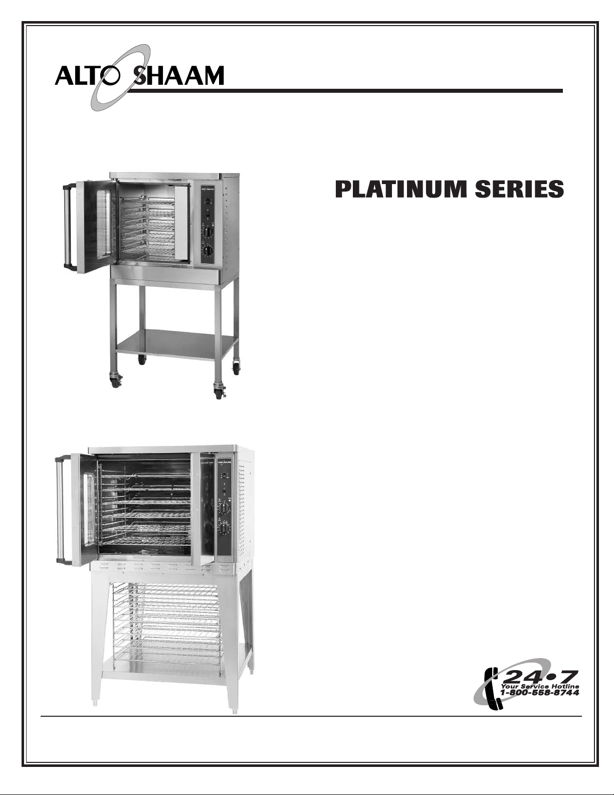
AS C- 2E
WI TH
Mobile Stand Option 5004687
C o n v e c t i o n O v e n
E l e c t r i c
Model:
ASC-2E
ASC-4E
AS C- 4E
WI TH
Stand Option 5003489
Manual
Control
• I N STALLATI O N
• OP E RAT ION
• MAI NT ENAN C E
W 1 6 4 N 9 2 2 1 W a t e r S t r e e t • P. O . B o x 45 0 • M e n o m o n e e F a l l s , W i s c o n s i n 5 3 0 5 2 - 0 4 5 0 U S A
PHONE: 262.251.3800 • 800.558.8744
P RI N TE D I N U . S .A .
USA/CANADA FAX: 262.251.7067 • 800.329.8744 U.S.A. ONLY
WEBSITE: www.alto-shaam.com
#87 01/ 2 • 11 /07
Page 2
D E L I V E R Y
®
®
U N PA C K I N G
his Alto-Shaam appliance has been
T
horoughly tested and inspected to insure only the
t
ighest quality unit is provided. Upon receipt,
h
heck for any possible shipping damage and
c
report it at once to the delivering carrier. Se e
Transportation Dam ag e and Claim s section located
in this manu al.
This appliance, complete with unattached
items and accessories, may have been delivered in
one or more packages. Check to ensure that all
standard items and options have been received
with each model as ordered.
Save all the information and instructions
packed with the appliance. Complete and return
the warranty card to the factory as soon as
possible to assure prompt service in the event of a
warranty parts and labor claim.
This manual must be read and understood by
all people using or installing the equipment
model. Contact the Alto-Shaam service
department if you have any questions concerning
installation, operation, or maintenance.
NO TE: All claims for warranty must include the
full model number and serial number of
the unit.
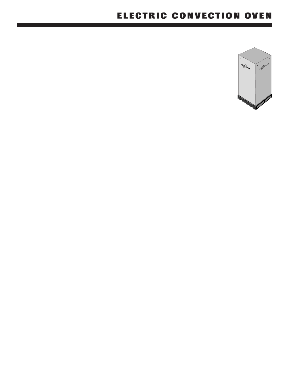
1. Carefully remove the
appliance from the
carton or crate.
OTE: Do not discard the
N
carton and other
packaging material
until you have
inspected the unit for
hidden damage and
tested it for proper
operation.
2. Read all instructions in this manual carefully
before initiating the installation of this appliance.
DO NOT DISCARD THIS M ANUAL.
This manual is considered to be part of the
appliance and is to be provided to the owner
or manager of the business or to the person
responsible for training operators. A d d itional
manuals are available from the Alto-Shaam
service dep artmen t.
3. Remove all protective plastic film, packaging
materials, and accessories from the appliance
before connecting electrical power. Store any
accessories in a convenient place for future use.
#8701/2 Electric Convection Oven - Manual Control • 1
Page 3
SAF ETY PROCEDURES
A N D P R E C A U T I O N S
nowledge of proper procedures is essential to the
K
afe operation of electrically energized equipment.
s
n accordance with generally accepted product
I
afety labeling guidelines for potential hazards,
s
he following signal words and symbols may be
t
sed throughout this manual.
u
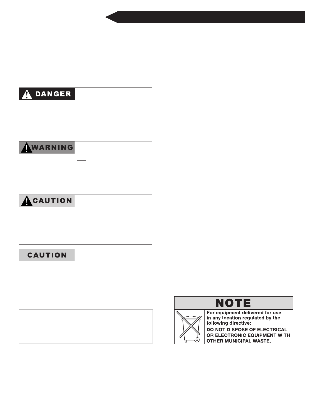
Used to indicate the
presence of a hazard that
cause severe personal
will
injury, death, or substantial
property damage if the
warning included with this
symbol is ignored.
Used to indicate the
presence of a hazard that
can cause personal injury,
possible death, or major
property damage if the
warning included with this
symbol is ignored.
Used to indicate the
presence of a hazard that
can or will cause minor or
moderate personal injury
or property damage if the
warning included with this
symbol is ignored.
1. This appliance is intended to cook, hold or
process foods for the purpose of human
consumption. No other use for this
appliance is authorized or recommended.
2. This appliance is intended for use in
commercial establishments where all
operators are familiar with the purpose,
limitations, and associated hazards of this
appliance. Operating instructions and
warnings must be read and understood by
all operators and users.
3. Any troubleshooting guides, component
views, and parts lists included in this manual
are for general reference only and are intended
for use by qualified technical personnel.
4. This manual should be considered a
permanent part of this appliance. This
manual and all supplied instructions,
diagrams, schematics, parts lists, notices, and
labels must remain with the appliance if the
item is sold or moved to another location.
NOTE:
Used to indicate the
presence of a hazard that
can or will cause minor
personal injury, property
damage, or a potential
unsafe practice if the
warning included with this
symbol is ignored.
Used to notify personnel of
installation, operation, or
maintenance information that is
important but not hazard related.
#8701/2 Electric Convection Oven - Manual Control • 2
Page 4

I N S T A L L AT I O N S A F E T Y W A R N I N G
®
METAL PARTS OFTHIS EQUIPMENT
BECOME EXTREMELY HOT WHEN IN
O
PERATION. TO AVOID BURNS,
ALWAYS USE HAND PROTECTION
WHEN OPERATING THIS APPLIANCE.
DO NOT store or use any
flammable liquids or allow
flammable vapors in the vicinity of
any appliance.
DO NOT LIFT OR MOVE THE
OVEN BY USING THE DOORS
OR THE DOOR HANDLES.
S I T E I N S T A L L A T I O N
This appliance must be
installed in a location that will
permit the oven to function
for its intended purpose and
to allow adequate clearance
for ventilation, proper
cleaning, and maintenance
access.
1. Hood installation is recommended. (
LO CAL CODE S
).
CH ECK
2. The oven must be installed on a stable and
level surface.
3. DO NOT install this oven in any area where it may
be affected by any adverse conditions such as steam,
grease, dripping water, high temperatures, etc.
4. DO NOT store or use any flammable liquids or
allow flammable vapors in the vicinity of this
oven or any other appliance.
5. This appliance must be kept free and clear of any
combustible materials.
6. This appliance must be kept free and clear of
any obstructions blocking access for maintenance
or service.
A S C - 2 E • W E I G H T
NET: 250 lb (113 kg) EST. SHIP: 325 lb ( 147 kg) EST.
CRATE 44" H X 42" W X 42" D
D I M E NSI O N S: (1118mm x 1067mm x 1067mm)
MINIMUM ENTRY CLEA RANCE 31" (787mm) UNCRATE D
A S C - 2 E • D I M E N S I O N S : H x W x D
EXTERIOR: 32-1/8" x 30" x 30-1/8" (815mm x 762mm x 815mm)
INTE RIOR: 20" x 15" x 21" (508mm x 381mm x 533mm)
A S C - 4 E • W E I G H T
NET: 393 lb (178 kg) EST. SHIP: 438 lb ( 199 kg)
CRATE 40" H X 44" W X 53" D
D I M E NSI O N S: (1016mm x 1118mm x 1346mm)
MIN. ENTRY CLE ARANCE 31-1/2" (800mm) UNCRATED
W/O L EGS
A S C - 4 E • D I M E N S I O N S : H x W x D
EXTERIOR: 57-1/2" x 38" x 44-1/2" (1461mm x 965mm x 1130mm)
INTE RIOR: 24" x 29-1/8" x 25" (610mm x 740mm x 635mm)
Where automatically operated appliances are vented
through a ventilating hood or exhaust system
equipped with a damper or with a power means of
exhaust, provisions shall be made to allow the
equipment to operate only when the damper is open
to a position to properly vent the appliance and
when the power means of exhaust is in operation.
A CCORD ANCE WI TH NF PA 5 4 CO MM ON WEAL T H O F
M ASSAC HUSE TTS ONLY
.
#8701/2 Electric Convection Oven - Manual Control • 3
M I N I M U M C L E A R A N C E R E Q U I R E M E N T S
BA CK 0" (0mm)
LE FT SI DE 2" (51mm)
RI GH T SID E 2" (51mm)
FROM GREASE PRODUCING EQUIPMENT 6" (152mm)
RE CO MM EN DE D SER VI CE ACC ES S: 20" (508mm) RI GHT SI DE
Page 5
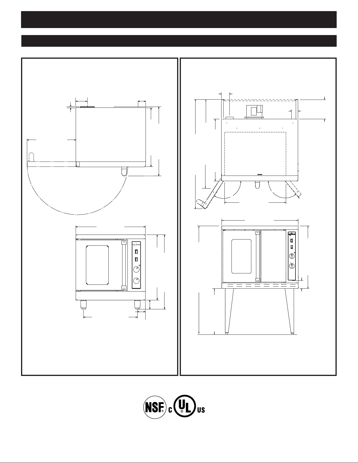
30-5/8" (778mm)
8" (203mm)
CAVITY VENT
ELECTRICAL
I
NLET
3-5/32"
(80,1mm)
9-15/16" (252mm)
ELECTRICAL ENTRANCE
1
23?
129?
29" (737mm)
CAVITY WIDTH
38" (965mm)
31-1/16" (789mm)
4" (102mm)
ELECTRICAL INLET
54-5/8" (1387mm)
44-1/2" (1130mm)
26-
1/
2"
(
673mm)
57-1/2" (1461mm)
30" (762mm)
28-3/16" (715mm)
3-15/16" (100mm)
32-1/8" (815mm)
3-3/8" (86mm)
23-1/4" (590mm)
4-11/16"
(
119mm)
1"
(25mm)
21-1/8 (536mm)
3-1/4"
(
83mm)
25-7/16 (646mm)
30-1/8" (815mm)
Exhaust
E
lectrical
2
" (51mm)
from bottom
I N S TA L L A T I O N
E X T E R I O R D I M E N S I O N S
A S C - 2 E A S C - 4 E
LISTED
#8701/2 Electric Convection Oven - Manual Control • 4
COOKING APPLIANCE
49ZA
Page 6
I N S T A L L A T I O N
TO PREVENT PERSONAL INJURY,
USE CAUTION WHEN MOVING OR
LEVELING THIS APPLIANCE.
I N S T A L L AT I O N R E Q U I R E M E N T S
A number of adjustments are associated with
initial installation and start-up. It is important
that these adjustments be conducted by a qualified
service technician. Installation and start-up
adjustments are the responsibility of the dealer or
user. These adjustments include but are not
limited to thermostat calibration, door adjustment,
leveling, and moisture vent installation.
All clearances for proper ventilation air supply
must be maintained to minimize fire hazard. Do
not locate the oven immediately adjacent to any
other heat generating appliance.
Inadequate ventilation may
result in a high ambient
temperature at the rear of the oven. An excessive
ambient temperature can cause the thermaloverload protection device on the blower motor to
trip resulting in severe damage to the blower
motor.
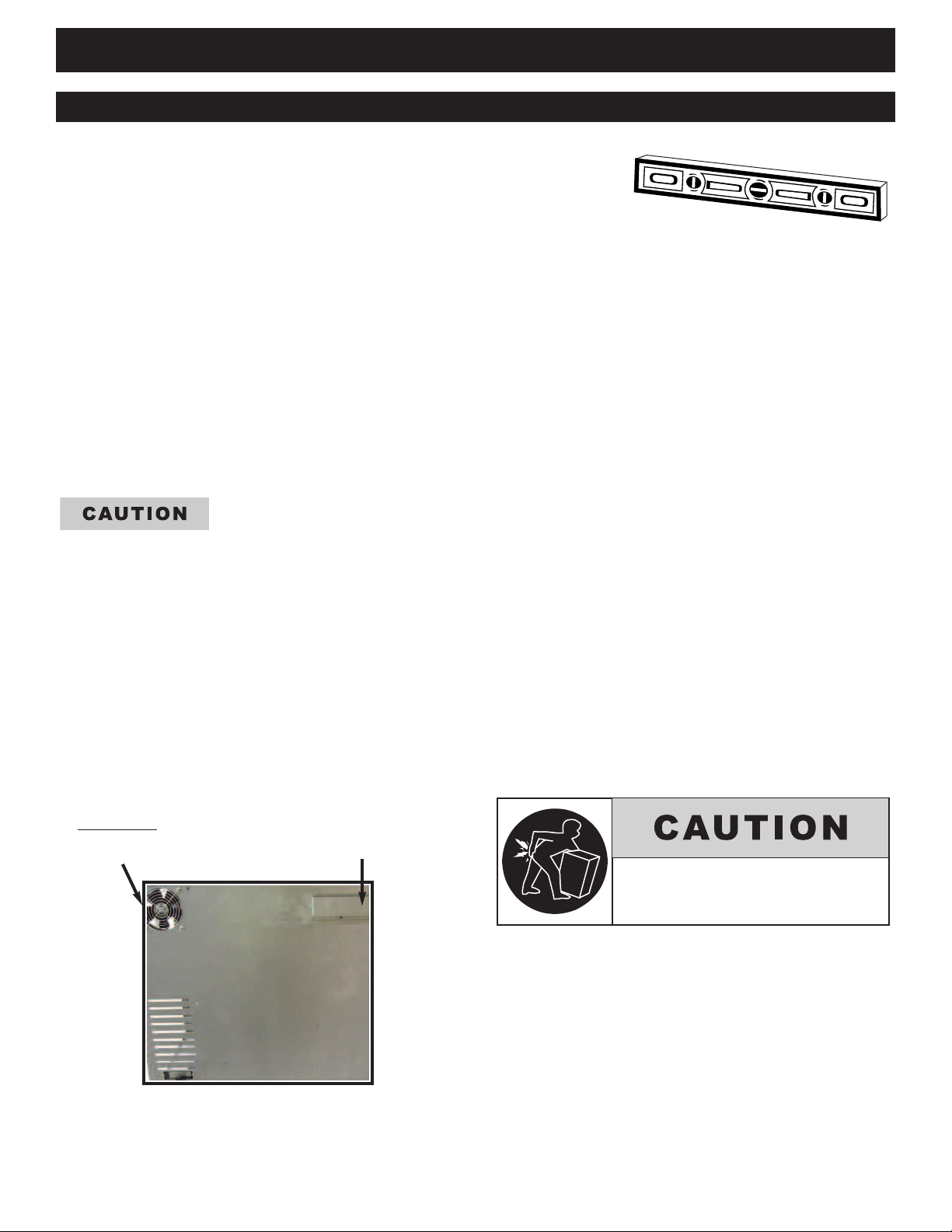
LEV ELING
Level this appliance from sideto-side and front-to-back with the use of a spirit
level. For ovens installed on a mobile stand, it is
important that the installation surface be level due
to the probability of frequent oven repositioning.
We recommend checking the level of the appliance
periodically to make certain the floor has not
shifted nor the appliance moved.
NOTE: Failure to properly level this oven can
cause improper function and will result
in the uneven baking of products
consisting of semi-liquid batter.
CO OL ING FAN
FA-3568
FAN GUA RD
GD-2396
MOISTUR E
VENT
ON BACK OF
OVEN
#8701/2 Electric Convection Oven - Manual Control Pg. 5.
Page 7
I N S TA L L A T I O N
I N S T A L L AT I O N R E Q U I R E M E N T S
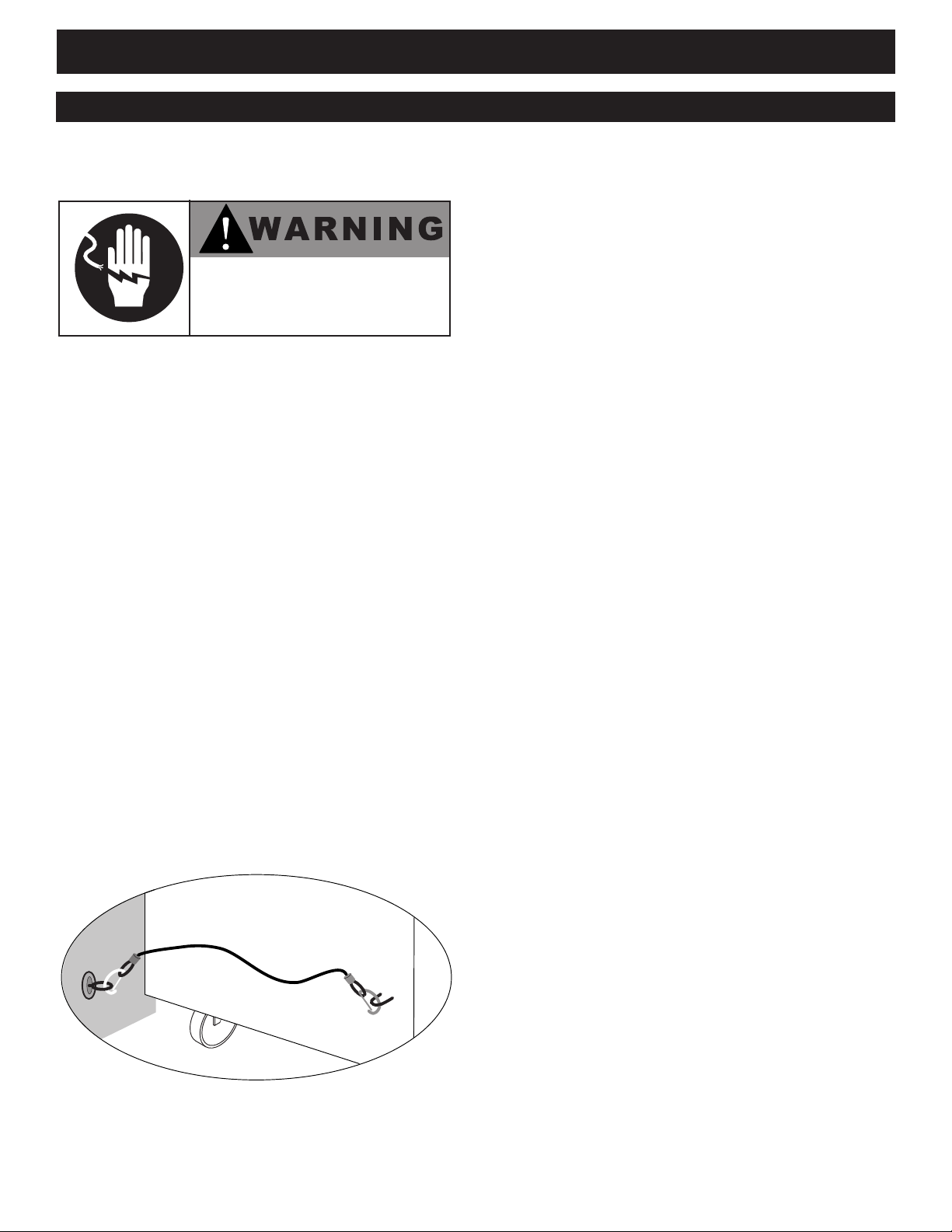
RESTRAINT REQUIREMENTS
—MOBILE EQUIPMENT
RISK OF ELECTRIC SHOCK.
Appl iance must be secured
to build ing structure.
Any appliance that is not furnished with a power
supply cord but includes a set of casters must be
provided with a tether. Adequate means must be
provided to limit the movement of this appliance
without depending on or transmitting stress to the
electrical conduit. The following requirements
apply:
1. Casters must be a maximum height of
6" (152mm).
2. Two of the casters must of be the
locking type.
3. Such mobile appliances or appliances on
mobile stands must be installed with the
use of a flexible connector secured to the
building structure.
A mounting connector for a restraining device is
located on the lower back flange of the appliance
chassis or on an oven stand, approximately 18"
(457mm) from the floor. A flexible connector is
not supplied or available from the factory.
#8701/2 Electric Convection Oven - Manual Control • 6
Page 8
I N S TA L L A T I O N
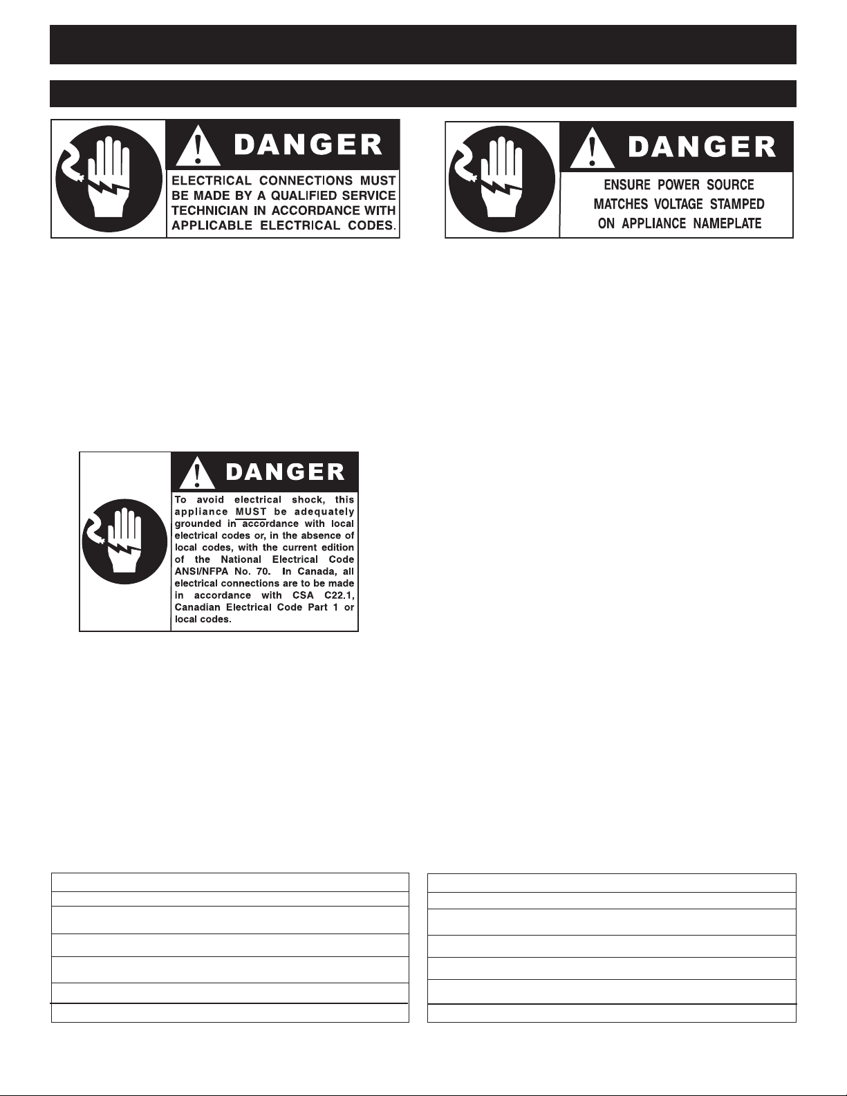
E L E C T R I C A L C O N N E C T I O N
The oven must be installed by a qualified
electrician. This appliance must be branch circuit
protected with proper ampacities, in accordance
with the wiring diagram located in this manual or
in the electrical compartment of the oven. The
oven must be properly grounded in accordance
with the National Electrical Code and applicable
local codes.
Plug the unit into a properly grounded receptacle
ONLY, positioning the unit so that the plug is
easily accessible in case of an emergency. Arcing
will occur when connecting or disconnecting the
unit unless all controls are in the “off” position.
Proper receptacle or outlet configuration or
permanent wiring for this unit must be installed
by a licensed electrician in accordance with
applicable local electrical codes.
Wire size for the main incoming power to the
unit must match the minimum size listed in the
specifications applicable to the specific oven
model. For supply connections, locate the wire
size posted on the label located near the electric
terminal block behind the service panel or
elsewhere listed in this manual. Before
attempting the electrical connection, the rating
plate should be checked to ensure that the
electrical characteristics of the appliance and the
electrical supply characteristics agree.
Installation of the wiring must be made in
accordance with U.L. 197 Commercial Electric
Cooking Appliance Standards, Local and/or
National Electrical Code, ANSI /NFPA 70-1990.
Service line entry is made through the rear of the
oven for connection to the terminal block.
Remove the service panel on the right side of the
oven for access to the terminal block.
The oven is wired at the factory for either single
phase or three phase service as indicated on the
original purchase order. Input voltage and phase
must match the voltage and phase of the oven.
Visually check all electrical connections.
E L E C T R I C A L • A C S - 2 E
VOLTAGE PHASE CYCLE/ HZ AWG AMPS kW
208 1 50/60 10 25.5 5.3
240 1 50/60 10 22.0 5.3
208 3 50/60 12 14.7 5.3
240 3 50/60 12 12.8 5.3
N O CO RD A N D P L U G
#8701/2 Electric Convection Oven - Manual Control Pg. 7.
E L E C T R I C A L • A S C - 4 E
VOLTAGE PHASE CYCLE/ HZ AWG AMPS kW
208 1 50/60 6 50.0 10.4
240 1 50/60 6 43.3 10.4
208 3 50/60 8 25.0 10.4
240 3 50/60 8 25.0 10.4
N O CO RD A N D P L U G
Page 9
I N S TA L L A T I O N
TO PREVENT PERSONAL INJURY,
USE CAUTION WHEN MOVING OR
LEVELING THIS APPLIANCE.
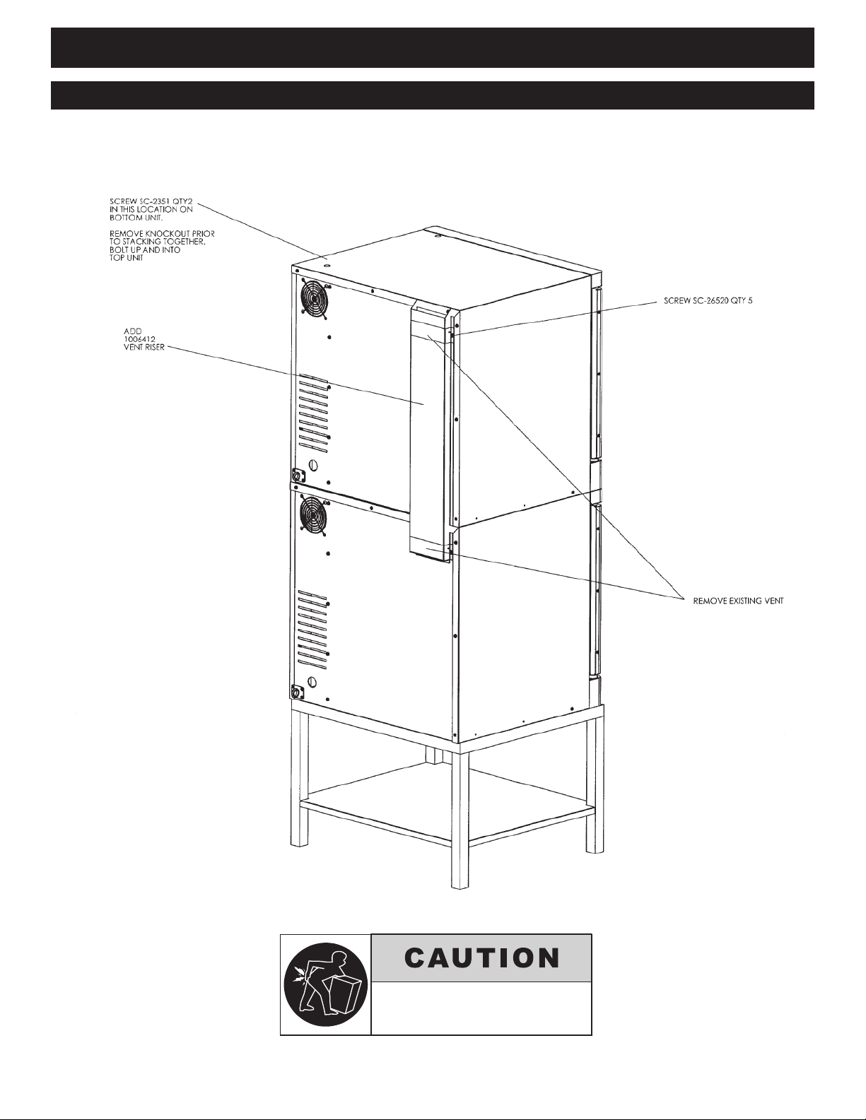
S T A C K I N G & V E N T I N G A S S E M B L Y f o r 2 - A S C - 2 E / S T K
#8701/2 Electric Convection Oven - Manual Control • 8
Stand
#5004672
2 - A S C - 2 E / S T K
Page 10

I N S TA L L A T I O N
2
3
Remove top elbow
vent prior to
installing riser.
Assemble venting
components
2 and 3 as shown.
2 1004984 RISER, FLUE ELECTRIC 1
3 SC-26520 SCREW, #10 SMS .5LG 5
Item No. Part No. Description Qty.
After legs or casters have been installed
on the bottom oven, place the upper oven
on top of lower unit. Align.
TO PREVENT PERSONAL INJURY,
USE CAUTION WHEN MOVING OR
LEVELING THIS APPLIANCE.
S T A C K I N G & V E N T I N G A S S E M B L Y f o r 2 - A S C - 4 E / S T K
2 - A S C - 4 E / S T K
#8701/2 Electric Convection Oven - Manual Control • 9
Page 11

I N S TA L L A T I O N
d
a
b
i
b
c
g
a
f
b
e
h
a
34-5/16" (872mm)
38" (965mm)
44-3/16" (1122mm)
O V E N S T A N D A S S E M B L Y - A S C - 4 E
A S C - 4 E
ITEM NO PART NUMBER DESCRIPTION QTY.
1 5003488 Leg Support Assembly 2
2 1004459 Channel, Support 2
3 LG-22185 Leg 4
CS-25474 Casters, rigid 2
CS-25674 Casters, swivel w/brake 2
4 1004461 Bracket, Stand 1
5 1004369 Bracket, Attachment 2
6 1004460 Channel, Back 1
7 1004466 Shelf, Stand 1
8 SR-26551 Rack, Oven Support 2
9 SH-26395 Oven Rack 6
10 SC-22729 Screws, 1/4-20 x 1/2 Hex Head 27
11 NU-23984 Net, 1/4-20 Nylon Insert, 18-8 S/S 27
12 WS-2294 Washer 27
#8701/2 Electric Convection Oven - Manual Control • 10
Page 12

O P E R A T I N G I N S T R U C T I O N S
U S E R S A F E T Y I N F O R M AT I O N
S T A R T- U P O P E R A T I O N
This appliance is intended for use in commercial
stablishments by qualified operating personnel
e
where all operators are familiar with the
purpose, limitations, and associated hazards of
this appliance. Operating instructions and
warnings must be read and understood by all
operators and users.
BEFOR E INITIAL USE:
Interior oven surfaces must be heated to remove
surface oils and the accompanying odor
produced during the first use of the oven.
1. Wipe all wire shelves, side racks and the full
oven interior with a clean, damp cloth.
O P T I O N S & A C C E S S O R I E S • A S C - 2 E
LEG KIT, 4" (102mm)
Seismic feet . . . . . . . . . . . . . . . . . . . . . . . . . . . . . . . . .5004688
■■
LEG KIT
■■
with Bullet feet, 19-1/2" (495mm) HEIGHT . . . . . . . . .5005169
with Seismic feet, 19-1/2" (495mm) HEIGHT . . . . . . .5005168
■■
with Casters, 23" (584mm) HEIGHT . . . . . . . . . . . . . . .5005181
■■
■■
SHELF, OVEN RACK . . . . . . . . . . . . . . . . . . . . . . . .SH-26894
STACKING HARDWARE
SEE INDIVIDUAL STACKING COMBINATION SPECIFICATION SHEETS
STAND, SINGLE OVEN
with Bullet feet, 26-1/2" (673mm) HEIGHT . . . . . . . . .5004672
■■
with Seismic feet, 26-1/2" (673mm) HEIGHT . . . . . . .5005172
■■
■■
with Casters, 30" (762mm) HEIGHT . . . . . . . . . . . . . . .5004687
O P T I O N S & A C C E S S O R I E S • A S C - 4 E
■■
CASTER SET, 6" (152mm) 5003790
COOLING RACK FOR OVEN STAND 5003791
■■
LEG SET (4)
6" (152mm) with Bullet Feet 5003794
■■
■■
6" (6152mm) with Seismic Feet 5003795
■■
25" (635mm) with Seismic Feet 5003785
■■
PANEL FOR BACK, Stainless Steel 5005876
SHELF, OVEN RACK
INTERCHANGEABLE WITH COOLING RACK SH-26795
■■
STACKING HARDWARE
SEE INDIVIDUAL STACKING COMBINATION SPECIFICATION SHEETS
STAND, STAINLESS STEEL
■■
Mobile, with Cooling Racks & Casters, 38" H (965mm)5003786
Stationary, with Cooling Racks & Bullet Feet 5003489
■■
Stationary, with Cooling Racks & Seismic Feet 5003787
■■
34-1/4" (870mm) min. • 35-1/2" (902mm) max. H
#8701/2 Electric Convection Oven - Manual Control Pg. 11.
(FEET ARE ADJUSTABLE)
2. Close the oven doors, press the power
N
O
switch to the
position, and set the
thermostat to 300°F (149°C).
3. Allow the oven to cycle for approximately
2 hours or until no odor is detected.
PR EHE ATIN G:
Always preheat a cold oven for a minimum of
20 minutes before cooking product. Follow
the operating instructions indicated on the next
few pages of this manual.
IN THE EVE NT O F A POWER FAILURE:
• TURN ALL SWITCHES OFF.
• WAIT UNTIL POWER IS RESTORED BEFORE
ATTEMPTING TO OPERATE THE OVEN.
NOTE: If su ch an event has occurred, it is strong ly
recomme nded that you ensure the food in the ov en
is safe for consump tion according to local health
regulations.
A S C - 2 E • P R O D U C T \ PAN C A PA C I T Y
27 lb (12 kg) MAXIMU M — 17 qts (15 liters)
Nine (9): 18" x 13" x 1" HAL F-SIZ E SHEET PANS
5 chrome plated wire shelves with 2 removable side
racks and 9 shelf positions spaced
at 1-5/8" (41mm) ea.
A S C - 4 E • P R O D U C T \ PAN C A PA C I T Y
72 lb (33 kg) MAXIMU M — 45 qts (43 liters)
Twelve (12): 18" x 26" x 1" FUL L-SIZE S HEET PANS
6 chrome plated wire shelves with 2 removable side
racks and 12 shelf positions spaced
at 1-3/4" (43mm) ea.
Page 13

O P E R A T I N G I N S T R U C T I O N S
METAL PARTS OF THI S EQUIPMENT
BECOME EXTREMELY HOT WHEN IN
OPERATION. TO AVO ID BURNS,
ALWAYS USE HAND PROTECTION
WHEN OPERATING THIS APPLIANCE.
U S E R I N F O R M A T I O N
PAN /SH ELF POSITIONS FO R AS C-2 E:
The oven includes 5 chrome plated wire
shelves with two removable side racks and
shelf positions spaced at 1
9
-
5/8
"
(41mm).
POSITION
. The best arrangement for broiling, baking
1
2
cookies and for other baked goods under
4
-1/
" (65mm) in height. This arrangement can
2
6
8
POSITION
2. General baking with the use of sheet pans for
1
4
7
POSITION
3. Ideal positions for baking bread, meringue, or
1
5
4. Arrangement necessary for roasting whole
POSITION
1
2
also be used as the maximum capacity for
reconstituting frozen entrées.
products under 3-
1
/
" (89mm) in height.
2
Products include cakes, pies, muffins, or
extended dishes in 12" x 20" x 2-
(530mm x 325mm x 65mm GN
1
/
" deep pans
2
1
).
/
1
extended dishes and roasts in pans not to
1
exceed 5-
/
" (140mm) in height.
2
turkey or roasts up to 7" (178mm) in height.
6
PAN /SH ELF POSITIONS FO R AS C-4 E:
The oven includes 6 chrome plated wire
shelves with two removable side racks and
12 shelf positions spaced at 1-
3
/
" (43mm).
4
POSITION
1. The best arrangement for broiling,
2
4
6
8
10
12
POSITION
2. General baking with the use of sheet
1
4
7
10
POSITION
3. Ideal positions for baking bread,
1
5
9
POSITION
4. Arrangement necessary for roasting
1
6
baking cookies and for other baked
1
" (65mm) in height.
goods under 2-
/
2
This arrangement can also be used as
the maximum capacity for
reconstituting frozen entrées.
1
/
pans for products under 3-
"
2
(89mm) in height. Products include
cakes, pies, muffins, or extended
1
/
dishes in 12" x 20" x 2(530mm x 325mm x 65mm GN
" deep pans
2
1
/
).
1
meringue, or extended dishes and
1
/
roasts in pans not to exceed 5-
"
2
(140mm) in height.
whole turkey or roasts up to 7"
(178mm) in height.
#8701/2 Electric Convection Oven - Manual Control • 12
Page 14

O P E R A T I N G I N S T R U C T I O N S
MANUAL CONTROL OPERATION
1. Press POWER SWITCH to the ON position.
2. Press FAN SWITCH to high or low fan speed.
3. Set COOK TEMPERATURE THERMOSTAT
to the temperature desired.
When this temperature is reached,
LIGHT OFF\OVEN READY indicator light
will go out.
ALLOW A MINIMUM OF 20 MINUTES
TO PREHEAT A COLD OVEN.
4. Load product into the oven.
For best results, always load the oven from the
bottom to the top position and load as quickly as
possible to retain maximum oven compartment heat.
5. Set COOK TIMER by rotating the knob
clockwise past the time required and then back to
the desired time.
The timer will begin to count down. When the
timer reaches zero, the oven will produce an audible
alert signal that will continue for three minutes or
until the timer knob is turned counterclockwise to
the OFF position.
COOL-DOWN MODE
1. Press POWER SWITCH to
the COOL DOWN position.
2. Open the oven doors.
SHUT-DOWN PROCEDURE
1. Press POWER SWITCH
to the OFF position.
#8701/2 Electric Convection Oven - Manual Control • 13
Page 15

C H E F O P E R AT I N G T I P S
he Alto-Shaam convection oven will provide the best results and longest possible
T
service with the utilization of the following suggestions and guidelines.
NOTE: Moisture will escape around the doors when baking products with a heavy
moisture content such as chicken, potatoes, etc. This is a normal operating
ondition.
c
1. Preheat a cold oven for a minimum of 20 minutes
before use.
2. As a general rule, the cooking temperature can be
set lower than the temperature used in a
conventional oven. Cooking time may also be
shorter. It is suggested the first batch of each
product prepared be monitored closely to check for
variances.
3. Maintain a record of the temperatures, times, and
load capacities established for products cooked on
a regular basis since they will be the same or
similar for succeeding loads.
4. When practical, start cooking the lowest
temperature products first and gradually work up
to products with a higher cooking temperature.
5. If the cooking temperature setting for the previous
product is more than 10°F (5°C to 6°C) higher than
the temperature needed for the next load, use the
COOL-DOWN feature to decrease the oven
temperature before setting the oven to a lower
temperature.
6. Work as quickly as possible when loading the oven
to prevent heat loss.
7. When the audible signal indicates the time has
expired, remove the product from the oven as
quickly as possible to avoid over-cooking.
8. Pan s sh ould be centered b etween side rac ks a nd
each shelf should be l oad ed evenly to allow
prope r ai r circu lation within the oven
compartme nt.
9. To assure even cooking when baking, weigh or
measure the product in each pan.
10 . ASC-2E:
When cooking five pans of product, start from the
bottom of the oven and use side rack positions 1, 3,
5, 7, and 9.
AS C-4 E:
When cooking six pans of product, start
from the bottom of the oven and use side rack
positions 2, 4, 6, 8, 10, and 12.
11 . Do not overload the oven. Refer to product/pan
capacities indicated in this manual.
12 . To obtain the most evenly baked product, muffin
pans should be placed in the oven with the short
side of each pan facing the front of
the oven.
13 . When rethermalizing frozen casseroles, preheat
the oven 100°F (38°C) over the suggested
temperature to compensate for the introduction of
a large quantity of frozen product into the oven
compartment. Reset the thermostat to the correct
cooking temperature after the oven is loaded.
14. Use a pan extender or two inch (51mm) deep,
18” x 26” pans for batter-type products that weigh
more than 8 pounds (3 to 4 kg), i.e.; pineapple
upside-down cake.
15. To avoid obstructing airflow that would result in
uneven cooking results, never place anything
directly on the bottom of the oven cavity.
AT T H E E N D O F T H E DAY, U T I L I Z E T H E
C O O L - D O W N M O D E . S H U T O F F
P O W E R O N T H E CO O L E D O V E N
B E F O R E L E A V I N G .
Cooking Guidelines
F° Minutes
Food Temperature /Time
Cakes, Sheet 325° 25
Chicken pieces 400° 25
30 breasts & thighs, 25 legs & wings
Chicken halves 400° 40
Beef patties 400° 8
Bacon 350° 16
Fish, frozen (5 oz.) 350° 15
Macaroni & Cheese, frozen, 1 pan 350° 50
Macaroni & Cheese, frozen, full oven 350° 90
Macaroni & Cheese, refrigerated 350° 30
Muffins 325° 13-15
Pies, Frozen 325° 40
Pizzas, Individual 325° 15
Potatoes, Baked 350° 50
Sandwiches, Grilled Cheese 400° 4-6
Tater tots 450° 10
Do not place anything directly
on the bottom of the oven cavity.
#8701/2 Electric Convection Oven - Manual Control • 14
Page 16

C L E A N I N G A N D P R E V EN T I V E M A IN T E N A N C E
PROTECTING STAINLESS STEEL SURFACES
It is important to guard against
corrosion in the care of stainless
steel surfaces. Harsh,
corrosive, or inappropriate
chemicals can completely
destroy the protective surface
layer of stainless steel. Abrasive pads, steel wool,
or metal implements will abrade surfaces causing
damage to this protective coating and will
eventually result in areas of corrosion. Even water,
particularly hard water that contains high to
moderate concentrations of chloride, will cause
oxidation and pitting that result in rust and
corrosion. In addition, many acidic foods spilled
and left to remain on metal surfaces are
contributing factors that will corrode surfaces.
Proper cleaning agents, materials, and
methods are vital to maintaining the appearance
and life of this appliance. Spilled foods should be
removed and the area wiped as soon as possible
but at the very least, a minimum of once a day.
Always thoroughly rinse surfaces after using a
cleaning agent and wipe standing water as quickly
as possible after rinsing.
CLEANING AGENTS
Use non-abrasive cleaning products designed for use
on stainless steel surfaces. Cleaning agents must be
chloride-free compounds and must not contain
quaternary salts. Never use hydrochloric acid
(muriatic acid) on stainless steel surfaces. Always
use the proper cleaning agent at the manufacturer's
recommended strength. Contact your local cleaning
supplier for product recommendations.
CLEANING MATERIALS
The cleaning function can
usually be accomplished
with the proper cleaning
agent and a soft, clean
cloth. When more
aggressive methods must be
employed, use a non-abrasive
scouring pad on difficult areas
and make certain to scrub with the
visible grain of surface metal to avoid surface
scratches. Never use wire brushes, metal scouring
pads, or scrapers to remove food residue.
#8701/2 Electric Convection Oven - Manual Control • 15
Page 17

C L E A N I N G A N D P R E V EN T I V E M A IN T E N A N C E
The oven is fabricated with an easy to clean
porcelain enamel interior or an optional stainless
steel interior.
NOTE: Always allow the oven to cool before
cleaning. If the oven is hot, allow the
interior surfaces to become cool to the
touch by using the cool-down mode and
opening the oven door(s).
C L E A N T H E O V E N O N A D A I LY B A S I S .
AT NO TIME SHO ULD THE OVEN INTERIOR OR
XTE RIOR BE S TEAM CLE A NED, HOS E D
E
DOWN, OR F LOODED WITH ANY TYP E O F
IQUI D. DO NOT U SE A WATER JE T TO CL EAN.
L
S E V E R E D A M A G E O R E L E C T R I C A L
HAZARD C O U L D R E S U LT. SUCH METHODS
WILL ALSO VOID ANY WARRANTY CLAIMS.
NOTE: DO NO T USE ABR ASIVE CL EANIN G
CO MPOUN DS.
Completely avoid the use of
abrasive cleaning compounds, chloride-based
cleaners, or cleaners containing quaternary salts.
To protect metal finish on stainless steel, never use
hydrochloric acid (muriatic acid).
1. After the oven has cooled, remove all detachable
items such as wire shelves, side racks, and any drip
pan. Clean these items separately.
2. Remove any food scraps from shelves, shelf
supports, and blower fan wheel. Convection
baffle openings must be kept clear of food scraps
and grease.
3. Wipe the interior metal surfaces of the oven
with a paper towel to remove any remaining
food debris.
4. Clean interior with a damp cloth or sponge and
any good commercial detergent at the
recommended strength.
5. For baked-on food deposits, use a non-caustic and
non-toxic commercial oven cleaner appropriate for
the interior oven surface of the oven. Follow the
product manufacturer's instructions carefully for
the use of this product. Any commercial oven
cleaner must be approved for use on food contact
areas. Remove soil with the use of a plastic
scouring pad.
6. Wipe door gaskets, control
panel, door vents, and door
handle thoroughly since these
areas harbor food debris
and grease.
7. Rinse surfaces by wiping with a clean cloth or
sponge and clean warm water.
8. Remove excess water with a sponge and wipe dry
with a clean cloth or air dry. Leave doors open
until interior is completely dry. Replace side racks
and shelves.
Always follow appropriate state or local health
(hygiene) regulations regarding all applicable cleaning
and sanitation requirements for food service
equipment.
6. Wipe door gaskets, control panel, door vents, and
door handle thoroughly since these areas harbor
food debris and grease.
7. Rinse surfaces by wiping with a clean cloth or
sponge and clean warm water.
#8701/2 Electric Convection Oven - Manual Control • 16
AT T H E E N D O F T H E DAY, U T I L I Z E T H E
C O O L - D O W N M O D E . S H U T O F F
P O W E R O N T H E CO O L E D O V E N
B E F O R E L E A V I N G .
Page 18

C L E A N I N G A N D P R E V EN T I V E M A IN T E N A N C E
E X T E R I O R :
To help maintain the protective film coating on
polished stainless steel, clean the exterior of the
cabinet with a cleaner recommended for stainless
steel surfaces. Spray the cleaning agent on a clean
loth and wipe with the grain of the stainless steel.
c
Wipe control panel, door vents and door handles,
thoroughly since these areas harbor food debris.
Clean exterior glass surfaces with a commercial
window cleaner.
D O N O T U S E A B R A S I V E C L E A N I N G
C O M P O U N D S .
M O T O R C A R E
The convection oven motor contains selflubricating, sealed ball bearings and is generally
aintenance-free. During operation, the interior
m
of the motor is cooled by air flowing into the rear
of the motor case. This is a general operating
feature when proper clearances have been
allowed.
AT T H E E N D O F T H E DAY, U T I L I Z E T H E
C O O L - D O W N M O D E . S H U T O F F
P O W E R O N T H E CO O L E D O V E N
B E F O R E L E A V I N G .
T R O U B L E S H O O T IN G G U I D E
Oven has no power. Check to ensure oven is connected to proper power source.
Check that breaker is turned on.
Fuses are blown.
Oven has power but will not turn ON . Ensure power switch is turned on.
Ensure hi limit is not tripped.
Ensure doors are closed.
Ensure timer is turned on.
Ensure fan switch is turned on.
Door switch is bad or out of adjustment.
Oven fan turns ON , but there is no heat. Ensure thermostat is turned on.
Ensure hi-limit is not tripped.
Oven heats, fan runs, but doesn’t
shut OFF when door is opened. Door switch is bad or out of adjustment.
#8701/2 Electric Convection Oven - Manual Control • 17
Page 19

S E R V I C E - A S C- 2 E
ervice must be in accordance with all
S
local codes and must be performed by
a qualified service technician.
DOOR ASSEMB LY
5004352
SIDE RACK (2 PCS)
SR-2689 3
OVEN SHELF (5 PCS )
SH-2689 4
DOOR ROLLER
ASSEMBLY
DOOR ROLLER
ASSEMBLY
KNOB, CONTR OL ( 2 PCS)
KN-3410 3
PANEL OVER LAY
PE-2697 8
SWITCH,
ON/OFF COOL -DOWN
SW-3411 2
SWITCH,
FAN, HI/LO
SW-3410 1
INDICATOR LIGHT
LI-3951
THERMOS TAT
TT-3409 2
TIMER
TR-3417 4
GASKET
TOP & BOTTOM 1005 316
SIDES 10053 11
STAND, MOB ILE
(O PT ION AL) 5004 68 7
ASC-2E
#8701/2 Electric Convection Oven - Manual Control • 18
Page 20

S E R V I C E - A S C - 2 E
I N T E R I O R O V E N C O M P A R T M E N T
MO TO R
MO-3420 8
SI DE RAC K
SR-2689 3
SH EL F
SH-2689 4
NO T SHOW N
ASC-2E
oven interior
BA FF LE
5005074
GASKET
TOP & BOTTOM 1005 316
SIDES 10053 11
#8701/2 Electric Convection Oven - Manual Control • 19
Page 21

R I G H T S I D E S E R V I C E PA N E L - R E M O V E D
UL B/REC EP TACL E
B
LP-3686
RP-3986
N/OFF SWI TC H
O
SW-3411 2
FAN SWI TC H
SW-3410 1
S E R V I C E - A S C - 2 E
EAT ELE ME NTS
IG H LIMI T
H
SW-3415 0
H
EL-3421 1
EL-3421 2
, 20 8V
IN DI CATO R LIGHT
LI-3951
TH ER MOS TAT
TT-3409 2
TR-3417 4
TE RM INA L BLOCK
BK-3597
TI ME R
HI GH LIM IT
SW-3350 0
MO TO R
MO-3420 8
LO W LIMI T
SW-3337 8
MO TO R PR OTECTI ON
SW IT CHE S
ASC-2E
#8701/2 Electric Convection Oven - Manual Control • 20
FAN HOU SI NG
FA-3568
Page 22

S E R V I C E - A S C- 4 E
ervice must be in accordance with all
S
local codes and must be performed b y a
q u a l i f i e d s e r v i c e t e c h n i c i a n .
DOOR ASSEMB LY, L H
5005407
SIDE RACK (2 PCS)
SR-2639 6
OVEN RACK (6 PCS)
SH-2639 5
TOP & BOTTOM 6606
SIDES 6605
PANEL OVER LAY
PE-2672 9
SWITCH,
ON/OFF COOL -DOWN
SW-3411 2
SWITCH,
FAN, HI/LO
SW-3410 1
INDICATOR LIGHT
LI-3951
THERMOS TAT
TT-3409 2
KNOB, THERM OSTAT
KN-3429 7
TIMER
TR-3417 4
KNOB, TIMER C ON TROL
KN-3410 3
DOOR ASSEMB LY, R H
5005409
GASKETS
STAND, STATIONA RY
(O PT ION AL) 5003 48 9
SIDE RACK
SUPPORT ( 2 PC S)
SR-2655 1
ASC-4E
#8701/2 Electric Convection Oven - Manual Control • 21
Page 23

S E R V I C E - A S C - 4 E
I N T E R I O R O V E N C O M P A R T M E N T
LE ME NT
E
RE AR EL-341 26
MI DD LE E L-34127
RO NT
F
, 20 8V
EL-3412 8
LI GH T RE CEPTACL E
LP-3416 1
SI DE RAC K
SR-2639 6
ASC-4E
oven interior
BL OW ER W HEEL
WH-2640 5
#8701/2 Electric Convection Oven - Manual Control • 22
TH ER MOS TAT
GU AR D
1004611
Page 24

N/OFF SWI TC H
O
SW-3411 2
S E R V I C E - A S C - 4 E
R I G H T S I D E S E R V I C E PA N E L - R E M O V E D
OT OR PRO TEC TION
BU LB /RE CEP TACL E
LP-3686
RP-3986
HIGH SW-335 00 LOW SW-333 78
M
SW IT CHE S
FAN SWI TC H
SW-3410 1
TH ER MOS TAT
TT-3409 2
TI ME R
TR-3417 4
HI GH LIM IT
SW-3415 0
TE RM INA L BLOCK
BK-3597
ASC-4E
#8701/2 Electric Convection Oven - Manual Control • 23
Page 25

UX IL IAR Y
A
AN
F
S E R V I C E - A S C - 4 E
R E A R P A N E L - R E M O V E D
OI ST URE
M
EAT
H
LE ME NTS
E
VE NT
EL EC TRI CAL
CO NN ECT ION
MO TO R
MO-3421 5
ASC-4E
#8701/2 Electric Convection Oven - Manual Control • 24
Page 26

S E R V I C E PA RT S L I S T
Description ASC-2E ASC-4E
Part No.Part No. Qty.
Cosmetic/Exterior Components
Panel, Top and Side 1005455 1006623 1
Gasket, LH/RH 1005311 1006605 2
Gasket, Top/Bottom 1005316 1006606 2
Panel, Service, louvered 1006602 1006672 1
Cover, Bottom 1005458 1006678 1
Cover, Top 1005459 1006679 1
Interior
Rack, Side SR-26893 SR-26396 2
Shelf SH-26894 SH-26795 5 / 6
Lamp, *CT, snap-in, oven light -- LP-34161 2
Gasket, oven lamp -- GS-26630 2
Glass, *CT, oven lamp -- GL-26608 2
Cover for oven light -- CV-26607 2
Receptacle, Lamp -- RP-3986 1
Oven Elements
Element, Outer, 208V EL-34211 -- 1
Element, Inner, 208V EL-34212 -- 1
Element, Rear, 208V -- EL-34126 1
Element, Center, 208V -- EL-34127 1
Element, Front, 208V -- EL-34128 1
Element, Inner, 240V EL-34209 1
Element, Outer, 240V EL-34210 1
Element, Rear, 240V -- EL-34129 1
Element, Center, 240V -- EL-34146 1
Element, Front, 240V -- EL-34125 1
Motor/Blower Wheel
Motor, 208/240V MO-34208 MO-34215 1
Wheel, Blower WH-26895 WH-26405 1
Door Assembly
Assembly, Complete 5004352 1
Assembly, Complete, RH -- 5005407 1
Assembly, Complete, LH -- 5005409 1
Switches/Thermostats/Timers
Block, Terminal BK-3597 BK-3597 1
Block, Modular BK-25567 BK-25567 1
Buzzer BZ-34113 BZ-34113 1
Contactors, *CT, 240V, 50A CN-3731 CN-3731 1 / 2
Fan, Box, 70CFM, 230V, 50-60HZ FA-3568 FA-3568 1
Fuse Holder, Dual, 15A, Class G FU-3772 FU-3772 1
Fuses, *CT, 15A, Class G FU-3775 FU-3775 2
Guard, Fan GD-2396 GD-2396 1
Knob, Control, Indicating KN-34103 KN-34103 1
Knob, Thermostat KN-34297 KN-34297
Light Indicator LI-3025 LI-3025 1
Panel Overlay PE-26978 PE-26729 1
Switch, Rocker, Fan, High/Low SW-34101 SW-34101 1
Switch, On/Off/Cool-down SW-34112 SW-34112 1
Switch, High Limit TT-3750 SW-34150 1
Switch, Door, Roller SW-34164 SW-34164 1
Switch, Motor Protect SW-33500 SW-33550 1
Switch, Motor Protect SW-33378 SW-33378 1
Timer, 250V, 1 hr TR-34174 TR-34174 1
Thermostat, 140-500 Deg. F TT-34092 TT-34092 1
#8701/2 Electric Convection Oven - Manual Control • 25
Page 27

#8701/2 Electric Convection Oven - Manual Control • 26
Page 28

#8701/2 Electric Convection Oven - Manual Control Pg. 27
Page 29

#8701/2 Electric Convection Oven - Manual Control • 28
Page 30

All Alto-Shaam equipment
is sold F.O.B. shipping
p
oint, and when accepted
by the carrier, such
shipments become the
property of the consignee.
Should damage occur in shipment, it is a matter
between the carrier and the consignee. In such cases, the
carrier is assumed to be responsible for the safe delivery
o
f the merchandise, unless negligence can be established
on the part of the shipper.
1. Make an immediate inspection while the equipment
is still in the truck or immediately after it is moved to
the receiving area. Do not wait until after the
material is moved to a storage area.
2. Do not sign a delivery receipt or a freight bill until
you have made a proper count and inspection of all
merchandise received.
3. Note all damage to packages directly on the carrier’s
delivery receipt.
4. Make certain the driver signs this receipt. If he
refuses to sign, make a notation of this refusal on
the receipt.
5. If the driver refuses to allow inspection, write the
following on the delivery receipt:
Driver refuses to allow inspection of
containers for visible dam age.
6. Telephone the carrier’s office immediately upon
finding damage, and request an inspection. Mail a
written confirmation of the time, date, and the
person called.
7. Save any packages and packing material for further
inspection by the carrier.
8. Promptly file a written claim with the carrier and
attach copies of all supporting paperwork.
We will continue our policy of assisting our
customers in collecting claims which have been properly
filed and actively pursued. We cannot, however, file any
damage claims for you, assume the responsibility of any
claims, or accept deductions in payment for such claims.
Alto-Shaam, Inc. warrants to the original purchaser that any
original part that is found to be defective in material or workmanship
will, at Alto-Shaam's option, subject to provisions hereinafter stated,
be replaced with a new or rebuilt part.
The labor warranty remains in effect one (1) year from installation
or fifteen (15) months from the shipping date, whichever occurs first.
Alto-Shaam will bear normal labor charges performed during standard
business hours, and excluding overtime, holiday rates or any
additional fees.
The parts warranty remains in effect for one (1) year from
installation or fifteen (15) months from the shipping date, whichever
occurs first.
H
owever, the heating element on Halo Heat
®
c
ook/hold ovens
and the refrigeration compressor on Alto-Shaam Quickchillers
™
are
warranted for a period of five (5) years from installation. The labor
warranty is the same as stated above; namely, for one (1) year from
installation or fifteen (15) months from the shipping date, whichever
occurs first.
THIS WARRAN TY DOES NOT APP LY TO:
1. Calibration.
2. Replacement of light bulbs and/or the replacement of display
case glass due to damage of any kind.
3. Equipment damage caused by accident, shipping, improper
installation or alteration.
4. Equipment used under conditions of abuse, misuse, carelessness
or abnormal conditions including, but not limited to, equipment
subjected to harsh or inappropriate chemicals including, but not
limited to, compounds containing chloride or quaternary salts, poor
water quality, or equipment with missing or altered serial numbers.
5. Damage incurred as a direct result of poor water quality,
inadequate maintenance of steam generators and/or surfaces
affected by water quality. Water quality and required maintenance
of steam generating equipment is the responsibility of the
owner/operator.
6. Damage caused by use of any cleaning agent other than
Alto-Shaam's Combitherm
®
Cleaner including, but not limited to,
damage due to chlorine or other harmful chemicals. Use of
Alto-Shaam's Combitherm®Cleaner on Combitherm®ovens is
highly recommended.
7. Any losses or damage resulting from malfunction, including loss
of product or consequential or incidental damages of any kind.
8. Equipment modified in any manner from original model,
substitution of parts other than factory authorized parts,
removal of any parts including legs, or addition of any parts.
This warranty is exclusive and is in lieu of all other warranties,
expressed or implied, including the implied warranties of
merchantability and fitness for a particular purpose. In no event
shall Alto-Shaam be liable for loss of use, loss of revenue or profit,
or loss of product, or for any indirect or consequential damages.
No person except an officer of Alto-Shaam, Inc. is authorized to
modify this warranty or to incur on behalf of Alto-Shaam any other
obligation or liability in connection with Alto-Shaam equipment.
ALTO-SHAAM, INC.
TRANSPORTATION
DAMAGE and CLAIMS
®
RECORD THE MODEL AND SERIAL NUMBER OF THE APPLIANCE FOR EASY REFERENCE.
ALWAYS REFER TO BOTH MODEL AND SERIAL NUMBER IN ANY CONTACT WITH ALTO-SHAAM REGARDING THIS APPLIANCE.
Model: _______________________________________________Date Installed: __________________________________________________________
Voltage: ______________________________________________ Purchased From: _______________________________________________
Serial Number: _______________________________________ _______________________________________________________________________
W164 N9221 Water Street●P.O. Box 450●Menomonee Falls, Wisconsin 53052-0450●U.S.A.
PHONE: 262.251.3800 • 800.558-8744 USA/CANADA FAX: 262.251.7067 • 800.329.8744 U.S.A. ONLY
WEBSITE: www.alto-shaam.com
PRINTED IN U. S . A .
LIMITED
WARRANTY
 Loading...