

Page 1

Cisco Unified IP Conference Station
7937G Administration Guide
for Cisco Unified
Communications Manager 6.0
Americas Headquarters
Cisco Systems, Inc.
170 West Tasman Drive
San Jose, CA 95134-1706
USA
http://www.cisco.com
Tel: 408 526-4000
800 553-NETS (6387)
Fax: 408 527-0883
Text Part Number: OL-11560-01 Rev. B0
1725-40072-001 Rev. A1
Page 2

THE SPECIFICATIONS AND INFORMATION REGARDING THE PRODUCTS IN THIS MANUAL ARE SUBJECT TO CHANGE WITHOUT NOTICE. ALL
STATEMENTS, INFORMATION, AND RECOMMENDATIONS IN THIS MANUAL ARE BELIEVED TO BE ACCURATE BUT ARE PRESENTED WITHOUT
WARRANTY OF ANY KIND, EXPRESS OR IMPLIED. USERS MUST TAKE FULL RESPONSIBILITY FOR THEIR APPLICATION OF ANY PRODUCTS.
THE SOFTWARE LICENSE AND LIMITED WARRANTY FOR THE ACCOMPANYING PRODUCT ARE SET FORTH IN THE INFORMATION PACKET THAT
S
HIPPED WITH THE PRODUCT AND ARE INCORPORATED HEREIN BY THIS REFERENCE. IF YOU ARE UNABLE TO LOCATE THE SOFTWARE LICENSE
OR LIMITED WARRANTY, CONTACT YOUR CISCO REPRESENTATIVE FOR A COPY.
The following information is for FCC compl
iance of Class A devices: This equipment has been tested and found to comply with the limits for a Class A digital device, pursuant
to part 15 of the FCC rules. These limits are designed to provide reasonable protection against harmful interference when the equipment is operated in a commercial
environment. This equipment generates, uses, and can radiate radio-frequency energy and, if not installed and used in accordance with the instruction manual, may cause
harmful interference to radio communications. Operation of this equipment in a residential area is likely to cause harmful interference, in which case users will be required
to correct the interference at their own expense.
The following information is for FCC compliance of Class B devices: Th
e equipment described in this manual generates and may radiate radio-frequency energy. If it is not
installed in accordance with Cisco’s installation instructions, it may cause interference with radio and television reception. This equipment has been tested and found to
comply with the limits for a Class B digital device in accordance with the specifications in part 15 of the FCC rules. These specifications are designed to provide reasonable
protection against such interference in a residential installation. However, there is no guarantee that interference will not occur in a particular installation.
Modifying the equipment without Cisco’s written authorization may resu
lt in the equipment no longer complying with FCC requirements for Class A or Class B digital
devices. In that event, your right to use the equipment may be limited by FCC regulations, and you may be required to correct any interference to radio or television
communications at your own expense.
You can determine whether your equipment is causing interference by
turning it off. If the interference stops, it was probably caused by the Cisco equipment or one of its
peripheral devices. If the equipment causes interference to radio or television reception, try to correct the interference by using one or more of the following measures:
• Turn the television or radio antenna unti
l the interference stops.
• Move the equipment to one side or the other of the television or radio.
• Move the equipment farther away f
rom the television or radio.
• Plug the equipment into an outlet that is on a different circuit from the television or radio. (That is, make certain the equip
ment and the television or radio are on circuits
controlled by different circuit breakers or fuses.)
Modifications to this product not authorized by Cisco Systems, Inc. could void the FCC approval and negate your authority to operate the product.
The Cisco implementation of TCP header compres
sion is an adaptation of a program developed by the University of California, Berkeley (UCB) as part of UCB’s public
domain version of the UNIX operating system. All rights reserved. Copyright © 1981, Regents of the University of California.
NOTWITHSTANDING ANY OTHER WARRANTY HEREIN, ALL DOCUMENT FILES AND SOFTWARE OF THESE SUPPLIERS ARE PROVIDED “AS IS” WITH
AL
L FAULTS. CISCO AND THE ABOVE-NAMED SUPPLIERS DISCLAIM ALL WARRANTIES, EXPRESSED OR IMPLIED, INCLUDING, WITHOUT
LIM
ITATION, THOSE OF MERCHANTABILITY, FITNESS FOR A PARTICULAR PURPOSE AND NONINFRINGEMENT OR ARISING FROM A COURSE OF
DEALING, USAGE, OR TRADE PRACTICE.
IN NO EVENT SHALL CISCO OR ITS SUPPLIERS BE LIABLE FOR ANY INDIRECT, SPECIAL, CONSEQUENTIAL, OR INCIDENTAL DAMAGES, INCLUDING,
W
ITHOUT LIMITATION, LOST PROFITS OR LOSS OR DAMAGE TO DATA ARISING OUT OF THE USE OR INABILITY TO USE THIS MANUAL, EVEN IF CISCO
OR ITS SUPPLIERS HAVE BEEN ADVISED OF THE POSSIBILITY OF SUCH DAMAGES.CCVP, the Cisco logo, and the Cisco Square Bridge logo are trademarks of
Cis
co Systems, Inc.; Changing the Way W
e Work, Live, Play, and Learn is a service mark of Cisco Systems, Inc.; and Access Registrar, Aironet, BPX, Catalyst, CCDA,
CCDP, CCIE, CCIP, CCNA, CCNP, CCSP, Cisco, the Cisco Certified Internetwork Expert logo, Cisco IOS, Cisco Press, Cisco Systems, Cisco Systems Capital, the
Cis
co Systems logo, Cisco Unity, Enterprise/Solver, EtherChannel
, EtherFast, EtherSwitch, Fast Step, Follow Me Browsing, FormShare, GigaDrive, HomeLink, Internet
Quotient, IOS, iPhone, IP/TV, iQ Expertise, the iQ logo, iQ Net Readiness Scorecard, iQuick Study, LightStream, Linksys, MeetingPlace, MGX, Networking Academy,
Network Registrar, PIX, ProConnect, ScriptShare, SMARTnet, StackWise, The Fastest Way to Increase Your Internet Quotient, and TransPath are registered trademarks of
Cisco Systems, Inc. and/or its affili
ates in the United States and certain other countries.
All other trademarks mentioned in this document or Website are the property of
their respective owners. The use of the word partner does not imply a partnership relationship
between Cisco and any other company. (0708R)
Any Internet Protocol (IP) addresses used in this document are not intended to be actual addresses. Any examples, command display
output, and figures included in the
document are shown for illustrative purposes only. Any use of actual IP addresses in illustrative content is unintentional and coincidental.
Cisco Unified IP Conference Station 7937G Administration Guide for Cisco Unified Communications Manager 6.0
© 2008 Cisco Systems, Inc. All rights reserved.
The Java logo is a trademark or registered trademark of Sun Microsystems, Inc. in the U.S. or other countries.
Page 3

CONTENTS
Preface ix
Overview ix
Audience ix
Organization ix
Related Documentation x
Obtaining Documentation, Obtaining Support, and Security Guidelines xi
Cisco Product Security Overview xi
Document Conventions xi
CHAPTER
1 An Overview of the Conference Station 1-1
Understanding the Conference Station 1-2
What Networking Protocols Are Used? 1-4
What Features are Supported on the Conference Station? 1-5
Feature Overview 1-5
Configuring Telephony Features 1-6
Configuring Network Parameters Using the Conference Station 1-6
Providing Users with Feature Information 1-7
Understanding Security Features for Conference Stations 1-7
Overview of Supported Security Features 1-8
Understanding Security Profiles 1-9
Overview of Configuring and Installing Conference Stations 1-9
Configuring Conference Stations in Cisco Unified Communications Manager 1-9
Checklist for Configuring the Conference Station in Cisco Unified Communications
Manager
1-10
Installing Conference Stations 1-12
Checklist for Installing the Conference Station 1-12
CHAPTER
OL-11560-01 Rev. B0
2 Preparing to Install the Conference Station on Your Network 2-1
Understanding Interactions with Other Cisco Unified IP Communications Products 2-1
Understanding How the Conference Station Interacts with Cisco Unified Communications
Manager
Cisco Unified IP Conference Station 7937G Administration Guide for Cisco Unified Communications Manager 6.0
2-2
iii
Page 4

Contents
Providing Power to the Conference Station 2-2
Power Guidelines 2-3
Conference Station Power Consumption and Display Brightness 2-3
Power Outage 2-4
Obtaining Additional Information about Power 2-4
Understanding Conference Station Configuration Files 2-4
Understanding the Conference Station Startup Process 2-5
Adding Conference Stations to the Cisco Unified Communications Manager Database 2-7
Adding Conference Stations with Auto-Registration 2-7
Adding Conference Stations with Auto-Registration and TAPS 2-8
Adding Conference Stations with Cisco Unified Communications Manager Administration 2-9
Adding Conference Stations with BAT 2-9
Determining the MAC Address of a Conference Station 2-9
CHAPTER
CHAPTER
3 Setting Up the Conference Station 3-1
Before You Begin 3-1
Network Requirements 3-1
Cisco Unified Communications Manager Configuration 3-2
Safety 3-2
Understanding the Conference Station Components 3-3
Network Ports 3-3
Audio Auxiliary Port 3-4
Installing the Conference Station 3-4
Securing the Conference Station with a Cable Lock 3-7
Verifying the Conference Station Startup Process 3-8
Configuring Startup Network Settings 3-9
Guidelines for Best Performance 3-9
Conference Room Setup Examples 3-10
4 Configuring Settings on the Conference Station 4-1
Configuration Menus on the Conference Station 4-1
Displaying a Configuration Menu 4-2
Unlocking and Locking Options 4-3
Editing Values 4-3
iv
Overview of Options Configurable from a Conference Station 4-4
Network Configuration Menu 4-5
Cisco Unified IP Conference Station 7937G Administration Guide for Cisco Unified Communications Manager 6.0
OL-11560-01 Rev. B0
Page 5

Device Configuration Menu 4-8
CallManager Configuration Menu 4-9
HTTP Configuration Menu 4-10
Locale Configuration Menu 4-11
Security Configuration Menu 4-11
QoS Configuration Menu 4-12
Security Configuration Menu 4-12
802.1X Authentication and Status 4-13
Contents
CHAPTER
CHAPTER
5 Configuring Features, Templates, Services, and Users 5-1
Telephony Features Available for the Conference Station 5-1
Configuring Corporate and Personal Directories 5-6
Configuring Corporate Directories 5-6
Configuring Personal Directory 5-7
Modifying Button Templates 5-7
Configuring Softkey Templates 5-8
Setting Up Services 5-8
Adding Users to Cisco Unified Communications Manager 5-9
Managing the User Options Web Pages 5-9
Giving Users Access to the User Options Web Pages 5-9
Specifying Options that Appear on the User Options Web Pages 5-9
6 Customizing the Conference Station 6-1
Customizing and Modifying Configuration Files 6-1
Creating Custom Conference Station Rings 6-2
Ringlist.xml File Format Requirements 6-2
PCM File Requirements for Custom Ring Types 6-3
Configuring a Custom Conference Station Ring 6-3
CHAPTER
OL-11560-01 Rev. B0
7 Viewing Model Information, Status, and Statistics on the Conference Station 7-1
Configuring the Idle Display 6-4
Model Information Screen 7-1
Status Menu 7-2
Network Statistics Screen 7-2
Call Statistics Screen 7-4
Device Information Screen 7-5
Cisco Unified IP Conference Station 7937G Administration Guide for Cisco Unified Communications Manager 6.0
v
Page 6

Contents
CHAPTER
CHAPTER
8 Monitoring the Conference Station Remotely 8-1
Accessing the Web Page for a Conference Station 8-2
Disabling and Enabling Web Page Access 8-2
Device Information 8-3
Network Configuration 8-4
Ethernet Information 8-6
Device Logging 8-8
Streaming Statistics 8-8
9 Troubleshooting and Maintenance 9-1
Viewing Call, Device, and Network Information 9-1
Using Ping 9-2
Resolving Startup Problems 9-2
Symptom: The Conference Station Does Not Go Through its Normal Startup Process 9-3
Symptom: The Conference Station Does Not Register with Cisco Unified Communications
Manager
9-3
Checking Network Connectivity 9-4
Verifying TFTP Server Settings 9-4
Verifying IP Addressing and Routing 9-4
Verifying DNS Settings 9-4
Verifying Cisco Unified Communications Manager Settings 9-5
Cisco Unified Communications Manager and TFTP Services Are Not Running 9-5
Creating a New Configuration File 9-5
Registering the Conference Station with Cisco Unified Communications Manager 9-6
Symptom: Conference Station Unable to Obtain IP Address 9-6
vi
Conference Station Resets Unexpectedly 9-7
Verifying Physical Connection 9-7
Identifying Intermittent Network Outages 9-7
Verifying DHCP Settings 9-7
Checking Static IP Address Settings 9-8
Verifying Voice VLAN Configuration 9-8
Eliminating DNS or Other Connectivity Errors 9-8
Checking Power Connection 9-9
General Troubleshooting Tips 9-9
Resetting or Restoring the Conference Station 9-11
Performing a Basic Reset 9-11
Performing a Factory Reset 9-12
Using the Quality Report Tool 9-13
Cisco Unified IP Conference Station 7937G Administration Guide for Cisco Unified Communications Manager 6.0
OL-11560-01 Rev. B0
Page 7

Monitoring the Voice Quality of Calls 9-13
Resolving Conference Call Reception Problems 9-14
Where to Go for More Troubleshooting Information 9-15
Cleaning the Conference Station 9-15
Contents
APPENDIX
APPENDIX
APPENDIX
I
NDEX
A Providing Information to Users Via a Website A-1
How Users Obtain Support for the Conference Station A-1
How Users Get Copies of Conference Station Manuals A-1
How Users Subscribe to Services and Configure Conference Station Features A-2
How Users Access a Voice Messaging System A-2
How Users Configure Personal Directory Entries A-3
Installing and Configuring the Cisco Unified Communications Manager Address Book
Synchronizer
B Supporting International Users B-1
A-3
Adding Language Overlays to Conference Station Buttons B-1
Installing the Cisco Unified Communications Locale Installer B-1
C Technical Specifications C-1
Physical and Operating Environment Specifications C-1
Cable Specifications C-2
OL-11560-01 Rev. B0
Cisco Unified IP Conference Station 7937G Administration Guide for Cisco Unified Communications Manager 6.0
vii
Page 8

Contents
viii
Cisco Unified IP Conference Station 7937G Administration Guide for Cisco Unified Communications Manager 6.0
OL-11560-01 Rev. B0
Page 9

Overview
Audience
Preface
The Cisco Unified IP Conference Station 7937G Administration Guide for Cisco Unified
Communications Manager 6.0 provides the information you need to understand, install, configure,
manage, and troubleshoot the Cisco Unified IP Conference Station 7937G on a Voice-over-IP (VoIP)
network.
Because of the complexity of a Unified Communications network, this guide does not provide complete
and
detailed information for procedures that you need to perform in Cisco Unified Communications
ager 6.0 or other network devices. See the “Related Documentation” section on page x for a list of
Man
related documentation.
Network engineers, system administrators, or telecom engineers should review this guide to learn the
steps required to properly set up the conference station on the network.
The tasks described are administration-level tasks and are not intended for end-users of the
confere
confere
nce stations. Many of the tasks involve configuring network settings and affect the
nce station’s ability to function in the network.
Because of the close interaction between t
Manager, many of the tasks in this manual require familiarity with Cisco Unified Communications
nager.
Ma
Organization
This manual is organized as follows:
Chapter Description
Chapter 1, “An Overview of the Conference
Station”
Chapter 2, “Preparing to Install the Conference
Station on Your Network”
Cisco Unified IP Conference Station 7937G Administration Guide for Cisco Unified Communications Manager 6.0
OL-11560-01 Rev. B0
Provides a conceptual overview and description of the conference station
Describes how to install the conference station,
of the tasks required prior to installation
he conference station and Cisco Unified Communications
and provides an overview
ix
Page 10

Preface
Related Documentation
Chapter Description
Chapter 3, “Setting Up the Conference Station” Describes how to properly and safely install
station on your network
Chapter 4, “Configuring Settings on the
Conference Station”
Chapter 5, “Configuring Features, Templates,
Services, and Users”
Chapter 6, “Customizing the Conference Station” Explains how to customize configuration files, ring sounds, and the idle
Chapter 7, “Viewing Model Information, Status,
and Statistics on the Conference Station”
Chapter 8, “Monitoring the Conference Station
Remotely”
Chapter 9, “Troubleshooting and Maintenance” Provides tips for troubleshooti
Appendix A, “Providing Information to Users Via
a Website”
Appendix B, “Supporting International Users” Provides information about setting up conference stations in non-English
Appendix C, “Technical Specifications” Provides technical specifications for the confere
Describes how to configure network, de
conference station
Provides an overview of procedures for configuring telephony features,
co
nfiguring directories, configuring conference station button and
softkey templates, setting up services, and adding users to
Unified Communications Manager
Cisco
display for the
Explains how to view model, device, and network information from the
c
onference station
Describes the information that you can obtain from the
c
onference station’s web page
Provides suggestions for setting up a website for providing users with
ortant information about their conference stations
imp
en
vironments
conference station
ng the conference station
and configure the conference
vice, and security settings on the
nce station
Related Documentation
For more information about the conference station or Cisco Unified Communications Manager, refer to
the following publications:
Cisco Unified IP Conference Station 7937G
These publications are available at the following URL:
http://www.cisco.com/en/US/products/hw/phones/ps3
• Cisco Unified IP Conference Station 7937G Phone Guide for Cisco Unified Communications
Manager 6.0
• Cisco Unified IP Conference Station 7937G Installation Guide
• Regulatory Compliance and Safety Information for the Cisco Unified IP Conference Station 7937G
Cisco Unified Communications Manager
Cisco Unified Communications Manager documents are available at the following URLs:
http://www.cisco.com/en/US/products/sw/voicesw/ps556/tsd_products_support_series_home.html
http://www.cisco.com/en/US/products/ps7273/
Troubleshooting
This document is available to registered Cisco.com users at the following URL:
http://www.cisco.com/warp/customer/788/AVVID/telecaster_trouble.html
79/tsd_products_support_series_home.html
tsd_products_support_series_home.html
• Using the 79xx Status Information For Troubleshooting tech note
Cisco Unified IP Conference Station 7937G Administration Guide for Cisco Unified Communications Manager 6.0
x
OL-11560-01 Rev. B0
Page 11

Preface
Obtaining Documentation, Obtaining Support, and Security Guidelines
Obtaining Documentation, Obtaining Support, and Security
Guidelines
For information on obtaining documentation, obtaining support, providing documentation feedback,
security guidelines, and also recommended aliases and general Cisco documents, see the monthly
What’s New in Cisco Product Documentation, which lists all ne
documentation, at:
http://www.cisco.com/en/US/docs/general/whatsnew/whatsnew.html
w and revised Cisco technical
Cisco Product Security Overview
This product contains cryptographic features and is subject to United States and local country laws
governing import, export, transfer and use. Delivery of Cisco cryptographic products does not imply
third-party authority to import, export, distribute or use encryption. Importers, exporters, distributors
and users are responsible for compliance with U.S. and local country laws. By using this product you
agree to comply with applicable laws and regulations. If you are unable to comply with U.S. and local
laws, return this product immediately. A summary of U.S. laws governing Cisco cryptographic products
may be found at:
assistance please contact us by sending E-mail to e
http://www.cisco.com/wwl/export/crypto/tool/stqrg.html. If you require further
xport@cisco.com.
Document Conventions
This document uses the following conventions:
Convention Description
boldface font Commands and keywords are in boldf
ont Arguments for which you supply values are in italics.
italic f
[ ] Elements in square brackets are optional.
{ x | y | z } Alternative keywords are grouped in braces an
[ x | y | z ] Optional alternative keywords are grouped in brack
string A nonquoted set of characters. Do not use quotation marks around the string or the string will
clude the quotation marks.
in
screen font Terminal sessions and information the system displays are in screen font.
boldface screen font Information you must enter is in boldface screen font.
italic screen font Arguments for which you supply values are in i
^ The symbol ^ represents the key labeled Control—for e
screen display means hold down the Control key while you press the D key.
< > Nonprinting characters, such as passwords are in angle brackets.
ace.
d separated by vertical bars.
ets and separated by vertical bars.
talic screen font.
xample, the key combination ^D in a
OL-11560-01 Rev. B0
Cisco Unified IP Conference Station 7937G Administration Guide for Cisco Unified Communications Manager 6.0
xi
Page 12

Document Conventions
Note Means reader take note. Notes contain helpful suggestions or references to material not covered in the
Caution Means reader be careful. In this situation, you might do something that could result in equipment
Preface
publication.
damage or loss of data.
Warning
This warning symbol means danger. You are in a situation that could cause bodily injury. Before you
work on any equipment, be aware of the hazards involved with electrical circuitry and be familiar
with standard practices for preventing accidents.
xii
Cisco Unified IP Conference Station 7937G Administration Guide for Cisco Unified Communications Manager 6.0
OL-11560-01 Rev. B0
Page 13

CHAP T E R
1
An Overview of the Conference Station
The Cisco Unified IP Conference Station 7937G is a full-featured teleconference station that provides
voice communication over an Internet Protocol (IP) network. It functions much like a digital business
phone, allowing you to place and receive calls and to access features such as mute, hold, transfer,
dial, call forward, and more. In addition, be
speed
network, they offer enhanced IP telephony features, including access to network information and
services, and customizable features and services. The conference stations also support certain security
features.
The conference station provides a back
variety of other sophisticated functions.
The conference station, like other network devices, must
stations encode G.711a, G.711u, G.729a, G.729ab, and decode all variants of G.711 and G.729. The
conference stations also support 16-bit/16-kHz wideband audio.
This chapter includes the following topics:
• Understanding the Conference Station, page 1-2
• What Networking Protocols Are Used?, page 1-4
lit LCD screen, support for up to ten speed dial numbers, and a
cause conference stations are connected to your data
be configured and managed. The conference
Caution Using a cell, mobile, or GSM phone, or two-way radio in close proximity to a Cisco Unified IP
OL-11560-01 Rev. B0
• What Features are Supported on the Conference Station?, page 1-5
• Understanding Security Features for Conference Stations, page 1-7
• Overview of Configuring and Installing Conference Stations, page 1-9
Conference Station 7937G might cause interference. For more information, refer to the manufacturer’s
documentation of the interfering device.
Cisco Unified IP Conference Station 7937G Administration Guide for Cisco Unified Communications Manager 6.0
1-1
Page 14
Understanding the Conference Station
Understanding the Conference Station
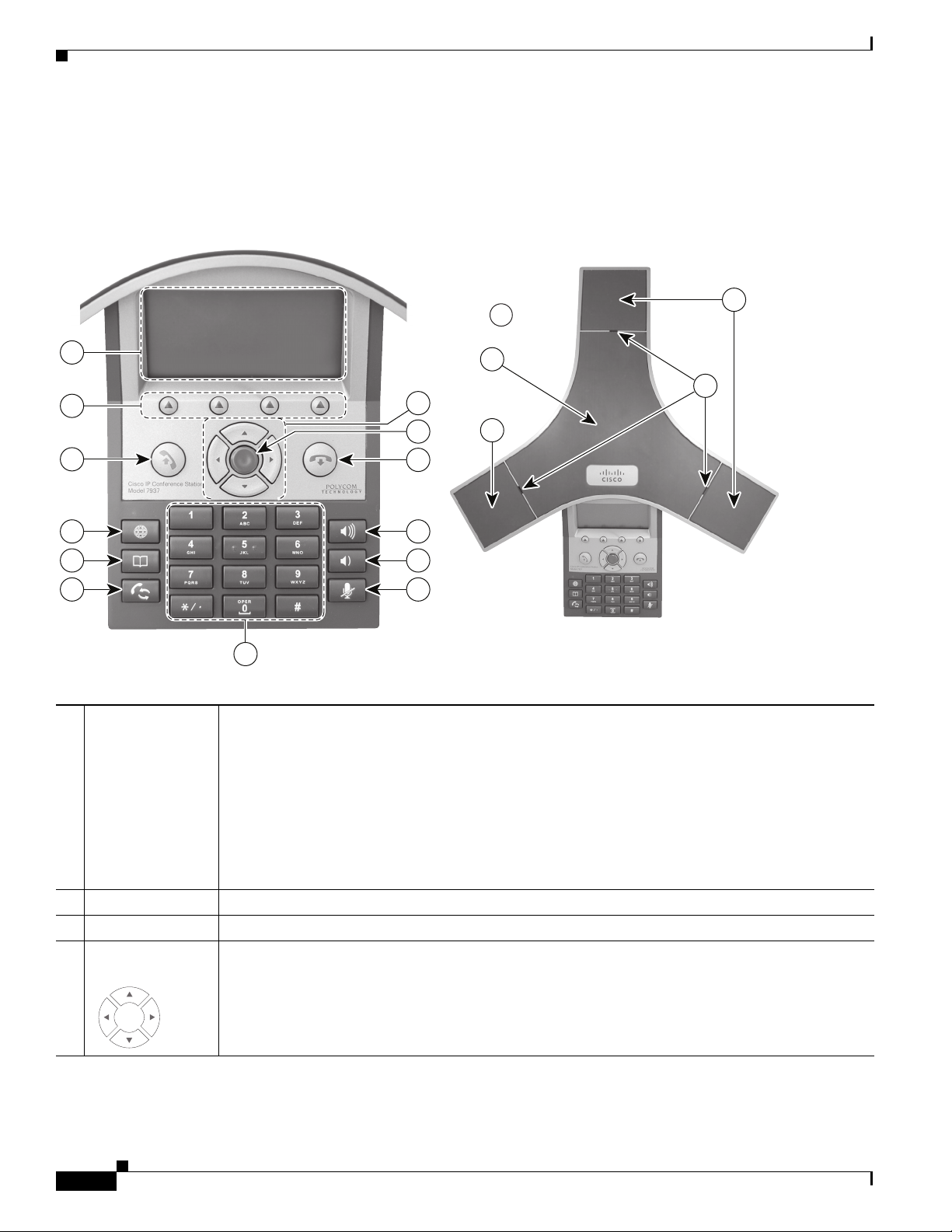
Figure 1-1 shows the main components of the conference station.
Figure 1-1 Cisco Unified IP Conference Station 7937G
Chapter 1 An Overview of the Conference Station
1
16
15
14
13
12
11
4
5
6
7
8
9
3
2
10
1 LED indicators Three multi-color LED indicators provide call status information:
• Off: Ready, Call State Off
• Solid amber: Powering On
• Solid red: Powering On, Mute, or Voice Message
2
1
185261
• Flashing red: Hold
• Solid green: Dial Tone, Dialing, or Connected
• Flashing green: Incoming Call (Ringing/Connecting), or Receiving
2 Microphones Three internal unidirectional microphones.
3 Speaker Internal speaker.
4 Navigation buttons
Allow you to scroll through menus and highlight items.
(four)
Cisco Unified IP Conference Station 7937G Administration Guide for Cisco Unified Communications Manager 6.0
1-2
OL-11560-01 Rev. B0
Page 15
Chapter 1 An Overview of the Conference Station
Understanding the Conference Station
5 Select button Activates the currently highlighted screen menu option.
6 On-hook button Ends your current call.
7 Volume Up button Raises the volume of the speaker (off-hook) and the volume of the ringer (on-hook).
8 Volume Down
bu
tton
Lowers the volume of the speaker (off-hook) and the volume of the ringer (on-hook).
9 Mute button Toggles the Mute feature.
10 Keypad Allows you to dial conference statio
n conference station numbers, enter letters, and choose menu
items.
11 Redial button Dials the most recent number you called.
12 Directories button Toggles the Directories menu. Allows you to access ca
13 Applications
bu
tton
Toggles the Applications menu. Allows you to access the Messages, Settings, and Services menus.
ll logs, speed dials, and directories.
14 Off-hook button Obtains a dial tone to initiate a call, or answers an incoming call.
15 Softkey buttons
(four)
16 Conference station
sc
reen
OL-11560-01 Rev. B0
Allow you to select softkey options displayed on the screen.
Displays conference station menus and features.
Cisco Unified IP Conference Station 7937G Administration Guide for Cisco Unified Communications Manager 6.0
1-3
Page 16

What Networking Protocols Are Used?
What Networking Protocols Are Used?
The conference station supports several industry-standard and Cisco networking protocols required for
voice communication. Table 1-1 provides an overview of the networking protocols that the
conference station supports.
Ta b l e 1-1 Supported Networking Protocols on the Conference Station
Networking Protocol Purpose Usage Notes
Cisco Discovery
tocol (CDP)
Pro
Dynamic Host
onfiguration Protocol
C
(DHCP)
CDP is a device-discovery protocol
that runs on all Cisco-manufactured
equipment.
Using CDP, a device can advertise its
e
xistence to other devices and receive
information about other devices in
the network.
DHCP dynamically allocates and
assigns an IP address to network
devices.
The conference station uses CDP to communicate
nformation such as auxiliary VLAN ID, per port power
i
management details, and Quality of Service (QoS)
configuration information with the Cisco Catalyst switch.
DHCP is enabled by default. If disabled, you must manually
onfigure the IP address, subnet mask, gateway, and a TFTP
c
server on each conference station locally.
Chapter 1 An Overview of the Conference Station
DHCP enables you to connect a
conference station into the
and have the conference station
become operational without you
needing to manually assign an IP
address or to configure additional
network parameters.
Hypertext Transfer
Pro
tocol (HTTP)
Internet Protocol (IP) IP is a messaging protocol that
Real-Time Transport
tocol (RTP)
Pro
Skinny Client Control
Pro
tocol (SCCP)
HTTP is the standard way of
transferring information and moving
documents across the Internet and the
web.
addresses
the network.
RTP is a standard protocol for
transporting real-time data, such as
interactive voice and video, over data
networks.
SCCP includes a messaging set that
allows communications between call
control servers and endpoint clients
like IP conference stations. SCCP is
proprietary to Cisco Systems.
and sends packets across
network
Cisco recommends that you use DHCP custom option 150.
W
ith this method, you configure the TFTP server IP address
as the option value. For additional information about DCHP
configurations, refer to the “Cisco TFTP” chapter in
Unified Communications Manager System Guide.
Cisco
The conference stations uses HTTP for the XML services
and for troubleshooting purposes.
To communicate using IP, network devices must have an
assigned IP address, subnet, and gateway.
IP addresses, subnets, and gateways identifications are
utomatically assigned if you are using the conference
a
station with DHCP. If you are not using DHCP, you must
manually assign these properties to each conference station
locally.
The conference station uses the RTP protocol to
send/ receive real-time voice traffic from other conference
ns and gateways.
statio
The conference station uses SCCP for call control.
1-4
Cisco Unified IP Conference Station 7937G Administration Guide for Cisco Unified Communications Manager 6.0
OL-11560-01 Rev. B0
Page 17

Chapter 1 An Overview of the Conference Station
What Features are Supported on the Conference Station?
Table 1-1 Supported Networking Protocols on the Conference Station (continued)
Networking Protocol Purpose Usage Notes
Transmission Control
Pro
tocol (TCP)
Trivial File Transfer
Protocol
User Datagram Protocol
(UDP)
(TFTP)
TCP is a connection-oriented
transport protocol.
TFTP allows you to transfer files
over the network.
On the conference station, TFTP
enables y
file specific to the conference station
type.
UDP is a connectionless messaging
pro
Related Topics
• Understanding Interactions with Other Cisco Unified IP Communications Products, page 2-1
• Understanding the Conference Station Startup Process, page 2-5
• Network Configuration Menu, page 4-5
ou to obtain a configuration
tocol for delivery of data packets.
The conference station uses TCP to connect to
Cisco Unified Communications Manager and to access
XML se
TFTP requires a TFTP server in your network, which can be
au
a conference station to use a TFTP server other than the one
specified by the DHCP server, you must manually assign a
TFTP server from the Network Configuration menu on the
conference station.
The conference station transmits and receives RTP streams,
which utilize UDP.
rvices.
tomatically identified from the DHCP server. If you want
What Features are Supported on the Conference Station?
The conference station functions much like a digital business conference station, allowing you to place
and receive teleconference station calls. In addition to traditional telephony features, the conference
station includes features that enable you to administer and monitor the conference station as a network
device.
This section includes the following topics:
• Feature Overview, page 1-5
• Configuring Telephony Features, page 1-6
• Configuring Network Parameters Using the Conference Station, page 1-6
• Providing Users with Feature Information, page 1-7
Feature Overview
Conference stations provide traditional telephony functionality, such as call forwarding and transferring,
redialing, speed dialing, conference calling, and voice messaging system access. Conference stations
also provide a variety of other features. For an overview of the telephony features that the conference
station supports, see the
As with other network devices, you must configure c
Cisco Unified Communications Manager and the rest of the IP netw
settings to configure on a conference station, but if your network requires it, you can manually configure
an IP address, TFTP server, and subnet mask. For instructions on configuring the network settings on
the conference station, see
“Telephony Features Available for the
onference stations to prepare them to access
Chapter 4, “Configuring Settings on the Conference Station.”
Conference Station” section on page 5-1.
ork. By using DHCP, you have fewer
OL-11560-01 Rev. B0
Cisco Unified IP Conference Station 7937G Administration Guide for Cisco Unified Communications Manager 6.0
1-5
Page 18

What Features are Supported on the Conference Station?
The conference station can interact with other services and devices on your IP network to provide
enhanced functionality. For example, you can use XML to enable users to access information such as
weather, stocks, quote of the day, and other web-based information. For information about configuring
such services, see the
“Setting Up Services” section on page 5-8.
Finally, because the conference station is a network de
from it directly. This information can assist you with troubleshooting any problems users might
encounter when using their conference stations. See Chapter 7, “Viewing Model Informatio
Statistics on the Conference Station,” for more information.
Related Topics
• Chapter 4, “Configuring Settings on the Conference Station”
• Chapter 5, “Configuring Features, Templates, Services, and Users”
• Chapter 9, “Troubleshooting and Maintenance”
“Configuring Corporate and Personal Directories” section on page 5-6 and the
Configuring Telephony Features
Chapter 1 An Overview of the Conference Station
vice, you can obtain detailed status information
n, Status, and
You can modify certain settings for the conference station from Cisco Unified Communications
Manager Administration. Use this web-based application to set up conference station registration criteria
and calling search spaces, to configure corporate directories and services, and to modify
conference
Conference Station” section on page 5-1 and Ci
Administration Guide for addit
For more information about Cisco Unified Commun
Cisco Unified Communications Manager documentation, including Cisco Un
Manager System Guide. You can also use the context-sensitive help available within the application for
guidance.
You can access the complete Cisco Unified Communications Manager documentation suite at these
UR
LS:
http://www.cisco.com/en/US/products/sw/voicesw/ps556/tsd_products_support_series_home.html
http://www.cisco.com/en/US/products/ps7273/
Related Topic
• Telephony Features Available for the Conference Station, page 5-1
station button templates, among other tasks. See the “Telephony Features Available for the
sco Unified Communications Manager
ional information.
ications Manager Administration, refer to
ified Communications
tsd_products_support_series_home.html
Configuring Network Parameters Using the Conference Station
You can configure parameters such as DHCP, TFTP, and IP settings on the conference station itself. You
can also obtain statistics about a current call or firmware versions on the conference station.
1-6
For more information about configuring features and viewing statistics from the conference station, see
Chapter 4, “Configuring Settings on the C
Information, Status, and Statistics on the Conference Station.”
Cisco Unified IP Conference Station 7937G Administration Guide for Cisco Unified Communications Manager 6.0
onference Station,” and Chapter 7, “Viewing Model
OL-11560-01 Rev. B0
Page 19

Chapter 1 An Overview of the Conference Station
Providing Users with Feature Information
If you are a system administrator, you are likely the primary source of information for conference station
users in your network or company. To ensure that you distribute the most current feature and procedural
information, familiarize yourself with conference station documentation. Make sure to visit the
Unified IP Conference Station web site:
Cisco
Understanding Security Features for Conference Stations
http://www.cisco.com/en/US/products/hw/phones/ps3
From this site, you can access various user guides.
In addition to providing users with documentation, it is important to inform them about available
ference station features—including features specific to your company or network—and about how to
con
access and customize those features, if appropriate.
For a summary of some of the key information tha
administrators to provide, see Appendix A, “Providing Information to Users Via a Website.”
79/tsd_products_support_series_home.html
t conference station users need their system
Understanding Security Features for Conference Stations
Implementing security in the Cisco Unified Communications Manager system prevents identity theft of
the conference station and Cisco Unified Communications Manager server and p
Table 1-2
Ta b l e 1-2 Conference Station and Cisco Unified Communications Manager
Topic Reference
Detailed explanation of security, including set up,
conf
for Cisco Unified Communications Manager and
conference stations
Security features supported on the
station
Viewing a security profile name See the “U
Security and the conference st
Security and conference station configuration files See the “U
Changing the TFTP Server 1 or TFTP Server 2
op
implemented
Understanding security icons in the
Ca
e CallManager Configuration menu on the
th
conference station
Items on the Security Configuration menu on the
conference station
shows where you can find additional information about security in this and other documents.
Security Topics
Refer to Cisco Unified Communications Manager
iguration, and troubleshooting information
conference
ation startup process See the “Understanding the Conference Station
tion on the conference station when security is
llManager 1 through CallManager 5 options in
Security Guide
See the “Overview of Supported Security
Features” section on page 1-8
nderstanding Security Profiles” section
on page 1-9
Startup Process” section on page 2-5
nderstanding Conference Station
Configuration Files” section on page 2-4
See Table 4-3 on page 4-5
See the “
section on page 4-9
See the “Se
page 4-11 and the “Security Configuration Menu”
section on page 4-12
CallManager Configuration Menu”
curity Configuration Menu” section on
revents data tampering.
OL-11560-01 Rev. B0
Cisco Unified IP Conference Station 7937G Administration Guide for Cisco Unified Communications Manager 6.0
1-7
Page 20

Understanding Security Features for Conference Stations
Chapter 1 An Overview of the Conference Station
Table 1-2 Conference Station and Cisco Unified Communications Manager
Security Topics (continued)
Topic Reference
Disabling access to a conference station’s web
pages
Troubleshooting Refer to Cisco Uni
Resetting or restoring the conference station See the “R
Overview of Supported Security Features
Table 1-3 provides an overview of the security features that the conference station supports. For more
information about these features and about Cisco Unified Communications Manager and conference
station s
For information about current security settings on a conference
menus on the conference station (choose Applications > Settings > Security Configuration and choose
Applications > Settings > Device Configuration > Security Configuration). For more information,
see
ecurity, refer to Cisco Unified Communications Manager Security Guide.
Chapter 4, “Configuring Settings on the Conference Station.”
See the “D
isabling and Enabling Web Page
Access” section on page 8-2
fied Communications Manager
Security Guide, “Troubleshooting chapter”
esetting or Restoring the Conference
Station” section on page 9-11
station, look at the security configuration
Ta b l e 1-3 Overview of Security Features
Feature Description
Security profiles Always defines the conference station as nonsecure. See
Understanding Security Profiles, page 1-9 for more information.
802.1X Authentication for
conference stations
Optional disabling of the web
ser
ver functionality for a
The conference station can
gain access to the network.
You can prevent access to a conference station’s web page which
displays a variety of operational statistics for the conference station.
use 802.1X authentication to request and
conference station
Conference station hardening Additional security options, which you control from
Ci
sco Unified Communications Manager Administration:
• Disabling Gratuitous ARP (GARP).
• Disabling or restricting access to the Settings menu. If you
restrict access, users can only access the User Preferences menu
from the Settings menu.
• Disabling access to web pages for a conference station.
• Disabling SSH access to the conference station.
Related Topics
• Understanding Security Profiles, page 1-9
• Device Configuration Menu, page 4-8
1-8
Cisco Unified IP Conference Station 7937G Administration Guide for Cisco Unified Communications Manager 6.0
OL-11560-01 Rev. B0
Page 21

Chapter 1 An Overview of the Conference Station
Overview of Configuring and Installing Conference Stations
Understanding Security Profiles
All conference stations that support Cisco Unified Communications Manager use a security profile
which defines the conference station as nonsecure. For information about the security profile, refer to
Cisco Unified Communications Manager Security Guide, Release 6.0.
Overview of Configuring and Installing Conference Stations
When deploying a new IP telephony system, system administrators and network administrators must
complete several initial configuration tasks to prepare the network for IP telephony service. For
nformation and a checklist for setting up and configuring a complete Cisco IP telephony network, refer
i
to the “System Configuration Overview” chapter in Cisco Unified Communications Manager
Guide.
System
After you have set up the IP telephony system and conf
Communications Manager, you can add conference stations to the system.
The following topics provide an overview of procedures for adding conference stations to your network:
igured system-wide features in Cisco Unified
• Configuring Conference Stations in Cisco Unified Communications Manager, page 1-9
• Installing Conference Stations, page 1-12
Configuring Conference Stations in Cisco Unified Communications Manager
To add conference stations to the Cisco Unified Communications Manager database, you can use:
• Auto-registration
• Cisco Unified Communications Manager Administration
• Bulk Administration Tool (BAT)
• BAT and the Tool for Auto-Registered Phones Support (TAPS)
For more information about these c
Communications Manager Database” sectio
For general information about configuring conference stations in Cisco Unified Communications
nager, refer to the “Cisco Unified IP Phones” chapter in Cisco U
Ma
System Guide.
hoices, see the “Adding Conference Stations to the Cisco Unified
n on page 2-7.
nified Communications Manager
OL-11560-01 Rev. B0
Cisco Unified IP Conference Station 7937G Administration Guide for Cisco Unified Communications Manager 6.0
1-9
Page 22

Chapter 1 An Overview of the Conference Station
Overview of Configuring and Installing Conference Stations
Checklist for Configuring the Conference Station in Cisco Unified Communications Manager
Table 1-4 provides an overview and checklist of configuration tasks for the conference station in
Cisco Unified Communications Manager Administration. The list presents a suggested order to guide
ou through the conference station configuration process. Some tasks are optional, depending on your
y
system and user needs. For detailed information, refer to the list sources.
Ta b l e 1-4 Checklist for Configuring the Conference Station in Cisco Unified Communications Manager
Task Purpose For More Information
1. Gather the following information
about the conference station:
• Conference station model
• MAC address
• Physical location of the
conference station
• Name or user ID of conference
station user
• Device pool
Provides a list of configuration
irements for setting up
requ
conference stations.
Identifies preliminary configuration
th
at you need to perform before
configuring individual conference
stations, such as conference station
key button templates or softkey
templates.
Refer to Cisco Unif
Manager System Guide, “Cisco Unified IP
Phones” chapter.
See the “T
elephony Features Available for
the Conference Station” section on page 5-1.
ied Communications
• Partition, calling search space,
and location information
• Directory number assigned to
the conference station
• Cisco Unified Communications
Manager user to associate with
conference station
• Conference station usage
information that affects
conference station templates
(button and softkey), features,
services, or conference station
applications
2. Customize button templates (if
required).
3. Add and configure the conference
station.
Allows you to create a custom
button template with the Privacy
feature. You can assign this
template to shared conference
stations so users have access to the
Privacy feature.
Adds the device with its default
settings to Cisco Unified
Commu
nications Manager.
Refer to Cisco Unified Communications
Manager Administration Guide, “Phone
Button Template Configuration” chapter.
See the “M
odifying Button Templates”
section on page 5-7.
Refer to Cisco Unified Communications
Man
ager Administration Guide, “Cisco
Unified IP Phone Configuration” chapter.
For information about Product Specific
Conf
iguration fields, refer to the Help in the
Phone Configuration window.
1-10
Cisco Unified IP Conference Station 7937G Administration Guide for Cisco Unified Communications Manager 6.0
OL-11560-01 Rev. B0
Page 23

Chapter 1 An Overview of the Conference Station
Overview of Configuring and Installing Conference Stations
Table 1-4 Checklist for Configuring the Conference Station in Cisco Unified Communications Manager (continued)
Task Purpose For More Information
4. Add and configure the directory
number on the conference station.
Adds the directory number and
features associated with the
directory number to the conference
station.
Refer to Cisco Unified Communications
Manager Administration Guide, “Cisco
Unified IP Phone Configuration” chapter,
“Directory Number Configuration” and
“Creating a Cisco Unity Voice Mailbox”
sections.
5. Customize softkey templates. Adds, deletes, or changes order of
softkey features that display on the
user’s conference station to meet
feature usage needs.
6. Assign speed-dial numbers
(optional).
Adds speed-dial numbers.
Note Users can change speed-dial
settings on their conference
stations by using the
Options web pages.
User
7. Configure conference station
services and assign services
(optional).
Provides conference station
services.
Note Users can add or change
services on their conference
stations by using the
Options web pages.
User
8. Add user information. Adds user information to the global
directory for Cisco Unified
Communications Manager.
See the “T
elephony Features Available for
the Conference Station” section on page 5-1.
Refer to Cisco Unified Communications
Manager Administration Guide, “Softkey
Template Configuration” chapter.
See the “C
onfiguring Softkey Templates”
section on page 5-8.
Refer to:
• Cisco Unified Communications Manager
Administration Guide,
“Cisco Unified IP Phone Configuration”
r.
chapte
• Cisco Unified Communications Manager
System Guide, “Cisco Unified IP
Phones” chapter.
Refer to Cisco Unified Communications
Man
ager Administration Guide, “Cisco
Unified IP Phone Services Configuration”
r.
chapte
See the “Setting Up Service
s” section on
page 5-8.
Refer to Cisco Unified Communications
Manager Administration Guide, “Adding a
New User” chapter.
9. Associate a user and a user group
with a conference station.
Cisco Unified IP Conference Station 7937G Administration Guide for Cisco Unified Communications Manager 6.0
OL-11560-01 Rev. B0
Provides users with control over
their conference station such as
forwarding calls or adding
speed-dial numbers or services.
Note Some conference stations,
such as those in conference
rooms, do not have an
associated user.
See the “
Adding Users to Cisco Unified
Communications Manager” section on
page 5-9.
Refer to Cisco Unified Communications
ager Administration Guide, “Adding a
Man
New User” chapter, “Associating Devices to
a User” section.
1-11
Page 24

Overview of Configuring and Installing Conference Stations
Installing Conference Stations
After you have added the conference stations to the Cisco Unified Communications Manager database,
you can complete the conference station installation. You (or the conference station users) can install the
conference station at the users’s location. The Cisco Unified IP Conference Station 7937G Installation
ide provides directions for connecting the conference station to the network, and connecting any
Gu
optional accessories to the conference station. You can access the guide at the following URL:
Chapter 1 An Overview of the Conference Station
http://www.cisco.com/en/US/products/hw/phones/ps3
After the conference station is connected to the ne
and the conference station registers with Cisco Unified Communications Manager. To finish installing
onference station, configure the network settings on the conference station depending on whether
the c
you enable or disable DHCP service.
If you used auto-registration, you need to update the specific configuration information for the
confere
directory number.
nce station such as associating the conference station with a user, changing the button table, or
Checklist for Installing the Conference Station
Table 1-5 provides an overview and checklist of installation tasks for the conference station. The list
presents a suggested order to guide you through the con
optional, depending on your system and user needs. For detailed procedures and information, refer to
the sources in the list.
Ta b l e 1-5 Checklist for Installing the Cisco Unified IP Conference Station 7937G
Task Purpose For More Information
1. Choose the power source for the
conference station:
• Power over Ethernet (PoE)
79/tsd_products_support_series_home.html
twork, the conference station startup process begins
ference station installation. Some tasks are
Determines how the
onference station receives
c
power.
See Providing Power to
the Conference Station,
page 2-2.
1-12
• External power supply
2. Assemble the conference station,
adjust conference station placement,
and connect the network cable.
3. Monitor the conference station
startup process.
Cisco Unified IP Conference Station 7937G Administration Guide for Cisco Unified Communications Manager 6.0
Locates and installs the
conference station in the
network.
Verifies that the conference
station is configured properly.
See Installing the
Conference Station,
page 3-4.
See Verifying the
Conference Station
Startup Process, page 3-8.
OL-11560-01 Rev. B0
Page 25

Chapter 1 An Overview of the Conference Station
Table 1-5 Checklist for Installing the Cisco Unified IP Conference Station 7937G (continued)
Task Purpose For More Information
4. Configure these network settings on
the conference station by choosing
Applications > Settings >
Network
Configuration.
To enable DHCP:
a. Set DHCP Enabled to Ye s.
b. To use an alternate TFTP server,
set Alternate TFTP to Ye s.
c. Enter an IP address for
TFTP Server 1.
To disa b l e DHCP :
a. Set DHCP Enabled to No.
b. Enter a static IP address for the
conference station.
c. Enter the Subnet Mask.
d. Enter the IP address for
Default Router 1.
Overview of Configuring and Installing Conference Stations
Using DHCP—The IP address
matically assigned and
is auto
the conference station is
directed to a TFTP Server.
Note Consult with the
network administrator
if you need to assign
an alternative TFTP
server instead of using
the TFTP server
assigned by DHCP.
Without DHCP—You must
onfigure the IP address,
c
TFTP server, subnet mask,
domain name, and default
router locally on the
conference station.
See the “Con
figuring
Startup Network Settings”
section on page 3-9.
See the “N
etwork
Configuration Menu”
section on page 4-5.
e. Enter the Domain Name where
the conference station resides.
f. Set Alternate TFTP to Ye s.
g. Enter an IP address for
TFTP Server 1.
5. Set up security on the conference
station.
6. Make calls with the conference
station.
7. Provide information to end users
about how to use their conference
stations and how to configure their
conference station options
.
Provides protection against
data tampering threats and
identity theft of conference
stations.
Verifies that the conference
station and features work
correctly.
Ensures that users have
ad
equate information to
successfully use their
conference stations.
See the “Security
Configuration Menu”
section on page 4-11.
See the “
Security
Configuration Menu”
section on page 4-12.
Refer to Cisco Unified
IP Conference Station
7G Phone Guide for
793
Cisco Unified
Communications
Manager 6.0.
See Appendix A,
“Providing Information to
Users Via a Website.”
OL-11560-01 Rev. B0
Cisco Unified IP Conference Station 7937G Administration Guide for Cisco Unified Communications Manager 6.0
1-13
Page 26

Overview of Configuring and Installing Conference Stations
Chapter 1 An Overview of the Conference Station
1-14
Cisco Unified IP Conference Station 7937G Administration Guide for Cisco Unified Communications Manager 6.0
OL-11560-01 Rev. B0
Page 27

CHAP T E R
2
Preparing to Install the Conference Station on
Your Network
The Cisco Unified IP Conference Station 7937G enables you to communicate using voice over a data
network. To provide this capability, the conference stations depend upon and interact with several other
key Cisco Internet Protocol (IP) Telephony and network components, including Cisco Unified
Commu
(DHCP) servers, Trivial File Transfer Protocol (TFTP) servers, media resources, and so on.
This chapter focuses on the interactions be
Communications Manager, DNS and DHCP servers, TFTP servers, and switches. It also describes
options for powering conference stations.
For related information about voice and IP communications, refer to this URL:
http://www.cisco.com/en/US/partner/products/sw/voicesw/index.html
This chapter provides an overview of the interaction betwee
components of a Voice over IP (VoIP) network. It covers these topics:
nications Manager 6.0, Domain Name System (DNS) and Dy
tween the conference station and Cisco Unified
n the conference station and other key
namic Host Configuration Protocol
• Understanding Interactions with Other Cisco Unified IP Communications Products, page 2-1
• Providing Power to the Conference Station, page 2-2
• Understanding Conference Station Configuration Files, page 2-4
• Understanding the Conference Station Startup Process, page 2-5
• Adding Conference Stations to the Cisco Unified Communications Manager Database, page 2-7
• Determining the MAC Address of a Conference Station, page 2-9
Understanding Interactions with Other Cisco Unified IP
Communications Products
To function in the IP telephony network, the conference station must be connected to a networking
device, such as a Cisco Catalyst switch. You must also register the conference station with a
Cisco Unified Communications Manager system before sending and receiving calls.
This section includes the following topic:
• Understanding How the Conference Station Interacts with Cisco Unified Communications Manager,
page 2-2
OL-11560-01 Rev. B0
Cisco Unified IP Conference Station 7937 Administration Guide for Cisco Unified Communications Manager 6.0
2-1
Page 28

Chapter 2 Preparing to Install the Conference Station on Your Network
Providing Power to the Conference Station
Understanding How the Conference Station Interacts with Cisco Unified
Communications Manager
Cisco Unified Communications Manager is an open and industry-standard call processing system.
Cisco Unified Communications Manager software sets up and tears down calls between
confere
corporate IP network. Cisco Unified Communications Manager manages the components of the IP
te
features as call conferencing and route planning. Cisco Unified Communications Manager also provides:
• Firmware for conference stations
• Authentication and encryption (if configured for the telephony system)
• Configuration file
• Conference station registration
• Call preservation, so that a media session continues if signaling is lost between the primary
For information about configuring Cisco Unified Communications Manager to work with the IP devices
described in thi
Cisco Unified Communications Manager System Guide, and to Ci
Security Guide.
For an overview of security functionality for the
Features for Conference Stations” section on page 1-7.
nce stations, integrating traditional pri
lephony system—the conference stations, the access gateways, and the resources necessary for such
Cisco Unified Communications Manager and a conference station
s chapter, refer to Cisco Unified Communications Manager Administration Guide,
vate branch exchange (PBX) functionality with the
sco Unified Communications Manager
conference station, see the “Understanding Security
Note If the conference station model that you want to configure does not appear in the Phone Type drop-down
list in Cisco Unified Communications Manager Administration, go to the following URL and install the
atest support patch for your version of Cisco Unified Communications Manager:
l
http://www.cisco.com/kobayashi/sw-center/sw-voice.shtml
Related Topic
• Telephony Features Available for the Conference Station, page 5-1
Providing Power to the Conference Station
The conference station can be powered with external power or with Power over Ethernet (PoE). External
power is provided through a separate power supply. PoE is provided by a switch through the Ethernet
cable attached to a conference station.
Note When you install a conference station that is powered by an optional external power supply, do the
following:
• Use a power interface cable to attach to the PoE cable and LAN wall port. See the “Installing the
Conference Station” section on page 3-4 for instructions on how to atta
• Connect the power supply to the conference station and to a power outlet before you connect the
Ethernet cable to the conference station. When you remove a conference station that is powered with
external power, disconnect the Ethernet cable from the conference station before you disconnect the
power supply.
ch the power interface cable.
2-2
Cisco Unified IP Conference Station 7937 Administration Guide for Cisco Unified Communications Manager 6.0
OL-11560-01 Rev. B0
Page 29

Chapter 2 Preparing to Install the Conference Station on Your Network
These sections provide more information about powering a conference station:
• Power Guidelines, page 2-3
• Conference Station Power Consumption and Display Brightness, page 2-3
• Power Outage, page 2-4
• Obtaining Additional Information about Power, page 2-4
Power Guidelines
Table 2-1 provides guidelines that apply to external power and to PoE power for conference stations.
Ta b l e 2-1 Guidelines for Powering the Conference Station
Power Type Guidelines
External power—Provided by
xternal power supply
an e
PoE power—Provided by a
itch through the Ethernet
sw
cable attached to the conference
station
• The conference station is rated 48 V DC, 0.375 A. When you use the conference station
with an optional external power supply, the power supply must be a listed power supply
with a Limited Power Source (LPS) output that is rated 48 V, min 0.375 A.
• The inline power patch panel WS-PWR-PANEL is not compatible with the conference
station.
• To ensure uninterrupted operation of the conference station, make sure that the switch
has a backup power supply.
• Make sure that the CatOS or IOS version running on your switch supports your
intended conference station deployment. Refer to the documentation for your switch
for operating system version information.
Providing Power to the Conference Station
Conference Station Power Consumption and Display Brightness
The power consumed by a conference station depends on its power configuration. See Tabl e 2-1 for a
power configuration overview. See Tabl e 2-2 for the maximum power consumed b
for each configuration option and
Note Power consumption values shown in the table include power losses in the cable that connects the
conference station to the switch.
Ta b l e 2-2 Power Consumption and Display Brightness for Power Configurations
Power Configuration
IEEE 802.3af Class 3 power from a Cisco switch, without
bi
directional power negotiation
IEEE 802.3af Class 3 power fr
om a third-party switch 6.3 W Approx. 1/2
IEEE 802.3af Class 3 power from a Cisco switch, with
directional power negotiation enabled
bi
the correlating conference station screen brightness level.
Max. Power Consumed
f
rom a Switch
Conference Station Screen
Brightness
6.3 W Approx. 1/2
10.25 W Full
1
y a conference station
OL-11560-01 Rev. B0
Cisco Unified IP Conference Station 7937 Administration Guide for Cisco Unified Communications Manager 6.0
2-3
Page 30

Chapter 2 Preparing to Install the Conference Station on Your Network
Understanding Conference Station Configuration Files
Table 2-2 Power Consumption and Display Brightness for Power Configurations (continued)
Max. Power Consumed
Power Configuration
IEEE 802.3af Class 3 power from a Cisco switch (with or
wi
thout bidirectional power negotiation enabled) or from a
third-party switch
External power — Full
1. Starts at approximately 1/2 brightness, changes to full brightness when the conference station negotiates additional power.
from a Switch
15.4 W Near full
Conference Station Screen
Brightness
Power Outage
Your accessibility to emergency service through the conference station is dependent on the
conference station being powered. If there is an interruption in the power supply, Service and Emergency
ling Service dialing will not function until power is restored. In the case of a power failure or
Cal
disruption, you may need to reset or reconfigure equipment before using the Service or Emergency
Calling Service dialing.
Obtaining Additional Information about Power
For related information about power, refer to the documents shown in Tab le 2-3. These documents
provide information about these topics:
• Cisco switches that work with the conference station
• The Cisco IOS releases that support bidirectional power negotiation
• Other requirements and restrictions regarding power
Ta b l e 2-3 Related Documentation for Power
Document Topics URL
PoE Solutions http://www.cisco.com/en/US/netsol/ns340/ns394/ns147/ns412/
networking_solutions_package.html
Cisco Catalyst Switches http://www.cisco.com/univercd/cc/td/doc/product/lan/index.htm
Integrated Service Routers http://www.cisco.com/en/US/products/hw/routers/index.html
Cisco IOS Software http://www.cisco.com/en/US/products/sw/iosswrel/
products_ios_cisco_ios_software_category_home.html
Understanding Conference Station Configuration Files
Configuration files for a conference station are stored on the TFTP server and define parameters for
connecting to Cisco Unified Communications Manager. In general, an
Cisco Unified Communications Manager that requires the conferenc
made to the conference station’s configuration file automatically.
Configuration files also contain information about which image load the conference station should be
nning. If this image load differs from the one currently loaded on a conference station, the conference
ru
station contacts the TFTP server to request the required load files.
y time you make a change in
e station to be reset, a change is
2-4
Cisco Unified IP Conference Station 7937 Administration Guide for Cisco Unified Communications Manager 6.0
OL-11560-01 Rev. B0
Page 31

Chapter 2 Preparing to Install the Conference Station on Your Network
A conference station accesses a default configuration file named XmlDefault.cnf.xml from the TFTP
server when these conditions exist:
• You have enabled auto-registration in Cisco Unified Communications Manager
• The conference station has not been added to the Cisco Unified Communications Manager Database
• The conference station is registering for the first time
If auto registration is not enabled and the conference station has not been added to the
Cisco Unified Communications Manager Database, the conferen
rejected. In this case, the conference station will reset and attempt to register repeatedly.
Understanding the Conference Station Startup Process
ce station registration request will be
If the conference station has registered before, the conf
erence station will access the configuration file
named SEPmac_address.cnf.xml, where mac_address is the Media Access Control (MAC) address of
the conference station.
Understanding the Conference Station Startup Process
When connecting to the VoIP network, the conference station goes through a standard startup process,
as described in Table 2-4. Depending on your specific network configuration, not all of these process
steps may occur on your conference station.
Ta b l e 2-4 Conference Station Startup Process
Process Step Description Related Topics
1. Obtaining power
from the switch
2. Loading the stored
conference station
image
3. Configuring VLAN If the conference station is connected to a
4. Obtaining an IP
address
If a conference station is not using external power,
the switch provides in-line power through the
Ethernet cable attached to the conference station.
The conference station has non-volatile Flash
memory in which it stores firmware images and
user-defined preferences. At startup, the
conference station runs a bootstrap loader that
loads a conference station image stored in Flash
memory. Using this image, the conference station
initializes its software and hardware.
Cisco switch, the switch next informs the
conference station of
the voice VLAN defined on
the switch port. The conference station needs to
know its VLAN membership before it can proceed
with the DHCP request for an IP address.
If the conference station is using DHCP to obtain
an IP address, the conference station queries the
DHCP server to obtain one. If you are not using
DHCP in your network, you must assign static IP
addresses to each conference station locally.
See the “Providing Power to the Conference
Station” section on page 2-2.
See the “
Resolving Startup Problems” section
on page 9-2.
See the “Resolving Startup Problems” section
on page 9-2.
See the “Net
work Configuration Menu”
section on page 4-5.
See the “
Resolving Startup Problems” section
on page 9-2.
See the “Network Configuration Menu”
section on page 4-5.
See the “
Resolving Startup Problems” section
on page 9-2.
OL-11560-01 Rev. B0
Cisco Unified IP Conference Station 7937 Administration Guide for Cisco Unified Communications Manager 6.0
2-5
Page 32

Chapter 2 Preparing to Install the Conference Station on Your Network
Understanding the Conference Station Startup Process
Table 2-4 Conference Station Startup Process (continued)
Process Step Description Related Topics
5. Accessing a TFTP
server
In addition to assigning an IP address, the DHCP
server directs the conference station to a TFTP
Server. If the conference station has a
statically-defined IP address, you must configure
the TFTP server locally on the conference station;
See the “Net
section on page 4-5.
See the “
Resolving Startup Problems” section
on page 9-2.
the conference station then contacts the TFTP
server directly.
Note You can also assign an alternative TFTP
server to use instead of the one assigned by
DHCP.
6. Requesting the
configuration file
7. Contacting
Cisco Unified
ommunications
C
Manager
The TFTP server has configuration files, which
define parameters for connecting to
Cisco Unified Communications Manager and
her information for the conference station.
ot
The configuration file defines how the conference
statio
n communicates with
Cisco Unified Communications Manager and
vides a conference station with its load ID.
pro
See the “U
nderstanding Conference Station
Configuration Files” section on page 2-4.
See the “
Resolving Startup Problems” section
on page 9-2.
See the “
Resolving Startup Problems” section
on page 9-2.
After obtaining the file from the TFTP server, the
conference station attempts to make a connection
to the highest priority Cisco Unified
Communications Manager on the list. The
conference station makes a non-secure TCP
connection.
If the conference station was manually added to
e database, Cisco Unified Communications
th
anager identifies the conference station. If the
M
conference station was not manually added to the
database and auto-registration is enabled in
Unified Communications Manager, the
Cisco
conference station atte
mpts to auto-register itself
in Cisco Unified Communications Manager.
Note Auto-registration is disabled when
security is enabled on Cisco Unified
ommunications Manager. In this case,
C
the conference station must be manually
added to the Cisco Unified
Communications Manager.
work Configuration Menu”
2-6
Cisco Unified IP Conference Station 7937 Administration Guide for Cisco Unified Communications Manager 6.0
OL-11560-01 Rev. B0
Page 33

Chapter 2 Preparing to Install the Conference Station on Your Network
Adding Conference Stations to the Cisco Unified Communications Manager Database
Adding Conference Stations to the Cisco Unified
Communications Manager Database
Before installing the conference station, you must choose a method for adding conference stations to
Cisco Unified Communications Manager. These secti
• Adding Conference Stations with Auto-Registration, page 2-7
• Adding Conference Stations with Auto-Registration and TAPS, page 2-8
• Adding Conference Stations with Cisco Unified Communications Manager Administration,
page 2-9
• Adding Conference Stations with BAT, page 2-9
Table 2-5
Cisco Unified Communications Manager.
Ta b l e 2-5 Methods for Adding Conference Stations to the Cisco Unified Communications
Method
Auto-registration No Provides no control over directory number assignment to
Auto-registration
wi
Auto-Registered
Phones Support
(TAPS)
Using
Ci
sco Unified
ommunications
C
Manager
Administration
Using BAT Ye s Can add groups of same model of conference station.
provides an overview of these methods for adding conference stations to
Manager Database
Requires MAC
Address? Notes
conference stations.
No Requires auto-registration and the Bulk Administration Tool
th the Tool for
Yes Must add conference stations individually.
(BAT); updates the Cisco Unified Communications Manager
database wit
user calls TAPS from the conference station.
Can schedule when conference stations are added to
sco Unified Communications Manager.
Ci
ons describe the methods:
h the MAC address and DNs for the device when
Adding Conference Stations with Auto-Registration
By enabling auto-registration before you begin installing conference stations, you can:
• Automatically add a conference station to the Cisco Unified Communications Manager database
when you physically connect the conference station to your IP telephony network. During
auto-registration, Cisco Unified Communications Manager assigns the next available sequential
irectory number to the conference station.
d
• Add conference stations without first gathering MAC addresses from the conference stations.
• Quickly enter conference stations into the Cisco Unified Communications Manager database and
modify any settings, such as the directory numbers, from Cisco Unified Communications Manager.
• Move auto-registered conference stations to new locations and assign them to different device pools
without affecting their directory numbers.
Cisco Unified IP Conference Station 7937 Administration Guide for Cisco Unified Communications Manager 6.0
OL-11560-01 Rev. B0
2-7
Page 34

Chapter 2 Preparing to Install the Conference Station on Your Network
Adding Conference Stations to the Cisco Unified Communications Manager Database
Note You should use auto-registration to add less than 100 conference stations to your network. To add more
than 100 conference stations to your network, use BAT. See the “Adding Conference Stations with BAT”
section on page 2-9.
In some cases, you might not want to use auto-registration: for example, if you want to assign a specific
di
rectory number to the conference station or if you plan to implement authentication or encryption, as
described in Cisco Unified Communications Manager Security Guide.
For information about enabling auto-registration, refer to “Enabling Auto-Registration” in the
Cisco Unified Communications Manager Administration Guide.
Related Topics
• Adding Conference Stations with Auto-Registration and TAPS, page 2-8
• Adding Conference Stations with Cisco Unified Communications Manager Administration,
page 2-9
• Adding Conference Stations with BAT, page 2-9
Adding Conference Stations with Auto-Registration and TAPS
You can add conference stations with auto-registration and TAPS without first gathering MAC addresses
from conference stations.
TAPS works with BAT to update a batch of confere
Cisco Unified Communications Manager database with dummy MA
update MAC addresses and download pre-defined configurations for conference stations.
Note Cisco recommends you use auto-registration and TAPS to add less than 100 conference stations to your
network. To add more than 100 conference stations to your network, use the Bulk Administration Tool
(BAT). See the “Adding Conference Stations with BAT” section on page 2-9.
To implement TAPS, you or the end-user dial a
the process is complete, the conference station will have downloaded its directory number and other
settings, and the conference station will be updated in Cisco Unified Communications Manager
istration with the correct MAC address.
Admin
Auto-registration must be enabled in Cisco Unified Communications Manager Administration for TAPS
o function.
t
Refer to Cisco U
nified Communications Manager Bulk Administration Guide for detailed instructions
about BAT and TAPS.
Related Topics
• Adding Conference Stations with Auto-Registration, page 2-7
• Adding Conference Stations with Cisco Unified Communications Manager Administration,
page 2-9
nce stations that were already added to the
C addresses. You use TAPS to
TAPS directory number and follow voice prompts. When
2-8
• Adding Conference Stations with BAT, page 2-9
Cisco Unified IP Conference Station 7937 Administration Guide for Cisco Unified Communications Manager 6.0
OL-11560-01 Rev. B0
Page 35

Chapter 2 Preparing to Install the Conference Station on Your Network
Determining the MAC Address of a Conference Station
Adding Conference Stations with Cisco Unified Communications Manager
Administration
You can add conference stations individually to the Cisco Unified Communications Manager database
using Cisco Unified Communications Manager Administration. To do so, you first need to obtain the
C address for each conference station.
MA
For information about determining a MAC address, see the “D
Conference Station” section on page 2-9.
After you collect MAC addresses, in Cisco Unified Communications Manager Administration, choose
vice > Phone, and then click Add New to begin.
De
For complete instructions and conceptual information about Cisco Unified Communications Manager,
o Cisco Unified Communications Manager Administration Guide and to Cisco Unif
refer t
Communications Manager System Guide.
Related Topics
• Adding Conference Stations with Auto-Registration, page 2-7
• Adding Conference Stations with Auto-Registration and TAPS, page 2-8
etermining the MAC Address of a
ied
• Adding Conference Stations with BAT, page 2-9
Adding Conference Stations with BAT
The Cisco BAT enables you to perform batch operations, including registration, on multiple
conference stations.
Before you can add conference stations using BAT only (not in conjunction with TAPS), you must obtain
AC address for each conference station.
the M
For information about determining a MAC address, see the “D
Conference Station” section on page 2-9.
For detailed instructions about using BAT, refer to Ci
Administration Guide and to Cisco Unified Communications Manager Bulk Administration Guide.
Related Topics
• Adding Conference Stations with Auto-Registration, page 2-7
• Adding Conference Stations with Auto-Registration and TAPS, page 2-8
• Adding Conference Stations with Cisco Unified Communications Manager Administration,
page 2-9
sco Unified Communications Manager
etermining the MAC Address of a
Determining the MAC Address of a Conference Station
OL-11560-01 Rev. B0
You can determine the MAC address for a conference station in any of these ways:
• From the conference station, choose Applications > Settings > Model Information and look at the
MAC Address field.
• Look at the MAC label on the back of the conference station.
• Display the conference station web page, and click the Device Information hyperlink.
For information about accessing the confere
for a Conference Station” section on page 8-2.
Cisco Unified IP Conference Station 7937 Administration Guide for Cisco Unified Communications Manager 6.0
nce station web page, see the “Ac c e ssin g t he Web P a g e
2-9
Page 36

Determining the MAC Address of a Conference Station
Chapter 2 Preparing to Install the Conference Station on Your Network
2-10
Cisco Unified IP Conference Station 7937 Administration Guide for Cisco Unified Communications Manager 6.0
OL-11560-01 Rev. B0
Page 37

CHAP T E R
3
Setting Up the Conference Station
This chapter includes the following topics, which help you install the Cisco Unified IP
Conference Station 7937G on an Internet Protocol (IP) telephony network:
• Before You Begin, page 3-1
• Understanding the Conference Station Components, page 3-3
• Installing the Conference Station, page 3-4
• Verifying the Conference Station Startup Process, page 3-8
• Configuring Startup Network Settings, page 3-9
Note Before you install a conference station, you must decide how to configure the conference station in your
network. Then you can install the conference station and verify its functionality. For more information,
see Chapter 2, “Preparing to Install the Conference Station on Your Network.”
Before You Begin
Before you install the conference station, review the requirements in these sections:
• Network Requirements, page 3-1
• Cisco Unified Communications Manager Configuration, page 3-2
• Safety, page 3-2
Network Requirements
For the conference station to successfully operate as a conference station endpoint in your network, your
network must meet these requirements:
• Working Voice over IP (VoIP) network:
–
VoIP configured on your Cisco routers and gateways
–
Cisco Unified Communications Manager Release 6.0 or later installed in your network and
configured to handle call processing
• IP network that supports Dynamic Host Configuration Protocol (DHCP) or manual assignment of
IP address, gateway, and subnet mask
OL-11560-01 Rev. B0
Cisco Unified IP Conference Station 7937G Administration Guide for Cisco Unified Communications Manager 6.0
3-1
Page 38

Before You Begin
Cisco Unified Communications Manager Configuration
The conference station requires Cisco Unified Communications Manager to handle call processing.
Refer to Cisco Unified Communications Manager Administration Guide or t
the Cisco Unified Communications Manager application to ensure that Cisco Unified Communications
ager is set up properly to manage the conference station and to properly route and process calls.
Man
If you plan to use auto-registration, verify that it is enabled and properly configured in
Cisco Unified Communications Manager before connecting any conference
information about enabling and configuring auto-registration, refer to Cisco Unified Communications
ager Administration Guide. Also, see the “Adding Conference Stations to the Cisco Unified
Man
Communications Manager Database” sectio
You must use Cisco Unified Communications Manager to configure and assig
conference stations. See the “Telephony Features Available for the Confe
page 5-1 for details.
In Cisco Unified Communications Manager, you can add users to the database and associate them with
ic conference stations. In this way, users gain access to web pages that allow them to configure
specif
items such as call forwarding, speed dialing, and voice messaging system options. See the
“Adding Users to Cisco Unified Communications Manager” section on page 5-9 for details.
n on page 2-7.
Chapter 3 Setting Up the Conference Station
o context-sensitive help in
station to the network. For
n telephony features to the
rence Station” section on
Safety
Warning
Warning
Warning
Warning
Warning
Review the following warnings before installing the conference station. To see translations of these
warnings, refer to the Regulatory Compliance and Safety Information for Cisco Unified IP
Conference Stations documen
Read the installation instructions before you connect the system to its power source.
Only trained and qualified personnel should be allowed to install, replace, or service this equipment.
Ultimate disposal of this product should be handled according to all national laws and regulations.
Do not work on the system or connect or disconnect cables during periods of lightning activity.
To avoid electric shock, do not connect safety extra low voltage (SELV) circuits to teleconference
station network voltage (TNV) circuits. LAN ports contain SELV circuits, and WAN ports contain TNV
circuits. Some LAN and WAN ports both use RJ-45 connectors. Use caution when connecting cables.
t that accompanied this device.
3-2
Caution Only use the proper Cisco approved external power supply. Reference the installation manual provided
with the conference station.
Cisco Unified IP Conference Station 7937G Administration Guide for Cisco Unified Communications Manager 6.0
OL-11560-01 Rev. B0
Page 39

Chapter 3 Setting Up the Conference Station
The following warnings apply when you use an external power supply.
Understanding the Conference Station Components
Warning
Warning
Warning
This product relies on the building's installation for short-circuit (overcurrent) protection. Ensure that
a fuse or circuit breaker no larger than 120 VAC, 15 A U.S. (240 VAC, 10 A international) is used on the
phase conductors (all current-carrying conductors).
The device is designed to work with TN power systems.
The plug-socket combination must be accessible at all times because it serves as the main
disconnecting device.
Understanding the Conference Station Components
The conference station includes these components:
• Network Ports
• Audio Auxiliary Port
Network Ports
The underside of the conference station includes these connector ports:
• Ethernet network port (RJ-45)—Labeled “LAN”
• Two external microphone ports (mini-VGA)—Labeled with stenciled microphone icons
Each type of port supports 10/100 Mbps half- or f
use either Category 3 or 5 cabling for 10-Mbps connections, but you must use Category 5 for 100 Mbps
connections.
Use the Ethernet network port to connect the conference station to the network. You must use a
str
aight-through cable on this port. The conference station can also obtain inline power from a switch
over this connection (Power over Ethernet). Figure 3-1 shows how to connect the conference station
the network using Power over Ethernet (PoE). If you use a
connect the conference station to the network, see Figure 3-2. For more information on powering the
conference station, see the “Providing Power to the Conference Station” section on page 2-2.
Use the external microphone ports to connect optional external microphones to the conference station.
Figure 3-3 shows how to connect the optional microphones to the conference station.
ull-duplex connections to external devices. You can
to
n external power source, rather than PoE, to
OL-11560-01 Rev. B0
Cisco Unified IP Conference Station 7937G Administration Guide for Cisco Unified Communications Manager 6.0
3-3
Page 40

Installing the Conference Station
Audio Auxiliary Port
The side of the conference station includes this port:
• Audio auxiliary port—Labeled with stenciled audio input/output symbol
The audio auxiliary port is on the right side of the c
audio serial port to facilitate full-duplex connections to an optional mobile conference station device.
You must use a straight-through cable on this port. Figure 3-4 shows how to connect the optional device
to the conference station.
Installing the Conference Station
You must connect the conference station to the network and a power source before using it. If you
choose, you can connect external microphones and a mobile conference station device to the conference
station. For a graphical representation of the connections, see the following figures:
• Figure 3-1—Shows the connections using Power over Ethernet (PoE) power.
• Figure 3-2—Shows the connections using an optional external power supply.
• Figure 3-3—Shows the connection of optional external microphones to the conference station.
Chapter 3 Setting Up the Conference Station
onference station under a flap you flip open. Use the
• Figure 3-4—Shows the connection of an optional mobile conference station device to the
conference station.
Figure 3-1 sho
Figure 3-1 Conference Station Cable Connections Using PoE
1
ws how to connect the conference station to the network using PoE.
3
2
185259
3-4
1 Connection of network cable to conference station RJ-45 port
2 Network cable (25-foot)
3 Connection of network cable to LAN port
Cisco Unified IP Conference Station 7937G Administration Guide for Cisco Unified Communications Manager 6.0
OL-11560-01 Rev. B0
Page 41

Chapter 3 Setting Up the Conference Station
Installing the Conference Station
To install a conference station using PoE, perform the following steps:
Procedure Notes Reference
1. Connect the end (without a ferrite bead) of a Category 5
straight-through Ethernet network cable to the LAN port on
the underside of a conference station.
2. Connect the other end (with a ferrite bead) of a Category 5
straight-through Ethernet network cable to a LAN port.
Each conference station ships
with one Ethernet cable in the
box.
See the “Network Ports”
section on page 3-3 for
guidelines.
See the “Network Ports”
section on page 3-3 for
guidelines.
Figure 3-2 sho
ws how to connect the conference station to the network if you use an optional external
power supply.
Figure 3-2 Conference Station Cable Connections Using Optional External Power Supply
4
3
5
2
6
1
7
8
1 Connection of network cable to conference station RJ-45 port
2 Network cable (25-foot)
3 Connection of network cable to the power interface cable
4 Power interface cable
5 Connection of power interface cable to LAN wall port
6 Connection of power interface cable to external power supply
7 External power supply
8 Connection of external power supply to wall outlet
Cisco Unified IP Conference Station 7937G Administration Guide for Cisco Unified Communications Manager 6.0
OL-11560-01 Rev. B0
185258
3-5
Page 42

Installing the Conference Station
To connect the conference station to the network using an optional external power source, perform the
following steps:
Procedure Notes Reference
1. Connect the external power
supply to the wall outlet.
The external power supply is an optional
item. It is not included with the
See the “Power Guidelines” section on
page 2-3.
conference station.
2. Connect the other end of the
external power supply to the
receptacle on the power
The power interface cable is an optional
item. It is not included with the
conference station.
interface cable.
3. Connect the power interface
cable to a network port.
4. Connect the other end of the
See the “Network Ports” section on page 3-3
for guidelines.
power interface cable to a
Category 5 straight-through
Ethernet network cable.
5. Connect the end (without a
ferrite bead) of a Category 5
Each conference station ships with one
Ethernet cable in the box.
See the “Network Ports” section on page 3-3
for guidelines.
straight-through Ethernet
network cable to the LAN
port on the underside of a
conference station.
Chapter 3 Setting Up the Conference Station
Figure 3-3 sh
ows how to connect the optional, external microphones to the back of the conference
station.
Figure 3-3 Connection of Optional External Microphones to Conference Station
185260
3-6
Cisco Unified IP Conference Station 7937G Administration Guide for Cisco Unified Communications Manager 6.0
OL-11560-01 Rev. B0
Page 43

Chapter 3 Setting Up the Conference Station
Figure 3-4 shows how to connect the optional mobile conference station device to the side of the
conference station.
Figure 3-4 Connection of Optional Mobile Conference Station Device to Conference Station
Installing the Conference Station
Related Topics
• Before You Begin, page 3-1
• Securing the Conference Station with a Cable Lock, page 3-7
• Configuring Startup Network Settings, page 3-9
Securing the Conference Station with a Cable Lock
You can secure the conference station to a desktop using a laptop cable lock. The lock connects to the
security slot on the side of the conference station, and the cable can be secured to a desktop.
The security slot can accommodate a lo
Kensington® laptop cable lock and laptop cable locks from other manufacturers that can fit into the
security slot.
ck up to 20 mm. Compatible laptop cable locks include the
185262
OL-11560-01 Rev. B0
Cisco Unified IP Conference Station 7937G Administration Guide for Cisco Unified Communications Manager 6.0
3-7
Page 44

Verifying the Conference Station Startup Process
Figure 3-5 shows how to connect a cable lock to the conference station.
Figure 3-5 Connecting a Cable Lock to the Conference Station
Chapter 3 Setting Up the Conference Station
Verifying the Conference Station Startup Process
After the conference station has power connected to it, the conference station begins its startup process
by cycling through these steps:
1. Ready, Call State Off: The LCD screen lights up and LED indicators on top of the console glow a
solid amber for 20 seconds.
2. Powering On: The LCD screen dims and the LED indicators turn a solid red and glow for an
additional five seconds.
Cisco Unified IP Conference Station 7937G Administration Guide for Cisco Unified Communications Manager 6.0
3-8
OL-11560-01 Rev. B0
Page 45

Chapter 3 Setting Up the Conference Station
3. Power On: The LCD screen lights up and displays the Cisco logo.
4. The main conference station LCD screen displays the following details:
–
Current date and time
–
Directory number
–
Softkeys
Configuring Startup Network Settings
If the conference station successfully passes throug
conference station does not start properly, see the “Resolving Startup Problems” section on page 9-2.
Configuring Startup Network Settings
If you are not using DHCP in your network, you must configure these network settings on the
conference station after installing the conference station on the netw
• IP address
• Subnet mask
• Default gateway IP address
• TFTP server IP address
You also may configure the domain name and the D
Collect this information and see the instructions in Ch
Station.”
Guidelines for Best Performance
Follow these guidelines to ensure optimum performance with the conference station and the external
microphones.
h these stages, it has started properly. If the
ork:
NS server settings, if necessary.
apter 4, “Configuring Settings on the Conference
Note See the “Conference Room Setup Examples” section on page 3-10 for an illustration of proper
OL-11560-01 Rev. B0
equipment placement for different conference room configurations.
• Use the conference station in closed offices and conference rooms up to 20 feet by 20 feet (without
external microphones) and 20 feet by 30 feet (with external microphones).
• Place the conference station base on a flat surface and make sure that it is clear from any reflective
surfaces.
• Maintain a minimum distance of four feet between each external microphone and the
conference station base and other objects.
• Make sure that all microphones are acoustically unobstructed.
• Position the external microphones toward the areas that need to be covered, and so that the main
pickup direction is pointed away from the conference station.
• Seat all conference participants the same distance from the conference station.
• Speak at normal conversation levels and direct your voice toward the conference station.
• Do not move or handle the conference station base or the external microphones while on a call, and
do not shuffle papers near the equipment.
• Minimize background noise from air conditioning units, fans, or other equipment in the office or
conference room.
Cisco Unified IP Conference Station 7937G Administration Guide for Cisco Unified Communications Manager 6.0
3-9
Page 46

Configuring Startup Network Settings
Conference Room Setup Examples
See Figure 3-6 for examples of proper placement of the conference station console and external
microphones in different conference
Figure 3-6 Cisco Unified IP Conference Station 7937G Base and External Microphone Placement
Chapter 3 Setting Up the Conference Station
room configurations.
3-10
Cisco Unified IP Conference Station 7937G Administration Guide for Cisco Unified Communications Manager 6.0
OL-11560-01 Rev. B0
Page 47

CHAP T E R
Configuring Settings on the Conference Station
The Cisco Unified IP Conference Station 7937G includes many configurable network, device, and
security settings that you may need to modify before the conference station is functional for your users.
You can access these settings, and change many of them, through menus on the conference station.
This chapter includes the following topics:
• Configuration Menus on the Conference Station, page 4-1
• Overview of Options Configurable from a Conference Station, page 4-4
• Network Configuration Menu, page 4-5
• Device Configuration Menu, page 4-8
• Security Configuration Menu, page 4-12
Configuration Menus on the Conference Station
4
The conference station includes the following configuration menus:
• Network Configuration menu—Provides options for viewing and making a variety of network
settings. For more information, see the “Network Configuration Menu” section on page 4-5.
• Device Configuration menu—Provides access to sub-menus from which you can view a variety of
non network-related settings. For more information, see the “Device Configuration Menu” section
on page 4-8.
• Security Configuration menu—Displays information about the current authentication security status
of the conference station. For more information, see the “Security Configuration M
page 4-12.
Before you can change option settings on the Netwo
unlock options for editing. See the “Unlocking and Locking Options” section on page 4-3 for
instructions.
For information about the keys you can use to edit
section on page 4-3.
You can control whether a conference station use
Settings Access field on the Phone Configuration page in Cisco Unified Communications Manager
istration. For more information, see the “Displaying a Configuration Menu” section on page 4-2,
Admin
or refer to Cisco Unified Communications Manager Administration Guide.
rk and Security Configuration menus, you must
or change option settings, see the “Editing Values”
r has access to conference station settings by using the
enu” section on
OL-11560-01 Rev. B0
Cisco Unified IP Conference Station 7937G Administration Guide for Cisco Unified Communications Manager 6.0
4-1
Page 48

Configuration Menus on the Conference Station
Related Topics
• Unlocking and Locking Options, page 4-3
• Editing Values, page 4-3
• Overview of Options Configurable from a Conference Station, page 4-4
• Network Configuration Menu, page 4-5
• Device Configuration Menu, page 4-8
• Security Configuration Menu, page 4-12
Displaying a Configuration Menu
To display a configuration menu, perform the following steps:
Note You can control whether a conference station has access to the Settings menu or to options on this menu
by using the Settings Access field in the Cisco Unified Communications Manager Administration Phone
iguration page. The Settings Access field accepts these values:
Conf
• Enabled—Allows access to the Settings menu.
• Disabled—Prevents access to the Settings menu.
Chapter 4 Configuring Settings on the Conference Station
• Restricted—Allows access to the User Preferences menu, but prevents access to other options on
the Settings menu.
If you cannot access an option on the Settings menu, chec
k the Settings Access field. For more
information, refer to the Cisco Unified Communications Manager Administration Guide.
Procedure
Step 1 Choose Applications > Settings.
Step 2 Perform one of these actions to select an item in the Settings menu:
• Use the Navigation button to select the desired item, and then press Select.
• Use the keypad on the conference station to enter the number that corresponds to the item.
Step 3 To exit a menu, press the Exit softkey.
Related Topics
• Unlocking and Locking Options, page 4-3
• Editing Values, page 4-3
• Overview of Options Configurable from a Conference Station, page 4-4
• Network Configuration Menu, page 4-5
• Device Configuration Menu, page 4-8
4-2
• Security Configuration Menu, page 4-12
Cisco Unified IP Conference Station 7937G Administration Guide for Cisco Unified Communications Manager 6.0
OL-11560-01 Rev. B0
Page 49

Chapter 4 Configuring Settings on the Conference Station
Unlocking and Locking Options
Configuration options that you can change from a conference station are locked by default to prevent
users from making changes that could affect the operation of a conference station. You must unlock these
options before you can change them.
Configuration Menus on the Conference Station
When options are inaccessibl
menus. When options are unlocked and accessible for modification, an un
e for modification, a locked padlock icon appears on the configuration
locked padlock icon
appears on these menus.
To unlock or lock options, press **
#. This action either locks or unlocks the options, depending on the
previous state.
Make sure to lock options after you have made your changes.
Caution Do not press **# to unlock options and then immediately press **# again to lock options. The
conference station will interpret this sequence as **#
**, which will reset the conference station. To lock
options after unlocking them, wait at least 10 seconds before you press **# again.
Related Topics
• Displaying a Configuration Menu, page 4-2
• Editing Values, page 4-3
• Overview of Options Configurable from a Conference Station, page 4-4
• Network Configuration Menu, page 4-5
• Device Configuration Menu, page 4-8
• Security Configuration Menu, page 4-12
Editing Values
Note The conference station provides several methods to reset or restore option settings, if necessary. For
When you edit the value of an option setting, follow these guidelines:
• Use the keys on the keypad to enter numbers and letters.
• To enter letters using the keypad, use a corresponding number key. Press the key one or more times
to display a particular letter. For example, press the 2 key once for “a,” twice quickly for “b,” and
three times quickly for “c.” After you pause, the cursor automatically advances to allow entry of the
next letter.
• To enter a period (for example, in an IP address), press the . (period) softkey or press * on the
keypad.
• Press << if you make a mistake. This softkey deletes the character to the left of the cursor.
• Press Cancel before pressing Save to discard any changes that you have made.
more information, see the “Resetting or Restoring the Conference Station” section on page 9-11.
OL-11560-01 Rev. B0
Cisco Unified IP Conference Station 7937G Administration Guide for Cisco Unified Communications Manager 6.0
4-3
Page 50

Chapter 4 Configuring Settings on the Conference Station
Overview of Options Configurable from a Conference Station
Related Topics
• Displaying a Configuration Menu, page 4-2
• Unlocking and Locking Options, page 4-3
• Overview of Options Configurable from a Conference Station, page 4-4
• Network Configuration Menu, page 4-5
• Device Configuration Menu, page 4-8
• Security Configuration Menu, page 4-12
Overview of Options Configurable from a Conference Station
The settings that you can change on a conference station fall into several categories, as shown in
Table 4-1 and Ta bl e 4-2. For a detailed explanation of each setting
see the “Network Configuration Menu” section on page 4-5 and the “Security Configuration Menu”
section on page 4-12.
and instructions for changing them,
Note There are certain options on the Network Configuration menu, Device Configuration menu, and
Security Configuration menu that are for display only or that you can configure from
Cisco Unified Communications Manager. These options are also described in the “Network
Configuration Menu” section on page 4-5, the “Device Configuration Menu” section on page 4-8, and
the “Security Configuration Menu” section on page 4-12.
Ta b l e 4-1 Network Settings Configurable from the Conference Station
Category Description Network Configuration Menu Option
DHCP settings Dynamic Host Configuration Protocol (DHCP)
automa
tically assigns IP addresses to devices when you
DHCP Enabled
connect them to the network. Conference stations enable
DHCP by default.
IP settings If you do not use DHCP in your network, you can configure
IP setti
ngs manually.
IP Address
Subnet Mask
Default Router 1
Domain Name
DNS Server 1-5
MAC Address
Port settings Allow you to set the speed and duplex of the network port. Ethernet Configuration
TFTP settings If you do not use DHCP to direct the conference station to a
server, you must manually assign a TFTP server. You
TFTP
can also assign an alternate TFTP server to use instead of the
one assigned by DHCP.
VLAN settings Operational VLAN ID allows you to change the
administrati
ve VLAN used by the conference station.
Admin. VLAN ID allows you to assign a VLAN ID
TFTP Server 1
Alternate TFTP
TFTP Server 2
Operational VLAN ID
Admin. VLAN ID
manually.
4-4
Cisco Unified IP Conference Station 7937G Administration Guide for Cisco Unified Communications Manager 6.0
OL-11560-01 Rev. B0
Page 51

Chapter 4 Configuring Settings on the Conference Station
Ta b l e 4-2 Security Settings Configurable from the Conference Station
Category Description Security Configuration Menu Option
Security settings Allow you to enable 802.1X
Related Topics
• Displaying a Configuration Menu, page 4-2
• Unlocking and Locking Options, page 4-3
• Editing Values, page 4-3
• Network Configuration Menu, page 4-5
• Device Configuration Menu, page 4-8
• Security Configuration Menu, page 4-12
thentication
au
Network Configuration Menu
802.1X Authentication
Network Configuration Menu
The Network Configuration menu provides options for viewing and configuring a variety of network
settings. Table 4-3 describes these options and, where applicable, e
For information about how to access the Netw
Configuration Menu” section on page 4-2.
Before you can change an option on this menu, you must unlock options. See the “U
Locking Options” section on page 4-3 for more information.
For information about the keys you can use to edit options, see the “Edit
Ta b l e 4-3 Network Configuration Menu Options
Option Description To Change
DHCP Enabled Indicates whether DHCP is being
y the conference station.
used b
IP Address Internet Protocol (IP) address of
conference station.
the
If you assign an IP address with
is option, you must also assign a
th
subnet mask and default router. See
the Subnet Mask and Default
Router options in this table.
1. Unlock network configuration options. For more information,
see the “Unlocking and Locking Options” section on page 4-3.
2. Choose Applications > Settings > Network Configuration >
DHCP Enabled.
3. Select Enabled to enable DHCP or Disabled to disable DHCP.
4. Press Select, and then press Save.
1. Unlock network configuration options. For more information,
see the “Unlocking and Locking Options” section on page 4-3.
2. Set the DHCP Enabled option to No. For more information, see
the DHCP Enabled option in this table.
3. Choose Applications > Settings > Network Configuration >
IP Address.
4. Enter a new IP Address.
5. Press Validate, and then press Save.
xplains how to change them.
ork Configuration menu, see the “Displaying a
nlocking and
ing Values” section on page 4-3.
OL-11560-01 Rev. B0
Cisco Unified IP Conference Station 7937G Administration Guide for Cisco Unified Communications Manager 6.0
4-5
Page 52

Network Configuration Menu
Table 4-3 Network Configuration Menu Options (continued)
Option Description To Change
Subnet Mask Subnet mask used by the
conference station.
1. Unlock network configuration options. For more information,
see the “Unlocking and Locking Options” section on page 4-3.
2. Set the DHCP Enabled option to No. For more information, see
the DHCP Enabled option in this table.
3. Choose Applications > Settings > Network Configuration >
IP Subnet Mask.
4. Enter a new IP address for the subnet mask.
5. Press Validate, and then press Save.
Default Router 1 Default router used by the
conference station
efault Router 1).
(D
1. Unlock network configuration options. For more information,
see the “Unlocking and Locking Options” section on page 4-3.
2. Set the DHCP Enabled option to No. For more information, see
the DHCP Enabled option in this table.
3. Choose Applications > Settings > Network Configuration >
Default Router 1.
Chapter 4 Configuring Settings on the Conference Station
Domain Name Name of the Domain Name System
(DNS) do
main in which the
conference station resides.
DNS Server 1
DNS Server 2
DNS Server 3
DNS Server 4
Primary DNS server
(DNS Server 1) and optional
DNS servers
backup
(DNS Server 2–5) used by the
conference station.
DNS Server 5
4. Enter a new router IP address.
5. Press Validate, and then press Save.
1. Unlock network configuration options. For more information,
see the “Unlocking and Locking Options” section on page 4-3.
2. Set the DHCP Enabled option to No. For more information, see
the DHCP Enabled option in this table.
3. Choose Applications > Settings > Network Configuration >
Domain Name.
4. Enter a new domain name.
5. Press Validate, and then press Save.
1. Unlock network configuration options. For more information,
see the “Unlocking and Locking Options” section on page 4-3.
2. Set the DHCP Enabled option to No. For more information, see
the DHCP Enabled option in this table.
3. Choose Applications > Settings > Network Configuration.
4. Choose the appropriate DNS Server, and then press Select.
5. Enter a new DNS server IP address.
6. Press Validate.
7. Repeat Steps 4, 5, and 6 as needed to assign backup DNS
servers.
8. Press Save.
4-6
Cisco Unified IP Conference Station 7937G Administration Guide for Cisco Unified Communications Manager 6.0
OL-11560-01 Rev. B0
Page 53

Chapter 4 Configuring Settings on the Conference Station
Table 4-3 Network Configuration Menu Options (continued)
Option Description To Change
Operational
VLAN ID
Auxiliary Virtual Local Area
Network (VLAN) configured on a
Cisco Catalyst switch in which the
conference station is a member.
The conference station obtains its Operational VLAN ID via
Ci
sco Discovery Protocol (CDP) from the switch to which the
onference station is attached. To assign a VLAN ID manually, use
c
the Admin VLAN ID option.
If the conference station has not
re
ceived an auxiliary VLAN, this
option indicates the Admin.
VLAN.
If neither the auxiliary VLAN nor
th
e Administrative VLAN are
configured, this option is blank.
Admin. VLAN IDAuxiliary VLAN in which the
conference station is a
member.
Used only if the conference station
es not receive an auxiliary
do
VLAN from the switch.
TFTP Server 1 Primary Trivial File Transfer
ocol (TFTP) server used by the
Prot
conference station. If you are not
using DHCP in your network and
you want to change this server, you
must use the TFTP Server 1 option.
If you set the Alternate TFTP
tion to yes, you must enter a
op
1. Unlock network configuration options. For more information,
see the “Unlocking and Locking Options” section on page 4-3.
2. Choose Applications > Settings > Network Configuration >
Admin. VLAN ID.
3. Enter a new Admin. VLAN ID.
4. Press Validate, and then press Save.
1. If DHCP is enabled, set the Alternate TFTP option to Ye s. For
more information, see the Alternate TFTP option in this table.
2. Choose Applications > Settings > Network Configuration >
TFTP Server 1.
3. Enter a new TFTP server IP address.
4. Press Validate, and then press Save.
non-zero value for the TFTP Server
1 option.
TFTP Server 2 Optional backup TFTP server that
conference station uses if the
the
primary TFTP server is
unavailable.
1. Unlock network configuration options. For more information,
see the “Unlocking and Locking Options” section on page 4-3.
2. Enter an IP address for the TFTP Server 1 option. For more
information, see the TFTP Server 1 option in this table.
3. Choose Applications > Settings > Network Configuration.
Network Configuration Menu
OL-11560-01 Rev. B0
4. Choose the TFTP Server 2 option, and then press Select.
5. Enter a new backup TFTP server IP address.
6. Press Validate, and then press Save.
Cisco Unified IP Conference Station 7937G Administration Guide for Cisco Unified Communications Manager 6.0
4-7
Page 54

Device Configuration Menu
Table 4-3 Network Configuration Menu Options (continued)
Option Description To Change
Alternate TFTP Indicates whether the
station is using an alternative TFTP
server.
conference
1. Unlock network configuration options. For more information,
see the “Unlocking and Locking Options” section on page 4-3.
2. Choose Applications > Settings > Network Configuration >
Alternate TFTP.
3. Choose Enabled if the conference station should use an
alternate TFTP server, or Disabled if the conference station
should not use an alternate TFTP server.
4. Press Select, and then press Save.
Ethernet
nfiguration
Co
Speed and duplex of the Ethernet
port (labeled LAN on the
conference station). Valid values:
• Auto Negotiate
• 10 Half—10-BaseT/half
duplex
• 10 Full—10-BaseT/full duplex
1. Unlock network configuration options. For more information,
see the “Unlocking and Locking Options” section on page 4-3.
2. Choose Applications > Settings > Network Configuration >
Ethernet Configuration.
3. Select a new Ethernet Configuration setting.
4. Press Select, and then press Save.
Chapter 4 Configuring Settings on the Conference Station
• 100 Half—100-BaseT/half
duplex
• 100 Full—100-BaseT/full
duplex
MAC Address Unique Media Access Control
C) address of the conference
(MA
station.
Related Topics
• Displaying a Configuration Menu, page 4-2
• Unlocking and Locking Options, page 4-3
• Editing Values, page 4-3
• Overview of Options Configurable from a Conference Station, page 4-4
• Device Configuration Menu, page 4-8
Device Configuration Menu
The Device Configuration menu provides access to five sub-menus from which you can view a variety
of settings that are specified in the configuration file for a conference station. (The conference station
downloads the configuration file from the TFTP server.) These sub-menus are:
Display only—Cannot configure.
4-8
• CallManager Configuration Menu, page 4-9
• HTTP Configuration Menu, page 4-10
• Locale Configuration Menu, page 4-11
• Security Configuration Menu, page 4-11
• QoS Configuration Menu, page 4-12
Cisco Unified IP Conference Station 7937G Administration Guide for Cisco Unified Communications Manager 6.0
OL-11560-01 Rev. B0
Page 55

Chapter 4 Configuring Settings on the Conference Station
Note You update the settings in the Device Configuration menu from Cisco Unified Communications
Manager, not from the conference station.
For instructions about how to access the Device Configuration menu and its sub-menus, see the
“Displaying a Configuration Menu” section on page 4-2.
CallManager Configuration Menu
The CallManager Configuration menu contains the options CallManager 1, CallManager 2,
CallManager 3, CallManager 4, and CallManager 5. These options show the servers that are available
r processing calls from the conference station, in prioritized order.
fo
To change these options, use Cisco Unified Communications Manager Administration.
For an available server, an option on the CallManager Configuration menu will show the server
IP address or name and one of the states shown in Tab le 4-4.
Ta b l e 4-4 Cisco Unified Communications Manager Server States
Device Configuration Menu
State Description
Active Cisco Unified Communications Manager server from which the
onference station is currently receivi
c
Standby Cisco Unified Communications Manager server to which the
onference station switches if the current server becomes unavailable
c
Blank No current connection to this Cisco Unified Communications Manager
rver
se
An option may also display one or more of the designations shown in Ta
Ta b l e 4-5 Cisco Unified Communications Manager Server Designations
Designation Description
SRST Indicates a Survivable Remote Site Telephony router capable of providing
isco Unified Communications Manager functionality with a limited
C
ure set. This router assumes control of call processing if all other
feat
Cisco Unified Communications Manager servers become unreachable. The
SRST Cisco Unif
of servers, even if it is active.
list
You configure an SRST router address in the
sco Unified Communications Manager Administration SRST Reference
Ci
nfiguration page (choose System > SRST). You configure an SRST
Co
reference in the Device Pool Configuration page (choose System >
Pool).
Device
TFTP Indicates that the conference station w
Cisco Unified Communications Manager listed in its configuration file and
that it re
gistered with the TFTP server instead.
ied Communications Manager always appears last in the
ng call-processing services
ble 4-5.
as unable to register with a
OL-11560-01 Rev. B0
Cisco Unified IP Conference Station 7937G Administration Guide for Cisco Unified Communications Manager 6.0
4-9
Page 56

Device Configuration Menu
HTTP Configuration Menu
The HTTP Configuration menu displays the URLs of servers from which the conference station obtains
a variety of information. This menu also displays information about the idle display on the conference
station.
Chapter 4 Configuring Settings on the Conference Station
Table 4-6
Ta b l e 4-6 HTTP Configuration Menu Options
Option Description To Change
Information URL URL of the help text that appears on the
conference station.
Services URL URL of the server from which the conference station
obtains conference
Directories URL URL of the server from which the conference station
ob
tains directory information.
Messages URL URL of the server from which the conference station
ob
tains message services.
Authentication
UR
L
Proxy Server
UR
L
Idle URL URL of an XML service that the conference station
Idle URL Time Number of seconds that the confere
URL that the conference station uses to validate requests
made to the conference station web server.
URL of proxy server, which makes HTTP requests to
non-local host addresses on behalf of the conference
station HTTP client and provides responses from the
non-local host to the conference station HTTP client.
dis
plays when the conference station has not been used
for the time specified in the Idle URL Time option and no
menu is open. For example, you could use the Idle URL
option and the Idle URL Timer option to display a stock
quote or a calendar on the LCD screen when the
conference station has not been used for 5 minutes.
been used and no menu is open before the XML service
specified in the Idle URL option is activated.
describes the options on the HTTP Configuration menu.
Use Cisco Unified Communications Manager
ministration to modify.
Ad
Use Cisco Unified Communications Manager
station services.
nce station has not
Administration to modify.
Use Cisco Unified Communications Manager
Administration to modify.
Use Cisco Unified Communications Manager
Administration to modify.
Use Cisco Unified Communications Manager
Administration to modify.
Use Cisco Unified Communications Manager
Administration to modify.
Use Cisco Unified Communications Manager
Administration to modify.
Use Cisco Unified Communications Manager
Administration to modify.
4-10
Cisco Unified IP Conference Station 7937G Administration Guide for Cisco Unified Communications Manager 6.0
OL-11560-01 Rev. B0
Page 57

Chapter 4 Configuring Settings on the Conference Station
Locale Configuration Menu
The Locale Configuration menu displays information about the user and network locale (language) and
other display options used by the conference station. Tab le 4-7 describes the options on this menu.
Ta b l e 4-7 Locale Configuration Menu Options
Option Description To Change
User Locale User locale associated with the conference
user. The user locale identifies a set of detailed
information to support users, including language,
font, date and time formatting, and alphanumeric
keyboard text information.
User Locale Version Version of the user locale loaded on the
onference station.
c
User Locale Char Set Character set that the conference station uses for
the us
er locale.
Network Locale Network locale associated
station user. The network locale identifies a set of
detailed information that supports the conference
station in a specific location, including definitions
of the tones and cadences used by the conference
station.
Network Locale Version Version of the network locale loaded on the
onference station.
c
with the conference
station
Use Cisco Unified Communications Manager
Administration to modify.
Display only—Cannot configure.
Display only—Cannot configure.
Use Cisco Unified Communications Manager
Administration to modify.
Display only—Cannot configure.
Device Configuration Menu
Security Configuration Menu
The Security Configuration menu displays status settings that relate to security for the conference
station.
Table 4-8
Note The conference station also has a Security Configuration menu that you access directly from the
Settings menu. For information about the security options on this menu, see the “Security Configuration
Menu” section on page 4-12.
Ta b l e 4-8 Security Configuration Menu Options
Option Description To Change
Web Access
Enabled
Secure Shell
Serv
describes the options on the Security Configuration menu.
Indicates whether web access is
en
conference station
Indicates whether the secure shell
er
server is Enabled or Disabled for the
conference station
abled (Yes) or disabled (No) for the
Use Cisco Unified Communications
Manager Administration to modify
Use Cisco Unified Communications
Manager Administration to modify
OL-11560-01 Rev. B0
Cisco Unified IP Conference Station 7937G Administration Guide for Cisco Unified Communications Manager 6.0
4-11
Page 58

Chapter 4 Configuring Settings on the Conference Station
Security Configuration Menu
QoS Configuration Menu
The QoS Configuration menu displays information that relates to quality of service (QoS) for the
conference station. Table 4-9 describes the menu options.
Ta b l e 4-9 QoS Configuration Menu Options
Option Description To Change
Layer 2 Priority (SCCP) Layer 2 priority value for conference station-based
servic
es
Layer 2 Priority (RTP) Layer 2 priority value for the RTP of a conference
station.
Layer 2 Priority (TFTP) Layer 2 priority value for the TFTP of a conference
station
Layer 2 Priority (DHCP) Layer 2 priority value for the DHCP of a conference
station
Layer 2 Priority (DNS) Layer 2 priority value for the DNS of a conference
station
Layer 2 Priority (HTTP) Layer 2 priority value for the H
station
DSCP For Call Control Differentiated Services Code Point
classification for call control signaling
DSCP For Configuration DSCP IP classification for th
conference station
DSCP For Services DSCP IP classification for the conference station
servic
es
TTP of a conference
(DSCP) IP
e configuration of a
Use Cisco Unified Communications
Manager Administration to modify
Use Cisco Unified Communications
Man
ager Administration to modify
Use Cisco Unified Communications
Man
ager Administration to modify
Use Cisco Unified Communications
Man
ager Administration to modify
Use Cisco Unified Communications
Man
ager Administration to modify
Use Cisco Unified Communications
Manager Administration to modify
Use Cisco Unified Communications
Manager Administration to modify
Use Cisco Unified Communications
Manager Administration to modify
Use Cisco Unified Communications
Manager Administration to modify
Related Topics
• Displaying a Configuration Menu, page 4-2
Security Configuration Menu
The security configuration that you access directly from the Settings menu provides information about
various security settings.
For information about how to access the Security C
Configuration Menu” section on page 4-2.
Note The conference station also has a Security Configuration menu that you access from the
Device Configuration menu. For information about the security options on that menu, see the
“Security Configuration Menu” section on page 4-11.
Before you can change an option on this menu, you must unlock options as described in the
“Unlocking and Locking Options” section on page 4-3.
For information about the keys you can use to edit options, see the “Edit
onfiguration menu, see the “Displaying a
ing Values” section on page 4-3.
4-12
Cisco Unified IP Conference Station 7937G Administration Guide for Cisco Unified Communications Manager 6.0
OL-11560-01 Rev. B0
Page 59

Chapter 4 Configuring Settings on the Conference Station
Table 4-10 describes the options in the Security Configuration menu.
Ta b l e 4-10 Security Configuration Menu Options
Option Description To Change
Shell Access
ntrol
Co
Allows users to enter a user name
and password for secure shell
access
802.1X
Au
thentication
Allows you to enable 802.1X
authentication for this conference
station
802.1X
Au
thentication
Status
Displays real-time status progress
of t
he 802.1X authentication
transaction
802.1X Authentication and Status
Security Configuration Menu
Use Cisco Unified Communications Manager
Administration Phone Configuration window
to modify
See the “802.1X Authentication and Status”
section on page 4-13
Display only—Cannot configure
The 802.1X Authentication and 802.1X Authentication Status options allow you to enable 802.1X
authentication and monitor its progress. These options are described in Tab le 4-11 and Ta b le 4-12.
Ta b l e 4-11 802.1X Authentication Setting
Option Description To Change
802.1X
thentication
Au
Determines whether 802.1X
authentication is enabled:
• Enabled—Conference
station uses 802.1X
authentication to
request network access
• Disabled—Default
setting in which the
phone uses CDP to
acquire VLAN and
network access
1. Unlock network configuration options. For more
information, see the “Unlocking and Locking
Options” section on page 4-3.
2. Choose Applications > Settings >
Security Configuration >
2.1X Authentication >
80
vice Authentication.
De
3. Choose Enabled to request network access, or
Disabled to use the default setting.
4. Press Select, and then press Save.
OL-11560-01 Rev. B0
Cisco Unified IP Conference Station 7937G Administration Guide for Cisco Unified Communications Manager 6.0
4-13
Page 60

Security Configuration Menu
Ta b l e 4-12 802.1X Authentication Status Setting
Option Description To Change
802.1X
Au
Status
thentication
Chapter 4 Configuring Settings on the Conference Station
Real-time progress of the 802.1X
authentication status, displaying one of
the following states:
• Disabled—802.1X is disabled and
the transaction was not attempted
• Disconnected—Physical link is
down or disconnected
• Connecting—Trying to discover or
acquire the authenticator
• Acquired—Authenticator acquired,
awaiting authentication to begin
• Authenticating—Authentication in
progress
• Authenticated—Authentication
successful or implicit
authentication due to timeouts
• Held—Authentication failed,
waiting before next attempt
(approximately 60 seconds)
Display only—Cannot configure
4-14
Cisco Unified IP Conference Station 7937G Administration Guide for Cisco Unified Communications Manager 6.0
OL-11560-01 Rev. B0
Page 61

CHAP T E R
5
Configuring Features, Templates, Services, and
Users
After you install conferences stations in your network, configure network settings, and add each
Cisco Unified IP Conference Station 7937G to Cisco Unified Communications Manager, you must use
e Cisco Unified Communications Manager Administration appl
th
features, optionally modify conference station templates, set up services, and assign users.
This chapter provides an overview of these configuration and setup procedures. Cisco Unified
Commu
nications Manager documentation provides detailed instructions for these procedures.
ication to configure telephony
For suggestions about how to provide users with information about fe
provide, see Appendix A, “Providing Information to Users Via a Website.”
For information about setting up conference st
“Supporting International Users.”
This chapter includes the following topics:
• Telephony Features Available for the Conference Station, page 5-1
• Configuring Corporate and Personal Directories, page 5-6
• Modifying Button Templates, page 5-7
• Configuring Softkey Templates, page 5-8
• Setting Up Services, page 5-8
• Adding Users to Cisco Unified Communications Manager, page 5-9
• Managing the User Options Web Pages, page 5-9
ations in non-English environments, see Appendix B,
atures, and what information to
Telephony Features Available for the Conference Station
After you add conference stations to Cisco Unified Communications Manager, you can add functionality
to the conference stations. Table 5-1 includes a list of supported teleph
can configure using Cisco Unified Communications Manager Administration. The Configuration
ference column lists Cisco Unified Communications Manager documentation that contains
Re
figuration procedures and related information.
con
ony features, many of which you
OL-11560-01 Rev. B0
For information about using most of these features on the conference station, refer to Ci
IP Conference Station 7937G Phone Guide for Cisco Unified Communications Manager 6.0. F
comprehensive listing of features on the conference station, refer to Cisco Unified IP Phone
Feature s A–Z.
Cisco Unified IP Conference Station 7937G Administration Guide for Cisco Unified Communications Manager 6.0
sco Unified
or a
5-1
Page 62

Chapter 5 Configuring Features, Templates, Services, and Users
Telephony Features Available for the Conference Station
Note Cisco Unified Communications Manager Administration also provides several service parameters that
you can use to configure various telephony functions. For more information about service parameters
and the functions that they control, refer to Cisco Unified Communications Manager
Administration Guide.
Ta b l e 5-1 Telephony Features for the Conference Station
Feature Description Configuration Reference
Abbreviated Dialing Allows users to speed dial a conference station
number b
y entering an assigned index code (1-99)
on the conference station keypad.
Users assign index codes from the User Options
w
eb pages.
For more information, refer to:
• Cisco Unified Communications Manager
Administration Guide, “Cisco Unified IP
Phone Configuration” chapter.
• Cisco Unified Communications Manager
System Guide, “Cisco Unified IP
Phones” chapter.
Auto Answer Connects incoming calls automatically after a ring
or t
wo.
For more information, refer to Cisco Unified
Communications Manager Administration
Guide, “Directory Number Configuration”
chapter.
Barge Allows a user to join a non-private call on a shared
conference
station line. Barge features include
cBarge and Barge.
• cBarge adds a user to a call and converts it into
a conference, allowing the user and other
parties to access conference features.
• Barge adds a user to a call but does not convert
the call into a conference.
The conference stations support Barge in two
conference
• Built-in conference bridge at the target device
modes:
For more information, refer to:
• Cisco Unified Communications Manager
Administration Guide, “Cisco Unified IP
one Configuration” chapter.
Ph
• Cisco Unified Communications Manager
System Guide, “Cisco Unified IP
Phones” chapter.
• Cisco Unified Communications Manager
Features and Services Guide, “Barge and
Privacy” chapter.
(the conference station that is being barged).
This mode uses the Barge softkey.
• Shared conference bridge. This mode uses the
cBarge softkey.
Call Forward Allows users to redirect incoming calls to another
nu
mber.
Call Park Allows users to park (temporarily store) a call and
then retrie
ve the call by using another conference
station in Cisco Unified Communications Manager.
Cisco Unified IP Conference Station 7937G Administration Guide for Cisco Unified Communications Manager 6.0
5-2
For more information, refer to:
• Cisco Unified Communications Manager
Administration Guide, “Directory
Number Configuration” chapter.
• Cisco Unified Communications Manager
System Guide, “Cisco Unified IP
Phones” chapter.
For more information, refer to Cisco Unified
Communications Manager Features and
Services Guide, “Call Park” chapter.
OL-11560-01 Rev. B0
Page 63

Chapter 5 Configuring Features, Templates, Services, and Users
Telephony Features Available for the Conference Station
Table 5-1 Telephony Features for the Conference Station (continued)
Feature Description Configuration Reference
Call Pickup Allows users to redirect a call that is ringing on
another conference station within their pickup
group to their conference station.
Call Waiting Indicates (and allows users to answe
r) an incoming
call that rings while on another call. Displays
incoming call information on the conference
For more information, refer to Cisco Unified
Communications Manager System Guide,
“Call Pickup” chapter.
For more information, refer to Cisco Unified
Communications Manager System Guide,
“Cisco Unified IP Phones” chapter.
station screen.
Caller ID Displays caller identification such as a
conference station or conference st
ation number
and/or a name on the conference station LCD
screen.
For more information, refer to:
• Cisco Unified Communications Manager
Administration Guide, “Configuring
Cisco Unified IP Phones” chapter.
• Cisco Unified Communications Manager
System Guide, “Understanding Route
Plans” chapter.
• Cisco Unified Communications Manager
Features and Services Guide, “Call
Display Restrictions” chapter.
Cisco Call Back Provides users with an audio and visual alert on the
c
onference station when a busy or unavailable
party becomes available.
For more information, refer to:
• Cisco Unified Communications Manager
System Guide, “Cisco Unified IP
Phones” chapter.
• Cisco Unified Communications Manager
Features and Services Guide, “Cisco Call
Back” chapter.
Conference Allows a user to talk simultaneously with multiple
pa
rties by calling each participant individually.
Conference features include Conference, Join,
For more information, refer to Cisco Unified
Communications Manager System Guide,
“Conference Bridges” chapter.
cBarge, and Meet-Me.
Direct transfer Allows users to connect two calls to each other
(wit
hout remaining on the line).
For more information, refer to Cisco Unified
Communications Manager System Guide,
“Cisco Unified IP Phones” chapter.
Extension Mobility
Servi
ce
Allows a user temporarily to apply a conference
station number and user profile settings to a shared
conference station by logging into the
Extension
sta
tion.
Mobility service on that conference
For more information, refer to Cisco
ified Communications Manager Features
Un
d Services Guide, “Cisco Unified
an
Communications Manager Extension
Mobility” chapter.
Extension Mobility can be useful if users work
om a variety of locations within your company or
fr
if they share a workspace with coworkers.
Fast Dial Service Allows a user to enter a Fast Dial code to place a
ast Dial codes can be assigned to
call. F
conference station numbers or Personal Address
k entries. (See “Services” in this table.)
Boo
Cisco Unified IP Conference Station 7937G Administration Guide for Cisco Unified Communications Manager 6.0
OL-11560-01 Rev. B0
For more information, refer to Cisco Un
ified
IP Conference Station 7937G Phone Guide
for Cisco Unified Communications
Mana
ger 6.0, “
Advanced Call Handling”
chapter.
5-3
Page 64

Chapter 5 Configuring Features, Templates, Services, and Users
Telephony Features Available for the Conference Station
Table 5-1 Telephony Features for the Conference Station (continued)
Feature Description Configuration Reference
Group call pickup Allows a user to answer a call ringing on a
conference station in another group by using a
group pickup code.
Hold Allows users to move connected calls from an
acti
ve state to a held state.
For more information, refer to
Cisco Unified Communications Manager
eatures and Services Guide:
F
Requires no configuration, unless you want to
use music on hold; see “Music-on-hold” in
this table for information.
Immediate Divert Allows users to transfer incoming calls directly to
oice messaging system.
the v
For more information, refer to:
• Cisco Unified Communications Manager
System Guide, “Cisco Unified IP
Phones” chapter.
• Cisco Unified Communications Manager
Features and Services Guide, “Immediate
Divert” chapter.
Join Allows user to join two or more calls that are on
one line to create a
conference call and remain on
the call.
For more information:
• See the “Configuring Softkey Templates”
section on page 5-8.
Malicious caller
id
entification (MCID)
Allows users to notify the system administrator
about suspicious calls that are received.
Meet-Me conference Allows a user to host a Meet-Me conference in
wh
ich other participants call a predetermined
number at a scheduled time.
Message waiting
indicator
An icon on the LCD screen that indica
tes that a
user has one or more new voice messages.
• Refer to Cisco Unified Communications
Manager System Guide, “Cisco Unified
IP Phones” chapter.
For more information refer to:
• Cisco Unified Communications Manager
System Guide, “Cisco Unified IP
Phones” chapter.
• Cisco Unified Communications Manager
Features and Services Guide, “Malicious
Call Identification” chapter.
For more information refer to:
• Cisco Unified Communications Manager
Administration Guide, “Meet-Me
Number/Pattern Configuration” chapter.
• Refer to Cisco Unified Communications
Manager System Guide, “Conference
Bridges” chapter.
For more information refer to:
• Cisco Unified Communications Manager
Administration Guide, “Message Waiting
Configuration” chapter.
• Cisco Unified Communications Manager
System Guide, “Voice Mail Connectivity
to Cisco Unified Communications
Manager” chapter.
5-4
Cisco Unified IP Conference Station 7937G Administration Guide for Cisco Unified Communications Manager 6.0
OL-11560-01 Rev. B0
Page 65

Chapter 5 Configuring Features, Templates, Services, and Users
Telephony Features Available for the Conference Station
Table 5-1 Telephony Features for the Conference Station (continued)
Feature Description Configuration Reference
Music-on-hold Plays music while callers are on hold. For more information refer to Cisco Unified
Communications Manager Features and
Services Guide, “Music On Hold” chapter.
Off-hook dialing Allows a user to dial a number after hearing a dial
t
one.
On-hook dialing Allows a user to dial a number without waiting for
an audio dial tone
.
Privacy Prevents users who share a directory number from
add
ing themselves to a call and from viewing
information on their conference station screens
about the other user’s call.
Requires no configuration.
Requires no configuration.
For more information refer to:
• Cisco Unified Communications Manager
Administration Guide, “Cisco Unified IP
Phone Configuration” chapter.
• Cisco Unified Communications Manager
System Guide, “Cisco Unified IP
Phones” chapter.
• Cisco Unified Communications Manager
Features and Services Guide “Barge and
Privacy” chapter.
Redial Allows users to call the most re
cently dialed
conference station number by pressing a button.
Ring setting Identifies the ring type used for a line
when a
conference station has another active call.
Services Allows you to configure conference station
es in Cisco Unified Communications
servic
Manager Admi
nistration to define and maintain the
list of conference station services to which users
can subscribe.
Shared line Allows a user to have multiple conference stations
that share the
same conference station number or
allows a user to share a conference station number
with a coworker.
• Modifying Button Templates, page 5-7.
Requires no configuration.
For more information refer to:
• Cisco Unified Communications Manager
Administration Guide, “Directory
Number Configuration” chapter.
• Cisco Unified Communications Manager
Features and Services Guide, “Custom
Phone Rings” chapter.
• Creating Custom Conference Station
Rings, page 6-2.
For more information refer to:
• Cisco Unified Communications Manager
Administration Guide, “Cisco Unified IP
Phone Configuration” chapter.
• Cisco Unified Communications Manager
System Guide, “Cisco Unified IP Phone
Services” chapter.
For more information refer to Cisco Unified
Communications Manager System Guide,
“Cisco Unified IP Phones” chapter.
OL-11560-01 Rev. B0
Cisco Unified IP Conference Station 7937G Administration Guide for Cisco Unified Communications Manager 6.0
5-5
Page 66

Chapter 5 Configuring Features, Templates, Services, and Users
Configuring Corporate and Personal Directories
Table 5-1 Telephony Features for the Conference Station (continued)
Feature Description Configuration Reference
Speed-dialing Dials a specified number that has been previously
stored.
Transfer Allows users to redirect connected ca
conference stations to another number.
Voice messaging system Enables callers to leave messages if calls are
unansw
ered.
lls from their
For more information refer to:
• Cisco Unified Communications Manager
Administration Guide, “Cisco Unified IP
one Configuration” chapter.
Ph
• Cisco Unified Communications Manager
System Guide, “Cisco Unified IP
Phones” chapter.
Requires no configuration.
For more information refer to:
• Cisco Unified Communications Manager
Administration Guide,
“Cisco Voice-Mail Port Configuration”
r.
chapte
• Cisco Unified Communications Manager
System Guide, “Voice Mail Connectivity
to Cisco Unified Communications
nager” chapter.
Ma
XML Services Supports the following applications: Corporate
Director
Personal Assistant, Idle URL, and
Test
y, WebDialer, Extension Mobility,
Automation.
For more information refer to Cisco Unified
Communications Manager Features and
Services Guide, “Cisco WebDialer” and
“Cisco CallManager Extension Mobility”
chapters.
Configuring Corporate and Personal Directories
The Directories button on the conference station gives users access to several directories. These
directories can include:
• Corporate Directory—Allows a user to look up conference station numbers for co-workers.
To support this feature, you must configure corporate di
“Configuring Corporate Directories” section on page 5-6.
• Personal Directory—Allows a user to store a set of personal numbers.
To support this feature, you must provide the user with software to configure the personal directory.
or more information, see the “Configuring Personal Directory” section on page 5-7.
F
rectories. For more information, see the
Configuring Corporate Directories
Cisco Unified Communications Manager uses a Lightweight Directory Access Protocol (LDAP)
directory to store authentication and authorization information about users of Cisco Unified
nager applications that interface with Cisco Unified Communications Manager.
5-6
Communications Ma
uthentication establishes a user’s right to access the system. Authorization identifies the telephony
A
resources that a user is permitted to use, such as a specific teleconference station extension.
Cisco Unified IP Conference Station 7937G Administration Guide for Cisco Unified Communications Manager 6.0
OL-11560-01 Rev. B0
Page 67

Chapter 5 Configuring Features, Templates, Services, and Users
To install and set up these features, refer to Installing and Configuring the Cisco Customer Directory
Configuration Plugin. This document guides you through the configuration process for integrating
Cisco Unified Communications Manager with Microsoft Active Directory and Netscape Directory
er.
Serv
After the LDAP directory configuration completes, users c
the conference station to find users in the corporate directory.
Configuring Personal Directory
Personal Directory consists of the following features:
• Personal Address Book (PAB)
• Personal Fast Dials (Fast Dials)
• Address Book Synchronization Tool (TABSynch)
Modifying Button Templates
an access the Corporate Directory service on
Users can access Personal Directory featur
• From a web browser—Users can access the PAB and Fast Dials features from the User Options web
pages.
• From the conference station—Users can choose Directories > Personal Directory to access the
PAB and Fast Dials features from their conference stations.
• From a Microsoft Windows application—Users can use the TABSynch tool to synchronize their
PABs with Microsoft Outlook.
To configure Personal Directory from a web bro
You must provide users with a URL and login information.
To synchronize with Microsoft Outlook, users must install the TABSynch utility, provided by you. To
btain the TABSynch software to distribute to users, log on to Cisco Unified Communications Manager
o
istration and choose Application > Plugins. Then, locate and click Cisco IP Phone Address
Admin
Book Synchronizer. For detailed instructions on how to synchronize a PAB with Microsoft Outlook, see
e “Installing and Configuring the Cisco Unified
th
Synchronizer” section on page A-3.
Modifying Button Templates
Using Cisco Unified Communications Manager Administration, you can assign button templates to
conference stations. Cisco Unified Communications Manager contains the Standard 7937 button
emplate for the Cisco Unified IP Conference Station 7937G. This button template contains no
t
configurable features. When you assign the Standard 7937 button template to a conference station, no
buttons are added.
es by these methods:
wser, users must access their User Options web pages.
Communications Manager Address Book
OL-11560-01 Rev. B0
You can add a custom button template for the conferenc
Privacy feature allows a user to allow or disallow other users of shared-line devices to view call
information or barge calls. When you assign a button template with Privacy to a conference station, users
can access a Privacy softkey on the conference station that they can toggle on or off during a call
To add a button template, log on to Cisco Unified Communications Manager Administration and choose
Device > Device Settings > Phone Button
template to a conference station, choose Device > Phone to select the conference station. In the
Phone Configuration window, select a button template from the Phone Button Template drop-down list.
For more information on button templates, refer to Cisco Un
Administration Guide and Cisco Unified Communications Manager System Guide.
Cisco Unified IP Conference Station 7937G Administration Guide for Cisco Unified Communications Manager 6.0
Template, and then press Add New. To assign a button
e station that contains the Privacy feature. The
.
ified Communications Manager
5-7
Page 68

Configuring Softkey Templates
Configuring Softkey Templates
Using Cisco Unified Communications Manager Administration, you can manage softkeys associated
with applications that are supported by the conference station. Cisco Unified Communications Manager
ports two types of softkey templates: standard and nonstandard. Standard softkey templates include
sup
Standard Assistant, Standard Manager, and Standard Shared Mode Manager. An application that
supports softkeys can have one or more standard softkey templates associated with it. You can modify a
standard softkey template by making a copy of it, giving it a new name, and making updates to that
copied softkey template. You can also modify a nonstandard softkey template.
To configure softkey templates, log on to Cisco Unified Communications Manager Administration and
choose De
station, choose Device > Phone to select the conference station. In the Phone Configuration window,
select a softkey template from the Softkey Template drop-down list.
For more information on configuring and assigning softkey templates, refer to C
Communications Manager Administration Guide and Cisco Unified Communications Manager System
Guide.
vice > Device Settings > Softkey Template. To assign a softkey template to a conference
Chapter 5 Configuring Features, Templates, Services, and Users
isco Unified
Setting Up Services
The Applications button on the conference station gives users access to conference station services.
These services comprise XML applications that enable the display of interactive content with text and
graphics on the conference station. Examples of services include local movie times, stock quotes, and
weather reports.
Before a user can access any service:
• You must use Cisco Unified Communications Manager Administration to configure available
services.
• The user must subscribe to services using the User Options web pages. This web-based application
provides a graphical user interface (GUI) for limited, end-user configuration of conference station
applications.
Before you set up services, gather t
access those sites from your corporate IP telephony network.
To set up these services, log on to Cisco Unified
Device > Device Settings > Phone Services. Refer to Cisco Unified Communications Manager
ministration Guide and to Cisco Unified Communications Manager System Guide for more
Ad
information.
After you configure these services, verify that your users ha
from which they can select and subscribe to configured services. See the “How Users Subscribe to
Services and Configure Conference Station Features” se
information that you must provide to end users.
he URLs for the sites you want to set up and verify that users can
Communications Manager Administration and choose
ve access to the User Options web pages,
ction on page A-2 for a summary of the
5-8
Cisco Unified IP Conference Station 7937G Administration Guide for Cisco Unified Communications Manager 6.0
OL-11560-01 Rev. B0
Page 69

Chapter 5 Configuring Features, Templates, Services, and Users
Adding Users to Cisco Unified Communications Manager
Adding Users to Cisco Unified Communications Manager
Adding users to Cisco Unified Communications Manager allows you to display and maintain
information about users and allows each user to perform these tasks:
• Access the corporate directory and other customized directories from a conference station
• Create a personal directory
• Set up speed dial and call forwarding numbers
• Subscribe to services that are accessible from a conference station
You can add users to Cisco Unified Communications Manager using either of these methods:
• To add users individually, log on to Cisco Unified Communications Manager Administration and
choose User Management > End User. To add users to user groups, choose User Management >
User Group.
For more information about adding users, refer to Cisco Un
Administration Guide. For details about user information, refer to Cisco Unified Communications
Manager System Guide.
• To add users in batches, use the Bulk Administration Tool. This method also enables you to set an
identical default password for all users.
ified Communications Manager
For information about the Bulk Administration Tool, refer to Cisco Un
Manager Bulk Administration Guide.
ified Communications
Managing the User Options Web Pages
From the User Options web page, users can customize and control several conference station features
and settings. For detailed information about the User Options web pages, refer to Cisco Unified IP
Conference Station 7937G Phone Guide for Cisco Unified Communications Manager 6.0.
Giving Users Access to the User Options Web Pages
Before a user can access the User Options web pages, you must use Cisco Unified Communications
Manager Administration to configure the user as an End User. You must also associate appropriate
conference stations with the user, and add the user to a user group. To select and configure an end user,
log on to Cisco Unified Communications Manager Administration and choose User
End User. T
For additional information, refer to Cisco U
“End User Configuration” section.
Specifying Options that Appear on the User Options Web Pages
o add a user to a user group, choose User Management > User Group.
nified Communications Manager Administration Guide,
Management >
OL-11560-01 Rev. B0
Most options on the User Options web pages appear by default. However, two options that do not appear
by default are:
• Ring Settings
• Line Text Label Settings
Cisco Unified IP Conference Station 7937G Administration Guide for Cisco Unified Communications Manager 6.0
5-9
Page 70

Managing the User Options Web Pages
You can control the options that appear on the User Options web pages by using enterprise parameter
settings in Cisco Unified Communications Manager Administration.
Note The settings apply to all User Options web pages at your site.
To specify the options that appear on the User Options web pages, follow these steps:
Procedure
Step 1 From Cisco Unified Communications Manager Administration, choose System >
Enterprise Parameters.
The Enterprise Parameters Configuration page appears.
Step 2 In the CCMUser Parameters area, specify whether a parameter appears on the User Options web pages
by choosing one of these values from the drop-down list for a parameter:
True—Opt
False—Opt
Chapter 5 Configuring Features, Templates, Services, and Users
ion appears on the User Options web pages (default).
ion does not appear on the User Options web pages.
5-10
Cisco Unified IP Conference Station 7937G Administration Guide for Cisco Unified Communications Manager 6.0
OL-11560-01 Rev. B0
Page 71

CHAP T E R
Customizing the Conference Station
This chapter explains how you customize configuration files, Cisco Unified IP Conference
Station 7937G ring sounds, and the idle display at your site. Ring sounds play when the conference
station rec
been used for a designated period.
This chapter includes these topics:
• Customizing and Modifying Configuration Files, page 6-1
• Creating Custom Conference Station Rings, page 6-2
• Configuring the Idle Display, page 6-4
Customizing and Modifying Configuration Files
You can modify configuration files (for example, edit the xml files) and add customized files
(for example, custom ring tones and call back tones) to the Trivial File Transfer Protocol (TFTP)
irectory. You can modify files and add customized files to the TFTP directory in Cisco IPT Platform
d
Administration from the TFTP Server File Upload page. Refer to Cisco Unified Communications
erating System Administration Guide for information about how to upload files to the TFTP folder in
Op
Cisco Unified Communications Manager.
eives a call. The idle display appears on the LCD screen when the conference station has not
6
OL-11560-01 Rev. B0
You can obtain a copy of the Ringlist.xml and List.xml files from the system using the following
admin command-line interface (CLI) “file” commands:
• admin:file
–
file list*
–
file view*
–
file search*
–
file get*
–
file dump*
–
file tail*
–
file delete*
Cisco Unified IP Conference Station 7937G Administration Guide for Cisco Unified Communications Manager 6.0
6-1
Page 72

Creating Custom Conference Station Rings
Creating Custom Conference Station Rings
The conference station ships with two default ring types that are implemented in hardware: Chirp1 and
Chirp2. Cisco Unified Communications Manager also provides a d
station ring sounds that are implemented in software as pulse code modulation (PCM) files. The PCM
files, along with an XML file (named Ringlist.xml) that describes the ring list options that are available
at your site, exist in the TFTP directory on each Cisco
Unified Communications Manager.
Chapter 6 Customizing the Conference Station
efault set of additional conference
For more information, refer to Cisco Unif
“Cisco TFTP” chapter, and Cisco Unified Communications Operating System Administration Guide,
are Upgrades” chapter.
“Softw
The following sections describe how you can customize the confere
your site by creating PCM files and editing the Ringlist.xml file:
• Ringlist.xml File Format Requirements, page 6-2
• PCM File Requirements for Custom Ring Types, page 6-3
• Configuring a Custom Conference Station Ring, page 6-3
Ringlist.xml File Format Requirements
The Ringlist.xml file defines an XML object that contains a list of conference station ring types. This
file can include up to 50 ring types. Each ring type contains a pointer to the PCM file that is used for that
ring type and the text that will appear on the Ring Type menu on a conference station for that ring. The
TFTP server for each Cisco Unified Communications Manager contains this file.
Cisco
The CiscoIPconference stationRingLi
information:
<CiscoIPconference stationRingList>
<Ring>
<DisplayName/>
<FileName/>
</Ring>
</CiscoIPconference stationRingList>
ied Communications Manager System Guide, Release 5.1(1),
nce station rings that are available at
st XML object uses the following simple tag set to describe the
6-2
The following characteristics apply to the definition names. You must include the required DisplayName
and FileName for each conference station ring type.
• DisplayName defines the name of the custom ring for the associated PCM file that will display on
the Ring Type menu of the conference station.
• FileName specifies the name of the PCM file for the custom ring to associate with DisplayName.
Note The DisplayName and FileName fields must not exceed 25 characters.
This example shows a Ringlist.xml file that def
<CiscoIPconference stationRingList>
<Ring>
<DisplayName>Analog Synth 1</DisplayName>
<FileName>Analog1.raw</FileName>
</Ring>
<Ring>
<DisplayName>Analog Synth 2</DisplayName>
<FileName>Analog2.raw</FileName>
</Ring>
</CiscoIPconference stationRingList>
Cisco Unified IP Conference Station 7937G Administration Guide for Cisco Unified Communications Manager 6.0
ines two conference station ring types:
OL-11560-01 Rev. B0
Page 73

Chapter 6 Customizing the Conference Station
PCM File Requirements for Custom Ring Types
The PCM files for the ring types must meet the following requirements for proper playback on
conference stations:
• Raw PCM (no header)
• 8000 samples per second
• 8 bits per sample
• uLaw compression
• Maximum ring size is 16080 samples
• Minimum ring size is 240 samples
• Number of samples in the ring is evenly divisible by 240.
• Ring starts and ends at the zero crossing
• To create PCM files for custom conference station rings, you can use any standard audio editing
packages that support these file format requirements
Creating Custom Conference Station Rings
Configuring a Custom Conference Station Ring
To create custom conference station rings for the conference station, follow these steps:
Procedure
Step 1 Create a PCM file for each custom ring (one ring per file). Ensure the PCM files comply with the format
guidelines that are listed in the “PCM File Requirements for Custom Rin
Step 2 Upload the new PCM files that you created to the Cisco TFTP server for each
Cisco Unified Communications Manager in your cluster. F
Cisco Unified Communications Operating System Administration Guide, “Softw
Step 3 Use a text editor to edit the Ringlist.xml file. See the “Ringlist.xml File Format Requirements” section
on page 6-2 for information about how to format this file and for a sample Ringlist.xml file.
Step 4 Save your modifications and close the Ringlist.xml file.
Step 5 Cache the new Ringlist.xml file:
a. Log on to Cisco Unified Communications Manager Administration.
b. From the Navigation drop-down list at the top right of the window, select
Cisco Unified Serviceability, and then press Go.
c. Choose Too ls > Control Center - Feature Services.
d. In the CM Services area, locate, stop, and start the Cisco TFTP service.
g Types” section on page 6-3.
or more information, refer to
are Upgrades” chapter.
OL-11560-01 Rev. B0
Cisco Unified IP Conference Station 7937G Administration Guide for Cisco Unified Communications Manager 6.0
6-3
Page 74

Configuring the Idle Display
Configuring the Idle Display
You can specify an idle display that appears on the conference station LCD screen. The idle display is
an XML service that the conference station invokes when the conference station has been idle (not in
use) for a designated period and no feature menu is open.
XML services that can be used as idle displays include company logos, product pictures, and stock
q
uotes.
Configuring the idle display consists of these general steps:
1. Formatting an image for display on the conference station.
2. Configuring Cisco Unified Communications Manager to display the image on the conference
station.
For detailed instructions about creating and displaying the idle display, refer to Cr
Graphics on Cisco IP Phone at this URL:
http://www.cisco.com/warp/public/788/AVVID/idle-url.html
In addition, you can refer to Ci
Cisco Unified Communications Manager Bulk Administration Guide for
• Specifying the URL of the idle display XML service:
Chapter 6 Customizing the Conference Station
eating Idle URL Using
sco Unified Communications Manager Administration Guide or to
the following information:
–
For a single conference station—Idle field on the Phone Template Configuration page in the
Bulk Administration Tool (BAT)
–
For multiple conference stations simultaneously—URL Idle Time field on the
Cisco Unified Communications Manager Enterprise Parameters page, or the Idle field in the
Administration Tool (BAT)
Bulk
• Specifying the length of time that the conference station is not used before the idle display XML
service is invoked:
–
For a single conference station—Idle Timer field on the Cisco Unified Communications
Manager Administration Phone Configuration page
–
For multiple conference stations simultaneously—URL Idle Time field on the
Cisco Unified Communications Manager Administration Enterpri
se Parameters Configuration
page, or the Idle Timer field in the Bulk Administration Tool (BAT)
From a conference stati
on, you can see settings for the idle display XML service URL and the length of
time that the conference station is not used before this service is invoked. To see these settings, choose
Applications > Settings > Device Configuration > HTTP Configuration, and then scroll to the
URL and the Idle URL Time parameters.
Idle
6-4
Cisco Unified IP Conference Station 7937G Administration Guide for Cisco Unified Communications Manager 6.0
OL-11560-01 Rev. B0
Page 75

CHAP T E R
7
Viewing Model Information, Status, and
Statistics on the Conference Station
This chapter describes how to use the following menus and screens on the Cisco Unified IP Conference
Station 7937G to view conference station information such as model, device, and network information:
• Model Information screen—Displays hardware and software information about the conference
station.
• Status menu—Provides access to screens that display network and call statistics and device
information.
You can use the information on these screens to
assist with troubleshooting.
You can also obtain much of this information, and obtain other related information, remotely through the
nference station’s web page. For more information, see Chapter 8, “Monitoring the Conference
co
Station Remotely.”
monitor the operation of a conference station and to
For more information about tro
Maintenance.”
Note There are certain options on the Network Configuration menu, Device Configuration menu, and Security
Configuration menu that are for display only. These options are described in the “Network Configuration
Menu” section on page 4-5, the “De
“Security Configuration Menu” section on page 4-12.
This chapter includes these topics:
• Model Information Screen, page 7-1
• Status Menu, page 7-2
Model Information Screen
The Model Information screen displays this information:
• Model Number—Model number of the conference station.
• MAC Address—Media Access Control (MAC) address of the conference station.
• Software Version—Version of the firmware running on the conference station.
ubleshooting the conference station, see Chapter 9, “Troubleshooting and
vice Configuration Menu” section on page 4-8, and the
OL-11560-01 Rev. B0
Cisco Unified IP Conference Station 7937G Administration Guide for Cisco Unified Communications Manager 6.0
7-1
Page 76

Status Menu
Chapter 7 Viewing Model Information, Status, and Statistics on the Conference Station
• BootROM Version—Identifier of the factory-installed load running on the conference station.
• App Load ID—Identifies the firmware running on the conference station.
To display the Model Information screen, choose A
exit the Model Information screen, press Exit.
Status Menu
The Status menu includes these options, which provide information about the conference station and its
operation:
• Network Statistics—Displays the Network Statistics screen, which shows Ethernet traffic statistics.
• Call Statistics—Displays information about the last call on the conference station. For more
• Device Information—Displays device settings and related information for the conference station.
Note The Status menu also contains a Ping menu that allows you to test network connectivity to another
conference station. For more information, see the “Using Ping” section on page 9-2
To display the Status menu, choose A
Exit.
pplications > Settings > Model Information. To
For more information, see the “Network Statistics Screen” section on page 7-2.
information, see the “Call Statistics Screen” section on page 7-4.
For more information, see the “Device Information Screen” section on page 7-5.
pplications > Settings > Status. To exit the Status menu, press
Network Statistics Screen
The Network Statistics screen displays information about the conference station and network
performance. Table 7-1 describes the information that appea
To display the Network Statistics screen, choose A
Network Statistics.
To reset the Rx Frames, Tx Frames, and Rx Broadcasts statist
Network Statistics screen, press Exit.
Ta b l e 7-1 Network Statistics Items
Item Description
Rx Frames Number of packets received by the conference station.
Tx Frames Number of packets transmitted by the conference station.
Rx error Total number of FCS error packets or Align error pack
Rx PacketNoDes Total number of shed packets caused by no DMA descriptor.
Rx Overruns Total number of received packets dropped because of buffer overruns.
Rx alignErr Total number of packets received between
Rx length error Number of packets discorded due to improper length.
rs in this screen.
pplications > Settings > Status >
ics to 0, press Clear. To exit the
ets received.
64 and 1522 bytes in length that
have bad FCS errors.
7-2
Cisco Unified IP Conference Station 7937G Administration Guide for Cisco Unified Communications Manager 6.0
OL-11560-01 Rev. B0
Page 77

Chapter 7 Viewing Model Information, Status, and Statistics on the Conference Station
Table 7-1 Network Statistics Items (continued)
Item Description
Rx symbol error Number of valid length packets received that have at least one invalid data
symbol.
Rx CRC Errors Total number of packets received with CRC failed.
Rx Broadcasts Number of broadcast packets received by the conference station.
Rx Multicasts Total number of multicast packets received by the conference station.
Rx fail filter Total number of packets received by the confe
Rx VLAN Total number of packets received on the Virtual Local Area Network.
Rx control frames Total number of control frames received.
Rx unicast Total number of unicast packets rece
Tx error Total number of FCS error packets or Align e
conference station.
Tx no descriptor Total number of transmit packets dropped because no descriptor was
sp
ecified.
Tx fifoUnderrun Total number of transmit packets dropped because of fifo underrun.
Tx lateCollision Number of times that collisions occurred later than 512 bit times after the
start of pack
et transmission.
Tx Excessive Collisions Total number of packets that could not be sent because of network
co
ngestion.
Tx excessDefer Total number of packets delayed from transmitting due to medium being
bu
sy.
Tx Deferred Abort Total number of transmit packets aborted.
Tx Collisions Total number of collisions that oc
transmitted.
Event send failed Total number of packets that failed to transmit.
Event Rx packet send
fa
iled
Total number of packets that were not received.
Tx excessLength Total number of packets not
transmission attempts.
Rx totalPkt Total number of packets receiv
Packet Transmitted Total number of packets transmitted b
Rcvr Octets Total number of RTP data packets recei
starting receiving data on this connection. Includes packets received from
different sources if this is a multicast call. The value displays as 0 if the
connection was set to send-only mode.
Sender Octets Total number of payload octets transmitted in RTP data packets by the
co
nference station since starting this connection. The value is 0 if the
connection is set to receive-only mode.
Status Menu
rence station that failed.
ived by the conference station.
rror packets transmitted by the
curred while a packet was being
transmitted because the packet experienced 16
ed by the conference station.
y the conference station.
ved by the conference station since
OL-11560-01 Rev. B0
Cisco Unified IP Conference Station 7937G Administration Guide for Cisco Unified Communications Manager 6.0
7-3
Page 78

Status Menu
Call Statistics Screen
The Call Statistics screen displays information about the last call on the conference station. Tab l e 7-2
describes the information displayed on the screen.
Note You can remotely view the call statistics information by using a web browser to access the
Streaming Statistics web page. For more information about remote monitoring, see Chapter 8,
“Monitoring the Conference Station Remotely.”
A single call can have multiple voice streams, but data is captured for only the last voice stream. A voice
stre
am is a packet stream between two endpoints. If one endpoint is put on hold, the voice stream stops
even though the call is still connected. When the call resumes, a new voice packet stream begins, and the
new call data overwrites the former call data.
To display the Call Statistics screen for information about the last voice stream, choose A
Settings > Status > Call Statistics. To exit the Call Statistics screen, press Exit.
Ta b l e 7-2 Call Statistics Items
Chapter 7 Viewing Model Information, Status, and Statistics on the Conference Station
pplications >
Item Description
Remote Address IP address and UDP port of the stream.
Local Address IP address and UDP port of the conference station.
Start Time Internal time stamp indicating when Cisco Unified Communications
Manager 6
packets.
Codec Type Type of voice stream received or transmit
G.711 u-law, G.711 A-law, G.722, G.722.1, or Lin16k.
Payload Size Size of voice packets, in milliseconds, in the recei
stream (RTP streaming audio).
Rcvr Packets Number of RTP voice packets received since voice stream was opened.
Note This number is not necessarily identical to the number of RTP voice
Rcvr Lost Packets Missing RTP packets (lost in transit).
Rcvr Octets Number of bytes of voice packets recei
Rx Expected Pkts The expected number of packets received for the loca
Last Rx Seq No The sequence number of the last RTP packet received.
Most recent Rx SSRC The Synchronization Source field of the last R
Avg Jitter Estimated average RTP packet jitter (dynamic delay that a packet
ncounters when going through the network) observed since the receiving
e
voice stream was opened.
Max Jitter Maximum jitter observed since the rec
.0 requested that the conference station start transmitting
ted (RTP streaming audio): G.729,
ving or transmitting voice
packets received since the call began because the call might have
been placed on hold.
ved since voice stream was opened.
l conference station.
TP packet received.
eiving voice stream was opened.
7-4
Cisco Unified IP Conference Station 7937G Administration Guide for Cisco Unified Communications Manager 6.0
OL-11560-01 Rev. B0
Page 79

Chapter 7 Viewing Model Information, Status, and Statistics on the Conference Station
Table 7-2 Call Statistics Items (continued)
Item Description
Sender Packets Number of RTP voice packets transmitte
Note This number is not necessarily identical to the number of RTP voice
packets transmitted since the call began because the call might have
been placed on hold.
Sender Octets Number of bytes of voice packets transmitted since voice stream was
o
pened.
Device Information Screen
The Device Information screen displays device settings and related information for the conference
station. Table 7-3 describes the information that appe
To display the Device Information screen, choose A
Device Information. T
o exit the Device Information screen, press Exit.
Status Menu
d since voice stream was opened.
ars in this screen.
pplications > Settings > Status >
Ta b l e 7-3 Device Information Items
Item Description
User Locale User locale associated with the conferen
detailed information to support users, including language, font, date and
time formatting, and alphanumeric keyboard text information.
Phone DN Directory number assigned to the
MAC Address MAC address of the conference station.
IP Address Internet Protocol (IP) address of the c
Subnet Mask IP address of the subnet mask use
Default Router 1 Default router used by the conference station.
Domain Name Name of the Domain Name System (DNS) domain in which the
onference station resides.
c
DNS Server 1 Primary DNS server used by the conference station.
DNS Server 2 Optional backup DNS server used by the conference station.
DNS Server 3 Optional backup DNS server used by the conference station.
DNS Server 4 Optional backup DNS server used by the conference station.
DNS Server 5 Optional backup DNS server used by the conference station.
TFTP Server 1 Primary Trivial File Transfer Protocol (TFTP) server used by the
onference station.
c
TFTP Server 2 Backup TFTP server that the conference statio
server is unavailable.
TFTP Server 3 Backup TFTP server that the conference statio
server is unavailable.
Alternate TFTP Indicates whether the conference station is using an alte
server.
ce station user. Identifies a set of
conference station.
onference station.
d by the conference station.
n uses if the primary TFTP
n uses if the primary TFTP
rnative TFTP
OL-11560-01 Rev. B0
Cisco Unified IP Conference Station 7937G Administration Guide for Cisco Unified Communications Manager 6.0
7-5
Page 80

Status Menu
Chapter 7 Viewing Model Information, Status, and Statistics on the Conference Station
Table 7-3 Device Information Items (continued)
Item Description
Operational VLAN ID Auxiliary Virtual Local Area Network (VLAN) configured on a
Cisco catalyst switch in which the c
onference station is a member.
Admin. VLAN ID Auxiliary VLAN in which the conference station is a member.
Time and Date Time and date obtained from the Date/Time Group in Cisco Unified
mmunications Manager to which the conference station belongs.
Co
Ethernet Configuration Speed and duplex of the Ethernet port (la
beled LAN on the conference
station).
7-6
Cisco Unified IP Conference Station 7937G Administration Guide for Cisco Unified Communications Manager 6.0
OL-11560-01 Rev. B0
Page 81

CHAP T E R
8
Monitoring the Conference Station Remotely
Each Cisco Unified IP Conference Station 7937G has a web page from which you can view a variety of
information about the conference station, including:
• Device information
• Network configuration information
• Ethernet information
• Device logs
• Streaming statistics
This chapter describes the information that you can obt
can use this information to remotely monitor the operation of a conference station and to assist with
troubleshooting.
You can also obtain much of this information directly
see Chapter 7, “Viewing Model Information, Status, and Sta
For more information about tro
Maintenance.”
This chapter includes these topics:
• Accessing the Web Page for a Conference Station, page 8-2
• Disabling and Enabling Web Page Access, page 8-2
• Device Information, page 8-3
• Network Configuration, page 8-4
• Ethernet Information, page 8-6
• Device Logging, page 8-8
• Streaming Statistics, page 8-8
ubleshooting the conference station, see Chapter 9, “Troubleshooting and
ain from the conference station’s web page. You
from a conference station. For more information,
tistics on the Conference Station.”
OL-11560-01 Rev. B0
Cisco Unified IP Conference Station 7937G Administration Guide for Cisco Unified Communications Manager 6.0
8-1
Page 82

Chapter 8 Monitoring the Conference Station Remotely
Accessing the Web Page for a Conference Station
Accessing the Web Page for a Conference Station
To access the web page for a conference station, perform these steps:
Note If you cannot access the web page, it may be disabled. See the “Disabling and Enabling Web Page
Access” section on page 8-2 for more information.
Procedure
Step 1 Obtain the IP address of the conference station using one of these methods:
• From Cisco Unified Communications Manager Administration, choose Device > Phone. Enter
search criteria to locate the conference station, and then click the conference station name.
Conference stations registered with Cisco Unified Communications Manager display the IP address
he top of the Phone Configuration web page.
at t
• On the conference station, choose Applications > Settings > Network Configuration. Then, scroll
to the IP Address option.
Step 2 Open a web browser and enter the following URL, where IP_address is the IP address of the
conference station:
http://IP_a
ddress
The web page for a conference station includes these hyperlinks:
• Device Information—Displays device settings and related information for the conference station.
For more information, see the “Device Information” section on page 8-3.
• Network Configuration—Displays network configuration information and information about other
conference station settings. For more information, see the “Network Configuration” section on
page 8-4.
• Ethernet Information—Displays network statistics. For more information, see the “Ethernet
Information” section on page 8-6.
• Device Logging—Displays messages that might be useful to Cisco TAC if you require assistance
with troubleshooting. For more information, see the “Device Logging” section on page 8-8.
• Streaming Statistics—Displays call statistics. For more information, see the “Streaming Statistics”
section on page 8-8.
Disabling and Enabling Web Page Access
For security purposes, you may choose to prevent access to the web pages for a conference station. If
you do so, you will prevent access to the web pages that are described in this chapter and to the
conference station’s User Options web pages.
8-2
Cisco Unified IP Conference Station 7937G Administration Guide for Cisco Unified Communications Manager 6.0
OL-11560-01 Rev. B0
Page 83

Chapter 8 Monitoring the Conference Station Remotely
To enable or disable access to the web pages for a conference station, follow these steps from
Cisco Unified Communications Manager Administration:
Procedure
Step 1 Choose Device > Phone.
Step 2 Specify the criteria to find the phone and click Find, or click Find to display a list of all phones.
Step 3 Click the device name to open the Phone Configuration web page for the device.
Step 4 In the Product Specific Configuration Layout area, do the following:
• From the Web Access drop-down list, choose Enabled or Disabled.
Step 5 Click Update.
Note Some features, such as Cisco Quality Report Tool, do not function properly without access to
the conference station web pages. Disabling web access also affects any serviceability
application that relies on web access, such as CiscoWorks.
Device Information
Device Information
The Device Information area on a conference station’s web page displays device settings and related
information for the conference station. Table 8-1 describes these items.
To display the Device Information area, access the web page for the conference station as described in
e “Accessing the Web Page for a Conference Station” section on page 8-2, and then click the
th
Device Information hy
Ta b l e 8-1 Device Information Area Items
Item Description
MAC Address Media Access Control (MAC) address of the confere
Host Name Unique, fixed name that is automatically assigned to the conference station
Phone DN Directory number assigned to the
App Load ID Identifier of the firmware running on the c
Boot Load ID Identifier of the factory-installed load running on the conference station.
Ve rs i on Version of the firmware running on the confere
Hardware Revision Revision value of the conference station ha
Serial Number Serial number of the
Model Number Model number of the conference station.
Message Waiting Indicates if there is a voice message waiting for this conference station.
perlink.
d on its MAC address.
base
nce station.
conference station.
onference station.
nce station.
rdware.
conference station.
OL-11560-01 Rev. B0
Cisco Unified IP Conference Station 7937G Administration Guide for Cisco Unified Communications Manager 6.0
8-3
Page 84

Network Configuration
Chapter 8 Monitoring the Conference Station Remotely
Table 8-1 Device Information Area Items (continued)
Item Description
UDI Displays the following Cisco Unique Device Identifier (UDI) information
bout the conference station:
a
• Device Type—Indicates hardware type. For example, phone displays for
all phone models
• Device Description—Displays the name of the conference station
associated with the indicated model type
• Product Identifier—Specifies the conference station model
• Serial Number—Displays the conference station’s unique serial number
Time Time obtained from the Date/Time Gro
Manager to which the conference station belongs.
Time Zone Time zone obtained from the Date/Time Group in Cisco Unified
Co
mmunications Manager to which the conference station belongs.
Date Date obtained from the Date/Time Group in Cisco Unified Communications
Manag
er to which the conference station belongs.
up in Cisco Unified Communications
Network Configuration
The Network Configuration area on a conference station’s web page displays network configuration
information and information about other conference station settings. Table 8-2 describes this
information.
You can view and set many of these items from the Network Configuration Menu and the
vice Configuration Menu on the conference station. For more information, see Chapter 4,
De
“Configuring Settings on the Conference Station.”
To display the Network Configuration area, access the w
in the “Accessing the Web Page for a Conference Station” section on page 8-2, and then click the
Network Configuration hy
Ta b l e 8-2 Network Configuration Area Items
Item Description
DHCP Enabled Indicates whether DHCP is being used by the conference station.
MAC Address MAC address of the conference station.
Host Name Host name that the DHCP server ass
IP Address IP address of the conference station.
Subnet Mask IP address of the subnet mask use
Default Router 1 Default router used by the conferenc
Domain Name Name of the Domain Name System (D
DNS Server 1–5 Primary Domain Name System (DNS) server (DNS Server 1) and optional
perlink.
station resides.
backup D
NS servers (DNS Server 2–5) used by the conference station.
eb page for the conference station as described
igned to the conference station.
d by the conference station.
e station (Default Router 1).
NS) domain in which the conference
8-4
Cisco Unified IP Conference Station 7937G Administration Guide for Cisco Unified Communications Manager 6.0
OL-11560-01 Rev. B0
Page 85

Chapter 8 Monitoring the Conference Station Remotely
Table 8-2 Network Configuration Area Items (continued)
Item Description
Operational VLAN ID Auxiliary Virtual Local Area Network (VLAN) configured on a
Admin. VLAN ID Auxiliary VLAN in which the conference station is a member.
TFTP Server 1 Primary Trivial File Transfer Protocol (TFTP) server used by the
TFTP Server 2-3 Optional backup TFTP servers that the conference s
Alternate TFTP Indicates whether the confere
Ethernet Configuration Speed and duplex of the Ethernet port (labeled LAN on the
CallManager 1–5 Host names or IP addresses, in prioritized order, of the
Network Configuration
Cisco Catalyst switch in which the conference station is a member.
onference station.
c
tation uses if the primary
TFTP server is unavailable.
nce station is using an alternate TFTP server.
onference station).
c
sco Unified Communications Manager servers with which the conference
Ci
station can re
gister. An item can also show the IP address of a Survivable
Remote Site Telephony (SRST) router that is capable of providing limited
Unified Communications Manager functionality, if such a router is
Cisco
a
vailable.
For an available server, an i
tem will show the Cisco Unified Communications
Manager server IP address and one of the following states:
• Active—Cisco Unified Communications Manager server from which the
conference station is currently receiving call-processing services.
• Standby—Cisco Unified Communications Manager server to which the
conference station switches if the current server becomes unavailable.
• Blank—No current connection to this Cisco Unified Communications
Manager.
An option may also include the SRST design
ation, which indicates an SRST
router capable of providing Cisco Unified Communications Manager
ctionality with a limited feature set. This router assumes control of call
fun
processing if all other Cisco Unified Communications Manager servers
become unre
ways appears last in the list of servers, even if it is active. You configure the
al
achable. The SRST Cisco Unified Communications Manager
SRST router address in the Device Pool section in Cisco Unified
mmunications Manager.
Co
Secure Shell Server Indicates whether the secure shell server is Enabl
ed or Disabled for the
conference station.
Information URL URL of the help text that appears on the conference station.
Services URL URL of the server from which the conference station obtains c
onference
station services.
Directories URL URL of the server from which the conference station obtains dire
information.
Messages URL URL of the server from which the conference station obtains mes
services.
Authentication URL URL that the conference station uses to
validate requests made to the
conference station web server.
ctory
sage
OL-11560-01 Rev. B0
Cisco Unified IP Conference Station 7937G Administration Guide for Cisco Unified Communications Manager 6.0
8-5
Page 86

Ethernet Information
Chapter 8 Monitoring the Conference Station Remotely
Table 8-2 Network Configuration Area Items (continued)
Item Description
Proxy Server URL URL of proxy server, which makes HTTP requests to non-local host
ad
dresses on behalf of the conference station HTTP client and provides
responses from the non-local host to the conference station HTTP client.
Idle URL URL that the conference station displays
been used for the time specified by Idle URL Time and no menu is open.
Idle URL Time Number of seconds that the conference stati
is open before the XML service specified by Idle URL is activated.
User Locale User locale associated with the conferen
detailed information to support users, including language, font, date and time
formatting, and alphanumeric keyboard text information.
User Locale Version Version of the user locale loaded on the confere
User Locale Char Set Version of the character set that
Network Locale Network locale associated with the conferenc
detailed information to support the conference station in a specific location,
including definitions of the tones and cadences used by the conference
station.
Network Locale
Ve
r si o n
DSCP For Call Control DSCP IP classification for call control signaling.
DSCP For
Co
nfiguration
DSCP For Services DSCP IP classification for conference s
Web Access Enabled Indicates whether web access is enabled (Y
Version of the network locale loaded on the conference station.
DSCP IP classification for any conference station configuration transfer.
conference station.
the conference station uses for the user locale.
when the conference station has not
on has not been used and no menu
ce station user. Identifies a set of
nce station.
e station user. Identifies a set of
tation-based services.
es) or disabled (No) for the
Ethernet Information
The Ethernet Information area on a conference station’s web page provides information about network
traffic on the conference station, such as:
• Ethernet traffic
• Network traffic to and from the PC port on the conference station
• Network traffic to and from the network port on the conference station
To display the Ethernet Information are
the “Accessing the Web Page for a Conference Station” section on page 8-2, and then click the
Ethernet Information h
Table 8-3
Cisco Unified IP Conference Station 7937G Administration Guide for Cisco Unified Communications Manager 6.0
8-6
describes the information in the Ethernet Information area.
a, access the web page for the conference station as described in
yperlink.
OL-11560-01 Rev. B0
Page 87

Chapter 8 Monitoring the Conference Station Remotely
Ta b l e 8-3 Ethernet Information Area Items
Item Description
Rx error Total number of FCS error packets or Align error pack
Rx PacketNoDes Total number of shed packets caused by no DMA descriptor.
Rx Overruns Total number of received packets dropped because of buffer overruns.
Rx alignErr Total number of packets received between 64 a
Rx length error Number of packets discorded due to improper length.
Rx symbol error Number of valid length packets received that have at least one invalid data
Rx CRC Errors Total number of packets received with CRC failed.
Rx Broadcasts Number of broadcast packets received by the conference station.
Rx Multicasts Total number of multicast packets received by the conference station.
Rx fail filter Total number of packets received by the confe
Rx VLAN Total number of packets received on the Virtual Local Area Network.
Rx control frames Total number of control frames received.
Rx unicast Total number of unicast packets rece
Tx error Total number of FCS error pack
Tx no descriptor Total number of transmit packets dropped because no descriptor was
Tx fifoUnderrun Total number of transmit packets dropped because of fifo underrun.
Tx lateCollision Number of times that collisions occurred later than 512 bit times after the
Tx Excessive
Co
llisions
Tx excessDefer Total number of packets delayed from transmitting due to medium being
Tx Deferred Abort Total number of transmit packets aborted.
Tx Collisions Total number of collisions that oc
Event send failed Total number of packets that failed to transmit.
Event Rx packet send
fa
iled
Tx excessLength Total number of packets not transmitted be
Rx totalPkt Total number of packets receiv
Packet Transmitted Total number of packets transmitted b
Rcvr Octets Total number of octets received by the conference station.
Sender Octets Total number of octets sent by the conference station.
Ethernet Information
ets received.
nd 1522 bytes in length that
have bad FCS errors.
symbol.
rence station that failed.
ived by the conference station.
ets or Align error packets transmitted by the
conference station.
sp
ecified.
start of pack
et transmission.
Total number of packets that could not be sent because of network
congestion.
bu
sy.
curred while a packet was being
transmitted.
Total number of packets that were not received.
cause the packet experienced 16
transmission attempts.
ed by the conference station.
y the conference station.
OL-11560-01 Rev. B0
Cisco Unified IP Conference Station 7937G Administration Guide for Cisco Unified Communications Manager 6.0
8-7
Page 88

Device Logging
Device Logging
The Device Logging area on a conference station’s web page provides information you can use to help
monitor and troubleshoot the conference station. It includes debug and error messages received on the
conference station that might be useful to Cisco TAC if you require assistance with troubleshooting.
To display device logs, access the web page for the c
“Accessing the Web Page for a Conference Station” section on page 8-2, and then click the
Device Logging h
Save to save the logs to a specific location.
Streaming Statistics
A conference station can stream information to and from up to three devices simultaneously. A
conference station streams information when it is on a a call or running a service that sends or receives
audio or data.
Chapter 8 Monitoring the Conference Station Remotely
onference station as described in the
yperlink. In the File Download dialog box, click Open to view the device logs, or click
The Streaming Statistics area
Most calls use only one stream (Stream 1), but some calls use two or three streams. For example, a
barged call uses Stream 1 and Stream 2.
To display the Streaming Statistics area, access the web page for the
the “Accessing the Web Page for a Conference Station” section on page 8-2, and then click the
Streaming Statistics hyp
Table 8-4
Ta b l e 8-4 Streaming Statistics Area Items
Item Description
Remote Address IP address and UDP port of the stream.
Local Address IP address and UDP port of the conference station.
Start Time Internal time stamp indicating when Cisco Unified Communications
Codec Type Type of voice stream received or transmitted (RTP streaming audio): G.729,
Payload Size Size of voice packets, in milliseconds, in the rece
Rcvr Packets Number of RTP voice packets received since voice stream was opened.
Rcvr Lost Packets Missing RTP packets (lost in transit).
Rcvr Octets Number of bytes of voice packets recei
Rx Expected Pkts The expected number of packets received for the loca
Last Rx Seq No The sequence number of the last RTP packet received.
Most recent Rx SSRC The Synchronization Source field of the last R
describes the items in the Streaming Statistics areas.
on a conference station’s web page provides information about the streams.
conference station as described in
erlink.
anager requested that the conference station start transmitting packets.
M
G.7
11 u-law, G.711 A-law, G.722, G.722.1, or Lin16k.
iving or transmitting voice
stream (RTP streaming audio).
Note This number is not necessarily identical to the number of RTP voice
packets received since the call began because the call might have been
placed on hold.
ved since voice stream was opened.
l conference station.
TP packet received.
8-8
Cisco Unified IP Conference Station 7937G Administration Guide for Cisco Unified Communications Manager 6.0
OL-11560-01 Rev. B0
Page 89

Chapter 8 Monitoring the Conference Station Remotely
Table 8-4 Streaming Statistics Area Items (continued)
Item Description
Avg Jitter Estimated average RTP packet jitter (dynamic delay that a packet encounters
Max Jitter Maximum jitter observed since the rec
Sender Packets Number of RTP voice packets transmitte
Sender Octets Number of bytes of voice packets transmitted sinc
Streaming Statistics
when going through the network) observed since the receiving voice stream
was opened.
eiving voice stream was opened.
d since voice stream was opened.
Note This number is not necessarily identical to the number of RTP voice
packets transmitted since the call began because the call might have
been placed on hold.
e voice stream was opened.
OL-11560-01 Rev. B0
Cisco Unified IP Conference Station 7937G Administration Guide for Cisco Unified Communications Manager 6.0
8-9
Page 90

Streaming Statistics
Chapter 8 Monitoring the Conference Station Remotely
8-10
Cisco Unified IP Conference Station 7937G Administration Guide for Cisco Unified Communications Manager 6.0
OL-11560-01 Rev. B0
Page 91

CHAP T E R
9
Troubleshooting and Maintenance
This chapter provides information that can assist you in troubleshooting problems with your
Cisco Unified IP Conference Station 7937G or with your IP telephony network. It also explains how to
clean and
This chapter includes these topics:
• Viewing Call, Device, and Network Information, page 9-1
• Using Ping, page 9-2
• Resolving Startup Problems, page 9-2
• Conference Station Resets Unexpectedly, page 9-7
• General Troubleshooting Tips, page 9-9
• Resetting or Restoring the Conference Station, page 9-11
• Using the Quality Report Tool, page 9-13
• Monitoring the Voice Quality of Calls, page 9-13
• Resolving Conference Call Reception Problems, page 9-14
• Where to Go for More Troubleshooting Information, page 9-15
maintain your conference station.
• Cleaning the Conference Station, page 9-15
Viewing Call, Device, and Network Information
You can view call, device, and network information through the Applications menu, or remotely through
each conference station’s web page. You can use this information to monitor the operation of a
conference station to assist with troubleshooting.
To view call, device, and network information directly from the conference station, see Ch
tistics on the Conference Station.”
OL-11560-01 Rev. B0
“Viewing Model Information, Status, and Sta
To view information remotely, see Ch
Cisco Unified IP Conference Station 7937G Administration Guide for Cisco Unified Communications Manager 6.0
apter 8, “Monitoring the Conference Station Remotely.”
apter 7,
9-1
Page 92

Using Ping
Using Ping
Step 1 Choose Applications > Settings > Status > Ping.
Step 2 Press the Up or Down navigation button to select a method to identify the conference station you want
Step 3 Press the Select button to choose the desired Ping selection method.
Step 4 Enter the IP address or Host name of the conference station you want to ping. Press the */. key on the
Chapter 9 Troubleshooting and Maintenance
You use Ping to test network connectivity to another conference station. Ping is available through the
Applications menu.
The Ping menu displays the following two options to
conference station:
• Ping Arbitrary IP—Allows you to enter the IP address of a conference station to make sure the
device is connected to your conference station.
• Ping Arbitrary Host—Allows you to enter the host name of a conference station to make sure the
device is connected to your conference station.
To use Ping, follow these steps:
Procedure
to ping. You can enter either an IP address or a Host name.
pad to enter periods (.), and press the << softkey to correct mistakes.
test network connectivity to another
Step 5 Press Submit.
A reply message displays on the screen.
Step 6 Press the Applications button to go back to an idle display screen, or press Exit to return to the
Ping screen.
Resolving Startup Problems
After installing a conference station into your network and adding it to Cisco Unified Communications
Manager 6.0, the conference station should start up as described in the “Verifying the Conference Station
Startup Process” section on page 3-8. If the conference station does not
following sections for troubleshooting information:
• Symptom: The Conference Station Does Not Go Through its Normal Startup Process, page 9-3
• Symptom: The Conference Station Does Not Register with Cisco Unified Communications
Manager, page 9-3
• Symptom: Conference Station Unable to Obtain IP Address, page 9-6
start up properly, see the
9-2
Cisco Unified IP Conference Station 7937G Administration Guide for Cisco Unified Communications Manager 6.0
OL-11560-01 Rev. B0
Page 93

Chapter 9 Troubleshooting and Maintenance
Resolving Startup Problems
Symptom: The Conference Station Does Not Go Through its Normal Startup
Process
When you connect a conference station into the network port, the conference station should go through
its normal startup process as described in the “Verifying the Conference Stati
on page 3-8, and the LCD screen should displ
through the startup process, t
power, and so on. Or, the conference station may not be functional.
To determine whether the conference station is functio
eliminate these other potential problems:
1. Verify that the network port is functional:
–
Exchange the Ethernet cables with cables that you know are functional.
–
Disconnect a functioning conference station from another port and connect it to this network
port to verify the port is active.
–
Connect the conference station that will not start up to a different network port that is known to
be good.
–
Connect the conference station that will not start up directly to the port on the switch,
eliminating the patch panel connection in the office.
2. Verify that the conference station is receiving power:
he cause may be faulty cables, bad connections, network outages, lack of
ay information. If the conference station does not go
nal, follow these suggestions to systematically
on Startup Process” section
–
If you are using external power, verify that the electrical outlet is functional.
–
If you are using in-line power, use the external power supply instead.
–
If you are using the external power supply, switch with a unit that you know to be functional.
3. If the conference station still does not start up properly, perform a factory reset of the conference
station. For instructions, see the “Performing a Factory Reset” section on page 9-12.
If after attempting these solutions, the LCD screen on
characters after at least five minutes, contact a Cisco technical support representative for additional
assistance.
the conference station does not display any
Symptom: The Conference Station Does Not Register with Cisco Unified
Communications Manager
To start up properly, the conference station must be connected to the Ethernet network and registered
with a Cisco Unified Communications Manager. If the conference station does not start up properly,
view the following sections:
re
• Checking Network Connectivity, page 9-4
• Verifying TFTP Server Settings, page 9-4
• Verifying IP Addressing and Routing, page 9-4
• Verifying DNS Settings, page 9-4
OL-11560-01 Rev. B0
• Verifying Cisco Unified Communications Manager Settings, page 9-5
• Cisco Unified Communications Manager and TFTP Services Are Not Running, page 9-5
• Creating a New Configuration File, page 9-5
• Registering the Conference Station with Cisco Unified Communications Manager, page 9-6
Cisco Unified IP Conference Station 7937G Administration Guide for Cisco Unified Communications Manager 6.0
9-3
Page 94

Resolving Startup Problems
Checking Network Connectivity
If the network is down between the conference station and the TFTP server or
Cisco Unified Communications Manager, the confere
network is currently running.
Verifying TFTP Server Settings
You can determine the IP address of the TFTP server used by the conference station by choosing
Applications > Settings > Network Configuration, and then scrolling to the TFTP Server 1 option.
If you have assigned a static IP addre
the TFTP Server 1 option. See the “Network Configuration Menu” section on page 4-5.
If you are using Dynamic Host Configuration Protocol (DHCP), the conference station obtains the
s for the Trivial File Transfer Protocol (TFTP) server from the DHCP server. A valid TFTP server
addres
must be set in DHCP option 150 or option 66 on the DHCP server.
Chapter 9 Troubleshooting and Maintenance
nce station cannot start up properly. Ensure that the
ss to the conference station, you must manually enter a setting for
You can also enable the conference station to use an alternat
useful if the conference station was recently moved from one location to another. See the “Network
Configuration Menu” section on page 4-5 for instructions.
Verifying IP Addressing and Routing
You should verify the Internet Protocol (IP) addressing and routing settings on the conference station. If
you are using DHCP, the DHCP server should provide these values. If you have assigned a static IP
address to the conference station, you must enter these values manually.
On the conference station, choose A
following options:
• DHCP Server—If you have assigned a static IP address to the conference station, you do not need
to enter a value for the DHCP Server option. However, if you are using a DHCP server, this option
must have a value. If it does not, check your IP routing and VLAN configuration. Refer to
Troubleshooting Switch Port Problems, available at this URL:
http://www.cisco.com/warp/customer/473/53.shtml
• IP Address, Subnet Mask, Default Router—If you have assigned a static IP address to the conference
station, you must manually enter settings for these options. See the “Network Configuration Menu”
section on page 4-5 for instructions.
If you are using DHCP, check the IP addresses distri
and Troubleshooting DHCP in Catalyst Switch or Enterprise Networks, available at this URL:
http://www.cisco.com/warp/customer/473/100.html#41
e TFTP server. Such a setting is particularly
pplications > Settings > Network Configuration, and look at the
buted by your DHCP server. Refer to Understanding
Verifying DNS Settings
If you are using DNS to refer to the TFTP server or to Cisco Unified Communications Manager, you
must ensure that you have specified a Domain Name System (DNS) server. Verify this setting by
choosing Applications > Settings > Network Configuration, and scrolling to the DNS Server 1 option.
You should also verify that there is a CNAME entry in the DNS server for the TFTP server and for
Cisco
You must also ensure that DNS is configured to do reverse look-ups.
Cisco Unified IP Conference Station 7937G Administration Guide for Cisco Unified Communications Manager 6.0
9-4
Unified Communications Manager.
OL-11560-01 Rev. B0
Page 95

Chapter 9 Troubleshooting and Maintenance
Verifying Cisco Unified Communications Manager Settings
On the conference station, choose Applications > Settings > Device Configuration >
CallManager Configuration, an
attempts to open a Transmission Control Protocol (TCP) connection to all the Cisco Unified
Communications Manager servers that are part of the assigned Cisco Unified Communications Manager.
none of these options contain IP addresses or show Active or Standby, the conference station is not
If
properly registered with Cisco Unified Communications Manager. See the “Registering the Conference
Station with Cisco Unified Communications Manager” section on page 9-6 for tips on resolving this
problem.
d look at the CallManager 1–5 options. The conference station
Cisco Unified Communications Manager and TFTP Services Are Not Running
If the Cisco Unified Communications Manager or TFTP services are not running, conference stations
may not be able to start up properly. However, in such a situation, it is likely that you are experiencing
a system-wide failure and that other conference stations and devices are unable to start up properly.
If the Cisco Unified Communications Manager service is not running, all devices on the network that
rely
on it to make conference station calls will be affected. If the TFTP service is not running, many
devices will not be able to start up successfully.
To start a service, follow these steps:
Resolving Startup Problems
Procedure
Step 1 From Cisco Unified Communications Manager Administration, choose Cisco Unified Serviceability
from the Navigation drop-down list that displays in the upper, right corner of the window, and then
click Go.
Step 2 Choose Too ls > Control Center - Network Services.
Step 3 Choose the primary Cisco Unified Communications Manager server from the Server drop-down list.
The page displays the service names for the server that you
control panel to stop or start a service.
Step 4 If a service has stopped, click its radio button, and then click Start.
Creating a New Configuration File
If you continue to have problems with a particular conference station that other suggestions in this
chapter do not resolve, the configuration file may be corrupt.
To create a new configuration file, follow these steps:
Procedure
chose, the status of the services, and a service
Step 1 In Cisco Unified Communications Manager Administration, choose Device > Phone. Enter search
Step 2 In the Phone Configuration window, click Delete to remove the conference station from
OL-11560-01 Rev. B0
criteria to locate the conference station experiencing problems, and then click the device name.
Cisco Unified Communications Manager.
Cisco Unified IP Conference Station 7937G Administration Guide for Cisco Unified Communications Manager 6.0
9-5
Page 96

Chapter 9 Troubleshooting and Maintenance
Resolving Startup Problems
Step 3 Add the conference station back to Cisco Unified Communications Manager. See the
“Adding Conference Stations to the Cisco Unified Commu
page 2-7 for details.
Step 4 Power cycle the conference station.
Note When you remove a conference station from the Cisco Unified Communications Manager database, its
configuration file is deleted from the Cisco Unified Communications Manager TFTP server. The
confere
be
other devices, delete them from Cisco Unified Communications Manager. You can use the Route Plan
Rep
Man
nce station’s directory number remains in the Cisco Unified Communications Manager. It
comes an “unassigned DN” and can be used by another device. If unassigned DNs are not used by
ort to view and delete unassigned reference numbers. Refer to Cisco Unified Communications
ager Administration Guide for more information.
nications Manager Database” section on
Registering the Conference Station with Cisco Unified Communications Manager
A conference station can register with a Cisco Unified Communications Manager server only if the
conference station has been added to the server or if auto-registration is enabled. Review the information
and procedures in the “Adding Conference Stations to the Cisco Unified Communications Manager
Database” section on page 2-7 to ensure that the conference station ha
Cisco Unified Communications Manager.
To verify that the conference station is
Device > Phone from Cisco Unified Communications Manager Administration and search for the
conference station based on its MAC Address. For information about determining a MAC address, see
“Determining the MAC Address of a Conference
the
If the conference station is already in the Cisco Unified Communications Manager database, its
figuration file may be damaged. See the “Creating a New Configuration File” section on page 9-5 for
con
assistance.
in the Cisco Unified Communications Manager database, choose
Station” section on page 2-9.
Symptom: Conference Station Unable to Obtain IP Address
If a conference station is unable to obtain an IP address when it starts up, the conference station may not
be on the same network or VLAN as the DHCP server, or the switch port to which the conference station
is connected may be disabled.
Make sure that the network or VLAN to which the conference
DHCP server, and make sure that the switch port is enabled.
station is connected has access to the
s been added to
9-6
Cisco Unified IP Conference Station 7937G Administration Guide for Cisco Unified Communications Manager 6.0
OL-11560-01 Rev. B0
Page 97

Chapter 9 Troubleshooting and Maintenance
Conference Station Resets Unexpectedly
If users report that their conference stations are resetting during calls or while idle on their desk, you
should investigate the cause. If the network connection and Cisco Unified Communications Manager
tion are stable, a conference station should not reset on its own.
connec
Typically, a conference station resets if it has problems connecting to the Ethernet network or to
Cisco Unified Communications Manager. These sections can he
station resetting in your network:
• Verifying Physical Connection, page 9-7
• Identifying Intermittent Network Outages, page 9-7
• Verifying DHCP Settings, page 9-7
• Checking Static IP Address Settings, page 9-8
• Verifying Voice VLAN Configuration, page 9-8
• Eliminating DNS or Other Connectivity Errors, page 9-8
• Checking Power Connection, page 9-9
Conference Station Resets Unexpectedly
lp you identify the cause of a conference
Verifying Physical Connection
Verify that the Ethernet connection to which the conference station is connected is up. For example,
check if the particular port or switch to which the conference station is connected is down and that the
switch is not rebooting. Also make sure that there are no cable breaks.
Identifying Intermittent Network Outages
Intermittent network outages affect data and voice traffic differently. Your network might have been
experiencing intermittent outages without detection. If so, data traffic can resend lost packets and verify
that packets are received and transmitted. However, voice traffic cannot recapture lost packets. Rather
than retransmitting a lost network connection, the conference station resets and attempts to reconnect its
network connection.
If you are experiencing problems with the voice network, you should investigate whether an existing
pro
blem is simply being exposed.
Verifying DHCP Settings
Follow this process to help determine if the conference station has been properly configured to use
DHCP:
1. Verify that you have properly configured the conference station to use DHCP. See the
“Network Configuration Menu” section on page 4-5 for more information.
OL-11560-01 Rev. B0
2. Verify that the DHCP server has been set up properly.
3. Verify the DHCP lease duration. Cisco recommends that you set it to 8 days.
Conference stations send messages with request type 15
DHCP server expects messages with request type 150, the lease will be denied, forcing the
conference station to restart and request a new IP address from the DHCP server.
Cisco Unified IP Conference Station 7937G Administration Guide for Cisco Unified Communications Manager 6.0
1 to renew their DHCP address leases. If the
9-7
Page 98

Conference Station Resets Unexpectedly
Checking Static IP Address Settings
If the conference station has been assigned a static IP address, verify that you have entered the correct
settings. See the “Network Configuration Menu” section on page 4-5 for more information.
Verifying Voice VLAN Configuration
If the conference station appears to reset during heavy network usage (for example, following extensive
web surfing on a computer connected to the same switch as conference station), it is likely that you do
not have a voice VLAN configured.
Chapter 9 Troubleshooting and Maintenance
Isolating the conference stations on
See the “Understanding Interactions with Other Cisco Unified IP Communications Products” section on
page 2-1 for details.
a separate auxiliary VLAN increases the quality of the voice traffic.
Eliminating DNS or Other Connectivity Errors
If the conference station continues to reset, follow these steps to eliminate DNS or other connectivity
errors:
Procedure
Step 1 Use the Erase softkey to reset conference station settings to their default values. See the “Resetting or
Restoring the Conference Station” section on page 9-11 for details.
Step 2 Modify DHCP and IP settings:
a. Disable DHCP.
b. Assign static IP values to the conference station. Use the same default router setting used for other
functioning conference stations.
c. Assign TFTP server. Use the same TFTP server used for other functioning conference stations.
See the “Netw
three settings.
Step 3 On the Cisco Unified Communications Manager server, verify that the local host files have the correct
Cisco Unified Communications Manager server name mapped to the correct IP address.
ork Configuration Menu” section on page 4-5 for instructions on modifying the above
9-8
Step 4 From Cisco Unified Communications Manager Administration, choose System > Server to locate the
server, and then click the server name. Verify that the server is referred to by its IP address and not by
its DNS name.
Step 5 From Cisco Unified Communications Manager Administration, choose Device > Phone to locate the
conference station, and then click the conference station name. Verify that you have assigned the correct
MAC address to this conference station. For information about determining a MAC address, see the
“Determining the MAC Address of a Conf
Step 6 Power cycle the conference station.
Cisco Unified IP Conference Station 7937G Administration Guide for Cisco Unified Communications Manager 6.0
erence Station” section on page 2-9.
OL-11560-01 Rev. B0
Page 99

Chapter 9 Troubleshooting and Maintenance
Checking Power Connection
In most cases, a conference station will restart if it powers up using external power but loses that
connection and switches to Power over Ethernet (PoE). Similarly, a conference station may restart if it
powers up using PoE and then gets connected to an external power supply.
General Troubleshooting Tips
This section provides troubleshooting information for some common issues that might occur on the
conference station.
Table 9-1
Ta b l e 9-1 Cisco Unified IP Conference Station 7937G Troubleshooting
Summary Explanation
Changing the conference station
conf
Codec mismatch between the
conference station and another
vice
de
provides general troubleshooting information for the conference station.
iguration
General Troubleshooting Tips
By default, the network configuration options are locked to
prevent users from making changes that could impact their
network connectivity. You must unlock the network
configuration options before you can configure them. See the
“Unlocking and Locking Options” section on page 4-3 for
details.
The RxType and the TxType statistics show the codec that is
being used for a conversation between this conference station
and the other device. The values of these statistics should
match. If they do not, verify that the other device can handle the
codec conversation or that a transcoder is in place to handle the
service.
See the “
information about displaying these statistics.
Dual-Tone Multi-Frequency (DTMF)
delay
Gaps in voice calls Check the Avg Jitter and the Max Jitter statistics. A large
Conference station does not ring Check that the ringer setting is not
LCD display issues If the LCD screen appears to hav
When you are on a call that requires keypad input, if you press
the k
v
ariance between these statistics might indicate a problem with
jitter on the network or periodic high rates of network activity.
See the “
information about displaying these statistics.
volume level.
frequencies) or a wavy pattern, it might be interacting with
certain types of older fluorescent lights in the building. Moving
the conference station away from the lights, or replacing the
lights, should resolve the problem.
Call Statistics Screen” section on page 7-4 for
eys too quickly, some of them might not be recognized.
Call Statistics Screen” section on page 7-4 for
“Ringer Off.” Check the
e rolling scan lines (beat
OL-11560-01 Rev. B0
Cisco Unified IP Conference Station 7937G Administration Guide for Cisco Unified Communications Manager 6.0
9-9
Page 100

General Troubleshooting Tips
Table 9-1 Cisco Unified IP Conference Station 7937G Troubleshooting (continued)
Summary Explanation
Loopback condition A loopback condition can occur when the following conditions
Moving a network connection from
the
workstation
conference station to a
Chapter 9 Troubleshooting and Maintenance
are met:
• The conference station receives power from an external
power supply
• The conference station is powered down (the power supply
is disconnected)
In this case, the switch port on the
conference station can
become disabled and the following message will appear in the
switch console log:
HALF_DUX_COLLISION_EXCEED_THRESHOLD
To resolve this problem, re-enable the port from the switch.
If you are powering your conference station through the
network connection, you must be careful if you decide to
unplug the conference station’s network connection and plug
the cable into a desktop computer.
Caution The computer’s network card cannot receive power
through the network connection; if power comes
through the connection, the network card can be
destroyed. To protect a network card, wait 10
seconds or longer after unplugging the cable from
the conference station before plugging it into a
computer. This delay gives the switch enough time to
recognize that there is no longer a conference station
on the line and to stop providing power to the cable.
No dial tone Check that all connections are secure and in place. Make sure
all connections are correct.
No LCD screen display Check to make sure that the conference station has power.
Mak
e sure that the power supply unit is plugged in.
One-way audio When at least one person in a call does not receive audio, IP
co
nnectivity between conference stations is not established.
Check the configurations in routers and switches to ensure that
IP connectivity is properly configures.
9-10
Cisco Unified IP Conference Station 7937G Administration Guide for Cisco Unified Communications Manager 6.0
OL-11560-01 Rev. B0
 Loading...