

Page 1

GETTING STARTED GUIDE
Cisco Aironet 1550 Series Outdoor Mesh Access Points
INCLUDING LICENSE AND WARRANTY
Revised May 30, 2012
P/N: 78-19963-02
1 About this Guide
2 Introduction to the Access Point
3 Unpacking the Access Point
4 Configurations
5 Becoming Familiar With the Access Point
6 Network Deployment Examples
7 Preparing the Access Point
8 Deploying the Access Point
9 Declarations of Conformity and Regulatory Information
10 In Case of Difficulty
11 Cisco 90-Day Limited Hardware Warranty Terms
Page 2

1 About this Guide
This guide is designed to familiarize yourself with your Cisco Aironet 1550 Series Outdoor Mesh
Access Point and prepare it for use in your wireless network. Due to the complexity and number of
product options available, this guide does not provide detailed mounting and configuration
instructions. Those instructions can be found in the following documents:
• Cisco Mesh Networking Solution Deployment Guide
• Cisco Aironet 1550 Series Outdoor Mesh Access Point Hardware Installation Guide
• Cisco Aironet 1520 Series Access Point Power Injector Installation Instructions
Detailed configuration information can also be found in the Cisco wireless LAN controller
documentation for the controller and software release you are using. These and other documents, such
as the Cisco Aironet 1550 Data Sheet, are available on Cisco.com. Follow these steps to access these
documents:
Step 1 Browse to http://www.cisco.com.
Step 2 Click Support. A pop-up window appears.
Step 3 Click Wireless under Select a Product Name. The Select Your Product or Technology page
appears.
Step 4 Click Wireless > Outdoor Wireless.
Step 5 Click Cisco Aironet 1550 Series in the Search for a Specific Product field. The Cisco Aironet
1550 Series Introduction page appears.
Step 6 Choose the appropriate link for the documentation you want to view or download.
FCC Safety Compliance Statement
The FCC with its action in ET Docket 96-8 has adopted a safety standard for human exposure to radio
frequency (RF) electromagnetic energy emitted by FCC certified equipment. When used with approved
Cisco Aironet antennas, Cisco Aironet products meet the uncontrolled environmental limits found in
OET-65 and ANSI C95.1, 1991. Proper installation of this radio according to the instructions found
in this manual will result in user exposure that is substantially below the FCC recommended limits.
2
Page 3

Declaration of Conformity for RF Exposure
This access point product has been found to be compliant to the requirements set forth in CFR 47
Section 1.1307 addressing RF Exposure from radio frequency devices as defined in Evaluating
Compliance with FCC Guidelines for Human Exposure to Radio Frequency Electromagnetic Fields.
Use is permitted with antenna gain not exceeding 8 dBi in both the 2.4 GHz and 5 GHz band, as
described in filing, with a minimum separation distance of 20 cm (8") between the antenna and all
persons during normal operation.
Use is permitted with antenna gain not exceeding 13 dBi in the 2.4 GHz and 14 dBi in the 5 GHz band,
as described in filing, with a minimum separation distance of 40 cm (16") between the antenna and
all persons during normal operation.
Only antennas provided by Cisco for use with the product should be installed. The use of any other
antennas may cause damage to the access points or violate regulatory emission limits and will not be
supported by Cisco.
Declaration of Conformity with Regard to the EU Directive 1999/5/EC (R&TTE Directive)
This declaration is only valid for configurations (combinations of software, firmware and hardware)
provided and/or supported by Cisco Systems. The use software or firmware not supported/provided
by Cisco Systems may result that the equipment is no longer compliant with the regulatory
requirements.
General Safety Guidelines
Warnings
Safety warnings appear throughout this guide in procedures that may harm you if performed
incorrectly. A warning symbol precedes each warning statement. The warnings below are general
warnings that are applicable to the entire guide. Specific warnings are included in the sections to which
they apply.
Translated versions of the safety warnings in this guide are provided in the Safety Warnings for
Cisco Aironet 1550 Series Outdoor Mesh Access Points document that accompanies this guide.
The translated warnings are also in Appendix A of the Cisco Aironet 1550 Series Outdoor Mesh
Access Point Hardware Installation Guide, which is available at cisco.com.
3
Page 4

Warning
This warning symbol means danger. You are in a situation that could cause bodily injury.
Before you work on any equipment, be aware of the hazards involved with electrical
circuitry and be familiar with standard practices for preventing accidents. Use the
statement number provided at the end of each warning to locate its translation in the
translated safety warnings that accompanied this device.
Statement 1071
SAVE THESE INSTRUCTIONS
Warning
Warning
Warning
Warning
Warning
There is the danger of explosion if the battery is replaced incorrectly. Replace the battery
only with the same or equivalent type recommended by the manufacturer. Dispose of
used batteries according to the manufacturer’s instructions.
Statement 1015
Do not operate the unit near unshielded blasting caps or in an explosive environment
unless the device has been modified to be especially qualified for such use.
Statement 364
This equipment must be externally grounded using a customer-supplied ground wire
before power is applied. Contact the appropriate electrical inspection authority or an
electrician if you are uncertain that suitable grounding is available.
Statement 366
Read the installation instructions before connecting the system to the power source.
Statement 1004
Only trained and qualified personnel should be allowed to install, replace, or service
this equipment.
Statement 1030
Warning
4
Ultimate disposal of this product should be handled according to all national laws and
regulations.
Statement 1040
Page 5

2 Introduction to the Access Point
The Cisco Aironet 1550 Series Outdoor Mesh Access Point (hereafter called the access point or AP) is
a ruggedized outdoor access designed for service in mesh networks. The 1550 series leverages 802.11n
technology with integrated radio and internal/external antennas. The 1550 outdoor platform consists
of Multiple Input Multiple Output (MIMO) WLAN radios and with integrated spectrum intelligence
(Clean Air).
CleanAir provides full 11n data rates while detecting, locating, classifying and mitigating radio
frequency (RF) interference to provide the best client experience possible. CleanAir technology on the
outdoor 11n platform mitigates WiFi and non-WiFi interference on 2.4 GHz radios.
The 1550 AP series offers multi-band 2.4 GHz, and 5 GHz configurations with an option to configure
access and backhaul radios. The 1550 outdoor radios are called 2.4 GHz MIMO radios and 5 GHz
MIMO radios. The radios can be configured for one or two radio operation. The 2.4 GHz radios are
used primarily for local access and the 5 GHz radios for both local access and wireless backhaul in the
Mesh mode.
The 1550 series supports the modularity of the 1520 series and allows flexibility in radio
configuration. In addition to full interoperability with 802.11n clients, the 1550 series interoperates
with legacy clients and offers enhanced backhaul performance. The 1552C access point is configured
with an integrated DOCSIS 3.0 cable modem.
The access point is a standalone unit that can be cable strand or tower mounted. The access point can
also operate as a relay node for other access points not directly connected to a wired network.
Intelligent wireless routing is provided by the Adaptive Wireless Path Protocol (AWPP). This enables
each access point to identify its neighbors and intelligently choose the optimal path to the wired
network by calculating the cost of each path in terms of signal strength and the number of hops
required to get to a controller. The access point is configured, monitored, and operated through a Cisco
wireless LAN controller (WLC), referred to as a controller in this document. The WLC is described in
the appropriate Cisco Wireless LAN Controller Configuration Guide. The Cisco Mesh Networking
Solution Deployment Guide describes how to plan and initially configure the Cisco mesh network,
which supports wireless point-to-multipoint mesh deployments. The controllers use a browser-based
management system, a command-line interface (CLI), or the Cisco Wireless Control System (WCS)
network management system to manage the controller and the associated access points. The access
point is compliant with Wi-Fi Protected Access 2 (WPA2) and employs hardware-based Advanced
Encryption Standard (AES) encryption between wireless nodes to provide end-to-end security.
5
Page 6

3 Unpacking the Access Point
Follow these steps to unpack the access point:
Step 1 Open the shipping container and carefully remove the contents.
Step 2 Return all packing materials to the shipping container and save it.
Step 3 Ensure that all items listed in the “Package Contents” section on page 6 are included in the
shipment. Check each item for damage. If any item is damaged or missing, notify your
authorized Cisco sales representative.
Package Contents
Each access point package contains the following items:
• One 1550 series access point
• Three liquid-tight adapters
• Two-pin DC power connector
• Ground lug (Panduit PLCD6-10A-L) and screws with lock washers
• Cisco Aironet 1550 Series Outdoor Mesh Access Point Mounting Instructions
• Translated Safety Warnings for Cisco Aironet 1550 Series Outdoor Mesh Access Points
• A printed copy of this guide (Getting Started Guide for Cisco Aironet 1550 Series Outdoor Mesh
Access Points)
Optional Equipment
Depending on what you ordered, the following optional equipment may be part of your shipment:
• Strand mount kit (AIR-ACCSMK1550=)
• Pole mount kit (AIR-ACCPMK1550=)
• Band installation tool for pole mount kit (AIR-BAND-INS-TL=)
• AC power cord, 40 ft. (12.2 m) with North American plug (AIR-CORD-R3P-40NA=)
• AC power cord, 40 ft (12.2 m) with European unterminated end (AIR-CORD-R3P-40UE=)
• Street light power tap (AIR-PWR-ST-LT-R3P=)
• Power injector (AIR-PWRINJ1500-2=)
• 1000BASELX single-mode Rugged SFP (GLC-LX-SM-RGD=)
6
Page 7

• 1000BASESX multimode Rugged SFP (GLC-SX-MM-RGD=)
• Battery, 6 amp hour (AIR-1520-BATT-6AH=)
• FIPS kit (AIRLAP-FIPSKIT=)
• Third-party lightning arrestors as required by local authorities
Supported Antennas
Dual Band Antennas
• Internal (2/4 dBi)
• AIR-ANT2547V-N (4/7 dBi)
• AIR-ANT2588P3M-N= (8/8 dBi)
Mono Band Antennas (used on AIR-CAP1552EU/CU APs)
2.4 GHz
• AIR-ANT2420V-N (2 dBi)
• AIR-ANT2450V-N (5 dBi)
• AIR-ANT2480V-N (8 dBi)
• AIR-ANT2413P2M-N= (13 dBi, dual polarized patch)
5 GHz
• AIR-ANT5140V-N (4 dBi)
• AIR-ANT5175V-N (7.5 dBi)
• AIR-ANT5180V-N (8 dBi)
• AIR-ANT5114P-N= (14 dBi, patch)
• AIR-ANT5114P2M-N= (14 dBi, dual polarized patch)
7
Page 8

4 Configurations
There are two radio configurations for the 1552 AP radio, the 2 GHz MIMO radio and the 5 GHz
MIMO radio. The 2GHz MIMO radio operates in 2.4 GHz ISM band. It supports channels 1-11 in
US, 1-13 in Europe, and 1-13 in Japan.The 5GHz MIMO radio operates in the UNII-2 band (5.25 –
5.35 GHz), the UNII-2 Extended/ETSI band (5.47 – 5.725 GHz), and the upper ISM band (5.725 –
5.850 GHz).
The configurations for the two 1552 radios are:
• AIR-CAP1552E-x-K9 2.4GHz b/g/n, 5GHz a/n MIMO, Outdoor Mesh AP with external antennas
• AIR-CAP1552H-x-K9 2.4GHz b/g/n, 5GHz a/n MIMO, Outdoor Mesh AP for hazardous
locations
• AIR-CAP1552C-x-K9 2.4GHz b/g/n, 5GHz a/n MIMO, Outdoor Mesh AP with integrated
antennas and DOCSIS 3.0 and Euro DOCSIS 3.0 Cable Modem
• AIR-CAP1552I-x-K9 2.4GHz b/g/n, 5GHz a/g/n MIMO, Outdoor Mesh AP with integrated
antennas
• AIR-CAP1552EU-x-K9 Band Separated Outdoor Mesh AP with External Antennas
• AIR-CAP1552CU-x-K9 Band Separated Outdoor Mesh Cable AP with External Antenna and
DOCSIS 3.0 and EURO DOCSIS 3.0 Cable Modem
For information on the regulatory domains (shown above as “x”) see “Regulatory Domains” section
on page 9.
8
Page 9

Regulatory Domains
The 1550 series supports the following regulatory domains (shown as “x” in the model numbers):
• -A FCC/North America, including Canada, Mexico, and some South American countries
• -C China, Indonesia, Malaysia, Egypt
• -E ETSI and many European, Middle Eastern, and African countries (EMEA)
• -K Korea
• -M Kuwait and Saudi Arabia
• -N Non-FCC, including Australia, New Zealand, Hong Kong, India, Brazil, Panama, and
Mexico
• -Q Japan (5.47-5.725GHz channels)
• -R Russia
• -S Singapore
• -T Taiwan
For the latest details and accurate listing of country homologation, refer to “Table 3. 802.11abgn
Mesh Access Points” on the Wireless-LAN-Compliance-Status page at:
http://www.cisco.com/en/US/prod/collateral/wireless/ps5679/ps5861/product_data_sheet0900aecd80
537b6a.html#wp9005628
5 Becoming Familiar With the Access Point
The following illustrations show identify the access point connections. Before you begin the
installation process, use these illustrations to familiarize yourself with the access point.
Note The illustrations show all available connections for the configuration ordered. Unused
connections are capped to ensure the watertight integrity of the access point. Liquid tight
connectors are provided for all ports, which can be installed prior to or after deploying the
access point.
Figure 1 and Figure 2 shows the access point bottom and side connectors for models
AIR-CAP1552E-x-K9 and AIR-CAP1552H-x-K9. Figure 3 and Figure 4 shows the access point
bottom and side connectors for models AIR-CAP1552I-x-K9 and AIR-CAP1552C-x-K9. Figure 6
shows the access point right side connectors for all models.
9
Page 10
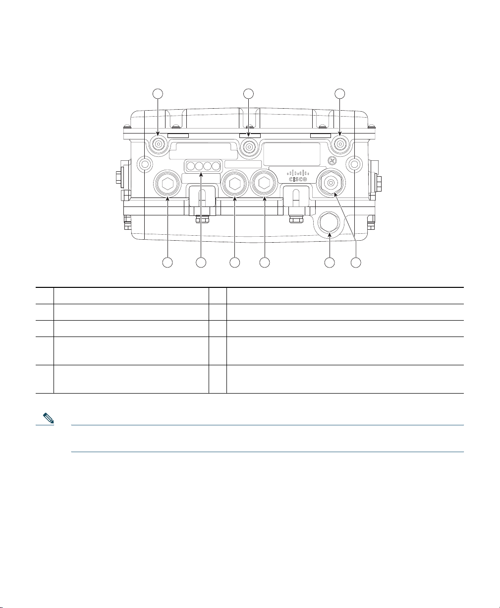
Figure 1 Access Point Bottom Connectors - Models AIR-CAP1552E-x-K9 and AIR-CAP1552H-x-K9
45 6
282137
1 2 3
45
6
789
1 Antenna port 4 6 Fiber port
2 Antenna port 5 7 PoE-out port
3 Antenna port 6 8 LEDs (Status, Up Link, RF1, RF2)
4 AC power connector for model
9 PoE-in port
AIR-CAP1552H-x-K9 only
5 AC power connector for model
AIR-CAP1552E-x-K9 only
Note Antenna ports 1, 2 and 3 are not shown in Figure 1. These ports are reserved for future use
and will be located on the top of the access point.
10
Page 11
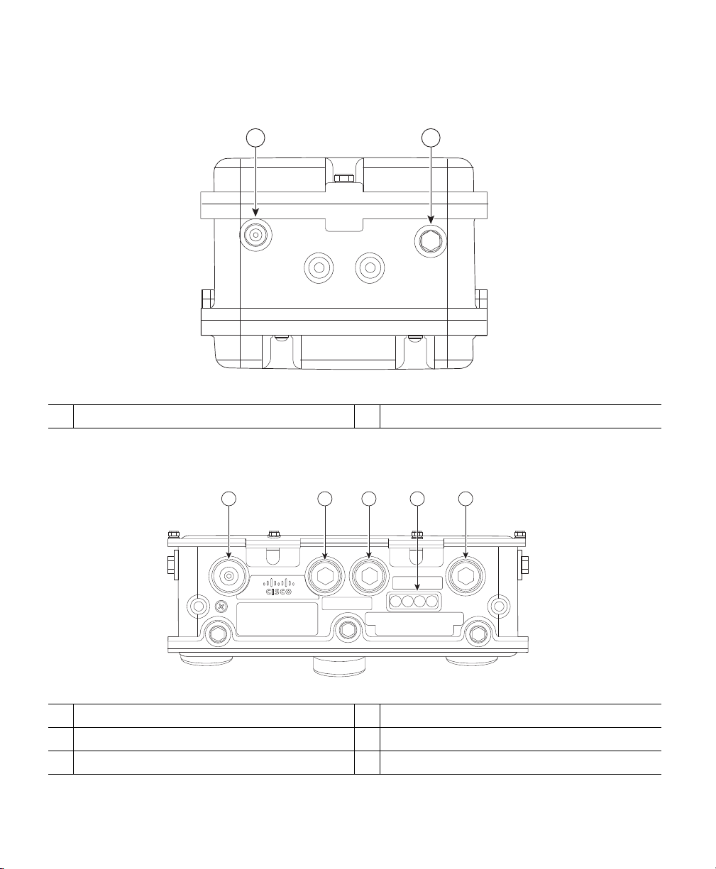
Figure 2 Access Point Left Side Connectors - Models AIR-CAP1552E-x-K9 and AIR-CAP1552H-x-K9
282139
1 2 3 54
1 2
282138
Console Port
1
2
Not used
Figure 3 Access Point Bottom Connectors - Model AIR-CAP1552I-x-K9
1 AC Connector 4 LEDs (Status, Up Link, RF1, RF2)
2 Not used 5 Ethernet backhaul connector
3 Console port
11
Page 12
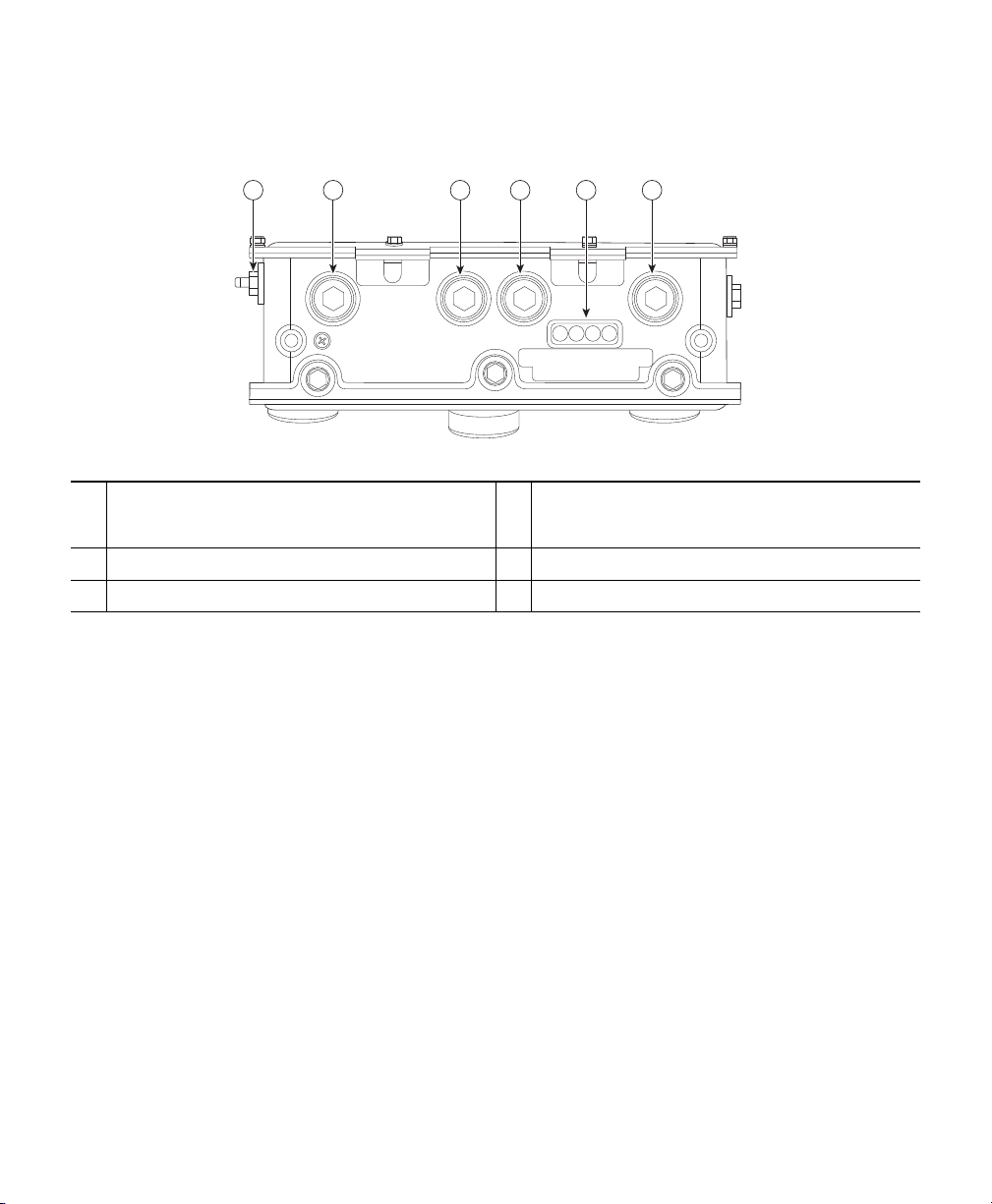
Figure 4 Access Point Bottom and Left Side Connectors - Model AIR-CAP1552C-x-K9
282140
1 2 3 4 65
1 F-Connector adapter (splitter) for cable
(optional)
2 Not used 5 LEDs (Status, Up Link, RF1, RF2)
3 Not used 6 Not used
The RF splitter components are shown in Figure 5.
4 Console port
12
Page 13
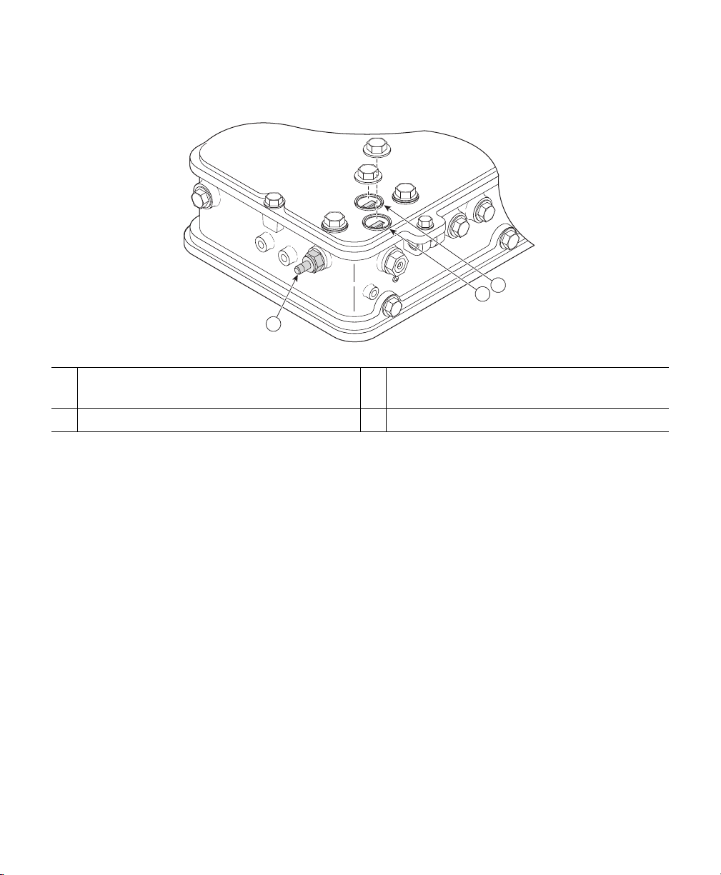
Figure 5 RF Splitter Components
3
1
2
255265
RF splitter attenuator (ATTN)
1
3 F-Connector adapter (splitter) for cable POC
(optional)
2 RF splitter shunt (SHUNT)
Figure 6 shows the access point DC power connector and ground lug.
13
Page 14
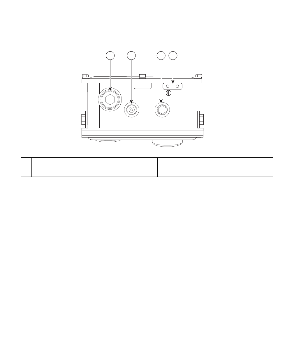
Figure 6 Access Point DC Power Connector and Ground Lug (All Models)
1 3 42
282141
1 DC power port 3 Bracket mounting nut
2 Bracket mounting hole 4 Ground lug location
Radio Operation
The 1552 access point 802.11b/g/n radio is used primarily for local access and its 802.11a/g/n radio
for wireless backhaul in the Mesh.
The 2 GHz b/g/n radio operates in 2.4 GHz ISM band. It supports channels 1-11 in US, 1-13 in Europe,
and 1-13 in Japan. It has two transmitters with a maximum total output power of 25dBm for
802.11b/g/n operation. Output power is configurable to 5 levels. It has three receivers that enables
maximum-ratio combining (MRC).
The 5GHz a/n radio operates in the UNII-2 band (5.25 - 5.35 GHz), UNII-2 Extended/ETSI band (5.47
- 5.725 GHz), and the upper ISM band (5.725 - 5.850 GHz). It has two transmitters with a maximum
total output power of 26 dBm for UNII-2 and Extended/ETSI bands for the A-domain. The total
maximum output power for the upper ISM band is 28 dBm for A-domain. Power settings will change
depending on the regulatory domain. Output power is configurable for 5 power levels in 3 dB steps.
Its three receivers enables maximum-ratio combining (MRC).
The 1552 models C and I access points are equipped with three new integrated dual-band antennas,
with 2 dBi gain at 2.4 GHz and 4 dBi gain at 5 GHz. The antenna works in cable strand mount and
low cost, low profile applications.
14
Page 15

External Antenna Option
Warning
Warning
Warning
The 1552 models E and H access points are equipped with three N-type radio frequency (RF)
connectors (antenna ports 4, 5, and 6) on the bottom of the unit for external antennas to support
multiple input multiple output (MIMO) operation as shown in
models must always be operated with the three external antennas attached. When using the Cisco
Aironet AIR-ANT2547V-N Dual-Band Omnidirectional Antenna, the 2.4- and 5-GHz antennas
connect directly to the access point, as shown in
antennas use vertical polarization. Models 1552E and 1552H access point antennas have 4 dBi gain
at 2.4 GHz and 7 dBi gain at 5 GHz.
In order to comply with radio frequency (RF) exposure limits, the antennas up to 8 dBi
gain for this product should be placed no less than 20cm (8") from your body or nearby
persons. This distance shall be increased to 40cm (16") with antennas that have gain
between 8 and 14 dBi.
Do not locate the antenna near overhead power lines or other electric light or power
circuits, or where it can come into contact with such circuits. When installing the
antenna, take extreme care not to come into contact with such circuits, because they
may cause serious injury or death. For proper installation and grounding of the antenna,
please refer to national and local codes (for example, U.S.:NFPA 70, National Electrical
Code, Article 810, Canada: Canadian Electrical Code, Section 54).
Only trained and qualified personnel should be allowed to install, replace, or service this
equipment.
Statement 1030
Statement 339
Statement 1052
Figure 7. The 1552E and 1552H
Figure 8. The Cisco dual-band omnidirectional
15
Page 16
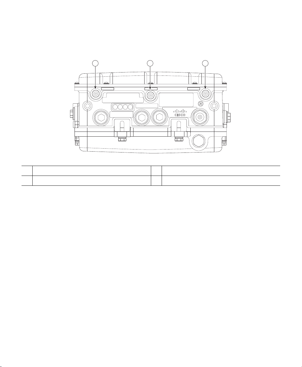
Figure 7 Access Point External Antenna Connectors - Models AP-CAP1552E-x-K9 and Models
45 6
282142
1 2 3
AP-CAP1552H-x-K9
N-Type Connector - Antenna port 4 (TX/RX
1
N-Type Connector - Antenna port 5 (RX)
2
N-Type Connector - Antenna port 6 (TX/RX)
3
16
Page 17
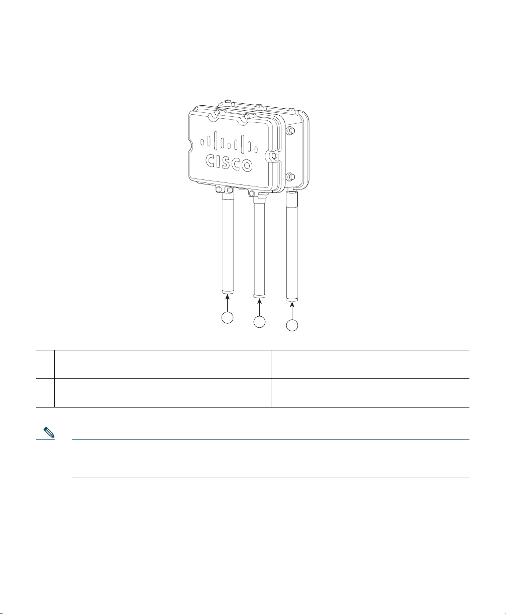
Figure 8 Access Point Dual-Band Omnidirectional Antennas-Installed Only on Models
AIR-CAP1552E-x-K9 and AIR-CAP1552H-x-K9
282145
1
1 Antenna connected to antenna port 4 (Type-N
connector) (TX/RX)
2
3
3 Antenna connected to antenna port 6 (Type-N
connector) (TX/RX)
2 Antenna connected to antenna port 5 (Type-N
connector) (RX only)
Note The FCC limits the amount of power this device can transmit. Power transmitted is a
combination of the amplification of the signal and the antenna gain. The access point has been
designed to operate with the Cisco provided antennas.
17
Page 18

Integrated Antenna Option
The 1552C and 1552I models use the Integrated Low Profile Dual-Band 2.4/5 GHz Dipole Antenna
Array. The antenna contains an array of three dual-band dipole antennas. The three dipole antennas are
contained within this single radome, thereby greatly reducing the antennas visual footprint, and greatly
reducing the possibility of snagging the antenna on the cable bundle, the RF cable, or test cables. The
antennas operate over both 2.4 GHz and 5.25 – 5.85 GHz bands. Each of the three dipole antennas is a
dual-band antenna, covering both the 2.4 – 2.483 GHz band, and the 5.25 – 5.85 GHz bands. The antenna
have a peak gain of about 2 dBi at 2.4 GHz and 4 dBi at 5 GHz. The antenna unit is gray weatherproof
radome for outdoor operation.
The low profile integrated antennas are attached to the bottom of a Cisco access point. The 1552C comes
with the option of a C-bracket for strand mounting. The 1552C mesh access point chassis mounting
brackets and low profile antenna all fit within the 30 cm vertical right-of-way for cable strand-mounted
equipment. The antennas are internally connected to the diplexer ports of the outdoor mesh access point
2.4/5 GHz 2x3 MIMO radios.
Figure 9 shows an installed integrated low-profile dual-band (2.4 GHz and 5.25 GHz) 3-element array
antenna. It is available on models AIR-CAP1552I-x-K9 and AIR-CAP1552C-x-K9.
18
Page 19

Figure 9 Access Point Cisco Integrated Low-Profile Dual-Band 2.4/5 GHz Omni Antenna Array –
209188
1
4
3
2
Built-In on Models AIR-CAP1552C-x-K9 and AIR-CAP1552I-x-K9
Integrated Low-Profile Dual-Band 2.4/5 GHz
Omni Antenna Array Unit - PID
1
Antenna element (TX/RX)
3
AIR-ANT2547V-N
Antenna element (RX only)
2
Antenna element (TX/RX)
4
Antenna Mounting Configurations
The selection of the antenna is determined in the configuration of the product. Depending on the 1552
models selected, the antennas can be mounted on a pole and/or cable strand mounted. Refer to the
Cisco Aironet 1550 Outdoor Mesh Access Point Hardware Installation Guide for detailed information
on mounting the antennas.
19
Page 20

Power
Warning
Warning
Warning
The 1550 series access point supports the following power sources:
• AC power—90 to 480 VAC, 47 to 63 Hz
• Streetlight power tap
• Quazi-AC power-over-cable (POC)—40 to 90 VAC, 47 to 63 Hz, quasi-square wave
• External 12 VDC power
• Power-over-Ethernet— power injector (same as 1520)
• Internal 6 ampere-hour battery backup
Caution Do not place the power injector in an unprotected outdoor environment because water
Installation of the equipment must comply with local and national electrical codes.
Statement 1074
This equipment must be externally grounded using a customer-supplied ground wire
before power is applied. Contact the appropriate electrical inspection authority or an
electrician if you are uncertain that suitable grounding is available.
Do not work on the system or connect or disconnect cables during periods of lightning
activity.
could get into the power injector and cause a short circuit and possible fire.
Statement 1001
Statement 366
Warning
20
Connect the unit only to DC power source that complies with the Safety Extra-Low
Voltage (SELV) requirements in IEC 60950 based safety standards
Statement 1033
Page 21

The 1550 series access point can be connected to more than one power source. The access point detects
available input sources and switches to the preferred power source using the following prioritization:
• AC or POC power
• External DC power
• Power injector PoE power (same as 1520)
• Internal battery power
Warning
Warning
Caution To provide inline PoE, you must use the 1500 power injector (AIR-PWRINJ1500-2=).
Caution Do not install the power injector and the power outdoors. They must be installed indoors.
Caution When the access point is installed outdoors or in a wet or damp location, the AC branch
Three AC power cord options are available:
• 40-ft (12.2-m) power cord for installations in the US and Canada. One end of the power cord is
This unit might have more than one power supply connection. All connections must be
removed to de-energize the unit.
To reduce the risk of fire, use only No. 26 AWG or larger telecommunication line cord.
Statement 1023
Other power injectors, PoE switches, and 802.3af power sources cannot provide adequate
power, which may cause the access point to malfunction and cause over-current
conditions at the power source. You must ensure that the switch port connected to the
access point has PoE turned off.
circuit that is powering the access point should be provided with ground fault protection
(GFCI), as required by Article 210 of the National Electrical Code (NEC).
Statement 1028
terminated with an access point AC power connector and the other end is terminated with an
AC plug (AIR-CORD-R3P-40NA=).
• 40-ft (12.2-m) power cord for use outside the US and Canada. One end of the power cord is
terminated with an access point AC power connector and the other end is unterminated.
(AIR-CORD-R3P-40UE=).
21
Page 22

• 4-ft (1.2-m) streetlight power tap adapter for light pole installations in the US and Canada
(AIR-PWR-ST-LT-R3P=).
Ethernet (PoE) Ports
The access point supports an Ethernet uplink port (PoE-In) and a PoE out port (PoE-Out). The access
point Ethernet uplink port uses an RJ-45 connector (with weatherproofing) to link the access point to
the 10BASE-T, 100BASE-T, or 1000BASE-T network. The Ethernet cable is used to send and receive
Ethernet data and to optionally supply inline 56-VDC power from the power injector. The minimum
length of this cable must be not less than 10 feet (3 meters).
The access point PoE-Out Ethernet port uses an RJ-45 connector (with weatherproofing) to provide
LAN connectivity and IEEE 802.3af power to a peripheral customer device, such as a camera or sensor
gateway. The Ethernet MAC addresses are printed on a label on the bottom of the access point under
the LEDs.
Tip The access point senses the Ethernet and power signals and automatically switches internal
circuitry to match the cable connections.
Caution To provide inline PoE, you must use the 1550 series power injector. Other power
injectors, PoE switches, and 802.3af power sources can not provide adequate power,
which may cause the access point to malfunction and cause possible over-current
conditions at the power source.
Cable Option
The factory-orderable cable option provides a cable modem and Power-over-Cable (POC) capabilities
for the access point for high-speed data transfer and Internet access. When the cable option is selected
and installed, the access point uses its F-type cable connector to receive both data and power. Data is
passed between wireless clients on the mesh network to the cable company network via the internal
cable modem of the access point. In this configuration, the access point receives operating power from
the cable. For detailed installation information, see the Cisco Aironet 1550 Series Outdoor Access
Point Hardware Installation Guide. Configuration information can be found in the controller
configuration guide of the controller you are using.
22
Page 23

Fiber Option
Warning
The factory-orderable fiber option provides a fiber input and output capability. Fiber data is
transmitted and received over a single-strand fiber cable, which is connected to the access point using
these small-factor pluggable (SFP) modules:
• 100BASE-BX10-U fiber Rugged SFP module
• 1000BASELX single-mode Rugged SFP module
• 1000BASESX multimode Rugged SFP module
Note SFP modules are not hot-swappable.
One fiber connection is available on both the 1552E and 1552H access points. The fiber connection
is on the bottom of both the 1552E and 1552H access points (shown on
to the network controller through the fiber connection via a fiber capable switch. For detailed
installation information about the fiber option, see the Cisco Aironet 1550 Series Outdoor Mesh
Access Point Hardware Installation Guide. Configuration information can be found in the controller
configuration guide of the controller you are using.
Class 1 laser product.
Statement 1008
Figure 1). Client data is passed
6 Network Deployment Examples
The access point is a wireless device designed for wireless client access and point-to-point bridging,
point-to-multipoint bridging, and point-to-multipoint mesh wireless connectivity. The access point
provides 5-GHz backhaul capability to link with another access point to reach a wired network
connection or to provide repeater operations for other access points.
The access point plays two primary radio roles: a root access point (hereafter called a RAP) or a mesh
(non-root) access point (hereafter called a MAP), which is the default role of all access points. When
the access point has a fiber or wired Ethernet or cable connector connection to the controller (through
a switch), the radio role is called a RAP. In order to be considered a RAP, the access point must be
configured as a RAP. A RAP is a parent node to any bridging or mesh network. A controller can
support one or more RAPs, each one parenting the same or different wireless networks. There can be
more than one RAP for the same mesh network for redundancy. RAPs and MAPs can support wireless
clients on the 2.4-GHz and 5-GHz band. Client access on 5-GHz is called universal client access.
23
Page 24

When the access point does not have a wired Ethernet connection to the controller (through a switch),
148438
(5.8 Ghz)
(2.4 Ghz)
the radio role is called a MAP. The MAPs have a wireless connection (through the backhaul interface)
to other MAPs and finally to a RAP which has an Ethernet connection through a switch to the
controller. MAPs may also have a wired Ethernet connection to a local LAN and serve as a bridge
endpoint for that LAN (using a point-to-point or point-to-multipoint bridge connection).
Wireless Backhaul
The access point supports wireless backhaul capability using the 5-GHz radio to bridge to another
access point to reach a wired network connection to a controller as shown in
point connected to the wired network is considered a RAP in this configuration. The remote access
point is considered a MAP and transfers wireless client traffic to the RAP for transfer to the wired
network. Control And Provisioning of Wireless Access Points (CAPWAP) control traffic is also
transferred over this bridged link.
Figure 10 Access Point Backhaul Example
Figure 10. The access
Point-to-Point Bridging
The access points can be used to extend a remote network by using the 5-GHz backhaul radio to bridge
the two network segments as shown in
bridging on the controller for each access point. By default this capability is turned-off for all access
points.
Wireless client access is supported; however, if bridging between tall buildings, the 2.4-GHz wireless
coverage area may be limited and possibly not suitable for direct wireless client access.
24
Figure 11. To support Ethernet bridging, you must enable
Page 25

Figure 11 Access Point Point-to-Point Bridging Example
255495
(5 GHz)
255494
(5 GHz)
(5 GHz)
Point-to-Multipoint Bridging
The access points can be used as a RAP to connect multiple remote MAPs with their associated wired
networks. By default this capability is turned-off for all access points. To support Ethernet bridging,
you must enable bridging on the controller for each access point. Wireless client access can be provided
over the bridging link; however, if bridging between tall buildings, the 2.4-GHz wireless coverage area
may be limited and possibly not suitable for direct wireless client access.
Figure 12 illustrates an example of access point-to-multipoint bridging.
Figure 12 Access Point Point-to-Multipoint Bridging Example
25
Page 26

Point-to-Multipoint Mesh Network
148441
WCS
Network
RAP
MAP 1
MAP 2
MAP 3
MAP 4
MAP 6
MAP 5
MAP 7
MAP 8
MAP 9
The access point is typically deployed in a mesh network configuration. In a typical mesh deployment,
one or more RAPs have a wired network connection through a switch to a controller. Other remote
MAPs without wired network connections use the backhaul feature to optimally link to a RAP that is
connected to the wired network. In the mesh network, the links between the access points are referred
to as the backhaul links.
Intelligent wireless routing is provided by the Adaptive Wireless Path protocol (AWPP). This enables
each MAP to identify its neighbors and intelligently choose the optimal path to the RAP with the wired
network connection by calculating the cost of each path in terms of signal strength and the number of
hops required to get to a controller with signal strength given priority since signal strength determines
the data rate available for backhaul.
Figure 13 illustrates a typical mesh configuration using access points.
Figure 13 Typical Mesh Configuration Using Access Points
26
Page 27

Layer 3 Network Operation
The access points support Layer 3 network operation. Access points and controllers in Layer 3
configurations use IP addresses and UDP packets, which can be routed through large networks.
Layer 3 operation is scalable and is the recommended operation. Figure 14 illustrates a typical Layer-3
wireless network configuration containing access points and a controller.
Figure 14 Typical Layer 3 Access Point Network Configuration Example
7 Preparing the Access Point
The access point is a radio device which is susceptible to common causes of interference that can
reduce throughput and range. Follow these basic guidelines to ensure the best possible performance:
• For information on planning and initially configuring your Cisco mesh network, refer to the Cisco
Wireless Mesh Access Points, Design and Deployment Guide, Release 7.0. These documents are
available on cisco.com.
• Do not install the access point in an area where structures, trees, or hills obstruct radio signals to
and from the access point.
• You can install the access point at any height, but best throughput is achieved when the access
points are mounted at the same height.
Note To perform path loss calculation and to determine how far apart to install access points,
consult an RF planning expert.
27
Page 28

Site Surveys
Cisco recommends that you perform a site survey before installing the equipment. A site survey reveals
problems that can be resolved before the network is operational. Because 802.11a/b/g/n operates in an
unlicensed spectrum, there may be sources of interference from other 802.11a wireless devices
(especially in multi-tenant buildings) that could degrade your 802.11 signals. A site survey can
determine if such interference exists at the time of deployment.
A proper site survey involves temporarily setting up mesh links and taking measurements to determine
whether your antenna calculations are accurate. Determine the correct locations and antenna types
before you drill holes and route cables and mounting equipment.
Tip When power is not readily available during a site survey, use an unrestricted power supply
(UPS) to temporarily power the mesh link.
Consider the following operating and environmental conditions when performing a site survey:
• How far is your wireless link?
• Has a previous site survey been conducted?
• Do you have a clear Fresnel zone between the access points or radio line of sight?
• What is the minimum acceptable data rate within the link?
• Do you have the correct antenna (if more than one antenna is being offered)?
• Do you have access to both of the mesh site locations?
• Do you have the proper permits, if required?
• Are you following the proper safety procedures and practices?
• Have you configured the access points before you go onsite? It is always easier to resolve
configurations or device problems first.
• Do you have the proper tools and equipment to complete your survey?
Avoiding Damage to Radios in a Testing Environment
The radios on outdoor units (bridges) have higher transmit power levels than radios on indoor units
(access points). When you test radios in a link, you must avoid exceeding the maximum receive input
level of the receiver. At levels higher than the normal the operating range and packet error rate (PER)
performance of the receiver is degraded. At even higher levels, the receiver can be permanently
damaged.
28
Page 29

To avoid receiver damage and PER degradation, you can use one of the following techniques:
• Separate the omnidirectional antennas by at least 2 ft (0.6 m) to avoid receiver damage or by at
least 25 ft (7.6 m) to avoid PER degradation.
• Reduce the configured transmit power to the minimum level.
• Cable the radios together using a combination of attenuators, combiners, or splitters to achieve a
total attenuation of at least 60 dB.
For a radiated test bed, the following equation describes the relationships among transmit power,
antenna gain, attenuation, and receiver sensitivity:
txpwr + tx antenna gain + rx ant gain - [attenuation due to antenna spacing] < max rx
input level
Where:
txpwr = Radio transmit power level
tx gain = transmitter antenna gain
rx gain = receiver antenna gain
For a conducted test bed, the following equation describes the relationships among transmit power,
antenna gain, and receiver sensitivity:
txpwr - [attenuation due to coaxial RF Attenuator components] < max rx input level
(0
dbm)
Caution Under no circumstances should you connect the antenna port from one access point to the
antenna port of another access point without using an RF attenuator. If you connect
antenna ports you must not exceed the maximum survivable receive level of 0 dBm. Never
exceed 0 dBm or damage to the access point can occur. Using attenuators, combiners, and
splitters having a total of at least 60 dB of attenuation ensures that the receiver is not
damaged and PER performance is not degraded.
29
Page 30

Before You Begin
Warning
Before you begin the installation process:
• Become familiar with the procedures for mounting the access point.
• Become familiar with the access point connections (Figure 1 on page 10, Figure 2 on page 11, and
Figure 6 on page 14).
• Verify that the switch you are using to connect the controller is configured properly.
Note For additional installation, mounting and safety information for the outdoor mesh access
Read the installation instructions before connecting the system to the power source.
Statement 1004
point, see the Cisco Aironet 1550 Series Outdoor Mesh Access Point Hardware Installation
Guide, which is available on Cisco.com, and
Outdoor Mesh Access Points, which accompanies this guide.
Safety Warnings for Cisco Aironet 1520 Series
8 Deploying the Access Point
Warning
The access point is deployed on Layer 3 networks. Layer 3 is the default mode for a newly configured
wireless LAN controller. This guide assumes that you will be deploying your access point on a Layer
3 network and a DHCP server is available.
Before deploying the access point, make sure the controller to which the access point will associate is
properly configured by performing the following operations:
• Make sure that the wireless LAN controller is set to Layer 3 mode
• Verify the wireless LAN controller software version
• Record the access point BVI MAC address
• Enter the access point BVI MAC address to the wireless LAN controller filter list
Do not operate the unit near unshielded blasting caps or in an explosive environment
unless the device has been modified to be especially qualified for such use.
Statement 364
Verifying the Wireless LAN Controller Mode
Follow these steps to verify that the wireless LAN controller mode is set to Layer 3:
30
Page 31

Step 1 Open your web-browser and enter the IP address of your wireless LAN controller. Be sure to
precede the IP address with https://. A login screen appears.
Step 2 Enter your username and password. The default case-sensitive username and password are
admin and admin. The Summary page appears.
Step 3 From the top menu bar, click CONTROLLER. The Controller General page appears.
Step 4 Verify that the CAPWAP Transport Mode is set to Layer 3. If it is not, change it to Layer 3
and click Apply.
Step 5 Save any changes you made.
Step 6 From the menu bar, click MONITOR to return to the Monitor Summary page.
Verifying the Wireless LAN Controller Software Version
On the Summary page, you can verify the software version that the wireless LAN controller is running.
If a version update is necessary, refer to the appropriate controller configuration documentation.
Recording the Access Point MAC Address
Use a text file to record the MAC address of all the access points you intend to deploy in your network.
Having a file of access point MAC addresses will be of considerable value for future testing. While you
are compiling the list, you might want to change the name of the access point to something you can
easily remember. The name can contain up to 32 characters. The following example, fisher_street:ea:co
contains the last four HEX characters of the access point MAC address.
Adding the Access Point MAC Address to the Wireless LAN Controller Filter List
The wireless LAN controller maintains an access point authorization MAC address list and responds
to discovery requests from access points on that list. To add the access point MAC address (or MAC
addresses) to the Wireless LAN controller filter list, follow these steps:
Step 1 If you are not logged onto the wireless LAN controller, log on now. The Summary page
appears.
Step 2 On the menu bar, click SECURITY. The Security RADIUS Authentication Server page
appears.
Step 3 Under AAA in the left frame, click MAC Filtering. The Security MAC Filtering page appears.
Step 4 Click New. The MAC Filters New page appears.
31
Page 32

Step 5 Enter the MAC address of the access point in the MAC Address field. You can also use the
config macfilter add command to add a MAC filter entry to the controller.
Step 6 Select a WLAN ID or Any WLAN from the WLAN ID pop-up menu.
Step 7 Enter a description (32 characters maximum) of the access point in the Description field.
Step 8 Choose an interface from the Interface Name pop-up menu.
Step 9 Click Apply.
Step 10 Repeat this process to add other access points to the list.
Note You can also use the controller CLI command config macfilter add to add a MAC
filter entry on the controller.
Step 11 On the menu bar, click Monitor to return to the Monitor Summary page.
Verifying Controller Association
To verify that your access point is associated to the wireless LAN controller, perform these steps:
Step 1 Log into your controller web interface (https) using a web browser.
Step 2 Click Wireless and verify that your access point MAC address is listed under Ethernet MAC.
Step 3 Log out of the controller and close your web browser.
Deployment Notes
Using a DHCP Server in a Layer 3 Mesh Network
To use a DHCP server in a Layer 3 mesh network, make sure the wireless LAN controller is in Layer
3 mode. You must also configure DHCP option 43 on the DHCP server. After the controller is
restarted, the access point receives IP addresses from the DHCP server.
32
Page 33

Configuring DHCP Option 43
You can use DHCP Option 43 to provide a list of controller IP addresses to the access points, enabling
each access point to find and join a controller. This section contains a DHCP Option 43 configuration
example on a Microsoft Windows 2003 Enterprise DHCP server for use with Cisco Aironet
lightweight access points.
Additional information about Microsoft DHCP Option 43 is available on Cisco.com at the following
URL:
http://www.cisco.com/en/US/tech/tk722/tk809/technologies_configuration_example09186a0080871
4fe.shtml
DHCP Option 43 server implementation information for Cisco IOS is available at cisco.com at the
following URL:
http://www.cisco.com/en/US/docs/wireless/technology/controller/deployment/guide/dep.html#wp106
8287
Note In DHCP Option 43, you should use the IP address of the controller management interface.
Note DHCP Option 43 is limited to one access point type per DHCP pool. You must configure a
separate DHCP pool for each access point type.
Cisco Aironet 1000 and 1500 (1505 and 1510) series access points use a comma-separated string
format for DHCP Option 43. Other Cisco Aironet access points use the type-length-value (TLV)
format for DHCP Option 43. DHCP servers must be programmed to return the option based on the
DHCP Vendor Class Identifier (VCI) string (DHCP Option 60) of the access point. The VCI strings for
Cisco access points capable of operating in lightweight mode are listed in
Table 1:
Ta b l e 1 Lightweight Access Point VCI Strings
Access Point Vendor Class Identifier (VCI)
Cisco Aironet 1000 Series Airespace.AP1200
Cisco Aironet 1100 Series Cisco AP c1100
Cisco Aironet 1130 Series Cisco AP c1130
Cisco Aironet 1200 Series Cisco AP c1200
Cisco Aironet 1240 Series Cisco AP c1240
Cisco Aironet 1250 Series Cisco AP c1250
33
Page 34

Access Point Vendor Class Identifier (VCI)
Cisco Aironet 1300 Series Cisco AP c1300
Cisco Aironet 1500 Series Cisco AP c1500
1
Cisco AP.OAP15002, Cisco AP.LAP15102, or
Cisco AP.LAP1505
Airespace.AP1200
2
3
Cisco Aironet 1520 Series Cisco AP c1520
Cisco Aironet 1550 Series Cisco AP c1550
1. For controller release 4.1 or later.
2. For controller release 4.0, the VCI depends on the model.
3. For controller release 3.2.
The format of the TLV block for 1100, 1130, 1200, 1240, 1250, 1300, 1520, and 1552 access points
are listed below:
• Type: 0xf1 (decimal 241)
• Length: Number of controller IP addresses * 4
• Value: List of WLC management interfaces
Configuring Option 43 for Cisco 1000, 1500, and 1550 Series Access Points
To configure DHCP Option 43 for Cisco 1000, 1500, and 1550 series access points in the embedded Cisco
IOS DHCP server, follow these steps:
Step 1 Enter configuration mode at the Cisco IOS CLI.
Step 2 Create the DHCP pool, including the necessary parameters such as default router and name server.
The commands used to create a DHCP pool are as follows:
ip dhcp pool pool name
network IP Network Netmask
default-router Default router
dns-server DNS Server
Where:
pool name is the name of the DHCP pool, such as AP1000.
IP Network is the network IP address where the controller resides, such as
10.0.15.1
Netmask is the subnet mask, such as 255.255.255.0
Default router is the IP address of the default router, such as 10.0.0.1
DNS Server is the IP address of the DNS server, such as 10.0.10.2
34
Page 35

Step 3 Add the Option 60 line using the following syntax:
option 60 ascii “VCI string”
For the VCI string, use the value from Table 1. The quotation marks must be included.
Step 4 Add the option 43 line using the following syntax:
option 43 ascii “Comma Separated IP Address List”
For example, if you are configuring Option 43 for Cisco 1000, 1500, or 1550 series access
points using the controller IP addresses 10.126.126.2 and 10.127.127.2, add the following
line to the DHCP pool in the Cisco IOS CLI:
option 43 ascii “10.126.126.2,10.127.127.2”
The quotation marks must be included.
Configuring Option 43 for Cisco 1100, 1130, 1200, 1240, 1250, 1300, 1520, and 1550 Series Access Points
To configure DHCP Option 43 for Cisco 1100, 1130, 1200, 1240, 1250, 1300, 1520, and 1550 series access
points in the embedded Cisco IOS DHCP server, follow these steps:
Step 1 Enter configuration mode at the Cisco IOS CLI.
Step 2 Create the DHCP pool, including the necessary parameters such as default router and name server.
The commands used to create a DHCP pool are as follows:
ip dhcp pool pool name
network IP Network Netmask
default-router Default router
dns-server DNS Server
Where:
pool name is the name of the DHCP pool, such as AP1550.
IP Network is the network IP address where the controller resides, such as
10.0.15.1
Netmask is the subnet mask, such as 255.255.255.0
Default router is the IP address of the default router, such as 10.0.0.1
DNS Server is the IP address of the DNS server, such as 10.0.10.2
Step 3 Add the Option 60 line using the following syntax:
option 60 ascii “VCI string”
For the VCI string, use the value from Table 1. The quotation marks must be included.
35
Page 36

Step 4 Add the option 43 line using the following syntax:
Tested To Comply
With FCC Standards
FOR HOME OR OFFICE USE
option 43 hex hex string
The hex string is assembled by concatenating the TLV values shown below:
Type + Length + Value
Type is always f1(hex). Length is the number of controller management IP addresses times 4
in hex. Valu e is the IP address of the controller listed sequentially in hex.
For example, suppose that there are two controllers with management interface IP addresses,
10.126.126.2 and 10.127.127.2. The type is f1(hex). The length is 2 * 4 = 8 = 08 (hex). The
IP addresses translate to 0a7e7e02 and 0a7f7f02. Assembling the string then yields
f1080a7e7e020a7f7f02. The resulting Cisco IOS command added to the DHCP scope is listed
below:
option 43 hex f1080a7e7e020a7f7f02
9 Declarations of Conformity and Regulatory Information
This section provides declarations of conformity and regulatory information for the Cisco Aironet
1550 Series Access Point.
Manufacturers Federal Communication Commission Declaration of Conformity Statement
Page 37

Models Certification Numbers
AIR-CAP1552E-A-K9
AIR-CAP1552H-A-K9
AIR-CAP1552C-A-K9
AIR-CAP1552I-A-K9
AIR-CAP1552EU-A-K9
AIR-CAP1552CU-A-K9
Manufacturer:
Cisco Systems, Inc.
170 West Tasman Drive
San Jose, CA 95134-1706
USA
This device complies with Part 15 rules. Operation is subject to the following two conditions:
1. This device may not cause harmful interference, and
2. This device must accept any interference received, including interference that may cause undesired
operation.
This equipment has been tested and found to comply with the limits of a Class B digital device,
pursuant to Part 15 of the FCC Rules. These limits are designed to provide reasonable protection
against harmful interference when the equipment is operated in a residential environment. This
equipment generates, uses, and radiates radio frequency energy, and if not installed and used in
accordance with the instructions, may cause harmful interference. However, there is no guarantee that
interference will not occur. If this equipment does cause interference to radio or television reception,
which can be determined by turning the equipment off and on, the user is encouraged to correct the
interference by one of the following measures:
• Reorient or relocate the receiving antenna.
• Increase separation between the equipment and receiver.
• Connect the equipment to an outlet on a circuit different from which the receiver is connected.
• Consult the dealer or an experienced radio/TV technician.
FCC ID: LDK102074P
Caution The Part 15 radio device operates on a non-interference basis with other devices operating
at this frequency when using the integrated antennas. Any changes or modification to the
product (including the use of non-Cisco antennas specified for this model) provided not
expressly approved by Cisco could void the user’s authority to operate this device.
37
Page 38

VCCI Statement for Japan
Warning
This is a Class B product based on the standard of the Voluntary Control
Council for Interference from Information Technology Equipment (VCCI). If this
is used near a radio or television receiver in a domestic environment, it may
cause radio interference. Install and use the equipment according to the
instruction manual.
38
Page 39
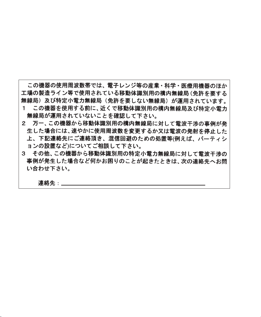
Guidelines for Operating Cisco Aironet Access Points in Japan
03-6434-6500
208697
This section provides guidelines for avoiding interference when operating Cisco Aironet access points
in Japan. These guidelines are provided in both Japanese and English.
Japanese Translation
English Translation
This equipment operates in the same frequency bandwidth as industrial, scientific, and medical devices
such as microwave ovens and mobile object identification (RF-ID) systems (licensed premises radio
stations and unlicensed specified low-power radio stations) used in factory production lines.
1. Before using this equipment, make sure that no premises radio stations or specified low-power
radio stations of RF-ID are used in the vicinity.
2. If this equipment causes RF interference to a premises radio station of RF-ID, promptly change
the frequency or stop using the device; contact the number below and ask for recommendations
on avoiding radio interference, such as setting partitions.
3. If this equipment causes RF interference to a specified low-power radio station of RF-ID, contact
the number below.
Contact Number: 03-6434-6500
39
Page 40
Statement 371—Power Cable and AC Adapter
English Translation
When installing the product, please use the provided or designated connection cables/power cables/AC
adaptors. Using any other cables/adaptors could cause a malfunction or a fire. Electrical Appliance and
Material Safety Law prohibits the use of UL-certified cables (that have the “UL” shown on the code)
for any other electrical devices than products designated by CISCO. The use of cables that are certified
by Electrical Appliance and Material Safety Law (that have “PSE” shown on the code) is not limited
to CISCO-designated products.
Industry Canada
Canadian Compliance Statement
AIR-CAP1552E-A-K9
AIR-CAP1552H-A-K9
AIR-CAP1552C-A-K9
AIR-CAP1552I-A-K9
AIR-CAP1552EU-A-K9
AIR-CAP1552CU-A-K9
This Class B Digital apparatus meets all the requirements of the Canadian Interference-Causing
Equipment Regulations.
Cet appareil numerique de la classe B respecte les exigences du Reglement sur le material broilleur du
Canada.
40
IC: 2461B-102074P
Page 41

This device complies with Class B Limits of Industry Canada. Operation is subject to the following
two conditions:
1. This device may not cause harmful interference, and
2. This device must accept any interference received, including interference that may cause undesired
operation.
Cisco Aironet Access Points are certified to the requirements of RSS-210. The use of this device in a
system operating either partially or completely outdoors may require the user to obtain a license for
the system according to the Canadian regulations. For further information, contact your local Industry
Canada office.
This device has been designed to operate with antennas having a maximum gain of 4 dBi for 2.4 GHz
and 7 dBi for 5 GHz. Antennas having a gain greater than 6 dB are strictly prohibited for use with this
device. The required antenna impedance is 50 ohms.
To reduce potential radio interference to other users, the antenna type and its gain should be so chosen
that the equivalent isotropically radiated power (EIRP) is not more than that permitted for successful
communication.
European Community, Switzerland, Norway, Iceland, and Liechtenstein
Models:
AIR-CAP1552E-E-K9
AIR-CAP1552H-E-K9
AIR-CAP1552C-E-K9
AIR-CAP1552I-E-K9
AIR-CAP1552EU-A-K9
AIR-CAP1552CU-A-K9
41
Page 42

Declaration of Conformity with regard to the R&TTE Directive 1999/5/EC & Medical Directive 93/42/EEC
42
Page 43

The following standards were applied:
EMC—EMC-EN 301.489-1 v1.8.1; EN 301.489-17 v2.1.1
Health & Safety—EN60950-1: 2005; EN 50385: 2002
Radio—EN 300 328 v 1.7.1; EN 301.893 v 1.5.1
The conformity assessment procedure referred to in Article 10.4 and Annex III of Directive 1999/5/EC
has been followed.
43
Page 44

This device also conforms to the EMC requirements of the Medical Devices Directive 93/42/EEC.
Note This equipment is intended to be used in all EU and EFTA countries. Outdoor use may be
restricted to certain frequencies and/or may require a license for operation. For more details,
contact Cisco Corporate Compliance.
The product carries the CE Mark:
Declaration of Conformity for RF Exposure
United States
This system has been evaluated for RF exposure for Humans in reference to ANSI C 95.1 (American
National Standards Institute) limits. The evaluation was based on ANSI C 95.1 and FCC OET Bulletin
65C rev 01.01. The minimum separation distance from the antenna to general bystander is 8" (20cm)
for antenna gains up to 8 dBi and 16" (40cm) for antenna gains from 8.1 to 14 dbi to maintain
compliance.
Canada
This system has been evaluated for RF exposure for Humans in reference to ANSI C 95.1 (American
National Standards Institute) limits. The evaluation was based on RSS-102 Rev 2. The minimum
separation distance from the antenna to general bystander is 8" (20cm) for antenna gains up to 8 dBi
and 16" (40cm) for antenna gains from 8.1 to 14 dbi to maintain compliance.
European Union
This system has been evaluated for RF exposure for Humans in reference to the ICNIRP (International
Commission on Non-Ionizing Radiation Protection) limits. The evaluation was based on the EN
50385 Product Standard to Demonstrate Compliance of Radio Base stations and Fixed Terminals for
Wireless Telecommunications Systems with basic restrictions or reference levels related to Human
Exposure to Radio Frequency Electromagnetic Fields from 300 MHz to 40 GHz. The minimum
separation distance from the antenna to general bystander is 8" (20cm) for antenna gains up to 8 dBi
and 16" (40cm) for antenna gains from 8.1 to 14 dbi.
44
Page 45

Australia
This system has been evaluated for RF exposure for Humans as referenced in the Australian Radiation
Protection standard and has been evaluated to the ICNIRP (International Commission on
Non-Ionizing Radiation Protection) limits. The minimum separation distance from the antenna to
general bystander is 8" (20cm) for antenna gains up to 8 dBi and 16" (40cm) for antenna gains from
8.1 to 14 dbi.
Administrative Rules for Cisco Aironet Access Points in Taiwan
This section provides administrative rules for operating Cisco Aironet access points in Taiwan. The
rules for all access points are provided in both Chinese and English.
Chinese Translation
45
Page 46

English Translation
Administrative Rules for Low-power Radio-Frequency Devices
Article 12
For those low-power radio-frequency devices that have already received a type-approval, companies,
business units or users should not change its frequencies, increase its power or change its original
features and functions.
Article 14
The operation of the low-power radio-frequency devices is subject to the conditions that no harmful
interference is caused to aviation safety and authorized radio station; and if interference is caused, the
user must stop operating the device immediately and can't re-operate it until the harmful interference
is clear.
The authorized radio station means a radio-communication service operating in accordance with the
Communication Act.
The operation of the low-power radio-frequency devices is subject to the interference caused by the
operation of an authorized radio station, by another intentional or unintentional radiator, by
industrial, scientific and medical (ISM) equipment, or by an incidental radiator.
Chinese Translation
46
Page 47

English Translation
Low-power Radio-frequency Devices Technical Specifications
4.7 Unlicensed National Information Infrastructure
4.7.6 The U-NII devices shall accept any interference from legal communications and shall not
interfere the legal communications. If interference is caused, the user must stop operating
the device immediately and can't re-operate it until the harmful interference is clear.
4.7.7 Manufacturers of U-NII devices are responsible for ensuring frequency stability such that
an emission is maintained within the band of operation under all conditions of normal
operation as specified in the user manual.
Operation of Cisco Aironet Access Points in Brazil
This section contains special information for operation of Cisco Aironet access points in Brazil.
Access Point Models
AIR-CAP1552E-N-K9
AIR-CAP1552H-N-K9
AIR-CAP1552C-N-K9
AIR-CAP1552EU-A-K9
AIR-CAP1552CU-A-K9
Regulatory Information
Figure 15 contains Brazil regulatory information for the access point models identified in the previous
section.
47
Page 48

Figure 15 Reglatory Information for Brazil
Portuguese Translation
Este equipamento opera em caráter secundário, isto é, não tem direito a proteção contra interferência
prejudicial, mesmo de estações do mesmo tipo, e não pode causar interferência a sistemas operando
em caráter primário.
English Translation
This equipment operates on a secondary basis and consequently must accept harmful interference,
including interference from stations of the same kind. This equipment may not cause harmful
interference to systems operating on a primary basis.
Declaration of Conformity Statements
All the Declaration of Conformity statements related to this product can be found at the following
location:
48
http://www.ciscofax.com.
Page 49

10 In Case of Difficulty
Help is available from Cisco should you experience difficulties; however, before contacting Cisco, look
for a solution to your problem in the following places:
• The Troubleshooting section of this guide
• The troubleshooting section of the Cisco Aironet 1550 Series Outdoor Mesh Access Point
Hardware Installation Guide
• The Troubleshooting a Mesh Network troubleshooting guide found on cisco.com at
http://www.cisco.com/en/US/products/ps8368/prod_troubleshooting_guides_list.html
• The Tools and Resources section on the Technical Support and Documentation page at cisco.com
Follow these steps to contact the Technical Assistance Center on cisco.com:
Step 1 Open your browser and go to http://www.cisco.com/.
Step 2 Click Support. The Support page appears.
Step 3 Choose the link that best serves your support requirements.
Note Click My Tech Support if you are a registered user.
Step 4 Follow the instructions on the page.
Troubleshooting
Caution No serviceable parts inside. Do not open.
This section provides troubleshooting procedures for basic problems with the access point. For the
most up-to-date, detailed troubleshooting information, refer to the Cisco Support website at
cisco.com.
49
Page 50

Guidelines for Using the Access Point
You should keep these guidelines in mind when you use the access point:
• The access points can only communicate with controllers and cannot operate independently in
standalone mode.
• The access point communicates only with controllers and does not support Wireless Domain
Services (WDS). The access points cannot communicate with WDS devices. However, the
controller provides functionality equivalent to WDS when an access point associates to it.
• The access point supports Layer 3 CAPWAP communications with the controllers. In Layer 3
operation, the access point and the controller can be on the same or different subnets. The access
point communicates with the controller using standard IP packets. Layer 3 operation is scalable
and is recommended by Cisco. Unless it has a static IP address, a Layer 3 access point on a different
subnet than the controller requires a DHCP server on the access point subnet and a route to the
controller. The route to the controller must have destination UDP ports 12222 and 12223 open
for CAPWAP communications. The routes to the primary, secondary, and tertiary controllers must
allow IP packet fragments.
• Before deploying your mesh access points ensure that the following has been done:
–
Your controllers are connected to switch ports that are configured as trunk ports.
–
Your mesh access points are connected to switch ports that are configured as untagged access
ports.
–
A DHCP server is reachable by your mesh access points and has been configured with Option
43. Option 43 is used to provide the IP addresses of the Management Interfaces of your
controllers. Typically, a DHCP server can be configured on a Cisco Layer 3 switch or router.
–
Optionally a DNS server can be configured to enable a local domain Cisco CAPWAP
controller (CISCO-CAPWAP-CONTROLLER.<local domain>) to resolve to the IP address of
the Management Interface of your controller.
–
Your controllers are configured and reachable by the mesh access points.
–
Your controllers are configured with the MAC addresses of the mesh access points.
50
Page 51

Checking the LEDs
45 6
282144
1 3
2 4
Four LEDs, located between the PoE-In and PoE-Out connectors, monitor the status of the access point
power, uplinks, and radios.
additional LED signal information.
Figure 16 Access Point LEDs –Shown on the Bottom of Model AIR-CAP1552E-x-K9
Figure 16 identifies and describes the LED functions. Table 2 provides
1 RF-2 LED—Status of the 5 GHz MIMO
backhaul radio
2 RF-1 LED—Status of the 2.4 GHz MIMO
access radio
3 Uplink LED—Ethernet, cable, or fiber status
4 Status LED—access point and software status
51
Page 52

Ta b l e 2 Access Point LED Signals
LED Color
1, 2
Meaning
STATUS Black No power applied or LED off.
Steady green Access point is operational.
Blinking green Download or upgrade of Cisco IOS image file in progress.
Steady amber Mesh neighbor access point discovery in progress.
Blinking amber Mesh authentication in progress.
Blinking red / green /amber CAPWAP discovery in progress.
Steady red Firmware failure. Contact your support organization for
assistance.
UPLINK Black All network ports down or LED off.
Steady green Uplink port is operational (cable, fiber optic, or Ethernet).
RF-1 Black Radio turned off or LED off.
Steady green Radio is operational; network is good.
Steady red Firmware failure. Contact your support organization for
assistance.
RF-2 Black Radio is turned off or LED off.
Steady green Radio is operational; network is good.
Steady red Firmware failure. Contact your support organization for
assistance.
1. If all LEDs off, the access point has no power.
2. When the access point power supply is initially turned on, all LEDs are amber.
Note Regarding LED status colors, it is expected that there will be small variations in color intensity
and hue from unit to unit. This is within the normal range of the LED manufacturer’s
specifications and is not a defect.
See the Cisco Aironet 1550 Series Outdoor Mesh Access Point Hardware Installation Guide for a
detailed description of the LEDs and additional troubleshooting tips.
52
Page 53

Misconfigured Access Point IP address
IP address misconfiguration can occur when you are re-addressing a segment of your mesh network
and you start at the mesh access point connected to the wired network (RAP). To avoid this problem,
always start the IP addressing changes from the farthest access point and work your way back to the
root access point. This problem might also happen if you move equipment such as uninstalling an mesh
access point and then redeploying with a different IP subnet in another physical location on the mesh
network.
Another option to fix this misconfigured IP address is to physically take a controller in Layer 3 mode
with a root access point to the location of the misconfigured mesh access point. Set the bridge group
name for the root access point to match the misconfigured access point. Add the access point MAC
address to the filter list of the controller. When the misconfigured access point appears in the Summary
page of the controller, configure the access point with an IP address.
If you are using a static IP address on the access point and plan on redeploying the access point on
another subnet, perform a clear config command from the controller for that access point while it is
joined before you remove it from the network.
Verifying the Controller MAC Filter List
Prior to activating your access point, you must ensure that the access point MAC address has been
added to the controller MAC Filter list and that Mac Filter List is enabled. To view the MAC addresses
added to the controller MAC filter list and ensure the MAC filter list is enabled, you can use the
controller CLI or the controller GUI.
Controller CLI
Use the show macfilter summary controller CLI command to view the MAC addresses added to the
controller filter list.
Controller GUI
Log into your controller web interface (HTTPS) using a web browser and click SECURITY > AAA >
MAC Filtering to view the MAC addresses added to the controller filter list. Then click Wireless >
Mesh to ensure the MAC filter list is enabled.
53
Page 54

11 Cisco 90-Day Limited Hardware Warranty Terms
There are special terms applicable to your hardware warranty and various services that you can use
during the warranty period. Your formal Warranty Statement, including the warranties and license
agreements applicable to Cisco software, is available on Cisco.com. Follow these steps to access and
download the Cisco Information Packet and your warranty and license agreements from Cisco.com.
1. Launch your browser, and go to this URL:
http://www.cisco.com/en/US/products/prod_warranties_listing.html
The Warranties and License Agreements page appears.
2. To r e ad th e Cisco Information Packet, follow these steps:
a. Click the Information Packet Number field, and make sure that the part number
78-5235-03D0 is highlighted.
b. Select the language in which you would like to read the document.
c. Click Go.
The Cisco Limited Warranty and Software License page from the Information Packet appears.
d. Read the document online, or click the PDF icon to download and print the document in
Adobe Portable Document Format (PDF).
Note You must have Adobe Acrobat Reader to view and print PDF files. You can download
the reader from the Adobe website: http://www.adobe.com
3. To read translated and localized warranty information about your product, follow these steps:
a. Enter this part number in the Warranty Document Number field:
78-5236-01C0
b. Select the language in which you would like to view the document.
c. Click Go.
The Cisco warranty page appears.
d. Read the document online, or click the PDF icon to download and print the document in
Adobe Portable Document Format (PDF).
You can also contact the Cisco service and support website for assistance:
http://www.cisco.com/en/US/support/
The following are special terms applicable to your hardware warranty.
Duration of Hardware Warranty
Ninety (90) Days
54
Page 55

Replacement, Repair, or Refund Policy for Hardware
Cisco or its service center will use commercially reasonable efforts to ship a replacement part within
ten (10) working days after receipt of a Return Materials Authorization (RMA) request. Actual
delivery times can vary, depending on the customer location.
Cisco reserves the right to refund the purchase price as its exclusive warranty remedy.
To Receive a Return Materials Authorization (RMA) Number
Contact the company from whom you purchased the product. If you purchased the product directly
from Cisco, contact your Cisco Sales and Service Representative.
Complete the information below, and keep it for your reference.
Company product purchased from
Company telephone number
Product model number
Product serial number
Maintenance contract number
Cisco and the Cisco Logo are trademarks of Cisco Systems, Inc. and/or its affiliates in the U.S. and other countries. A listing of Cisco's trademarks
can be found at
partner does not imply a partnership relationship between Cisco and any other company. (1005R)
www.cisco.com/go/trademarks. Third party trademarks mentioned are the property of their respective owners. The use of the word
55
Page 56

56
 Loading...