

Page 1

a521qsg.fmb Page 1 Monday, March 12, 2007 10:40 AM
DRAFT—CISCO CONFIDENTIAL
Read This First 1
Radio and IP Address Configuration 1
How to Open the Top Cover 2
Safety Information 5
Warnings 5
Overview 7
Unpacking the Access Point 7
Installation Summary 10
Mounting the Access Point 11
Connecting Power 12
Obtaining an IP Address 12
Configuring Power 13
Configuring Basic Settings 13
Configuring Security Settings 14
Understanding Express Security Settings 14
Page 2
a521qsg.fmb Page 2 Monday, March 12, 2007 10:40 AM
DRAFT—CISCO CONFIDENTIAL
Express Security Limitations 14
SSID Configuration 14
In Case of Difficulty 15
Checking the Access Point LEDs 16
Checking Basic Settings 17
Resetting to Default Configuration 18
Using the MODE Button 18
Using the Web Browser Interface 19
Compliance Information 19
Cisco 90-Day Limited Hardware Warranty Terms 20
Page 3
a521qsg.fmb Page 1 Monday, March 12, 2007 10:40 AM
DRAFT - CISCO CONFIDENTIAL
Read This First
You should review this table and the instructions for opening the top cover.
The table contains important information you need to know so you can
successfully configure your access point.
Setting Default
Login
Password
IP address
Service Set Identifier (SSID)
Status LED Status Description
Radio and IP Address Configuration
The access point ships with its radio disabled.You must enable them when
you configure the access point for the first time. Also, the access point no
longer is assigned an IP address. It is configured to obtain an IP address using
Quick Start Guide Cisco Aironet 521 Access Points
1
Page 4
a521qsg.fmb Page 2 Monday, March 12, 2007 10:40 AM
DRAFT - CISCO CONFIDENTIAL
a DHCP server. If your network does not use a DHCP server, you must
connect to the access point’s console port and assign a static IP address (See
the “Assigning an IP Address Using the CLI” section on page 17.
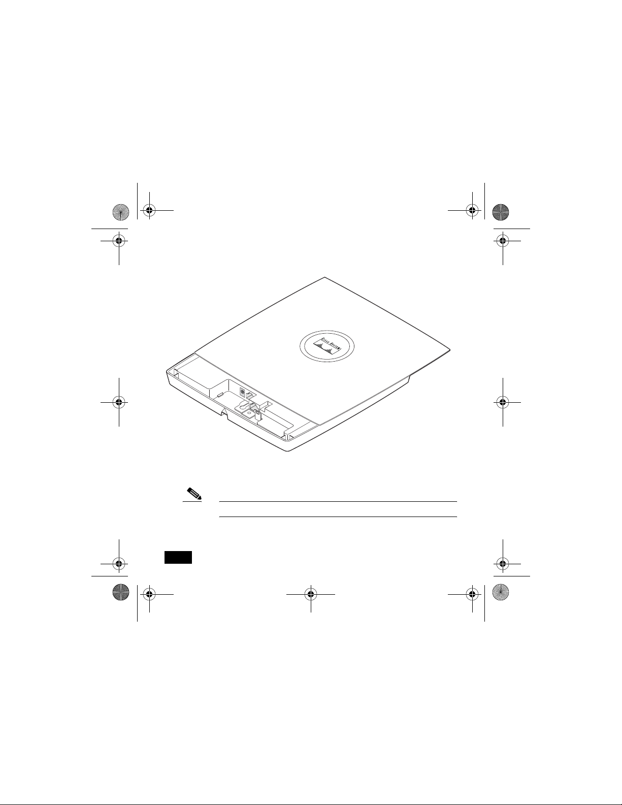
How to Open the Top Cover
The top cover provides access to the cable and power connections.
Caution Do not open the access point top cover as you would a hatch or
door. You could damage the cover by doing so. An instruction
label is attached to the access point. Take time to read the label
before you open the access point cover.
When you have familiarized yourself with the opening procedure, we
recommend that you remove the label, putting it in a safe place, such as inside
the cover of this guide.
Note Status LED indications are not visible when the top cover is open.
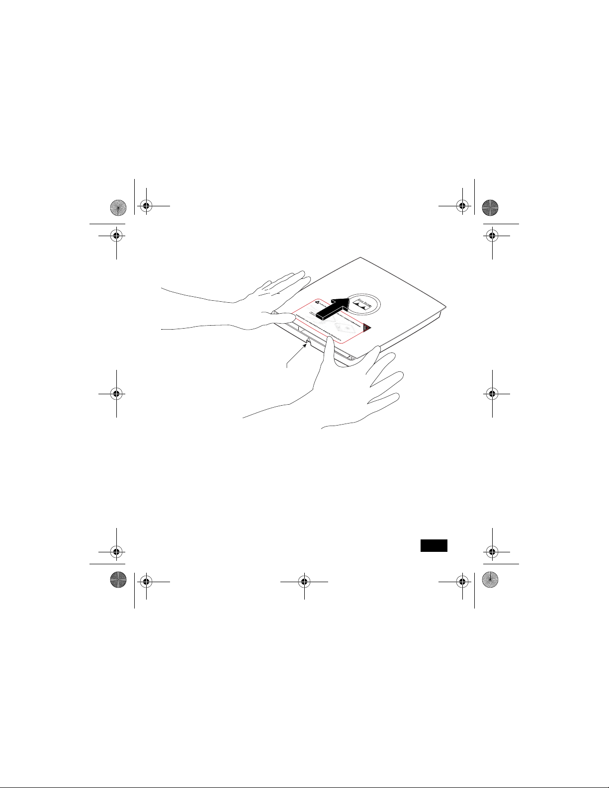
Follow these steps to open the top cover:
1. Put the access point on a flat surface, and grasp it with both hands, as
shown in this illustration.
2
78-18092-01
Page 5
a521qsg.fmb Page 3 Monday, March 12, 2007 10:40 AM
DRAFT - CISCO CONFIDENTIAL
Cable access notch
and arrow
121061
Quick Start Guide Cisco Aironet 521 Access Points
3
Page 6
a521qsg.fmb Page 4 Monday, March 12, 2007 10:40 AM
DRAFT - CISCO CONFIDENTIAL
2. Gently push the cover away from you until it stops, as shown in this
illustration.
3. Remove the opening instruction label from the top cover.
121423
Note We recommend that you save the label for reference.
4
78-18092-01
Page 7
a521qsg.fmb Page 5 Monday, March 12, 2007 10:40 AM
DRAFT - CISCO CONFIDENTIAL
Safety Information
The FCC, with its action in ET Docket 96-8, has adopted a safety standard for
human exposure to RF electromagnetic energy emitted by FCC-certified
equipment. When used with approved Cisco Aironet antennas, Cisco Aironet
products meet the uncontrolled environmental limits found in OET-65 and
ANSI C95.1, 1991. Proper operation of this radio device according to the
instructions in this document and the installation and configuration guide will
result in user exposure substantially below the FCC recommended limits.
• Do not hold any component containing a radio such that the antenna is
very close to or touching any exposed parts of the body, especially the
face or eyes, while transmitting.
• The use of wireless devices in hazardous locations is limited to the
constraints posed by the safety directors of such environments.
Warnings
Warning
Quick Start Guide Cisco Aironet 521 Access Points
This product must be connected to a Power-over-Ethernet
(PoE) IEEE 802.3af compliant power source or an IEC60950
compliant limited power source.
5
Page 8
a521qsg.fmb Page 6 Monday, March 12, 2007 10:40 AM
DRAFT - CISCO CONFIDENTIAL
Warning
Warning
Warning
Warning
6
In order to comply with FCC radio frequency (RF) exposure
limits, antennas should be located a minimum of 7.9 in. (20 cm)
or more from the body of all persons.
Do not operate your wireless network device near unshielded
blasting caps or in an explosive environment unless the
device has been modified to be especially qualified for such
use.
Do not work on the system or connect or disconnect cables
during periods of lightning activity.
Read the installation instructions before you connect the
system to its power source.
78-18092-01
Page 9

a521qsg.fmb Page 7 Monday, March 12, 2007 10:40 AM
DRAFT - CISCO CONFIDENTIAL
Warning
This product relies on the building’s installation for
short-circuit (overcurrent) protection. Ensure that the
protective device is rated not greater than: 20A.
Overview
This guide is designed to help you minimally configure a Cisco Aironet 521
Series Access Point using the access point graphical user interface (GUI)
through your web browser. The GUI is the primary-configuration tool. This
guide provides an overview of the access point and provides instructions for
mounting it.
Do not attempt to connect a cable with a protective boot to the access point
Ethernet or console port. Because of limited space in the connection area,
booted connectors will not fit.
Unpacking the Access Point
Each access point package contains the following items:
• TBD
• Mounting hardware kit - TBD
Quick Start Guide Cisco Aironet 521 Access Points
7
Page 10

a521qsg.fmb Page 8 Monday, March 12, 2007 10:40 AM
DRAFT - CISCO CONFIDENTIAL
• This guide
Complete these steps to prepare for installation.
1. Carefully unpack and remove the access point and hardware kit from the
shipping box.
2. Return all packing material to the shipping container, and save it.
3. Verify all the package contents, and inspect each item for damage. If any
item is missing or damaged, contact your Cisco representative for
support.
4. Become familiar with the access point and its features, which are
identified in this illustration.
Caution Be careful when handling the access point; the bottom plate
might be hot.
8
78-18092-01
Page 11

a521qsg.fmb Page 9 Monday, March 12, 2007 10:40 AM
DRAFT - CISCO CONFIDENTIAL
1
2
3
4
5
6
1 Power connector 5 Padlock post
2 Ethernet port 6 Mode button
3 Keyhole slot 7 Ethernet (E) and Radio (R)
4 Console port 8 Status LED
8
7
LEDs
121541
Quick Start Guide Cisco Aironet 521 Access Points
9
Page 12

a521qsg.fmb Page 10 Monday, March 12, 2007 10:40 AM
DRAFT - CISCO CONFIDENTIAL
Installation Summary
Installing the access point involves these operations:
• Mounting the access point
• Connecting power
• Configuring basic settings
• Configuring security settings
Before you install the access point, make sure that you are using a computer
connected to the same network as the access point, and obtain the following
information from your network system administrator:
• TBD
10
78-18092-01
Page 13

a521qsg.fmb Page 11 Monday, March 12, 2007 10:40 AM
DRAFT - CISCO CONFIDENTIAL
If you are not connected to a DHCP server, you can assign an IP address to
the access point using the CLI. In this situation, obtain a unique IP address
for your access point, a default gateway, and subnet mask from your network
system administrator.
Mounting the Access Point
The access point uses a detachable universal mounting plate to mount the
access point to flat surfaces such as a wall or ceiling. The universal mounting
plate is also used to mount the access point to an electrical or network
junction box, or to the provided rail clips for below a suspended ceiling.
The mounting process is simple and requires common tools. Because it is
detachable, you can use the universal mounting plate to mark the positions of
the mounting holes for your installation. You then install the universal
mounting bracket on the surface and attach the access point when you are
ready.
When you have mounted the access point, its padlock post enables you to
protect the Ethernet, power cables, and Mode button, and to lock the access
point with a padlock.
Quick Start Guide Cisco Aironet 521 Access Points
11
Page 14

a521qsg.fmb Page 12 Monday, March 12, 2007 10:40 AM
DRAFT - CISCO CONFIDENTIAL
Connecting Power
Connect the 521 series access point to a power source. The access point can
be powered locally by using an AC power module or over the Ethernet using
power sourcing equipment (PSE).
When power is supplied to the access point, a routine power-up sequence
begins which you can monitor by observing the access point status LED.
During the power up sequence the LED displays a series of colors. When the
power up sequence is complete, the LED displays a light green color to
indicate that it is ready for operation. When a client associates to the access
point, the status LED changes to blue. The LED displays amber to indicate a
problem, such as when the access point is unable to verify that the PSE is
supplying sufficient power. See the “Configuring Power” section on page 17.
Obtaining an IP Address
Your access point needs an IP address to operate. The access point is no
longer shipped with a default IP address. It obtains an IP address from your
network’s DHCP server when you connect the access point to your network.
If your network does not have a DHCP server, the access point continues to
request an IP address until you assign it one.
12
78-18092-01
Page 15

a521qsg.fmb Page 13 Monday, March 12, 2007 10:40 AM
DRAFT - CISCO CONFIDENTIAL
You must know your access point’s IP address before you can use the
web-based management GUI. If your access point obtained its IP address
from your network’s DHCP server, you or your network administrator can
find it by querying the DHCP server using the access point’s MAC address.
You can also find the access point’s IP address using Cisco’s IP Setup Utility
You can download IPSU from Cisco.com.
Configuring Power
After connecting the access point to a power source, its status LED might be
amber, which can indicate that the access point is unable to verify that the
PSE is supplying sufficient power. In such cases, you will need to configure
settings on the access point or the switch to identify your power source.
Configuring Basic Settings
Follow these steps to configure basic settings for the access point using the
GUI Express Setup page.
Quick Start Guide Cisco Aironet 521 Access Points
13
Page 16

a521qsg.fmb Page 14 Monday, March 12, 2007 10:40 AM
DRAFT - CISCO CONFIDENTIAL
Configuring Security Settings
After you assign basic settings to your access point, you must configure
security settings to prevent unauthorized access to your network. Because it
is a radio device, the access point can communicate beyond the physical
boundaries of your work site.
Understanding Express Security Settings
TBD
Express Security Limitations
TBD
SSID Configuration
TBD
Note These characters are not allowed: ?, “, $, [, \, ], and +. In
addition, these characters cannot be the first character:
!, #, and ;.
14
78-18092-01
Page 17

a521qsg.fmb Page 15 Monday, March 12, 2007 10:40 AM
DRAFT - CISCO CONFIDENTIAL
In Case of Difficulty
If you followed the instructions in previous sections of this guide, you should
have had no trouble getting your access point installed and running. If you do
experience difficulty, the following sections provide basic troubleshooting
information.
Before contacting Cisco, look for a solution to your problem in this guide or
the troubleshooting chapter of the Cisco Aironet 1130AG Series Access Point
Hardware Installation Guide.
The Technical Assistance Center (TAC) maintains a list of top wireless
technology issues on Cisco.com. Follow these steps:
Step 1 Browse to http://www.cisco.com.
Step 2 Click Support. A drop-down window appears. If the drop-down
window appears before you select it, go to step 3.
Step 3 Click Get Tools & Resources. The Tools & Resources page
appears.
Step 4 Choose an appropriate support link.
Quick Start Guide Cisco Aironet 521 Access Points
15
Page 18

a521qsg.fmb Page 16 Monday, March 12, 2007 10:40 AM
DRAFT - CISCO CONFIDENTIAL
Checking the Access Point LEDs
If your access point is not working properly, check the Status LED on the top
panel or the Ethernet and Radio LEDs in the cable bay area. You can use the
LED colors to assess the unit status.
Note To see the Ethernet and Radio LEDs you must open the access
point cover. (Refer to the “How to Open the Top Cover” section
on page 2.)
The LED meanings are in this table.
Top of Unit Cable Bay Area
Status LED Ethernet LED Radio LED
Meaning
16
78-18092-01
Page 19

a521qsg.fmb Page 17 Monday, March 12, 2007 10:40 AM
DRAFT - CISCO CONFIDENTIAL
Top of Unit Cable Bay Area
Status LED Ethernet LED Radio LED
For more details on these LED status codes, see the “Troubleshooting”
chapter of the Cisco Aironet 1130AG Series Access Point Hardware
Installation Guide.
Meaning
Checking Basic Settings
Mismatched basic settings are the most common causes of lost connectivity
with wireless clients. If the access point does not communicate with client
devices, check the following areas.
TBD
Quick Start Guide Cisco Aironet 521 Access Points
17
Page 20

a521qsg.fmb Page 18 Monday, March 12, 2007 10:40 AM
DRAFT - CISCO CONFIDENTIAL
Resetting to Default Configuration
If you forget your password that allows you to configure the access point, you
may need to completely reset the configuration. You can use the MODE
button on the access point to reset the configuration.
Note These steps reset all configuration settings to factory defaults,
including passwords, WEP keys, the IP address, and the SSID.
Using the MODE Button
Follow these steps to delete the current configuration and return all access
point settings to the factory defaults by using the MODE button:
1. Open the access point cover (refer to the “How to Open the Top Cover”
section on page 2).
2. Disconnect power from the access point (the power jack for external
power or the Ethernet cable for in-line power).
3. Press and hold the MODE button while you reconnect power to the
access point.
4. Continue pressing the MODE button until the Ethernet LED turns
amber. (approximately 2 to 3 seconds). Then release the button.
18
78-18092-01
Page 21

a521qsg.fmb Page 19 Monday, March 12, 2007 10:40 AM
DRAFT - CISCO CONFIDENTIAL
5. After the access point reboots, you must reconfigure it using the web
browser interface, the Telnet interface, or the access point console port.
Using the Web Browser Interface
Follow these steps to delete the current configuration and return all access
point settings to factory defaults using the web browser interface:
TBD
Compliance Information
This equipment has been tested and found to comply with the European
Telecommunications Standard ETS 300.328. This standard covers Wideband
Data Transmission Systems referred to in CEPT recommendation T/R 10.01.
This type-accepted equipment is designed to provide reasonable protection
against harmful interference when the equipment is operated in a commercial
environment. This equipment generates, uses, and can radiate radio
frequency energy and, if not installed in accordance with the instruction
manual, may cause harmful interference to radio communications.
Quick Start Guide Cisco Aironet 521 Access Points
19
Page 22

a521qsg.fmb Page 20 Monday, March 12, 2007 10:40 AM
DRAFT - CISCO CONFIDENTIAL
The Declarations of Compliance for this product relevant to the European
Union and other countries following EU Directive 1999/5/EC (R&TTE
Directive) can be found in the Cisco Aironet 1130AG Series Access Point
Hardware Installation Guide. This guide is available on Cisco.com.
Cisco 90-Day Limited Hardware Warranty
Terms
There are special terms applicable to your hardware warranty and
various services that you can use during the warranty period. Your
formal Warranty Statement, including the warranties and license
agreements applicable to Cisco software, is available on Cisco.com.
Follow these steps to access and download the Cisco Information
Packet and your warranty and license agreements from Cisco.com.
1. Launch your browser, and go to this URL:
http://www.cisco.com/univercd/cc/td/doc/es_inpck/cetrans.htm
The Warranties and License Agreements page appears.
2. To read the Cisco Information Packet, follow these steps:
a. Click the Information Packet Number field, and make sure that
the part number 78-5235-03B0 is highlighted.
b. Select the language in which you would like to read the document.
20
78-18092-01
Page 23

a521qsg.fmb Page 21 Monday, March 12, 2007 10:40 AM
DRAFT - CISCO CONFIDENTIAL
c. Click Go.
The Cisco Limited Warranty and Software License page from the
Information Packet appears.
d. Read the document online, or click the PDF icon to download and
print the document in Adobe Portable Document Format (PDF).
Note You must have Adobe Acrobat Reader to view and print
PDF files. You can download the reader from Adobe’s
website: http://www.adobe.com
3. To read translated and localized warranty information about your
product, follow these steps:
a. Enter this part number in the Warranty Document Number field:
78-5236-01C0
b. Select the language in which you would like to read the document.
c. Click Go.
The Cisco warranty page appears.
d. Review the document online, or click the PDF icon to download
and print the document in Adobe Portable Document Format (PDF).
You can also contact the Cisco service and support website for assistance:
Quick Start Guide Cisco Aironet 521 Access Points
21
Page 24

a521qsg.fmb Page 22 Monday, March 12, 2007 10:40 AM
DRAFT - CISCO CONFIDENTIAL
http://www.cisco.com/public/Support_root.shtml.
Duration of Hardware Warranty
Ninety (90) days.
Replacement, Repair, or Refund Policy for Hardware
Cisco or its service center will use commercially reasonable efforts to ship a
replacement part within ten (10) working days after receipt of a Return
Materials Authorization (RMA) request. Actual delivery times can vary,
depending on the customer location.
Cisco reserves the right to refund the purchase price as its exclusive warranty
remedy.
To Receive a Return Materials Authorization (RMA) Number
Contact the company from whom you purchased the product. If you
purchased the product directly from Cisco, contact your Cisco Sales and
Service Representative.
Complete the information below, and keep it for reference:
Company product purchased from
Company telephone number
Product model number
22
78-18092-01
Page 25

a521qsg.fmb Page 23 Monday, March 12, 2007 10:40 AM
DRAFT - CISCO CONFIDENTIAL
Product serial number
Maintenance contract number
Quick Start Guide Cisco Aironet 521 Access Points
23
Page 26

a521qsg.fmb Page 24 Monday, March 12, 2007 10:40 AM
USA-Federal Communications Commission (FCC)
Any changes or modifications not expressly approved by the party responsible for
compliance could void the user’s authority to operate the equipment.
This equipment has been tested and found to comply with the limits for a Class B
digital device, pursuant to Part 15 of FCC Rules. These limits are designed to
provide reasonable protection against harmful interference in a residential
installation. This equipment generates, uses, and can radiate radio frequency
energy. If not installed and used in accordance with the instructions, it may cause
harmful interference to radio communications. However, there is no guarantee
that interference will not occur in a particular installation.
If this equipment does cause harmful interference to radio or television reception,
which can be determined by tuning the equipment off and on, the user is
encouraged to try and correct the interference by one or more of the following
measures:
-Reorient or relocate the receiving antenna
-Increase the distance between the equipment and the receiver.
-Connect the equipment to outlet on a circuit different from that to which the
receiver is connected.
-Consult the dealer or an experienced radio/TV technician for help.
DRAFT - CISCO CONFIDENTIAL
24
78-18092-01
 Loading...