

Page 1

CISCO CONFIDENTIAL - Draft 1
CHA PT ER
1
Overview
The Cisco Aironet 1520 Ser ies Outdoo r Mesh Acc ess Point (h ereaft er cal led the acce ss po int) is a
wireless device designed for wireless client access, point-to-point bridging, point-to-multipoint
bridging, and point-to-multipoint mesh wireless connectivity. The access point is a standalone unit that
can be mounted on a streetlight pole or on a building wall or overhang. It is a self-contained outdoor unit
that can be configured with a wire d backhau l connec tion to an Et hernet segment for a ro oftop
deployment or can be configured with a w ire less ba ckha ul for a pole -top de ployme nt. The a cce ss point
can be installed whe re p ower is available wit hout the nee d f or a w ire d ne twork conne ct ion.
The access po int i s available in two mode ls : L AP1522 (s uppo rts 2.4 -G Hz an d 5-G Hz ra dio s) a nd
LAP1521 (supports a 2.4 -G Hz radio) .T he a cce ss poi nt p rovides cli ent ac cess an d wi reles s m esh
backhaul that suppo rts 6 to 54 Mbps dat a rates with out the need for a lice nse. The LA P1522 mo del
dedicates the 5-GHz radio for backhaul operations to reach a wired network and uses the 2.4-GHz radio
for wireless client s. T he L A P1521 m ode l u ses the 2 .4- o r 5 -GH z ra dio fo r bot h back ha ul and w ire less
clients.
The access point can also operate as a relay node for other access points not directly connected to a wired
network. Intelligent wireless r outing is p rovid ed b y the paten t-pending Ad apti v e Wireless Path Proto col
(AWPP). This enables each access point to identify its neighbors and intelligently choose the optimal
path to the wired netw ork b y ca lcula ting the c ost of e ach pa th in ter ms of signal str ength and the n umber
of hops required to g et to a c ont roll er.
OL-12632-01
The access point is configured, monitored, and operated through a Cisco wireless LAN controller
(hereafter ca lled a controller) as described in the Cisco Wireless LAN Controller Configuration Guide.
The Deployment Guide: Ci sco Mesh Netw orki ng Solu tion describes how to plan and initially configure
the Cisco Mesh network, which suppor ts wireless poin t-to-p oint, point- to-mult ipoint, and me sh
deployments. The controllers use a browser-based management system, a command-line interface (CLI),
or the Cisco Wireless Control System (WCS) network management system to manage the controller and
the associated access points. The access point is compliant with Wi-Fi Protected Access (WPA2) and
employs hardware-base d Advanced E ncryp tion Sta nda rd ( AE S) en crypt ion b etw een w ire less nodes t o
provide end-to-end se cu rity.
This chapter provides information on the following topics:
• Main Hardware Feature s, page 2
• Network Configuration Examp les, page 6
Cisco Aironet 1520 Series Outdoor Mesh Access Point Hardware Installation Guide
1-1
Page 2

Main Hardware Features
Some of the access point’s main hardware features are listed below:
• One or two radios (2.4- and 5-GHz)— see the “Single or D ual Radio Op erati on” sect ion on page 3
• External radio an ten nas — see the “Ext erna l A nte nna s” se ct ion o n pa ge 3
• Multiple power sources—see the “Mu ltiple Power Sources” sec tion on page 4
• Rugged metal enclosure—see the “Metal Enclosure” section on page 5
• Optional Ethernet ports— see the “Ethe rnet Ports” sect ion on page 5
• Optional cable modem—see the
• Optional hardware—see the “Option al Hard ware” sec tion on page 6
–
Cable strand mount kit
–
Pole mount kit
–
150 ft (45.72 m) Etherne t outdoor cable
• Optional battery backup—future availability
Figure 1 shows the access point connectors .
Figure 1 Access Point Connectors
14
25
36
Overview
2
OL-12632-01
Page 3

Connectors
The optional featues of the access point support these connectors (see Figure 1):
• Ethernet (PoE) uplink con nector —(typ e RJ45 wi th T BD for wa terp roo fing)
• Ethernet downlink connect or—(t ype RJ45 wi th TBD for wate rproo fing)
• Three Type N antenna connectors (2.4-GHz radio)
• One Type N antenna connector (5-GHz radio)
• Fiber-optic connector— Sma ll form factor pluggable (SFP)
• Power-over-cable (POC) connector—(TBD)
• AC power connector
Single or Dual Radio Operation
The access po int i s available in two mode ls : L AP1522 (s uppo rts 2.4 -G Hz an d 5-G Hz ra dio s) a nd
LAP1521 (supports a 2.4- or 5-GHz radio). The radios use external antennas (see “External Antennas”).
The LAP1522 model supports simultaneous dual-radio operation using a 2.4-GHz 802.11b/g radio and
a 5-GHz 802.11a ra dio. The LAP1 521 mode l su ppor ts b ot h me sh b ackh aul op erat ion and w ireless
clients using a single 2.4- or 5-G Hz radio.
The 5-GHz rad io i ncor por ate s a n Unl ice nsed N ationa l I nf orm ati on I nfr ast ruc ture ( UNI I) radi o
transceiver operating in the UNII 5-GHz frequency bands. The 5-GHz radio on the access point is used
for backhaul oper ations to the contro ller. The 5-GHz radio can also opera te in the 4. 9-GHz Public
Safety band in the United States.
Note The 4.9-GHz band requires a license and may be used only by qualif ied Publ ic Safety operators
as defined in section 90.20 of t he FC C rule s.
The 2.4-GHz radio supports three antennas for multi-input, single output (MISO) operation. The radio
uses three receivers to support maximum ratio combining (MRC) to enhance receiver performance.
MRC is a technique that combines the signals from multiple receivers in a manner to optimize the
signals. MRC can provide up to 3 dB of incr ease d receive signal strengt h.
The access poin t do es no t sup por t both ra dio s c onfigured f or bac kha ul supp ort
External Antennas
The access point is equ ipped with t hree N-ty pe radi o freque ncy (RF) conne ctor on the t op of the uni t
for external 2.4-GHz antennas to support multiple input single output (MISO) operation. The LAP1522
model also has one to three N-type RF connectors on the bott om of the unit for external 5 -GHz antennas
(see Figure 1). Whe n usi ng t he o pti onal Cisco co mpa ct om ni dir ectiona l a nten nas, the 2. 4- a nd 5-GHz
antennas conn ect dir ectl y to t he a cce ss point. T he Ci sco omn idi rect ion al an tenn as use ver tic al
polarization.
The access point can also be e quipped with spec ific third-pa rty external ant ennas (see Table 1 and
Table 2), subject to local regulatory requirements. When you are installing third-party antennas, they
must be installed with all waterproofing steps recommended by the third-party manufacturer.
Note When you mount the access point in an indoor environ ment, y ou mus t also mount the antennas
in an indoor environment.
Warning
Only trained and qualified personnel should be allowed to install, replace, or service
this equipment.
Statement 1030
Page 4
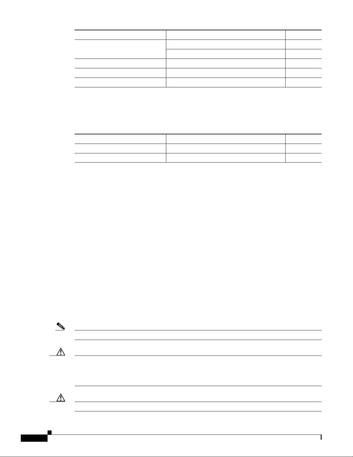
Table 1 and Table 2 lists the supported external antennas for the access point.
Table 1 External 5-GHz Antennas
Part Number Model Gain (dBi)
AIR-ANT5180V-N 5-GHz compact omnidirectional
4.9-GHz compact omnidir ectiona l
1
2
8
7
AIR-ANT58G10SSA-N 5-GHz sector 9.5
AIR-ANT5114P-N 4.9- to 5-GHz patch
AIR-ANT5117S-N 4.9- to 5-GHz 90-degree sector
1. The compact omnidirectional antennas mount directly on the access point.
2. The use of the 4.9-GHz band requires a license and may be used only by qualified Public Safety operators as defined in
section 90.20 of the FCC rules.
Table 2 External 2.4-GHz Antennas
2
2
14.0
17.0
Part Number Model Gain (dBi)
AIR-ANT2450V-N 2.4-GHz compact omnidirec tional
1
5.5
AIR-ANT2480V-N 2.4 GHz omnidirectiona l 8.0
1. The compact omnidirectional antennas mount directly on the access point.
Multiple Power Sources
The access point supports these power sources:
• Power-over-Ethernet (POE)—1520 power injecto r
• AC power—90 to 480 VAC
• Quazi-AC power-over-cable (POC)—40 to 90 V
• External 12 VDC
• Internal battery
The access point can be connected to more than one power source. The access point detects the
available input sources and switches to the preferred power source using the following default
prioitization:
• AC power or POC power
• External 12VDC power
• 1250 Power Injetor PoE power
• Internal Battery power
Note The power source default prioriti zation can be us er reconf i gu red.
Caution To provide inline PoE, you must use the 1250 power injector. Other power injectors, PoE
switches, and 802.3af power sources cannot provide adequate power , which may cause the
access point to malfunct ion and ca use over-current condi tions at the power source. You
must ensure that the switch port connected to the access point has PoE turned off.
Caution The power injector and the power module must be used in an indoor environme nt only.
Overview
4
OL-12632-01
Page 5

Caution When the access point is installed outdoors or in a wet or damp location, the AC branch
Ethernet Ports
circuit that is powering the access point should be provided with ground fault protection
(GFCI), as required by Article 210 of the National Electrical Code (NEC).
The AC power cord options are listed below:
• 40-ft (12.2-m) power cord for light pole installations in the US and Canada.
• 40-ft (12.2-m) power c ord f or use o uts ide the US an d C an ada. One e nd of t he power cor d is
terminated with an access point AC power connector and the other end is unterminated.
• 4-ft (1.2-m) streetlight power tap adapter for light pole installations in the US and Canada.
The access po int sup por ts an Et hern et upl ink po rt a nd a d ownlink por t. T he a cce ss poi nt’s Ethernet
uplink port uses an RJ-45 connector (with weatherproofing) to link the access point to your10BASE-T,
100BASE-T , or 1000BASE-T network. The Ethernet cable is used to send and receive Ethernet data and
to optionally supply inline 56-VDC power from the power injector.
The access point’s downlink Ethernet p ort u ses an R J -45 conne c tor ( with we ath erpr oofing) t o pr ovide
LAN connectivity and IEEE 802.3af po wer to a peripheral customer device, such as a camera or sensor
gateway.
The Ethernet MAC addresses are printed on the label on the side of the access point (refer to the
“Finding the Product Serial Number - TBD” section on page 13).
Tip s The ac c ess po in t s e nse s th e Et hern et an d p ower si gn als an d au to ma tic al ly sw it ch es
internal circuitry to match the cable connections.
Caution To provide inline PoE , you must use the 1520 power injector. Other power injectors, PoE
switches, and 802.3af power sources can no t provide adequa te power, which may cause
the access point to malfunction and cause possible over-current conditions at the power
source.
Metal Enclosure
The access po int uses a me tal en cl osure th at ca n acco mm oda te bo th in door or o utdoo r ope rat ing
environments and a n in dust r ial te mp er atur e op er ati ng range of (–40°F (–40°C ) to 131°F (5 5°C). The
access point complies with NEMA Type 4X and I P66 re quir emen ts fr om IEC6 052 9.
Note When the access point is mounted indoors, the antennas must also be mounted indoors.
Cable Modem
Page 6

Optional Hardware
Some of the access point hardware options are listed below:
• Cable modem—DOCSIS 2.0 compatible for direct connection to cable lines.
• Fiber optic module—uses Small Form Factor Pluggable (SFP) connections for connection to fiber
optic lines.
–
Supports 100BaseBX module s
–
Supports 15.5 mi (25 km) of fiber-optic cable.
• Pole mount kit (SKU - TBD)—provides hardware for mounting the access point to the top of a
metal or wood pole, such as a streetlight pole.
• Streetlight power tap adapter (SKU - TBD)—connects to the light control connector on a streetlight
pole and provides AC power to the access point.
• Outdoor ra ted Ethernet cable ( ???)—used to supply Ethernet and optional DC power to the access
point.
• 1520 power injector (SKU - TBD)—provides power-over-Ethernet (PoE) to the access point.
• AC power cord (for additional information, refer to the “Multiple Power Sources” section on
page 4).
• Future availability—battery backup module (80 Watt hour (WHr). The integrated battery can be
used to power the uni t w hen extern al power so ur ces a re not available.
–
Four hour access po int op erat ion u sin g two r adio s at 77oF (25oC)—with PoE outpu t port o ff
–
Two hour access point operation using two radi os at 77oF (25oC)— with PoE output port on
–
User installable and replaceable
•
Network Configuration Examples
The access poin t is a wir eless d evice desi gned fo r wir eless c lien t a cce ss and po int -to-p oint bri dgin g,
point-to-multipoint bridging, and point-t o-multi point mesh w ireless conne ctivity. The access point
provides 5-GHz back ha ul c apab ilit y to li nk wi th a not her ac cess point to r eac h a wir ed ne twork
—connection or to p rovide repe ate r ope rat ions for oth er a cce ss poi nts.
The access point plays two primary radio roles: a root access point (hereafter called a RAP) or a
non-root access poi nt (here after called a MAP). When the ac cess p oint ha s a wi red E thern et connec tion
to the controll er (thr oug h a s witc h), t he ra dio role is ca ll ed a RAP. A RAP is a parent node t o any
bridging or mesh network. A controller can support one or more RAPs, each one parenting the same or
different wireless networks. The re can be more than one RAP for the same mesh networ k for
redundancy. RAPs also support wireless clients on the band not being used for the backh aul interfac e.
When the access point does not have a wired Ethernet connection to the controller (through a switch),
the radio role is called a MAP. The M APs have a wireless connection (through the backhaul interface)
to other MAPs and final ly to a RA P wit h an Eth erne t c onn ect ion thro ugh a swit ch t o the c ontro ller.
MAPs may also have a wired Ethernet connection to a local LAN and serve as a bridge endpoint for that
LAN (using a poi nt-to- poin t or po i nt-to- mult ipoin t brid ge c onn ecti on) . MA Ps also sup port wi reless
clients on the band not used for the backhau l interfac e.
Overview
6
OL-12632-01
Page 7
Wireless Backhaul
The access po int sup por ts wi reless ba ckha ul c apa bil ity usin g th e 5-GH z radi o t o brid ge to an othe r
access point to re ach a wi red n etwo rk co nnec tio n to a cont rol ler (s ee Fi gu re 2). The acce ss po int
connected to the wired network is considered a RAP in this configuration. The remote access point is
considered a MAP and transfers wireless client traffic to the RAP for transfer to the wired network.
Lightweight access point protocol (LWAPP) control traffic is also transferred over this bridged link.
Note The LAP 1505 model uses the 2.4-GHz radio for backhaul and wir eless client operat ions.
Figure 2 Access Point Backhaul Example
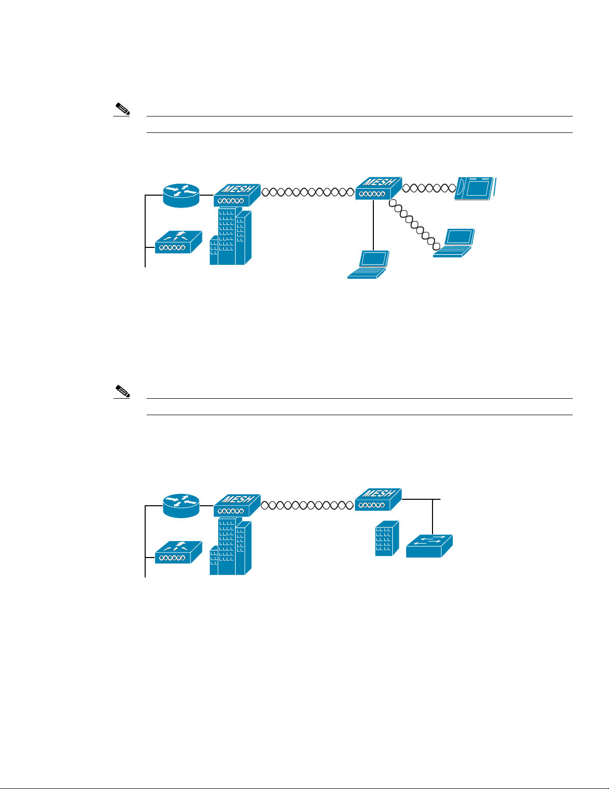
Point-to-Point Bridging
The access points can be used to extend a remote network by using the 5-GHz backhaul radio to bridge
the two network segments as sho wn in Figure 3. To support Ethernet bridging, you must enable bridging
on the controller for each access point .
Note The LAP 1505 model uses the 2.4-GHz radio for bridgi ng op er ations .
Wireless client access is sup por ted; however, if bridging between tall building s, the 2.4- Gh z w irele ss
coverage area may be limited and possib ly not suitabl e for direc t wireless cli ent access.
(5.8 Ghz)
(2.4 Ghz)
148438
Figure 3 Access Point Point-to-Point Bridging Example
148440
Page 8
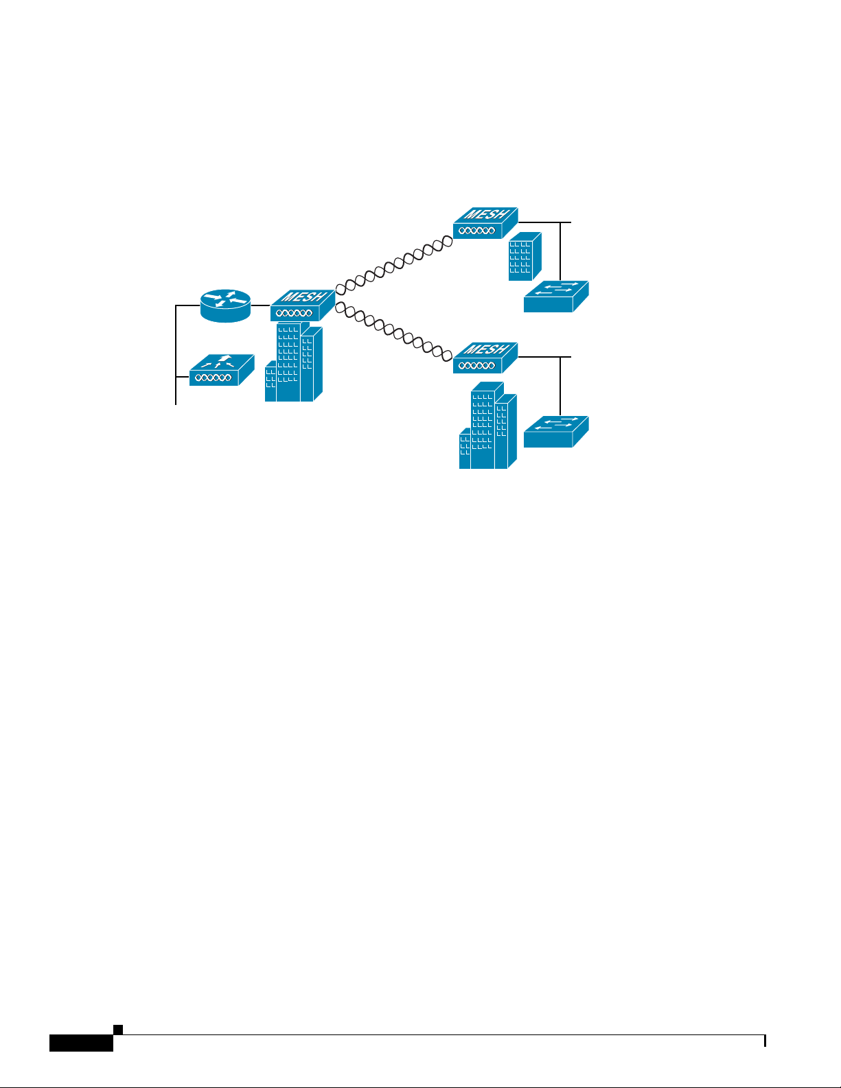
Point-to-Multipoint Bridging
The access points can be used as a RAP to connect multiple remote MAPs with their associated wired
networks (see Figure 4). By default this capability is turned-off for all access points. To support
Ethernet bridging, you mu st enable br idging on the controller for each acc ess point.
Wireless client access can be provided over the bridging link; however, if bridging between tall
buildings, the 2.4-Ghz wi reless c overage area may be l imit ed a nd possi bly not s uitabl e f or dir ect
wireless client access.
Figure 4 Access Point Point to Multipoint Bridging Example
Mesh Network
148439
The access po int s are typ i cal ly d ep loyed in a m esh n etwor k co nfigurati on. I n a typi cal me sh
deployment, one or more RAPs have a wired network connection through a switch to a controller . Other
remote MAPs without w ire d net work c onnec tions us e t he ba ckha ul f eat ure t o o ptima lly link t o a RA P
that is connected to the wired network. In the mesh network, the links between the access points are
referred to as the backhaul links.
Intelligent wireless routing is provided b y the patent-pendin g Adaptiv e W ireless Pa th protocol (AWPP).
This enables each MAP to i dent ify its neig hbor s an d i nte llig ently c hoose t he op timal pa th t o t he RA P
with the wired net work c onn ect ion by ca lcu lat ing the c ost of each pa th i n ter ms o f sign al st reng th an d
the number of hops required to get to a cont roller.
Overview
8
OL-12632-01
Page 9

Figure 5 illustrates a typical mesh configuration using MAPs and RAPs.
Figure 5 Typical Mesh Configuration Using Access Points
IP
155631
Page 10

Layer 2 and Layer 3 Network Operation
The access points support Laye r 2 or Laye r 3 networ k opera ti on. In Lay er 2 configurat ion s, the ac c ess
1
point and the controller are on the same subnet and communicate with encapsulated Ethernet frames
using MAC addresses rather than IP addresses. Layer 2 configurations are typically not scalable into
larger networks. Ad ditio nally, Layer 2 operation is supported o n ly by the Cisco 4400 series controllers.
Access points and cont rol lers in La yer 3 c onfiguration s use IP ad dresse s and U DP pa c kets, whic h c an
be routed through l arge netwo rks. L aye r 3 o pera tio n is sca lab le an d re comm end ed by Cisc o.
Figure 6 illustr ates a ty pi cal L ay er-3 wirel ess ne twor k con figurati on co nt ain ing a ccess poi nts an d a
controller.
Figure 6 Typical Layer 3 Access Point Network Configuration Example
LWAPP
LWAPP
58085
Overview
10
OL-12632-01
Page 11

Figure 7 illustr ates a ty pica l L ayer 2 net work con figurati on. I n a La yer 2 c onfigurat ion, the con troll er
and the access points are on the same subnet.
1
Figure 7 Typical Layer 2 Access Point Network Configuration Example
LWAPP
LWAPP
58084
Page 12

12
Overview
OL-12632-01
Page 13

CISCO CONFIDENTIAL - Draft 1
APPENDIX
B
Declarations of Conformity and
Regulatory Information
This appendix p rovide s decl ara tio ns of co nfo rm ity a nd regul at ory inf orm ati on f or the
Cisco Aironet 1520 ser ies lig htwei gh t ou tdoor m esh a cce ss poi nt.
This appendix cont ai ns the fo llowing sec tio ns:
• Manufacturers Federal Commu nication Com mission Decl aration of Conf ormit y Statemen t, page 2
• Department of Comm uni ca tions— Cana da , pa ge 3
• Declaration of Conformity for RF Exposure, page 3
• Administrative Rules for Cisco Aironet Access Points in Taiwan, page 4
OL-12632-01
Cisco Aironet 1520 Series Outdoor Mesh Access Point Hardware Installation Guide
B-1
Page 14

Manufacturers Federal Communication Commission
Declaration of Conformity Statement
s
Tested T o Comply
With FCC Standard
FOR HOME OR OFFICE USE
Model:
AIR-LAP1522AG-A-K9
AIR-LAP1521G-A-K9
FCC Certification number:
AIR-RM1520G-A-K 9: LDK102064
AIR-RM1520A-A-K 9: LDK102063
Manufacturer:
Cisco Systems, Inc.
170 West Tasman Drive
San Jose, CA 95134- 170 6
USA
This device complies with Pa rt 15 rules. Operation is subject to the following two conditions:
1. This device may not ca use h ar mf ul i nte rf er ence , an d
2. This devi ce must accept an y inte rferen ce recei v ed, includin g interf erence that may ca use und esired
operation.
This equipment has been tested and found to comply with the limits of a Class B digital de vice, pursuant
to Part 15 of th e FCC Rules. These limi ts are d esigned t o prov ide reaso nable pr otecti on agai nst ha rmful
interference whe n the equi pmen t is opera ted in a resi dential environment. This eq uipm ent gene rates,
uses, and radiat es r a dio f req uency en ergy, and if not ins tall ed a nd used i n ac co rdanc e w ith the
instructions, may cause harmful interference. However, there is no guarantee that interference will not
occur. If this equipment does cause interference to radio or television reception, which can be
determined by turnin g the equi pment off and on, th e user is enc ourag ed to co rrect the interf ere nce by
one of the following measures:
• Reorient or re loca te the r ece iving an tenn a.
• Increase separation between the equipment and receiver.
• Connect the equipment to an outlet on a circuit different from which the receiver is connected.
• Consult the dea ler o r an experi enc ed radi o/T V t ech ni cia n.
Caution The Part 15 radio device operates on a non-interference basis with other devices operating
at this frequency when using Cisco-supplied antennas. Any changes or modification to the
product not express ly a pproved by Cisc o co ul d void th e user’s authority to o per ate th is
device.
Caution To meet regulatory restrictions, the access point must be professionally installed.
2
OL-12632-01
Page 15

Note The use of the 4.9-GHz band requires a license and may be used only by qualified Public Safety
operators as defined in section 90.20 o f the FCC r ules ( LAP151 0 model onl y).
VCCI Statement for Japan
Warning
This is a Class B product based on the standard of the Voluntary Control Council for Interference from
Information Technology Equipment (VCCI). If this is used near a radio or television receiver in a
domestic environment, it may cause radio interference. Install and use the equipment according to
the instruction manual.
Department of Communications—Canada
IC Certification Number:
AIR-RM1520G-A-K 9: 2461B-102064
AIR-RM1520A-A-K 9: 2461B-102063
Canadian Compliance Statement
This Class B Digital apparatus meets all the requirements of the Canadian Interference-Causing
Equipment Regulations.
Cet appareil numerique de la classe B respecte les exigences du Reglement sur le material broilleur du
Canada.
This device complies with Class B Limits of Industry Canada. Operation is subject to the following two
conditions:
1. This device may not ca use h ar mf ul i nte rf er ence , an d
2. This devi ce must accept an y inte rferen ce recei v ed, includin g interf erence that may ca use und esired
operation.
Cisco’s access points are certified to the requirements of RSS-210 issue 5, RSP 100, and RSS 102 for
spread spectrum devices.
Declaration of Conformity for RF Exposure
This access point product has been fo und to be comp liant to the re quirem ents set forth in CFR 47
Section 1.1307 addressing RF Exp osure from ra dio freq uency devices as defined in Evaluating
Compliance with FCC Guidelines for Human Exposure to Radio Frequency Electromagnetic Fields.T
he antennas should be positioned more than 6.56 feet (2 me ters) from you r body or nearby persons .
This access point is also compliant to EN 50835 for RF exposure.
Page 16

Administrative Rules for Cisco Aironet Access Points in Taiwan
This section provides administrative rules for operating Cisco Aironet access points in Taiwan. The
rules are provide d in bo th Chi nese an d Eng lish .
Chinese Translation
4
OL-12632-01
Page 17

English Translation
Administrative Rules for Low-power Radio-Frequency Devices
Article 12
For those low-power radio-frequency devices that have already rece ived a type-approval, companies,
business units or user s sh ould not ch an ge i ts f reque nci es , in crea se its power o r cha ng e i ts or igi nal
features and functions.
Article 14
The operation of the low-power radio-f requency devices is sub ject to the co nditi ons that no harmful
interference is caused to aviation safety and authorized radio station; and if interference is caused, the
user must stop operating the de vice im mediate ly and can 't re-ope rate it until the h armful int erference is
clear.
The authorized radi o station me ans a radio-c ommu nicat ion servic e operat ing in acco rdanc e with th e
Communication Act.
The operation of the low-power radio-f requency devices is sub ject to th e interfe rence caused by the
operation of an authorized radio station, by another intentional or unintentional radiator, by industrial,
scientific and medi cal (ISM ) eq uipme nt, o r by an i ncid enta l r ad iator.
Page 18

6
OL-12632-01
Page 19

CISCO CONFIDENTIAL - Draft 1
CHA PT ER
7
Cisco Aironet 1520 Series Mesh Access Points
This chapter li sts t h e 152 0 se r ies mesh ac cess poi nt IEEE 8 02. 11b/ g ( 2.4-G Hz) a nd I EE E 802 .11 a
(5-GHz) channel s and t he m ax imum p ower levels supporte d by th e world ’s regulatory domains. For
additional product ha rdware in format ion refe r to the Cisco Aironet 1520 Se rie s Outdoor Me sh Acce ss
Point Hardware Installation Guide.
The AIR-LAP1522 access point model supports both 802.11b/g and 802.11a radios, The AIR-LAP1521
access point mode l on ly su ppo rts a 802 .11 b/g ra dio.
The following topics are covered in this chapter:
• Channels and Maximum Power Levels, page 7-2
• Special Country Restric tions, p age 7-5
• Special Country Restric tions, p age 7-5
OL-xxxxx-01
Channels and Maximum Power Settings for Cisco Aironet Lightweight Access Points
7-1
Page 20

Channels and Maximum Power Levels
CISCO CONFIDENTIAL - Draft 1
Channels and Maximum Power Levels
IEEE 802.11b/g (2.4-GHz Band)
When shipped from the fa ctor y, theAIR-LAP152 2G a cce ss p oint s supp ort the ch an nel s a nd ma xim um
power leve ls listed in Table 7-1 for their regulatory domain.
Note In Table 7-1, the operating data rates (in Mbps) are shown in the CCK and OFDM table cells. For
example: CCK 1-11 indicates CCK data rates of 1 to 11 Mbps and All indicates all CCK and OFDM data
rates.
Table 7-1 Channels and Maximum Conducted Power for the 802.11b/g Radio with Up to
5.5-dBi Antennas
Maximum Conducted Power
Levels (dBm) in the Regulatory
Domains
Center
Channel
ID
12412282525
22417282626
32422282726
42427282726
52432282726
62437282726
72442282726
82447282726
92452282726
10 2457 28 26 26
11 2462 28 25 25
12 2467 – – –
13 2472 – – –
14 2484 – – –
Freq
(MHz)
CCK
1-11
–A
OFDM
6-48
OFDM
Chapter 7 Cisco Aironet 1520 Series Mesh Access Points
54
7-2
Channels and Maximum Power Settings for Cisco Aironet Lightweight Access Points
OL-xxxxx-01
Page 21

Chapter 7 Cisco Aironet 1520 Series Mesh Access Points
CISCO CONFIDENTIAL - Draft 1
Table 7-2 Channels and Maximum Conducted Power for the 802.11b/g Radio with Up to
8.0-dBi Antennas
Center
Channel
ID
12412282424
22417282525
32422282626
42427282726
52432282726
62437282726
72442282726
82447282726
92452282626
10 2457 28 25 25
11 2462 28 24 24
12 2467 – – –
13 2472 – – –
14 2484 – – –
Freq
(MHz)
Maximum Conducted Power
Levels (dBm) in the Regulatory
Domains
–A
CCK
1-11
OFDM
6-48
OFDM
54
Channels and Maximum Power Levels
OL-xxxxx-01
Channels and Maximum Power Settings for Cisco Aironet Lightweight Access Points
7-3
Page 22

Chapter 7 Cisco Aironet 1520 Series Mesh Access Points
Channels and Maximum Power Levels
CISCO CONFIDENTIAL - Draft 1
IEEE 802.11a (5-GHz Band)
When shipped from the factory, the AIR-LAP1522AG access points support the channels and maximum
power leve ls listed in Table 7-4 for their regulatory domain.
Note In Table 7-4, the operating data rate s (in Mbps ) are sho wn in the OFDM ta ble cells. F or example: OFDM
6-36 indicates 6 to 36 Mbps data rates.
Table 7-3 Channels and Maximum Conducted Power for IEEE 802.11a Radio with Up to 17 dBi Antennas
Maximum Conducted Power Levels (dBm) in the Regulatory Domains
Center
Channel
ID
20 4950 20 20 20 20 ––––––
21 4955 20 20 20 20 ––––––
22 4960 20 20 20 20 ––––––
23 4965 20 20 20 20 ––––––
24 4970 20 20 20 20 ––––––
25 5975 20 20 20 20 ––––––
26 4980 20 20 20 20 ––––––
149 5745 20 28 27 26 28 27 26 28 27 26
153 5765 20 28 27 26 28 27 26 28 27 26
157 5785 20 28 27 26 28 27 26 28 27 26
161 5805 20 28 27 26 28 27 26 28 27 26
165 5825 20 28 27 26 28 27 26 28 27 26
Frequency
(MHz)
Bandwidth
(MHz)
OFDM
6-36
–A –N –T
OFDM
(4900 to 5100 MHz)
OFDM
48
5725 to 5850 MHz
54
OFDM
6-36
OFDM
48
OFDM
54
OFDM
6-36
OFDM
48
OFDM
54
7-4
Channels and Maximum Power Settings for Cisco Aironet Lightweight Access Points
OL-xxxxx-01
Page 23

Chapter 7 Cisco Aironet 1520 Series Mesh Access Points
CISCO CONFIDENTIAL - Draft 1
Special Country Restrictions
Table 7-4 lists special restrictions for wireless operation in some countries.
Table 7-4 Special Country Restrictions for Wireless Operation
Channels and Maximum Power Levels
Country
Frequency
Band (GHz)
Regulatory
Domain Special Limitation and Restrictions
Australia 5 –N 5 GHz maximum antenna gain limited to 7 dBi.
Mexico 2.4 –N End user must limit 2.4 GHz operation to 2450 to 2483.5 MHz and 36
dBm EIRP
1
.
New Zealand 5 –N 5 GHz maximum antenna gain limited to 7 dBi.
United States 4.9 –A The use of the 4.9-GHz band requires a lice nse and may be used only
by qualified Public Safety operators as defined in section 90.20 of the
FCC rul e s.
1. EIRP (dBm) = maximum output power (dBm) + antenna gain (dBi)
OL-xxxxx-01
Channels and Maximum Power Settings for Cisco Aironet Lightweight Access Points
7-5
Page 24

Chapter 7 Cisco Aironet 1520 Series Mesh Access Points
Changing the Lightweight Access Point Output Power
CISCO CONFIDENTIAL - Draft 1
Changing the Lightweight Access Point Output Power
This section provides instructions for changing the 1500 series access point output po wer to comply with
the maximum power limits imposed by special regulatory and coun try restrict ions (see the “S p ec i al
Country Restrictions” section on page 7-5). Follow these instructions to change the output power
settings using a co ntroll er an d y our browser:
Note Administrator privileges may be required in order to change access point settings.
Caution To meet regulatory restrictions, the access point and the external antenna must be professionally
installed. The network administration or other IT professional responsible for installing and configuring the
unit is a suitable professional installer. Following installation, access to the unit should be
password-protected by the network administrator to maintain regulatory compliance.
The output power on th e 1500 series access points can b e changed only by using a Cisco w ir el ess LAN
controller (2600 series or 4400 series), the controllers on a Cisco Wireless Services Module (WiSM), or
using Cisco Wireless Control System (W CS).
Note See the Cisco W ireless LAN Contr oller Configuration Guide for more details on how to to configure your
access point usin g th e web- br owser inte rfac e.
Follow these steps to change the 1500 series access point’s output power to meet local regulations using
a controller:
Step 1 Open your I nter ne t br owser. You mu st us e Mic ro soft Int ern et Exp l orer 6. 0.2 800 or a la ter r ele as e.
Step 2 Enter https://IP address (where I P address is the controller’s IP address) in the browser address line
and press Enter. A user login screen appears.
Step 3 Enter the us erna me and passwor d and p re ss Enter. The controller’s summary page appears.
Note The username and password are case-sensitive.
Step 4 Click Wireless > 8 02.11a Radi os or 8 02.11b/g Radios an d a list of ass ociat ed ac cess point s appea rs .
Step 5 Choose the desired access point from the displayed list and clic k Configur e. The th e radio se ttings pa ge
appears.
Step 6 Scroll down to the Tx Power Level Assignment field, and click Custom.
Custom indicates that th e ra dio outp ut power is m a nual ly con tr olled by the T x Power Co nfiguration
setting field.
7-6
Channels and Maximum Power Settings for Cisco Aironet Lightweight Access Points
OL-xxxxx-01
Page 25

Chapter 7 Cisco Aironet 1520 Series Mesh Access Points
CISCO CONFIDENTIAL - Draft 1
Step 7 In the Tx Power Level field, select the appropriate power level setting (1 to 5).
Based on the operating ch anne l, the regulato ry doma in, and th e controll er power level setting (1 to 5),
the actual transmit power at the access point can be reduc ed to comply with special re gulatory or country
restrictions.
Note The access point sup por ts onl y t wo outp ut power levels for the 2. 4-GH z ra dio a nd t hree ou tput
power levels for the 5-GHz ra dio.
Note Table 7-1 and Table 7-3 list the a ccess poi nt maxi mum out put power levels suppo rted f or eac h
regulatory domain when the access point is shipped from the factory.
Table 7-5 lists the controller power settings and the corresponding output power levels for these two
examples:
• 2.4-GHz (802.11b/ g) oper ation:
–
American regulat ory d omai n
Changing the Lightweight Access Point Output Power
–
Channel 3 using 11-Mbps data ra tes
• 5-GHz (802.11a) o pe ratio n:
–
American regulat ory d omai n
–
Channel 149 using 3 6-M bps d ata rate s
Table 7-5 Example of Output Power Levels
Controller
Tx Power Settings
1
1 (maximum) 24
22121
1. The Tx Power Level setting of 1 represents the maximum conducted power
setting for the access point. Each subsequent controller power level (such as
2, 3, 4, etc.) represents an approximate 3-dBm reduction in transmit power
from the previo us powe r level
2. The maximum output power level obtained from Table 7-1.
3. The maximum output power level obtained from Table 7-3.
Step 8 Click Apply.
Step 9 Close your Inter net browser.
Radio Output Power
802.11b/g
(dBm) 802.11a (dBm)
2
24
.
3
OL-xxxxx-01
For additional configuration information, refer to the Cisco Wireless LAN Controller Configuration
Guide.
Channels and Maximum Power Settings for Cisco Aironet Lightweight Access Points
7-7
Page 26

Changing the Lightweight Access Point Output Power
CISCO CONFIDENTIAL - Draft 1
Chapter 7 Cisco Aironet 1520 Series Mesh Access Points
7-8
Channels and Maximum Power Settings for Cisco Aironet Lightweight Access Points
OL-xxxxx-01
 Loading...