


NHT2-UL
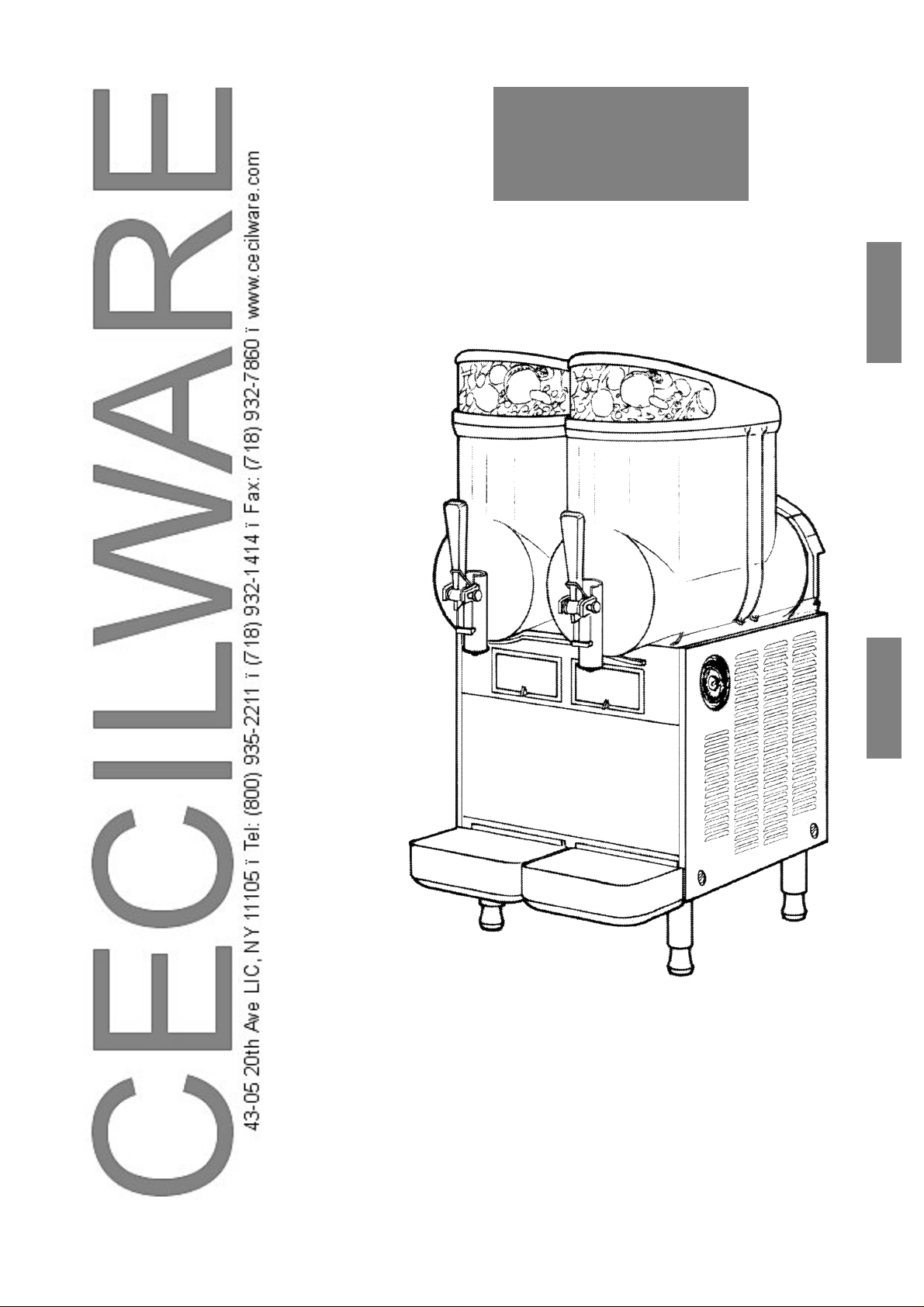
OPERATOR’S MANUAL
MANUAL DE INSTRUCCIONES
NHT2-UL
NHT3-UL
ENGLISH
ENGLISH
ESPAÑOL
NS17A


NHT UL
3
ENGLISH
This dispenser is manufactured under one or more of th e following U.S.patents and/or other pending paten ts:
Este aparato está cubierto por una o varias de las siguientes patentes y/o otras solicitudes de patente ya
registradas:
U.S.A. 4,696,417
U.S.A. 5,906,105
ENGLISH
ESPAÑOL
INDICE GENERALE
1 TECHNICAL CHARACTERISTICS ........................................................................................................................ 4
2 INTRODUCTION .................................................................................................................................................... 4
3 INSTALLATION ...................................................................................................................................................... 4
4 TO OPERATE SAFELY ......................................................................................................................................... 5
5 OPERATING PROCEDURES ................................................................................................................................ 5
5. 1 DESCRIPTION OF CONTROLS .................................................................................................................. 5
5. 2 OPERATION HELPFUL HINTS ................................................................................................................... 6
5. 3 CLEANING AND SANITIZING PROCEDURES ........................................................................................... 7
5. 3. 1 DISASSEMBLY ............................................................................................................................... 7
5. 3. 2 CLEANING ...................................................................................................................................... 8
5. 3. 3 SANITIZING ..................................................................................................................................... 9
5. 3. 4 ASSEMBLY ..................................................................................................................................... 9
5. 4 IN-PLACE SANITIZATION ................................................................................................................... ... ... 10
5. 5 REAR SEAL MAINTENANCE .................................................................................................................... 10
6 ROUTINE MAINTENANCE .................................................................................................................................. 10
6. 1 MAINTENANCE (TO BE CARRIED OUT BY QUALIFIED SERVICE PERSONNEL ONLY) ..................... 11
7 DEFROST TIMER (OPTIONAL) .......................................................................................................................... 11
INDICE GENERAL
1 CARACTERISTICAS TECNICAS ....................................................................................................................... 12
2 INTRODUCCION ...................................................................................................................................... .. ... ...... 12
3 INSTALACIÓN .................................................................................................................................... ................. 12
4 PARA UN FUNCIONAMIENTO SEGURO .................................................................................................. ... ... ... 13
5 INSTRUCCIONES DE EMPLEO .............................................................................................................. .. ......... 13
5. 1 DESCRIPCION DE LOS MANDOS ........................................................................................................... 13
5. 2 SUGERENCIAS ..................................................................................................................... .................... 14
5. 3 LIMPIEZA ................................................................................................................................................... 15
5. 3. 1 DESMONTAJE .............................................................................................................................. 15
5. 3. 2 LAVADO ............................................................................................................................. ........... 16
5. 3. 3 HIGIENIZACION DEL DISTRIBUIDOR DESMONTADO .............................................................. 16
5. 3. 4 REMONTAJE ................................................................................................................... .............. 17
5. 4 HIGIENIZACION DEL DISTRIBUIDOR MONTADO .................................................................................. 18
5. 5 MANTENIMIENTO JUNTA POSTERIOR ................................................................................................... 18
6 MANUTENCION ...................................................................................................................... .. .......................... 18
6. 1 MANUTENCION (SOLAMENTE POR EL SERVICIO POSTVENTA) ........................................................ 18
7 CONTADOR DE DESCONGELACION (OPCIONAL) .......................................................................................... 19

NHT UL
4
1 TECHNICAL CHARACTERISTICS
The electric diagram of the dispenser is located in the
inner part of the dispensing side panel.
Specifications are subject to change without notice.
2 INTRODUCTION
Please read all sections of this manual thoroughly to familiarize
yourself with all aspects of the unit.
Like all mechanical products, this machine will require cleaning
and maintenance. Besides, dispenser working can be
compromised by operator’s mistakes during disassembly an d
cleaning. It is strongly recommended that personnel
responsible for the equipment’s daily operations, disassembly,
cleaning, sanitizing and assembly, go through thes e
procedures in order to be properly trained and to make sure
that no misunderstandings exist.
3 INSTALLATION
1 - Remove the corrugate container and packing materials
and keep them for possible future use.
2 - Inspect the uncrated unit for any possible damage. If
damage is found, call the deliverin g carrier imme diately to
file a claim.
3 - Install the unit on a counter top that will support the
combined weight of dispenser and product bearing in
mind what is stated in the preceding point 1
IMPORTANT warning.
4 - A minimum of 15 cm (6”) of free air space all around the
unit should be allowed to guarantee adequate ventilation.
5 - Ensure that the legs are screwed tightly into the base of
the machine.
Replace the standard legs originally installed with the 100
mm (4”) legs whenever they are provided with the unit.
6 - Before plugging the unit in, check if the voltage is the same
as that indicated on the data plate. Plug the unit into a
grounded, protected single phase electrical supply
according to the applicable electrical codes and the
specifications of your machine. When the unit has no plug,
install a proper grounded plug, in compliance with
electrical codes in force in your area, suitable to at least
10 Amp 25 0 Volt ( 220-230 Volts 50-60 Hz areas) and
20 Amp 250 Volt (100-115 Volts 50-60 Hz areas)
applications. Should you prefer to connect the unit directly
to the mains, connect the supply cord to a 2-pole wall
breaker, whose contact opening is at least 0.125”. Do not
use extension cords.
7 - The unit doesn’t come presanitized from the factory.
Before serving products, the dispenser must be
disassembled, cleaned and sanitized. a ccording to this
handbook instructions (chapter
5.3 CLEANING AND SANITIZING PROCEDURES).
4 TO OPERATE SAFELY
1 - Do not operate the dispenser without reading this
operator’s manual.
2 - Do not operate the dispenser unless it is properly
grounded.
3 - Do not use extension cords to connect the dispenser.
4 - Do not operate the dispenser unless all panels are
restrained with screws.
5 - Do not obstruct air intake and discharge openings: 15 cm
(6”) minimum air space all around the dispenser.
6 - Do not put objects or fingers in panels louvers and faucet
outlet.
7 - Do not remove bowls, augers and panels for cleaning or
routine maintenance unless the dispenser is disconnected
from its power source.
NHT 2 UL
NHT 3 UL
Transparent removable bowls n 2 3
Capacity of each bowl, approx. Gal 2.5 2.5
Dimensions:
width Inches 14.25 21
depth Inches 18.25 18.25
height Inches 27.75 27.75
Net weight, approx. Lbs 81.5 108
Gross weight, approx. Lbs 95 125
Adjustable thermostats n 2 3
Hermetic compressor
Air-cooled condenser
Overload protector
Safety pressure switch
Noise level lower than 70 dB (A)
IMPORTANT
Read electrical ratings written on the data plate of the
individual units; the data plate is adhered on the
dispensing side panel of the unit, just be hind the drip
tray (the right side drip tray in multiple bowl models).
The serial number of the unit (preceded by the
symbol #) is adhered inside the left switch box. Data
plate specifications will always supersede the
information in this manual.
IMPORTANT
When handling the machine never grasp it by the bowls
or by the evaporator cylinders. The manufacturer
refuses all responsibilities for possible damages which
may occur through incorrect handling.
ATTENTION
Failure to provide proper electrical ground accordi ng to
applicable electrical codes could result in serious shock
hazard.
NHT UL
5
ENGLISH
5 OPERATING PROCEDURES
1 - Clean and sanitize the unit according to the instructions in
this manual. See chapter 5.3 CLEANING AND
SANITIZING PROCEDURES.
2 - Fill the bowls with product to the maximum level mark. Do
not overfill.
The exact quantity of product (expressed as liters and
gallons) is shown by marks on the bowl.
3 - In case of products to be diluted with water, pour water into
bowl first, then add correct quantity of product. In case of
natural squashes, it is advisable to strain them, in order to
prevent pulps from obstructing the faucet outlet.
4 - To obtain the best performance and result, use bases
designed to be run in Granita freezers. Such bases have a
sugar content of 34 degrees Baumé corresponding to 64
degrees Brix.
For soft drinks the bases are to be diluted with more water,
on a 1 plus 5/5.5 basis.
In any case follow the syrup manufacturer’s instructions for
both Granita and soft drink recipes.
If natural juices (e.g. lemon, orange) as well as sugarless
products (e.g. coffee) are used, dissolve 5.3 - 7 oz of sugar
per 0.25 gallons.
5 - Install the covers and check that they are correctly placed
over the bowls. The dispenser must always run with the
covers installed to prevent a possible contamination of the
product.
6 - Set the control switches as shown in chapter
5.1 DESCRIPTION OF CONTROLS.
7 - Always leave the dispenser on, as the refrigeration stops
automatically when Granita reaches the proper thickness.
The mixers will continue to turn.
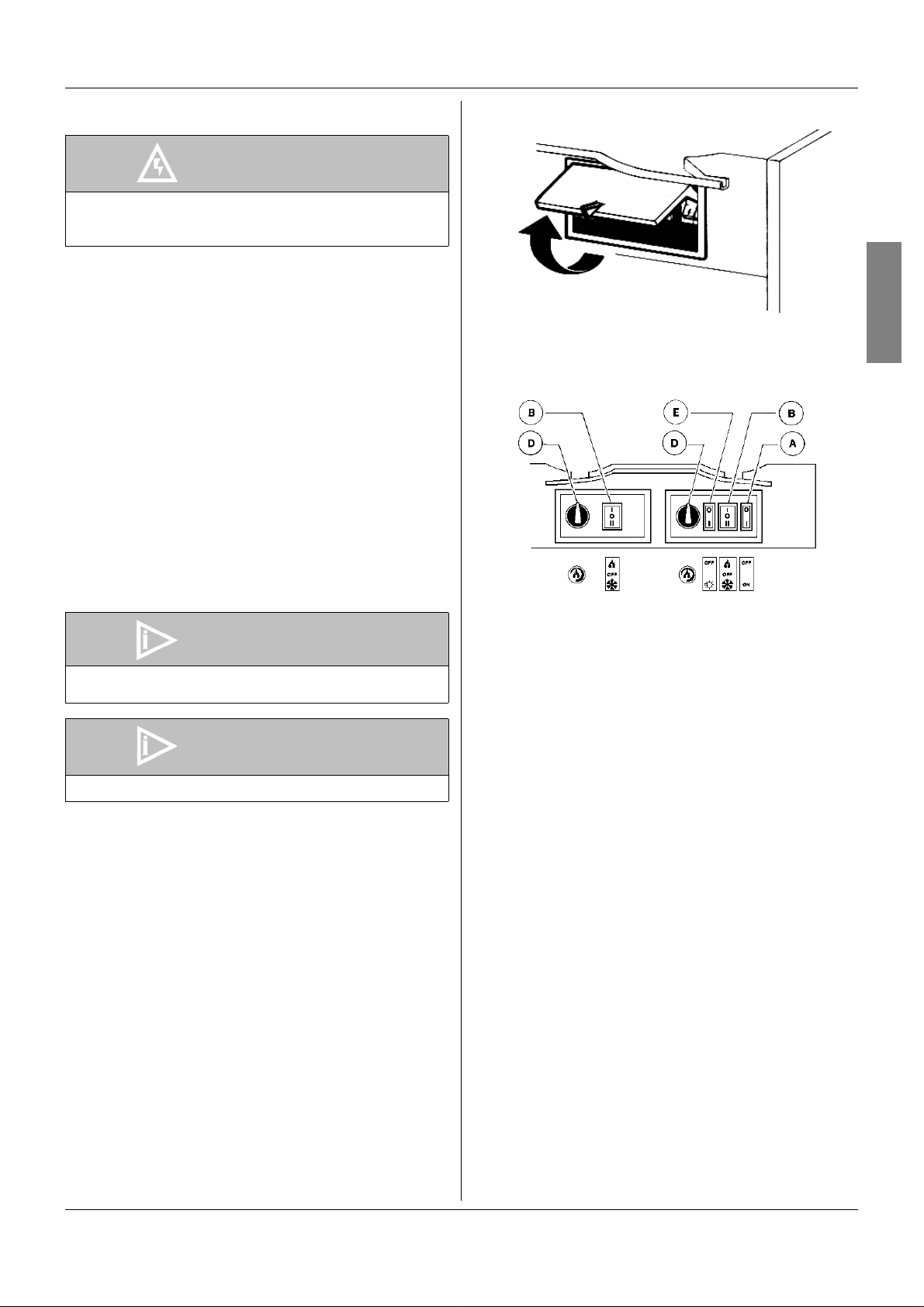
5. 1 DESCRIPTION OF CONTROLS
The dispenser is equipped with a p ower switch and a light
switch. In addition each bowl is individually operated by a
mixer/refrigeration switch. In fact it is possible to dispense both
soft drinks and Granita.
When a bowl is in Soft Drink mode the beverage temperature
is controlled by the corresponding thermostat.
When a bowl is in Granita mode the mix viscos ity is co ntrolle d
by the corresponding adjustment screw located in the rear wall
of each container (for temperature and viscosity setting make
reference to chapter 5.2 OPERATION HELPFUL HINTS).
All the switches are located on the faucet side of the dispenser
in switch panels protected by switch covers (see figure 1).
figure 1
With reference to figure 3 dispenser controls functions are as
follows:
figure 2
Power switch (A)
Light switch (E)
Mixer/refrigeration switch (B)
Thermostat (D)
To operate the unit:
1 - Set the power switch to I position.
2 - Set the mixer/refrigeration switches as follows:
- to the I position to get soft drink.
- to the II position to get Granita.
3 - Set the light switch to I position.
ATTENTION
In case of damages, the power cord must be replaced
by qualified personnel only in order to prevent any
shock hazard.
IMPORTANT
However Granita mix may be done, its Brix (sugar
percent content) must be at least 13.
IMPORTANT
Operate the dispenser with food products only.
0 position : power is turned OFF to all functions.
I position : power is turned ON to all functions
and the other switches are enabled.
The fan motor runs.
0 position : all top cover lights are OFF.
I position : all top cover lights are ON, provided
that power switch (A) is set to I.
I position : mixer and refrigeration ON.
SOFT DRINK mode.
0 position : OFF.
II position : mixer and refrigeration ON.
GRANITA mode.
Turn clockwise : to decrease temperature
Turn counterclockwise : to increase temperature

NHT UL
6
5. 2 OPERATION HELPFUL HINTS
1 - Granita viscosity adjustment: proper Granita viscosity is
factory preset. To change the viscosity, if needed, use a
standard screwdriver to turn the adjustment screw located
in the rear wall of each container as follows (see figure 3):
- towards right (clockwise) to obtain a thicker product (the
indicator F will go down in opening G).
- towards left (counterclockwise) to obtain a thinner
product (the indicator F will go up in opening G).
figure 3
2 - Beverage temperature adjustment: proper beverage
temperature is factory preset. To reset, turn the knob
located in each switch box as follows:
- towards right (clockwise) to decrease temperature.
- towards left (counterclockwise) to increase temperature.
Note: beverage temperature is controlled by the
thermostat only when the mixer/refrigeration
switch(es) are in I position, Soft Drink mode.
3 - When the mixer / refrigeration switch(es) are set in I
position, Soft Drink mode, it is possible to manually switch
off the refrigeration by turning completely towards left
(counterclockwise) the thermostat knob until it clicks.
4 - The le ngth of time for freeze down of Granita is governed
by many variables, such as ambient temperature, mix
initial temperature, sugar content (Brix level) and viscosity
setting.
5 - To shorten Granita recovery time and increase
productivity, it is advisable to pre-chill the product to be
used in the dispenser.
6 - To shorten Granita recovery time and increase
productivity, the bowl should be refilled after the product
level drops lower than half of the evaporator cylinder and
at the start of each day.
7 - For good product conservation the dispenser must run
overnight, at least in Soft Drink mode.
If this is not possible and product is left in the bowls
overnight, the mixer/refrigeration switches must be set to
the I position at least one hour before the unit is switched
off. This eliminates any block of iced product forming
overnight, which could result in damage to mixers or to
their motor when the unit is switched back on. In any case,
before the unit is restarted, make sure that no blocks of ice
have been formed; if so, they are to be removed before the
unit is switched on. Overnight operation in drink mode also
eliminates possible ice accumulation from condensation all
around the bowls.
8 - Mixers must not be turned off when frozen product is in the
bowl: if not agitated, the product may freeze to a solid
block of ice. If the mixers are turned back on in this
situation, damage to the mixers and their motor may result.
Therefore, mixers may be restarted only after product is
melted.
9 - The dispenser must be able to emit heat.
In case it seems excessive, check that no heating source
is close to the unit and air flow through the slotted panels is
not obstructed by wall or boxes. Allow at least 15 cm (6”) of
free clearance all around the dispenser.
In any case if the product in the bowls is frozen and the
safety pressure switch warning light is OFF the unit is
running properly.
10 -Restrictor cap: when the unit is used in Soft Drink mode it
is advisable to install the restrictor cap on the faucet outlet
in order to reduce the drink outflow (see figure 4).
figure 4
NHT UL
7
ENGLISH
5. 3 CLEANING AND SANITIZING
PROCEDURES
1 - Cleaning and sanitizing of the dispenser are
recommended to guarantee the conservation of the best
product taste and the highest unit efficiency. This section
is a procedural guideline only and is subject to the
requirements of the local Health Authorities.
2 - Prior to the disassembly and cleaning, the machine must
be emptied of product. To do this proceed as follows:
- set the power switch to I position
- set mixer/refrigeration switch(es) to I position (Soft Drink
mode)
- place a pail under each faucet and drain all product from
bowls
- set all control switches to the 0 position.
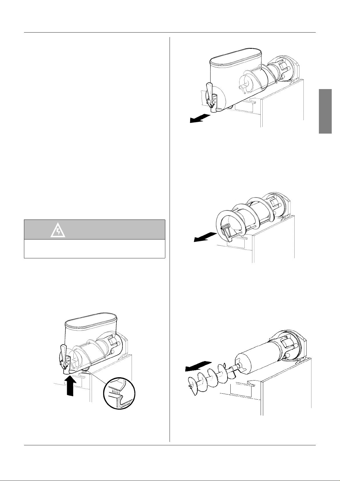
5. 3. 1 DISASSEMBLY
1 - Remove cover from the bowl.
2 - Remove the bowl by lifting its faucet side up and off the
fastening hooks (see figure 5) and slide it out (see figure
6).
figure 5
figure 6
3 - Slide the outer spiral out (see figure 7) and then the inside
auger. Frequently remove the rear seal by sqeezing it to
break the suction grip (see figure 8).
figure 7
figure 8
ATTENTION
Before any disassembly and/or cleaning procedure
make sure that the dispenser is disconnected from its
power source.

NHT UL
8
4 - Remove the bowl gasket from its seat (see figure 9).
figure 9
5 - Dismantle the faucet assembly (see figure 10).
figure 10
6 - Slide the drip tray out and empty it.
5. 3. 2 CLEANING
1 - Prepare at least two gallons of a mild cleaning solution of
warm (45-60 °C / 120-140 °F) potable water and
dishwashing detergent. Do not use abrasive detergent.
Important: if present, follow label directions, as too strong
a solution can cause parts damage, while too mild a
solution will not provide adequate cleaning.
2 - Using a brush, suitable for the purpose, thoroughly clean
all disassembled parts in the cleaning solution.
3 - Do not immerse the lighted top covers in liquid. Wash them
apart with the cleaning solution. Carefully clean their
undersides.
4 - In the same manner clean the evaporator cylinder(s) using
a soft bristle brush.
5 - Rinse all cleaned parts with cool clean water.
5. 3. 3 SANITIZING
Sanitizing should be performed immediately prior to starting
the machine. Do not allow the unit to sit for extended periods of
time after sanitization.
1 - Wash hands with a suitable antibacterial soap.
2 - Prepare at least two gallo ns of a warm (45-60 °C / 120-
140 °F ) sanitizing solution (100 P PM available chlorine
concentration or 1 spoon of sodium hypoclorite diluted with
half a gallon of water) according to your local Health
Codes and manufacturer’s specifications.
3 - Place the parts in the sanitizing solution for five minutes.
4 - Do not immerse the lighted top covers in liquid. Carefully
wash their undersides with the sanitizing solution.
5 - Place the sanitized parts on a clean dry surface to air dry.
6 - Wipe clean all exterior surfaces of the unit. Do not use
abrasive cleaner.
5. 3. 4 ASSEMBLY
1 - Slide the drip tray into place.
2 - Lubricate faucet piston, inside auger and outer spi ral (see
points A, B and C of figu re 11) only with the grea se
supplied by the manufacturer or other food grade
ATTENTION
Before any disassembly and/or cleaning procedure
make sure that the dispenser is disconnected from its
power source.
IMPORTANT
Do not attempt to wash any machine components in a
dishwasher.
IMPORTANT
In order to prevent any damages to the dispenser use
only a detergent suitable with plastic parts.
ATTENTION
When cleaning the machine, do not allow excessive
amounts of water around the electrically operated
components of the unit. Electrical shock or dam age to
the machine may result.
 Loading...