


Operator Manual
Compact Powdered Beverage Dispenser
GB Models 1CP, 2CP, 3CP
Model GB3CP |
Model GB1HC-CP |
Model GB2CP |
Table of Contents
Safety Information |
..................2 |
Maintenance ........................... |
8 |
Installation............................... |
3 |
Troubleshooting Guide......... |
11 |
Operation ................................ |
6 |
Parts Diagram and List.......... |
12 |
Cleaning................................... |
7 |
Wiring Diagrams ................... |
15 |
Thank you for purchasing this quality powdered beverage dispenser. For your safety and the safety of others, read all warnings and the operator manual before installing or using the product. Properly instruct all operators. Keep training records. For future reference, record serial number here: 
Grindmaster-Cecilware
4003 Collins Lane, Louisville, KY 40245 USA Phone: 502.425.4776 Toll Free: 800.695.4500 Fax: 502.425.4664
Web: gmcw.com Email: info@gmcw.com
Grindmaster-Cecilware provides the industry’s BEST warranty. Visit gmcw.com for warranty terms and conditions.
©2016 Grindmaster-Cecilware |
0516 Form # CW-318-01 |
Printed in USA |
Part # 390-00015 |
Safety Information
Important Safety Information
This is the safety alert symbol. It is used to alert you to potential personal injury hazards. Obey all safety messages that follow this symbol to avoid possible injury or death.
For your safety and the safety of others, read all warnings and the operator manual before installing or using the product.
DANGER: This term warns the user of imminent hazard that will result in serious injury or death.
WARNING: This term refers to a potential hazard or unsafe practice, which could result in serious injury or death. CAUTION: This term refers to a potential hazard or unsafe practice, which could result in minor or moderate injury.
NOTICE: This term refers to information that needs special attention or must be fully understood.
 WARNING
The appliance is not intended for outdoor use.
Do not clean with pressurized water or use in an area where pressurized water may be used.
Cleaning and maintenance shall be made only by properly trained persons with supervision.
 CAUTION
Lifting hazard. Single person lift could cause injury. Use assistance when moving or lifting.
For safe and proper operation, the appliance has to be placed in a stable, vertical position.
The appliance is not to be used by persons with reduced physical, sensory, or mental capabilities, or lack of experience and knowledge, unless they have been given supervision or instruction. Be sure to provide supervision or instruction concerning use of the appliance in a safe way and understand the hazards involved.
Children must be supervised to ensure they do not play with the appliance.
The appliance is only to be installed in locations where it can be overseen by trained personnel.
NOTICE
To avoid damaging unit, turn on power and wait for tank to fill with water before turning on heater.
Observe machine voltage configuration. Do not apply improper voltage to machine or damage to machine will occur.
Do not use extension cord.
2 |
Cecilware® |
GB Series |

Installation

 CAUTION: Lifting hazard. Single person lift could cause injury. Use assistance when moving or lifting.
Water Inlet Connection:
NOTICE: This equipment is to be installed to comply with the applicable Federal, State, or local plumbing codes having jurisdiction. In addition:
1.A quick disconnect water connection or enough extra coiled tubing (at least 2x the depth of the unit) so that the machine can be moved for cleaning underneath.
2.An approved backflow prevention device, such as a double check valve to be installed between the machine and the water supply.
The GB beverage dispenser is equipped with a 1/4" Flare Water Inlet fitting which is located on the left side in the back of the base (when looking at the machine from the front).
Water pipe connecting and fixtures directly connected to a potable water supply shall be sized, installed, and maintained in accordance with Federal, State, and Local codes.
HIGHLY RECOMMENDED:
A WATER SHUT-OFF VALVE and A WATER FILTER, preferably a combination Charcoal/Phosphate Filter, to remove odors and inhibit lime and scale build up in the machine.
Note: In areas with extremely hard water, a water softener must be installed in order to prevent mineral deposits that could result in malfunctioning of the equipment and in order not to void the warranty.
Unpacking Instructions
Carefully unpack the GB Machine and inspect immediately for shipping damage. Your GB Machine was shipped in a carton designed to give it maximum protection in normal handling. It was thoroughly inspected before leaving the factory. In case of damage, contact the shipper not GrindmasterCecilware.
After the machine has been unpacked and placed on a counter, pull out the stainless steel drip tray. It should contain the following:
• 1/4” Flare Water Inlet Fitting.
GB Series |
Cecilware® |
3 |
Installation (continued)
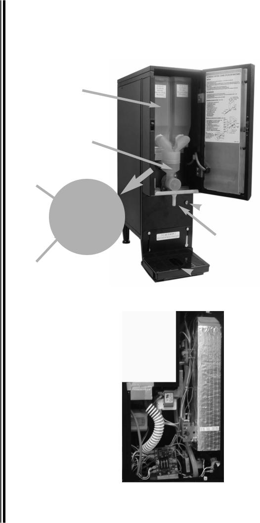
Description and Location of Components
Note: Refer to following illustration for description and location of COMPONENTS and CONTROLS.
Heater Switch located in rear
Hoppers
Mixing Chamber
Rinse Switch
Hoppers
 Pilot Light for Heater
Spout
Power Switch
 Drip Tray
Rear of machine
4 |
Cecilware® |
GB Series |

Installation (continued)
1.HOPPERS: Pull door open to access the hoppers.
•The hoppers hold 4 or 8 lbs. (1.8 or 3.6 kg) of Cappuccino product, depending on model number.
•To remove the hoppers, swing the compartment door open and lift out the hoppers.
•To reposition the hoppers in the compartment, slide the hopper base back between the rails until the 1/4" pin at the bottom of the hopper base falls into the 1/4" positioning hole of the compartment base cover.
2.RINSE SWITCH: With the door open, the rinse switch is located on the left side of the Mixing Chamber, in the hopper compartment.
•It disengages the hopper motors and allows only water to be dispensed.
•It is used for flushing out the Whipper Chambers and to adjust the water dispense valves for proper flow rates.
3.HEATER SWITCH: This switch is located in the rear, on the left side.
•Its primary function is to shut off the heating element during the initial priming, start-up operation of the machine, or whenever the tank is being drained for service.
Note: The Power Switch and Heater Switch must be ON in order for the elements to operate.
4.POWER SWITCH: With the door open, the rinse switch is located on the left side of the Mixing Chamber, in the hopper compartment. The power switch controls all power to the machine including the heater elements.
5.WATER LEVEL CONTROLS: Under normal conditions and operation, the water level in the tank should not drop more than 1/2" (13 cm) from the probe. If it does, the tank is not refilling fast enough. Check the water line and water filter; they may need cleaning or replacing.
1. |
Tank Control Board |
Part# 349-00012 |
|
(Export 240V |
Part# L776AL) |
2. |
Water inlet valve |
Part# CD257L |
|
(Export 240V |
Part# CD258L) |
3. |
Water Level Sensor |
Part# K695QL |
Start-up Procedure
NOTICE: Make sure that the Heater Switch, located in rear of unit, is in the OFF position.
1.Connect the 1/4" dia. copper waterline to the 1/4" flare water inlet fitting of the valve.
2.Plug the power cord into a proper receptacle.
3.Activate the Power Switch (Toggle Up). The red power indicator light and the green dispense buttons will light up and the tank will start filling. Allow approximately 4-5 minutes for the tank to fill.
4.Activate the Heater Switch. Allow approximately 10-30 minutes for the water to reach a temperature of 190°F (88°C). The heat up time will depend on the water inlet temperature, the input voltage, and the wattage of the elements in the machine.
5.Place a 8 oz. (240ml) or larger cup under the dispense nozzle, press and hold the dispense switch for 6 seconds. The machine will dispense water at the rate of 1 oz. (30ml) per second. Repeat it several times to check for consistent output. This procedure checks that the dispense valve is not air-locked.
6.While the tank is heating, remove the hoppers, load them with products, and reposition them back in the machine. When the green ready light comes on, the tank has reached its brew temperature and the machine is ready to dispense the first cup of Cappuccino or Hot Chocolate.
Filling the Hoppers
1.Pull door open to access the hoppers.
2.Fill each hopper with the correct product.
3.Reposition hoppers in the hopper compartment, making sure the hoppers are properly seated.
If you need help, call Grindmaster-Cecilware Technical Service Department, (502) 425-4776 or (800) 695-4500 (USA & Canada only) 8 AM - 6 PM EST.
Prior authorization must be obtained from Grindmaster-Cecilware for all warranty claims.
GB Series |
Cecilware® |
5 |
Operation
Your new powdered beverage dispenser is easy to operate and maintain. Before you place it in service, please have all personnel familiarize themselves with these instructions. Keep this manual in a convenient place for ready reference.
How to Operate
To dispense a cup of Hot Chocolate, Cappuccino, or Coffee:
•Place an 8 oz. (240ml) or larger cup under selected drink dispense nozzle.
•Push and hold brew button until cup is 2/3 full, then release button.
Adjustments
Water Flow Rate Adjustment
Adjust water flow rate to correct level in Whipping Chamber.
The Dispense Valves are factory adjusted for a maximum Flow Rate of 1 to 1.3 oz./sec (30-38 ml/sec). [Approximate settings: 1.3 oz./sec (38 ml/sec) for COFFEE and CAPPUCCINO]
Exceeding this Flow Rate will cause the Mixing Chamber to overflow.
Note: To access the Water Dispense Valves, open door and remove Hoppers.
TO ADJUST WATER FLOW RATE:
1.Open door and remove hoppers. Locate Dispense Valve behind hoppers, mounted on tank.
2. Locate adjustment screw on Dispense Valve.
3. Using Allen Key or flat screwdriver rotate, 1/4 turn at a time,
CLOCKWISE to decrease water flow, or
COUNTERCLOCKWISE to increase water flow.
4. Check water flow output, 


 after each 1/4 turn.


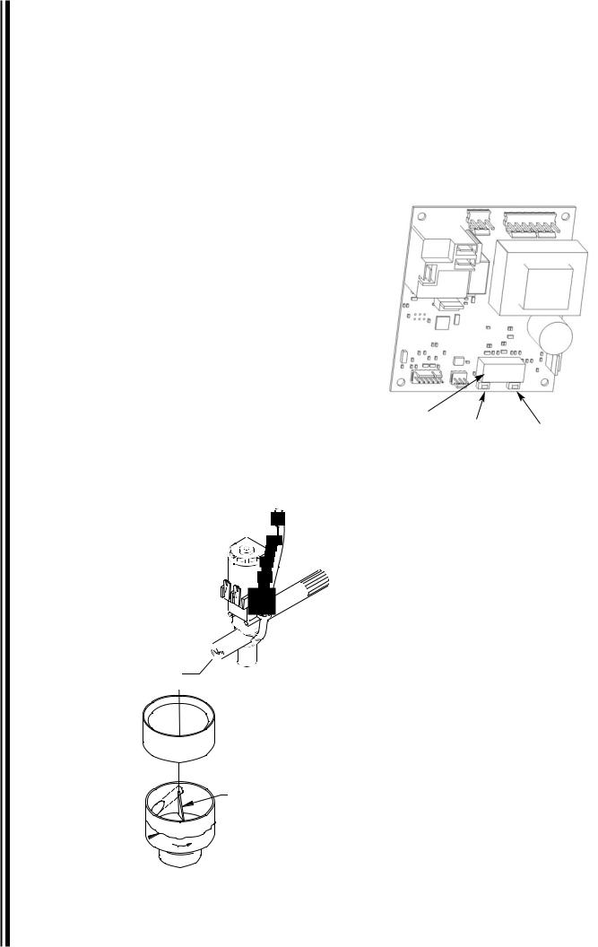
WATER FLOW ADJUSTMENT
DISPENSE VALVE
|
DISPENSE CAP |
Adjust Water Flow Rate so that the |
|
water level reaches half way up in |
|
the Mixing Chamber, as shown. |
TRIANGULAR RIB |
CORRECT WATER 
LEVEL FOR MAX
FLOW RATE.
MIXING CHAMBER
Temperature Adjustment (Tank Control Board
Type)
1.Locate the Tank Control Board.
2.Press button under right side of display to increase temperature.
3.Press button under left side of display to decrease temperature.
4.Pressing both buttons simultaneously will reset to default 190°F (88°C).
190° |
|
|
Display |
Increase |
|
Decrease |
||
|
Temperature Adjustment (Thermostat Type)
1.Locate Thermostat: Remove the right side panel. Thermostat is mounted on side of tank.
The GB beverage dispensers are factory set to deliver hot brewing water at 190°F (88°C) with the thermostat knob turned to full ON position. If adjustments should be necessary to increase or decrease the water TEMPERATURE, proceed as follows:
Note: Set the Rinse Switch to ON. This will disengage the Hopper Motors when dispensing water for Temperature measurements.
2.To INCREASE the water temperature - With the Thermostat Knob to its maximum clockwise position, remove the knob and locate the slotted adjustment screw inside the hollow thermostat shaft. Using a narrow-bladed screwdriver, engage slotted adjustment screw and turn it ¼ turn slowly counter-clockwise.
Allow a few minutes for the temperature to reach set level. The Heater Light will go ON, indicating the heating element is activated, wait for it to go OFF, indicating that the water has reached new set temperature. Take a temperature reading and repeat if necessary.
3.To DECREASE the water temperature - simply turn the Thermostat Knob one notch counter-clockwise to the next lower dial setting.
6 |
Cecilware® |
GB Series |
 Loading...