

Page 1
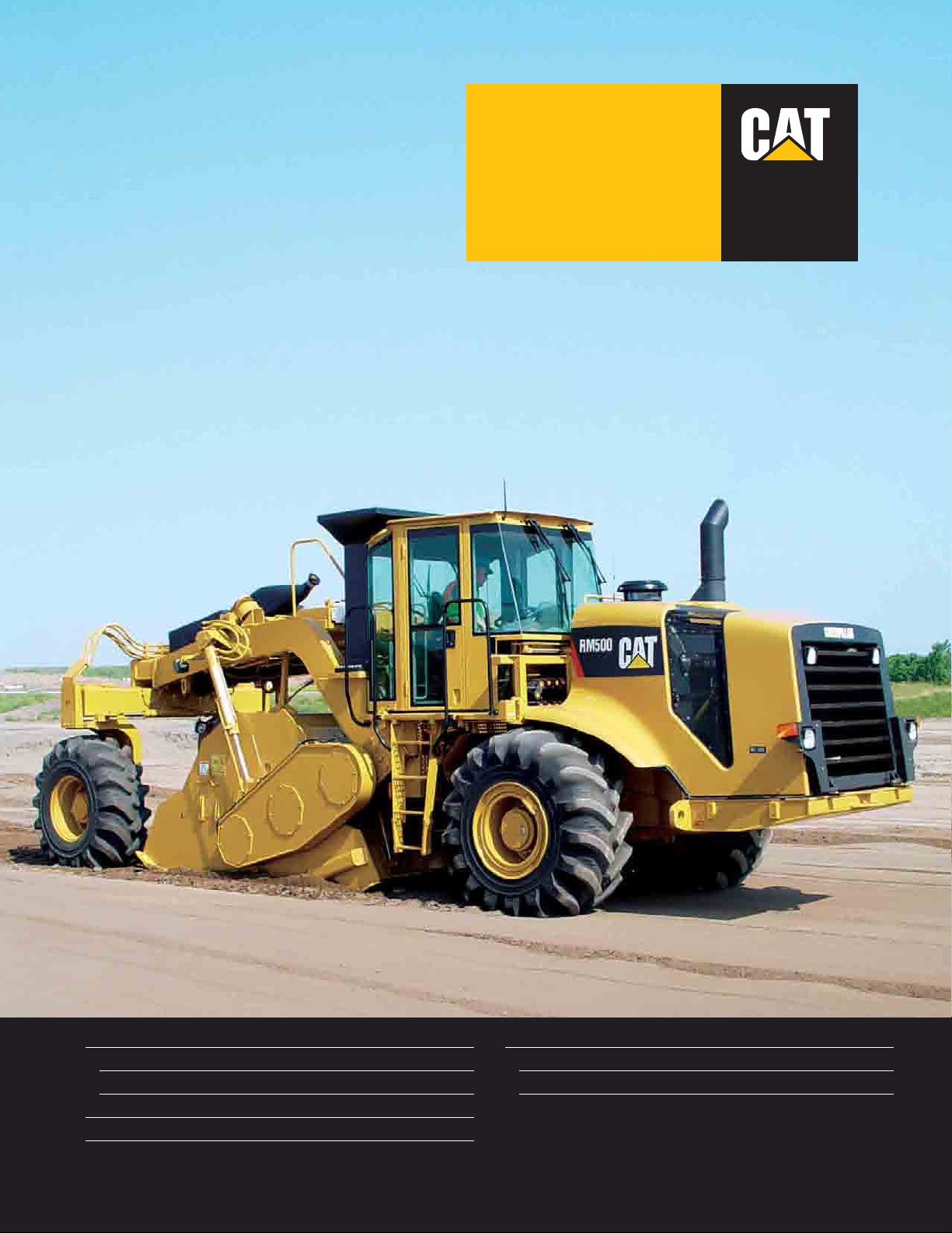
Operating Weight (with ROPS and cab)
with universal rotor 28 410 kg
with combination rotor 27 150 kg
Cat® C15 Engine with ACERT™ Technology
Gross Power (SAE J1995) at 2000 rpm 403 kW/548 hp
Net Power (ISO 9249) at 2000 rpm 403 kW/548 hp
Rotor Width 2438 mm
Rotor Depth (maximum) 508 mm
RM500
Rotary Mixer
®
Page 2
2
Productivity, Serviceability and Comfort in a Durable Package
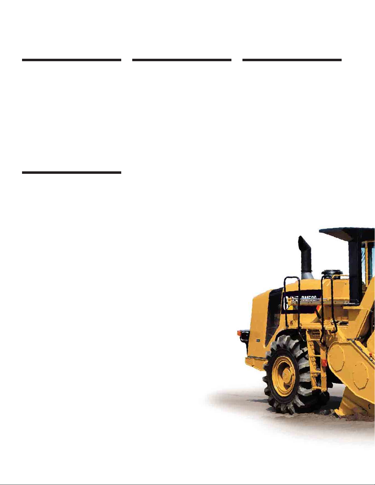
The new RM500 offers enhanced production capabilities, optimized performance, simplified
service and exceptional operator comfort.
C15 Engine with ACERT™ Technology
ACERT™ Technology works at the
point of combustion to optimize engine
performance and provide low exhaust
emissions. The C15 engine with
ACERT Technology provides clean
burning power. Electronically
controlled on-demand variable speed
cooling fan provides the lowest overall
noise levels and high ambient operation
capability. pg. 4
Cab
The optional cab increases machine
utilization, provides greater year-round
comfort and offers reduced interior
sound levels. The pressurized cab slides
side-to-side and includes a rotating
cloth seat, left and right side doors,
tinted windows, front and rear
windshield wipers, heater/defroster and
air conditioning. Sound absorbing floor
mat reduces sound and machine
vibration transmitted to the operator.
pg. 6
Operator’s Station
Ergonomic design emphasizes comfort,
visibility and easy operation. Isolated
operator’s station with heavy-duty
rubber mounts reduce machine
vibration transmitted to the operator.
The hydraulically-assisted platform
slides side-to-side to an infinite number
of positions. A switch on the side
console allows the operator to select
any desired position for good visibility
and comfort. The fully adjustable
steering column and rotating seat are
positioned to provide an optimal
operating position. Machine controls
are grouped and conveniently located to
enhance operator productivity and
reduce fatigue. pg. 5
Serviceability
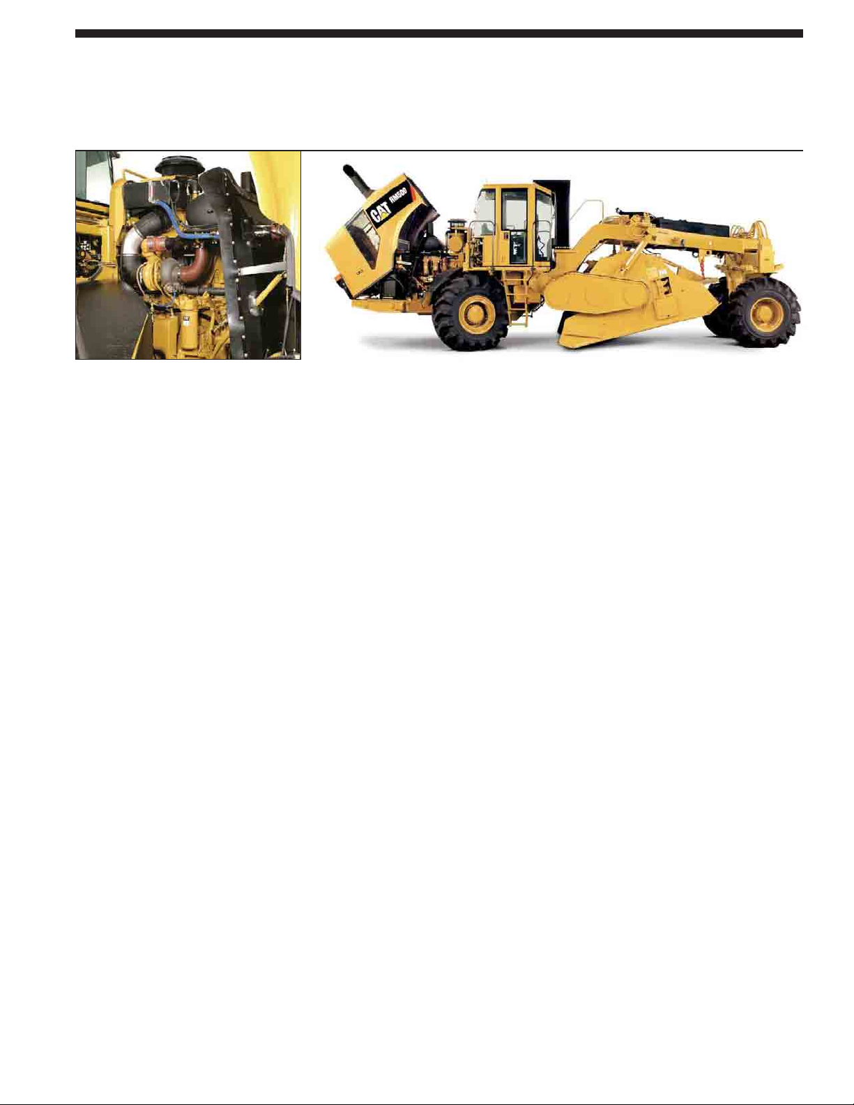
The one-piece fiberglass hood tilts
forward for exceptional access to the
engine and cooling system. Daily
service points are accessible from
ground level and are grouped on one
side of the engine. Hinged ground level
side panels allow total engine access.
Hinged service doors open wide for
access to power train and rotor drive
components. The rotor hood tilts
forward to allow access to the rotor and
cutting tools. Ground level side access
doors on the rotor hood provides
convenient access for easy cutting tool
removal and replacement. pg. 11
Performance and reliability you expect.
The RM500 combines superior performance
and reliability to achieve the most demanding
job specifications while maximizing machine uptime.
With many enhanced features and options, the RM500
is designed to work well in both full depth reclamation
and soil stabilization applications.
Page 3
3
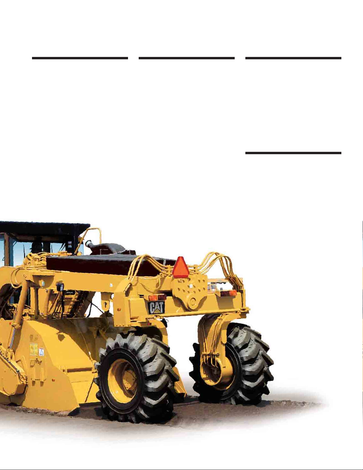
Dual Propel Pumps
The dual propel pumps provides a
separate balanced hydraulic flow to
both the rear and front drive motors
to propel the machine with full-time.
This system enables the operator to
achieve superior tractive effort for soil
stabilization applications that require
maximum cutting depth and that are
also high in moisture content. pg. 8
Rotor Drive
A Caterpillar® powershift transmission
drives the rotor and provides three rotor
speeds for maximum performance in a
variety of materials and cutting depths.
Heavy-duty shear disc or optional
torque limiter protects rotor drive
components from torsional stress and
shock loads. pg. 8
Mixing Chamber
Mixing chamber allows the rotor to
move independently so that the
capacity of the chamber actually
increases in deeper cuts to allow better
material mixing and excellent
gradation. Machine weight is well
distributed to provide stability in the
cut for uniform depth control. pg. 9
Rotor Options
With a choice of two rotor options, the
RM500 can be configured for different
applications and depth specifications.
The universal rotor is intended
primarily to pulverize asphalt layers.
The combination rotor is intended
primarily for use in soil stabilization
with secondary application in light cuts
of asphalt reclamation. pg. 10
Page 4
4
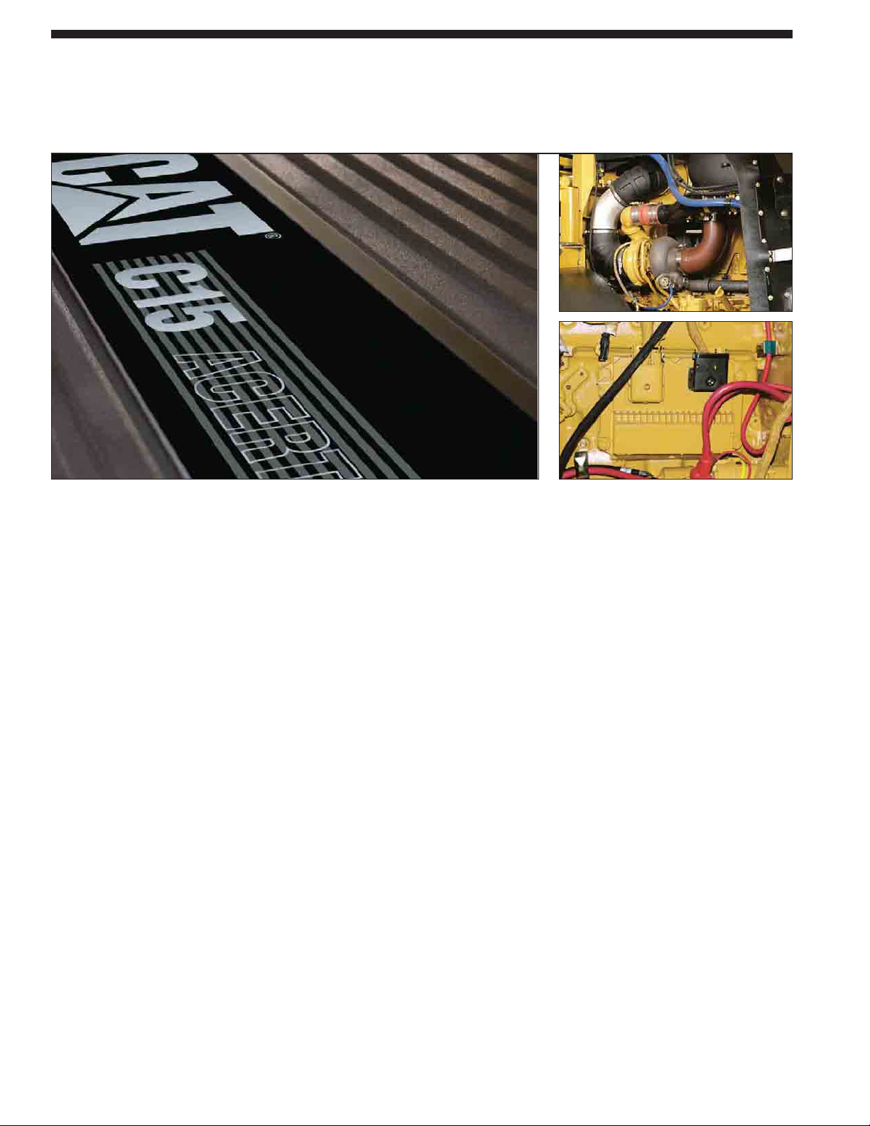
C15 Engine with ACERT Technology
A combination of innovations working at the point of combustion, ACERT Technology
optimizes engine performance while meeting European EU Stage IIIA emission regulations
for off-road applications.
Cat C15 Engine with ACERT Technology.
The C15 engine provides a full-rated
gross power (SAE J1995) of 403 kW at
2000 rpm with a torque of 2356 Nm.
The combination of large displacement
and high torque allow the RM500 to
propel through the toughest materials.
Mechanically-Actuated Electronically
Controlled Unit Injection (MEUI). The
MEUI fuel system is a unique system
that combines the technical
advancement of an electronic control
system with the simplicity of direct
mechanically controlled unit fuel
injection. The MEUI system excels in
its ability to control injection pressure
over the entire engine operating speed
range. These features allow the C15 to
have complete control over injection
timing, duration and pressure.
Multiple Injection Fuel Delivery.
Multiple injection fuel delivery involves
a high degree of precision. Precisely
shaping the combustion cycle lowers
combustion chamber temperatures,
which generates fewer emissions,
optimizes fuel combustion; translating
into more work output for your fuel
cost.
C15 Cylinder Block. The cylinder block
is a one-piece, grey iron block that
features generous ribbing for stiffness
and heavy bearing bulkheads for rigidity
and strength as the crankshaft turns.
This new design supports the engine’s
higher compression ratios and increases
its power density. The incorporation of
straight-thread, o-ring connection points
reduces the loss of engine oil and fluids.
High Cylinder Pressures. High cylinder
pressures combined with tightly
controlled tolerances promote extremely
efficient fuel burn, less blow by and
lower emissions.
Service, Maintenance and Repair.
Easier service, maintenance and
repair is accomplished by monitoring
key functions and logging critical
indicators. Advanced electronic
diagnostic capabilities are possible
using Cat Electronic Technician.
Turbocharged and Air-to-Air
Aftercooling (ATAAC). The turbocharged
air-to-air aftercooling system provides
high horsepower with increased
response time while keeping exhaust
temperatures low for long hours of
continuous operation.
Air-to-Air Aftercooling. Air-to-air
aftercooling keeps air intake
temperatures down and in concert with
the tight tolerance combustion chamber
components, maximizes fuel efficiency
and minimizes emissions.
New turbocharger, unique cross-flow
head, single, rear driven, overhead cam
and a more efficient intake manifold
generate significant improvements
in air flow. This generates significant
improvements in efficiency and reduced
emissions.
ADEM™ A4 electronic Control Module.
The ADEM A4 electronic control
module manages fuel delivery, valve
timing and airflow to get the most
performance per liter of fuel used.
The control module provides flexible
fuel mapping, allowing the engine to
respond quickly to varying application
needs. It keeps track of engine and
machine conditions while keeping the
engine operating at peak efficiency.
Page 5
5
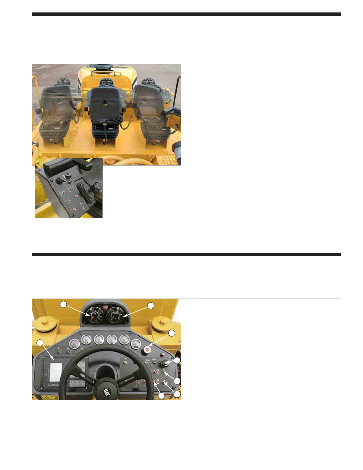
Operator’s Station
Ergonomic design emphasizes operator comfort, visibility and easy operation.
The sliding platform slides side-to-side to increase versatility and productivity while
reducing operator fatigue.
Hydraulically-assisted sliding platform. The operator can
position the platform to any desired position to provide clear,
all-around visibility to both sides of the machine. Platform
can be accessed from either side of the machine.
Comfortable and durable seat. The seat has adjustable fore/aft
position, bottom cushion height, suspension stiffness and flipup arm rests. Seat and side control console rotates to seven
positions to enhance operator comfort.
Controls are conveniently located for easy one-handed
control while seated. Propel lever with center detent allows
forward/reverse operation and variable machine speed.
Adjustable steering column. The telescoping and tilt feature
of the steering column provides a comfortable operating
position for the operator.
Operational Controls
All machine controls, switches and gauges are positioned to minimize operator fatigue and
maximize productivity.
Clear instrumentation. Includes gauges for engine oil
pressure, engine coolant temperature, hydraulic oil
temperature, rotor drive transmission oil temperature,
charging system voltage and fuel level.
Large analog gauges. Large gauges display propel ground
speed, engine rpm, engine hour meter and fault codes.
Electronic monitoring system. Input signals are constantly
monitored from sensors and switches in various machine
systems and operator is alerted if a problem occurs.
Load control selection switch. Controls propel speed
manually or automatically by the ECM.
Automatic steering control. Four steering modes enable
maneuvering in tight quarters: front steer only, crab steer,
coordinated steer and rear steer only.
1 Electronic Monitoring System
2 Ground Speed Indicator
3 Engine Tachometer
4 Park Brake Switch
5 Propel Speed Selector Switch
The side console features a
padded arm rest, four-mode
steering switch, speed control dial,
propel lever, rotor elevation, front
and rear rotor hood door switches,
rear steering switch and sliding
operator’s station switch.
6 Load Control Selection
Switch
7 Rotor On/Off Switch
8 Engine Speed Switch
1
2
3
4
5
6
7
8
Page 6
6
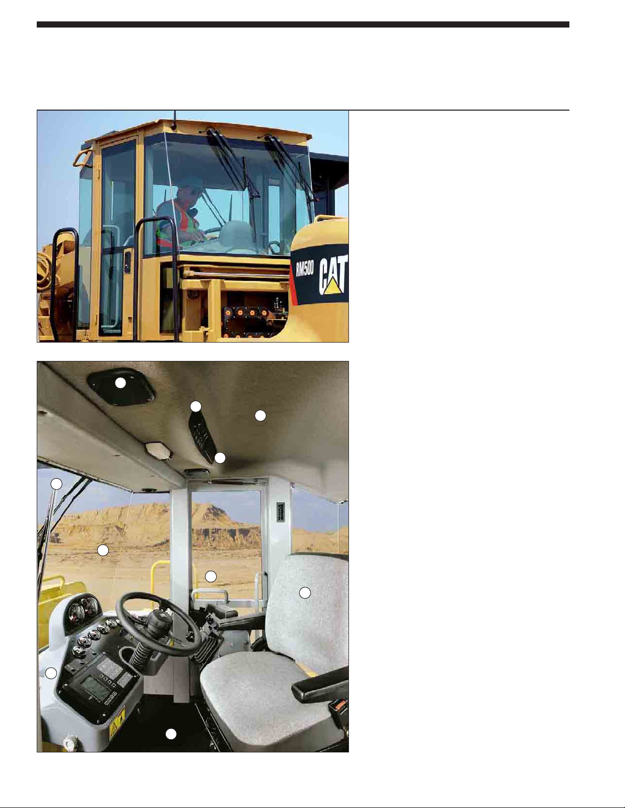
Sliding Cab
Optional cab can increase machine utilization and provides greater year-round comfort in
extreme environment conditions. The cab is fully pressurized and includes air conditioning.
Pressurized iso-mounted cab. Maintains noise,
dust and the elements out, and comfort in.
Fully-equipped cab. Items included with cab are:
rotating cloth seat, left and right side lockable
doors, tinted glass, air conditioning,
heater/defroster, dual front and rear windshield
wipers and sound absorbing floor mat.
Additional operator comforts. The cab also
includes two cup holders and a 12-volt power
receptacle. The cab is also radio-ready and
includes a power converter, antenna with cable,
two speakers and a headliner location for
mounting radio.
Excellent all-round visibility. The cab offers an
exceptional viewing area to the front tire edge,
mixing chamber and to the rear wheels.
The following features further enhance
operator comfort;
1 Heating/air conditioning controls
2 Left and right access doors
3 Rotating cloth seat
4 Sound absorbing headliner
5 Tinted glass
6 Windshield wipers
7 Cushioned floor mat
8 Dual front mounted speakers
9 Radio-ready mount
10 Heavy-duty isolation mounts
1
2
3
4
5
6
7
8
9
10
Page 7
7
Electronic Control Modules
Reliable field-proven technology makes machine operation simple and self-diagnostics
simplifies troubleshooting.
Reliable field-proven technology. Field-proven technology
provides maximum productivity and simplifies
troubleshooting.
Electronic Control Module (ECM). Input signals from sensors
in the engine, propel, steering and rotor drive systems monitor
current operating conditions.
Self-diagnostics. Provides information for troubleshooting
and alerts the operator of potential system problems.
Automatic load control. The load control system
automatically adjusts propel speed so that engine speed does
not drop below 1900 rpm. Machine always works at peak
efficiency for maximum output.
Automatic rotor depth control. Provides consistent quality and
performance.
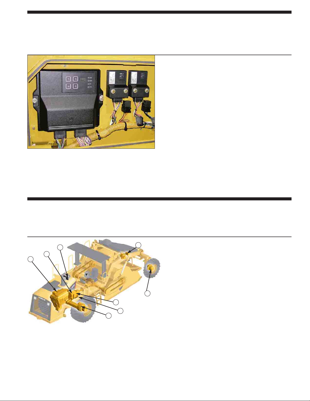
Propel System
Hydrostatic drive provides balanced full-time tractive effort to each drive motor.
1 Caterpillar C15 Engine
2 Electronic Control Modules
3 Front Wheel Propel Pump
4 Front Flow Divider
Control Valve
1
2
3
4
5
6
7
8
5 Front Wheel Drive Motor
6 Rear Wheel Propel Pump
7 Rear Flow Divider
Control Valve
8 Rear Wheel Drive Motor
Optimum tractive effort. The dual propel pumps provide
separate balanced flow to the front and rear dual displacement
drive motors. Superior tractive effort is achieved in soft
underfoot conditions.
Load sensing system. The Electronically Controlled Module
(ECM) matches propel speed to the load on rotor.
Two speed ranges. The machine operates at either maximum
torque to propel the machine through the toughest conditions
or a faster speed for moving around the job site.
Infinitely variable machine speed. The propel lever and speed
dial control infinitely variable machine speed.
Dual flow divider control valves. Equal hydraulic oil flow to
each drive motor increases tractive effort in slippery
conditions.
Page 8
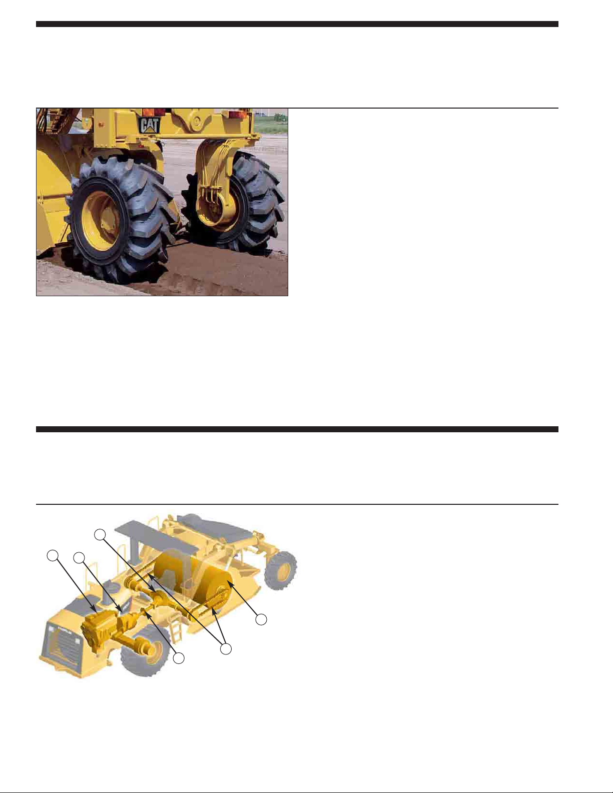
Rotor Drive
Maximum production with high reliability. A Caterpillar powershift transmission provides
three rotor speeds for maximum performance in a variety of materials and cutting depths.
8
Cat powershift transmission. A Cat powershift transmission
drives the rotor and is sized to handle tough cutting and deep
mixing.
Heavy-duty gear reducers. Gear reducers with four planetary
carriers provide excellent rotor drive reliability.
Rotor drive. Rugged drive chains provide efficient, continuous
power to the rotor. Single strand heavy-duty chain resists
breakage. High capacity rotor drive shafts and maintenancefree universal joints.
Three rotor speeds. Three rotor speed selection provides
maximum performance in a variety of materials and cutting
depths. First speed is used primarily for pulverizing the
material. Second and third rotor speeds can be used as
blending or mixing passes.
Heavy-duty shear disc or optional torque limiter. Protects
rotor drive components from torsional stress and shock loads.
All-Wheel-Drive
A separate hydraulic pump provides hydraulic flow to large displacement motors on each
wheel. The system propels the machine with full-time all-wheel drive.
Dual propel pump system. One pump is dedicated to drive the
front wheels, while the second propel pump is dedicated to
drive the rear wheels.
Superior tractive effort. Increased tractive effort for those
tough soil or reclamation jobs.
Flow divider control valve. Equal hydraulic flow to each rear
wheel to provide all-wheel drive.
Four-wheel drive. High torque large displacement motors on
rear wheels makes this a true four-wheel drive machine.
Large rear tyres. Tyres with an aggressive tread and large
footprint propels the machine easily in the most severe
applications.
1 Caterpillar C15 Engine
2 Transmission
3 Axle
1
2
3
4
5
6
4 Rotor
5 Rotor Drive Chains
6 Shear Disc
Page 9
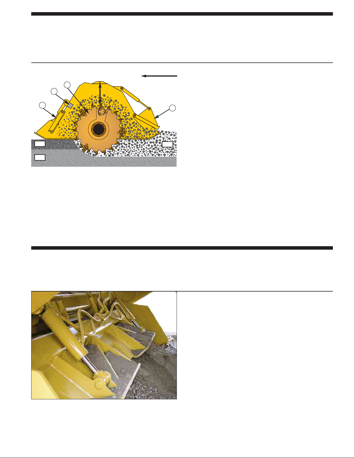
Hydraulic Front Door
Heavy-duty front door is ideal for peak efficiency on soil stabilization, bio-remediation or
mixing passes on asphalt reclamation.
9
Mixing Chamber
Mixing chamber is a heavy-duty hood with large volume to handle deep mixing.
Ensures depth control, proper sizing and thorough blending of reclaimed materials.
Optimum material mixing. The mixing chamber allows the
rotor to move independently so that the capacity of the
chamber actually increases in deeper cuts to allow better
material mixing.
Mid-machine rotor. Total machine weight on rotor helps keep
rotor steady in the cut for uniform depth control.
Increased machine efficiency. Bi-directional mixing
capability increases machine efficiency.
Uniform material sizing. Large heavy-duty breaker bars help
achieve uniform sizing.
Hydraulically adjustable rear door. Provides optimum control
of gradation and material uniformity.
Hydraulically adjustable front door. Allows more precise
sizing control when operating in the reverse direction.
Quick tool replacement. Side access doors enable quick and
simple replacement of cutting tools on rotor ends.
Machine Travel
Rotor Movement
A Asphalt
B Base
R Reclaimed Material
Hydraulically operated front door. Allows the operator to
control the opening of the front door from the operator’s
station.
Precise control. Dual hydraulic cylinders offer increased
lifting force and precise control of the front door. The front
door raises parallel to the cutting surface to prevent the door
from plowing material in harsh soil stabilization conditions.
Increased machine versatility. Forward or reverse operation
increases machine versatility in soil stabilization.
Visual site gauge. The visual site gauge on rotor hood
displays door position and allows the operator to precisely
control the opening of the front door.
B
R
A
1
2
3
4
1 Fully Adjustable Rear Door
2 Universal Rotor (shown)
3 Breaker Bars (if equipped)
4 Fully Adjustable Front Door
Page 10
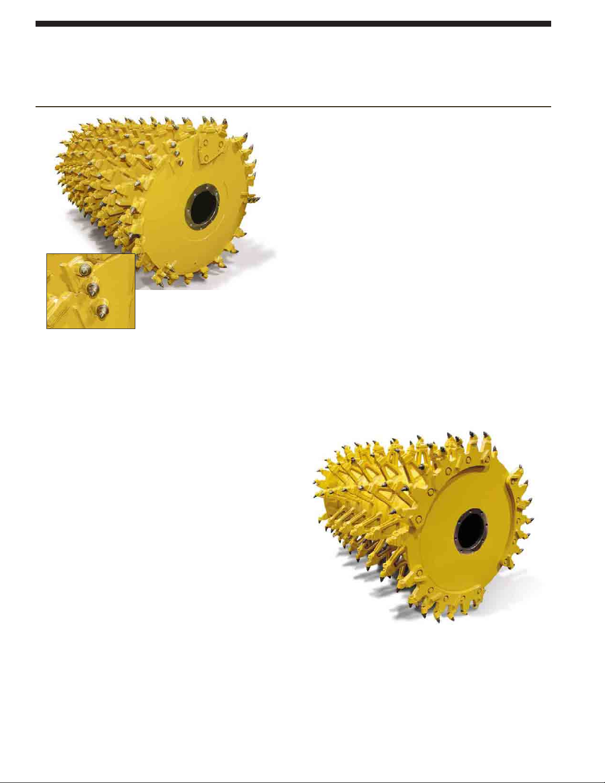
10
Rotor Selection
Choice of two rotor designs for different applications and depth specifications.
Tools are mounted in drive-in, knock-out holders for quick and easy replacement.
Universal Rotor. Designed primarily for use in asphalt
reclamation.
200 point-attack carbide-tipped tools. Tools are mounted
in drive-in, knock-out bolt-on tool holders and arranged in
a chevron pattern for maximum breakout force.
Breakaway design tool holders. Allow for fast
replacement without welding.
Kicker paddles placed on every stand-off. Improves
mixing in soil stabilization and provides more efficient
material movement in full depth reclamation.
Triple-tree tool placement. Tool placement on rotor ends
cleans up loose material and reduces wear on drum when
maneuvering in the cut.
Maximum depth is 457 mm.
Triple-tree tool placement.
Combination Rotor. Designed primarily for use in soil
stabilization with secondary application in light cuts of
asphalt reclamation.
114 point-attack carbide-tipped tools. Tools are mounted
in drive-in, knock-out breakaway bolt-on tool holders.
Versatile applications. Intended for applications where
material gradation is of less importance and where higher
working speeds are desired.
Replaceable end rings. Rotor mandrel are protected from
wear. Rings are hard-faced for extended service.
Maximum depth is 508 mm.
Page 11
11
Serviceability
Less time on maintenance means more time on the job.
Self-lubricating rotor drive chains
in sealed chain cases partially filled
with oil.
Electronic Control Module (ECM). ECM
monitors machine systems and provides
self-diagnostics for operator or service
personnel.
Warnings: Three warning levels alert
operator to conditions on the machine
that require attention. Encourages repair
before major failure.
Level One – a flashing gauge indicator
and a flashing alert indicator light.
Level Two – level one warning plus the
warning action lamp flashing.
Level Three – level two warning plus
the warning action horn sounds.
Visual indicators. Allows easy check of
engine coolant, rotor axle and hydraulic
oil level and air restriction indicator.
Quick-connect hydraulic test ports
simplify system diagnostics.
Ecology drains provide an environmental
method to drain fluids. They are included
on the radiator, engine oil pan, hydraulic
and fuel tank.
S•O•SSMports allow for simple fluid
collection of engine oil, engine coolant
and hydraulic oil.
Secure hose routing. Polyethylene
routing blocks reduce rubbing and
increase service life.
Nylon braided wrap and all-weather
connectors ensure electrical system
integrity. Electrical wiring is colourcoded, numbered and labeled with
component identifiers to simplify
troubleshooting.
Maintenance-free Caterpillar batteries
are mounted on the side of the machine
and are accessible from ground level.
Cat batteries are specifically designed
for maximum cranking power and
protection against vibration.
Machine is Product Link wire-ready.
The Caterpillar Product Link System
(CPLS) ensures maximum uptime and
minimum repair costs by simplifying
tracking of equipment fleets. Provides
automatic machine location and hour
updates. Can be obtained through your
local Caterpillar dealer.
Large one-piece fiberglass hood tilts
forward for exceptional access to the
engine and cooling package. Daily
service points are accessible from
ground level and are grouped on one
side of the engine. Lower side panels
open wide for even greater access.
Cooling package. A multi-row modular
design, stacked in series provides easy
access for cleaning and service.
A modular stacked cooling system
provides more efficient cooling of
individual systems and makes
replacement and routine cleaning easier.
Electronically controlled on-demand
variable speed cooling fan provides the
lowest overall noise levels and high
ambient operation capability.
Hydraulic rotor hood tilt rotates hood
forward for convenient access to rotor
for inspection and tool maintenance.
Hinged service doors open wide on
sides of engine, rotor hood and on top
deck for access to power train and rotor
drive components.
Page 12
12
RM500 Rotary Mixer specifications
Propel System
Brakes
Primary Brake Features
Closed-loop hydrostatic drive
provides dynamic braking during
normal operation.
Parking Brake Features
Spring-applied/hydraulically-released
multiple disc type brake mounted on
each gear reducer. Secondary brakes
are activated by a button on the
operator’s console, loss of hydraulic
pressure in the brake circuit or when
the engine is shut down.
Propel pumps are destroked when
parking brake is engaged. Propel lever
must be returned to neutral after brake
is released before machine will propel.
Engine
The Caterpillar®C15 engine with
ACERT Technology is a six cylinder,
turbocharged air-to-air after-cooled
diesel engine. The engine meets
European EU Stage IIIA emission
regulations.
Gross Power 2000 rpm
SAE J1995 403 kW/548 hp
Rated Net Power 2000 rpm
ISO 9249 403 kW/548 hp
80/1269/EEC 403 kW/548 hp
Bore 137 mm
Stroke 171 mm
Displacement 15.1 liters
All engine horsepower (hp) are
metric including front page.
The power ratings are tested under
the reference conditions for the
specific standard.
Net power advertised is the power
available at the flywheel when the
engine is equipped with an alternator,
air cleaner, muffler and fan at
minimum speed.
The engine provides a torque of
2356 Nm.
Derating is not required up to an
altitude of 1000 m.
All-wheel-drive is standard to provide
full-time four-wheel drive for increased
tractive effort in all applications.
Features
Front and rear wheels are
hydrostatically driven by two dual
displacement piston-type motors.
A separate variable displacement,
piston-type pump with electronic
displacement control supplies
pressurized flow. Planetary gear
reduction on each front and rear
wheel end.
Drive motors have two swashplate
positions allowing operation at either
maximum torque for work or greater
speed for moving around the job site.
Gear selection controlled electrically
by a two-position switch on the
operator’s console.
Infinitely variable machine speed
and direction of travel controlled by
propel lever.
Speed control dial allows the
operator to set the maximum working
speed so that when the propel lever is
placed in the full forward position,
the machine will return to the pre-set
speed.
Load sensing system, controlled by
Electronic Control Module (ECM),
matches propel speed to load on
the rotor.
Flow divider control valve provides
equal hydraulic oil flow to each drive
motor to increase tractive effort in
slippery conditions. Operator can
activate by a switch on the front
control console.
Max. Speeds (forward and reverse):
Working 3.2 km/h
Roading 9.2 km/h
Electrical
The 24-volt electrical system consists
of two maintenance-free Cat batteries.
Electrical wiring is colour-coded,
numbered, wrapped in vinyl-coated
nylon braid and labeled with component
identifiers. The starting system provides
1365 cold cranking amps (cca). The
system includes a 95-amp alternator.
Frame
Fabricated from heavy gauge steel
plates and structural steel tubing. Frame
joined to rear bolster with welded-in
trunion and spherical plain bearings to
allow rear bolster oscillation of 15°.
Page 13

13
RM500 Rotary Mixer specifications
Rotor Drive System
Operates direct through a Caterpillar
three-speed, powershift transmission.
Features
A choice of three rotor speeds
permits working in a wide range of
materials, depths and applications.
ON/OFF switch controls clutch pack
engagement in transmission. Disctype brake on rotor driveline
activates when switch is in the OFF
position.
Rotor speed selection is controlled
electrically by a three-position switch
on the operator’s console. Speed
selection can be changed during
operation.
Single strand, high strength rotor
drive chains on both sides are
contained in heavy-duty chain cases
partially filled with oil.
Shear disc or optional torque limiter
protect rotor drive components.
Rotor drive Chain
Transmission Mechanical
Clutch Hydraulic
Rotor Speeds at 2000 engine rpm
First 110 rpm
Second 152 rpm
Third 205 rpm
Rotor Depth Control
Automatic rotor height and depth
features electronic over hydraulic
control. ECM controls two doubleacting hydraulic cylinders on sides of
mixing chamber. Actual rotor height
and depth are displayed on the
electronic control panel.
Features
Three-position mode switch allows
rotor depth to be controlled manually
or automatically.
Manual mode controls depth using
the raise/lower switch. Visual depth
gauge easily seen from operator’s
station.
AUTOMATIC mode automatically
controls rotor depth to a preset
cutting depth. Setting cutting depth is
easily accomplished first in manual
mode by a switch on the operator’s
console.
TRAVEL mode selection
automatically raises rotor and hood to
a preset travel height.
Steering
A hydraulic power-assist,steering
system provides four steering modes:
front steer only, crab steer, coordinated
and rear steer only.
Features
Two double-acting steering cylinders
control the front wheels and are
powered by a pressure-compensated,
piston-type pump. One double-acting
steering cylinder is attached to the
rear bolster. Constant pressure is
assured in the steering system.
Switch on operator’s side console
provides rear wheel steering mode.
Steering Modes
Front steer only – controlled by a
hand metering unit, maintained by
closed-loop control. The ECM
automatically aligns rear wheels to
the center position for straight
tracking.
Rear steer – controlled by a toggle
switch, maintained by closed-loop
control.
Crab – front and rear wheels turn
simultaneously in the same direction.
Coordinated – front and rear wheels
turn simultaneously in the opposite
direction.
Switch on operator’s side console
provides four steering modes.
Turning Radius (minimum):
Inside 3700 mm
Rotor Specifications
Cutting width 2438 mm
Cutting depth
Universal 457 mm
Combination 508 mm
Drum diameter
Universal 1525 mm
Combination 1625 mm
Number of tools
Universal 200
Combination 114
Tool spacing (tip)
Universal 15.9 mm
Combination 32 mm
Page 14
14
RM500 Rotary Mixer specifications
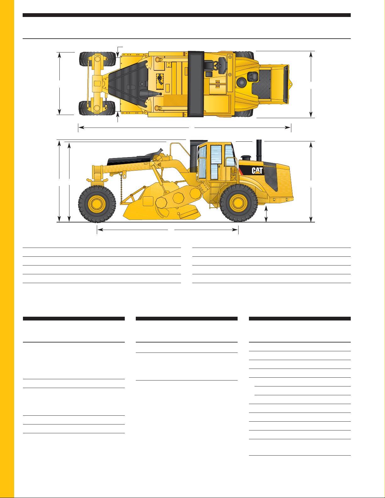
Operating Dimensions
mm
A Overall length 9680
B Overall machine width 2980
C Width at rear wheels 2820
D Rotor hood width 2530
E Height at ROPS 3480
mm
F Height at cab (if equipped) 3390
G Height at handrail 3360
H Wheelbase 6250
I Ground clearance 530
Inside turning radius 3700
RM
500
I
B
F
E
H
C
D
G
A
Operating Weights
Weights shown are approximate and
include coolant, lubricants, 50% fuel
level and a 75 kg operator.
Machine Weights with sliding platform
with universal rotor 27 430 kg
with combination rotor 26 170 kg
Optional Configurations
(add to above figures)
ROPS 512 kg
FOPS 213 kg
Cab 468 kg
Ty re s
Front
26.5” x 25” 20-ply lug-type R-1
3.5 bar
Rear
23.1” x 26” 16-ply lug-type R-1
2.4 bar
Service Refill Capacities
Liters
Fuel tank (useable) 1056
Cooling system 81
Engine oil w/filter 34
Propel planetary gear reducer (each)
Front 5
Rear 4
Hydraulic tank 233
Rotor drive axle 17
Rotor bearing reservoir 2
Chain case (each) 25.6
Rotor drive planetary 3.8
gear reducer (each)
Rotor transmission 12.4
Page 15

15
RM500 Rotary Mixer specifications
Optional Equipment
Some options listed may be an option in some areas and standard in others. Consult your dealer for specifics.
Roll Over Protective Structure (ROPS).
The two-post structure that bolts directly
onto flanges welded to the mainframe.
The structure meets ISO 3471.
The structure can be field installed.
Falling Object Protective Structure
(FOPS). Bolts directly to the ROPS
which provides Level 1 protection and
also serves as a sun canopy. The
structure meets ISO 3449. The structure
can be field installed.
Sliding Cab. includes a rotating cloth
seat, sound absorbing headliner, left and
right side lockable doors, tinted glass, air
conditioning, heater/defroster, dual front
and rear windshield wipers and rubber
floor mat. The cab is also radio-ready
and includes a power converter, antenna
with cable, two speakers and a headliner
location for mounting.
Friction Torque Limiter. Protects rotor
drive train from high torque loads in the
event the rotor strikes an immovable
object. The limiter slips momentarily
without interrupting machine operation.
Roading Light Package. Includes two
front-facing headlights, two amber
running lamps, four amber turn signal/
hazard lamps and a slow moving
vehicle sign. Light package used for
highway transport purposes only.
Warning Beacon Light. Includes an
amber rotating beacon mounted on a
retractable pole and mount.
Mirror Package. Includes an adjustable
mirror mounted on both sides of the
machine for improved visibility to the
rear and along the sides of the machine.
Water Spray System. Accurately adds
water to processed material. System
includes a operator interface panel,
hydraulic filter, EDC controlled
hydraulic pump, a 379 - 1895 liters
per minute vane-type centrifugal pump,
in-line flow meter, spray bar with
nozzles and hydraulically operated
single valve spray bar shut-off.
Universal Rotor. Designed for use
in asphalt reclamation and features
breakaway bolt-on tool holders.
Maximum cutting depth is 457 mm.
Combination Rotor. Designed primarily
for use in soil stabilization with
secondary application in light cuts of
asphalt reclamation and features bolt-on
tool holders. Maximum cutting depth is
508 mm.
Counterweight Kit. A bolt-on weight kit
can be attached to the rear of the
machine. The kit adds stability to the
machine when operating in tough
reclamation jobs exceeding 25 cm of
asphalt.
Page 16

HEHG3417-01 (07/2007) hr
RM500 Rotary Mixer
For more complete information on Cat products, dealer services, and industry solutions, visit us on the web at
www.cat.com
Materials and specifications are subject to change without notice. Featured machines in photos
may include additional equipment. See your Caterpillar dealer for available options.
© 2007 Caterpillar -- All rights reserved
CAT, CATERPILLAR, their respective logos, “Caterpillar Yellow” and the POWEREDGE trade dress as well as
corporate and product identity used herein, are trademarks of Caterpillar and may not be used without permission.
®
 Loading...