

Page 1
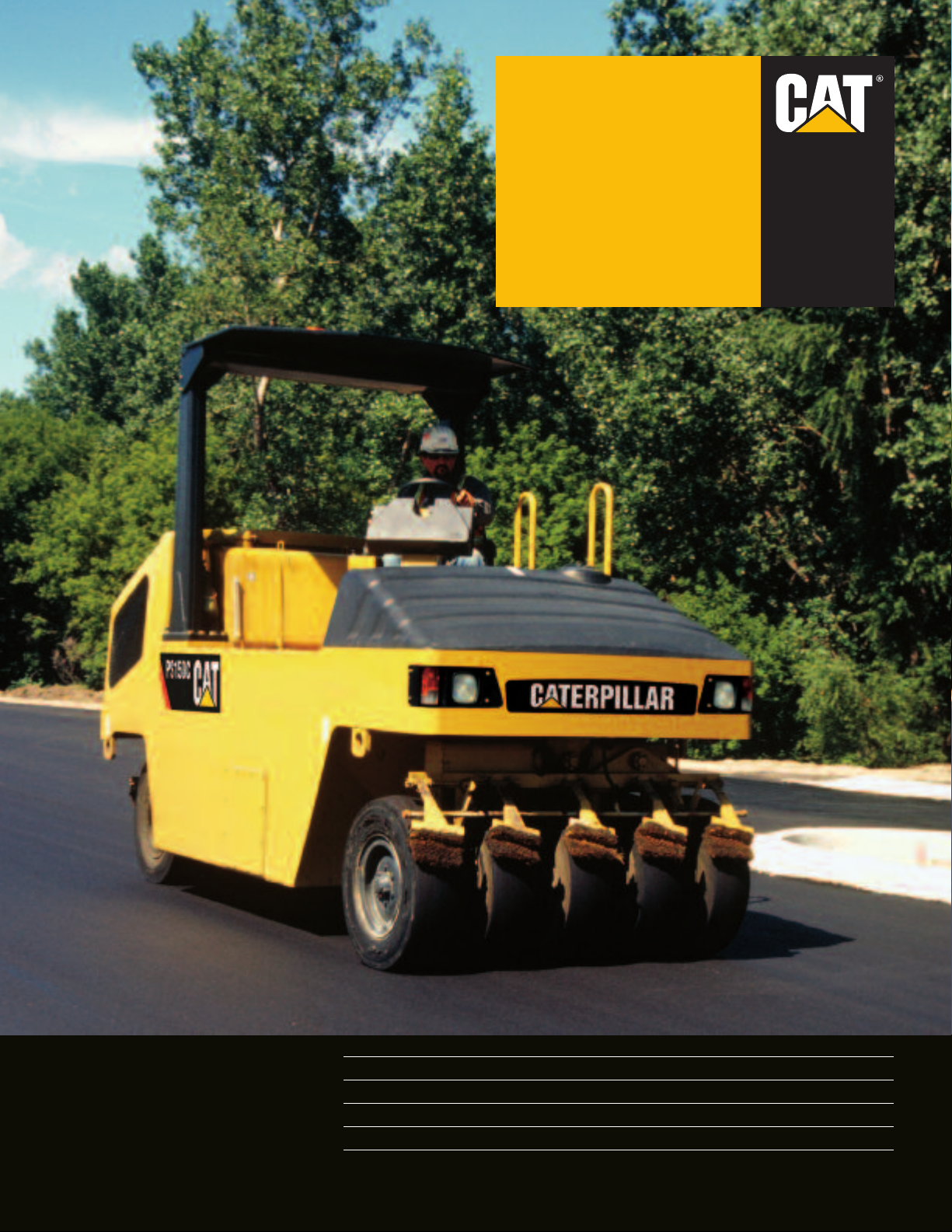
PS150C
Pneumatic
Compactor
Cat®3054C T
Gross Power 75 kW 100 hp
Operating W
Heavy W
Rolling Width 1743 mm 69"
urbochar
eight
eight 17 273 kg 38,000 lb
ged Diesel Engine
12 940 kg
28,535 lb
Page 2
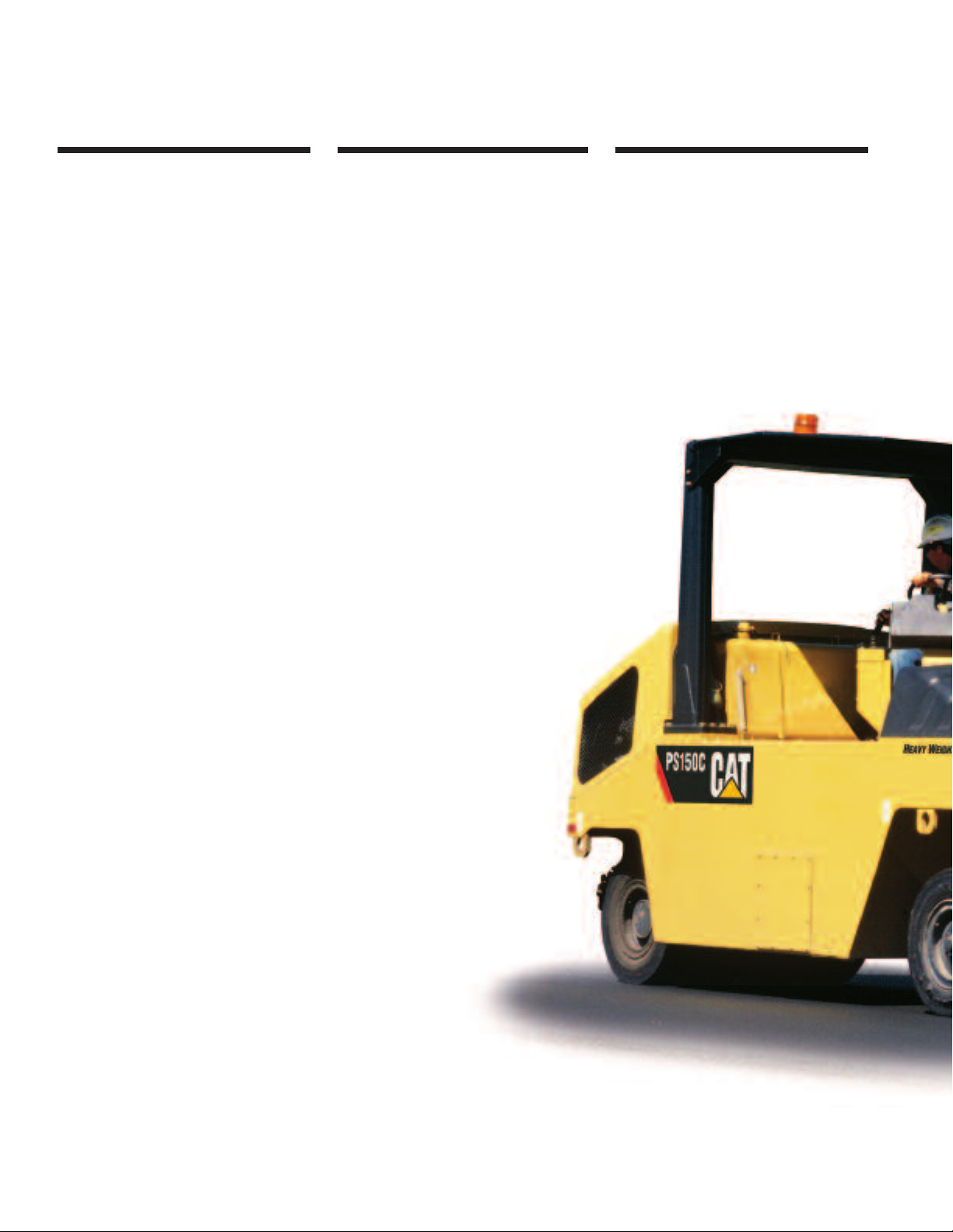
Productivity and Reliability in a Durable Package
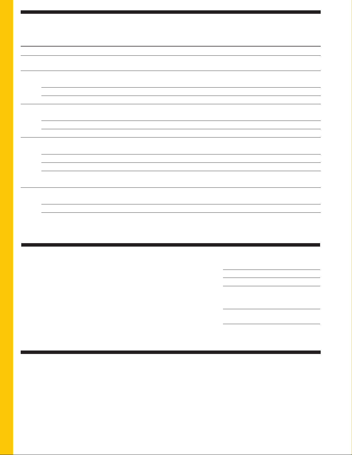
The PS150C Compactor offers high compaction performance, speed
and gradeability to maximize productivity while providing exceptional reliability and durability.
Propel System
Hydrostatic propel system combines
smooth starts and stops with plenty of
torque. The “High Drive” concept does
not use any chains. The drive motors,
secondary brake and hoses are all
protected within the machine frame. The
heavy weight option incorporates
compensating valves
4
motor to increase torque on grades and
increase braking capability.
Page 4
for each propel
4 New feature
load
Engine
Cat®3054C turbocharged diesel engine
4
delivers 75 kW (100 hp) and is built for
performance and reliability without
sacrificing fuel economy.
Page 4
4
Heavy Weight Option
The PS150C offers an optional heavy
weight package that is able to increase
the maximum operating weight to
17 137 kg (38,000 lb). The propel
system includes load compensating
valves that increase torque for higher
speeds and improved braking capability
while working on grades.
Page 6
Performance and reliability you can depend on.
Based upon the industry-proven reputation of the
®
Caterpillar
Compactors, the PS150C establishes new standards
for productivity and reliability in the asphalt
compaction industry.
Durable Cat powertrain, field-proven hydraulic
Systems and the world’s largest and most dedicated
dealer support system ensure the PS150C Asphalt
Compactors will provide maximum utilization.
PS-150B and the PS-200B Asphalt
2
Page 3
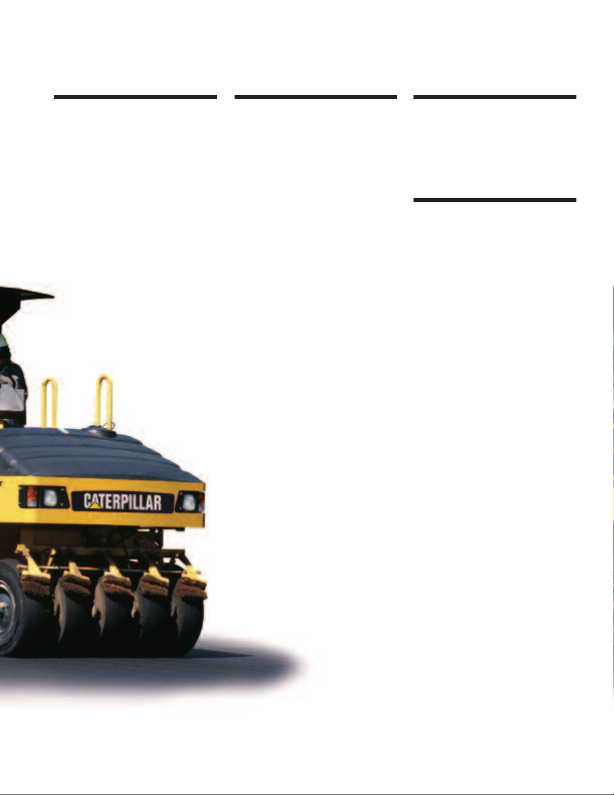
Visibility
The one-piece sloped hood design
provides exceptional operator visibility
to the rear of the machine for improved
safety. The sloped water tank also
provides good visibility to the front of
the machine.
Operator’s Station
The new PS150C Pneumatic
Compactor features excellent operator
omfort and visibility. The propel lever,
c
grouped control gauges and
conveniently located control switches
enhance operator productivity and reduce
fatigue. An optional MVP control
console rotates to three different
positions, left, right or center and
allows the operator to view the front
tire contact points.
Page 5
ersatility
V
The oscillating front and rear wheels
seek out and compact soft spots. The
scillating wheels also provide even
o
wheel loads and uniform compaction
across the rolling width.
Page 5
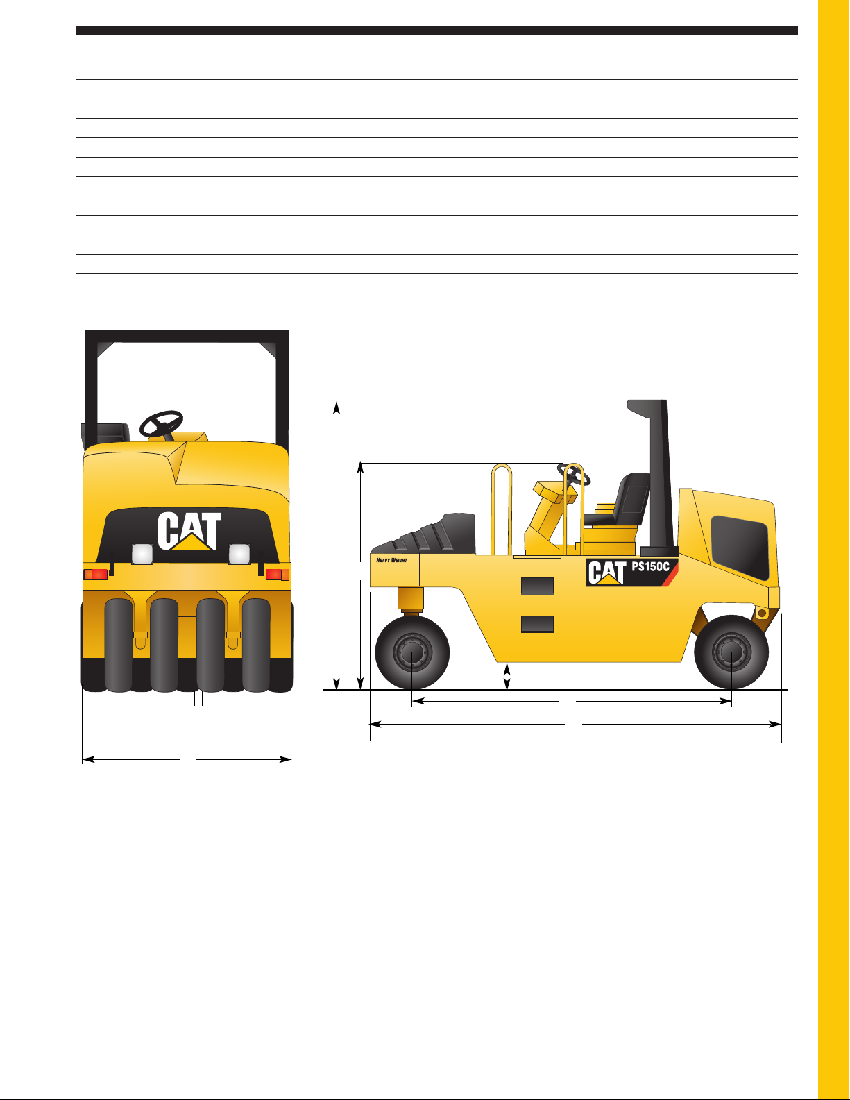
Serviceability
The one-piece fiberglass hood tilts
upward to allow access to the engine
and daily maintenance points. Daily
check points are accessible from ground
The rear mounted cooling system
level.
4
allows easy access for cleaning.
standard oil change interval of 500
hours reduces downtime and
maintenance costs.
Page 6
The
Comfort and serviceability you deserve.
The operator’s station provides a comfortable
and easy-to-use environment that promotes
productive operation. Simplified service
access and extended service intervals
minimizes maintenance time and increases
productive work time.
3
Page 4
R
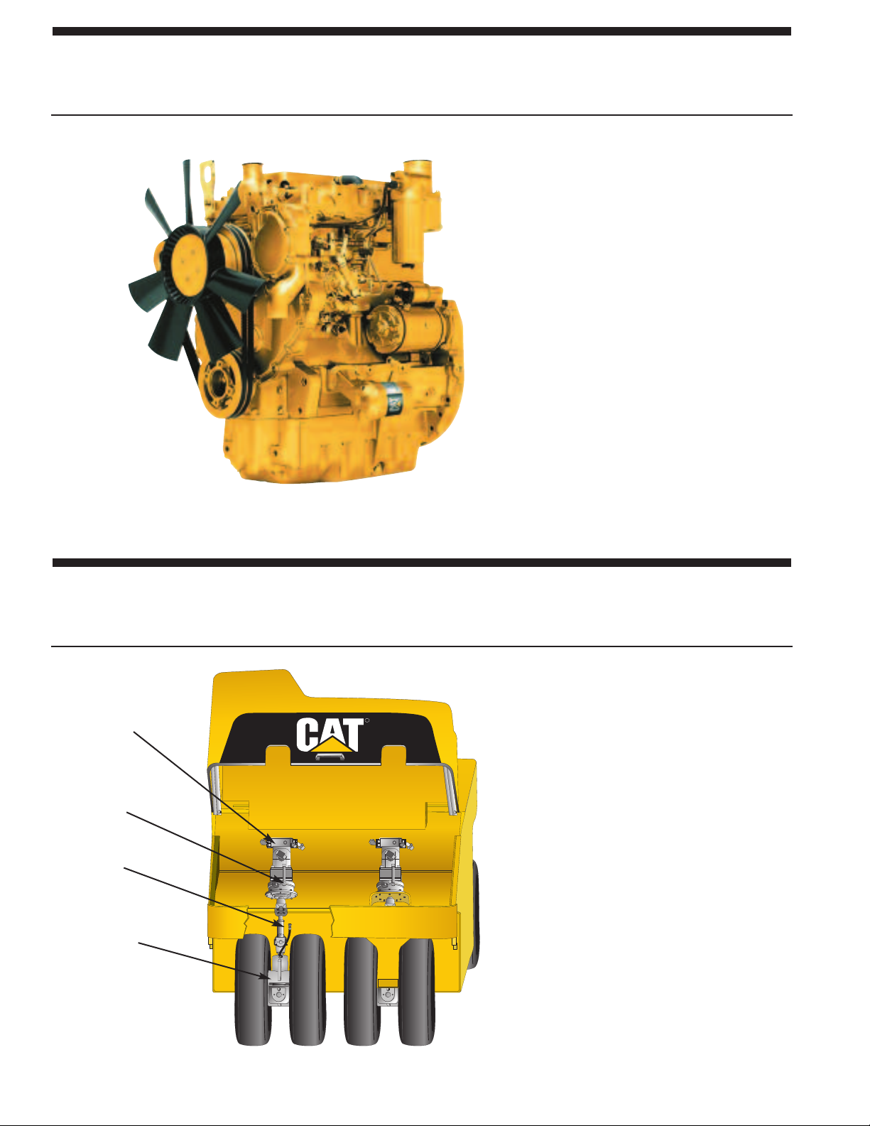
Caterpillar®3054C Turbocharged Diesel Engine
Industry-proven Caterpillar®technology designed to provide unmatched performance,
reliability and fuel economy with ample power for the most demanding jobs.
Turbocharged engine provides 75 kW
100 hp) of gross power. Mechanically
(
controlled direct injection provides
xcellent fuel efficiency.
e
ighly-efficient combustion chamber
H
increases power while lowering fuel
consumption, engine emissions and
noise.
The engine meets
standards.
High displacement-to-power ratio
ensures long life and provides
outstanding reliability and durability.
Large oil cooler reduces oil deterioration
and varnishing of internal components.
500 hour oil change interval is standard.
U.S. Tier 2 emission
Propel System
Hydrostatic propel system combines smooth stops and starts with plenty of torque.
Power transmission with drive line
provides smooth starts and stops – no
chains are used.
q
w
e
r
1 Hydraulic motor
2 Secondary brake
3 Drive line
4 Axle/Planetary drive
Hydrostatic transmission provides
primary braking – no brake shoes or
pads to service.
Easy serviceability to all drive
components.
Hydraulic motors, secondary brakes
and drive lines are positioned high
inside the machine frame, limiting
contamination and damage.
Two speed ranges provide job site
mobility and traction capability to suit
working conditions. Speed ranges can be
shifted while propelling.
Remote drive train flushing system
provides cool hydraulic oil to the brakes
and axles to provide extended drive train
life.
4
Page 5
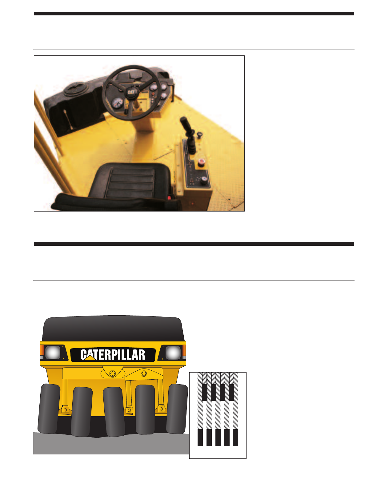
Operator’s Station
Operating ease and comfort promote all-day productivity.
Exceptional all-around visibility
rovides easy maneuvering.
p
Adjustable, cushioned seat provides
asting comfort.
l
Flat platform enhances operator’s
mobility and visibility.
Streamlined gauges keep operator
informed of engine systems and
machine status.
Single lever propel control simplifies
operation.
Standard equipment includes Roll
Over Protective Structure (ROPS) and
75 mm (3") wide retractable seat belt.
Optional rotating operator’s station
allows operator to swivel control
console from left side to right side for
even better visibility.
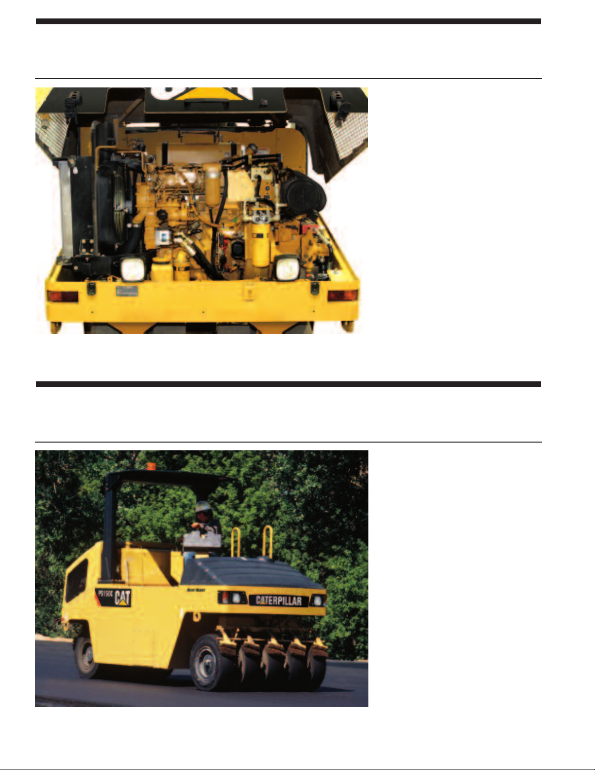
Tire Overlap/Wheel Oscillation
Tires overlap and wheels oscillate for maximum compactive effort with each pass.
Front and rear wheels paths overlap
13 mm (0.5") to provide full-width
coverage of 1743 mm (69") and
2134 mm (84") with 11-wheel option.
Front and rear wheel bolsters oscillate
±4.4 degrees to allow uniform
compaction across entire rolling width.
(Note: With the 11-wheel option,
oscillation angle on outside rear wheels
is 0 degrees up and 4.4 degrees down.)
Wheel oscillation helps ensure
excellent bonding of longitudinal
asphalt joints.
Tire Overlap
5
Page 6
Serviceability
Easy, ground-level access provides convenient and quick service.
Large engine enclosure pivots upward
for access to engine.
Single-point access to all engine
service points and filters is through the
e
Engine access at rear provides oneside, ground level, walk-up service.
Nylon braided wrap and all weather
connectors ensure electrical system
integrity.
Quick-connect hydraulic test ports
simplify system diagnosis.
Remote mounted drains for fuel,
hydraulic and cooling systems allow
collection of fluids.
500 hour oil change interval is standard.
ngine enclosure.
Heavy Weight Option
Provides maximum machine versatility and utilization, while enhancing productivity
Maximum operating weight of
17 137 kg (38,000 lb) increases
versatility for working on thick lifts.
Maximum weight per wheel of 1920 kg
(4,220 lb) provides increased ground
contact pressures for thick lifts and
harsh mixes.
Ballast (optional) provides an additional
6168 kg (13,600 lb) of steel ballast for
increased versatility.
Load compensating valves provide
increased torque to the propel motors
for working on grades and on tough
underfoot conditions.
Maximum travel speed of 25.6 km/h
(15.9 mph) provides quick
maneuverability around the job site.
12-ply tir
weight option.
6
es
are standard with the heavy
Page 7

Engine
Four-stroke cycle, four cylinder 3054C
turbocharged diesel engine. The engine
meets U.S. EPA Tier 2 emissions
regulations.
Ratings at RPM kW hp
Gross power 2200 75 100
Ratings of Caterpillar®machine engines
are based on standard air conditions of
25°C (77°F) and 99 kPa (29.32") Hg
dry barometer. Power is based on using
35° API gravity fuel having an LHV of
42,780 kJ,kg (18,390 Btu/lb) when
used at 30°C (86°F) [ref. a fuel density
of 838.9 g/L (7.001 lb/U.S. gal)]. Net
power advertised is the power available
at the flywheel when the engine is
equipped with fan, air cleaner, muffler
and alternator.
The following ratings apply at 2,200
RPM when tested under the specified
standard conditions for the specified
standard:
Net Power kW hp
ISO 9249 72 96
SAE J1349 72 96
EEC80/1269 72 96
Transmission
Two-speed hydrostatic propel system.
ydrostatic pump provides oil to two
H
hydrostatic motors mounted above the
drive axles. Drive shafts connect the
motors to the rear axles.
single propel lever located on the
A
control console provides smooth
hydrostatic control of the infinitely
variable speeds in both forward and
reverse.
Speed (forward and reverse):
Low 0 - 11 km/h (6.8 mph)
High 0 - 18.5 km/h (11.5 mph)
Wheels and Tires
6-Ply: 8.50/90 x 15
5 wheels front, 4 wheels rear
11-wheel option
6-Ply: 8.50/90 x 15
Brakes
ervice brake features
S
losed-loop hydrostatic drive system
C
provides dynamic braking during
machine operation.
Secondary brake features*
Spring-applied/hydraulically released disc
brakes are actuated by a switch on the
control console. They are also activated
automatically if pressure is lost in the
brake circuit or when the engine is shut
off.
*Brake systems meet SAE standard J1472 and EN500-4.
Axles
Tractive effort is delivered to the four
rear drive wheels by standard, heavyduty axles.
Dimensions
Bore 105 mm 4.13"
Stroke 127 mm 5"
Displacement 4.4 L 269 cu. in.
Dual-element, dry-type air cleaner with
visual restriction indicator.
Electrical System
24-volt electrical system includes two
maintenance-free Cat®batteries, colorcoded and numbered wiring wrapped in
nylon braid. A
powers the electrical system.
55-amp alternator
PS150C specifications
7
Page 8

Steering
Steering is hydraulic power-assist for
esponsive, low-effort machine handling.
r
Minimum turning radius:
Inside 4648 mm (15' 3")
utside 6453 mm (21' 2")
O
Steering angle (each direction) 37.5°
Hydraulic system – one 75 mm (3")
bore, double-acting cylinder powered by
a gear pump.
Frame
Frame is fabricated from welded heavy-
auge steel plates. Integral baffle plates
g
prevent water surge when water
ballasted. Ballast compartments have
cover plates. Frame design provides a
calculated balance of wheel to weight
atio for even distribution of ballast
r
weight.
The clean, unitized design provides a
flat deck for excellent operator mobility.
The frame is designed for easy access to
all major components.
Instrumentation and
Gauges
he start switch, engine throttle switch,
T
alternator indicator light, coolant
temperature gauge, engine oil pressure
gauge, hydraulic oil temperature gauge
and hour meter are located on the
nstrument panel in front of the
i
operator.
Machine instrumentation and most
controls are located at the operator’s
right on the control console. This
includes the propel lever, speed selector
switch, water system control, horn and
secondary brake switch.
Service Refill Capacities
U.S.
Liters Gallons
Fuel tank* 173 45.6
Cooling system 16,1 4.2
Engine oil (w/filter) 7,3 1.9
Brake 0,3 0.08
Axle 2,7 0.71
Hydraulic tank 54,9 14.5
Water (spray) tank 394 104
*Note: Actual fuel tank capacity is 162 L (42.8 gal).
Water System
The gravity water system is efficient
and reliable. System includes galvanized
distribution bars over the front and rear
tires and retractable nylon tire scrapers
for each tire.
A polyethylene water tank is located at
the front of the machine on the
operator’s platform. A water level gauge
is on the tank within easy sight of the
operator.
Pressurized water system is optional.
Operator and Machine
Protective Equipment
The Roll Over Protective Structure
(ROPS) is a two-post structure that
bolts directly onto flanges welded to the
machine frame. The structure meets
SAE J231, SAE J1040, ISO 3449 and
ISO 3471.
Backup alarm emits a 107 dB(A) alarm
whenever the machine is in reverse. The
backup alarm is standard equipment.
Retractable seat belt is 76 mm (3")
wide and is standard equipment.
8
PS150C specifications
Page 9
Dimensions
PS150C w/11-wheel option
A Length 4.29 m 14' 1" 4.29 m 14' 1"
B Compaction width 1.74 m 5' 8" 2.13 m 6' 11"
Height at steering wheel 2.32 m 7' 7" 2.32 m 7' 7"
C
D Height at ROPS 3.0 m 9' 10" 3.0 m 9' 10"
E Wheel base 3.34 m 10' 11" 3.34 m 10' 11"
F Ground clearance 267 mm 10.5" 267 mm 10.5"
G Tire overlap 13 mm 0.5" 13 mm 0.5"
Outside turning radius 6.45 m 21' 2" 6.45 m 21' 2"
Inside turning radius 4.64 m 15' 3" 4.44 m 14' 7"
Oscillation angle ±4.4 degrees ±4.4 degrees*
Oscillation angle for outside rear wheels is 0 degrees up and 4.4 degrees down.
*
D
C
F
E
G
B
A
PS150C specifications
9
Page 10
Weights (approximate)
perating weights include lubricants, coolant, 80 kg (175 lb) operator, full fuel tank, full hydraulic system, half-full water tank
O
and ROPS.
Operating Weights
Model Condition Weight of Ballast Total Weight Average Weight pe
heel
W
PS150C
Standard machine empty — — 4885 kg 10,775 lb 545 kg 1,200 lb
Maximum water ballast 3825 kg 8,430 lb 8710 kg 19,205 lb 970 kg 2,145 lb
Maximum wet sand ballast 8055 kg 17,760 lb 12 940 kg 28,535 lb 1440 kg 3,180 lb
S150C w/11-Wheel Option
P
Standard machine empty — — 4955 kg 10,925 lb 450 kg 993 lb
Maximum water ballast 3825 kg 8,430 lb 8780 kg 19,355 lb 798 kg 1,760 lb
Maximum wet sand ballast 8055 kg 17,760 lb 13 010 kg 28,685 lb 1183 kg 2,608 lb
PS150C w/Heavy Weight Option
Standard machine empty — — 4955 kg 10,925 lb 551 kg 1,214 lb
Maximum water ballast 3825 kg 8,430 lb 8780 kg 19,355 lb 970 kg 2,145 lb
Maximum wet sand ballast 8055 kg 17,760 lb 13 010 kg 28,685 lb 1440 kg 3,180 lb
With 12 307 kg (27,075 lb)12 307 kg 27,075 lb 17 273 kg 38,000 lb 1920 kg 4,222 lb
Iron and wet sand ballast
PS150C w/Heavy Weight Option and 11-Wheel Option
Standard machine empty — — 5025 kg 11,078 lb 457 kg 1,008 lb
Maximum water ballast 3825 kg 8,430 lb 8850 kg 19, 511 lb 805 kg 1,775 lb
Maximum wet sand ballast 8055 kg 17,760 lb 13 080 kg 28,836 lb 1189 kg 2,621 lb
Ballast Compartments
Ballast compartments are positioned with
a calculated balance of wheel to weight
ratio. Internal-frame baffles help prevent
surges when water ballasted.
Sand and steel ballast can be added
through lar
ge cover plates on the
operation deck and water can be added
through a fill port. When adding water, it
is recommended that only the primary
ballast chamber be used because it is
sealed.
Sand and steel ballast can be removed
through a bolt-on side cover and water
ballast can be emptied through a drain
port.
Ballast Considerations and Ground Contact Pressures
The most common method of changing
ground contact pressure is to vary the
tire pressure. Another means to change
ground contact pressure is to alter the
ballast. The PS150C can be ballasted
with sand, water, steel or a combination
of each. These three components provide
varying weight capacities, allowing the
Ballast Capacities
Primary 3,9 m3(139 ft3)
Secondary 0,4 m3(11 ft3)
Total 4,3 m3(150 ft3)
Ballast Materials
0,028 m3(1 ft3) of wet sand weighs 57 kg (125
lb)
0,028 m3(1 ft3) of water weighs 28 kg
(62.4 lb)
machines to be tailored to specific
requirements.
10
PS150C specifications
Page 11

Average Ground Contact Pressures
Actual Ground Contact Pressures are measured across the width of the tire. The charts include wheel path overlap.
Tire Ply
Ti re kPa
ressure
P
p
Wheel Load
GCP kPa
545 kg psi
1,200 lb CA cm
i
GCP kPa
970 kg psi
2,145 lb CA cm
in
GCP kPa
1440 kg psi
3,180 lb CA cm
in
GCP kPa
1920 kg psi
4,220 lb CA cm
in
6-Ply 12-Ply 14-Ply
8.50/90 x 15
7.50 x 15 7.50 x 15
Smooth Tires Smooth Tires Smooth Tires
275 344 344 413 482 550 619 688 757 344 413 482 550 619 688 757 826 862
40 50 50 60 70 80 90 100 110 50 60 70 80 90 100 110 120 125
si
round Contact Pressures (GCP) and Contact Areas (CA)
G
162 183 236 266 284 306 317 317 344 243 266 284 295 317 330 344 359 367
24 27 34 39 41 44 46 46 50 35 39 41 43 46 48 50 52 53
2
329 291 226 200 187 174 168 168 155 220 200 187 181 168 162 155 149 145
2
1 45 35 31 29 27 26 26 24 34 31 29 28 26 25 24 23 22
5
n
197 214 250 284 314 343 369 378 410 259 295 321 343 369 388 410 421 427
29 31 36 41 46 50 54 55 60 38 43 47 50 54 56 60 61 62
2
485 446 381 336 304 278 258 252 233 368 323 297 278 258 245 233 226 223
2
75 69 59 52 47 43 40 39 36 57 50 46 43 40 38 36 35 34
235 254 280 304 331 358 390 405 607 273 312 336 364 390 413 437 465 475
34 37 41 44 48 52 57 59 88 40 45 49 53 57 60 64 68 69
2
601 556 504 465 426 394 362 349 233 517 452 420 388 362 342 323 304 297
2
93 86 78 72 66 61 56 54 36 80 70 65 60 56 53 50 47 46
— — 296 319 346 368 387 403 440 309 319 341 354 372 387 403 414 417
— — 43 47 50 53 56 59 64 45 47 49 51 54 56 59 60 61
2
— — 601 559 516 485 461 442 405 577 559 522 504 479 461 442 429 427
2
— — 93 86 80 75 71 68 63 89 86 81 78 74 71 68 67 66
PS150C specifications
11
Page 12
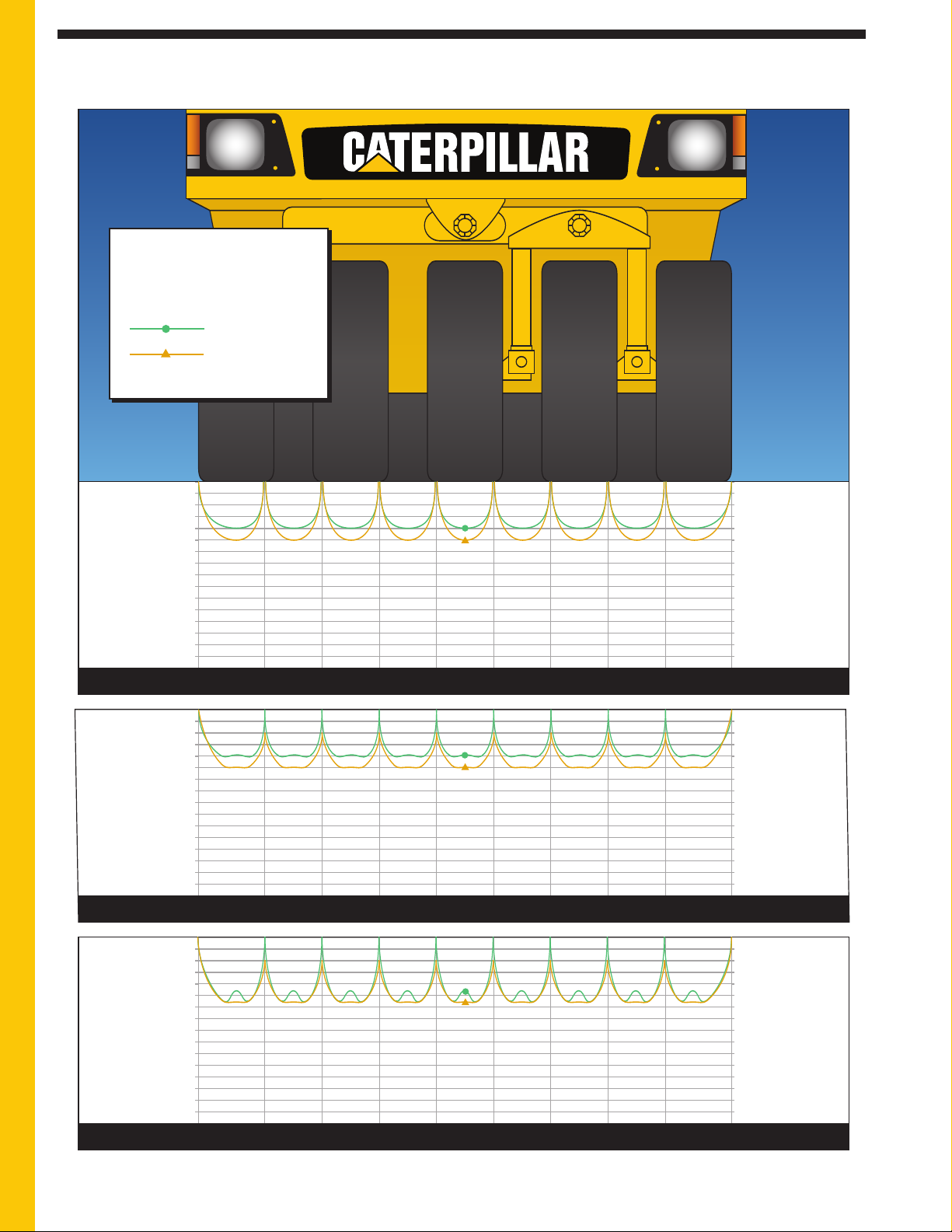
Actual Ground Contact Pressures for 6-Ply: 8.50/90 x 15 Tires
Tire Inflation
Pressures
0
1
0
20
3
0
4
0
5
0
110
120
130
140
150
60
70
80
90
100
0
6
9
0 0
69
0 0
69
138
2
07
2
76
3
45
758
827
896
965
1034
414
483
552
621
689
545 kg (1,200 lb) Wheel Load – Standard machine empty
Ground Contact
Pressures (psi)
Ground Contact
Pressures (kPa)
10
20
30
40
50
110
120
130
140
150
60
70
80
90
100
138
207
276
345
758
827
896
965
1034
414
483
552
621
689
970 kg (2,145 lb) Wheel Load – Maximum water ballast
Ground Contact
Pressures (psi)
Ground Contact
Pressures (kPa)
10
20
30
40
50
110
120
130
140
150
60
70
80
90
100
138
207
276
345
758
827
896
965
1034
414
483
552
621
689
1440 kg (3,180 lb) Wheel Load – Maximum wet sand ballast
Ground Contact
Pressures (psi)
Ground Contact
Pressures (kPa)
275 kPa (40 psi)
344 kPa (50 psi)
Actual Ground Contact Pressures are measured across the width of the tire. The charts include wheel path overlap.
12
PS150C specifications
Page 13
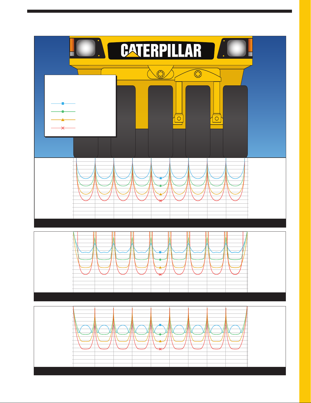
Actual Ground Contact Pressures for 12-Ply: 7.50 x 15 Tires
276 kPa (40 psi)
345 kPa (50 psi)
414 kPa (60 psi)
344 kPa (50 psi)
482 kPa (70 psi)
619 kPa (90 psi)
757 kPa (110 psi)
Tire Inflation
Pressures
0
0
69
10
20
30
40
5
0
110
120
130
140
150
60
7
0
80
90
100
138
207
276
3
45
758
827
896
965
1034
414
4
83
552
621
689
970 kg (2,145 lb) Wheel Load – Maximum water ballast
Ground Contact
Pressures (psi)
Ground Contact
Pressures (kPa)
0
10
20
30
40
50
110
120
130
140
150
60
70
80
90
100
0
69
0 0
69
138
207
276
345
758
827
896
965
1034
414
483
552
621
689
1440 kg (3,180 lb) Wheel Load – Maximum wet sand ballast
Ground Contact
Pressures (psi)
Ground Contact
Pressures (kPa)
10
20
30
40
50
110
120
130
140
150
60
70
80
90
100
138
207
276
345
758
827
896
965
1034
414
483
552
621
689
1920 kg (4,220 lb) Wheel Load – Maximum iron and wet sand ballast, PS150C w/Heavy Weight
Ground Contact
Pressures (psi)
Ground Contact
Pressures (kPa)
Actual Ground Contact Pressures are measured across the width of the tire. The charts include wheel path overlap.
PS150C specifications
13
Page 14
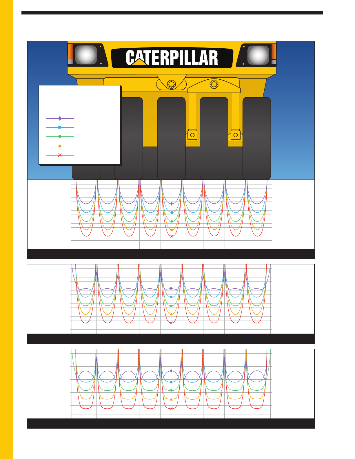
Actual Ground Contact Pressures for 14-Ply: 7.50 x 15 Tires
276 kPa (40 psi)
345 kPa (50 psi)
414 kPa (60 psi)
0 0
69
10
20
30
40
5
0
110
120
130
140
150
60
7
0
80
90
100
138
207
276
3
45
758
827
896
965
1034
414
4
83
552
621
689
970 kg (2,145 lb) Wheel Load – Maximum water ballast
Ground Contact
Pressures (psi)
Ground Contact
Pressures (kPa)
344 kPa (50 psi)
482 kPa (70 psi)
619 kPa (90 psi)
757 kPa (110 psi)
Tire Inflation
Pressures
862 kPa (125 psi)
0
20
30
40
50
110
120
130
140
150
60
70
80
90
100
0
69
138
207
276
345
758
827
896
965
1034
414
483
552
621
689
1440 kg (3,180 lb) Wheel Load – Maximum wet sand ballast
Ground Contact
Pressures (psi)
Ground Contact
Pressures (kPa)
10
0 0
6910
20
30
40
50
110
120
130
140
150
60
70
80
90
100
138
207
276
345
758
827
896
965
1034
414
483
552
621
689
1920 kg (4,220 lb) Wheel Load – Maximum iron and wet sand ballast, PS150C w/Heavy Weight
Ground Contact
Pressures (psi)
Ground Contact
Pressures (kPa)
Actual Ground Contact Pressures are measured across the width of the tire. The charts include wheel path overlap.
14
PS150C specifications
Page 15

Optional Equipment
ote: Standard and optional equipment may vary. Consult your Caterpillar
N
®
ealer for specifics.
d
The Speedometer is calibrated in both
ilometers per hour and miles per hour
k
on an analog dial.
Pressure Water Spray System
provides constant water spray regardless
of the tank level or when working on
grades.
12-Ply or 14-Ply Tires with higher
tire pressures and increased ground
contact pressure provide greater
compactive effort.
Radial Tires (7.50 x 15) ensure a
flat contact area, regardless of the tire
load or inflation pressure.
Heat Retention Shields (Tire
Skirts) trap heat and help prevent
asphalt from adhering to the tire
surfaces.
11 Wheels Option add two wheels to
he rear axle. This option is only
t
intended for chip and seal applications
and cannot be used in conjunction with
the ballast option.
Roading Light Package consists of
front and rear floodlights, tailights and
parking lights with flashers.
Rotating Operator’s Station with
Maximum Visibility Position (MVP)
control console pivots to three locked
positions – left, center and right.
Suspension Seat is mechanical type
with vertical adjustment and armrests.
Sun Canopy is a sheet-metal structure
that blocks the operator’s station from
the sun. The structure is bolted to the
ROPS.
Traction Control consists of a foot
ctivated control switch that activates a
a
hydraulic oil flow divider for increased
tractive effort.
Heavy Weight Option increases
weight capacity to 17 273 kg (38,000)
and includes load sensing valves for each
propel motor to increase torque for
braking and working on grades.
Ballast Option provides an additional
6168 kg (13,600 lb) of steel ballast for
use with the heavy weight option.
Total Customer Support System
Parts availability—most parts on dealer’s shelf when you need them. Computer-controlled, emergency search system backup.
Parts stock lists—dealer helps you plan on-site parts stock to minimize your parts investment while maximizing machine
availability.
Service capability—dealer’s shop or fast field service by trained technicians using latest tools and technology.
Machine management services—ef
fective preventive maintenance programs, cost-ef
meetings, operator and mechanic training.
Literature support—easy-to-use parts books, operation and maintenance manuals, and service manuals help you get
maximum value from equipment.
Flexible financing—your dealer can arrange attractive financing on the entire line of Caterpillar equipment. Terms structured
to meet cash flow requirements. See how easy it is to own, lease or rent Cat equipment.
fective repair options, customer
15
Page 16
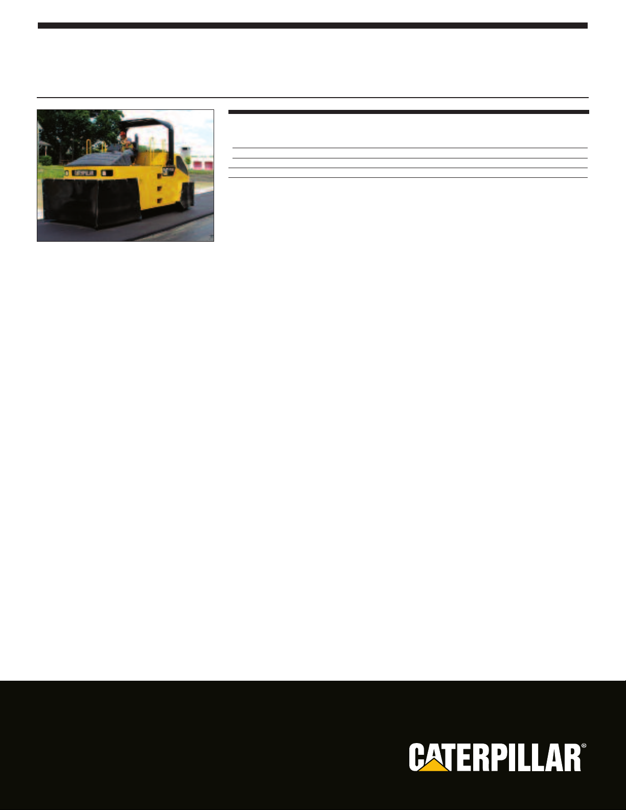
Caterpillar offers a comprehensive line of pneumatic tire compactors.
Contact your local Caterpillar dealer to learn more about the complete line of Caterpillar
Paving Products.
PS360C Pneumatic Compactor
Operating Weight
Standard Machine 8500 kg 18,740 lb
Maximum Ballast 25 000 kg 55,115 lb
Rolling Width 2.28 m 7' 6"
Gross Power 98 kW 130 hp
QEHQ1075-02 (06/10)
© 2010 Caterpillar
All Rights Reserved.
www.cat.com
.COM
T
.CA
SAFETY
Featured machines in photography may include optional equipment.
Materials and specifications are subject to change without notice.
CAT, CATERPILLAR, their respective logos, “Caterpillar Yellow” and the POWER EDGE trade dress, as well as corporate and
oduct identity used her
pr
ein, are trademarks of Caterpillar and may not be used without permission.
TM
 Loading...