

Page 1
AP-500
INDEX
JAN. 2007
AP-500
ELECTRONIC KEYBOARD
Page 2

CONTENTS
Specifications ---------------------------------------------------------------------------------------------- 1
Block Diagrams-------------------------------------------------------------------------------------------- 2
Circuit Description --------------------------------------------------------------------------------------- 3
Printed Circuit Board ------------------------------------------------------------------------------------ 5
Disassembly ------------------------------------------------------------------------------------------------ 9
Diagnostic Program ------------------------------------------------------------------------------------ 17
Exploded View ------------------------------------------------------------------------------------------- 21
Parts List--------------------------------------------------------------------------------------------------- 23
Schematic Diagrams ----------------------------------------------------------------------------------- 28
Page 3

SPECIFICATIONS
GENERAL
Keyboard 88-key piano keyboard, with Touch Response
Maximum Polyphony 128 notes
Tones 164 (with Layer and Split)
Effects DSP, Reverb (4 types), chorus (4 types), Acoustic Resonance, Brilliance (-3 to -1, 1 to 3)
Metronome • Beats: 0, 2, 3, 4, 5, 6
• Tempo Range: 20 to 255
Demo Songs • Number of Songs: 74 songs (All-song repeat play)
Music Library • Number of Songs: 60
User Songs: Up to 10
(Up to approximately 3.1 MB; up to approximately 318 KB per song)*
* Based on 1 KB = 1024 bytes, 1 MB = 10242 bytes.
• Song volume: Adjustable
• Part On/Off: L, R
Recorder • Functions: Real-time recording, playback
• Number of Songs: 5
• Number of Tracks: 2
• Capacity: Approximately 50,000 notes total
(Up to approximately 10,000 notes per song)
• Recorded Data Protection: Built-in flash memory
Pedals Damper, soft, sostenuto
Other Functions • Touch Select: 3 types, Off
• Transpose: 1 octave (-6 to 0 to 5)
• Tuning: A4 = 440.0 Hz ±50 cents (variable)
MIDI 16-channel multi-timbre receive
SD Memory Card • SD memory card slot
• Supported SD Memory Cards: Up to 1 GB (Larger capacity cards not supported.)
• Functions: SMF playback, data storage, data recall, card format
Inputs/Outputs • PHONES jack: Stereo standard jacks ✕ 2
• MIDI THRU/OUT/IN terminals
• LINE IN R, L/MONO jacks: Standard jacks ✕ 2
Input impedance: 7.0KΩ
Input Voltage: 290mV (RMS)
• LINE OUT R, L/MONO jacks: Standard jacks ✕ 2
Output impedance: 1.1KΩ
Output Voltage: 2.3V (RMS) MAX
• USB port: Type B
• Pedal connector
Speakers ø16cm ✕ 2 + ø5cm ✕ 2 (Output 30W + 30W)
Power Requirements AP-500: 120V
AP-500V: 220-240V
Power Consumption AP-500: 78W
AP-500V: 78W
Dimensions Digital Piano and Stand: 138.1 (W) ✕ 47.3 (D) ✕ 87.4 (H) cm
(54 7/16 ✕ 18 10/16 ✕ 34 7/16 inch)
Weight Digital Piano and Stand: approximately 53.0kg (116.8 lbs)
• Specifications and designs are subject to change without notice.
• The power cord of the AP-500 is hard-wired to the digital piano.
• The power cord of the AP-500V is detachable.
— 1 —
Page 4
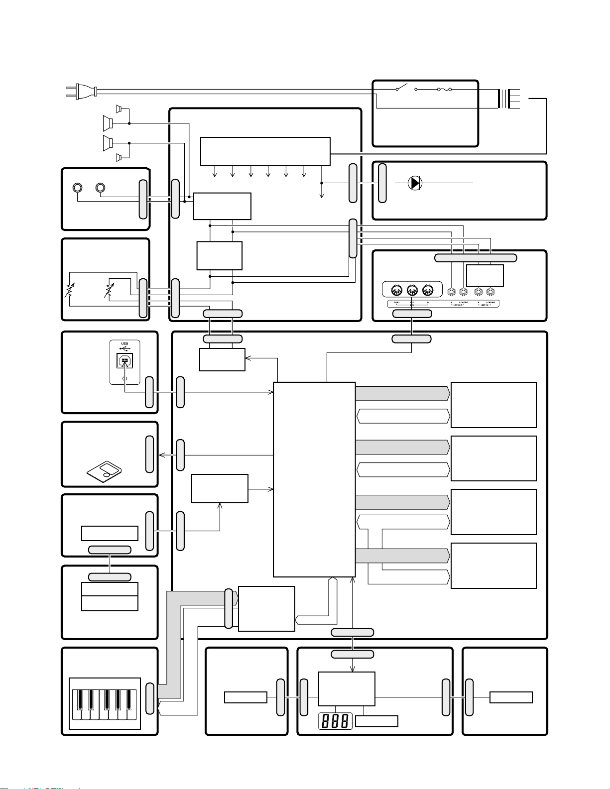
BLOCK DIAGRAM
TWEETER (R)
(R)
SPEAKERS
(L)
TWEETER (L)
Phones
L R
JACK PCB
(M332-JKA2)
VOLUME PCB
(M332-JKA3)
Main
Volume
CN403
CN404
SUB PCB (M332PSA1)
Power Supply Circuit
IC201, D211~D216, C209, 211, 212,
215, 217, 219, 220, 225, 229
VFVCVD18 VA12 VE5VA18
Power Amplifier
CN207
CN216
IC202
STK402-070
Filter
IC205
NJM2068M
CN220
CN1
CN1
IC10
CS4351
D00
BCK
WCK
SYSCK
VD5
Power Switch
POWER SUPPLY PCB
(M332-ACA1)
CN406
CN206CN217
JACK PCB
(M332-JKA1)
CN402
CN3
Fuse
FU1
Power LED
POWER LED PCB
CN1
Filter
IC401
NJM2068D
(M408-MDA1)
Transformer
T1
(M332-JKA5)
MAIN PCB
USB PCB
(M332-JKA4)
SD CARD PCB
(M332-SDA1)
Smart media Unit
PEDAL PCB
(M332-PDA2)
DAMPER
CN2
CN3
SOFT
SOSTENUTO
PEDAL PCB
(M332-PDA1)
KEYBOARD PCBs
(MCPZ-KYA/KYB)
Keyboard
C405
CN751
CN1
CN803
CN9 CN7
IC9
74VHC541
CN11
KC0 ~ KC7
SI0 ~ SI10,
FI0, FI10
CONSOLE PCB
(M332-CNB2)
SOFT
SOSTENUTO
DAMPER
KEYBORD
CONTROLLER
IC11
CN14
uPD65942GA
Buttons
MPU
IC5
MB91F036PFF
CK12M
RSTB
SIN2
SOOT2
CN604
CN602
TXDO
TXDI
CN4
CN600
IC601
uPD65881GK
SDA0 ~ SDA11, BA0, BA1
SDD0 ~ SDD15
EA0 ~ EA16
EA0 ~ ED7
Control signal
D8 ~ D15
A1 ~ A20
D0 ~ D15
CONSOLE PCB
(M332-CNA1)
Buttons
RAM (128Mbit)
IC2
EDS1216AATA
RAM (1Mbit)
IC3
CY62128DV30LL
NAND FLASH (256Mbit)
IC6
NAND256W3A2BN
RAM (16Mbit)
IC7
MB82D01181E60L
CONSOLE PCB
(M332-CNB1)
CN601
Buttons
CN603
— 2 —
Page 5
CIRCUIT DESCRIPTION
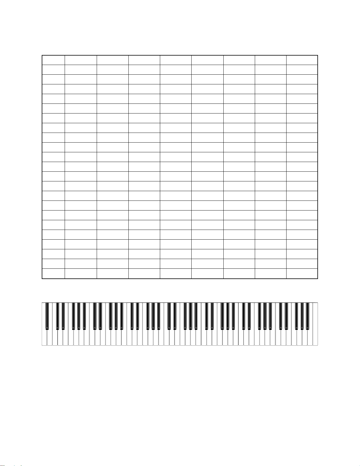
KEY MATRIX
KC0 KC1 KC2 KC3 KC4 KC5 KC6 KC7
FI0 A01 A0#1 B01 C11 C1#1 D11 D1#1 E11
SI0 A02 A0#2 B02 C12 C1#2 D12 D1#2 E12
FI1 F11 F1#1 G11 G1#1 A11 A1#1 B11 C21
SI1 F12 F1#2 G12 G1#2 A12 A1#2 B12 C22
FI2 C2#1 D21 D2#1 E21 F21 F2#1 G21 G2#1
SI2 C2#2 D22 D2#2 E22 F22 F2#2 G22 G2#2
FI3 A21 A2#1 B21 C31 C3#1 D31 D3#1 E31
SI3 A22 A2#2 B22 C32 C3#2 D32 D3#2 E32
FI4 F31 F3#1 G31 G3#1 A31 A3#1 B31 C41
SI4 F32 F3#2 G32 G3#2 A32 A3#2 B32 C42
FI5 C4#1 D41 D4#1 E41 F41 F4#1 G41 G4#1
SI5 C4#2 D42 D4#2 E42 F42 F4#2 G42 G4#2
FI6 A41 A4#1 B41 C51 C5#1 D51 D5#1 E51
SI6 A42 A4#2 B42 C52 C5#2 D52 D5#2 E52
FI7 F51 F5#1 G51 G5#1 A51 A5#1 B51 C61
SI7 F52 F5#2 G52 G5#2 A52 A5#2 B52 C62
FI8 C6#1 D61 D6#1 E61 F61 F6#1 G61 G6#1
SI8 C6#2 D62 D6#2 E62 F62 F6#2 G62 G6#2
FI9 A61 A6#1 B61 C71 C7#1 D71 D7#1 E71
SI9 A62 A6#2 B62 C72 C7#2 D72 D7#2 E72
FI10 F71 F7#1 G71 G7#1 A71 A7#1 B71 C81
SI10 F72 F7#2 G72 G7#2 A72 A7#2 B72 C82
NOMENCLATURE OF KEYS
A#1A#0 G#1F#1D#1C#1 A#6G#6F#6D#6C#6
C1 D1 E1 F1 G1 A1 B1A0 B0
C2 D2 E2 F2 G2 A2 B2 C3 D3 E3 B6A6G6F6E6D6 C7
D#3
C#3A#2G#2F#2D#2C#2
F#3G#3 A#3 C#4D#4 F#4G#4A#4 C#5D#5 F#5G#5 A#5
F3 G3 A3 B3 C4 D4 E4 F4 G4 A4 B4 C5 D5 E5 F5 G5 A5 B5
— 3 —
C#7
C6
A#7G#7F#7D#7
B7A7G7F7E7D7 C8
Page 6
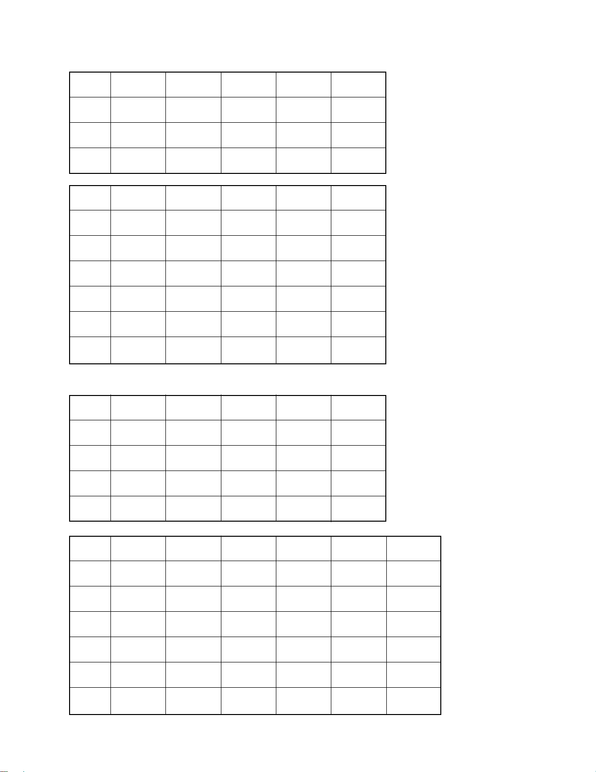
LED MATRIX
LL0
LL1
LL2
1LL0
1LL1
1LL2
2LL0
2LL1
2LL2
LH9
GRAND
PIANO 1
GRAND
PIANO 2
GRAND
PIANO 3
1LH23
REC
PLAY
–––
–––
–––
–––
LH10
ELEC
PIANO 1
ELEC
PIANO 2
ELEC
PIANO 3
1LH24
R/2
L/1
–––
–––
–––
–––
LH11
60'S
E.PIANO
HARPSI-
CHORD
VIBRA-
PHONE
1LH25
MUSIC
LIBRARY
PLAY/STOP
PLAY/STOP
–––
–––
–––
LH12
PIPE
ORGAN
PERC
ORGAN
STRINGS
2LH7
–––
–––
–––
CHORUS
REVERB
SPLIT
LH13
ACOUSTIC
BASS
RIDE ACO
BASS
VARIOUS/
GM TONES
2LH8
–––
–––
–––
BRILLIANCE
CARD
–––
BUTTON MATRIX
SI3
SC3
SC4
SC5
SC6
1SC0
1SC1
1SC2
2SC4
2SC5
2SC6
TEMPO
BEAT
METRONOME
VOLUME
SONG-ACCOMP
VOLUME
1SI0
YES
왖
–––
SYNCHRO/
FILL-IN
–––
–––
–––
SI4
MODE
TOUCH
RESPONSE
TRANSPOSE
TUNE
1SI1
–––
NO
왔
INTRO/
ENDING
–––
–––
–––
SI5
LAYER
BALANCE
EFFECT
MIDI
OTHERS
1SI2
START/
STOP
RECORDER
TEMPO/
SETTING
–––
–––
–––
SI6
ACOUSTIC
BASS
RIDE ACO
BASS
–––
–––
1SI3
PART/
TRACK
RHYTHM
METRONOME
–––
–––
–––
SI7
TONE
SELECT
–––
–––
–––
2SI6
–––
–––
–––
–––
SPLIT
POINT
REVERB
TYPE
2SI7
–––
–––
–––
CHORUS
TYPE
BRILLIANCE
LEVEL
CARD
— 4 —
Page 7
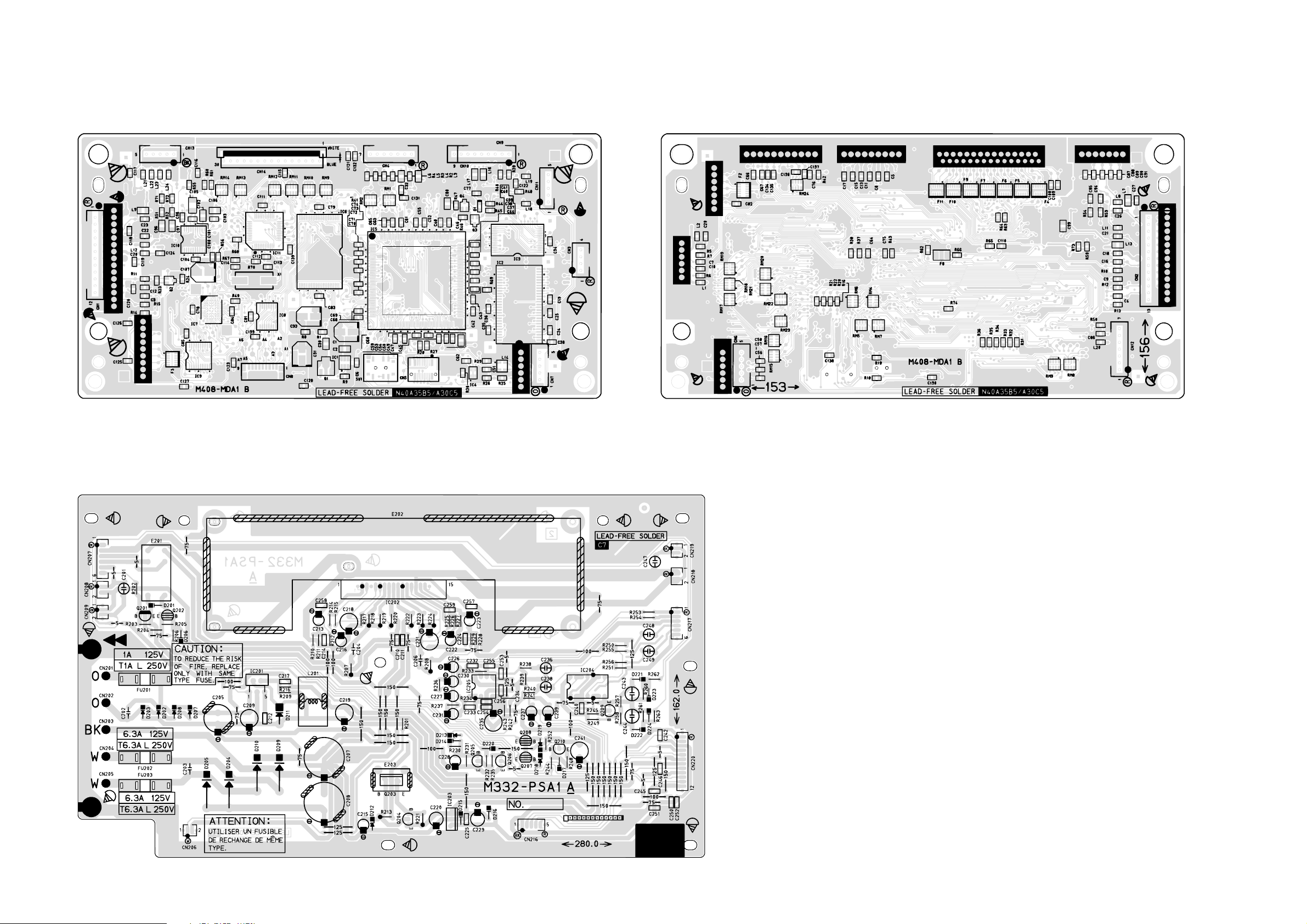
Main PCB M408-MDA1
PRINTED CIRCUIT BOARDS
Console PCB M332-PSA1
Top View
Bottom View
— 5 —
Page 8
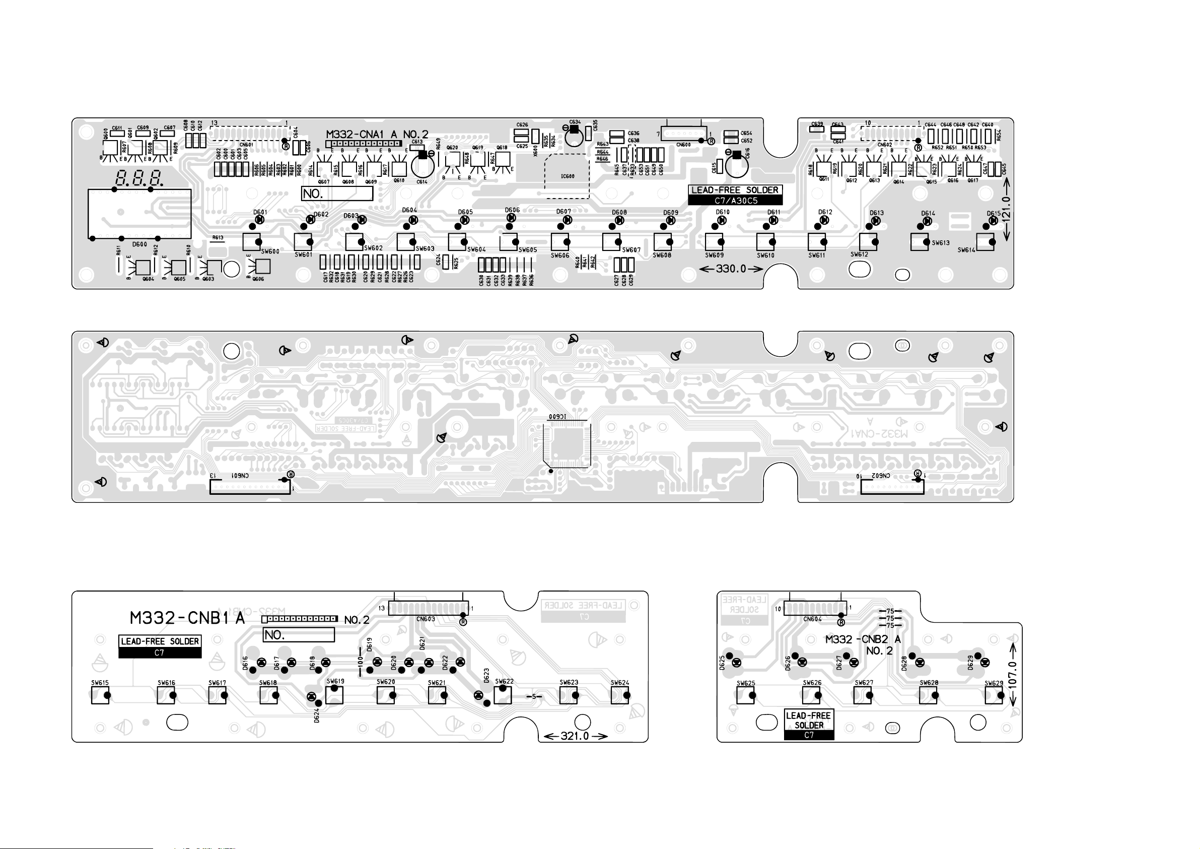
Sub PCB M332-CNA1
Top View
Console PCB M332-CNB1
Bottom View
Console PCB M332-CNB2
— 6 —
Page 9
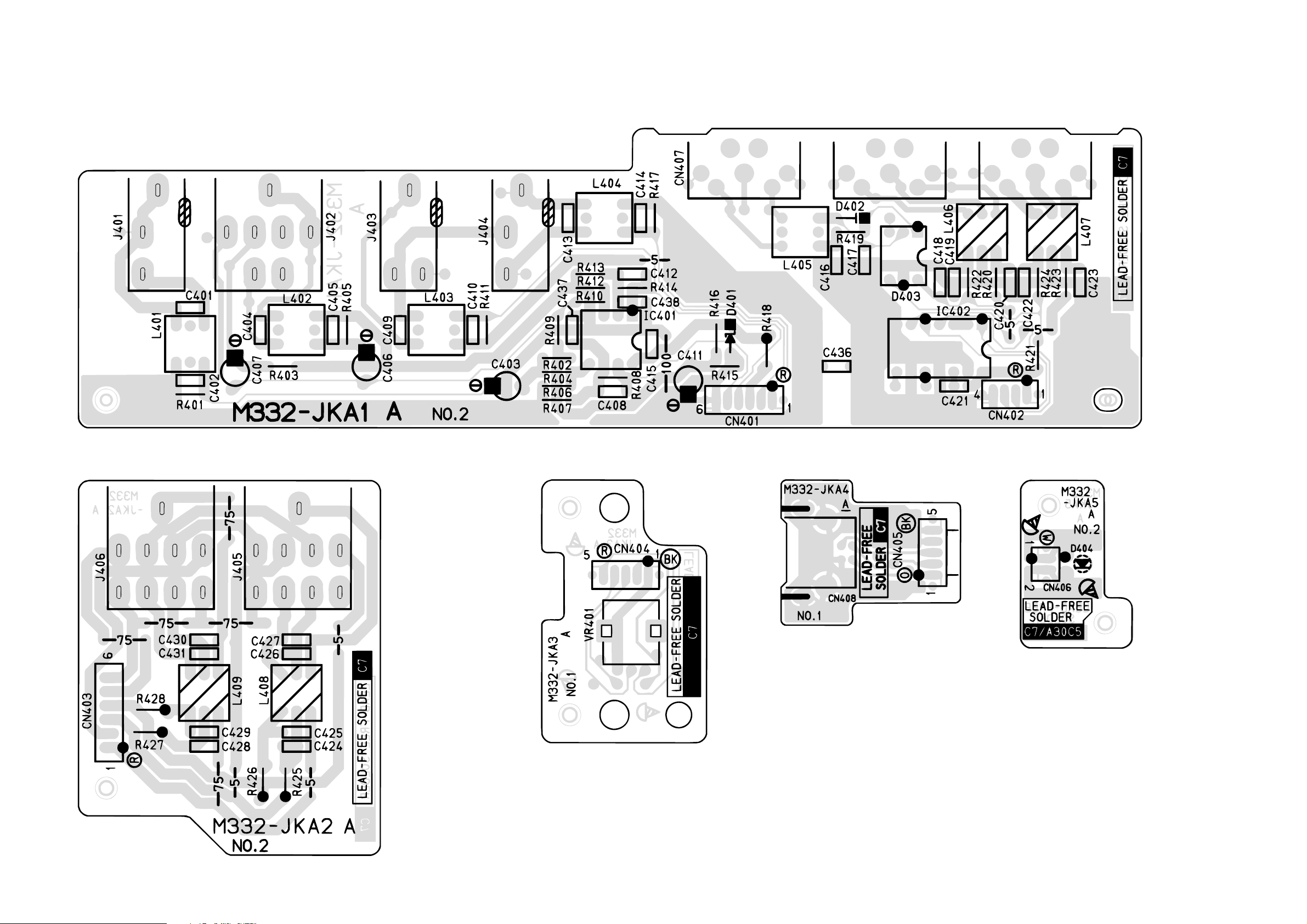
Jack PCB M332-JKA1
Jack PCB M332-JKA2
Jack PCB M332-JKA3
Jack PCB M332-JKA4 Jack PCB M332-JKA5
— 7 —
Page 10
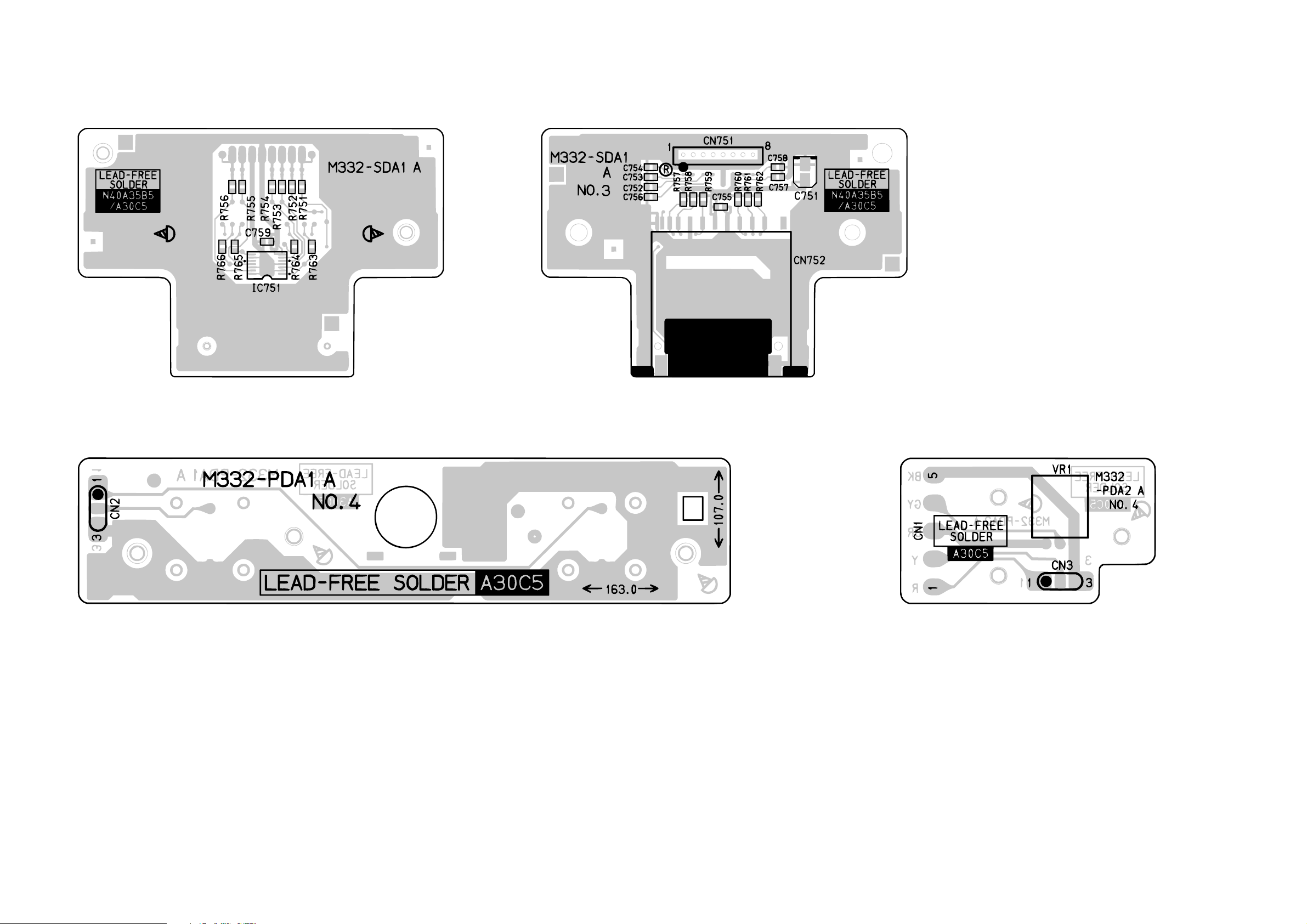
SD CARD PCB M332-SDA1
Top View
Power supply PCB M332-PDA1
Bottom View
Power supply PCB M332-PDA2
— 8 —
Page 11
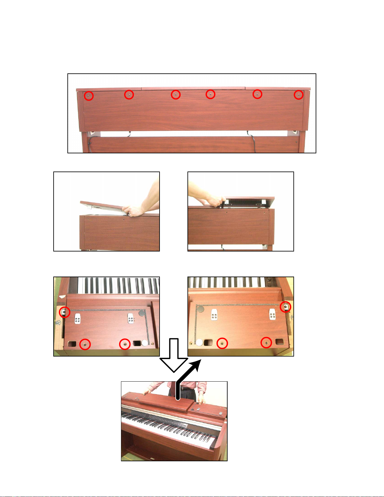
1. Remove 6 screws.
2. Remove 2 T-BRD-S assy.
DISASSEMBLY
3. Remove 6 screws.
4. Remove the T-BRD-M assy.
— 9 —
Page 12
5. Remove the Key cover.
— 10 —
Page 13
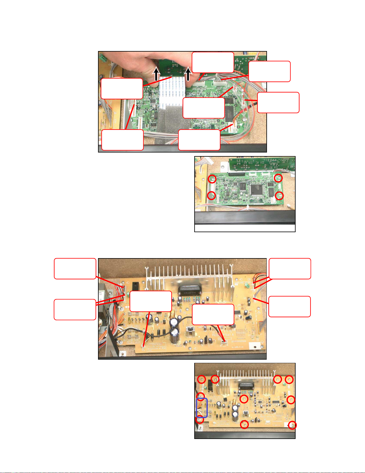
6. Removing the M332-MDA1 PCB
6-1.Remove the 6 connectors, release the lock and then remove the FPC.
Connector
(M332-CNA1)
FPC
(Keyboard)
Connector
(M332-JKA4)
Connector
(M332-SDA1)
Connector
(M332-JKA1)
Connector
(M332-PSA1)
6-1. Remove 4 screws and the M332-MDA1 PCB.
7. Removing the M332-PSA1 PCB
7-1. Remove the 8 connectors.
Connector
(M332-JKA2)
Connector
Connector
(Speaker)
(M332-JKA5)
Connector
(M332-PDA2)
Connector
(M332-JKA3)
Connector
(Speaker)
Connector
(M332-JKA1)
7-2. Remove 5 wires.
7-3. Remove 10 screws and the M332-PSA1 PCB.
— 11 —
Page 14

8. Remove 10 screws and the Power unit (Transfomer, M420-ACA1).
M420-ACA1
9. Removing the M332-JKA1 PCB, M332-JKA4 PCB and Pedal connecor
9-1. Remove 2 screws and the USB unit.
9-2. Remove 2 screws and the M332-JKA4 PCB.
Pedal connecor
Transfomer
M332-JKA1 PCB
9-3. Remove 3 screws and the M332-JKA1 PCB.
9-4. Remove 2 screws and the Pedal connecor.
10. Remove 8 screws and 2 Speakers (big).
11. Remove 4 screws and 2 Speakers unit (small).
12. Remove 4 screws and 2 Speakers (small).
USB unit
— 12 —
Page 15

13. Removing the M332-CNA1, M332-CNB1, M332-CNB2 and M332-SDA1
13-1. Remove 6 screws and the Console unit.
13-2. Remove 2 screws and the M332-SDA1.
13-3. Remove 8 screws and 4 CN bracket.
13-4. Remove 34 screws and the M332-CNA1, M332-CNB1 and M332-CNB2.
— 13 —
Page 16

14. Remove 2 screws and the S-BOLCK (R).
15. Remove 2 screws and the M332-JKA3 and M332-JKA2.
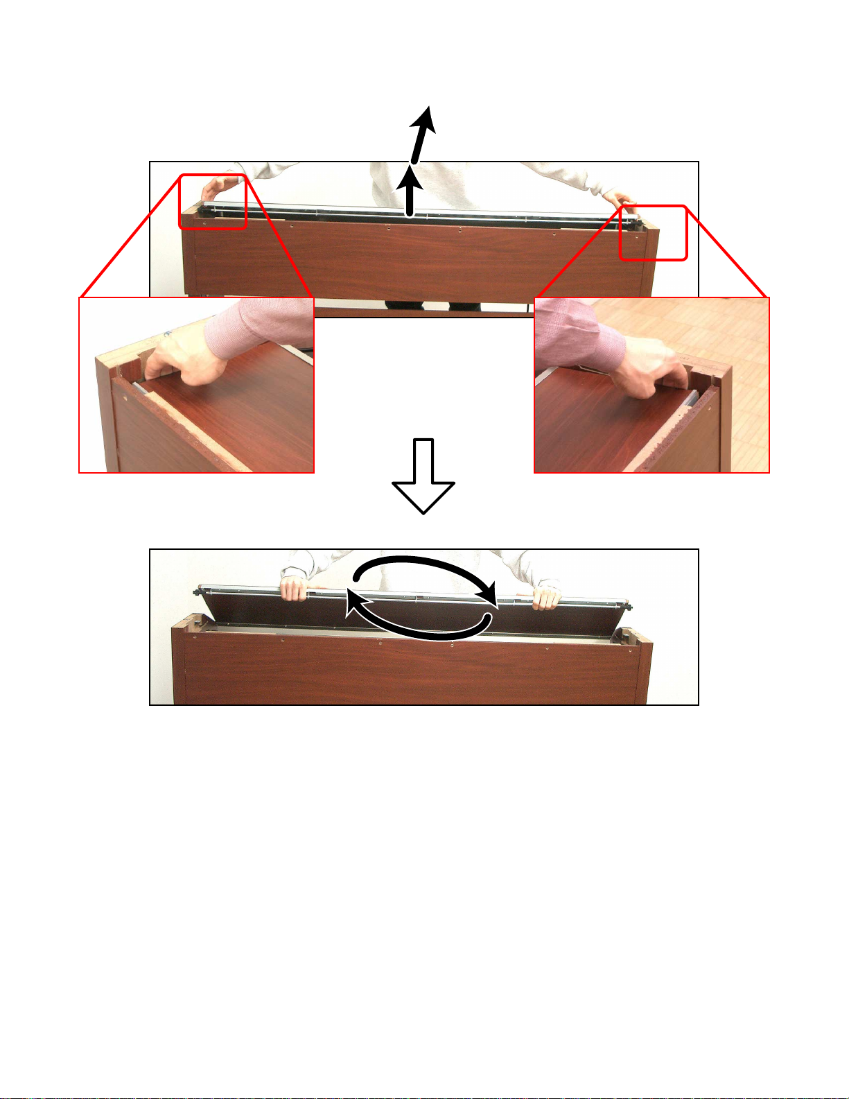
16. Removing the KEYBOARD
16-1. Remove 10 screws.
16-2. Remove 21 screws.
— 14 —
Page 17

16-3. Remove 3 screws and the Keyboard.
16-4. Remove the keys.
Caution while assembling the keys.
• Set the key as shown in figures below.
— 15 —
Page 18

16-5. Remove 8 rubber keys.
* One of the keys has the different length from others.
Caution while assembling the rubber keys.
• Push the rubber keys with the tool like the tweezers, so the projections of the rubber keys matches with
the holes of the lower case.
16-6. Remove 9 screws then the PCB (MCPZ-KYA1).
16-7. Remove 11 screws then the PCB (MCPZ-KYB2).
16-8. Remove 9 screws then the PCB (MCPZ-KYA3).
MCPZ-KYA1
*SCREW x 9
MCPZ-KYB2
*SCREW x 9
17. Remove 2 screws and the M332-JKA5.
MCPZ-KYA3
*SCREW x 9
— 16 —
Page 19

DIAGNOSTIC PROGRAM
■ Initial Setup
1. Connect the Pedal unit and AC adaptor.
2. "Main" volume: MAX.
■ How to start diagnostic program
1. Press and hold “TEMPO/SETTING”, “ /NO” and “ /YES” buttons.
2. “POWER” switch “ON”.
3. Release “TEMPO/SETTING”, “ /NO” and “ /YES” buttons.
* The message shown on the right appears on the display.
■ Diagnostic program
1. RAM check
1 Press “TONE1” button.
* The message shown on the right appears on the display.
2. MODEL check/ Internal (IC5) ROM check/ External ROM check
1 Press “TONE3” button to enter “MODEL check”.
* The message shown on the right appears on the display.
2 Press “TONE3” button to enter “Internal (IC5) ROM check”.
* The message shown on the right appears on the display.
* Carry out checks for each of the 3 blocks.
3 Press “
4 Press “ /YES” button.
5 Press “ /YES” button.
6 Press “TONE3” button to enter “External ROM check”.
* The message shown on the right appears on the display.
* Carry out checks for each of the 3 blocks.
7 Press “ /YES” button.
8 Press “ /YES” button.
9 Press “ /YES” button.
0 Press “TONE/SONG” button.
* The message shown on the right appears on the display.
/YES” button.
— 17 —
Page 20

3. NAND Flash check
1 Press “TONE4” button.
* The message shown on the right appears on the display.
* Confirmation sound sounds.
4. Button check
1 Press “TONE5” button to enter “Button check”.
* The message shown on the right appears on the display.
2 Press the buttons in the following order.
* Confirmation sound sounds.
* If there is a fault with the buttons or you press the wrong button, an error tone sounds
and the message shown on the right is displayed.
_00 _01 _02 _03 _04 _05 _06 _07 _08 _09 _0A _0B _0C _0D _0E _0F _10 _11 _12 _13 _14 _15 _16 _17 _18 _19 _1A _1B _1C
5. Pedal check
1 Press “CARD” button.
* The message shown on the right appears on the display.
2 As you gradually press down on the damper pedal, the display changes as shown
below.
• Pedal pressed lightly.
01 to 3F (hexadecimal)
• Pedal pressed down halfway.
A confirmation tone sounds.
• Pedal pressed down further.
41 to 7E (hexadecimal)
• Pedal pressed down fully.
A confirmation tone sounds.
3 Press the “SOSTENUTE” pedal.
* The message shown on the right appears on the display.
4 Press the “SOFT” pedal.
* The message shown on the right appears on the display.
–
–
— 18 —
Page 21

6. LED/ DISPLAY check
1 Press “TONE6” button.
* Check that the LEDs turn on and off as described.
< PLAY, STOP, MUSIC LIBRARY, RHYTHM, L/1, R2, PLAY, REC, TEMPO/SETTING >
2 Press “TONE6” button.
* Check that the LEDs turn on and off as described.
< 7 SEG LED >
3 Press “TONE6” button.
* Check that the LEDs turn on and off as described.
< TONE >
4 Press “TONE6” button.
* Check that the LEDs turn on and off as described.
< SPLIT, REVERB, CHORUS, BRILLIANCE, CARD >
7. MIDI check
1 Connect MIDI IN and MIDI OUT terminals with a MIDI cable.
2 Press “TONE9” button.
* The message shown on the right appears on the display.
* Confirmation sound sounds.
3 Disconnect the MIDI cable.
8. USB check
1 Press “TONE10” button.
2 Connect USB terminal with a USB cable.
* To a PC that USB driver installed
3 Press “TONE10” button.
* The message shown on the right appears on the display.
* Confirmation sound sounds.
4 Disconnect the USB cable.
— 19 —
Page 22

9. CARD check
1 Inset the SD card.
2 Press and hold the "TONE12" button for at least 1 second.
* The display goes blank for several seconds and then the message shown on the right
appears.
* Confirmation sound sounds.
3 Remove the SD card.
Turn off the power to complete the checking.
— 20 —
Page 23

EXPLODED VIEW
24
26
32
28
42
26
41
22
23
27
36
21
33
31
35
30
34
29
37
27
38
43
26
40
63
53
54
55
44
45
61
62
60
48
49
46
56
52
50
57
58
59
7
4
2
1
51
47
10
8
9
20
17
14
25
15
18
19
16
3
7
39
8
9
5
— 21 —
6
5-1
11
12
13
Page 24

64
x4
x6
65
68
69
70
72
71
67
66
x1
x2
x2
x1
x1
x4
— 22 —
Page 25

PARTS LIST
AP-500
Notes: This parts list does not include the cosmetic parts,
which parts are marked with item No. "R-X" in the
exploded view.
Contact our spare parts department if you need
these parts for refurbish.
1. Prices and specifications are subject to change
without prior notice.
2. As for spare parts order and supply, refer to the
"GUIDEBOOK for Spare parts Supply",
published seperately.
3. The numbers in item column correspond to the
same numbers in drawing.
— 23 —
Page 26

1 AP-500_DI_120V
,10,
,18,
,
,
,
2 AP-500_DI_230V
3 AP-500_EU
4 AP-500_UK
5 AP-500_CI
Specification
MAIN PCB
N 1 10263882 PCB ASSY/MAIN TK-RJM507602*001 11111 AHA
D1 10009218 DIODE 1SS400TE61 11111 AAC
F6,7 10122975 NETWORK/R-C EZASSB516BJ 22222 AAC
F2,3,4,5,
9
11
IC10 10256338 IC CS4351-CZZR 11111 ASC
IC1 10241413 IC R1151N001C-TR-F 11111 AEC
IC8 10123002 IC TC74VHC174FT(EL) 11111 ADC
IC9 10258396 IC TC74VHC541FT(EL.K) 11111 AEC
IC4 10197554 IC TC7SZ126FU(TE85L.F 11111 AEC
N IC5 10255468 LSI MB91F036PFF-GE1 11111 CBC
N IC11 10253886 LSI UPD65942GA-Y299EUA 11111 AXC
IC3 10198126 LSI CY62128DV30LL70ZAX 11111 BNC
N IC2 10170065 LSI EDS1216AATA-75-E 11111 BNC
N IC6 10256337 LSI NAND256W3A2BN6E 11111 BSC
N IC7 10262261 LSI MB82D01181E60LPBNE 11111 BCC
L14 10158809 COIL DLP31SN221SL2L 11111 AI X
L1,2,5,8,11,
12
L4,7,
13.16,17
Q1 22592764 TRANSISTOR 2SB1188T100Q 11111 AB X
Q2,Q4 10202670 TRANSISTOR KTA2014-GR-RTK/P 22222 AAC
Q3 10207675 TRANSISTOR KTC4075-GR-RTK/P 11111 AAC
X1 10133372 CRYSTAL OSCILATOR SMD-49-12M 11111 AI C
10122976 NETWORK/R-C EZASTB63ABJ 77777 AAC
10095204 COIL BLM18AG102SN1D 88888 AA X
19
10122963 COIL BLM21AG102SN1D 55555 ACX
12345
Q'TY
PRICE
CODE
R RemarksN Item Code No. Parts Name
PSA PCB
N 2 10263883 PCB ASSY/PSAJ TK-RJM507604*001 1 1 B 120V
N 2 10263884 PCB ASSY/PSAE TK-RJM507626*001 1 1 1 B 230V
FU201 10052231 FUSE 51MS010L 1 1 AC C 120V
FU201 10054029 FUSE 50T010H 1 1 1 AC C 230V
FU202,203 10047400 FUSE 51MS063L 2 2 AC C 120V
FU202,203 10047413 FUSE 50T063H 2 2 2 AC C 230V
IC203 10257492 IC NJM78M12FA 11111 AE X
Q203 10206676 TRANSISTOR KTC2026-Y-U/P 11111 AB X
L201 10208248 COIL R187-860400NP 11111 ACX
N IC204 10235666 I.C. TC4066BP(N.F) 11111 ACC
N IC202 10231454 IC STK402-070-E 11111 BGC
IC201 10201503 IC PQ1CG21H2FZH 11111 AOC
IC205 10206677 IC NJM2068D-D 11111 AHC
D202,203,
207
208
D211 10209003 DIODE 1N5822-F100 11111 AB X
D204,205,
210
209
D201,206,214,
215,216,217,
220-224
D212 10047556 ZENER DIODE MTZJT-7720A 11111 AA X
D218,219 10047557 ZENER DIODE MTZJT-778.2B 22222 AA X
D213 10047558 ZENER DIODE MTZJT-779.1C 11111 AA X
Q202,207,
208
Q201 10209017 TRANSISTOR KTA1267-GR-AT/P 11111 AAC
Q204,205,
206
209,210
10209183 DIODE PS201-F99 44444 AA X
10209182 DIODE 1N5401-F80 44444 AA X
23153132 DIODE 1SS133T-77 11 11 11 11 11 AA X
10025042 TRANSISTOR 2SD1468STPR 33333 AA X
10206673 TRANSISTOR KTC3199-GR-AT/P 55555 AAC
— 24 —
Page 27

1 AP-500_DI_120V
2 AP-500_DI_230V
3 AP-500_EU
4 AP-500_UK
5 AP-500_CI
N Item Code No. Parts Name Specification
MAIN CASE UNIT
3 10164284 PCB ASSY/ACA1U TK-RJM503880*001 1 1 BA C 120V
3 10164286 PCB ASSY/ACA1E TK-RJM503882*001 1 1 1 AZ C 230V
N 4 10263885 PCB ASSY/JKA1 TK-RJM507612*001 11111 B
D403 10201501 I.C PC900V0NSZXF 11111 AGC
IC401 10206677 IC NJM2068D-D 11111 AHC
IC402 10209159 I.C SN74HCT04AN 11111 ACC
J403 10206815 CONNECTOR JY-6314*01-030 11111 AA X
J401,404 10206816 CONNECTOR JY-6314*01-130 22222 AA X
J402 36120665 JACK/PHONE YKB21-5006 11111 AGC
L406,407 10231919 COIL RB53-856396NP 22222 AAC
L401-405 10231920 COIL RB53-856397NP 55555 AA X
D402 23153132 DIODE 1SS133T-77 11111 AA X
D401 10047557 DIODE MTZJT-778.2B 11111 AA X
5 10164278 CORD ASSY/AC TK-RJM503864*002 1 1 AM C 120V
5 10100792 CORD SET INQ.1258(1) 1 AP C Korea
5 10045706 CORD SET EC2NC-M001A 1 1 AM C Korea/EU
5 10045707 CORD SET BC2NC-M001A 1 BD C UK
5-1 10164279 INLET ASSY/AC TK-RJM503865*001 1 1 1 AH C 230V
N 6 10233377 TRANSFORMER TE-437-1M1A 1 1 CO C 120V
N 6 10233375 TRANSFORMER TE-437-2M1A 1 1 1 CO C 230V
7 10227873 SPEAKER C05JH58 22222 AK BSmall
N 8 10228215 SPEAKER C16JA12 22222 BE BBig
N 9 10262428 NET RJM507410-001V01 22222 ALC
N 10 10263891 CASE ASSY/MIDDLE TK-RJM507209*001 11111 C
N 11 10196297 BRACKET RJM505578-001V01 11111 AX X
N 12 10262354 BOARD/FRONT RJM507221-001V01 11111 BOX
N 13 10263889 PCB ASSY/JKA5 TK-RJM507620*001 11111 C
N 14 10262400 BUTTON/POWER M340318-003V01 11111 AAC
N 15 10262403 KNOB/ROTARY RJM502503-018V02 11111 AAC
N 16 10262405 SIDE BLOCK/L RJM507140-001V01 11111 AHC
N 17 10263901 SW ASSY/PW TK-RJM507696*001 11111 B
N 18 10263887 PCB ASSY/JKA3 TK-RJM507616*001 11111 B
N 19 10263886 PCB ASSYJKA2 TK-RJM507614*001 11111 B
N 20 10262406 SIDE BLOCK/R RJM507141-001V01 11111 X
12345
Q'TY
PRICE
CODE
R Remarks
— 25 —
Page 28

1 AP-500_DI_120V
2 AP-500_DI_230V
3 AP-500_EU
4 AP-500_UK
5 AP-500_CI
N Item Code No. Parts Name Specification
CONSOLE UNIT
N 21 10262347 PANEL/CONSOLE RJM507125-001V01 11111 CAC
N 22 10263890 BLOCK ASSY/SPEAKER TK-RJM507216*001 22222 C
N 23 10262352 PLATE/DISPLAY RJM507384-001V01 11111 AAC
24 69276600 KEY FELT M440829-1 11111 ALC
N 25 10256318 BRACKET/CONSOLE RJM507194-001V01 66666 AHX
N 26 10252615 BUTTON/TACT/A RJM507142-001V01 55555 AAC
N 27 10252616 BUTTON/TACT/A RJM507142-002V01 22222 AAC
N 28 10252617 BUTTON/TACT/A RJM507142-003V01 22222 ABC
N 29 10252618 BUTTON/TACT/B RJM507143-001V01 11111 ABC
N 30 10252619 BUTTON/TACT/B RJM507143-002V01 11111 ACC
N 31 10252620 BUTTON/TACT/B RJM507143-003V01 33333 AFC
N 32 10255459 HIMELON/A RJM507428-001V01 11111 AAC
N 33 10255456 HIMELON/B RJM507429-001V01 11111 AAC
N 34 10255457 HIMELON/C RJM507430-001V01 11111 AAC
N 35 10263893 PCB ASSY/CNA1 TK-RJM507606*001 11111 C
D600 10133612 LED LC5643-12-S6 11111 AQX
IC600 10159709 LSI UPD65881GK-1019ETA 11111 ATC
X600 10093909 CERAMIC OSCILLATOR CSBLA1M00J58-B0 11111 ACX
D601-615 10171339 LED LT5J14-43-S24 15 15 15 15 15 AA X
Q618-620 10211754 TRANSISTOR 2SC5720(TPE4.F) 33333 AA X
Q600-617 10234780 TRANSISTOR KRA105M-AT/P 17 17 17 17 17 AA X
SW600-614 10245364 TACT SWITCH THVV501BAA 15 15 15 15 15 AA C
N 36 10263899 PCB ASSY/CNB1 TK-RJM507608*001 11111 C
N D616-624 10174201 LED LT2P71-81-M1-S07 99999 ANX
SW615-624 10245364 SWITCH/TACT THVV501BAA 10 10 10 10 10 AA C
N 37 10263900 PCB ASSY/CNB2 TK-RJM507610*001 11111 C
N D625-629 10174201 LED LT2P71-81-M1-S07 55555 ANX
SW625-629 10245364 SWITCH/TACT THVV501BAA 55555 AAC
N 38 10263892 PCB ASSY/SDA1 TK-RJM507622*001 11111 C
N 39 10263888 PCB ASSY/JKA4 TK-RJM507618*001 11111 C
N 40 10263902 BOARD ASSY/TOP/M TK-RJM507232*001 11111 C
N 41 10263903 BOARD ASSY/TOP/C TK-RJM507217*001 11111 C
N 42 10263894 BOARD ASSY/TOP/S TK-RJM507218*001 22222 C
N 43 10263895 COVER ASSY/KEY TK-RJM507208*001 11111 C
12345
Q'TY
PRICE
CODE
R Remarks
— 26 —
Page 29

1 AP-500_DI_120V
2 AP-500_DI_230V
3 AP-500_EU
4 AP-500_UK
5 AP-500_CI
N Item Code No. Parts Name Specification
KEYBOARD UNIT
44 10213920 KEY UNIT TK-RJM506362*001 11111 ECB
45 10204304 CHASSIS/KEY RJM505515-001V01 11111 BXC
46 10135317 BLACK KEY RJM502797-001V01 36 36 36 36 36 AC C
47 10135426 WHITE KEY/CEGB RJM502862-001V01 77777 ATC
48 10135427 WHITE KEY/DFA RJM502863-001V01 77777 AQC
49 10135428 WHITE KEY/B RJM502794-001V01 11111 AGC
50 10135429 WHITE KEY/SA RJM502795-001V01 11111 AJC
51 10135430 WHITE KEY/SC RJM502796-001V01 11111 AJC
52 10208265 HAMMER ASSY1/W1 TK-RJM506035*001 13 13 13 13 13 AF C
53 10208266 HAMMER ASSY1/W2 TK-RJM506036*001 13 13 13 13 13 AF C
54 10208267 HAMMER ASSY1/W3 TK-RJM506037*001 13 13 13 13 13 AF C
55 10208269 HAMMER ASSY1/W4 TK-RJM506038*001 13 13 13 13 13 AF C
56 10208275 HAMMER ASSY1/B1 TK-RJM506039*001 99999 AEC
57 10208281 HAMMER ASSY1/B2 TK-RJM506040*001 99999 AEC
58 10208286 HAMMER ASSY1/B3 TK-RJM506041*001 99999 AEC
59 10208290 HAMMER ASSY1/B4 TK-RJM506042*001 99999 AEC
60 37195442 CABLE N30315B1B05-UL2896 11111 AOC
61 10133656 RUBBER/CONATCT/AG RJM502920-001V01 77777 AKC
62 10133635 RUBBER/CONATCT/GC RJM502921-001V01 11111 AGC
63 10208264 PCB ASSY/KEY TK-RJM506061*001 11111 CI C
D801-854,
923-976 10079928 DIODE 1SS133TA 108 108 108 108 108 AA C
D855-922 10079928 DIODE 1SS133TA 68 68 68 68 68 AA C
CN803 10211732 CONNECTOR 30FMZ-ST(LF)(SN) 11111 AGC
12345
Q'TY
PRICE
CODE
R Remarks
STAND
N 64 10263896 SCREW SET TK-RJM507582*001 11111 C
N 65 10263897 BOARD ASSY/STAND/LEFT TK-RJM507374*001 11111 C
N 66 10263898 BOARD ASSY/STAND/RIGHT TK-RJM507375*001 11111 C
N 67 10262429 BOARD/STAND/BACK RJM507250-001V01 11111 CKC
N 68 10263904 BOARD ASSY/PEDAL TK-RJM507376*001 11111 C
N 69 10263905 BOARD ASSY TK-RJM507661*001 11111 C
N 70 10263906 PEDAL ASSY TK-RJM507377*001 11111 C
71 10212698 HARNESS SMR-5P-155-MP5 11111 AMB
N 72 10260690 ADJUSTER FL-20-CR3-KE 11111 AF X
ACCESSORIES
N - 10256364 CD ROM USB12CDROMWL1E 11111 AGC
- 10255460 MUSIC BOOK 05PHCOSCOREWL1A 11111 AX X
— 27 —
Page 30
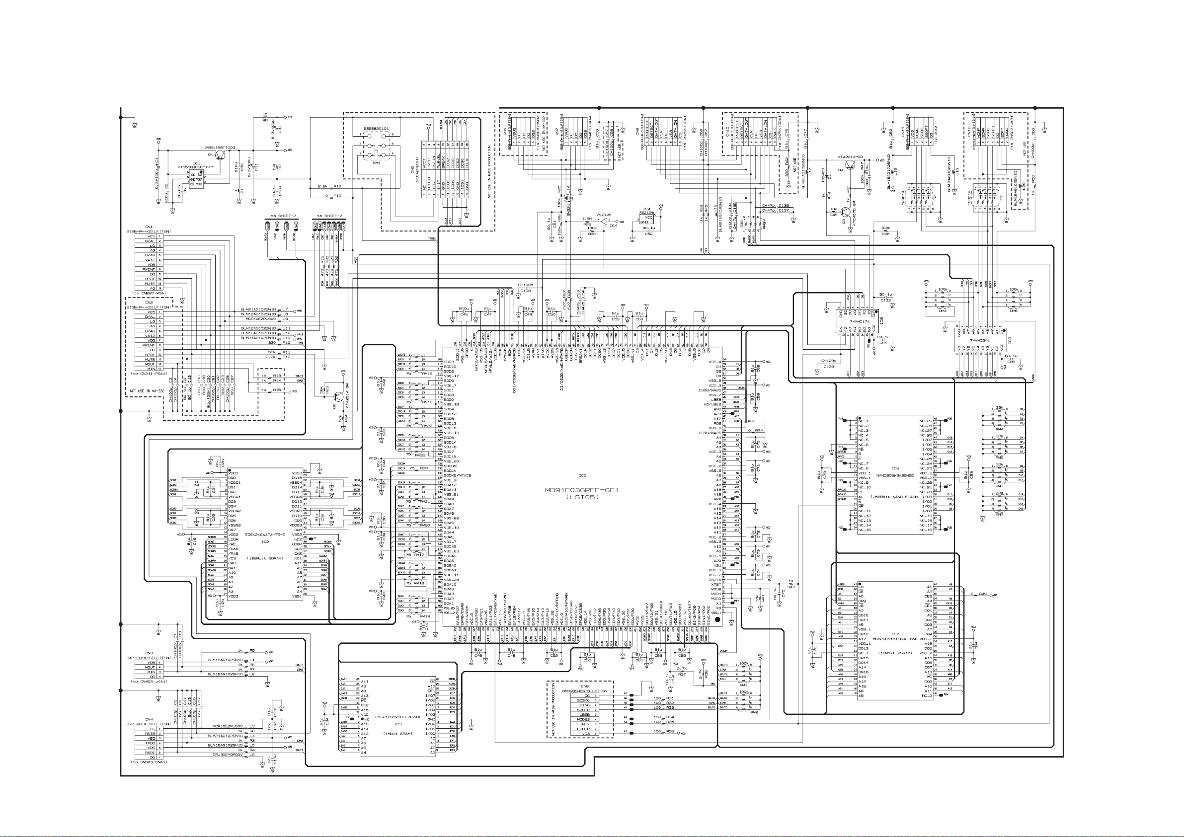
Main PCB M408-MDA1 (1/2)
SCHEMATIC DIAGRAMS
— 28 —
Page 31
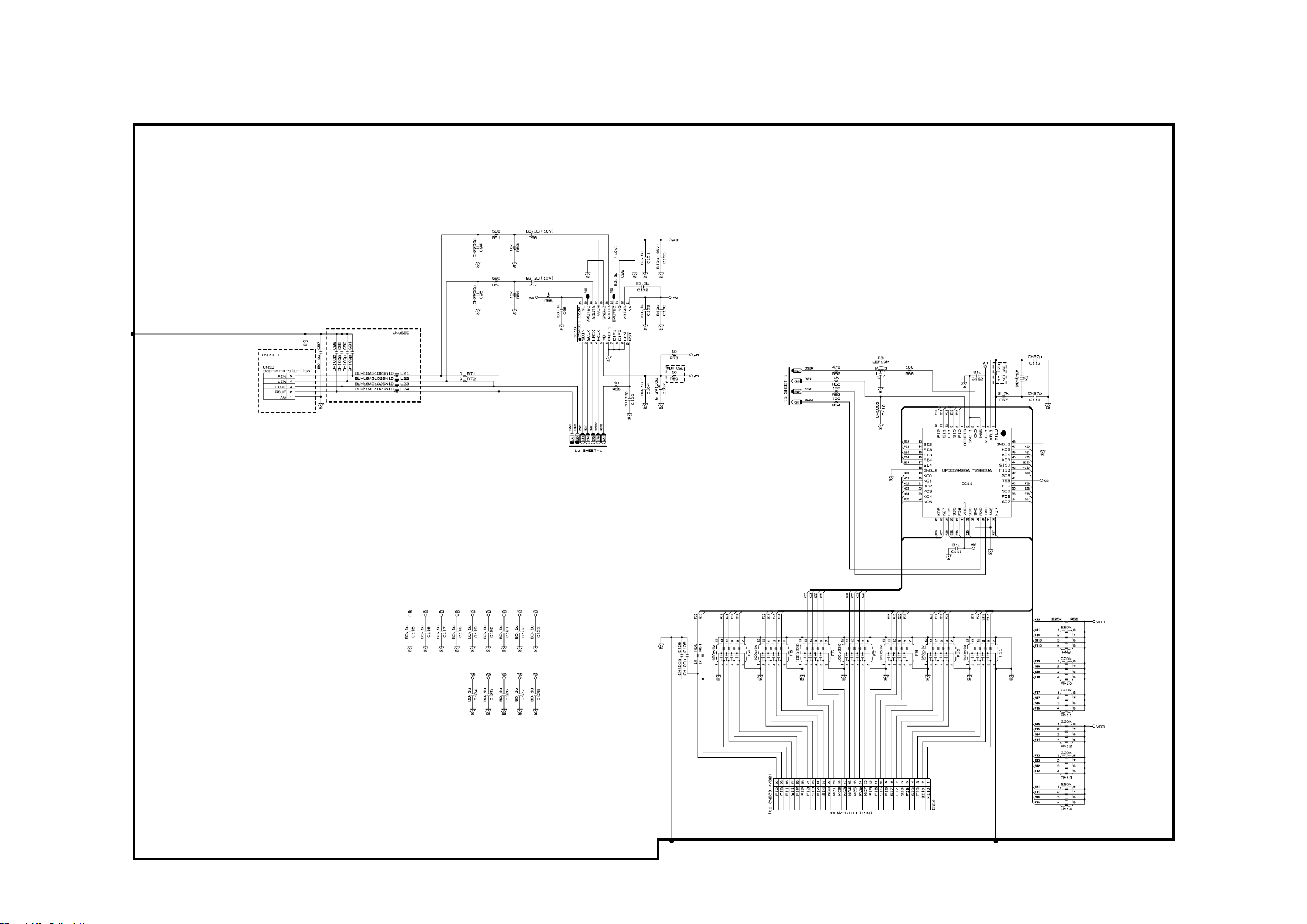
Main PCB M332-MDA1 (2/2)
— 29 —
Page 32

Sub PCB M332-PSA1-E (AC 230V)
— 30 —
Page 33

Sub PCB M332-PSA1-J (AC 100V & AC 120V)
— 31 —
Page 34

Console PCB M332-CNA1
— 32 —
Page 35

Console PCB M332-CNB1
— 33 —
Page 36
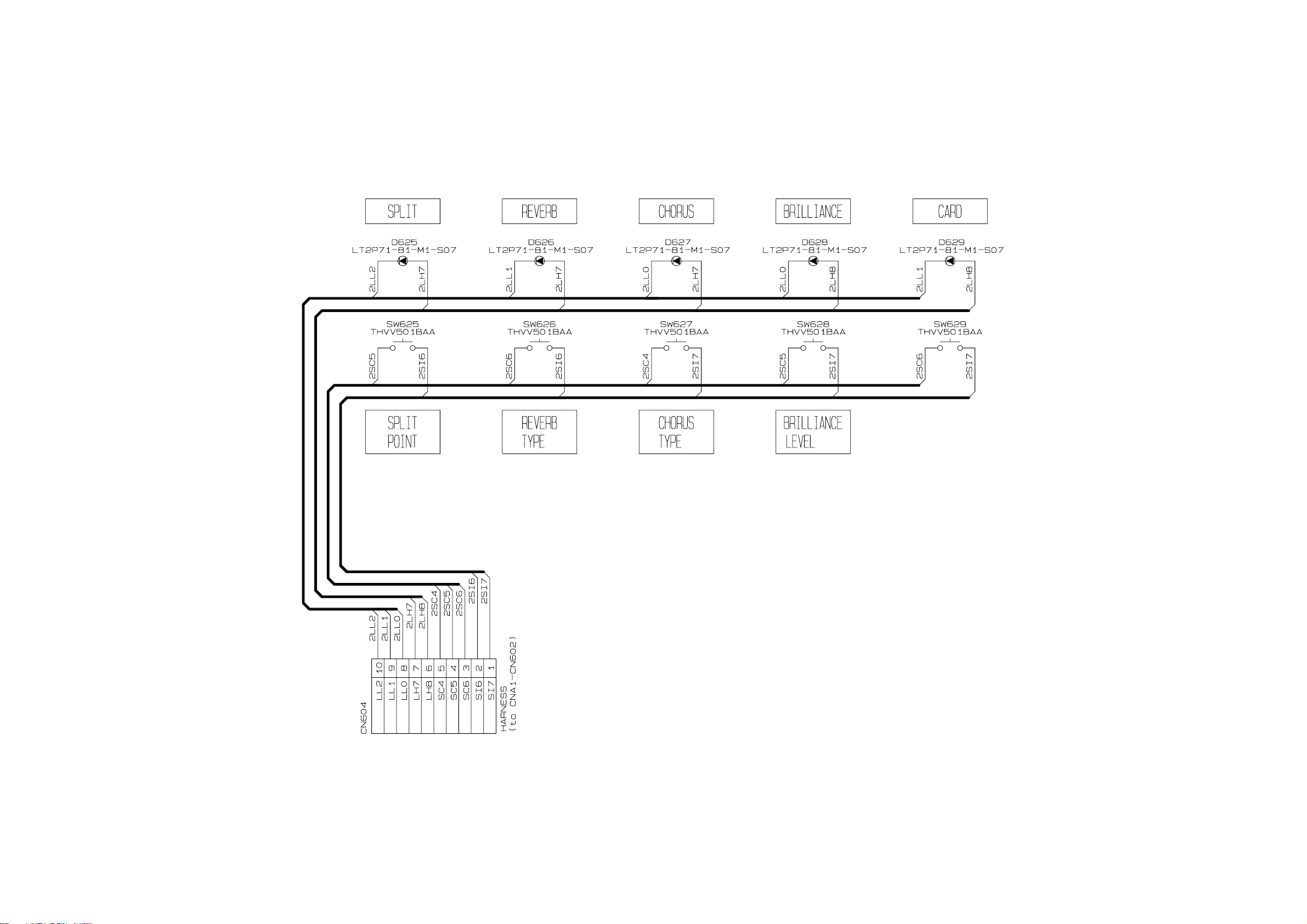
Console PCB M332-CNB2
— 34 —
Page 37
JACK PCB M332-JKA1
— 35 —
Page 38

JACK PCB M332-JKA2 JACK PCB M332-JKA3
— 36 —
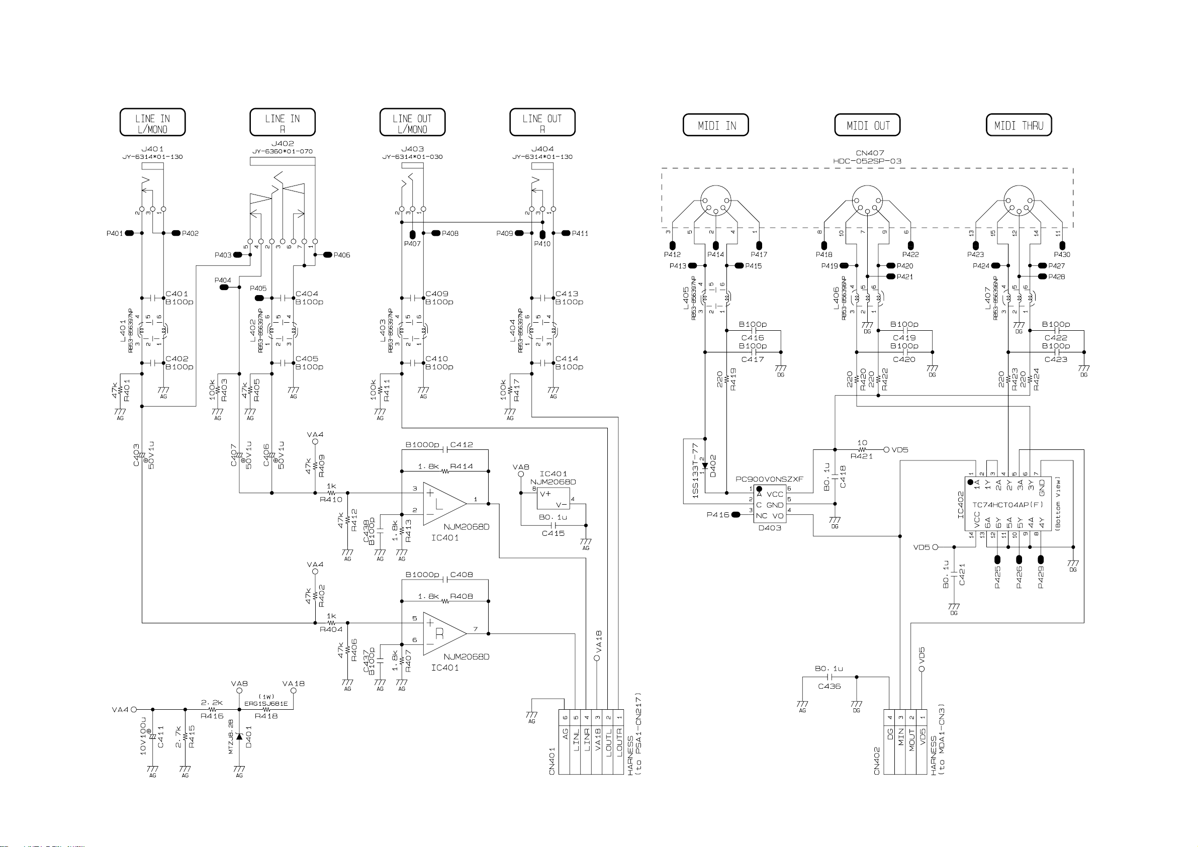
Page 39

JACK PCB M409-JKA4 JACK PCB M409-JKA5
— 37 —
Page 40

SD CARD PCB M332-SDA1
PEDAL PCBs M332-PDA1/PDA2
— 38 —
Page 41

Power supply PCB M420-ACA1 (120V) Power supply PCB M420-ACA1 (230V)
— 39 —
Page 42

CASIO COMPUTER CO.,LTD.
Overseas Service Division
6-2, Hon-machi 1-Chome
Shibuya-ku, Tokyo 151-8543, Japan
 Loading...