

Carrier 48TFD008-014, 48TFE008-014, 48TFF008-012 User Manual
Single-Package Rooftop Heating/Cooling Units
Installation, Start-Up and
Service Instructions
CONTENTS
Page
SAFETY CONSIDERATIONS
INSTALLATION
Step 1 — Provide Unit Support
•ROOF CURB
• SLAB MOUNT
Step 2 — Field Fabricate Ductwork
Step 3 — Install External Trap for
Condensate Drain
Step 4 — Rig and Place Unit
• POSITIONING
Step 5 — Install Flue Hood
Step 6 — Install Gas Piping
Step 7 — Make Electrical Connection
• FIELD POWER SUPPLY
• FIELD CONTROL WIRING
• HEA T ANTICIPATOR SETTINGS
Step 8 — Adjust Factory-Installed Options
• APOLLO CONTROL
• MANUAL OUTDOOR-AIR DAMPER
• OPTIONAL DURABLADE ECONOMIZER
• OPTIONAL ECONOMI$ER
Step 9 — Adjust Evaporator-Fan Speed
START-UP
SERVICE
TROUBLESHOOTING
START-UP CHECKLIST
. . . . . . . . . . . . . . . . . . . . . . . . . . . . . . . .
. . . . . . . . . . . . . . . . . . . . . . . . . . . . . . 2
. . . . . . . . . . . . . . . . . . . . . . . . . . . . . . . . . . . . 34-36
. . . . . . . . . . . . . . . . . . . . . . . . . . . . . . . . . . . . . 36-41
. . . . . . . . . . . . . . . . . . . . . . . . . 42-46
SAFETY CONSIDERATIONS
Installation and servicing of air-conditioning equipment can
be hazardous due to system pressure and electrical components. Only trained and qualified service personnel should
install, repair, or service air-conditioning equipment.
Untrained personnel can perform basic maintenance functions of cleaning coils and filters and replacing filters. All other
operations should be performed by trained service personnel.
When working on air-conditioning equipment, observe precautions in the li terature, ta gs and label s attached t o the uni t, and
other safety precautions that may apply.
Follow all safety codes. Wear safety glasses and work
gloves. Use quenching cloth for unbrazing operations. Have
fire extinguishers available for all brazing operations.
. . . . . . . . . . . . . . . . . . . . . . 1
1-33
. . . . . . . . . . . . . . . . . . .
. . . . . . . . . . . . . . .
. . . . . . . . . . . . . . . . . . . . . 2
. . . . . . . . . . . . . . . . . . . . . . . 8
. . . . . . . . . . . . . . . . . . . . . . 8
. . . . . . . . . . . . 8
. . . . . . 11
. . . . . . . . . 20
. . . . . . . . . . . . . . . . . . . . . . . .CL-1
48TFD008-014
48TFE008-014
48TFF008,012
50 Hz
Disconnect gas piping from unit when leak testing at pressure greater than 3.4 kPa (1/2 psig).
1
2
Before performing service or maintenance operations on
unit, turn off main power swit ch to unit. Electrical shock
could cause personal injury.
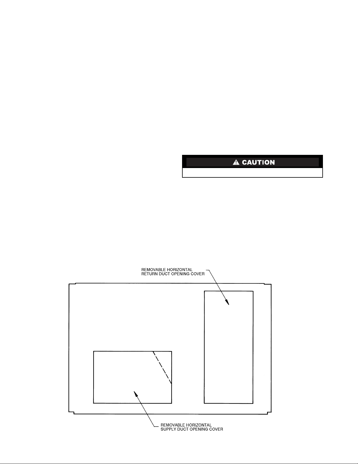
Unit is shipped in the vertical discharge configuration. To
convert to horizontal configuration, remove screws from side
duct opening covers and remove covers. Using the same
screws, install covers on vertical duct openings with the insulation side down. Seals around duct openings must be tight. See
Fig. 1.
Step 1 — Provide Unit Support
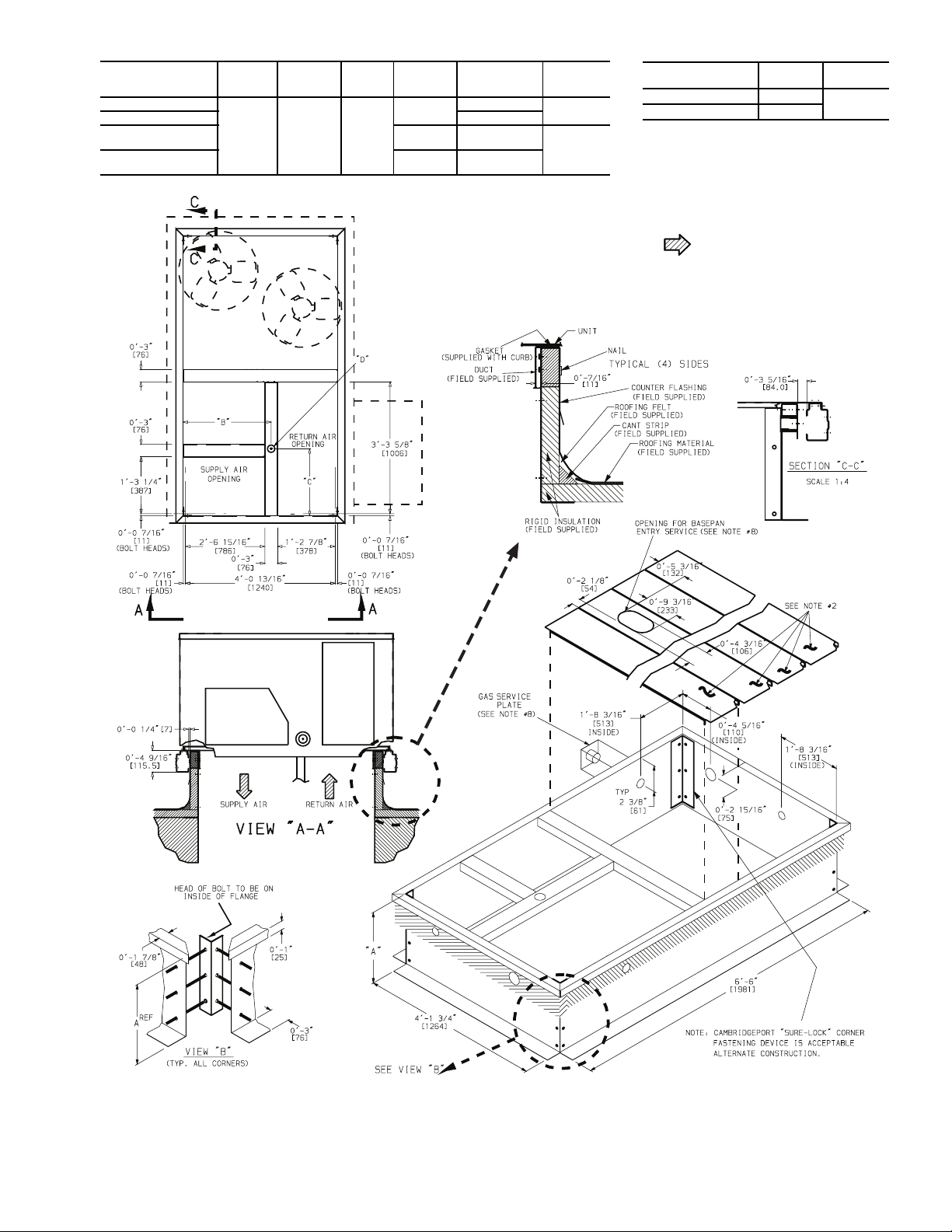
ROO F CU R B — Assemble and instal l acces sory roof curb in
accordance with instructions shipped with curb. See Fig. 2. Install insulation, cant strips, roofing felt, and counter flashing as
shown. Ductwork must be attached to curb. If gas, electric
power or control power is to be routed through the curb, attach
the accessory thru-the-curb service connection plates to the
roof curb in accordance with the accessory installation instructions. Connection plates must be installed before unit is set in
roof curb.
IMPORTANT: The gasketing of th e unit to the roof curb
is critical for a watertight seal. Install gasket supplied
with the roof curb as shown in Fig. 2. Improperly
applied gasket can also result in air leaks and poor unit
performance.
Curb should be level. Unit leveling tolerances a re shown in
Fig. 3. This is necessary for unit drain to function properly. Refer to Accessory Roof Curb Installation Instructions for additional information as required.
Pressures greater than 3.4 kPa (1/2 psig) will
cause gas valve damage resulting in hazardous
condition. If gas valve is ever subjected to pressure greater than 3.4 kPa (
replaced before use. When pressure testing
field-supplied gas piping at pressures of 3.4 kPa
1
(
/2 psig) or less, a unit connected to such piping
must be isolated by manually closing the gas
valve(s).
1
/
psig), it must be
2
INSTALLATION
Manufacturer reserves the right to discontinue, or change at any time, specifications or designs without notice and without incurring obligations.
Book 1 4
Ta b 1 a 6 a
Catalog No. 004-816 Printed in U.S.A. Form 48TF-C1SI Pg 1 1-01 Replaces: New
SLAB MOUNT (Horizontal Units Only) — Provide a level
concrete slab that extends a minimum of 152 mm (6 in.)
beyond unit cabinet. Install a gravel apron in front of condenser coil air inlet to prevent grass and foliage from obstructing airflow.
NOTE: Horizontal units may be installed on a roof curb if
required.
Step 2 — Field Fabricate Ductwork —
ducts to roof curb and building structure on vertical units. Do
not connect ductwork to unit. For horizontal applications, field-
supplied flanges should be attached to horizontal discharge
openings and all ductwork secured to the flanges. Insulate and
weatherproof all external ductwork, joints, and roof openings
with counter flashing and mastic in accordance with applicable
codes.
Ducts passing through an unconditioned space must be in-
sulated and covered with a vapor barrier.
If a plenum return is used on a vertical unit, the return
should be ducted through the roof deck to comply with applicable fire codes.
A minimum clearance is not required around ductwork.
Cabinet return-air static shall not exceed –87 Pa (–.35 in. wg)
with Durablade economizer, –26 Pa (–.30 in. wg) with
EconoMi$er or –112 Pa (–.45 in. wg) without economizer.
These units are designed for a minimum heati ng operation
continuous return-air temperature of 10 C (50 F) (dry bulb), or
an intermittent operation down to 7 C (45 F) (dry bulb), such as
when used with a night set-back thermostat.
Secure all
Step 3 — Install External Trap for Condensate
Drain —
nections are located at the bottom and side of the unit. Unit discharge connections do not determine the use of drain connections; either drain connection can be used with vertical or horizontal applications.
When using the standard side drain connection, make sure
the plug (Red) in the alternate bottom connection is tight before
installing the unit.
The unit’s 19-mm (3/4-in.) condensate drain con-
To use the bottom drai n connection for a roof curb installation, relocate the factory-installed plug (Red) from the bottom
connection to the side connection. See Fig. 4. The piping for
the condensate drain and external trap can be completed after
the unit is in place.
All units must have an external trap for condensate drainage. Install a trap at least 102-mm (4-in.) deep and protect
against freeze-up. If drain line is installed downstream from the
external trap, pitch the line away from the unit at 25 mm (1 in.)
per 3 m (10 ft) of run. Do not use a pipe size smaller than the
19-mm (
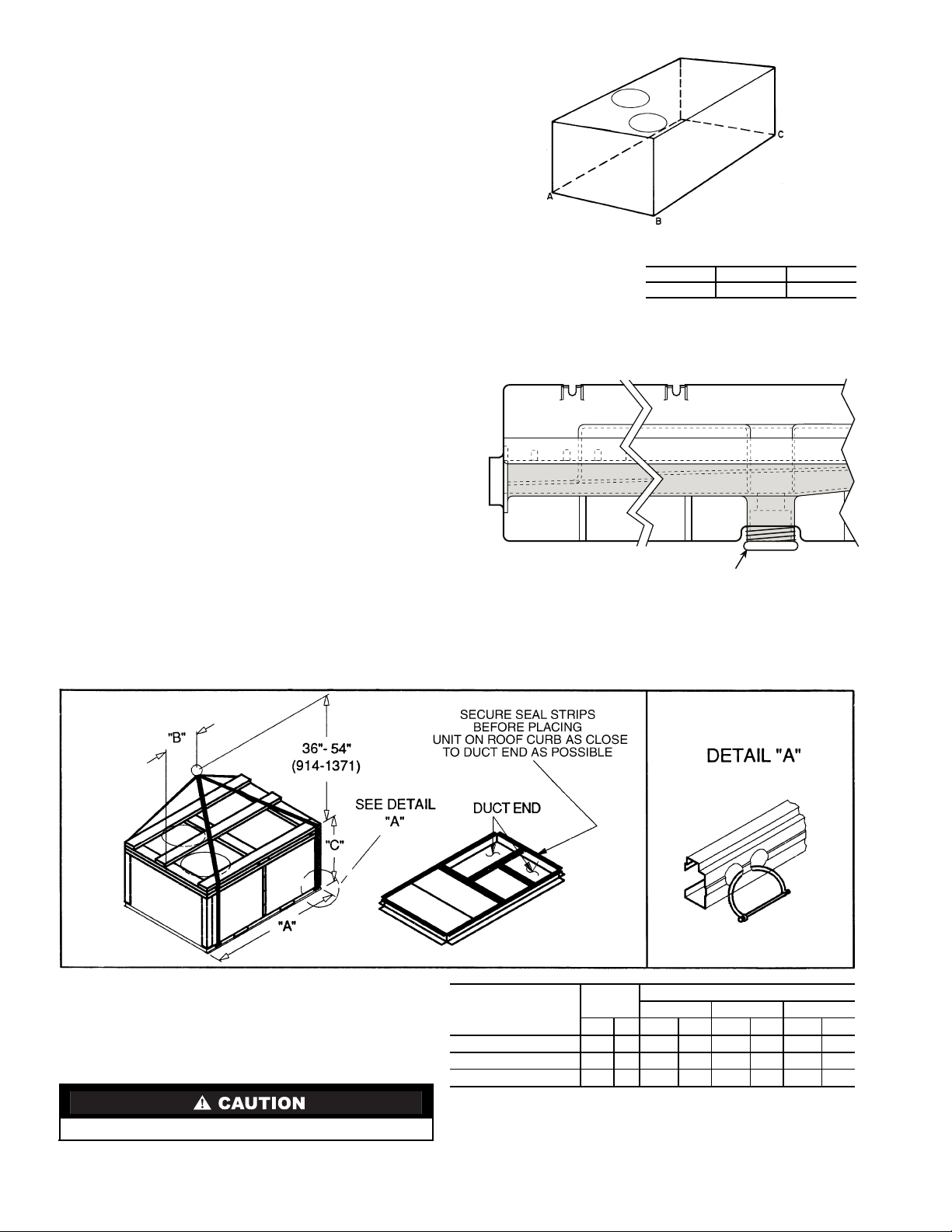
Step 4 — Rig and Place Unit —
transportation damage. File any claim with transportation
agency. Keep unit upright and do not drop. Spreader bars are
not required if top crating is left on unit. Rollers may be used to
move unit across a roof. Level by using unit frame as a reference. See Tables 1A and 1B and Fig. 5 for additional information. Operating weight is shown in Tables 1A and 1B and
Fig. 5.
and 6. Refer to rigging instructions on unit.
POS ITION ING — Maintain cl earan ce around and a bove unit
to provide minimum distance from combustible materials,
proper airflow, and service access. See Fig. 6.
air inlets near exhaust vents or other sources of contami nated
air.
combustion intake or flue outlet.
A, B, or C roof-covering material when roof curb is used.
3
/4-in.) unit connection.
Inspect unit for
Lifting holes are provided in base rails as shown in Fig. 5
All panels must be in place when rigging.
Do not install unit in an indoor location. Do not locate unit
Be sure that unit is installed so that snow will not block the
Unit may be installed directly on wood flooring or on Class
(Copy continued on page 4.)
Fig. 1 — Horizontal Conversion Panels
2
CONNECTOR
PKG. ACCY.
BC
CRBTMPWR001A00
CRBTMPWR002A00 1
CRBTMPWR003A00
2′-8
7
[827]
″
1′-10
/
16
[583]
CRBTMPWR004A00
D ALT
DRAIN
HOLE
15
3
″
1
/
/
16
[44.5]
GAS POWER CONTROL
3
/4″
[19] NPT
1
″
4
″
/
2
[12.7] NPT
3
″
/
4
[19] NPT
3
″ [19] NPT
/
4
1
″ [31.7]
/
4
3
/4″ [19] NPT
11/4″ [31.7]
1
/2″
[12.7]
1
/
2
[12.7]
ROOF CURB
ACCESSORY
“A”
CRRFCURB003A00 1′-2″ [356]
CRRFCURB004A00 2′-0″ [610]
″
NOTES:
1. Roof curb accessory is shipped disassembled.
2. Insulated panels: 1-in. [25] thick polyurethane
3. Dimensions in [ ] are in millimeters.
4. Roof curb: 16-gage steel.
5. Attach ductwork to curb (flanges of duct rest on
6. Service clearance 4 ft [1219] on each side.
foam, 1
curb).
3
/4 lb density.
UNIT SIZE
48TF
008-014
7. Direction of airflow.
8. Connector packages CRBTMPWR001A00 and
2A00 are for thru-the-curb gas type. Packages
CRBTMPWR003A00 and 4A00 are for thruthe-bottom type gas connections.
Fig. 2 — Roof Curb Details
3
Although unit is weatherproof, guard against water from
DRAIN PLUG
MAXIMUM ALLOWABLE
DIFFERENCE mm (in.)
A-B B-C A-C
13 (0.5) 25 (1.0) 25 (1.0)
Fig. 3 — Unit Leveling Tolerances
NOTE: Drain plug is shown in factory-installed position.
Fig. 4 — Condensate Drain Pan
higher level runoff and overhangs.
Position unit on roof curb so that the following clearances
are maintaine d: 7 mm (
base rails on each side and duct end of unit; 84 mm (3
1
/4-in.) clearance between roof curb and
5
/16-in.)
clearance between roof curb and condenser c oil end of unit.
(See Fig. 2, section C-C.)
Locate mechanical draft system flue assembly at least
1219 mm (48 in.) from any opening through which combustion
products could enter the building, and at least 1219 mm (48 in.)
from an adjacent building or combustible material. When unit
is located adjacent to public walkways, flue assembly must be
at least 2.13 m (7 ft) above grade.
Flue vent discharge must have a minimum horizontal clearance of 1219 mm (48 in.) from electric and gas meters, gas regulators, and gas relief equipment.
Flue gas can deteriorate building materials. Orient unit so
that flue gas will not affect building materials.
Adequate combustion-air space must be provided for proper
operation of this equipment. Be sure that installation complies
with all local codes and Section 5.3, Air for Combustion and
Ventilation, NFGC (National Fuel Gas Code), ANSI (American National Standards Institute), latest revision, U.S.A.
Standards.
(Copy continued on page 8.)
NOTES:
1. Dimension in ( ) is in millimeters.
2. Hook rigging shackles through holes in base rail as shown in
detail ‘‘A.’’ Holes in base rails are centered around the unit center of gravity. Use wooden top skid when rigging to prevent rigging straps from damaging unit.
3. Weights include base unit without economizer. See Tables 1A
and 1B for economizer weights.
All panels must be in place when rigging.
UNIT
48TF
D/E/F008
D/E/F012
D/E014
Fig. 5 — Rigging Details
4
MAX
WEIGHT
lb kg in. mm in. mm in. mm
870 395 87.38 2219 40.25 1022 41.31 1050
1035 469 87.38 2219 40.25 1022 49.31 1253
1050 476 87.38 2219 40.25 1022 49.31 1253
DIMENSIONS
‘‘A’’ ‘‘B’’ ‘‘C’’
Table 1A — Physical Data (SI)
UNIT SIZE 48TF 008 012 014
Low Heat (D), Medium Heat (E), High Heat (F) D E F D E F D E
NOMINAL CAPACITY (kW) 21.5 29.2 35.9
OPERATING WEIGHT (kg)
Unit 395 469 476
Durablade Economizer 20 20 20
EconoMi$er 28 28 28
Roof Curb* 65 65 65
COMPRESSOR TYPE Hermetic Hermetic Scroll
Quantity 222
Oil (ml) 1479 ea 1479 ea 1597 ea
REFRIGERANT TYPE R-22
Operating Charge (kg)
Circuit 1 2.10 3.08 3.49
Circuit 2 2.22 3.22 3.49
CONDENSER COIL Enhanced Copper Tubes, Aluminum Lanced Fins
Rows...Fins/m 1...669 2...669 2...669
Total Face Area (sq m) 1.90 1.92 2.30
CONDENSER FAN Propeller Type
Nominal L/s 2880 3050 3050
Quantity...Diameter (mm) 2...559 2...559 2...559
Motor BkW...r/s .19...15.5 .19...15.5 .19...15.5
EVAPORATOR COIL Enhanced Copper Tubes, Aluminum Double-Wavy Fins, Acutrol™ Feed Device
Rows...Fins/m 3...590 3...590 4...590
Total Face Area (sq m) 0.74 0.93 1.03
EVAPORATOR FAN Centrifugal Type
Quantity...Size (mm x mm) 1...381 x 381 1...381 x 381 1...381 x 381
Type Drive Belt Belt Belt
Nominal L/s 1230 1700 1980
Motor kW 1.12 1.50 2.24
Maximum Continuous BkW 1.79 1.79 2.76
Motor Frame Size 56 56 56
Fan r/s Range 8.2-11.7 9.5-13.0 12.0-15.0
Motor Bearing Type Ball Ball Ball
Maximum Allowable r/s 26.7 26.7 26.7
Motor Pulley Pitch Diameter Min/Max (mm) 61/86 71/97 102/127
Nominal Motor Shaft Diameter (mm) 16 16 22
Fan Pulley Pitch Diameter (mm) 178 178 203
Nominal Fan Shaft Diameter (mm) 25 25 25
Belt, Quantity...Type...Length (mm) 1...A...1245 1...A...1245 1...A...1346
Pulley Center Line Distance (mm) 425-489 403-445 403-445
Speed Change per Full Turn of
Movable Pulley Flange (r/s)
Movable Pulley Maximum Full Turns
From Closed Position
Factory Settin g 555
Factory Speed Setting (r/s) 8.2 9.5 12.0
Fan Shaft Diameter at Pulley (mm) 25 25 25
FURNACE SECTION
Rollout Switch Cutout Temp (C) 90.6 90.6 90.6
Burner Orifice Diameter (mm)
Natural Gas — Std 3.05 3.05 3.05 3.28 3.05 3.28
Liquid Propane — Alt 2.44 2.44 2.44 2.59 2.44 2.59
Thermostat Heat Anticipator Setting (amps)
400 v Stage 1 .14 .14 .14 .14 .14
Stage 2 .14 .20 .20 .20 .20
Gas Input (kW) Stage 1 21.1 31.9 39.8 31.9 39.8 43.9 39.8 43.9
Efficiency (Steady State) (%) 80 80 80
Temperature Rise Range (C) –6-10 2-18 7-24 2-18 7-24 4-21 7-24 4-21
Manifold Pressure (kPa)
Natural Gas — Std 8.3 8.3 8.3
Liquid Propane — Alt 8.3 8.3 8.3
Field Gas Connection Size (mm) 13 19 19 19 19 19 19 19
HIGH-PRESSURE SWITCH (kPa)
Standard Compressor
Internal Relief (Differential)
Cutout 2951
Reset (Auto.) 2206
LOW-PRESSURE SWITCH (kPa)
Cutout 48 ± 21
Reset (Auto.) 152 ± 48
FREEZE PROTECTION THERMOSTAT
Opens (C) –1 ± 3
Closes (C) 7 ± 3
OUTDOOR-AIR INLET SCREENS Cleanable
Quantity...Size (mm)
RETURN-AIR FILTERS Throwaway
Quantity...Size (mm) 4...406 x 508 x 51 4...508 x 508 x 51 4...508 x 508 x 51
Bhp — Brake Horsepower
BkW — Fan Input Watts x Motor Efficiency
LEGEND *Weight of 356 mm (14-in.) roof curb.
Stage 2 31.4 50.4 59.8 50.4 59.8 65.6 59.8 65.6
.70 .70 .60
555
3103 ± 345 3448 ± 345
1...508 x 635 x 25
1...406 x 635 x 25
NOTE: The 48TF units have a loss-of-charge (low pressure) switch located in
the liquid line.
5
Table 1B — Physical Data (English)
UNIT SIZE 48TF 008 012 014
Low Heat (D), Medium Heat (E), High Heat (F) D E F D E F D E
NOMINAL CAPACITY (tons) 6.1 8.3 10.2
OPERATING WEIGHT (lb)
Unit 870 1035 1050
Durablade Economizer 44 44 44
EconoMi$er 62 62 62
Roof Curb* 143 143 143
COMPRESSOR TYPE Hermetic Hermetic Scroll
Quantity 222
Oil (oz) 50 ea 50 ea 54 ea
REFRIGERANT TYPE R-22
Operating Charge (lb-oz)
Circuit 1 4-10 6-13 7-11
Circuit 2 4-11 7- 2 7- 8
CONDENSER COIL Enhanced Copper Tubes, Aluminum Lanced Fins
Rows...Fins/in. 1...17 2...17 2...17
Total Face Area (sq ft) 20.50 20.50 25.00
CONDENSER FAN Propeller Type
Nominal Cfm 6100 6500 6500
Quantity...Diameter (in.) 2...22 2...22 2...22
Motor BkW...Rpm
EVAPORATOR COIL Enhanced Copper Tubes, Aluminum Double-Wavy Fins, Acutrol™ Feed Device
Rows...Fins/in. 3...15 3...15 4...15
Total Face Area (sq ft) 8.0 10.0 11.1
EVAPORATOR FAN Centrifugal Type
Quantity...Size (in.) 1...15 x 15 1...15 x 15 1...15 x 15
Type Drive Belt Belt Belt
Nominal Cfm 2600 3500 4200
Motor Hp 1
Maximum Continuous Bhp 2.40 2.40 3.70
Motor Frame Size 56 56 56
Fan Rpm Range 492-700 571-779 717-900
Motor Bearing Type Ball Ball Ball
Maximum Allowable Rpm 1600 1600 1600
Motor Pulley Pitch Diameter Min/Max (in.) 2.4/3.4 2.8/3.8 4.0/5.0
Nominal Motor Shaft Diameter (in.)
Fan Pulley Pitch Diameter (in.) 7.0 7.0 8.0
Nominal Fan Shaft Diameter (in.) ———
Belt, Quantity...Type...Length (in.) 1...A...49 1...A...49 1...A...53
Pulley Center Line Distance (in.) 16.75-19.25 15.85-17.50 15.85-17.50
Speed Change per Full Turn of
Movable Pulley Flange (rpm)
Movable Pulley Maximum Full Turns
From Closed Position
Factory Settin g 555
Factory Speed Setting (rpm) 492 571 717
Fan Shaft Diameter at Pulley (in.) 111
FURNACE SECTION
Rollout Switch Cutout Temp (F) 195 195 195
Burner Orifice Diameter (in. ...drill size)
Natural Gas — Std .120...31 .120...31 .120...31 .129...30 .120...31 .129...30
Liquid Propane — Alt .096...41 .096...41 .096...41 .102...38 .096...41 .102...38
Thermostat Heat Anticipator Setting (amps)
400 v Stage 1 .14 .14 .14 .14 .14
Stage 2 .14 .20 .20 .20 .20
Gas Input (Btuh) Stage 1 72,000 109,000 136,000 109,000 136,000 150,000 136,000 150,000
‘ 107,000 172,000 204,000 172,000 204,000 224,000 204,000 224,000
Efficiency (Steady State) (%) 80 80 80
Temperature Rise Range (F) 20-50 35-65 45-75 35-65 45-75 40-70 45-75 40-70
Manifold Pressure (in. wg)
Natural Gas — Std 3.5 3.5 3.5
Liquid Propane — Alt 3.5 3.5 3.5
Field Gas Connection Size (in.)
HIGH-PRESSURE SWITCH (psig)
Standard Compressor
Internal Relief (Differential)
Cutout 428
Reset (Auto.) 320
LOW-PRESSURE SWITCH (psig)
Cutout 7 ± 3
Reset (Auto.) 22 ± 7
FREEZE PROTECTION THERMOSTAT
Opens (F) 30 ± 5
Closes (F) 45 ± 5
1
OUTDOOR-AIR INLET SCREENS Cleanable
Quantity...Size (in.)
RETURN-AIR FILTERS Throwaway
Quantity...Size (in.) 4...16 x 20 x 2 4...20 x 20 x 2 4...20 x 20 x 2
LEGEND *Weight of 356 mm (14-in.) roof curb.
Bhp — Brake Horsepower
BkW — Fan Input Watts x Motor Efficiency
1
/4...930
1
5
/
2
/
8
1
/4...930
1
/4...930
23
5
/
8
7
/
8
41 41 36
555
/
2
3
/
4
3
/
4
3
/
4
3
/
4
450 ± 50 500 ± 50
1...20 x 25 x 1
1...16 x 25 x 1
NOTE: The 48TF units have a loss-of-charge (low pressure) switch located in
the liquid line.
6
STANDARD
UNIT
UNIT WEIGHT
48TF
D/E/F008
D/E/F012
D/E014
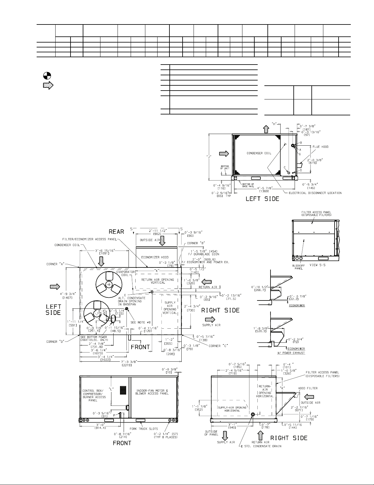
NOTES:
1. Dimensions in [ ] are in millimeters.
Lb Kg Lb Kg Lb Kg Lb Kg Lb Kg Lb Kg Lb Kg ft-in. [mm] ft-in. [mm] ft-in. [mm] ft-in. [mm]
870 395 44 20 62 28 189 86 161 73 239 109 280 127 1-27/8[378] 3-55/16[1050] 2-911/16[856] 2- 27/16[672]
1035 469 44 20 62 28 225 102 192 87 285 129 333 151 2-57/8[759] 4-15/16[1253] 3-03/8[924] 2-107/16[875]
1050 476 44 20 62 28 228 103 195 88 289 131 338 153 1-27/8[378] 4-15/16[1253] 3-03/8[924] 2-107/16[875]
DURABLADE
ECONOMIZER
WEIGHT
ECONOMI$ER
WEIGHT
2. Center of gravity.
3. Direction of airflow.
4. On vertical discharge units, ductwork to be attached to
accessory roof curb only. For horizontal discharge units,
field-supplied flanges should be attached to horizontal discharge openings, and all ductwork should be attached to
the flanges.
5. Minimum clearance (local codes or jurisdiction may prevail):
a. Between unit, flue side and combustible surfaces,
36 in. [914].
b. Bottom of unit to combustible surfaces (when not using
curb), 1 in. [25]. Bottom of base rail to combustible surfaces (when not using curb) 0 inches.
c. Condenser coil, for proper airflow, 36 in. [914] one side,
12 in. [304] the other. The side getting the greater clearance is optional.
d. Overhead, 60 in. [1624] to assure proper condenser fan
operation.
e. Between units, control box side, 42 in. [1067] per NEC
(National Electrical Code).
f. Between unit and ungrounded surfaces, control box
side, 36 in. [914] per NEC.
g. Between unit and block or concrete walls and other
grounded surfaces, control box side, 42 in. [1067] per
NEC.
h. Horizontal supply and return end, 0 inches.
6. With the exception of the clearance for the condenser coil
and combustion side as stated in notes 5a, b and c, a
removable fence or barricade requires no clearance.
7. Units may be installed on combustible floors made from
wood or Class A, B, or C roof covering material if set on
base rail.
8. The vertical center of gravity is 1′-7″ [483] for 008, 1′-11
[584] for 012 and 014 up from the bottom of the base rail.
CORNER
WEIGHT (A)
″
CORNER
WEIGHT (B)
3
″″″″
A
1
/
8
1
″″″″
B
2
/
2
3
″″″″
C
1
/
4
7
″″″″
D
/
Dia [22] Field Control Wiring Hole
8
3
″
″
E
/
[19] - 14 NPT Condensate Drain
″ ″
4
1
″″″″
[13] - 14 NPT Gas Connection 48TFD008
/
2
3
″
″
F
/
[19] - 14 NPT Gas Connection 48TFE,F008
″ ″
4
48TFD,E012 & 014, 48TJF012
″″″″
G
2
Dia [51] Power Supply Knockout
CORNER
WEIGHT (C)
WEIGHT (D)
CONNECTION SIZES
Dia [35] Field Power Supply Hole
Dia [64] Power Supply Knockout
Dia [44] Charging Port Hole
CORNER
“H” “J” “K” “L”
BOTTOM POWER CHART, THESE HOLES
REQUIRED FOR USE WITH ACCESSORY
PACKAGES — CRBTMPWR002A00 (POWER
AND CONTROL) AND CRBTMPWR004A00
(POWER, CONTROL, AND GAS)
THREADED
CONDUIT
SIZE
1
″
″
/
[12.7]
″ ″
2
1
″
″
1
/
[31.7]
″ ″
4
3/
″
″
[19] FPT
″ ″
4
WIRE
USE
24 V
Powe r 1
Gas 1
REQURED
HOLE SIZES
(MAX.)
7
″″″″
[22.2]
/
8
3
″″″″
/
[44.4]
4
5
″″″″
[41.3]
/
8
Fig. 6 — Base Unit Dimensions
7
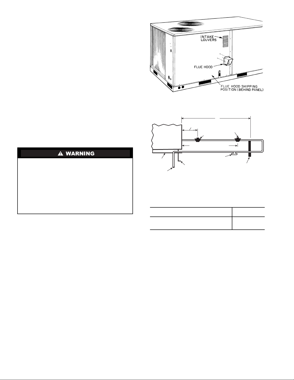
Step 5 — Install Flue Hood —
BASE UNIT
BASE RAIL
FROM GAS METER
ROOF CURB
DRIP LEG PER NFGC*
FIELD-FABRICATED
SUPPORT*
1219 mm (48") MINIMUM
228 mm (9") MINIMUM CLEARANCE
FOR PANELREMOVAL
MANUAL GAS
SHUTOFF VALVE*
GAS
REGULATOR*
X
Fig. 8 — Gas Piping Guide (With Accessory
Thru-the-Curb Service Connections)
SPACING OF SUPPORTS
STEEL PIPE NOMINAL DIAMETER
mm (in.)
X
DIMENSION
m (ft)
13 (
1
/2)
19 or 25 (
3
/
4
or 1)
32 or larger (11/4 or larger)
1.8 (6)
2.4 (8)
3.0 (10)
LEGEND
*Field supplied.
NOTE: Follow all local codes.
NFGC —
National Fuel Gas Code (U.S.A. Standard)
Fig. 7 — Flue Hood Details
Flue hood is shipped
screwed to the burner compartment access panel. Remove
from shipping location and, using screws provided, install flue
hood and screen in location shown in Fig. 7.
Step 6 — Install Gas Piping —
Unit is equipped for
use with type of gas shown on nameplate. Refer to local
building codes.
For natural gas applications, gas pressure at unit gas connection must not be less than 13.5 kPa (4.0 in. wg) (17.0 kPa
[5.0 in. wg] in high heat units) or greater than 44.0 kPa
(13.0 in. wg) while unit is operating. For liquid propane applications, the gas pressure must not be less than 17.0 kPa (5.0 in. wg)
or greater than 44.0 kPa (13.0 in. wg) at the unit connection.
Size gas supply piping for 1.7 kPa (0.5 in. wg) maximum
pressure drop. Do not use supply pipe smaller than unit gas
connection.
NOTE: When installing gas piping to gas valve inlet, use properly sized back-up wrench on inlet flange flats.
Support gas piping as shown in the table in Fig. 8. For example, a 19 mm (
3
/4-in.) gas pipe must have one field-
fabricated support beam every 2.4 m (8 ft).
See Fig. 8 for typical pipe guide and locations of external
manual gas shutoff valve.
Step 7 — Make Electrical Connections
Unit cabinet must have an uninterrupted, unbroken electrical ground to minimize the possibility of personal injury if
an electrical fault should occur. This ground may consist of
electrical wire connected to unit ground lug in control compartment, or conduit approved for electrical ground when
installed in accordance with NEC (National Electrical
Code), ANSI/NFPA (National Fire Protection Association), latest edition (U.S.A. Standards), and local electrical
codes. Do not use gas piping as an electrical ground. Failure to follow this warning could result in the installer being
liable for personal injury of others.
FIELD POWER SUPPLY — All units are factory wired for
the voltage shown on the nameplate.
Refer to unit label diagram for additional informat ion. Pigtails are provided for field service.
When installing units, provide a disconnect per local codes.
Use copper conductors only when splice connectors are used.
All field wiring must comply with local requirements.
Install conduit through side panel openings indicated in
Fig. 6. Route power lines through connector to terminal connections as shown in Fig. 9.
Voltages between phases must be balanced within 2% and
the current within 10%. Use the formula shown in Table 2,
Note 2 to determine the percentage of voltage imbalance. Operation on improper line voltage or excessive phase imbalance
constitutes abuse and may cause damage to electrical components. Such operation would invalidate any applicable Carrier
warranty.
NOTE: If field-installed thru-the-bottom connections are used,
refer to the accessory installation instructions for power wiring.
Refer to Fig. 6 for drilling holes in basepan.
FIELD CONTROL WIRIN G — Install a Carrier-approved
accessory thermostat assembly according to installation instructions included with the accessory. Locate thermostat
assembly on a solid wall in the conditioned space to sense average temperature in accordance with thermostat installation
instructions.
NOTE: For wire runs up to 15 m (50 ft), use no. 18 AWG
(American Wire Gage) insulated wire (35 C minimum). For 15
to 23 m (51 to 75 ft), use no. 16 AWG insulated wire (35 C
minimum). For over 23 m (75 ft), use no. 14 AWG insulated
wire (35 C minimum). All wire larger than no. 18 AWG cannot
be directly connected to the thermostat and will require a junction box and splice at the thermostat. Refer to Table 3 for wire
conversions.
8
Table 2 — Electrical Data
UNIT
48TF
008
012
014
LEGEND
FLA —
HACR —
IFM —
LRA —
MCA —
MOCP —
NEC —
OFM —
RLA —
*Fuse or HACR circuit breaker.
NOTES:
1. In compliance with NEC requirements (U.S.A. Standard) for
multimotor and combination load equipment (refer to NEC Articles 430 and 440), the overcurrent protective device for the unit
shall be fuse or HACR breaker.
2.
Unbalanced 3-Phase Supply Voltage
Never operate a motor where a phase imbalance in supply voltage is greater than 2%.
the percent of voltage imbalance.
% Voltage Imbalance
= 100 x
NOMINAL
VO LTAG E
(50 Hz)
400
(3 phase)
400
(3 phase)
400
(3 phase)
Full Load Amps
Heating, Air Conditioning and Refrigeration
Indoor (Evaporator) Fan Motor
Locked Rotor Amps
Minimum Circuit Amps
Maximum Overcurrent Protection
National Electrical Code (U.S.A.)
Outdoor (Condenser) Fan Motor
Rated Load Amps
max voltage deviation from average voltage
VOLTAGE
RANGE
Min Max RLA LRA FLA FLA MCA MOCP* FLA LRA
360 440 6.4 42.0 0.3 2.6 17.6 20 18 108
360 440 8.9 52.0 0.3 2.6 23.2 30 24 128
360 440 10.4 73.0 0.7 5.4 29.4 35 31 192
Use the following formula to determine
average voltage
COMPR
(ea)
OFM
(ea)
IFM POWER SUPPLY
Example: Supply voltage is 400-3-50.
AB = 393 v
BC = 403 v
AC = 396 v
Average Voltage =
=
= 397
Determine maximum deviation from average voltage.
(AB) 397 – 393 = 4 v
(BC) 403 – 397 = 6 v
(AC) 397 – 396 = 1 v
Maximum deviation is 6 v.
Determine percent of voltage imbalance.
% Voltage Imbalance = 100 x
This amount of phase imbalance is satisfactory as it is below the
maximum allowable 2%.
IMPORTANT: If the supply voltage phase imbalance is
more than 2%, contact your local electric utility company
immediately.
= 1.5%
6
397
MINIMUM UNIT
DISCONNECT
393 + 403 + 396
3
1192
3
Route thermostat cable or equivalent single leads of colored
wire from thermostat subbase terminals to low-voltage connections on unit (shown in Fig. 10) as described in Steps 1-4
below.
1. If unit is mounted on roof curb and accessory thru-thecurb service plate connection is used, route wire through
connection plate.
2. Pass control wires through the hole provided on unit (see
connection D in Connection Sizes table in Fig. 6).
3. Feed wires through the raceway built into the corner post
to the 24-v barrier located on the left side of the control
box. See Fig. 11. The raceway provides the UL-required
(Underwriters’ Laboratories) clearance between highand low-voltage wiring.
4. Connect thermostat wires to screw terminals on lowvoltage connection board.
HEAT ANTICIPATOR SETTINGS — Set heat anticipator
settings at .14 amp for the first stage and .20 amp for secondstage heating, except for 008 low heat. Set both first and second stage heat anticipator settings for 008 at .14 amp.
Table 3 — American/European Wire Conversions
AMERICAN EUROPEAN
Industry
Standard Size
18 AWG
16 AWG
14 AWG
12 AWG
10 AWG
8 AWG
6 AWG
4 AWG
3 AWG
2 AWG
1 AWG
1/0 AWG
2/0 AWG
3/0 AWG
4/0 AWG
250 kcmil
300 kcmil
350 kcmil
400 kcmil
500 kcmil
600 kcmil
AWG —
kcmil —
American
Conversion
Size (mm
13.29 16.0
21.14 25.0
26.65 —
33.61 35.0
42.39 50.0
53.49 —
67.42 70.0
85.00 95.0
107.19 120.0
126.64 150.0
151.97 —
177.90 185.0
202.63 240.0
253.29 300.0
303.95 —
LEGEND
American Wire Gage
Thousand Circular Mils
2
)
0.82 1.0
1.30 1.5
2.08 2.5
3.30 4.0
5.25 6.0
6.36 10.0
Industry
Standard
Size (mm
2
)
9
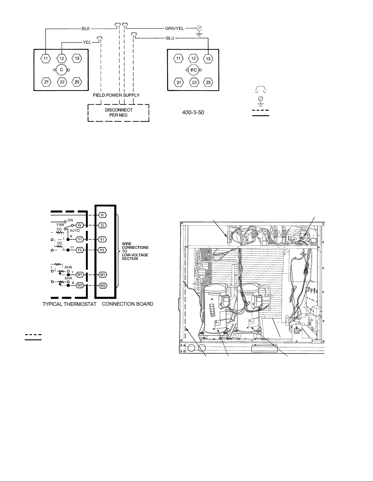
Fig. 9 — Power Wiring Connections
LEGEND
C—
IFC —
NEC —
Contactor
Indoor (Evaporator)
Fan Contactor
National Electrical Code
(U.S.A. Standard)
Splice Connection
(Factory Supplied)
Equipment Ground
Field Wiring
Factory Wiring
LEGEND
AHA —
CC —
Adjustable Heat Anticipator
Cooling Compensator
Field Wiring
Factory Wiring
Fig. 10 — Low-Voltage Connections
UNIT LOW VOLTAGE
CONNECTION
BOARD
RACEWAY
COMPRESSOR
NO. 2
INTEGRATED
GAS UNIT
CONTROLLER
(IGC)
COMPRESSOR
NO.1
Fig. 11 — Field Control Wiring Raceway
and Compressor Location
10
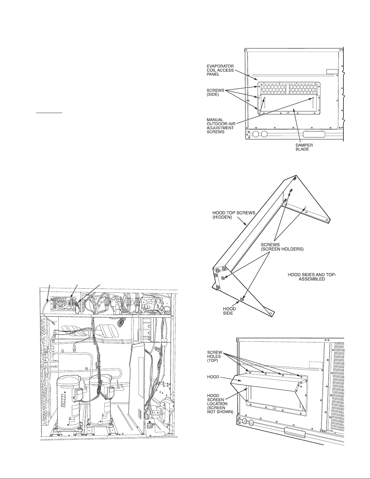
Step 8 — Adjust Factory-Installed Options
Fig. 13 — Damper Panel with Manual
Outdoor-Air Damper Installed
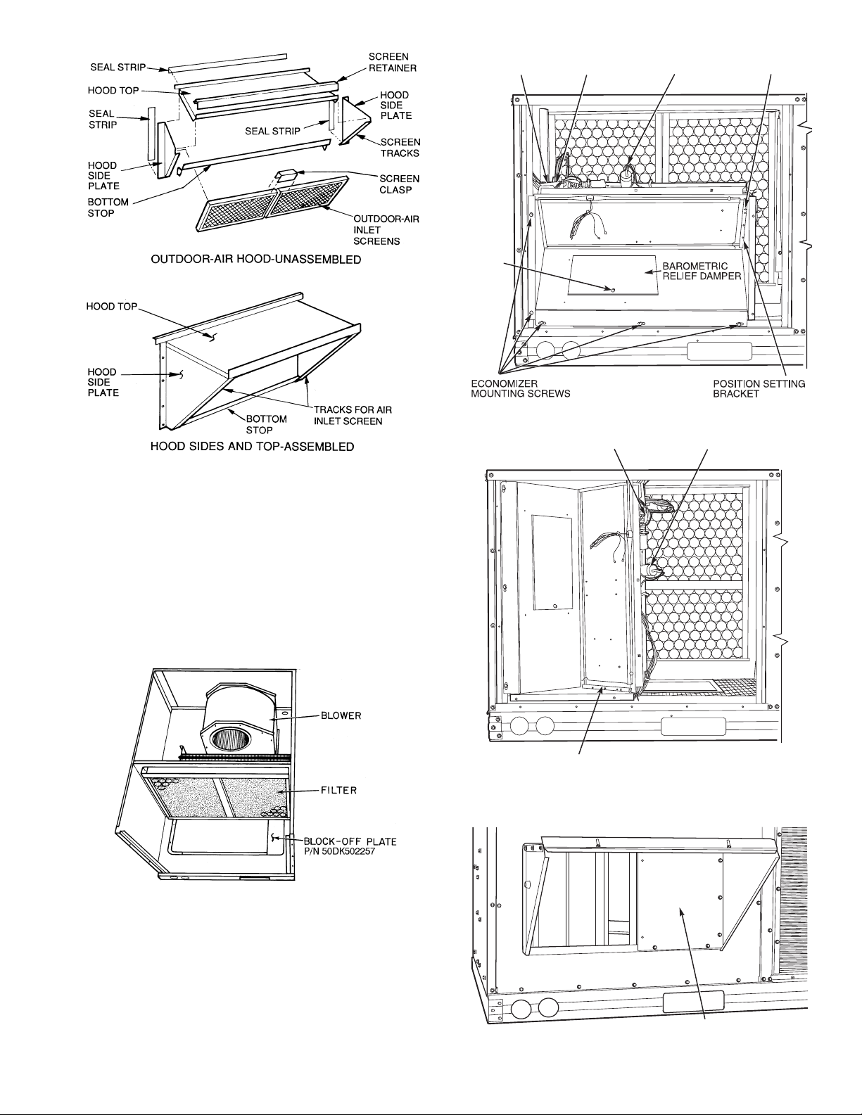
Fig. 14 — Outdoor-Air Hood Details
Fig. 15 — Damper with Hood Attached
APOLLO CONTROL — The optional Apollo control is used
to actively monitor all modes of operation as well as indoor
(evaporator) fan status, filter status, and indoor-air quality. The
Apollo control is designed to work with Carrier TEMP and
®
VVT
systems.
The thermostat must be wired to the Apollo control before
starting the unit. Refer to the Apollo control installation
instructions for information on installing the thermostat. See
Fig. 12 for Apollo location.
MANUAL OUTDOOR-AIR DAMPER — The outdoor-air
hood and screen are attached to the base pan at the bottom of
the unit for shipping.
Assembly:
1. Determine quantity of ventilation required for building.
Record amount for use in Step 8.
2. Remove and save evaporator coil access panel and
screws. See Fig. 13.
3. Separate hood and screen from basepan by removi ng the
screws and brackets securing them. Save al l screws and
discard brackets.
4. Replace evaporator coil access panel using screws from
Step 2.
5. Place hood on front of evaporator coil access panel. See
Fig. 14 for hood details. Secure top of hood with the
screws removed in Step 3. See Fig. 15.
6. Remove and save 6 screws (3 on each side) from sides of
the manual outdoor-air damper. Remove and save 2 manual outdoor-air adjustment screws (one on ea ch side of
damper bl ade) .
7. Align screw holes on hood with screw holes on side of
manual outdoor-air damper. See Fi g. 14 and 15. Secure
hood with 6 side screws from Step 6.
8. Adjust minimum position setting of the dampe r blade by
adjusting the 2 manual outdoor-air adjustment screws on
the front of the damper blade. See Fig. 13. Slide blade
vertically until it is in the appropriate position determined
by Fig. 16. Tighten screws.
9. Remove and save screws currently on sides of hood.
Insert screens. Secure screens to hood using the screws.
See Fig. 15.
WIRING TO
THERMOSTAT
APOLLO
CONTROL
CONTROL
WIRING
Fig. 12 — Apollo Control Factory-Installed
in Typical Unit
11
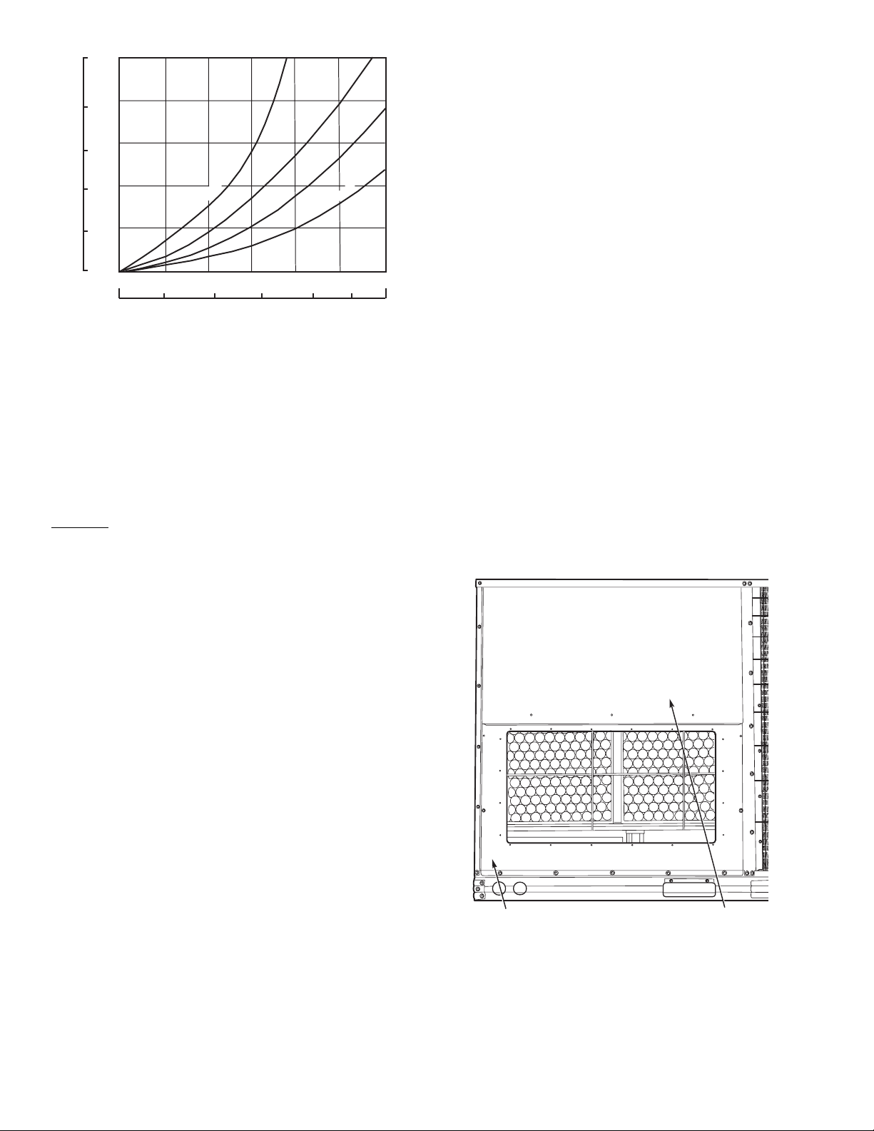
1.0
Fig. 17 — Access Panel Locations
250
0.8
200
0.6
150
2" (51 mm)
0.4
100
NEGATIVE PRESSURE (Pa)
NEGATIVE PRESSURE (in. wg)
0.2
50
0
0
0
1" (25 mm) OPEN
200
68
300
24
OUTDOOR AIRFLOW (cfm x 100)
100
OUTDOOR AIRFLOW (L/s)
3" (76 mm)
4.4" (112 mm)
10 12
400
500
Fig. 16 — Position Setting
OPTIONAL DURABLADE ECONOMIZER — The optional economizer hood assembly is packaged and shipped in the filter section. Dampe r blades an d contro l boards are instal led at the
factory and the ec onomizer is shipped in the vertical di scharge
position.
NOTE: Horizontal discharge block-off plate is shipped with
the air hood package. If unit is to be used for vertical discharge
application, discard this plate.
Assembly
1. Determine if ventilation air is required in building. If so,
determine the minimum amount to be supplied by ea ch
unit and record quantity of ventilation air needed for use
in Step 8.
2. Remove filter access panel by raising panel and swinging
panel outward. Panel is now disengaged from track and
can be removed. No tools are required to remove filter access panel. Remove outdoor-air opening panel. Save panels and screws. See Fig. 17. Remove optional economizer
and outdoor-air damper hood package from filter section.
3. Assemble outdoor-air hood t op and side plates as shown
in Fig. 18. Install seal strips on hood top and sides. Put
aside screen retainer and retainer screw for later assembly . Do not attach hood to unit at this time.
4. On 012 and 014 units, install vertical discha rge block-off
plate on right side over return air duct opening. See
Fig. 19.
5. a. Slide economizer into unit and secure with screws.
See Fig. 20.
NOTE: Be sure to engage rear economizer flange under tabs at
rear of vertical return-air opening.
b. Remove screw and discard from barometric relief
damper. See Fig. 20.
6. To convert to horizontal discharge application:
a. Rotate the economizer 90 degrees until the econo-
mizer motor faces the condenser section (see
Fig. 21).
b. Rotate the barometric relief damper hinge
90 degrees. Barometric relief damper should open
vertically to operate properly.
c. Install horizontal discharge block-off plate over
the opening on the access panel. (Block-off plate
MUST be installed before installing hood assembly.) See Fig. 22.
7. Insert economizer plug into economizer harness. Remove
tape from barometric relief damper. See Fig. 20.
8. If ventilation air is not required, proceed to Step 9. If ventilation air is required, determine the minimum position
setting for required airflow. See Fi g. 23. Adjust minimum
position setting by loosening the screws on the position
setting bracket. See Fig. 24. Slide bracket until the top
screw is in the position determined by Fig. 23. Tighten
screws.
9. Remove tape from outdoor-air thermostat (OAT). Fasten
OAT to inside of hood using screws and spee d clips provided. See Fig. 25. Make sure OAT terminals are positioned up.
10. Replace outdoor-air opening panel using screws from
Step 2. Replace filter acce ss panel. Ensure the filter a ccess panel slides along the tracks and is securely engaged.
11. Fasten hood top and side plate assembly to outdoor-air
opening panel with screws provided.
12. Place knob supplied with economizer on OAT. See
Fig. 25. Set OAT for 1.7° C (3° F) below indoor room
thermostat setting. If accessory enthal py control (EC) is
used in place of OAT, see instructions shipped with EC
for installation and adjustment. See Fig. 25.
13. Connect OAT per Fig. 26.
14. Slide outdoor-air inlet screens into screen track on hood
side plate. While holding screens in place, fasten screen
retainer to hood using screws provided.
NOTE: Refer to Fig. 27 for Durablade economizer barome tric
relief damper characteristics.
OUTDOOR-AIR
OPENING PANEL
FILTER ACCESS
PANEL
12
ECONOMIZER
ECONOMIZER CONTROL BOARD
ECONOMIZER MOTOR
POSITION SETTING BRACKET
BLOCK-OFF PLATE
CONTROL BOARD
SHIPPING
SCREW
ECONOMIZER
PLUG
ECONOMIZER
MOTOR
TOP
SCREW
Fig. 20 — Durablade Economizer Installed in Unit
Fig. 18 — Outdoor-Air Hood Details
Fig. 21 — Horizontal Durablade Economizer
Installation (90 Degree Rotation)
Fig. 19 — Vertical Discharge Block-Off Plate
(48TF012, 014 Units Only)
Fig. 22 — Horizontal Discharge Block-Off Plate
13
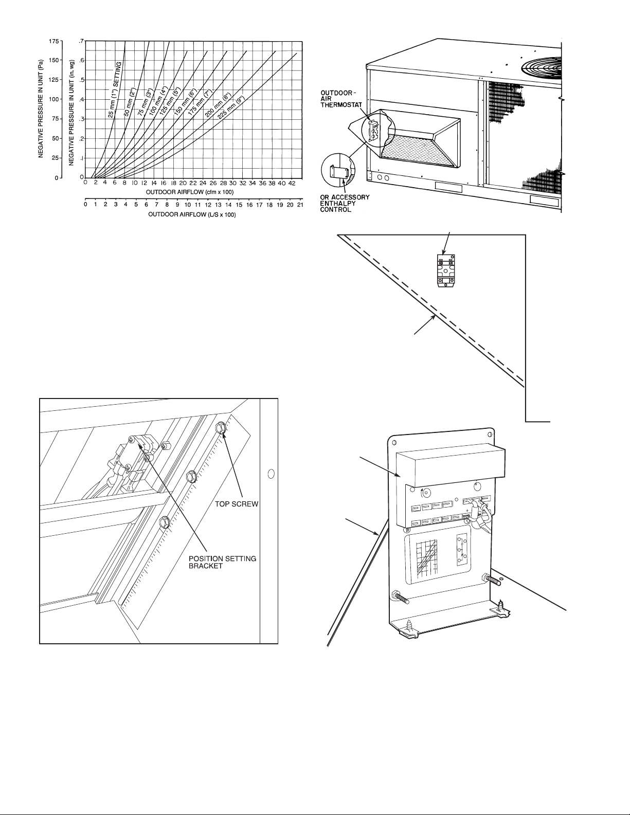
Example:
Given —
Negative Pressure . . . . . . . . . . . . . . . . . . . . . . . . . 25 Pa (0.1 in. wg)
Outdoor Airflow . . .. . . . . . . . . . . . . . . . . . . . . . . . 520 L/s (1100 cfm)
Determine —
Setting = 150 mm (6 in.)
Fig. 23 — Durablade Economizer Damper Minimum
Position Setting
0
TOP
OUTSIDE AIR
SCREEN
OAT
(TERMINALS ARE UP)
UNIT
1
2
3
4
5
6
7
8
9
Fig. 24 — Durablade Economizer Minimum
Position Damper Setting
ENTHALPY
CONTROL
HOOD
RE
B
V
OPEN
P
P1
I
T
Y
30
10
50
OUTDOOR TEMP
55
60
65
70
.
75
°
F
8
0
85
R
POSITION
MINIMUM
1
3
T
5
2
T1
4
CONT
CONT
OR UNPOWERED ST
R
%
1
H
U
U
M
9
I
D
S
8
90
A
H
8
70
ACT RA
CTS SHO
60
1
A
3
8
T
CW
2
A
D
4
V
–SETPOINTS
TINGS: 1.5A
C
DAMPER
A
WN IN HIGH ENTHALPY
C
OPEN
B
2
A
A
3 m
TE
A
RUN, 3.5A IN
M
–CCW
IN
1
. A
DAMPER
CLOSED
T 1
1 VDC
72
7-36
9
.
V
E
.B
C
TR
D
S
S
O
ENTHALPY CONTROL
TR
24
V
A
C
TR1
Fig. 25 — Outdoor-Air Thermostat/
Enthalpy Control Installation
14
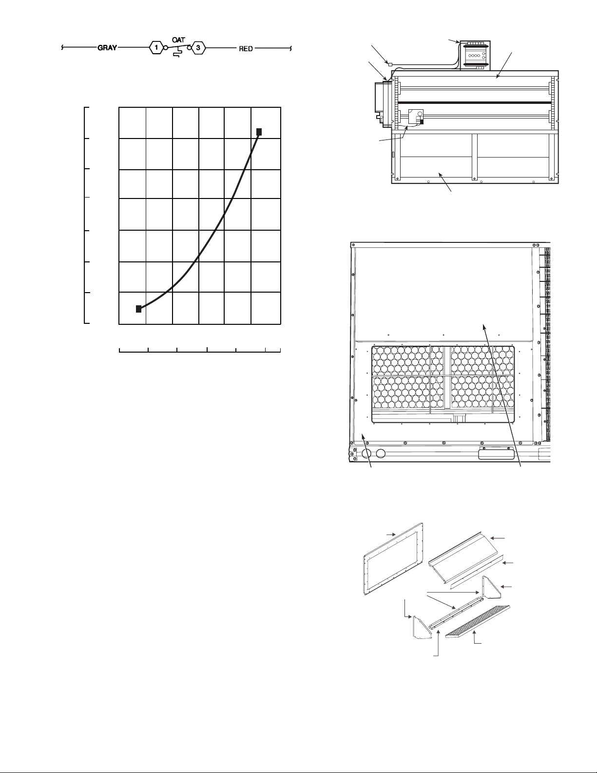
Fig. 26 — Wiring Connections for
CONTROLLER
BAROMETRIC
RELIEF DAMPERS
OUTDOOR AIR
TEMPERATURE
SENSOR
GEAR-DRIVEN
DAMPER
ACTUATOR
ECONOMI$ER
PLUG
Fig. 28 — EconoMi$er Component Locations
OUTDOOR-AIR
OPENING PANEL
FILTER ACCESS
PANEL
Fig. 29 — Typical Access Panel Locations
OUTDOOR AIR
OPENING PANEL
SEAL STRIP
EXHAUST AIR SCREEN
EXHAUST AIR
HOOD TOP
SCREEN
RETAINER
EXHAUST AIR
HOOD SIDES
EXHAUST AIR
BOTTOM BRACKET
Fig. 30 — Exhaust Air Hood Assembly
Outdoor-Air Thermostat
175
150
125
100
75
PRESSURE DROP (Pa)
50
25
0.70
0.60
0.50
0.40
0.30
PRESSURE DROP (in. wg)
0.20
0.10
0
0.00
200 400 600 800 1000 1200
0
100 200 300
CFM
L/s
Fig. 27 — Durablade Economizer Barometric Relief
Damper Characteristics
400 500
570
OPTIONAL ECONOMI$ER — See Fig. 28 for EconoMi$er
component locations.
1. To remove the existing unit filter access panel, raise the
panel and swing the bottom outward. The panel is now
disengaged from the track and can be removed. Remove
the indoor coil access panel and discard. See Fig. 29.
NOTE: If installing an optional Power Exhaust Assembly,
refer to the EconoMi$er Power Exhaust Installation Instructions, then proceed to Step 6. Controller should be mounted in
vertical position as shown in Fig. 28.
2. To assemble the hood assembly remove the EconoMi$er
hood from its packaging. Locate the outdoor air opening
panel. See Fig. 30.
3. Install the 19 mm x 19 mm (
exhaust air hood top panel. Install the 3 mm x 22 mm
(1/8 x 7/8-in.) seal strip on the exhaust air hood side panels
and bottom brackets. Assemble the exhaust air hood to
the outdoor air opening panel as shown in Fig. 30, using
the screws provided. Do not attach hood assembly to unit
at this time.
4. Install the 3 mm x 22 mm (
outdoor air hood top and side panels. Assemble the outdoor air hood to the outdoor air opening panel as shown
in Fig. 31, using the screws provided. Do not attach com-
pleted hood (Fig. 32) assembly to the unit at this time.
3
/4 x 3/4-in.) seal strip on the
1
/8 x 7/8-in. seal strip on the
15
 Loading...