


42 HWS
42 HWS
07 - 09 - 12
42 HWS 18 - 24
INST ALLA TION MANUAL

42 HWS
Split system “Hi-Wall” indoor unit
IR Remote Control “Room Controller” “Group Controller” “Zone Manager”
The unit can be used with infrared Remote Control, with the Carrier “Room Controller” or “Group
Controller” remote control.
Some units can be used also with the Carrier “Zone Manager” remote control.
Infrared control installation instructions are contained in this manual.
Remote controls intallation instructions are contained in the relevant manuals.
The operation and maintenance instructions for the indoor unit and the installation instructions
for the indoor and the outdoor unit are given in the manuals for each unit.
Contents
Page
Dimensions and weight............................................................................... 2
Nominal data............................................................................................... 2
Minimum clearances................................................................................... 3
Material supplied ........................................................................................ 3
Operating limits........................................................................................... 3
General information.................................................................................... 4
Warnings: avoid.......................................................................................... 5
Installation .................................................................................................. 6/7
Refrigerant connections ............................................................................. 8
Electrical connection .................................................................................. 9/10
System configuration.................................................................................. 11
Operating test ............................................................................................. 11
Guide for the owner .................................................................................... 12
Accessories ................................................................................................ 12
IMQ certification.......................................................................................... 12
Cooling only and
heat pump models
Power supply
ENGLISH
42HWS007---703IJ-40
42HWS009---703IJ-40
42HWS012---703IJ-40 230V ~ 50Hz
42HWS018---703IJ-40
42HWS024---703IJ-40
42HWS018---703IJ-40
42HWS024---703IJ-40
230V ~ 60Hz

42 HWS
Dimensions and weight
C
C
A
B
Mod.
07 - 09 - 12
A
B
Mod.
18 - 24
Mod.
A mm
B mm
C mm
kg
kg
07
800
290
145
9.5
ELECTRIC POWER INPUT
Cooling only unit
Cooling Heating
WW
42HWS007---703IJ-40 37 -
42HWS009---703IJ-40 48 -
42HWS012---703IJ-40 48 -
42HWS018----03IJ-40 60
42HWS024----03IJ-40 85
(1)
(1)
Heat pump
09 - 12
800
337
170
10
18 - 24
1150
354
180
15
Table I: Nominal data
• Unit is not suitable for operation in laundry premises.
• Sizing of power supply wires and delay type fuses,
refer to the outdoor unit installation instructions.
-
-
42HWS007---703IJ-40 37 37
42HWS009---703IJ-40 48 48
42HWS012---703IJ-40 48 48
42HWS018----03IJ-40 60
42HWS024----03IJ-40 85
(1)
(1)
60
85
(1)
(1)
Note:
(1)
50 and 60 Hz.

42 HWS
Minimum clearances (mm)
20
ENGLISH
80
20
Table II: Material supplied
Ref. Description Q.ty Use
1 Wall mounting plate 1 Indoor unit installation
2 Screw anchors and screws 4 + 4 Wall plate installation
3 Wireless remote controller with wall bracket and screw 1 Operation and mode selection
4 Batteries 2 Remote control operation
5 Installation manual 1 Unit installation
6 Owner’s manual 1 Use and maintenance
7 Template 1 Indoor unit positioning
Table III: Operating limits
Cooling / Heating Refer to outdoor unit installation manual.
Mains power supply
Nominal single-phase voltage 230V ~ 50Hz 230V ~ 60Hz
Operating voltage limits min. 198V – max. 264V min. 187V – max. 253V

42 HWS
Unit installation
Read this instruction manual thoroughly before starting the
installation.
• This unit complies with low-voltage (EEC/73/23) and electromagnetic compatibility (EEC/89/336) directives.
• The installation must be carried out by a qualified installer.
• Follow all current national safety code requirements.
In particular ensure that a properly sized and connected ground
wire is in place.
• Check that voltage and frequency of the mains power supply are
those required for the unit to be installed; the available power
must be adequate to operate any other possible appliances
connected to the same line.
Also ensure that national safety code requirements have been
followed for the mains supply circuit.
• For sizes 18 and 24 connect the mains supply to the outdoor unit
only.
• Connect indoor and outdoor units with field-supplied copper pipes
by means of flare connections.
Use insulated seamless refrigeration grade pipe only, (Cu DHP
type according to ISO 1337), degreased and deoxidized, suitable
for operating pressures of at least 3000 kPa.
Under no circumstances must sanitary type copper pipe be used.
• Where necessary, use field-supplied 16 mm I.D. PVC pipe of
appropriate length and with the correct thermal insulation for the
condensate drain extension.
• After installation thoroughly test the system operation and explain
all system functions to the owner.
• Leave this manual with the owner for consultation during future
periodic maintenance.
• Use this unit only for factory approved applications: the unit
cannot be used in laundry or steam pressing premises.
WARNING:
Disconnect the mains power supply switch before servicing
the system or handling any internal parts of the unit.
• Do not open the remote controller to avoid possible damage. In
case of malfunctioning contact a qualified service engineer.
• Controller batteries contain polluting elements. When exhausted
they must be disposed of according to local requirements.
• This installation manual describes the installation procedures of
the indoor unit of a residential split system consisting of two units
manufactured by Carrier Villasanta (Italy).
Consult factory or a qualified system engineer prior to connecting
this unit to any other manufacturer's outdoor unit.
Coupling units which have different control systems, may cause
irrevers ble damage and void the warranty protection. The
manufacturer declines any liability for system malfunction resulting
from unapproved coupling.
• The manufacturer declines any liability for damage resulting from
modifications or errors in the electrical or refrigerant connections.
Failure to observe the installation instructions or use of the unit
under conditions other than those indicated in Table III (operating
limits) of outdoor unit installation manual, will immediately void the
unit warranty.
General information
• Failure to observe electric safety codes may cause a fire hazard in
case of short circuits.
• Inspect equipment for damage due to improper transportation or
handling: file an immediate claim with the shipping company. Do
not install or use damaged units.
• In case of any malfunctioning turn the unit off, disconnect the
mains power supply and contact a qualified service engineer.
• This equipment contains ozone depleting substances.
Maintenance of the refrigerant circuit must only be carried out by
qualified personnel.
• All of the manufacturing and packaging materials used for
your new appliance are compatible with the environment and
can be recycled.
• Dispose of the packaging material in accordance with local
requirements.
• This equipment contains coolant that must be disposed of in a
proper manner. When disposing of the unit after its operational
life, remove it carefully. The unit must then be delivered to an
appropriate disposal center or to the original equipment dealer, for
proper environmentally friendly disposal.
Choosing the installation site
Positions to avoid:
• Exposed to direct sun.
• Too close to heat sources.
• On humid walls or positions with water hazard, e.g. laundry premises.
• Where curtains or furniture may obstruct free air circulation.
Recommendations:
• Choose an area free from obstructions which may cause irregular
air distribution and/or return.
• Check that the wall surface is flat enough to allow easy and safe
installation. The wall structure should be strong enough to carry the unit
weight and avoid deformation, rupture or vbration during operation.
• Consider using an area where installation is easy.
• Choose a position that allows for the clearances required (see drawing).
• Look for a position in the room which assures the best possible air
distribution.
• Install unit in a position where condensate can easily be piped to
an appropriate drain.

42 HWS
Warnings: avoid…
Any obstruction of the unit air outlet or return.
Exposure to oil vapours.
ENGLISH
Exposure to direct sunshine, when unit is operating in cooling
mode; always use shutters or shades.
Positions too close to heating sources which may damage the unit.
Connecting condensate piping to sewage system drain without appropriate trap. Trap height must be calculated according to the unit discharge
head in order to allow sufficient and continuous water evacuation.
Installation in areas with high frequency waves.
Any rise in the condensate drain piping.
Horizontal condensate drain piping with less than 2% slope.
Slack on electrical connections. Disconnecting refrigerant
connections after installation: this will cause refrigerant leaks.
Only partial insulation of the piping.
Installation not correctly leveled which will cause condensate dripping.
Flattening or kinking the refrigerant pipes or condensate pipes.
Excessive height difference between outdoor and indoor units (see
installation manual of outdoor unit).
Unnecessary turns and bends in interconnecting tubing. Excessive
interconnecting tube length (see installation manual of outdoor unit).

42 HWS
Installation
20
20
243
140 mm
120 mm
D mm
223
270 mm - Ø 70
380
800
314
270 mm - Ø 70
IMPORTANT NOTE:
This unit has no refrigerant expansion device.
30
108,5
270
243
223
120 mm
70
140 mm
D mm
110
130
20
23
Plate
Mod. A B C D
A
227
07
C
B
09 - 12
Mod. 07 - 09 - 12
290 40 44 60
337 87 60 90
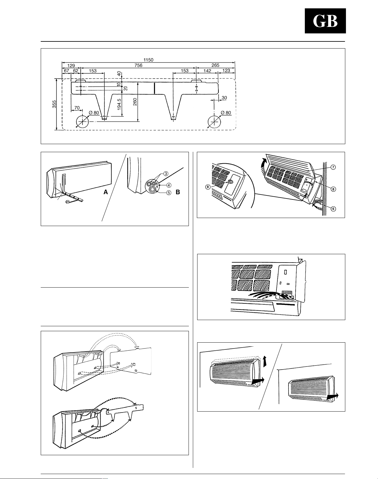
Establish the direction of refrigerant tubing.
Refrigerant tubes can run in directions indicated by 햲, 햳, 햴, 햵, 햶.
For directions 햳, 햴 and 햵, break the knockout in the side panel.
Direction 햶 is recommended for sizes 18 and 24 only.
Mod. 07 - 09 - 12
Mod.18 - 24
Installation of the wall mounting plate.
Refer to "Minimum clearance" between unit, side walls and ceiling.
Place mounting plate against the wall, then level with a plumb line
or spirit level and mark the position of the mounting holes to be
drilled.
Wall mounting plate centre line of size 18 and 24 does not coincide
with the installed unit centre line, which is indicated with a vertical
line on the mounting plate.
Mod. 18 - 24
Making the hole in the external wall for interconnecting tubes to
the outdoor unit.
Drill a 70 or 80 mm dia. hole (depending on unit size) in the
external wall using the plate or the template provided with the unit
(see " Table II, Ref.7).
5-10 mm
햲
Ø 70 / 80 mm
햳
햲 Indoors
햳 Outdoors
The hole should have a 5-10 mm slope toward the outside. Insert
the plastic conduit provided.
Drill holes and install the plate using the 4 screw anchors and
screws provided.
Check that no vibrations can occur by movement of the plate.
Pass the electric connecting wires through the conduit (see
electrical connections).
42 HWS
Installation
햴 Refrigerant tubes of the indoor unit
Separate insulation for each tube
햵 Electrical connecting wires
햶 Condensate drain pipe
Condensate drain pipe and refrigerant tubes.
• Fasten the electric wires and refrigerant tubes together. Allow an
additional length to the electric wires for easy connection to the unit
connectors.
• Run refrigerant tubes so the condensate drain pipe is always
positioned at the bottom of the conduit. Connect the condensate
pipe to a proper drain using a flexible PVC pipe. Horizontal runs
between indoor unit and drain orifice must have a minimum 2% slope.
ENGLISH
Template
Mod: 18 - 24
Keep the bottom end of the unit slightly away from the mounting
plate and hold this position with spacer stick 햷. Open the front
panel 햸 and remove the electrical terminal box cover 햹.
This operation can be carried out without disassembling the
unit front panel.
Note:
Do not kink or flatten the tubes. Avoid bends with a bending radius
of less than 100 mm. Do not bend copper tubes more than three
times at the same point. Do not remove flare fittings from unit tubes
before actually making the connections. Do not fasten the insulation
too tightly to the tubes with straps or tape.
Mod. 07 - 09 - 12
Mod. 18 - 24
Attach the unit to the mounting plate by means of the upper hooks.
Pass the electrical wires through the proper slot provided in the
back panel of the unit and pull them out in the front.
Do not make electrical connections at this stage.
Mod. 18 - 24
Mod. 07 - 09 -12
Remove the spacer stick. To fasten the unit:
• Sizes 07, 09, 12
Slightly pull the bottom end of the unit from the wall, then push it
firmly so that the bottom hooks engage in the appropriate slots.
• Sizes 18, 24
Push the unit firmly so that the bottom hooks engage in the
appropriate
Should it be necessary to detach the unit, proceed in the opposite way.
slots.

42 HWS
Refer to the outdoor unit installation manual for tube sizing,
and limitations (slopes, length, number of curves allowed,
refrigerant charge, etc.)
Tubing diameter
Gas Liquid
Mod. (Suction) (Discharge)
mm (inches) mm (inches)
07 10 (3/8") 6 (1/4")
09 10 (3/8") 6 (1/4")
12 12 (1/2") 6 (1/4")
18 12 (1/2") 6 (1/4")
24 16 (5/8") 6 (1/4")
For refrigerant tubes use seamless, insulated refrigeration grade tube,
(Cu DHP type according to ISO 1337), degreased and deoxidized, suitable
for operating pressures of at least 3000 kPa. Under no circumstances use
sanitary type copper pipe.
Flaring the end of the tubing
Remove protective caps from the copper tube ends. Position tube
end downward, cut the tube to the required length and remove the
burrs with a reamer.
Remove flare nuts from the unit connections and place them on the
tube end. Flare the tube with the flaring tool.
Flare end must not have any burrs or imperfections.
The length of the flared walls must be uniform.
Lubricate the tube end and thread of the flare fitting with anti-freeze
oil. Finger-tighten the fitting several turns, then tighten it fully with
two wrenches by applying the tightening torque indicated in the
table.
Connection to the unit
Insufficient tightening torque will cause gas leaks. Overtightening
the fittings will damage the tube flaring and cause gas leaks.
Tubing diameter Torque
mm (inches) Nm
6 (1/4") 15 - 20
10 (3/8") 31 - 35
12 (1/2") 50 - 55
16 (5/8") 50 - 55
Once all connections have been completed, check for leaks by
applying soapy water to them. Finally wrap connections with anticondensate insulation and tighten with tape, without exerting great
pressure on the insulation. Repair and cover any possible cracks in
the insulation. Connection pipes and electric cables between indoor
and outdoor units must be fixed to the wall with appropriate
conduits. If the system power supply is connected to the indoor unit
(only for models 07 - 09 and 12) the power supply cable must also
be fixed to the wall in the proper conduit.
Check
Pour water into the condensate drain pan and check that it flows
freely to the drain.
Refrigerant connections
햵 Tube
햶 Tube insulation
햷 Fastening tape
햲 Adjustable wrench or torque wrench
햳 Outdoor end
햴 Indoor end
햲
햴
햳
햵
햶
햷
L
L
42 HWS
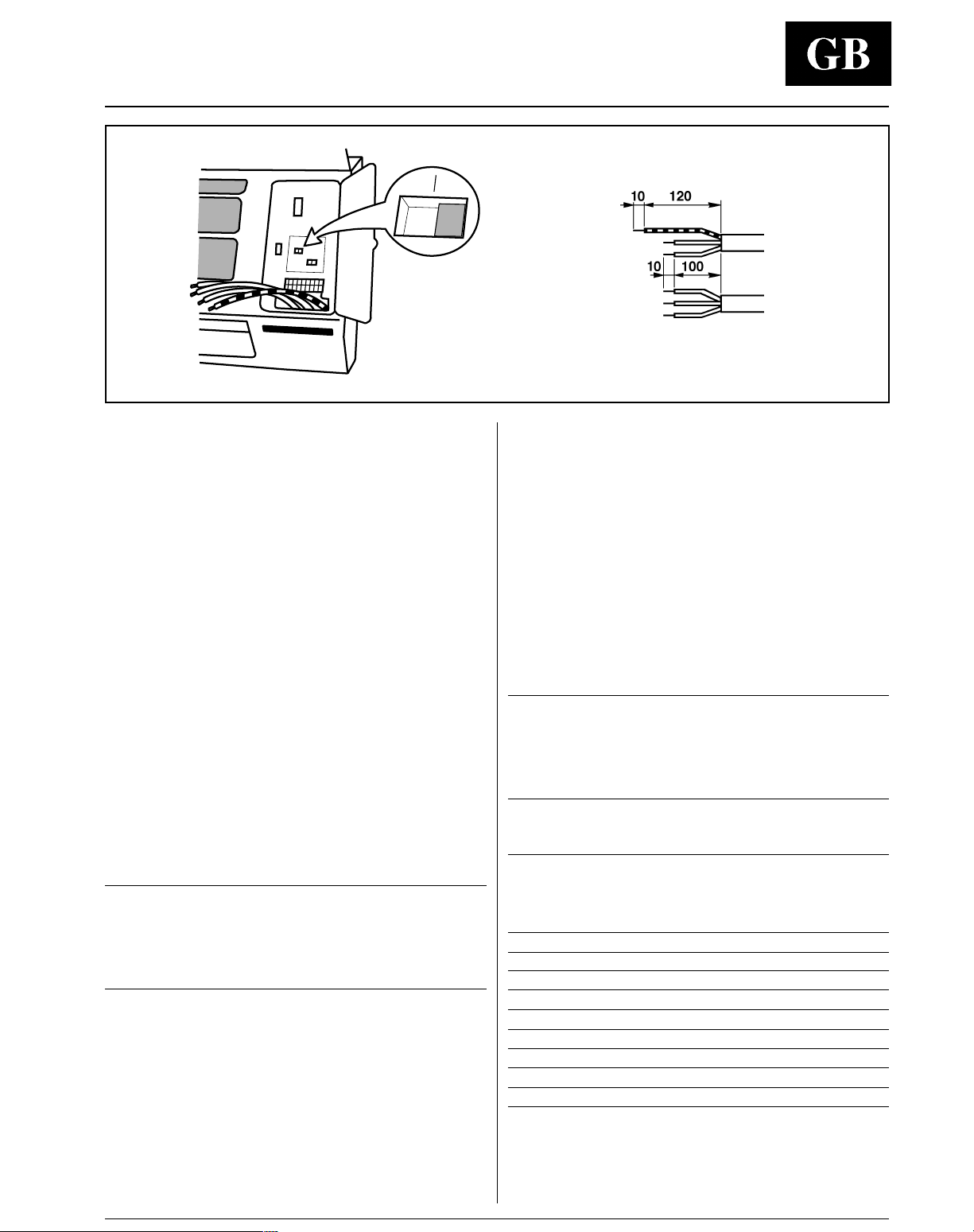
Electrical connections
1
2
Operating mode setting
Prior to making the electrical connections, set the switch
shown in the picture as follows:
• Position 1 for cooling only unit;
• Position 2 for heat pump unit.
In order to reset, in the event of incorrect switch positioning,
proceed as follows:
• Disconnect the power supply.
• Reposition the switch correctly.
• Connect the power supply.
ENGLISH
Heat pump unit
• Make ground connection prior to any other electrical
connections.
• Make electrical connections between units prior to proceeding to
mains supply unit connection.
• Ensure that mains supply connection is made through a switch
that disconnects all poles, with contact gap of a least 3 mm.
• The mains supply connecting cable must be H07 RN-F (or higher)
type, while the indoor - outdoor unit interconnecting wires must be
A05 RN-F type (or higher), synthetic rubber insulation with
Neoprene coating, according to EN 60335-2-40 and HD277.S1
codes.
The switch setting must correspond to the type of outdoor unit
(cooling only or heat pump) and the electrical connection.
Connect electrical wires to terminal box connectors in accordance
with the electric diagram and fasten down firmly.
Connect electrical wires to terminal box connectors in accordance
with the electric diagram and fasten down firmly.
Cooling only unit
IMPORTANT:
• Make ground connection prior to any other electrical
connections.
• First make the electric connection between the two units and
then the connection of the outdoor unit to the power supply.
• Make electrical connections between units prior to proceeding to
mains supply unit connection.
• Ensure that mains supply connection is made through a switch
that disconnects all poles, with contact gap of a least 3 mm.
• The mains supply connecting cable must be H07 RN-F (or higher)
type, while the indoor - outdoor unit interconnecting wires must be
A05 RN-F type (or higher), synthetic rubber insulation with
Neoprene coating, according to EN 60335-2-40 and HD277.S1
codes.
Notes:
• Sizing of power supply wires and delay type fuses, refer to
the outdoor unit installation instructions.
• All field electrical connections are the responsibility of the
installer.
Connections wire minimum size between
indoor and outdoor units
2
mm
Model R C Y O
(2)
07
07 1.0 1.0 1.0 1.0 1.0 0.75 0.75
09
09 1.0 1.0 1.0 1.0 1.0 0.75 0.75
12
12 1.0 1.0 1.0 1.0 1.0 0.75 0.75
18 1.0 1.0 1.0 1.0 1.0 0.75 0.75
24 1.0 1.0 1.0 1.0 1.0 0.75 0.75
(1)
Heat Pump system only.
(2)
Mains supply connected to the indoor unit.
(2)
(2)
1.5 1.5 1.5
2.5 2.5 2.5
2.5 2.5 2.5
(1.0
(1.0
(1.0
(1)
(1)
)
1.0 1.0 0.75 0.75
(1)
)
1.0 1.0 0.75 0.75
(1)
)
1.0 1.0 0.75 0.75
W2
(1)
(1)
S1
S2
(1)

42 HWS
Electrical connections
Cooling only
Terminal box legend, all models
Earth.
L Live power supply.
N Neutral power supply.
R Live connection indoor/outdoor unit.
C Neutral connection indoor/outdoor unit.
Y Compressor interlocking contact.
O Reversing valve control (heat pump only).
W2 Outdoor fan signal (heat pump only).
S1 Outdoor coil sensor (heat pump only).
S2 Outdoor coil sensor (heat pump only).
쐃 Indoor unit
쐇 Outdoor unit
쐋 Main switch
쐏 Time-delay fuse or circuit breaker
햷 Interconnecting wire, indoor-outdoor units (field wiring).
햸 Mains supply connecting cable.
Heat pump
(see outdoor unit installation manual)
Only for sizes 07, 09 and 12 mains supply connection
can be made either to the indoor or the outdoor unit.
IMPORTANT: Use a separate bipolar wire to connect S1 and S2 terminals.
42 HWS
ENGLISH
System configuration and operating test
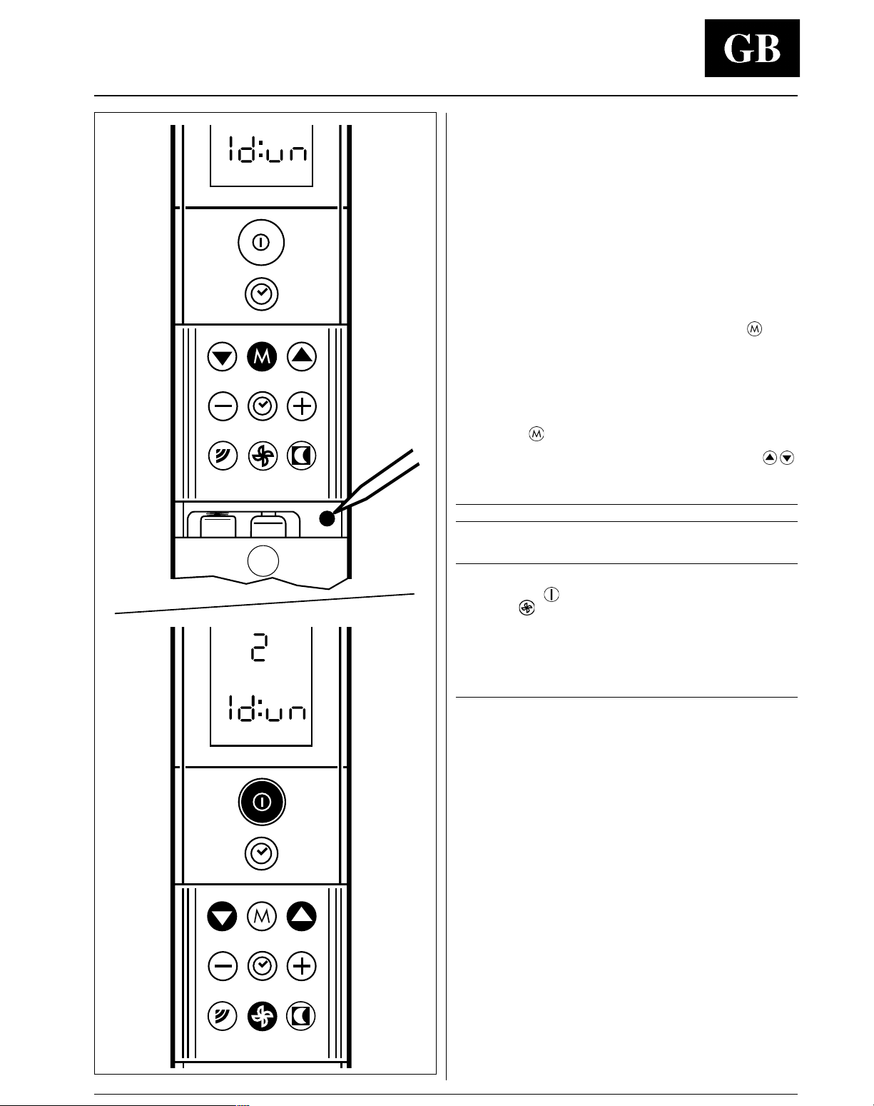
System configuration
Once the electrical connections have been completed, enter
the system configuration.
Check the correct switch position (see "Electrical connection")
(models without electric heater). Incorrect positioning of the
switch causes major system operation problems.
For information on the remote controller refer to the operation
and maintenance manual.
To configure the system proceed as follows:
• Place batteries in the controller, observing the polarity direction
indicated.
• Energize the system by switching main switch in the ON position.
• Press the button for the selection of the operating mode
together with the button for the clock time adjustment for at least
two seconds (the latter is recessed and located next to the battery
compartment, use a pointed tool to activate).
• The controller readout will display the letters “ld:un”.
• If the controller readout will display the letters “CA:P” or “Ad:dr”,
press button
until the letters “ld:un” will be displayed.
• Now, by pressing buttons for the temperature adjustment
display one of the figures shown in the following table according
to the model size in use.
Model size Figure to select
07 - 09 - 12 1
18 - 24 2
• To send the transmission of the message to the unit, press the
starting button
, and then the button for the selection of the
fan speed
for at least two seconds.
• The controller will automatically turn off and configuration is
completed.
Operating test
• Energize the system by putting the mains supply switch to the ON
position.
• Position the operating switch located in the electrical board inside
the unit on “Test”.
1) The air conditioner will operate in the cooling mode for a
maximum period of 30 minutes without thermostatic control of
the room temperature and without the time delay protection
against frequent compressor cycling.
2) The air distribution louver will operate in the “SWING” mode.
3) Red indicator on the unit will light up.
• During test operation, the installer must check that the 3
conditions above are fulfilled.
• Slide the switch under the unit panel from the “Test” to the
“Normal” position to exit test program.
• During the test program, any signal sent to the unit by the remote
controller will stop the test and put the air conditioner in the mode
shown on display.
42 HWS
Cooling only models Heat pump models
Outdoor unit Indoor unit Outdoor unit Indoor unit
IMQ certification
Your air conditioning system has been awarded IMQ certification.
The certification of the institute is only valid for systems consisting of the outdoor and indoor models listed below.
Note:
It is possible to have both the active carbon filter and passive electrostatic filter installed together in the unit.
Table IV: Accessories
Mod. 42HWS
Description Part number
07 09 12 18 24
42HWX 900---102-40
앬앬앬
Active carbon filter
42HWX 900---100-40
앬앬
42HWX 900---103-40
앬앬앬
Passive electrostatic filter
42HWX 900---101-40
앬앬
Guide for the owner , accessories and IMQ certification
Guide for the owner
When installation and tests are completed explain the Operation
and Maintenance Manual to the owner, with particular attention to
the main operating modes of the air conditioner, such as:
• Turning the unit on and off.
• Functions of the remote control.
• Removal and cleaning of the air filters.
Leave the two installation manuals for the indoor and outdoor units
with the owner for future use during maintenance operations or for
any other needs.
38GL--07---703EC-40
42HWS007---703IJ-40 38YL--07---703EJ-40 42HWS007---703IJ-40
38GLS-07G---703EC-40
38GL--09---703EC-40
42HWS009---703IJ-40 38YL--09---703EJ-40 42HWS009---703IJ-40
38GLS-09G---703EC-40
38GL--12---703EC-40
42HWS012---703IJ-40 38YL--12---703EJ-40 42HWS012---703IJ-40
38GLS-12G---703EC-40
38GL--18---703EC-40
42HWS018---703IJ-40 38YL--18---703IJ-40 42HWS018---703IJ-40
38GLS-18G---703EC-40
38GL--24---703EC-40
42HWS024---703IJ-40 38YL--24---703IJ-40 42HWS024---703IJ-40
38GLS-24G---703EC-40
 Loading...