


40KMC018-7N
Carrier 40KMC018-7N, 40KMC012-7N, 40KMC118-7EN, 40KMC018-3N, 40KMC024-7N Installation Manual
...
A
M
P
M
40KMC---N
INST ALLA TION MANUAL
GB - 1
40KMC---N
Split system “Global cassette” indoor unit
ENGLISH
IR Remote Control “Room Controller” “Zone Manager”
The unit can be used with infrared Remote Control, with the Carrier “Room
Controller” or “Zone Manager”.
Infrared control installation instructions are contained in the unit instruction and
maintenance manual.
Remote controls intallation instructions are contained in the relevant manuals,
supplied with the remote controls.
The operation and maintenance instructions for the indoor unit and the installation
instructions for the indoor and the outdoor unit are given in the manuals for each
unit. These are supplied with the unit.
Contents
Page
Dimensions and weight......................................................................................... 2
T echnical data....................................................................................................... 3
Technical data of electric heaters ......................................................................... 3
Material supplied .................................................................................................. 3
Operating limits..................................................................................................... 3
Components required for a complete installation................................................. 3
General information.............................................................................................. 4
Accessories .......................................................................................................... 4
Warnings: avoid .................................................................................................... 5/6
Installation ............................................................................................................ 6/8
Refrigerant connections ....................................................................................... 9
Electrical connections........................................................................................... 10/14
Fresh air renewal and conditioned air supply to adjacent room........................... 15/16
System configuration............................................................................................ 17
Operating test, address switch and address selector................................. 18
Fault code, button T: “EMERGENCY” and guide for the owner.................. 19
Indoor unit Indoor unit Indoor unit
item number item number 50Hz + item number
Sizes 50Hz electric heater 60Hz
with grille with grille with grille
12 40KMC012-7N 40KMC112-7EN 40KMC012-3N
18 40KMC018-7N 40KMC118-7EN 40KMC018-3N
24 40KMC024-7N 40KMC124-7EN 40KMC024-3N
28 40KMC028-7N 40KMC328-7EN 40KMC028-3N
36 40KMC036-7N 40KMC336-7EN 40KMC036-3N
48 40KMC048-7N 40KMC348-7EN 40KMC048-3N
60 40KMC060-7N 40KMC360-7EN 40KMC060-3N
40KMC---N
GB - 2
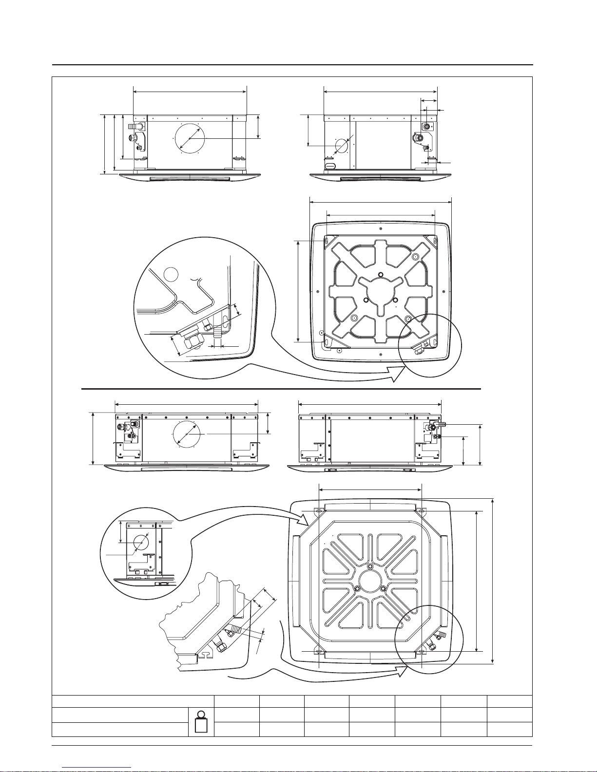
Dimensions and weight
40KMC---7N 012 018 024 028 036 048 060
Unit 17,5 19 19 36 38 38 41
Frame / Grille assembly 3335555
kg
575
298
120
225
280
56
52
91
575
158
720
550
515
Ø 150
Ø 70
50
30
Ø 25
813
595
825
120
298
168
237
960
825
Ø 150
66
48
Ø 25
Ø 100
150
40KMC 028N - 036N - 048N - 060N
40KMC 012N - 018N - 024N
40KMC---N
GB - 3
ENGLISH
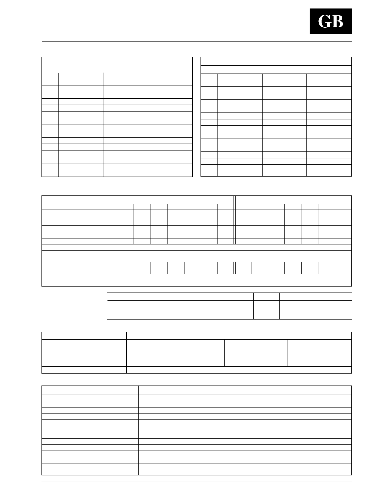
T echnical data
Note: For power supply wire size and delay type fuses, refer to the outdoor unit installation instructions.
Table I: Nominal data
POWER INPUT (WATT)
Cooling only
Sizes standard Cooling Heating
12 40KMC012-7N 75 75
18 40KMC018-7N 80 80
24 40KMC024-7N 105 105
28 40KMC028-7N 107 107
36 40KMC036-7N 131 131
48 40KMC048-7N 178 178
60 40KMC060-7N 231 231
Sizes with electric heaters Cooling Heating
12
40KMC112-7EN
75 1575
18
40KMC118-7EN
80 2580
24
40KMC124-7EN
105 2605
28
40KMC328-7EN
107 3107
36
40KMC336-7EN
131 3131
48
40KMC348-7EN
178 3178
60
40KMC360-7EN
231 3231
POWER INPUT (WATT)
Heat pump
Sizes standard Cooling Heating
12 40KMC012-7N 75 75
18 40KMC018-7N 80 80
24 40KMC024-7N 105 105
28 40KMC028-7N 107 107
36 40KMC036-7N 131 131
48 40KMC048-7N 178 178
60 40KMC060-7N 231 231
Sizes with electric heaters Cooling Heating
12
40KMC112-7EN
75 1575
18
40KMC118-7EN
80 1580
24
40KMC124-7EN
105 1605
28
40KMC328-7EN
107 2107
36
40KMC336-7EN
131 2131
48
40KMC348-7EN
178 2178
60
40KMC360-7EN
231 2231
Table II: Technical data of electric heaters (if installed)
Heat pump Cooling only
Mod. 12 18 24 28 36 48 60 12 18 24 28 36 48 60
Electric heater kW 1.5 1.5 1.5 2 x 1.0 2 x 1.0 2 x 1.0 2 x 1.0 1.5 1.5 1.5 2 x 1.0 2 x 1.0 2 x 1.0 2 x 1.0
++++++
capacity
1.0 1.0 2 x 0.5 2 x 0.5 2 x 0.5 2 x 0.5
Supply voltage V 230 230 230 230 230 230 230 230 230 230 400 400 400 400
(*) (*) (*) (*) (*) (*) 3N 3N 3N 3N
Max. current draw A 6.5 6.5 6.5 8.8 8.8 8.8 8.8 6,5 10.8 10.8 7.5 7.5 7.5 7.5
Control device GMC electronic control
Safety thermostat
N° 1
Manual reset thermostat
ST1 60°C
N° 1
Manual reset thermostat
ST2 100°C
Power supply cables mm23 G 1.5 3 G 1.5 3 G 1.5 4 G 1.5 4 G 1.5 4 G 1.5 4 G 1.5 3 G 1.5 3 G 2.5 3 G 2.5 5 G 1.5 5 G 1.5 5 G 1.5 5 G 1.5
Recommended fuse (gL type) A 88888888121210101010
*
In areas with a 2 kW limit for single-phase electric heaters it is possible to divide the power supply on two phases and neutral of a three phase supply with neutral.
Use cable type
H07 RN-F - 4G1,5 mm2 - 400V 2N ~
T able III:
Material supplied
Description Quantity Use
Installation instructions 1 Indoor unit installation
Owner's Manual 1 Correct use
Fresh air intake baffle 1 Air renewal
Table IV: Operating limits
Cooling / Heating Refer to outdoor unit installation manual.
Nominal single-phase voltage 230V ~ 50Hz 230V-240V ~ 60Hz
Main power supply Operating voltage limits min. 198V – max. 264V
Nominal three-phase voltage 400V 3N~ 50Hz
Operating voltage limits min. 342V – max. 462V
Electric heater 27
°C
T able V : Components required for a complete installation
Name Specification
Connection pipe
40KMC 012N Ø (1/2") 12.70 mm (Gas) / Ø (1/4") 6.35 mm (Liquid)
40KMC 018N, 024N, 028N, 036N, 048N and 060N Ø (1/2") 12.70 mm (Gas) / Ø (1/4") 6.35 mm (Liquid)
Wall sleeve
Wall cap
Finishing tape PVC film
Fastening tape
Tube insulation
Drain hose
I.D. 16 - 17 mm
Sealer putty
- Outdoor power supply cable H07 RN-F (60245IEC66),
cable with synthetic rubber insulation and polychloroprene sheath.
- Electrical connecting cable H07 RN-F (60245IEC66),
between indoor and outdoor unit cable with synthetic rubber insulation and polychloroprenesheath.
40KMC---N
GB - 4
Unit installation
Read this instruction manual thoroughly before starting
installation.
• This unit complies with the low-voltage (EEC/73/23) and
electromagnetic compatibility (EEC/ 89/336) directives.
• Follow all current national safety code requirements.
In particular ensure that a properly sized and connected ground
wire is in place.
• Check that the voltage and frequency of the mains power supply
are as required for the unit to be installed; the available power
source must be adequate to operate all other appliances
connected to the same line.
Also ensure that national safety code requirements have been
followed for the main supply circuit.
• Connection of the system to the mains power supply is to be
carried out in compliance with the wiring diagram shown in
the installation instructions of the external section.
• Connect indoor and outdoor units with field-supplied copper
pipes by means of flare connections. Use insulated seamless
refrigeration grade pipe only, (Cu DHP type according to
ISO1337), degreased and deoxidized, suitable for operating
pressures of at least 4200 kPa and for burst pressure of at least
20700 kPa. Under no circumstances must sanitary type copper
pipe be used.
• Where necessary, use field-supplied 25 mm I.D. PVC pipe (not
supplied) of appropriate length and with the correct thermal
insulation for the condensate drain extension.
• After installation thoroughly test system operation and explain all
system functions to the owner.
• Use this unit only for factory approved applications: the unit
cannot be used in laundry or steam pressing premises.
WARNING:
Disconnect the mains power supply switch before servicing
the system or handling any internal parts of the unit.
• Do not open the remote control to avoid possible damage. In case
of malfunctioning contact a qualified service engineer.
• This installation manual describes the installation procedures of
the indoor unit of a residential split system consisting of two
Carrier manufactured units.
Do not connect this unit to any other manufacturer's outdoor unit.
The manufacturer declines any liability for system malfunction
resulting from unauthorised system combinations.
• The manufacturer declines any liability for damage resulting
from modifications or errors in the electrical or refrigerant
connections.
Failure to observe the installation instructions, or use of the
unit under conditions other than those indicated in table
General information
“Operating limits” of the outdoor unit installation manual, will
immediately invalidate the unit warranty.
• Failure to observe electric safety codes may cause a fire hazard in
the event of short circuits.
• Inspect equipment for damage during transport. In case of
damage file an immediate claim with the shipping company.
Do not install or use damaged units.
• In case of malfunction turn the unit off, disconnect the mains
power supply and contact a qualified service engineer.
• Maintenance of the refrigerant circuit must only be carried out by
qualified personnel.
• All of the manufacturing and packaging materials used for this
appliance are biodegradable and recyclable.
• Dispose of the packaging material in accordance with local
requiremements.
• This equipment contains refrigerant that must be disposed of
correctly.
When disposing of the unit at the end of its operational life,
take the unit to an authorised waste disposal centre, or to the
original equipment dealer, for correct disposal.
Choosing the installation site
Positions to avoid:
• Exposure to direct sunlight.
• Areas close to heat sources.
• On damp walls or in positions that may be exposed to water
hazard.
• Where curtains or furniture may obstruct free air circulation.
Recommendations:
• Choose an area free from obstructions which may cause uneven
air distribution and/or return.
• Consider using an area where installation is easy.
• Choose a position that allows for the clearances required.
• Look for a position in the room which ensures the best possible air
distribution.
• Install unit in a position where condensate can easily be piped to an
appropriate drain.
Notes:
(1)
Not to be used on units equipped with electric heater.
(2)
IMQ approved kit.
T able VI: Accessories A= mod. 012, 018, 024. B= mod. 028, 036, 048, 060.
Description Code A B
Air supply outlet obstruction kit
(1)
40GK-900---003-40 X
40GK-900---013-40 X
Room Controller kit (Grouping) 33MC9002 X X
Zone manager kit (Zoning) 33MC9001 X X
Zone manager 33MC-ZM X X
Infrared control kit
(2)
33MC-MC X X
Description Code A B
Electrostatic filter
40GK-900---001-40 X
40GK-900---011-40 X
Active carbon filter
40GK-900---002-40 X
40GK-900---012-40 X
Room Controller 33MC-RC X X
GB - 5
40KMC---N
ENGLISH
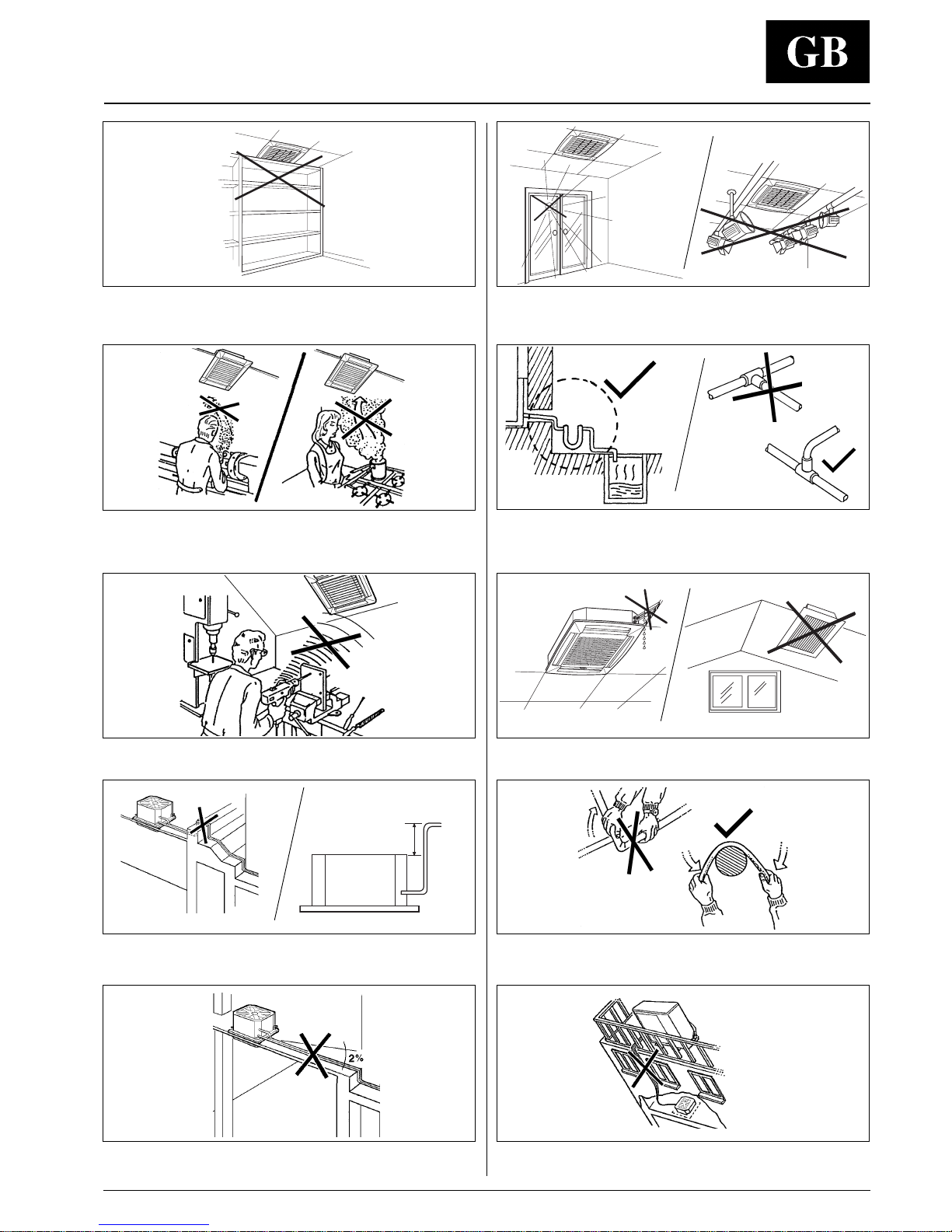
Warnings: avoid...
MAX 200 mm
... any obstruction of the unit air intake or supply grilles.
... exposure to direct sunshine, when the unit is operating in the
cooling mode; always use shutters or shades.
... positions too close to heating sources which may damage the unit.
... ascending sections of condensate drain piping.
These may only be used near the unit with a maximum height
difference of 200 mm from the top of the unit.
... flattening or kinking the refrigerant pipes or condensate pipes.
... installation in areas with high frequency waves. ... only partial insulation of the piping.
Non-level installation which will cause condensate dripping.
... exposure to oil vapours.
... connecting condensate piping to sewage system drain without
appropriate trap. Trap height must be calculated according to the
unit discharge head in order to allow sufficient and continuous
water evacuation.
... horizontal sections or curves of condensate drain piping with less
than 2% slope.
... excessive height difference between outdoor and indoor units
(see installation manual of outdoor unit).
40KMC---N
GB - 6
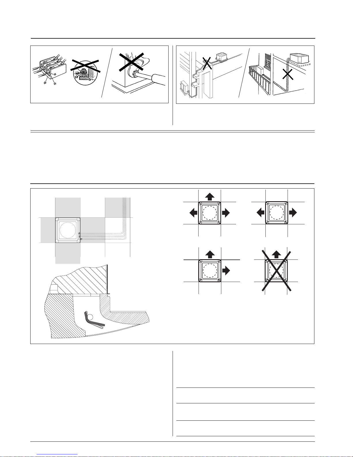
Max. 2 louvres closed
Heat pump: louvre position for correct air flow
Cooling: louvre position for correct air flow
Warnings: avoid...
... unnecessary turns and bends in connection pipes (see
installation manual of outdoor unit).
Excessive connection pipe length (see installation manual of
outdoor unit).
... slack on electrical connections.
... disconnecting refrigerant connections after installation: this will
cause refrigerant leaks.
Installation
• In order to allow easy and rapid installation and maintenance,
make sure that in the selected position it is possible to remove
the ceiling panels or, if the ceiling is constructed using
masonry, that access to the unit is guaranteed.
ATTENTION:
Only restrict the air outlets as indicated in the drawing.
WARNING:
To close one or two air outlets use the special kit.
• Install the unit as centrally as possible in the room, the air flow
direction can be controlled by means of the remote control
(where used) or automatically, according to the operating mode
(cooling or heating): this will ensure optimum distribution of the
air in the room.
• During cooling mode operation the best position for the
deflecting louvres is one which allows air diffusion close to the
ceiling (Coanda effect).
In heating mode, the louvres should be positioned so that the air
is directed towards the floor, in order to prevent layers of hot air
forming in the upper part of the room (this will happen
automatically when the deflecting louvres are positioned in the
“AUTOMATIC” mode).
Alternatively the louvres can be placed in intermediate positions
(with infrared control only) or allowed to move continuously
(SWING).
 Loading...