

Carrier 38AK008, 38AKS009, 38AK012, 38AK007, 38AKS012 User Manual
...
38AK007,008,012
Fig. 1 — Model 38AK (Size 007 Shown)
38AKS008,009,012
Air-Cooled Condensing Units
Installation, Start-Up and
Service Instructions
50/60 Hz
CONTENTS
SAFETY CONSIDERATIONS
INSTALLATION
Step 1 — Complete Pre-Installation Checks
• UNCRATE UNIT
• INSPECT SHIPMENT
• CONSIDER SYSTEM REQUIREMENTS
Step 2 — Rig and Mount the Unit
• RIGGING
• COMPRESSOR MOUNTING
Step 3 — Complete Refrigerant Piping
Connections
• SIZE REFRIGERANT LINES
• FILTER DRIER AND MOISTURE INDICATOR
Step 4 — Make Electrical Connections
• FIELD POWER SUPPLY
• FIELD CONTROL WIRING
START-UP
Preliminary Checks
Compressor Rotation
Evacuate and Dehydrate
Refrigerant Charge
Compressor Overload
Cycle-LOC™ Device (CLO)
Low-Pressure/Loss-of-Charge Switch (LPS)
High-Pressure Switch (HPS)
High Flow Valves
Refrigerant Service Ports
Cooling
Sequence of Operation
Oil Charge
SERVICE
Cleaning
Lubrication
Condenser-Fan Adjustment
Capacity Control — Unit 38AKS012 Only
Compressor Removal
Crankcase Heater (Except 38AK007)
TROUBLESHOOTING GUIDE
START-UP CHECKLIST
. . . . . . . . . . . . . . . . . . . . . . . . . . . . . . . . . . . . . . . . . 10
. . . . . . . . . . . . . . . . . . . . . . . . . . . . . . . . . 1-8
. . . . . . . . . . . . . . . . . . . . . . . . . . . . . . . . . . . 4
. . . . . . . . . . . . . . . . . . . . . . . . . . . . . . . . . . . . . .9-11
. . . . . . . . . . . . . . . . . . . . . . . . . . . . . . 9
. . . . . . . . . . . . . . . . . . . . . . . . . . . . . . . 9
. . . . . . . . . . . . . . . . . . . . . . . . . . . . . . . . 10
. . . . . . . . . . . . . . . . . . . . . . . . . . . . . . . . . . . . . . . 11
. . . . . . . . . . . . . . . . . . . . . . . . . . . . . . . . . . . . . .11,12
. . . . . . . . . . . . . . . . . . . . . . . . . . . . . . . . . . . . . . . . 11
. . . . . . . . . . . . . . . . . . . . . . . . . . . . . . . . . . . . . . 11
. . . . . . . . . . . . . . . . . . . . . . 1
. . . . . . . . . . . . . . . . . 4
. . . . . . . . . . . 6
. . . . . . . . . . . . . . . . . . . . . . . . . . . . 9
. . . . . . . . . . . . . . . . . . . . . . . . . 9
. . . . . . . . . . . . . . . . . . . . . . . . . . . 10
. . . . . . . . . . . . . . . . . . . . . . 10
. . . . . . . . . . . . . . . . . . . . . 10
. . . . . . . . . . . . . . . . . . . . . . . 10
. . . . . . . . . . . . . . . . . . . . . . . . . . 10
. . . . . . . . . . . . . . . . . . . . . 11
. . . . . . . . 12
. . . . . . . . . . . . . . . . . . . . . . . . . . . 12
. . . . . . . . . . . . 12
. . . . . . . . . . . . . . . . . .13,14
. . . . . . . . . . . . . . . . . . CL-1, CL-2
Page
. . . . . . 1
. . . . . 10
Follow all safety codes. Wear safety glasses and work
gloves. Use quenching cloth for brazing operations. Have fire
extinguisher available. Read these instructions thoroughly.
Consult local building codes and National Electrical Code
(NEC) (U.S.A. Standard) for special installation requirements.
Before installing or servicing system, always turn off main
power to system and install lockout tag on disconnect.
There may be more than one disconnect switch. Electrical
shock can cause personal injury.
INSTALLATION
The 38AK007, 008, and 012 units use hermetic compressors. The 38AKS008, 009, and 012 units use semi-hermetic
compressors. See Table 1A or 1B for physical data.
Step 1 — Complete Pre-Installation Checks
UNCRATE UNIT (S ee Fig. 1) — Remove unit packaging
except for the top skid assembly and wood bumpers, which
should be left in place until after unit is rigged into place.
INSP E C T SHI PM E N T — File claim with shipping company
if shipment is damaged or incomplete.
SAFETY CONSIDERATIONS
Installing and servicing air-conditioning equipment can be
hazardous due to system pressure and electrical components.
Only trained and qualified service personnel should install or
service air-conditioning equipment.
When working on air-conditioning equipment, observe precautions in literature and on tags and labels attached to unit.
NOTE: Ensure voltage listed on unit data plate agrees with
electrical supply to unit.
Manufacturer reserves the right to discontinue, or change at any time, specifications or designs without notice and without incurring obligations.
Book 1 4
Ta b 3 a 2 a
PC 111 Catalog No. 533-80003 Printed in U.S.A. Form 38A-9SI Pg 1 5-01 Replaces: 38A-8SI

Table 1A — Physical Data — 50/60 Hz (English)
UNIT 38 AK007 AK008 AK012 AKS008 AKS009 AKS012
OPERATING WEIGHT (lb)
Aluminum Coils (Standard)
Copper Coils (Optional)
RIGGING WEIGHT (lb)
Aluminum Coils (Standard)
Copper Coils (Optional)
REFRIGERANT*
COMPRESSOR
Bristol, Reciprocating Copeland, Scroll Copeland, Scroll Reciprocating, Semi-Hermetic
Quantity...Type
Quantity Cylinders
Speed (rpm) — 60 Hz
— 50 Hz
Oil Charge (oz)
CONDENSER FAN — 60 Hz
Quantity...Rpm
Diameter (in.)
Motor Hp (NEMA)
Nominal Airflow (cfm)
CONDENSER FAN — 50 Hz
Quantity...Rpm
Diameter (in.)
Motor Hp (NEMA)
Nominal Airflow (cfm)
CONDENSER COIL
Face Area (sq ft)
Storage Capacity (lb)†
CONNECTIONS (sweat)
Suction (in.)
Liquid (in.)
CONTROLS
Pressurestat Settings (psig)
High Cutout
Cut-in
Low Cutout
Cut-in
LEGEND
NEMA —
*Unit is factory supplied with holding charge only.
†Storage capacity of condenser coil with coil 80% full of liquid R-22 at 124 F.
National Electrical Manufacturing Association
NOTE: Unit 38AKS012 has one step of unloading. Full load is 100% capacity, and one
step of unloading is 67% capacity. Unit 38AKS012 has the following unloader settings:
load is 70 ± 1 psig and unload is 60
±
340 392 426 510 564 564
386 460 503 578 632 632
390 442 476 560 614 614
436 510 553 628 682 682
1...H26A72Q 1...ZR94KC 1...ZR125KC 1...06DA818 1...06DA824
2——4 6
3500 3500 3500 1750 1750
65 85 110 88 128
Propeller; Direct Drive
1...850 1...1100
26 26
1
/
3
3800 6500 7000 6500 6500 6500
Propeller; Direct Drive
3150 5400 5800 5400 5400 5400
Enhanced Copper Tubes, Aluminum Lanced Fins
12.24 15.75 20.5 18.0 18.0 18.0
11.26 14.88 18.87 16.56 16.56 16.56
1
/
1
8
1
/
2
11/
8
1
/
2
426 ± 7
320 ± 20
2 psig.
R-22
1...960
26
1
/
3
11/
8
5
/
8
7 ± 3
22 ± 5
1460 1460
3
/
4
11/
1
8
/
2
11/
5
/
8
8
1...06DH824
(See Note)
11/
8
5
/
8
2

Table 1B — Physical Data — 50/60 Hz (SI)
UNIT 38 AK007 AK008 AK012 AKS008 AKS009 AKS012
OPERATING WEIGHT (kg)
Aluminum Coils (Standard)
Copper Coils (Optional)
RIGGING WEIGHT (kg)
Aluminum Coils (Standard)
Copper Coils (Optional)
REFRIGERANT*
COMPRESSOR
Bristol, Reciprocating Copeland, Scroll Copeland, Scroll Reciprocating, Semi-Hermetic
Quantity...Type
Quantity Cylinders
Speed (r/s) — 60 Hz
— 50 Hz
Oil Charge (L)
CONDENSER FAN — 60 Hz
Quantity...R/s
Diameter (mm)
Motor Hp (NEMA)
Nominal Airflow (L/s)
CONDENSER FAN — 50 Hz
Quantity...R/s
Diameter (mm)
Motor Hp (NEMA)
Nominal Airflow (L/s)
CONDENSER COIL
Face Area (sq m)
Storage Capacity (kg)†
CONNECTIONS (sweat)
Suction (in.)
Liquid (in.)
CONTROLS
Pressurestat Settings (kPa)
High Cutout
Cut-in
Low Cutout
Cut-in
LEGEND
NEMA —
*Unit is factory supplied with holding charge only.
†Storage capacity of condenser coil with coil 80% full of liquid R-22 at 51 C.
National Electrical Manufacturing Association
NOTES:
1. Unit 38AKS012 has one step of unloading. Full load is 100% capacity, and one
step of unloading is 67% capacity. Unit 38AKS012 has the following unloader
settings: load is 483 ± 6.9 kPa and unload is 414 ± 13.8 kPa.
2. Equivalent mm values for connectors are as follows:
in.
1
/212.7
5
/815.9
1
/828.6
1
mm
154 177 192 231 256 256
175 208 215 262 287 287
176 200 215 254 279 279
198 231 250 285 309 309
1...H26A72Q 1...ZR94KC 1...ZR125KC 1...06DA818 1...06DA824
2——4 6
58.4 58.4 58.4 29.2 29.2
48.4 48.4 48.4 24.2 24.2
1.92 2.51 3.25 2.60 3.78
Propeller; Direct Drive
1...14.2 1...18.3
660 660
1
/
3
1800 3050 3300 3050 3050 3050
Propeller; Direct Drive
1490 2550 2750 2550 2550 2550
Enhanced Copper Tubes, Aluminum Lanced Fins
1.14 1.46 1.90 1.67 1.67 1.67
5.1 6.75 8.6 7.5 7.5 7.5
1
/
1
8
1
/
2
11/
8
1
/
2
R-22
1...16.0
660
1
/
3
11/
8
5
/
8
2937 ± 48
2206 ± 138
48 ± 20
151 ± 34
1...06DH824
(See Note 1)
3
/
4
11/
8
1
/
2
11/
8
5
/
8
11/
8
5
/
8
3

CONSIDER SYSTEM REQUIREMENTS
• Consult local building codes and NEC for special installation requirements.
• Allow sufficient space for airflow clearance, wiring,
refrigerant piping, and unit servicing. See Fig. 2.
• Locate unit so that condenser airflow is unrestricted on
all sides and above. Refer to Fig. 2.
• Unit may be mounted on a level pad directly on base
rails or mounted on raised pads at support points. See
Table 2 for weight distribution based on recommended
support points.
NOTE: If vibration isolators are required for a particular installation, use corner weight information in Table 2 to make
proper selection.
Table 2 — Weight Distribution
UNIT
38AK
007
008
012
S008
S009,S012
007
008
012
S008
S009,S012
STD UNIT
Lb Kg Lb Kg Lb Kg Lb Kg Lb Kg
340 154 86 39 53 24 77 35 124 56
392 177 86 39 78 35 99 45 107 49
426 192 89 40 92 42 109 49 105 48
510 231 115 52 89 40 133 60 173 87
564 256 133 60 97 44 141 64 193 88
386 175 106 48 65 30 82 37 133 60
460 208 114 52 95 43 108 49 121 55
503 215 118 53 116 53 119 54 119 54
578 262 143 65 106 48 142 64 187 85
632 287 161 73 114 52 150 68 207 94
CORNERWCORNERXCORNERYCORNER
With Aluminum Coil
With Copper Coil
Z
Raise from above to lift unit from rails or pad when unit is
in final position.
After unit is in position, remove all shipping materials and
top crating.
COMPRESSOR MOUNTING — Compressors are shipped
from the factory held down by 4 bolts. After unit is installed,
loosen each bolt until the snubber washer can be moved with
finger pressure. See Fig. 4.
Step 3 — Complete Refrigerant Piping Connections —
cap; liquid connection is sweat with plastic cap. Refer to
Table 3A or 3B for the proper line sizes. Follow standard
piping practices.
SIZE REFRIGERANT LINES — Consider length of piping
required between condensing unit and air handler, amount of
liquid lift, and compressor oil return. See Table 4A and 4B and
also refer to Part 3 of Carrier System Design Manual for design
details and line sizing. Refer to air handle r instal lation instructions for additional information.
Table 3A — Refrigerant Piping Sizes — 60 Hz
UNIT
38
AK007
AK008
AK012
AKS008
AKS009
AKS012
LEGEND
Liquid LIne
L—
Suction Line
S—
Suction connection is sweat with plastic
LINEAR LENGTH OF PIPING — FT (M)
0-25
(0-7.6)
LSLSLSLS
1
1
/
2
1/
1
2
5
1
/
8
1
1
/
2
5
1
/
8
5
1
/
8
1
/
8
1
/
8
1
/
8
1
/
8
1
/
8
1
/
8
25-50
(7.6-15.2)
1
/
2
1
/
2
5
/
8
1
/
2
5
/
8
5
/
8
50-75
(15.2-22.9)
Line Size (in. OD)
1
1
1
/
/
8
2
1
5
1
/
/
8
8
3
5
1
/
/
8
8
1
5
1
/
/
8
8
1
5
1
/
/
8
8
1
5
1
/
/
8
8
1
1
/
1
1
/
3
1
/
1
1
/
3
1
/
3
1
/
(22.9-30.5)
1
8
5
8
5
8
5
8
5
8
5
8
75-100
/
2
/
8
/
8
/
8
/
8
/
8
1
1
1
1
1
1
1
/
8
3
/
8
3
/
8
3
/
8
3
/
8
3
/
8
NOTES:
1. Dimensions in [ ] are in millimeters.
2. See Fig. 3 for additional information.
Step 2 — Rig and Mount the Unit
Be sure unit panels are securely in place prior to rigging.
RIGG ING — These units are designed for overhead rigging.
Refer to rigging label for preferred rigging method. Spreader
bars are not required if top crating is left on unit. All panels
must be in place when rigging. (See Fig. 3.) As further protection for coil faces, plywood sheets may be placed against sides
of unit, behind cables. Run cables to a central suspension point
so that angle from the horizontal is not less than 45 degrees.
Raise and set unit down carefully.
If it is necessary to roll unit into position, mount unit on
rails, using a minimum of 3 rollers. Apply force to rails, not
unit. If unit is to be skidded into position, place it on a large pad
and drag it by the pad. Do not apply any force to unit.
Table 3B — Refrigerant Piping Sizes — 50 Hz
LINEAR LENGTH OF PIPING — FT (M)
0-25
UNIT
(0-7.6)
38
LSLSLSLS
1
1
AK007
AK008
AK012
AKS008
AKS009
AKS012
/
2
1
1
/
2
5
1
/
8
1
1
/
2
5
1
/
8
5
1
/
8
LEGEND
Liquid LIne
L—
Suction Line
S—
NOTES FOR TABLES 3A AND 3B:
1. Pipe sizes are based on a 2 F (1 C) loss for liquid and suction
lines.
2. Pipe sizes are based on the maximum linear length shown for
each column, plus a 50% allowance for fittings.
3. Charge units with R-22 in accordance with unit installation
instructions.
4. Line size conversion to mm is:
mm
in.
1
/
12.7
2
5
/
15.9
8
1
/828.6
1
3
1
/834.9
1
/
8
1
/
8
1
/
8
1
/
8
1
/
8
1
/
8
25-50
(7.6-15.2)
1
/
2
1
/
2
5
/
8
1
/
2
5
/
8
5
/
8
50-75
(15.2-22.9)
Line Size (in. OD)
1
1
1
/
/
8
2
1
5
1
/
/
8
8
3
5
1
/
/
8
8
1
5
1
/
/
8
8
1
5
1
/
/
8
8
1
5
1
/
/
8
8
1
1
/
3
1
/
3
1
/
3
1
/
3
1
/
3
1
/
(22.9-30.5)
1
8
5
8
5
8
5
8
5
8
5
8
75-100
/
2
/
8
/
8
/
8
/
8
/
8
1
1
/
8
3
1
/
8
3
1
/
8
3
1
/
8
3
1
/
8
3
1
/
8
4
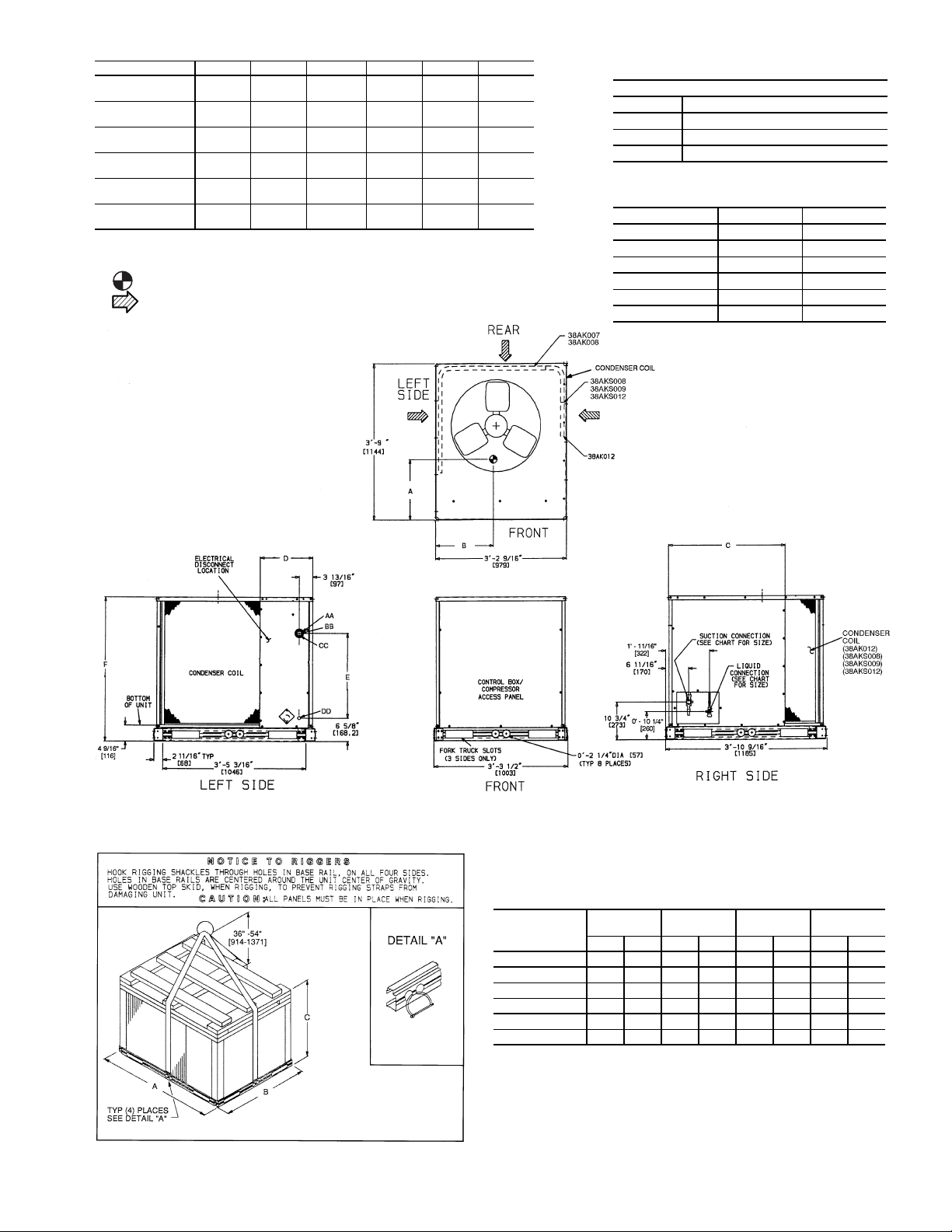
UNIT 38 DIM. A DIM. B DIM. C DIM. D DIM. E DIM. F
AK007
AK008
AK012
AKS008
AKS009
AKS012
NOTES:
1. Dimensions in [ ] are in millimeters.
2. Center of Gravity. See chart for
3. Direction of Airflow.
4. Minimum clearance (local codes or jurisdiction
5. With the exception of the clearance for the con-
6. Units may be installed on combustible floors
dimensions.
may prevail):
a. Condenser coil, for proper airflow, 36 in. [914]
one side, 12 in. [305] the other. The left or rear
side getting the greater clearance is optional.
b. Overhead, 60 in. [1524] to assure proper con-
denser fan operation.
c. Between units, control box side, 42 in. [1067]
per NEC (National Electrical Code) (U.S.A.
Standard).
d. Between unit and ungrounded surfaces, con-
trol box side, 36 in. [914] per NEC.
e. Between unit and block or concrete walls and
other grounded surfaces, control box side,
42 in. [1067] per NEC.
denser coil as stated in Note 4b, a removable
fence or barricade requires no clearance.
made from wood or Class A, B, or C roof covering
material.
1
1′-6
[470.0]
1′-8″
[508.0]
1′-9″
[533.4]
1′-6″
[457.2]
1′-7″
[482.6]
1′-7″
[482.6]
/2″
1′-23/4″
[375.0]
1
/2″
1′-6
[470.0]
1′-8″
[508.0]
3
1′-4
/4″
[425.5]
1′-5″
[431.8]
1′-5″
[431.8]
—
—
—
—
2′-0″
[609.6]
2′-913/16″
[858.8]
13
2′-9
/
16
[858.8]
13
2′-9
/16″
[858.8]
″
1′-21/4″
[362]
1′-3″
[381]
1′-3″
[381]
1′-3″
[381]
1′-3″
[381]
1′-3″
[381]
1′-45/16″
[415]
5
/16″
2′-
[613]
5
/16″
2′-
[613]
2′-5/16″
[613]
5
2′-
/
[613]
2′-5/16″
[613]
ELECTRICAL CONNECTIONS
2′-95/16″
[846.5]
7
/16″
3′-5
[1052.5]
3′-57/16″
[1052.5]
3′-57/16″
[1052.5]
7
″
3′-5
″
16
/
16
[1052.5]
3′-57/16″
[1052.5]
AA 1
BB 2″ Dia [51] Power Supply Knockout
CC 2
DD
SERVICE VALVE CONNECTIONS — 50/60 Hz
UNIT 38 SUCTION LIQUID
AK007 1
AK008 1
AK012 1
AKS008 1
AKS009 1
AKS012 1
CONNECTION SIZES
3
/8″ Dia [35] Field Power Supply Hole
1
/2″ Dia [64] Power Supply Knockout
7
/8″ Dia [22] Field Control Wiring Hole
1
/8″ [28.6] 11/2″ [12.7]
1
″ [28.6] 1
/
8
1
″ [28.6] 1
/
8
1
″ [28.6] 1
/
8
1
″ [28.6] 1
/
8
1
″ [28.6] 1
/
8
1
/
2
5
/
8
1
/
2
5
/
8
5
/
8
″ [12.7]
″ [15.9]
″ [12.7]
″ [15.9]
″ [15.9]
Fig. 2 — Dimensions (ft-in.)
UNIT
38
AK007 390 176 45.0 1143 38.5 978 35.5 904
AK008 442 200 45.0 1143 38.5 978 43.5 1105
AK012 476 215 45.0 1143 38.5 978 43.5 1105
AKS008 560 254 45.0 1143 38.5 978 43.5 1105
AKS009 614 279 45.0 1143 38.5 978 43.5 1105
AKS012 614 279 45.0 1143 38.5 978 43.5 1105
*Weights are for aluminum coils.
Fig. 3 — Rigging Label
5
RIGGING
WEIGHT*
ABC
lb kg in. mm in. mm in. mm
 Loading...