

Page 1
Carrier
«>
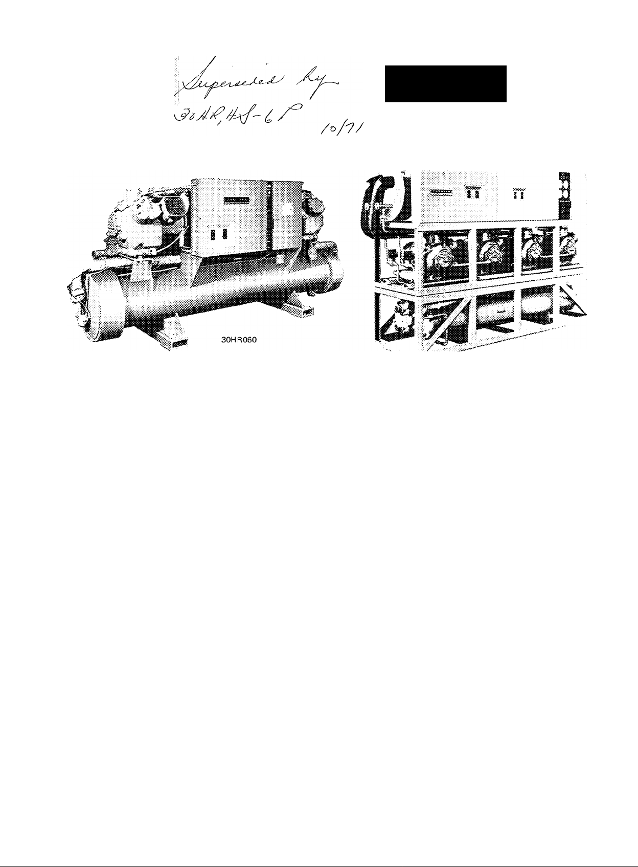
30HR,HS040, 050,060
Hermetic Reciprocating Compressors 40 thru 160 Tons
зон R160
30HR,HS070thru 160
DESCRIPTION
These modern multiple-compressor liquid chilling pack
ages offer all the conveniences and economy of packaged
design, for use in chilled water air-conditioning systems and
various types of process cooling applications. Every
machine is completely factory engineered and assembled to
ensure a perfectly balanced refrigeration system. All com
ponents are matched to perform with high efficiency and
low power consumption. Only external water and electrical
connections must be completed to make the water-cooled
unit operational. Condenserless models require, in addition,
only refrigerant line connections to the remote condenser.
The water-cooled model (30HR) is a complete onepackage system with two condensers having built-in sub
coolers, and a direct expansion cooler with two refrigerant*,
circuits, one for each condenser.
FEATURES
• Low Inrush and Running Current because of sequential
starting and stopping Multiple Compressors*.
• Easy to Service bolted-hermetic compressors.
• Wide Range of Distribution Voltages (208 v to 600 v)
allowed by Carrier Voltage Standards*.
• Protection against Single-Phasing of compressor motors,
assured by manual reset, magnetic-trip circuit breakers.
• Internal Motor Protection against overheating, provided
by quick-sensing elements embedded in motor windings.
• Optimum Control of Chilled Water Temperature for
closer Capacity Control provided by Multiple-Step
Controller.
Model 30HS is a condenserless 30HR, designed for use
with remote water-cooled, air-cooled or evaporative type
condensers Includes all features of the 30HR.
Multiple serviceable compressors are mounted on spring
vibration isolators to minimize sound and vibration trans
mission to the unit frame and the building structure.
Hot-gas mufflers dampen compressor gas pulsations, giving
smooth, quiet operation.
Each refrigerant circuit includes a thermal expansion
valve, a liquid line solenoid valve, a filter-drier and
combination liquid line sight glass and moisture indicator.
Compact construction allows passage thru 36-inch door
way. Little floor space required for installation.
• Balanced Wear on Compressors assured by manual
transfer switch, which changes the lead compressor in the
starting sequence.
• Increased System Capacity, without raising horsepower
requirements, afforded by refrigerant subcooling.
• Protection against Refrigerant Migration and Oil Dilution
provided by compressor crankcase heaters, which are on
during compressor off cycle.
• Reduced Power Costs because of partial load operation
at higher suction temperatures made possible by two
separate refrigerant circuits.
©Carrier Corporation 1969
^Single feature sheet available
Form 30HR,HS-5P
Page 2
>
ACCESSORIES
• Oil Pressure Safety Switch Package available for water-cooled
units (standard on air-cooled units)
• Condenser Manifold Package, available for all 30HR units except
30HR160, provides common inlet and outlet water connections
Package contains two steel manifolds, each in two sections Field
welding required
• Control Circuit Transformer, field-installed, provides 115-volt
secondary ciicuit if separate source is not available
• Chilled Water Flow Switch prevents compressors from operating
unless water is flowing
• Unit Enclosure Panels, with fiber glass insulation, completely
enclose compressor and condenser section.
PHYSICAL DATA
UNIT PHYSICAL DATA
UNIT 30HR,HS
APPROX OPER HR
WT (lb)* HS
REFRIG CHG HR
(R-22)t HS 44 55 64 78 88 98
COMPRESSOR 06Et
% Cap.^ Ckt 1
Ckt 2
No. Control Steps
Total Cylinders
Total Oil Chg (pt)
CONDENSER 09RP 30HR Units Only
Ckt 1
Ckt 2
REFRIG CONN, (in.) N
Liquid
Discharge
040 050
2747 3186
1820 2210
79 94 5 99
55 60 50 57
45
4
8
28
022 027
022
2 % 2 Vs 2 y
2 ly» 2..iy
40 50
4
10
33 38 47 52 57
022 027 033 033
060 070 080 090 100 no
3313
2280
4
12
027
2 ly
4940
3470 3525 3585 4470
1 16 131 141 164 174
Reciprocating Semihermet
43
14 16
043
1 iy¡
5125
62 5
37 5
7
1
1. ly
7
054
iVs; 1
o. Size
y
5350
67 50 55 50
33 50
7 8 8
18
070 054
033
1 2y
1 ly
6400 6525 6655
1 13 122 132 148
c - 1750
20 22
66 71
054 054
2 ly
4530
rpm
45 50 50
070
2 ly
1 2 y
1 ly
120
7580
4590 5290
183 198
8
24
76 76
070
070 070
2 2 y
140
8000
5400
50 50
4
24 24
070
2
y
2. 2Vs
160
220
168
50
4
76
084
084
*lncludes refrigerant operating charge.
tSOHR shipped with full oper charge, 30HS shipped with holding
charge (charge for remote condenser and interconnecting piping
added in field).
COOLER PHYSICAL DATA
UNIT 30HR.HS
SHELL, Net Vol
(gal.)
OD (ft-in.)
Length (ft-in.)
TUBES
Number
Length (ft-in.)
Outside Area
(sq ft)
REFRIG CIRCUITS
REFRIG PASSES
MAX DESIGN WKG
PRESS, (psig)
050,060
040
23 6 36 5
0-1 oy 0-12y
6- 0V4
7- 6
200 294
6-2V2 7-8 y
158 284
070,080,
Prime Surface
6-ll’/i6
Refrigerant Side - 235
Water Side - 250
100,110,
090
1-4 1-6 1-6
6-9 7-6
Copper
488
7-87.6
440 645 762
140,160
120
50 0 52 7
646 646
9-2%
2
2
WATER CONN. (In.)
Inlet and Outlet*
Drain
*ASA flat-face flange
3
1
4
1
5
1
9-0
ifSee Electrical Data table for sizes and usage.
CONDENSER PHYSICAL DATA
(^DENSER 09RP
00
Length
TUBES
Number
• Length (ft-in.)
022 1 027 033 043 1 054
i-oy
3-1 oy0-1 oy
5-10 5-10 5-10 5-10 7-2
45
5-lOy.
0-1 oy
Integral Fi
56 64 84 84
5-1073 2
1-oy 1-oy
n, 19 Fins/in.
070 084
1-2
7-2 7-2
124
105
7-27«
Area
Inside (sq ft)
Outside (sq ft)
44 8 51 2 66 8 82.8
36
145 166 217 268
117
103.5 121.5
336 394
SUBCOOLERTUBES
Number
Length (ft-in.)
5 5 5 9
5
5-10732
5-10732
7-2 y
Area
Inside (sq ft)
Outside (sq ft)
6
1
WATER CONN. (in.F
Inlet
Outlet
4 C 4 0 4 9 8 8
4,0
13 0 13 0
13 0
272 3 3
272
2V2
272
272
272
3
15.9
3 4
28 5
2721
WATER PASSES
MAX DESIGN WKG
PRESS, (psig)
Refrigerant Side — 385
Water Side — 250
*ASA flat-face flanges (or weld neck flange).
fTwo inlets on 30HR160.
Page 3
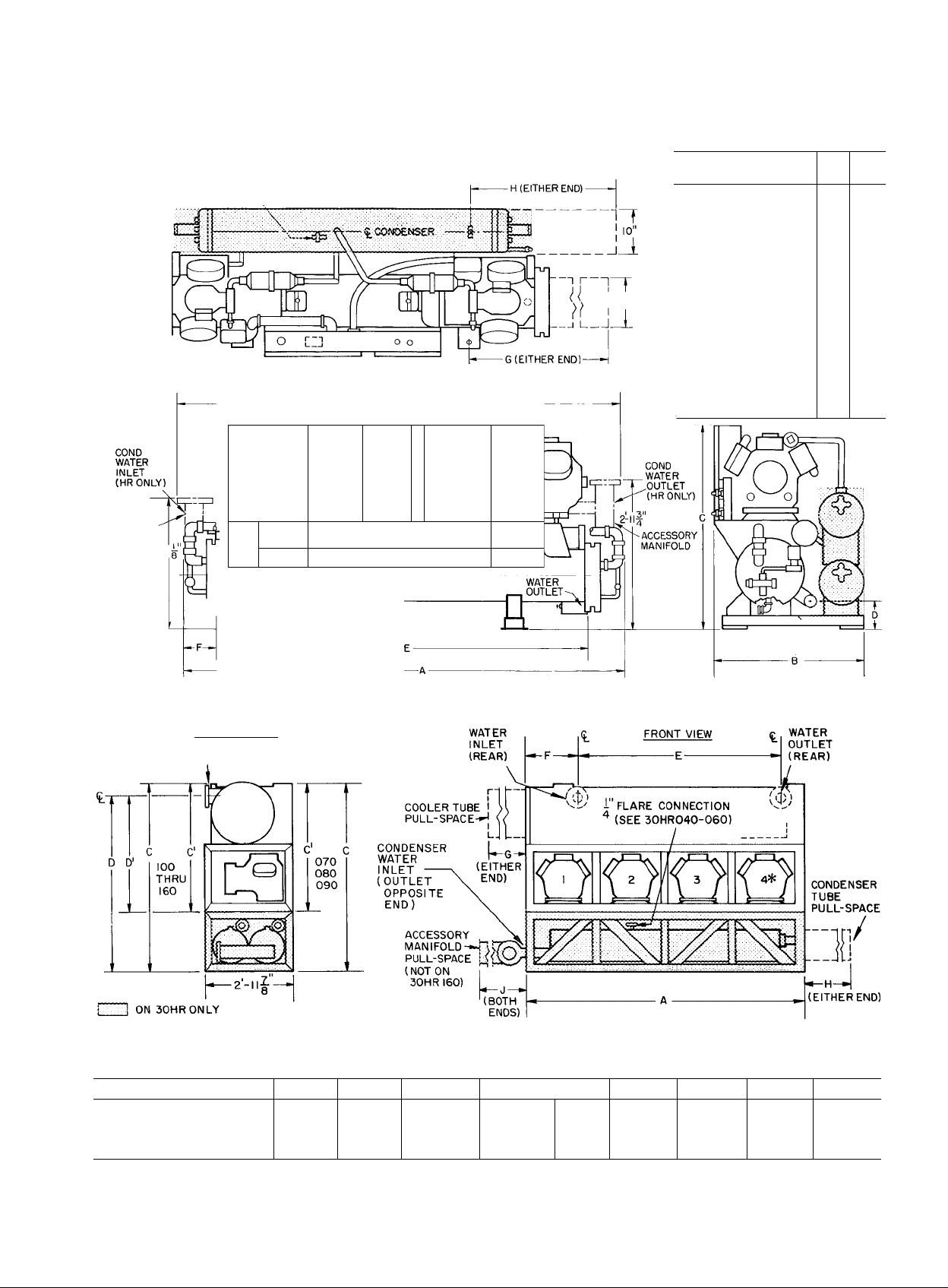
DIMENSIONS
30HR,HS040,050,060
ACCESSORYMANIFOLD
2-7
1" FLARE CONNECTION
FOR WATER REGULATING VALVE,
EACH CONDiSAMEON UNITS 30HR070-I60)
“I
_!
CONTROL
PANEL
D D
a
WATER
INLET
- i. COOLER
-9-0
3"_
0
0
0
”[
MTG HOLE
<L
n
V
! i-o|"diam
UNIT 30HR,HS
DIMENSIONS (ft-in.)
DIAM
Height to chilled
Distance between
chi 1 led water
outlets E
Distance from either
end of unit to
water outlet F
Pull Space
Cooler Tubes G
Condenser Tubes HI
Length A
Wiilth iuc? ^
" (HS) B
Height C
water outlets D
050,
040
060
7-6 9-0 */4
3-0
3-0
2-]%
2-1%
4-1%
4-1 %
0-6V s0-6 V4
6-2% 7-7
0-7%
0-8%
9-3%
7-0%
6-5%
6-5%
a
LEFT SIDE VIEW
WATER INLET AND OUTLET
NOTE: ALLOW 2-0 SERVICE SPACE AT REAR OF UNIT.
30HR,HS070thru 160
^SIZES 070-090 HAVE 3 COMPRESSORS; 100 THRU 160 HAVE 4.
DIMENSIONS (ft - in.)
1
UNIT 30HR,HS
070,080,090
100,110,120
140,160
*Overall length for 070 thru 120. Overall for 140,160 is 10-6-1/8, measured at cooler.
t30HR140 only (manifold not used on 30HR160).
A* C
; 8-6 6-3% 4-2% 5- 9%
i 9-4 6-5%
j
9-4 6-5 % 4-4%
C
4-4% 5-11%
D
5-11%6
D E F G H
3- 8% 6-1
3-10% 6-8
3-10%6
8-1
2-0%
1 -9% 7- 3%
0-7%
6- 1%
8-10%
J
7-4% 1-4
6-1
6-1 l-4%4t
1-4%4
Page 4

SELECTION PROCEDURE (With Example)
I Determine the unit size and operating conditions required to
meet the given capacity at the given conditions.
GIVEN;
Capacity ........................................................................................SOTons
Leaving Chilled Water Temp (LCWT)
Chilled Water Rise...............................................................................10 F
Entering Condenser Water Temp .....................................................85 F
Fouling Factor (Cooler and Condenser)
FOR 30HR (WATER-COOLED CONDENSER):
Enter the Ratings table marked 44 F Leaving Chilled Water
Temperature. Read down the left column (CAP ) to 80 tons
Note that either a 080 or 090 unit may be selected. Final unit
selection should be based on present and future job requirements
and the economics of the job. For this example, data from the
table is shown below for a 080 unit.
..............................................
............................................
PERFORMANCE DATA
44 F
0005
II Determine from Ratings table operating data for selected unit.
Unit...............................................................................................30HR080
Saturated Discharge Temp (SDT)
Compressor Motor Power input (KW)
Total Heat Rejection (THR) ....................................................101.5 Tons
Cooler Water Flow ..................................................................192.0 Gpm
Cooler Water Pressure Drop (PD)
Condenser Water Flow
Leaving Condenser Water Temp (Lwt)...........................................95.6 F
Condenser Water Pressure Drop (PD)
For fouling factors other than .0005 refer to the Correction For
Fouling Factors table to: adjust the required capacity, correct
the compressor power input, and correct the actual condenser
water quantity required. ForA t (SDT — entering cond water
temp) other than 30 F, refer to curve.
FOR 30HS (CONDENSERLESS):
Use the same method, with the exception that the condenser
water data do not apply. For the remote condenser data, refer to
appropriate Carrier condenser data publication.
...........................................................
.......................................................
..........................................
..................................................
...........................................
75.9 Kw
229.4 Gpm
107.0 F
10.7 Ft
12.0 Ft
CORRECTIONS FOR FOULING FACTORS
Ratings are based on .0005 fouling factor in the cooler and
condenser. Correction factors for other fouling factors are given in
the following table:
CORR FACTOR
FOULING
FOR CAPACITY
FACTOR AND COND WATER
Condenser
1 02
1.00
Clean
.0005
Cooler
1.01
1 00
.001 .98
.002
To correct capacity, adjust as follows:
a Adjusted required capacity (use to enter table)
_______
cooler factor x condenser factor
b. Actual compressor power input
= compressor kw (from table) x correction factor for
power input
c. Actual condenser water quantity
= gpm (from table) x cooler factor x condenser factor
-
required capacity
.94
________
CORR FACTOR
FOR
POWER INPUT
Condenser
98
1.00
1 03
1.10
Ratings based on: 10 F chilled water rise (suitable for 5 F to
15 F rise without adjustment), .0005 fouling factor in cooler (and
condenser on model 30HR), 15 F subcooling, and R-22.
Ratings in boldface type (44 F chilled water page) are in
accordance with the latest ARI Standard 590. Conditions:
30HR — 44 F leaving chilled water temperature with 10 F rise,
95 F leaving condenser water temp with 10 F rise and .0005 fouling
factor in cooler and condenser.
30HS — 44 F leaving chilled water temperature with 10 F rise,
.0005 fouling factor in cooler, 105 F condensing temperature for
remote water-cooled or evaporative condenser, 120 F condensing
temperature for air-cooled condenser.
Ratings based on 15 F subcooling. On 30HR units this occurs at
30 F A t (SDT — entering condenser water temperature.) When a
30HR (water-cooled condenser) unit is selected at conditions other
than 30 F A t use the curve below to correct the ratings table
capacity.
RATINGS
The following ratings tables are for both 30HR (water-cooled
condenser) and 30HS (condenserless) models. Condenser water data
apply to model 30HR only. Ratings beyond limits shown and/or
brine ratings are available in Carrier Application Data publications.
Ratings shown for Saturated Discharge Temperature (SDT) over
120 F do not apply to model 30HR.
Correction = Ratings table capacity x percent capacity correction
(from above curve).
Above 30 F At add the correction to rating table capacity.
Below 30 F At subtract the correction from rating table capacity.
30HS units matched with remote condensers which have greater
than (less than) the 15 F subcooling in the ratings, increases
(decreases) system capacity. To adjust capacity, multiply capacity
ratings by 0,94, then adjust this result upward by 0 4 percent for
each degree F of available subcooling
Page 5
PERFORMANCE DATA
30HR,HS RATINGS
Leaving Chilled
Water Temperature
42 F
COOLER
FLOW DATA
lOF RISE
(tons) (F)
34 0 j 131 4
36.G : ! 24 C
38 G
. ..“'V'.v,,
■ 40,7 Î
42 C i
44 C i 94 6 41 2
38 CÎ
40 0 j 127 4 52 6
4? C 1
.:.42.2. 0:12Q,0:: .50.2
46.0
46.4
46.9 1 5.05.0 .45.5. ...59.8
48 0
50 0
44.0
46 C
48.0
.:::49.7. i.:î2Û.O .l.S9:6T..66,.6.; .:U9.2
50.C
52 C
54,0
...55.3:
56.0
. ..56.3. Î ’.Q5.Q
58 C
60 0 96.8
62 0 92 2 50 4
54 0
56.C
58 C 126 2 74 0
60 0
.....6L2
62 C ^
64.0
66.0
68.0
68..5
. ,69.3.
70 C
72 0 100 2
60 C
62 C 132.3 86 8 86 6
64 0
66 C
68.0 121 8
, 69.0,
70. C
72 C
74.0
76.0
V 77.5
78.0
.78.,!,
80. G
82,0
65 0
70 0
75 C 122.2
: 76 .4, i: J2S.0 .90,5
80 0
85 C
S6.0
, ,:S6.3.
90.0
95 0
! .120.0 . 49..G .50.9Î .89.0. 7.4
I 1 16 7 48 0
109 4 45.7
040
107.0 44.9 53.4
- J05.0..
102 1
134 2
120.8
Ì08 n
050
ÎÔ6.8 46.2
101 6 44 6 60 7 115.2 5 3
95 1
133 9 64 4 ^62 3 105 6
128 9 62 7 63.8
124 ]
i 1 19 4 59 4
1 14 8
060
.1..1.C..3..
U07..4 ..5.5.4.
1C5.S.
101 3
134 2 77 4
130 2 75 7
122,4
; 120.0
118 6 70 8 82 1 148 8
070 114 9
111.2 67 7 85 2 158 4 7 3
107.6
; 306.6 :
;..ÌQ5.0,:
103 9
136 0
128 7
125 2
! 123.0 80.9 92 C
i ¡8 4 80,1
080 115 0
111 7
108.5 75.5
.Ì06..1..
105.2
, 5.05.0
101 9 72 5 100 6
98,6 71.0
138 6
130 1
114 5
090
107.0
Ì05.5
,5.05.0.
99 5
91 8 75 9 1 16 5
(tons)
48 8
52 2
.50.2 .50.2 86 4
51 6 91.2 7 8
53.0
.53 ..8 .. 98-9 .. 9.2 78.5 91 4
44.3.
43 4
54.3
55.7 105.6
54 8 53 6 91 2 3 3
54 9 96 0
SO s
56 3 100.8
,55.4 ; 1GÎ.4 4, ;
46 F
42.7
61 0 65.3
57 8
-jr\ rv
..56...3,
. .«’.y V.
.7Î..C. .132.6
.,71.6.
..54.S.
.54.5 ..7.LS.
53 3 73 1
51 9
72,4
80..5
.7,1.3
.81.5.
69.2 83 7 153 6 6 9 1 15 5 92 4 2 6
66.2 86 8
6.5.8
.0,5.2.
64 8
63 3
88 6
85 0
83 4 89 7
81 7 91.2 163 2
78 5
77 C
.-74.4, 93.6
74.0
:..99.ü
.73.9
102.2 196.8 11.3 [202.1 87 1 9 5 329 2 87 4 23 7
100 2 93 5
95 6
91 4
,100.9
104 '8
87 3
83.4 ,108.7 204,0 1 ? 1 151.0 92 6 4 5
82.7 Î09.S
:82..4
l'D9.7 ,207.2 .32,5. 151.1
1 12 6
79.6
Gpm
81 61 6 3
100.8 9.6
1 10 4 4.9
5v.2
59.5 !!f.2
'll 2.6 5.0
62 1 120,0
1 10.4 4 9
1 15.2
120 0
66 9
124 8 6 2
68 4
: 79.6 6 7
,,!.3.4..4.
,135,2.
139 2 7 8
144 0 8 3
74 7
148 8
76 3
129 6 4 9
76 C
77 5
134 4 5 3
79 0 139 2 5 6
3 A_A r\
. i:47_o . .6-2 1 15.5 92 0 2 5 1 15 5
163.2 7.S
n64',5
.87.2
87.9; :.:166.5. 8.0
88,4 168.0
172 8 8 7
90.0
144 0 6 0
85 2
148 8 6 4
88.2 153 6
158.4 7 3
„:T65;6 .8.0.
Î 68.0 8 2
92 S
94 3 172 8
95.9 177 6
97.4
182 4
: TS5.9: lO.'.l
187 2
99 G
137.4 .10.2
192.0 10.7
156 0
97.2 168 0 8 2
180.0
:l.83..3i 9.7 151 0 91 5 4 5 151 0 96 5
Î02.0
192 0
2'D6.4
216 0 13 6
228.0 15 1
75 80
PD
Gpm Lwt (F) PD
-
_ _
7 0
72 0
96 0
97.6 .9.0 73 3 92 5 2 2
:..7.0;.
....7,2.
72 0 92 2 2 1
8 7 72 0 92 7 2 1 78 4
90 4 89 4 3 2
10 5
174.3 82 7 11 1
3 7
4.1
78 0
78 0 93 1 2.1 90 6
5.0 78 2
83 4 92 1 2 3 1116
102 1
5.8
183 3
4 5
S 7
. S.7. , 84 0
5 8
84 0 94.1
84 0 94 6 2 1 84 0
84 0 95 0 2.1
87 1 94 6 2 3 1 15 6 94 7
95 9 92 9
7,3
101 2
131 8 88 3 5 4 201 3
200 1 84.0
8 9
6.0
6 4
115 5 92 1 2 6 115 5 97 1 2 6
1 15 5
1 15 5 93 1 2 6
7.9 1 15 5 93 2 2 6 142 2 94 8
120 1 92 6
8 2
127 2
163 6 88 2 5 0 256 3 88 5 11 5
6.9
7 8
127 5 92 3 4 0
127 5 92 5
8.7
127 5 92 8
9 2
127 5
9,7
127.5 93 4
127 5 93 6 4.0 158 8 94 9
iC 2
128 1
129.4
155 5
7 1
9 4
10.7
151 0 92 0
Î2.4
151 0 92,7
200 2 88.8
92.0 2.1 72 0 97.0
__ _
_ _ _ _
_
92.2
93 2
89 2
83.1 11,2
_ _
-
_
_ _
_
94 0 2.1
92 1 3 1
~ - - - - - - - - _ _
_
— _
_ — —
— _ —
—
92 8 2 6 1 15 5
91 7
_ _ _
— — —
— _ —
_ _
—
— _
93.1 4.0
93 5 4 0 169 9
93 3
90.5
_ _ _
_
— — _ - —
— —
92 7 4 5 185 5 94 4 6 7
_
2 4
_
2.1 78 0
2 1
3.6 151 2
_
_ _
2 1 84 0 99 1
2 8 I3I 6
12 6
_
2 7
3 : 175 7 92 1 5 7 288 1 92.4 14 4
—
4 0 127 5
4.0
4 0
4 0 172 8 93 8 7 0
5 8 227 5
_
4 5
4 5 178.1 95 0
7 7 316 7 88,8 17 9
-
CONJJENSER WATER
Entering Water Temperature (F)
85 90
Gpm
Lwt(F) PD
_ _ _
-
_ _
72.0
97 2
96 2
89 3
103 2
129 2
141 6
115 5
133.2
160 7
127.5 97 3
127 5 97 8 4.0
127 5
135.1 97.3 4.5
151 0 97.0 4.5
160 7
94 3 3,1
92 6 4 1 162 0 93 2 9 9
90 1
- - - - - - - -
_
_
_
_ _ _ __ __
97 2 2 1
95 6
97 3 94 6
92.8
89.6 7 7
- - - - - - -
_
_
__ _
—
84 0
99,0
95 1 97 7 2 8 131.2 97 8
99 6 2 1
93 1
92 3 6 3
88 7
_
_
_ _ _ _ _
_ _
_ _
— _ — — _ —
97 0
97 4
97 8 2,6
95.7 3.4
93 2 4 8 253 0 93 4 11 4
_
_
_ _
_
_
—
_
97 5 4 0
98 1
94 0 6 8
90 6 11 8
_
— —
96 4 5.2 230.0 96.6 10.0
-
- -
Gpm
Lwt (F) PD
_ _ _ _
_
72 0
2.1
72.0
2.1
2.5 103.5
i:28.T
227 3
6 3
78 0
IT? 9
2.8
3 3
]42„3 .95.0 Ó.8.:
4.2 174 2
__
_ _ _
84 0
2 1
84 0 104 1
2 1
94.2
4 1
5.7£),:6 .9.T
5 4 203 0
224 6
12 7
_ _ _ _
_ —
_ — _ _ — _
2 5 115 5
115 5
115 5
2 6
140 3 99 6
190.3 ^6 0
3 8 SiÓ.2
__
_ — _ — —
_ _ _
_
_ — —
4.0 127 5
127 5
127.5
145.5
4.0
1.88
6.0 Ì236.3 . : .95:,C.:.
260 7 94.1 IS 3
267.3 93.9
_
_
4.5 151 C 101 5
151 0
6.2 '263.:7
286.0
_
102 0
102 2 2 ;
97.3
;95.;,Q’
90 7 18 0
_ _
_ _
102 2 2 1 80,7 106.7 2 2
96.1 5.6
93 2 10 2
—
_ _ _
— _ __ _
104 0 2.1
102 4 2.7 130 6 102 6
9 3 .5
92 8 16 2
_
102 0 2 5 1 15 8
102 1
102 4
. 95 0
- - - - - -
_ _ _
_ _ — — —
102.3
102 5
102 8
100.8 5 1 211 2
97.4
—
-
- - - - -
_
—
-
— —
__
— — -
102 0
T::'95.1QV: T3;3.
94.5 15.C
-
-
-
Gpm
Lwt(F)
_ _ _ _
74 2 106 5
2 1
87 2 104.3
4,1
164.4 97 8 9 9
; 6.'2
215 7
_
—
— —
_ _
_ _
_
_ _
_
_
96 6 15 5
_
_ _
90 6
2 1 93.0 107 3
204 6 98 2 13.2
5,3
13,0
_
_
2 6
2 6
208 1 99 9
3 7
6.6 328 9
7.9
_ _
4 0
4.0 128 2
4.0 158 2
305.0 97 7 20 6
8 3
:52.7,
16.0
_
4.5
4 5 177 3 104.3
— -
-
107 7
—
— — _
—
—
_ _
—
_
— _
—
_
106.9
1 17 0 106 9
148 5 103.6
96 4
_
— __
—
—
_
_
_ _
-
— —
-
-
- -
—
_
-
-
-
107 3
104 3
100 9
- -
- —
- -
— —
- —
—
106 5 4 5
- _
-
- —
127 5 107 3
151.0
-
PD
2 2
3,0
_
_
_
_
_
_
_
2 4
2 6
5 3
_
_
_
_
_
2 5
2 6
4.1
7 8
18 4
_
—
—
_
_
4.0
4 0
6 0
10.3
—
—
6.2
—
CAP. — Capacity
KW — Compressor Motor Power Input at Rated Voltage
r ~1 Shaded areas show ratings for 105 F and 1 20 F condensing temp and ratings with 95 F leaving condenser water temp with 10 F rise
* Ratings for SDT above 120 F do not apply to 30H R
Lwt — Leaving Water Temp (F)
PD — Pressure Drop (ft)
SDT - Saturated Discharge Temp (F)
THR — Total Fleat Rejection (tons)
Page 6

^2 P Leaving Chilled
Water Temperature
CAP.
SIZE
SDT*
(tons)
75.0
80 0
85.C
87.6 '
90 0
95.0
98.7
99.5
100 .0
105.0
85 C 1
90 0 1
95.0
.95,5:
100 0
105.0
107:71
iOS,2.
1 10 c
1 15.0
90.0
95.0
100 .0
■f03;3
105 0
1 10 C
1 15.0
116.6
)57.0
Ì20.C
125 0
102 .0 Ì34.5
106 0
1 10. 0
1 14.0
1)5.7
1 18.0
122. 0
126.0
129.0
.13G..5,
134 0
1 17.0
121.0
125.0
129.0
.;3U
135 0
139.0
;45;0
546,4
1 50 0
154 0
(F)
137.4 112 4
130.3 108.0 1 10.7
1 23.6
;t2o;q' 501.8: .Ì5Ó.6
117 0 100 1
inn
1 10.7 96.4
l'Oó.Oi
:5.Q5.,0.
104.4 92.8 126.3 240.0 11 3 166.1
98 :
133 ;
126.8 115 8
120 6
!.12a.O:' i 11.415:27.5::
114 7
1 in
' ' 108.8 n04 2
105.7 ¡102.3
505.0
103 0 10 0 6
97 1
135 6 132.1 127.5
129 6
123.8 123 6 135 1 240.0 11.3
1 T20.0?120.'9.
1 1 18 2 119 7 139.0 252 0
520
1 12 7 1 15 8 142.9 264 0 13 6 158 0
' 107.2 11 2. 1 146.8
105.5
505.0
101 8 108 4 150.8
96 3
130 1 151 4 149 0 254 0 7.0
125.8 148 5 152 1
121 7
1120 .0
140
Ì ‘¡7.5
113 5
' 109.4
106.4
5,05.0
101.4 127 3
134 : 179 6 feo 0 28Î.C 8 4
130 1
126 C 172.8 174 1 300.0
122 Q 169.0 177.C 310 .0
; 120.0,
160
1 16 1 162.91181 3
1 12 2
106.3 1,52.3
1Q5..0
101.4
97.51143 1 194.6 370.0 13 7
PERFORMANCE DATA
-‘■"T ' "
j COOL
,ER
THR
KW
(tons)j Gpm
106 9 180 0
1 14 5
104.0
1 18.4
] 90 4
935/
T2S.3 236.9
93.5:1.125.9 238.S
89.2 130.3
119.1 204 0
120 .0
122.9 216.0 9.1
111.8
126.8 228.0 10. 2
108.0 130.7 240.0 Ì Ì 3 145.0
134.6
5 3c. 7
,505.8 137.2
138 6 264.0 13 6 194 2 92 2 5.1
97 C 142 5 276 0 14.9 312 5 86 0
127 8
131.3
,137.6
14S:T
no. 9
148.4
5 50.6
104.8 154.8
154.6 145 9 245.0
144.7
155 1
'¡43:3'
156.3
Ì 4 2
158.1 283'C ‘
137 7 161 1 293.0
164.1
134. 2
566.4
5.3 5.6
167.5 353-0 ;0.2
130.3
170 2
DATA
LISE
PD
Gpm
Lwt(F)
_ _ _ _ _
6 3
192.0 7 2
204.0 8.1
,8.6. 126 0 97.2
210,4.
216.0
228.0 10. 2 126 0 98.3
n.G 151.1 94 9
n.i. 160.1 93.9
252.0 12.4
_
— _ _ _ _
9.1
126.0
268.6 86 .6 10.7 - - - ~
8.1
_ _ _ _
_
229.2. .50:3..
252.0
258.5 53.1
259.6
216.0 9 1
228 0 10 .2
:24S„0.:
2.76.0
279:.B 55 3 177.2
280.6
288.0 16 2 222 8
300 0
264 0
274.0
278.0 8 .2
302.0
3I0V0
322.0 10.7
145 0 96 1 2 9
145.0
12 4
164.9
171 3 94 3 4 0
13.1
_
— — _ _
—
158.0
12.0
12 4 158 0 96 1 2 7
14 9
162 3
15.4 181 5 94 6
17 6 355.5 85 4 12 6
■‘8.5 160 0 99.0 2.9
10.0
_
6 5
_
—
7 5
_
8.0
160 C
9.0 160.0 99.0 2 9
169 0
9.6
197 0 95 0
215 0 94 0
275 0 90.0
_ _ _ _
176 4 171 1 290.0 8 9
10.G
.566.9 578,5.1 3.15.0. T0.3
158 71184.1
150,8 189.3
147 1
324 0
334 0
188-3 34S.0 12.3
351.,0:
191 8
360.0 13 1 308 0 90 0 6 7
10 8 180 0 99 0
11 4
12.5
_ — — _ _ _
-,
9.4
_
180 0 99 0
180 0
225 C 95 0
100 0
244. C
429 0
30HR,HS RATINGS
ENSER WA
COND
8 0
102 .2
102 6
94 9
93 9
93 2
101. 1
98.3
95.0
94.3
92.1
100.9
101.7
96.9
95 1
104.0
98.0
95.0
94 0
104 0
104.0
95.0
90 0
ater Temper
PD ; Gpm
_
2 6 126 0
132 9
2.6
197.8
3.5
6.2 300.9-
335.2
7 2
358 5
7.9
_
145.0
2.9
162 5
2 9
245.1 98 2
4.3
6 4
33.1.0 ,:9S.O. .
7 Ì ¡356 4
9 8
-
_
_
158.0
2.7
158.0
2 7
2 7 194 9
4 6 298,5.
5 8 I35.5-.6
372 9 94 6
6.2
10 6
- - - - - - -
_ _
_
_ — —
160.0
2.9
2.9 174 0
219.0
3 3
4.9
298 0 98.0
7 21400.0
8.9 474 0 94.0
16 3
_
181.0 109.0
2 3
215.0
2 3
274,0
3 1
6.4
447 .0
517 C 94 0
7 9
14.6
E
itering W
7 5
_
97.6 2 6
93 3 4 3
_
-
Gpm
_
2.6
126.0
126 0
2.6
148.1 99 8
3 6
201.7
4.C
218.1
229 2
_
Lwt(F)
__ _ _
145.0
96.8
97 4 2 9
95 0 3 8
_ _
—
95 9 2 7
96 7 2 7
96 7
95.1 3 4
91 2
_
—
_ _ _
98 0
98.0
— _
__ _ _
94.0
86 0 12 ^
2.9
12.4
_
2.9
3.5
5 2
_
_
2 9
3.3
4.3
5.C
7 7
2 3
2.3
2 3
3.6
4.2
145 0 101 8
177.3
220 .0
231.8
275 7
158 0
158 0 1 01 .1
158 0
208.2
235 7
243 8 94 6
325.1 91 1
160.0 103 0
160 0
172 0 103 0
214.0
264 0
298.0
419 0 90 0
180.0
180 0
209 0 101 0
301 c
335 0 94 0
458.0
TER
ature (F'
"^Ts
Lwt (?) pd" Gpm
_ _
_ _
_
107 2
106.4 2.9
99.8
:, 951.0 . , M3.2
94.1
93.5 18 3
_
_
_ _
_
_ _
106.1
104 3 3 7
94.3 15.9
— — — _ _
_
_ _
2 6 142 9
172.0
6.0 296.3 99.9 12 .8
16 2
_
2.9 154.0 109 8
218.7
7.9
389,8
1:3.,8
- -
__
_
— — _ _ _
__
— _ _ _
105 9
106.1
102 .6 4.1 274.2 102 5 7 7
.. 96.8,.
.55.0 12 .6
_ - _
_
—
_ —
108.0 2.9
107.0
103.0
,..95.0. :15*Q.
__
164 8
2 7
182 2
2.7
503 1
..9.0,
13 7
_
_ __
_ _ _
_
194.0 109.0 4 1
3.4
225 0 107 0 5 4
312.0 102.0 9 7
5.2
8.9
480 0 98 0 20 7
20 3
90^ -
Lwt (F)'
_
_ _
109 6
106.5 4 6
_
_
_
_ _
_
_ _
_
_
_
_
104 4
98 4 18.8
— _
_
— _
--
- -
__
_ _
110. 1
108.3 3.6
24 1
97 0
_
_
_ _
_
_
_ _
_
_
_
—
_
_ _ —
- - - - - -
_
...95.0
-
_
—
—
105.0 3 3
101.0 5.3
— — _
-
_ _
_ _ _
_ _ _
223.0 109.0
2.3
286.0
396 0 101.0 11.0
13.9
18 7
_
_
— —
_
_ _
105.0 5.8
—
_ —
- - - -
PD
3.2
3 3
6 4
2 9
3.5
_
_
__
_
_
_
_
_
_
_
_
„
_
_
—
_
—
44 F
CAP. ¡SIZE
(tons)
5
36 0 :
38.0 i
40.C
040
42.0
42.6
44.0
46.0
Leaving Chilled
Water Temperature
SDT’
(F)
128 9
121.7!
Î2C*Q.^
114.6:
107.Sr
105.0;
100 3
92.9
THR
KW
(tons)
52.4 50.9
50.2 52.3
49.6; 52.61
48.01 53 6 I
45.7; 55.0 [
44.9; 55.41
43.4' 56 3 !
41.21 57.71
COOLER
FLOW DATA
lOF RISE
G pm
PD
86.4
7 0
91 2
7.8
92^3 ) 7.9
96.0 I 8.7
Î00.3 1 9,6
Ì02.4 i 9.8
105 6 no.5
110.4J11.5 Ì218.0
Gpm
72.0
72.0
73 7
81.6
107.0
75
Lwt (F)| po’
92.5
92.9
92 9
91.3
87.6
¡16 7
81 4
Gpm
2 C : 72.0
2 1 i 72.0
2 2 90 3
2.6
108.3
4 4
165.4 I
CONDENSER WATER
Entering Water Temperature (F)
80 _
PD
2.0
2 1
3 2
4 5
10 0
Gpm85Lwt(F)
72 0
102.5 2 0
79 3
m.7i
171 4
95.0 6.2
93.0 I 10.8
Lwt [F)
97.5
97 9
94 6
92 4
88 2
PD
2 5
Gpm
77 6
105.3
217.0
90
Lwt(F)
106 3
102 3
96 1
PD
2.4
4.3
16.7
Page 7

PERFORMANCE DATA
30HR,HS RATINGS
Leaving Chilled
Water Temperature
44 F
CAP.
(tons)
40 G
42 C
44,0
44.4
46
48 C
42,5 n07.2
49.2 Î05.0
50 0
52 C 96 2 43 7
46 G
48 C
SO 0
51.9
52 C i
54 C
56 C
57.4 307.8 56.3 73.40 T37.S
58.0 106 5
5S.6 305.O1 ' 55 .3
60 c
62 C
64 C
56 C
58 C
60 0
62. C
63.8
64 C
66 0
68 C 112,6
70,0
n.z
77.C
72.2
74.0
76 C
62 C
64 C 133 6
66 c 130.1
68 C 126 6
70 C
72.0 320.0 82.3
74 0 1 16 7
76 C
78 C
80.0
80.4
83.2 305.0
82 0 103 8
84 C 100 6
86 C .97 3 71 4 106 3 206 4
70 C 135 0
7^ 0
79.6
80 C
85,C
89.2
89.7
90 0 104 6
95 C 97 2
SDT*
SIZE
T20.0, .5303.
050
T20.0
060 1 10 9
070
080
090
KW THR
(F)
134 4
56 :
127 8
53 8 57 3
12! .4
51 6 58 7 105.6 4.5
Ì Ì5 :
49 6 6Ü i Ì iO 4
108.8 47 .6 61.5
47.3
.4.6.8 62.3
102 5
45 6 63 0
133 9 65 6 64 6
129 0
63.8
62.1
124.3
60,5 69,3 124.5
Ì19 8
60 5
58 9
115 3
57 4
5^ 8
i02 1
54 3
97 6 52 8 77 C
51 4 78 6
93 2
135 1
79 2
77 4 80 0
131 1
127 3 75 7 81 5
3 90 c;
74.0
320.0
72.4
1 19 8 72 4
70 8
116.2
69 3 87 7
67.7 89.2 168 0
109.C
306.9 66.9
105 4
ÓÓ.3
305.0 66.3
101 8 64 8
98 2
63 3
137 21 90 8 87 8 148 8 6 4
89 C 89 3 153 6
87 2 90 8 158 4
85 4 92 3 163 2
123,3 83,8 93 8 168.0
80 5 96 9 177 6
1 13 4
78 9
1 10 2 77 4 100 0 187 2
107 0
75,9
306.4
75.61303.9
74.91 102.5
74 3 103 ' 196 8
72 S
100 0 98 4 168
1.27.0 95.5 1Q2 ^ 180.0
320.0Ì 93.6 30S.6
119 4 9i 3 105 9
87 3
112 0
83.9
305.7
305.0 83.5
83 4 1 13 7 216 G 13 6 151 3
79 5
FLOW
lOF
(tons)
101.5 1 9? 0
Gpm
55 9 96 0
100 8 4 1
59.0
3Q6.6:
1 1 5 ?
336.4 5.4
63;9
.338.3. S.S
¡20 0
124 8
64 4
1 10 4
115 2 5 3
66 1
^7 6
120.0
124 8
69 2
129 6
70 7
134 4
72.3
139,2
73 9
74.3] 340.3 7,9 107 4 91 7
144 0
75 4
148 8 8 9 195 9
153 6 9 4
134 4 5 3
78 5
139 2
144 0
148 8
83.0
353.3] 6.8
84.5
84 6 153 6 6 9 115 5 92 6 2 6 115 5
158 4
86 1
163 2 7 8 115 5 93 3 2 6 1 15.5
370.8 8.5 115 5 93 8 2 6 146 7
90.3
90.8
172 8
373.3 8.7 125.7
90.9
92 4 177 6 9 2 153 6
182 4 9 7
94 C
95.3 372.8
98 4 182 4
392.9
395.0
104 7 201 6
393.0
192.0
204 0
109,8
133.1 234.2 T3.3 151.0
133.4
235.3
1 17 6 228 0
COOLER
DATA
RISE
PD
3 7
'.■;4.5'.
4 9
5.3
5 8 101 9
6 2 175 6 83 8
4.9
5.8
6.3
Ô 2 84 0
6 7 84 0 95 2
7 ?
V..7.6
7 8
8 3 132 0 88 7 5 4 198 6
5 6
6 C
6 ^
7.3
8 ?
87 122 8
6 9
7 3
7 8
8,2
8.7 127,5
9 2 127 5
9 7
10 2 127 5
10 7 127 5 94 1
30.8 127.5 94 2
U.O 134 5
1 1 3 144 4 92 1
1 1 8 181 7 88 8
12.4
8.2
9 4
30.6
10 7
12,1 151 0 92 8
33.4 151 5
15 1 260 6 86 2
CONDENSER WATER
Tiering Vl
7 5 ”
Lwt(F)
Gpm
_
_ _
_ _
78 0 93 0
78 0
78 0 93 8
79 2
88 4
84 0 94 7
84 0 95 7
90 1
97 3 93 2
115 5
115 5 93 0
115 5 93 6
208 6
127 5 93 5
242.3 85.5^
151 0
151 0 92 1
93.4
93 7 2.2 101 2
91 8
_
—
- - - _ _
_
—
—
_
_ _
— — _ _ _ _ _
93 0
_ —
_ _ _ _ _ _ _ _ _ _
PDEGpm
.
89 7
—
— _ _ — — —
-
94 8
94.5
84 4
-
— _
92 5 2 6
92 8
92 4
89,5 4.4 230 0
85 8
_
_
_
93 2 4 0
93 8
93 3 4 4
_ _
_ _ _ _
_
2 1
2 1 78 0
2 ;
2 7 120 7 92 4
148 2
3 6
10 3
— —
— _ — — — — — -
2 1
2 1
2 1 84 0
2 1
2 5 119 8
2 9 132 6
3 5 151 4
12 0
_
- — -
- —
115 5 97 5
1 15 5 98 0
2 6
128 5 96 7
2 6
164 5 93 3
2 9
170 6 92 9
3 G
357 5 86 3 21 e
7 8
_
__
_
_
4.0 127 5
127 5
4 C
127 5 98 5
128 7
4 C
4 0 156 8 95 5
4 0
164 2 94 9
183 3 93 4
5 1 202 5
7 7 279 0 89 0
13.3
_
92 0
93.3 4,5 184 4 94 9
93 2 4 5
93 2 4 6
151 0
4.5
4.5
151 0 97 1 4 5 151 0
4 5 151 0 97 8
195 0 94 2
201 1 93 8
12 5
8 0
Lwt (F)
_ _ _
_
78 0 98 0
91.5 96 0
84 0 99.7
84,0
97 1 97 9 2,9 133.3 98.0 5 5 205.6
98 4
94.6
90 1
- - - - - - -
99 8
100.2 2 .1 96 7
94 7
93 4 5,4 202 0 93 8 12.8
91 9
89 1
—
-
_ __
- -
_ - - —
97.6
98 3
94 8 4 C .'2T7.21 9S.0.
89 7
_ _
_
_
_
_
98 0
98 2
98 6
92 2 9 5
- -
_ _ _ _
____
97 0 4 5 151 0
- -
emperature (F
ater
"T „ 1 ^ ^
PD
Gpm 1 Lwt (F)
_
21 78 0
21 83 2 102.3
2 9 127.7 96.5 5.5
3.5 148. Î
185 0 93.1
5.0
7 4
—
21
2.1
4 4 57615
241.6
71
12 4
- —
— -
-
115 5
2 6
115 5 102.6 2 6
2 6
115 5 103 0 2 6 143 0
2 6
2.61135 2 100 6
177.8
3 1
257 1 93 5 11 6
5.C
271 5 93 1 12 9
5 3
9 4
4 0 127 5 103 0
4.0 127 5 103 2
4 c 137 3 102 2
4 ; 172 3 98 9
229 4
5 9
6 4 ^244.7 95.0
285 9 93 6
7 9
328 5 92 5
17 3
103.0
—
_
84 0
104.7 2.1
84 0 104.8
102 6
-
-
-
102 5
-
_
____
PD Gpm90Lwt(F)
_ _
_ _
_
2, 1 83 7
2 4 1116
95.0
—
95.0
92.5 18 7
- - - - -
— -
— -
95.6
7.4
■| Ì .9
_
- -
-
- -
97 1
- -
_
- -
- —
_
2.1
2 9 133 7
9.7
- - —
_ —
_
2 6
3 5
5.8
8.4
4 0 127 5 108 0 4 0
4 C 148 4 105 6 5 3
4 6
7.0
12.0
53.6
13 2
23 6
- - _ - - _ - -
102.0
4 5
163 1 101.3
278.9 95.0
6 6
7 3 303 2 94.3 16 6
7 8 317 2
102 1
93.9
-
14.2
18 C
- -
4 5 151 0
4.5
5.3
-
- -
-
- -
- -
-
-
_
97.4
-
_
_
13.3
14 7
...
10.4
PD
2 4
4.3
2 7
2.6
6.8
4.5
_
__
_
_ __
106,8
210 1 97.0 14,7
291.7
264 7 99 1 15 7
102 9
_ _
— —
— —
-
95,0 107 5
96 1 107.3 2.8
102 7 5.5
98.4
-
—
-
- - -
_
115 5
115 5 107 6 2.6
193 9
191 7 102 3 8 6
107,5
104.5 3.8
100 9
- — -
—
- - -
— — -
-
_ _ _
„ _
_ _ _
_
_ _ _
107.0 4 5
151.0 107 1
234 2
101 5
_
_
_
_ _ _
- -
_
—
—
-
-
-
-
-
-
-
-
-
—
-
_
_
_
_
_
-
CAP. — Capacity
KW — Compressor Motor Power Input at Rated Voltage
Lwt — Leaving Water Temp (F)
Shaded areas show ratings for 105 F and 120 F condensing temp and ratings with 95 F leaving condenser water temp with 10 F rise
•Ratings for SDT above 120 F do not apply to 30FIR
Boldface values in shaded areas are ARI rating points: standard 590
PD — Pressure Drop (ft)
SDT — Saturated Discharge Temp (F)
THR — Total Fteat Rejection (tons)
Page 8

P Leaving Chilled
Water Temperature
PERFORMANCE DATA
30HR,HS RATINGS
. - -
CAP.
(tons)
100 0 109 4
ÎÔ2.6
103.5 105.0
105 C
1 lO.C
100 c
105 0
1 10.C 108 1 105 2
111,8 106.0 103.9
112.6
1 15 C 102 3 101 6
Ì 10 C 120
125 C
140.C
size! SDT*
80.6
85 G
90. C
9Ì.5
95 C
100
85 C 138 1
90 C
95.0
99.6 120.0
no 113 8
120 0
95 0 134 5
100 0 128 6 129 3 136 7
105 0
t07.7 120.0
115 0
120.0
121.0
121.8 105.0
130 0
107 0
Ilio
115 0 125 6
'^9 0
120.6
i 23 0
140
127.0
.0 109
134.0
135.9
139.0
143 0
121 0 135 0
125 0
129 0
133 0
136.4
160
144 0
148.0
151.0
152.2 105.0
156 0 101 4 149 3
160 0
KW
THR
(F) (tons)
135 2
113 0 1 12 1
128 4 108 7 1 15 9
104,7
121 9
120.0
115 6 100 8 123 6 228 d
106.3 95.2 129.6 246.1 11.8 156 3 94 9 3 9 208 9
103 3 93 4
97.1 89 8 135.5 264.0
131 6 121.1 124.4 216 0 9 1
125 5
119.6 112 9 132 1
105.0
96 6
123.0 125.1 140 5 252 0
117 6 Ì2Ì 1 Ì44 4
1 12 2 117 2 148 3
106 9 113 4 152 2
105.S 112.7
lOl 6 109 7
96.2
134.0 157.2 151 7 257 0
129.81 154 0 154 7
121 6
120.0 145.7
117 6 143.7 163.8 295 0 9 2
113 6 140 1
106.8; 134.0
105.0 132.3 173.5; 326.0
101 9 129 7 175 8 334 0
98 0 126.3 178,9 343 0
131 0 180 6
127 1 177 0 179 3 310 0 10 C
123.2
120.0; 169.S
116 5
112 7 161.9
108 9
106.1
97 6 145.4
1 19.7
103.4 120.4
97 C 127 6
94.3 130.3 248.5
131 5 252 0
125 6 120 7
116 9
128 2 228.0 10.2
113.1 131.8
109.0 136 C
139.9
141.3
103.2 142.0
143 8
97 9
147 8
133 7
133 Ò
122.9
142.6
153.0 290.4 16.5 182 4 95 1 3 6 242 9
153.6 292.3
112.1
Ì 56 2
160 ’
106 1
150 6 157 3 276 0 8 ;
147 2
160.8 286 0 8.6
162.0
166 8
169 8
136 6
172.0 322.0
183 8 173 2
176 3
173. 2
182 2
1S4.6 327.0
166 1 187 2 336 0
190 C
157 7
192 8
194.9
154.5
153.2 195.7
198 4
201 3 384.0
COOLER
FLOW DATA
lOF F
?ISE
p b ’
Gpm
192 0 7 2
204 0
216 0
219.6
240 0
204 0 8 1
239.2 11.2 145 0 96 9
240 0 11.3
252 0 12 4 145.0
264.0
268.4 14.1 170 5 95 0
270.4 14.3 180 2
276 0
288 0
228 0 10 2
240 0 1 1 3
258.5
264 0
276 0
288 0
300 0 17.6
312 0
266 0 7 6
289.0 8.9 160 0 99.0 2 9 160 0 104.0
305 0
31^* 0
290 0 8 9
300 0
319 0
346 0 12 2
355 0
362.0 13.3
365.0
374 0 14 0
8 1
9 1
9.4
126 0
10 2
126 0 98 5 2 6 126.0
11 3
132.8 98 1
12.0
168 6
12 4
188.5 91 7 5 5
13.6
313.9
145.0 97 0 2 9
152 8
13.6
14 9 214 2 91 2
16 2 350 5 85 2
12 4
13.0
157 9
i3 Ó 158.0 96 9
14 9 158.0
16 2
172 5
16.7 191 4 94 3 3 9
239 0 90 7 5 9 353 6
19 C 382 9 85 0
7 r
9 7 160 0 100 0 2 9 179.0 102 0 3 6
1 Q 3
10.7
203 0
11.0 227 0 93 0 5 5 318 0 93 0 10 0 508 0
11.4 281 0 90.0 8 C 425.0
397 0
12 C
9 4
10 6
11.0
11 6
12 8
207 0 97 0 3 c 265 0 97.0 5 C
240.0 95,0 4 ^ 324.0
13.4
257.0 93.0 4.7 355 0 93 0
328 0 98 0
14 7
452. G 86 0
75
Gpm
Lwt(F)
- — — —
- - -
98 0
93.5
85.4
—
— - -
-
97 6
97 0
94 0 4 4
- -
- - - - - - - - -
- - -
96.6 2 7
97 5 2 7 164 4
96 2
_
-
_
-
160 0 100 0
175 0 98 0
—
— - — — — -
_ _
— _
180 0 100.0 2 3 180 0
180 0 100 0
180 0 100 0
PD Gpm
_ _
2 6
2 9 168.1 98 2
4.4
14.3
—
— — - - - - - -
-
-
2.9 145 0
2 9
3 3
4 C
6 1 31 1 4
15 4
- -
2 7 158 0
3 2
14 4
_ _ _ _ __ _ _ _
_
- - — -
_
— —
2 9
95.0 4 5
86 0 14 8
3 5 222 0
— — _
_ a
_
2.3
2 3
7 5
14 2
Entering Water Temperature (F)
80
lwt (F)“
__
- - - - - - - _
- - - -
126.0
231 3
268 4 91 8 10 7
145 0 102 0 2 9 145 0
145.7 102 5
196 2
227 8
246 0 94 0
224 7 96 3
259 9
103 0 2 6 126 0 108 0 2 6
103 5 2 6
94 9 6 7 311,2
93 5
- - - - - - - ~ -
—
- 101,9
97 2 5 2
95 0 6 9
91 2 12 3
- - - - -
- - - - - -
- - - - - - - -
157 9 101 6 2 7
160 0 105 0 2 9
273 0
214 0
490 0
101 9 2 7
101 7 2 9 211 5
95 1 6 ;
94 2
90 6
- -
— —
_
98 0 5 3
95 0
90 0 16 7
- - - - - - - - -
— — — _
105 0
180 0 105 0 2 3 221 0
101,0
94 0 7 <
90 0 16 71 -
-
CONDENSER WATER
85
Gpm
PD
4 4
8 C
- -
- - - - 2 9
3,0 180 2
7 9
5 3 1327 8
6 9
12 4 - - -
-
_
— 2 9
7 6
_
_ —
2 3
3 2
8 8
Lwt (fT
_ —
150 6
232 0
145 0
278.5
342,3
380 8 94 0 18 0
365.4 95.0
401 6
104 7
J~/ 0
- - - -
106 9 2 9 162 2 109.5
107 0 2.9
103 2 4 4 249 3 103 1 8.2
-
157.9
158 0
230 0 102 0 5 6
31 ! 0 98 0 9.6
413.0 95.0 15.9
279 0 101 0 5 5 401 0 101 0 11 3
373.0 97.0
486.01 95.0
551 0
106 6
106 9 2 7 198 7 107 4
101 8 4 7 303 9
-
-
- - - - -
164 0 109 0
182 0 107 0
-
- - ~
-
187 0
109 0 2 5 235 0 109.0 3 9
105 0
-
PD Gpm
_
- 150 9
201 8 104 7
3 6
98.2
95.0
93 0 18.2
97.’
95.0 14.7
-
96 1
94 2 15 8
_
- - - -
-
93.0
-
— —
— —
94 0
_
362 9 98 4 18 7
8 1
- -
14.1
-
-
-
165 7 109 2
1 n Q
-
-
-
- - - -
- “ -
172 0 109 9 3 2
2 7
- - -
10.8
13.2
- - -
- - -
-
_
-
204 0
3 1
238 0
3 7
329 0
499 2
-
- -
22 9
- - - -
- - - -
_
-
3 5 294 0 105 0 6 1
9. 7 595 0
16.5
21 2
- -
_
90.
Lwt(F)
- —
- -
109 2 3 6
- -
-
„
- -
101 7 9 3
-
- 109 0
107 0
102.0 10 6
98 0 22 2
- -
-
— —
98 0
— -
-
p5'
6 2
-
-_
3 6
3.8
__
4 2
-
_
-
4 5
6.0
_
24.5
_
-
CAP. — Capacity
KW — Compressor Motor Power Input at Rated Voltage
Lwt — Leaving Water Temp (F)
__31 Shaded areas show ratings for 105 F and 120 F condensing temp and ratings with 95 F leaving condenser water temp with 10 F rise
* Ratings for SDT above 120 F do not apply to 30HR
Boldface values in shaded areas are ARI rating points: standard 590
PD — Pressure Drop (ft)
SDT — Saturated Discharge Temp (F)
THR — Total Pleat Rejection (tons)
Page 9

PERFORMANCE DATA
30HR,HS RATINGS
Leaving Chilled p
Water Temperature
m
!
CAP. SIZE SDT*
(tons)j
36 (Ti
38.0 ! 124.2
39. T :12Q'.0"
40 0 ÌÌ7 1
42.0
42.3 ;
43.4 i
44 0 i 103 0
46 0 j 95 8 42 3
" 42 C
44 C =
45.5.
46 C
48,0
49 .é.
oO.O
50,3
52 C 100 0
040
1 118.6 51.1
050
. :C6.2
m:o:5.:0..
131 4
1 10 1
•i '2:
105.0
131 2
124 8
1 12 4
1C7.4.
54.0
48 C 131 5 65.3
50 C 126 8
52 0 122.2
53.0 : 52o:o' 61. •
54 0 1 117 s 6o:3‘
56 0
060
58.0
58.5
59. S
60 0 1Û4 6
62 0 100 3
64.C
66.C
109.0
Ì07.9
105.0 .55 .7 75.6 143.5 8.2
56 0 137 6
58 0
60 G 129.7 77 4
62 C 126 C 75 7
64 0
,:,65.2
66 c 1 18 6
070
68 C
70 0
72.C
72.5
. 73..Ó
74.0 104 4 66 3
76 0
78.0
64 C 91 0
66.0
68.0
70 0
72.0
73'.4
74 C
76 0
78.0
80.0 1Q9.5 77.6 102.C
:'8T.9
82.0
S2.S
84.0 103 Ì 7 4 5 105.2
107.1 67.4
^ 97.^
'l36 1
080
1 106.3 76. :
;■ 10510
86.0
70.0 137 5
75 0 129 5
80 C
. 81.2
85 0
90.0
■90;9
91.4
95 0
090
' 107.1
1 105.0 84.1,
KW
(F)
53 5
51.4
50; u 53.4..
49 2
46.9
46 0 55.8 1G2.7
■ V- / .0
45.2 56.3 1.04,2. 10.2
44.6
55 5 57 8 100.8 4 î
53 3
il 20.0 STS
49 1
47.5 63.1.
47 ;
46.7 63.6
45 2 64 8 124 8
93.6
43.3
63.6 68 C 120 0 5 8
61.9
113 4 58 7 72 7
.57.1
56.7
55 6 75 8 144 0 8 3 1 12 4 91 2
541 77 4 148 8 8 9 157 6
52 6 78 9
95 9
91.5 51.1
81.C
79 1
133 6
74.0 8,5 0 1.53.6
122.3
73.C
n2c:o’
72 4 86 6 158 4 7 3 1 15 5
70.8 88 1 163 2 7.8 1 15 5
115 0
69 3 89 7 168 0 8 2 1 15 5
1115
107.9 67.8
105.0. 66.5
100 8 64 8
89 2 91 3 158.4 7 3
132 5
129 1 87 4
125.7 85 6
122.4 84 0
82.7
T20.0
119 1 82 3
80 7
115 9
1 12 7 79 1
:TCó,.5176..ì 103.5
75:4
100.c
73.c
102 .4 99 1 168 0 8 2
97 7
93.3 106.5
121.8
; I20...0 : 92,3 .10 7.4
89.2
1 14 4
85.3
8416
r!05.?'
81 4
1 99 8
COOLER
FLOW DATA
THR
(tons) Gpm
100 5 187 2 10 2 127.5 93 9 4.0
ÌG3.Ó 196.8
104.2 ' 198,7
106.7
102.7
110.3
114.2
144.9
115.3
118. ; 228,0 1 15 1 211 1 88 7
10 F RISE
PD Gpm
51 2
52.6
54.0 96.0 S 7
55,3 100 8
56 7 105.6 10 5
58.0 110.4 11 5
59.1
60.1
60 5
61 9 1 15.2
63.4
66.3
66 5
69 6
70.3
71,1 129 Ó
74.2
74 6 140.4
86 4 7 0
01 2
.. 94. 0
lOS 6
.o59.3 4-3-
1 10 4
. 15.9 ,Q.
120.0 5 8
120.9
129.6 6 .7
1 15 2 5 3
124.8 6.2
127.2
134.4
139 .2
7 8
8.2
9 6
9.9
166.0
4 5
4 9
5.3 78.0 94 0
.5,7
5.8 91.3
128 9
6 2
6,5
Ó 7
7 2 84 0
7.8 86 4 95 6 2 3
7.9 91 6
109.7 91 6 3.7
9.4
153.6
80.5 158.4 10.0 - - - - - - - -
79. G 134 4 5 3
139 2 5 6
80.5
82 C 144 C 6 0
83.5 148.8 6 4
85.9 156.5
172 8 8 7
91.2
91,6 174.0 8.8 115.6
92.5
, 1.76,8,.
92 8
177 Ó
94 4 182 4
96. C 187.2 10. 2 237.1 84.7
89 8
153 6
92 8 163.2
94 3
168 0
95.8 172.8 8.7
96,9
. .i.76,3'
97.4
177.6
98 9 182 4 9 7 127 5
192.0
..19.6 .,5
201.6 11 S 154.5 91 3
206.4 12.4
180 0
192 .0
•94.91 11.0 151 0
204 0 12 1 151 0
216.0 13.6
218.1 13.8
219,5
243 7 82 8 18 8
6.9
7.1
I 15 5
1 15 5
, ..9,1 128 9
9 2
133 0 91 8
9.7 170 3
6 9
7 8
8 2
.9.0
127.5 93.2 4 0
9 2 127 5
127 5 94.2 4.0
10,7
11.2 128 C 94 4 4 0
■ ’ 3
128 4 94 3 4 1
il.4
137.5 93 1
196.5 88.1
9 4
10 7
151.0
151 0
14.C
153.2
75
Lwt (F) PD
Gpm Lwt(F) PD
_ __
- _ _
72 0
92 8
72 0
93 0 2 1 72,0
72 0
93 4 2 1 80 3 96 5
74 6
92 9 2 2
83 1
91 3
89 9
91.3
83 4 10 2
_
2.C
72.0
92.9 94 4 3 4
2 8 111 5 92.2 4 8
3 3
128 8
_ _
— _ _ _ _ _ _ _ _
77.9
93 4 2 0 77 9 98.4 2.0
78 0
93 5 2 1
80 1
93 8 2 2
84.8 92.9 2.5
91 7 2.9
87 0 5 7
- - - - -
78 0 98 5 2.1 78.0 103 5
2 1 79 2
103 2
1 12 9
126.2
207 4 87 6
_ _
- — _ _ _
- — _
95 1
84 0
84 0 95.3
95 8 2 1
94 5 2 6 121 9 94 7 4 6
86.8 7 7 249 5
_
-
—
—
—
92 9
93 1
93 4
93,7
94 0 2.6
94 1 2.6
2 1
84 0
2 1 84.0 100 3 2 1 85.9
86 2 100 2
1 12 9 95 8 3 9 161.9
154 7
3 9 159 6 91 4 7 9 256 7 92 1
_ _
—
_
_ _
— _
_ _ _
2 6
115.5 97 9 2 6 1 15 5 102 9 2 6
2 Ó
115 5 98 1 2.6
2.6
1 15 5 98 4 2 6
2.6
115 5 98 7 2 6
140 6
149 1 94 8
92.3 3 2 176 2 92 7
3 4 184 6 92 1 6 2
265 2 88 6
10.0 - - - - - - -
__ — _ _
— —
_
- — _ _ — — — — — - — _
127 5
4 C
127 5 98 3 4 0 127 5 103 3
4.0
127 5 98 6
127 5 98 9
136 6 97 9
166 9
169 2 94.7 6 8
4 5
187 7
5 7
221 2 91 4
308.6 88.3
9.0
_ _
—
—
_ _
4 5
151 0 97 4
4 S
151 0 97 8
4.5 171 3
4 5
187 4
4 6
200 9 94.1
8 5
333 9
—
- _
_
-
_
_ _
_
— _
88 3 5 4
93 3
93 6
92 4
92 8
93 5
93 6
93 3
CONDENSER WATER
Entering Water Temperature (F)
80
Gpm Lwt(F)
__
__
__
_
_
85
_ _
PD j Gpm Lwt(F)
_
_
_ _
97 8 2 0 72.1 102 8 2 0 78 3 106 4 2.4
98 0 2 1 72.7 102 8 21 90 7
1C6 C
2.6
.133.9
90.5
-
-
178 0 92 9 11 7
219 8 91 2 16 9
6 2
97 5
,. 95.0,.
- - -
4 3
166.5 98 1
6.7.
230 0 93 8 18.0
_
-
_ „ _ _
77 9 103 4
98 7
94 6
93 4
92,2 5 5 196.0 92.8 13 4
2 2
3 7
4 4
14 4
__
100,5
15 T2
172.4 93 8
99.7
95.0
_
_
_
_ _
100 1
84 0 105 1 2 1 97 4 107 3 2 9
2 1
2 3
104 9 2 2 113 4
100 4 3 9
113 3
96.0
_ _
_
_
_
_ _
__
103 1
—
_
— —
95.0 !.0,..l
92 4
92 4 15 6
91 8 7 4 >246 5
87 4
_ __ _
_ _
_
__
_ _
_
_
95.6
_
— — —
.179.4
19.7
_
_ _ _ _
_
_
115 5
120 0 102 7 2 8
149 6 99 4 4 2
3 7 202 3 95 9 7.4
4 2;22'C.S ...95.Ü
5 7
282 0 92 9 13 8
301.3
12 3
_
— — —
- —
98.2 4 0 127 5 103 2
4.0
127 5 103.6
4 0 147 7
20.9
_ —
11 2
19 7
4 6
243.6
253 4
8.2
293 2
_ _
4 5 151 0 102 4
4.5
6 8 283.5
7 7
94 9 6 Ó
93.4
_ _ _ — — - —
96.2 5 8
94.9
88.8
101 3
187.8
151 0
248.1 96.3
314.5
98.0
■..95,0.
94.8 14 5
93 5
—
- - - -
_
102 8 4 5 193 5 103 9
95.0
94 1 17 8
2.0
85 0
90.6 105 9 2 8
21
146 6
3 5
.
7.7
_
10 0
_ _ _
_
_
- -
_
__
_ . _
_
_
— _
164 1
8.2 264.8
_ _ —
— — -
19 4
_ — -
20 9
_
__ __ _ _
__ _
__
_ _ _
_
_
_
_ _
_
—
1 17.7
2 6
125 4 106 6
160 3 103 2
224 2
348 4 96 3
—
8.7
- - -
—
_
_
_
_
— _
— — -
— - — -
4.0
128 7
4 0
130 2 107 9
4 0
161 4
5 3 211 5
296 5 98 3
8 2
19 1
- —
_
_
— - -
■. 14.0
_
_
4 5
11.5
14.7
—
151.0
—
— -
-
— —
9Ò
104 3 3 2
_
_ _
- -
106 9 2 4
100 1 7 3
_ —
_
_
_
_
105 0 4 0
100 6
96 7 22 3
__
_
_ —
107 6 2 6
99 6 9 0
—
— _
—
_
—
108.0
104,7 6 2
101,4 10 3
-
- -
- —
_ _
- -
107.4 4.5
_
-
PD
_
10,1
__
_
_
-
_
_
—
8.4
__
_
_
_
_
3 0
4 8
20 5
-
—
_
—
—
—
—
4.0
4 2
19 5
-
7.3
—
—
__
Page 10

45 F
Leaving Chilled
Water Temperature
PERFORMANCE DATA
30HR,HS RATINGS
CAP.
(tons)
80 Ü
85 C
90/’
à \
v5 C
1 (^r\ n
:04 :
;
1 10 G_J 99 7J 91 9
90 0 134 1
95 0 127 9
1 r
\ *! 7
i 05 C no
1 '0 c
: 14.9
■ : f>.C
120 C
95 f
100 c
1 fV-s P
: :0.vn 5 C
120 C 109 4
‘ 23.3 \0:> 9
"i 2-'- "> 105 C
i 25 L 104 1
1 30 C 98 9 108 f 160 8
109 C ' 134 3
1 1J (J
1 17 C
121,0
■ '23 '
125 0
129 C 114 2
133 C
'36.6 :C6-9 V .66. ’
1 *.o
‘ 0
14 i L
145 0
124 C 134 5 185 1
128 C
132 C 126.7
136.C
:39.0 120.C
143 (3
147 C 112 6 163 0
'51 0
153.0 : J 07.
155.2 : 105.Ü
Ì 69 C 1 101 4 lì50 5
163 c
SDT*
SIZE
420. C.
100
120
140
160
KW
THR
(F)
137 7
130 9
1 04 A
118 1 'i 03 Ì 124 3 228 0
1119
106.4 v6 9
105,8 9 6..6
' 06,0
122.C
1 jO . V
116 2 111 5
1 Ì Q _ A
106.0
; C'
99 3
Î3 7 0 136 ;
131 1
126.'^
s
' ^ V * . V
1 14 7 1 19 9
130 2 155 7
126 1 152 3 160 3 281 0 8 4
122 1 148 9
> ¿sJ ‘M14 7. 0
118 1
no 4
'
.‘.vD v/'
102 7
98 9 127 9
130 6 181 8 179 6
122 9 174.3 185.5 326 C
116 3
108 8
97 7 1146 5 1204 6
1 12 8 192 0
115 6
1 16 6
111 2
1 ny r
190..4;
93.0’
P4.2
1 TQ 9
99 2
139 .1
95 0
136 1
123 9 125 2 216 0
119 6
129 C
115./,
132.8
1,54.1
114.C
136 7
140 6 264.0
IQF 6
■ 34.6
Vs/. “
100 2
Ì 4o 9 ./88 0
1 33 g~
132 2 137 5
197 .0
'23.0
:.*'à9.2
149 0
153.C
1 16 C
1.55 c 276.0
1Î3 5
V; 2. B : 56.2
112 3 1 56 9
159 r 154 ■ 262 0
145
141 8 169 ; 310 0
138 3
1 72 3
131 3
178.2 182 6
i187.7 334 .0
171.3
167 2 lì90 5
•196 '
158 8
4.56.7
1154 .4
i2G) 7
COOLER
FLOW DATA
10 F RISE
Gpm PD
(tons)
204 0 8 1
2'6 0
.224,3
240.0
131. 7
250,8
?52 C
;3?.6 253.5
264 0 13 6 254 2 87 8
228 0 10 2
2 /in\ r\
"^44 9
252 Ü
.7
273 6
'4/^.6 2”6,0
228 0
240 0 1 1 3
Ml 3
^^62.0
264,0
276 0
•288 .0
298.0 ' / 4
500 0
312 0
157 2 271 0
163.3 290 0
164 ?
396.0
300 0 9 4 160 0 100 0 2 9 160 0
166 ;
319 0
174,9
328.C
176.5 333.0
338 0
Ì78 3
348 0 1 2 3
181 3
298 0
176 6
307 0 9 9
317 0
343 0
353 0
193 3
36? 0
197.5
i 367.0 !3,6
199.0 ; 372.0
i 382 0
i 391 0| 15 2 462 0 86 0
Gpm Lwt (F)
7 2
9 J
9.«
126 0 98 4
10 2
126 0
1 -1
126 0
■ A
1
159 0 94 9 4 0 212 6
12 4
164 6 94 3
173 1 93 4
12.6
9 1
1 1 O
145 0
n.6
145 0
Ì2 4
145 0 98 4 2 9
13.6
14.6 173 9 94 9 4 1
: 4.9 185 8 93 7 4 7
16 2
281 4
10 2“
12.4
158 0
■3..0
14 9
158 0
158 0 98 2 2 7 195 8
16 2
1 / 1 185 8 95 1 3 7
195 8
) 7 0
206 2 93 3
19 0
305 9
7 4
7 9
8 9
9.2 160 0 100 0
10 0
160 0
10 6 174 0
207 0 95 0
MA
233 0 93 0
i Ì 7
273 0 91 0 7 6 406 0
378.0
9 3
10 4
1 1 n
11 4
180 0 100 0 2*3 180 0
12 0 180 0
12 6 180 0 101 0 2 3
13 3
213 0
234 0
13.9
264 0 93 0
14 5
336 0
75
_
— — — - - -
— — —
98 7 2 6
99 4 2 6 149 1 100 6 3 5
_
— — _
- - - - — - - - - - -
-- - 97 3 2 9 145 0
97 8 2 9
87 8 10 2
_ — — — — - -
- - - - - - - - - - -
_ — — — — - —
97 1 2 7 158 0
97 6 2 7
94 2 4 0
87 6 9 5
_
_ _ _ _ — -
- — — — - - - - - - - — — — — - - — — - - -
100 0 2 9 178 0 103 0
99 0
87 0 13 6
_
- - - - - - - - - - -
-
—
100 0
97 0 3 2 275 0
95 0 3 9
89 0 7 9
CONDENSER WATER
Entering Water Temperature (F)
8 0 I 85 90
PD
Gpm Lwt(F)
_ _ _
_ _
2 6
126 0
126 0 103 7 2 6
4 3
222 7
4 7
238 2
9 6
398 2
145 0
172 5
233 0
254 9 93 7
248 1
266 8
4 5
286 5 93 1
493 7
2.9
3 4
219 0
4 6
278 0
5 8 328 0 93 0
- - - - - - - - - - -
- - - - - - - - - - -
- - - - - -
2 3
4 9
14 9
103 4 2 6 126 8
_
102 3
102 8 2 9 160 3
- - - - - - - - -
102 1 2 7 158 0
102 6 2 7
158 0
160 0
185 0 105 0
221 0
312 0
366 0
505 0 90 0
105 0 2 9 167 0
105 0
- - - - - - - - -
105 0
101 0
- - - -
PD G pm
- — - - _ — -
94 9 6.9 .3:6.4
94 2
7 5 336 7
93 4 8 5
88 2 22 3
_
_
2 9 145 0
99 6 4 1 232.C 99.6
94 9 7 2
98 8 4 1
95 0
94 0 7 3 413 3
87 8
8 5 396 7
6 4
8 4
23 3
2 9
3 6
99 0
95 0 7 9
91 0
97 0
95 0 6 8
93 0
5 2
10 6
15 4
2 3
2.4
3 4 290 0
5 3
9 4 565 0
17 7
Lwt (F) PD
_
108 3 2 6
135 5
196 5
369 0 93,6
350.4 95.0 '0.4
268 8
373.5
456 1 93 3
227 0 103 0
303 0
>^20. Q
:4óO.Qj, , 95,0.
107 0
100 .7
95.0
94 4
- - - - - -
- -
- - 107 3
105 5
93 8 19.4
_
107 1 2 7
185 9
525 0
230 0
104 2 3.7
98.7 7 4
95.0 13 .8
94 1 16 7 - - -
- -
_
_
109 0
107 0
182 0
99 0 9 2
95.0.
94 0 24 5
- - - - -
109 0
190 0
105 0 3 7
101 0 5 9 420 0
97 0
93 0 22 ?
- - - ~ - -
Gpm iLwt (F) PD
_ — — _
_
154 6
3 0 174 1 107 1 4 7
5 9 287 3
— _
Ì4.5
— —
16 3
- - -
19 4
_
_
166 0 109.4 3 8
2 9
211 3
3 6
7 1
352.1
_
- - - 176 2
251.9
422 2 98 7
20 1
- - - -
_
- - - -
- - 3 2 209 0 109 0
3 7 236 0
5 5
321 0 103 0 10 2
478 0
16.4
„
240 0 109 0
2 6
308 0 105.0
10.5
14.7
- -
- -
109 1
100 7
_
- -
105 6 6 0
99 7 15 5
- -
- -
- - -
109 8 3 4
104 2 6 6
- - -
- - -
— -
107 0 5 9
99 0
- - -
- - -
— , -
101.0 12 3
- - -
- -
-
3 8
12.1
_
_
-
17 3
_
_
4 8
20 6
4 1
6 7
. _
-
CAP. -
- Capacity
KW
• Compressor Motor Power Input at Rated Voltage
Lwt
■ Leaving Water Temp (F)
__
Î Shaded areas show ratings for 1 05 F and 1 20 F condensing temp and ratings with 95 F leaving condenser water temp with 10 F rise
‘Ratings for SDT above 120 F do not apply to 30HR
PD
— Pressure Drop (ft)
SDT — Saturated Discharge Temp (F)
THR — Total Heat Rejection (tons)
10
Page 11

i
i
SIZE
CAP.
(tons)
“36“cT 133 8 54 6* 51 5
38.C
39.S
40 0
42 0
43.5 Ï07.5 46.3'
44 C
44.2 i
46 C i 98 7
48 0
42 0 . 134.8
44 C ! 128 3
46,0
46.6 120.0 52.0
48 0
50 0
50.7
ST5 •C5.C
52 0 103.7
54 C
48 (H 134 0
50.0 129.3
52 0
54,0
54,1
56 0 1 Ì15 9
58 0
59.6
Ó0.0
61.0 105.1
62 C
64 0
66 C 94 2
60.0 132.2
62.0 128 4
64 0 124.7
66 C 121 1
66.6
68 0
70 0
7? 0
73.3.
74.0 ' 106 9
75.1
76 C
78 0
68 0
70 0 128.1
72.0
74,0
75.0
76 C
78.0
80 0
82 0
83-4 1106.7 : 76.7
84 0 i 1Q5.7
84.4 Ì. .105.-0,
86 0
88.0
75XT
80 0
32.0 i IX'.0
85 C
90 0
92.5
93.2 i ■ 105.0
95 0
lOO.C 1
SDT* KW
(F)
126,6
■20.0
1 i19.6 50 3 54 3
1 12 7
040
i 105.7 45.8 57.0
: 105 0 45.51 .57.1 106.0,
^ 91 4
122.1 52 8
1 ÌS.9 50 7
050
109 8 48 7 73 8 120.0 5,8
1C7.6
97.5
124 7
120 3
120.0 61,4
060
111 5
508.1 57.2
107.2
102 9 55.4
98.6 53,9
i i2c;o
070
117.5 72.4 88 6
1 114 0 70 9
1 110.4
n07.2
i 10.5.0
103,4
99 9 64 8 96 4 187 2 10.2
131.5 89.4 93 4 f63.2
124 8 85.9
121.6
: 120.0
1 18.4 82.5 99 4
115 2
080
112.0 79 3
108.9
! 102 6
99 4
131.9'
1 124 3
1 i 16 9
090
1 109.7
106.0 ! 85.2
. 102 4
j 95 2
THR
(tons) Gpm
52 9
52.5
50.4 i .54.2
48.11
55 Ó
56 7 T04.4^
58 3
43.5
59 7 115 2 12 5 - - - - - - -
41 3
57 4*
58.3 100 8
55 C 59 6 105 6 4 5
61,0
61.4
62 4 115 2
48.0 64.3
47.1
64.9
46 7 65 3 Ì24.8
66.7 129.6
44.8
66 8 67 C 1 15 2 5 3
65 0
68 5 120 0
70 0 124 8
63 3
71 5
61 Ó
71.6
60 C
73 C
58.4
74.6 139.2
75.8
56.9 76.2 144.0 8 3
.56.1
76.9
77.7 148 8
79 3
80.9
52 4
79.1
82 5
77 4 84.0 148 8
85 5
75.7
74 0 87.0
S7.4
73.5
90 1
91.7
69.3
6.7.9 93.1
67.8 93 3
66.9
94.0
94.8 182.4 9 7 144 9 90.8 3 9 208 2 91 0 7 8
66 3
87 6 94 9 168 0
96 4 172 8
97 9 177.6 9 2
84,2
; 83.4
! 76 3
; 7.5.9
Ì 93.0 ! 109.2
1 91 2
I 87.2
; S4.7
! 83 3
! 79 5
98.7
80 9 101.0 187 2 10.2
102 5
104. 1
77.8
105.2
105 7
; 106.0
107 2 206 4 124
74 7
108.8
73 2
99 9 103 4
95 4
107.1
1110 9
1 1 14 8 216 01 13.6 151 0
il 16.71 222.1
i 117.2 .i .223.7
1Ì18 7 i 228 0
! 122 6 1 240.0| 16 8 348 1 83 8
PERFORMANCE DATA
30HR,HS RATINGS
COOLER
FLOW DATA
lOF RISE
PD
Gpm 1
86 4 7 0
7 8
91,2
95.7 i 3.6
8.7
96.0
100.8
■05 Ó 0.5 81 C 91 8
i 10.4 1 ] 5 128 7
110 4
112.0 5.0 78 C 93 8 2. ;
121.7
123.7
129.6
'■29,9 6.7 84.0
Ì34.4 7 2 84 0
■43.0 8.2 93.2 94 5
14Ó.4
153 6
158.4 10.0
144.0 6 C
153.6 6 9
158.4
159.8
163.2
168 0
172.8 8,7
177.2
177 6
180.2
180.G
182 4
192 0
196.8 11.3
i 200.1 11.7
( 201 6
: 202.6 11.9.
9 6
T0.2
10.6
4 1
4 9
5 3
' 5.9 81 3
6.1
101.0
6 2
6.7
166.8 84.5
5.8
6 2
6 7
7 8 84 0
112 5 91 4
8.6
8 9
131 3 89.2 5 3 194.5 89.6 11 9
9.4
190.4
6 4
7 3
7.4
115 5
7 8
115 5
8.2 1 15.5
115 5 94.1
9.1
1 17 1 94 1 2 6 151 5 94.8
118.8 93 9 2 7
9.2
9.4
131 7
189.7
7.8
8 2
8 7
127 5
9.4
9 7
127 5
127.5 94,0 4 0
10 7 127 5
127.5 94,6
128.7 94 6
1 ! 8 135 2
141 1
165 3
7 5
Lwt(F)
__
— _ _ _
_
—
72 0
72 0
72 0
75.2 93 0
84 4
78 C
78.0
93 9
84.0 95 4 2 1
98 1 93.6 2 9
93 0 2 1 72 0 98 0
93 1 2.1 72 0 98 1
93 5
91.2
85 9 6 3
— _ _ _ _ _ _ __ — _
— —
_
— — — — _ _ _ — —
- — -
—
-
— —
-
94 1 2 1 78 0
94 5 2 1
93 9 2 3
91 6
90 4 3 5
_
95 4 2.1 84 0
95 9 2 1
96 3 2 1
85 0
- ~ - - - - - - - - -
— — — _
-
_
- -
-
93 2
93 5
93 8
92 2 3 2 180.9
87 2
— - —
_
—
-
- -
93 6
93 7
94 3
93 7
93 0
90 6
211.2 13 0 212 3 87 3
9 4
_
180 0
192.0 10 7
i 19S.8
1 204 0 ! 12 1
: 11.4
; 14,4 151.0
j 15. Ì 178.4 91 2
151 0 92 6
151 0 92 9 4.5 151.0
154 3
14.5
—
- -
93.6
93 9
93 4
Water Temperature
CONDENSER WATER
- —
Gpm
Entering Water Temperature (F
'¿'o....................F ' 85 ’ '
Lwt(F) PD
Gpm Lwt(F) PD
. _
„ J _ .
2 1
73 5 98 2
2 3 94 3
2 6 106 2
2 8 1 13 6 92 1 4 9
214 4 86.5
—
—
105 2 94.6 3 8
3.0 130.0 92 1 5 8 209 3 92.6 14 9
143 9
9.3
-
2.7
124 1 94 7 4 8
132 7 93.8
3 9 158 8
11 4
—
-
2 5 1 15.5 98 2 2 5 115.5
2.6
1 15.5 98 5
2 6
1 15 5 98 8
2.6
124 1
154 7
6 6 306 8 87 6 16 2
_
4 0
127 5
4 C
127.5 98.7 4.0
127 5 99 0
4 0
127.5 99 3
4.0
145 9
4 1
169 7 94 9
4 5 182.6 93.9 7.8 279 8
4 8
193 8
6.5
241 3 90 7
10 4
-
4 5 151 0
4 5
152 5 98 3
4 5
190 5 94.9 7 ;
4 7
1206.1
1259.5
1 6 2
|21 1
1 -
94.4
92 8 4 3
— —
__
_
78 C
91 7
84 0
84,0
98.4
98 8
99 1
96 6
90 8
- - -
—
— _ —
_ _
100 4
100 4
100 9
98 2 3 0
91 6 7.9
_ - -
__
-
- - -
- - —
97 8
94 5
92 5
- —
—
„
_
- - - - -
- -
98 6
97,1
93 2
- - - - - - - -
-1
97 6
97 9
1 93 9
1 91 3
1 -
_
2.1 72 0
2 1 72 0 103 1 2 1 80 7
2 2
91.2
3 5 136.1 95.0 '
163 3
174 0
16,2
—
— —
78.0 103 8
2 1
2 1 84.1
2 9 126 3
¡53.9
7 0 240 8
—
84 0
2 1
84.3
2 1
2 1 98 6
134 3 98.3
1S2.3
5 4 199 3 94 2
252 8
-
2.6 115 5
2.6
130 4 101.6 3 2
2 9 166.6
4 3 Ì224.3 95.0
4 5
231 4
6 0 290 4
354.5 91 4
— -
4.0 127 5 103 6
127.5 103.7 4 C 140 0
4 0 130.1 103.6
4 0 159.1
5 2 204 7
6.8
252.7
8 7 304.3
13 2
— -
i —
4.5 151 0
151.0 102.9
4 5
4.7 203.5
iXS.3
323.8 94 0 I 18 8
8.2
12 4
-
_
103 0
99.6
93 4 9 7
92.9
—
_ —
—
_
102 7
97,1
95.G S.O
91 5
„
__
105.4 2.1
105.3
102 8
95 0
92 3 20 3
— - —
- - -
- -
—
- -
- - - - - -
-
103 2
103 5
98.2 5 1
94 7
92 8 14 7
- - - - - -
-
-
_
-
- - - - -
-
-
100 5 6 ;
97.2
95.0
94 0
93 4 20.5
-
102 6 4.5
98.8
i 95.0 i 15.1
-
- 1
-
Leaving Chilled
46 F
90'
Lwt(F)
Gpm
_ _ _
2 1 79.7
130 8
3.3
6.9
10 5
— — —
_ — —
87 4
2 1
2 5 112 1 103 3
5,4
202 1
19 1
- - -
_ — —
- -
98.6 107 4 3 0
2 1 100 7
3 0 135 7
5 6 204 4
■0.4 - i2 6
_
- - - -
120 5
2 5
2 6 137.7
181 1 102 0 6 0
260 7
9.0
9 5
21 2
_
- -
4 0
128 5
175 6
4.2
233 3
331.8
9.7
■•4.4
17.4 -
—
- - - -
- - - 151 0
4.5 166.1 106.2
8.0
321.2
^
i -
_ _
106 3
106 2
100 3 6 4
— — —
_
__
—
- -
~ —
106 8 2 6
97 6
-
_
-—
-
107 0 3.1
102 9 5 7
98 8 13.1
- _
-
-
- -
- -
- -
107.5
105.5 3.6
98 5 11 9
-
-
-
-
-
-
- -
108 4
107 0 4 8
103.8 7 3
100.5 12.4
97 5 24.1
-
- - -
- -
107 6
98 8 18 5
-
-
_
-
- ~
- -
-
■—PD
2 5
2 6
—
_
-
4 3
13 6
-
-
—
_
-
-
-
-
2 7
-
-
-
4.1
__
4 5
5.5
—
11
Page 12

46 F
Leaving Chilled
Water Temperature
PERFORMANCE DATA
30HR,HS RATINGS
COOLER
CAP.
SIZE SDT*
(tons) j
85 C j
90 0 =
95.C i
95.4
100.0
105.0
ÌCkà.S'
107.7 i
Ì10 0 1
115.0 1
90 0 i
95 C
100.C
103.8.
105 0 1
no C no
(F) (tons)
133 3
126 8 109 4
120 5 105,4
i 120.0 >05.0
114 4 101.5
100
108,4
106.6 96,6
105..Q 95.6 134.9! 258.6 13.0 177 4
102 3
96.3 90 4
136 6 126.8
130.4
124.5
:..1.20,c 1 14,? 136 ..4
118.7 114 0
113 1
115 C 1 107.5
116.0 !
117.: J
120.0 i
125 0 i
100.0 !
105 0 j
1 10.0 1
106.3 105,5 146.0 . 278.4 15.2
IC.5.0
101 9
96.2
133.5 135.2 138 4 240 0 11 3
127 9 130 8
122.5
..U2.3 .12.0.0
115,0
120.0
1 17.1 122 6 149 8
120
111.9
125.G j 106.7
125.6 j
126.6
130.C ]
135 0 j
1G6.1
105.0 Ì13.5
101.5
96.2 107 4 165 5
KW THR
113 7 1 17.3 204.0 8 1
97.7
94.0 136.7 264 0 13 6
122 3
118.C
1 10 1 141 3 264 0
106.3 145 2
104.6
102 6 149 1 288 0 16.2
98 9
126.6 146 0 264 0
124.7
118.7
114,8 157.6
114.4
Ì 1 Ì 161 6
FLOW DATA
lOF RISE
Gpm PD
121,1 216.0 9 1
124.9 228.0 10.2
125.2
228.9
128.8 240 0 11.3 126.0
132 8 252.0
25S.C 12.8
133.9
140 7 276 0
216.0 9.1
126 0
129 7
228.0
240.0 11.3
133.5
. 249.1. Ll2.1
137 4 252 0 12 4
276.0
146.9
.28:1.2,.
300 0 17 6 388 4 84.6 18 6
153.1
142.2 252 0
.147.7 26.9.5.
276.0 14.9 158 0 97.8
153 7
288.0 16 2 158 0 98 3
300.0 17. 6
301.5 17.8
158.1
158.9 303.9 18,0
312.0 19 C 254 3
324.0 20 5 407 0 84 8
1 ii.Fj 134 7 Ï60 7 156 6 266 0 7 6
115 0 ;
119.0 :i
123.C i 122.6 1.50.6
1.25,.,7 ! 120.0.
127 0
131 0
135 0 s
139.1 1
U'1.4 i
143 0
147 0
126 0
130.0 131 1 183 9
134 0
138.0 1 123.5
•41.8 3
145 0
130 6 157 4 159 7 276.0 8 1
126.5
154 0 162 7
165 8
148.2 ,1,67,8
118.7
147 C1168.8
114.8 143 5 171 8
139.9 174.7
111.0
iOr.T Î36.31177.9
286.0 8 6
295.0 9.2
.3.02..0. ..9.5.
305 0
314.0 10 3
324,0
354.0 ■
105.0 1.34.3 ,179.6 .339,0. 11..8..
103 5 133 0 180 8
129 6
99.7
135 0 'TS7 2
127 3
180.3
176.5 188.1
120.0 '172.Ó (190.9
117 0 169.4
183 8
179.2
182 2
185 2
193.1
343 0
353.0 12 6
302 0
312 0 10.1
322 0
331.0 11.3
34Q.0
348 0 12 3
149.0 113 3 165 2 195 9 358 0
153,0
i.56'.0 "iC'6.9
158.2:1
162 0 1
166 0 i 97.8 147 7 ¡207 9
M09 7
105.0,
101.5
161.0
198.7 367,0
r57:8i20C.8
5X12.4
155.6
151 71205 1
. . . . . . . . . . . . . . . . . .
3. .
■374 .0 '■14.0'
,380.0. ,14.4
389 0
398 0
CONDENSER WATER
Entering Water Temperature (F)
75 80 85
Gpm Lwt(F) PD Gpm Lwt(F) PD
_ _
_
—
10.2
_ _
__
—
126 0
_ _ _ _ _
98.8 2 6 126 0 103 8 2.6 128 0
99 5 2 6 134 6 103 0 2 9
12 4
146 8
96 7 3 4 190,3
96 7
161 7 94 9 4 1 216,4 94 9
93 3
4 9 244 6
93 2
213 1 90 4 6,9 312.0 90 5 14 1
14 9
10.2
363 4 84 3
_
—
_ _
18 8
- - - - - - - - -
_
_
_
_
—
— —
_
_ — —
_
145 0 97 6 2 9 145 0 102 6 2 9
13 6
14.9
145 0
145 0 98 5
165.0 96 2
97 9 2 9
175 3 95.0
15.4 189.5
234 6
12.4
13.6
..1,4,1
158 0 97 4 2.7 158 0 102 4 2.7
182.5
188.8
201 0
93.6 4.9 260.6 93 6 8 8 323 8
90 3 7.3 347 8 90 4 15 1
—
—
— —
— —
—
95 7 3.6
95.1 3.8 252.3
94.0 4 3 275 1 93 9 7 7
90.2
_ — _ — _
— — —
- — - - -
- - - - - - -
145.0
154 8
2 9
215.9 96 2 6 2
3.8
234 3 95 0
4 2
—
—
158.0
2,7
174 6
2 7
102 9
102 0 3 3
- - - - - - - - -
— —
_
— - -
102 8 2 7
101 1
240.7 95.7
95 0 6 6
6.7 379.8 90 2 14 2
16.2
- - -
— — — -
160.0 100.0 2.9 160.0 105.0 2 9
9 7 160 0
160 0
10.8 173 0 99 0 3 4 216 0 99 0 5 C
Ï V'4
210 0 95 0
240 0
12.0 266.0 91,0
362 0
9 6
10.7
180 0 100 0
11.8
180 0 101 0
12.9 180 0 101 0 2 3
209 0 98 0
13.6
100.0 2.9 160 0
101 0 2 9 177 0 103.0 3 5
283.0 95 0 8 1
4.8
339 0
6
93 0
>
389.0 90 0 14 3
7.3
87 0 12.5
_ — — _
_
- _ - _
-
— — -
— il
2 3
2 3 183 0
217.0
267 0 98 0
3 1
241 0 95.0 4 1 322 0
271 0 93 0
15,0 345.0 89.0
376 0 93.0
5 2
517 0
8 3
15 7 470 0 86 0 15 4
105 0
93 0 1 1 2
- - - - - - - - -
- -
—
- - - - -
180 0 105 0 2 3
105 0 2 4
102 0 3 3
95 0 7 3 '476.0 9'5.0 15,8
90.0
- “
--1
Gpm Lwt (F) PD Gpm
_
_
_
_
_
_
_ —
— — _ _
108.4
170 8
103 1 4 6 236 3
_ __
2.6
Lwt(F)
_
158 5 108 9
5 6 270.8 96.8 10 8
7 1 321.6 95.0
9 0 379 6 93 5 20 4
-
_
_ _ _ _
_
- - - — —
_
145,0 107 6
2.9 146 9
199 1 102 1 5 4 283.3 102 0 10.3
313 5
7 3 350.7 93.0
— —
_
_
—
-
15.0
_
—
107 5
96 2
76 9 15.7
—
- - - -
-
— _ —
— _ _
__
169 7 109 3
2 9
3 0 183 7 108 0
12.5
15.4
- -
- - -
_
- -
__
—
- - - _
158 0 107.4 2 7 180 8 109 6
167 0
228 0 101 2 5.4
3.3
355 6
6 0
427 9
_
2 9
106 5
95.6
370 .6'
95.0
93.9
-
- - -
_ — —
- „
109 0
171.0
181 0 107 0
215.6 106 7 4 9
3 0
333 1
12.6
14.2
17 8
- - -
- - _
- - -
_
_
- — -
- - - -
215.0 109,0
3 3
3 7 233 0 107 0 5 8
224 0 103 0 5 4 314 0
296.0
■427.'0'
_
-
99 0
95.0 lois
-
-
_
- - -
8 8 459.0 99 0 19.1
- - -
- - - - -
_
-
- - -
- - -
- -
_
195 0 108 0 2.7 247 0 109 0 4 3
226 0
283 0
372.0
5.0
9.9 585 0
18 6
-
105.0
102.0
98.0
93 0 24 0
- - - -
- -
-
300 0 105 0 6 3
3 6
5.6 403,0
582 0 98.0
9.7
- - -
90
_
103 1
— _
—
_
_
_ —
101.1
- -
_ —
-- —
103 0
-
102.0
PD
4 0
8 4
__
_
_
—
3 9
4,6
-
_
_
3 5
11 1
-
5 0
9.8
-
-
11.4
23 5
-
-
CAP. — Capacity
KW — Compressor Motor Power Input at Rated Voltage
Lwt — Leaving Water Temp (F)
Shaded areas show ratings for 105 F and 120 F condensing temp and ratings with 95 F leaving condenser water temp with 10 F rise
*Ratings for SDT above 120 F do not apply to 30HR
PD — Pressure Drop (ft)
SDT — Saturated Discharge Temp (F)
THR — Total Heat Rejection (tons)
12
Page 13

PERFORMANCE DATA
30HR,HS RATINGS
Leaving Chilled
Water Temperature
48 F
m
COOLER
CAP. SIZE SDT* KW THR
(tons)
■ 38.C
40 0 ^?4 6
42 C
44 C
45,0
45 7
46 C
48 0
50 G
44 C 135 3 58 7
46 G
4P C
40 C
DU 0
5? C
0
. .54.0
ÌÒ v8 8
58 G
50 O' 134 2 68 1 69 3 120 0
52 C
54 C
56 C
f'6'3
■jo C 1 Ì Ó ■; ÓÌ ■
AQ r
6 ; 8
62.0 mj8 '( 38 0
63 4
64 C 1 vj 3 8 ■JO 4 80 Ü i 53 Ó
ÓÓ C
68 C
70 C
60 0
62 C
64 0 129 6
66 C'
68,0
69.3
70 r
72 0
74 0
76 C'
76.Ó
7S.0 • Ot-.O
82 C
68T" 136 4
70 C 133 0
72 G
74 C
76 C
78 0 12C.0 S4.Ó
bU 6
82 C 113 9
84 C 110.8 79 8 106 7 201 6
86 C
86.5 107.0 77.9 108 6 207.5
S7.7 : O.J. 'J
88. C
90.C 101 5
75 C 136 8
80. C
85 C
86.2
90.0
95. C
95.9
9Ó.7
100 c 83 3|j23 ^240 0JJ6 8 218.4 88 9
(F)
131 5
• •'
1 17 7 50 4
1 10,9
040
:G7..5
: 0 46.1
, 04 1
97 2
90 1 41 4
129 0
122_9
1 10 V 31 9
050
1 'i n Q
ÌG7.9
' v-J • b . 47.S 67.b
92 6 43 9
129 7
125 2 64 5 72 3
120 8 62 8
T
.s/
1 1 o
060
. OS.i 58. ■
'P* '
99 6 54 9 81 6 158 4
95 3
91 C 51 9 84 7
137 r 82 8 83 5 144 0
133 3 80 9 85 0 148 8
126 C 77 4 88 0 158 4
122 4 75 7
-, r-
• Zv''. V
1 18 9
070
115 4
1 12 0
108 5
* O'' 6
;o i ;
98 2 64 9 100 4 196 8
129 7
126 5
19b b
117 0
080
107 7
104 6
129 1 99 8 108 3 192.0 10 7
121 8 95 4 112.1
120.0 94.3 112.9
090
1 14 6 91 2
107 6 87 2
106.3
105.0 85.7
(tons)
54 8
52,7
A ' ■
■ fi
48,1
47.0
45 3
43
56 3 62 C 110 4
P4 n
52.9
,/lQ O,
48.8 66 9
4j b
66 2 70 8 124.8
62 4
bO A
9Ó.O
53 4 83 2
79 1
74 6
74 1 91 0
72 5 92 6 172 8 8 7
70 9 94 1 177 6
69 4 95.7
68,9
67.9
ÓO 4 98 8 192 0 10 7 174 1
93 -ij-
91 6
89 8
88 C 99 C
86 3 100 5 182 4 9.7
Ì02.0
83 C 103 6 192 0 Ì 0 7 127 5 94 5 4 C
81.4
105 1 196 8
78 2 108 2
76,8 i 109 5
76 7 ¡09 8 211 2
75 '
1113
104 6 104 7 180 0
115 9
119.S 228 C
86.5 120.5
' 2 Ì. Ì
FLOW DATA
10 F RISE
Gpm 1 PD
53 6
AA r
56 3 10 0.8
57.7
58 8
38.B
jy V
60 4
6 7 120 0
60 7 105 6^
AQ 7
o4 7
A A
oy o
70
73 8
74 1
75 4 i39 2
76.9
78 3
78.,j i48,8
79 5 '■52.4
86 5 153 6
89 5
yo J
0^ Ì
97.3 !87.2
94 6
96 0
97 5 172 8 8 7
91 2
7 8 . “
QA n
Q 7 _
6^
99.1
9 6
105.6
10.5
n.o
IC'9.7
1^04
1 1 j 91 3
115 2
12 5 156 4 84 3 9 C
13 5
4 T'
4 9
1 m 2
: i.7.6’.
124,8
127.2 6.5
¡29^6
ko4 4
139 2
129 6
134 4
1.35.3:
144 0
143. 4
163 2 10 7
168 0
163.2 7,8
ICC.4
168 0 8 2 115 5 94 0
182 4
183 8 9 8
163 2 7 8
168 0
177 6 9 2
206 4
216 0
204 0
2CÔ.9
230. '
232.2.
5 3
5.5
izO 0
5 8
6,2
A ■y
..C./
7 2
7 8
J 8
6 2
6 7
7 2
. -3.
7 8
8.3
3.3
8,9
9,2
9 4 129 9 89 8 5 2
10 0 184 2 85 6
113
60“
6 4
6 9
7 3
8 0
9 2
9 7
;o.2
11 3 237 6 85 2
8 2
Ì87.2
10.2
113
1 1 8 127 5 95 1
12 4
12.5 132 3
2Î0.5
12 9
13 0
13 6 189 2 89 1
9 4
12 1
12.4 151 0 93.3
216 0 13 6 151 0 93 8 4 5 151.0 98 8
15.1
15 4
15.7 160 1 93.4 5 ;
75
Gpm
Lwt (F)| PD"
72 0
72 0 94 2
77 5
87 6 91 1
- - -
_
—
78 0 94 6
78 0
78 0 95 2
84 5
99 4 91 2 3 4
157 5 85 5 8 4
_ _ _
_ _ _
_ _ _
— - — _ _ _ _
84 0
84 0
84 0
96 4 94 5
98 5 94 1
120 2 90 9 4 4
_ _ _
„
_ _
— _ _ _ _ _
_ _ _
_ _ _
- -
115 5
115 5
115 5 94 6
115 5 95 0
120 4
137 3
_ _ _
_ —
_ - — _ _ _
__
127 5 94 2 4 C 127 5 99 2
127 5 94 8 4 0
128 4 95 2 4 1 166 6
148 5 92 7 5 3 1205 7
152.1
_
— —
—
151 0
151 8
CONDENSER WATER
Entering Water Temperature (F)
Gpm80lwt (>)
-
_ _
_
93 8 2 1 72 0
93 0 2 4 98 2 94 2
90 5
94 8
93 9 2 5 1 10 0 94 5
96 1 2 C 84 0 101 1
96 5
97 0 2 1
93 8
94 3
92 1
88 7 5 6 267 3
92 3
_
2 1
81 5 96 9
3 0 119 3 91 9
3 3 126 9
_ _
_ _ _ _
_ —
- - -
94 2
-
-
94 7
__
— — _
94 4
94 3 4 6
— _ _
2 1 78 0 99 6
2 1 78 0
91 4
2 1
138 8 91 6
2 1
84 0 101 5
99 3 98 6
2 8 128 4 94 6
3 C 132 1
171 4 91 2
189 3 90 1
10.6
- - -
- —
2 6
115 5 98 8
2 6 115 5
2 6 115 5 99 3
120 1 98 9
2 6
2 6 146 1 95 8
2 8 156 4
190 1
3 6
IOC
_
— _
_
127 5
127 5 99 8
4 0
136 7 98 7 4 6
175 4
4 3
5 6
212 5 92 4
286 4 89 3
8 3
-
4 5
151 0 98 3
4 5 179 8 96 2
196 8 94 9
218 0 93 6
9.C|342 3 89.0 20 6
_
98 8
91 1
_ __ _
-
- - — — —
99 8
97 3
_ _ _ __ _ _ _ _ __
_
_
_
_
_ _
94 3
_ _
_
_ _ _ __ _
_
_
_
_ _
_ .
— _ _
99 0
94 8
92 3
88 9
-
_ _ _
_
__ _ _
99 5
95.6
94 9
92 8 9 8 75 9 25 1 4 7
_ __
_
_ _
_
pp”
_ _ _ _
2 1
2.6 107.2
3 8
,543:t ' 9.5.C '■7.0
5 4 191 9
209 5 91 8 15 5
6 1
2 1
2 '
’23,9 97 8
2 9
4
'161 4 95,0 8,8
6 5 223 8 92 2 16 6
_ _
2 C1 85 6
100 0
2 ■
13^. 3 98 7 5 6 201 6 99 2
3 C
5 ■
1S8.2 9S.0
5 4 Ì95 2 94 6
9 P
112
__ .
_
_
115 5
2 6
115 5 104 0
2 6
125 9
2 6
156 8 99 5 4 6 235 0
2 8
4 C 2’0.0 96.0
4 6
231.?
306 0 92 7 16 i
6 6
12 5
_
—
_
127 5
4.0
127 5 104 5
4 0
4 C 148.1 102 0 5 3 208 4 102 1 10 0
184 9
6 6
243 0
7 3
26G.8
10 4
18 2
_
_
4 5 151 0 103 3 4 5
4 5 153 3 103 3
6 3
P6 ’
7.5
Ì297.9 95. Q 16.0
345 3
9 0
85
G pm
Lwt(F)
74 4
103.2 2 2 93 ■
_
_ _ _
.
104 6
78 0
84 6
103 3 2 5 111 5 103 9 4 3
-
105 7
103 1 3.1
_
_ _ _ _ _
_
__
_
_
103 8 2 6
102 7 3 0
_ _ _ _
- - -
_
_ _ _ —
_
_
104 2
.
- - -
_ _ _
__
_ _ _
-
PD Gpm90Lwt (F)'
97 9
92 5 13 4
95 C
98 8 8 G 283 4. 99 0 17.9
95 7
95 0 15.3
4 4
165 4 98 4 10 0
_ _ __
-
_
_
-
_ _
- - - _
.
_ _ _
_ _
- - - _
_ _
_
_
_
_ _
_
_ _ _ _
_ _ _ _
___
91 8 106 7
2 1
192 7 98 2
5 2
.
_ _ —
**
_
_ _
106 4 106 7 3 4
2 2
136 6
_
1 1 '
_
12 0
.
_
_ _ __
_
_
_
_
_ _
_
124 8
2 6 132 8 106 5
169 8
7 9
356 8 96 5 21 5
_ _
9 5
_
—
_
_ _
_
4 C 132 6 108 4 4 3
162 2
4 C
13 4
—
_ _
_
_
96 3 12.6
93 7
"
_ _ —
_ —
151 6 108 1 4,5
4 7 207 2 103 6
z! 0
104 6
__
.
_
—
_
_ __
_ __
_
103,2 5 8
_
_
_
_
_ _
_
_
107 4
103 1
99 6
_ —
_
_
__
105 3
_
_
_ —
— _
— — _
-
pd"^
3 4
- - ...»
__
2.9
12.4
__
12 8
__
'
__
__
_
2.9
3 3
5.3
9 8
—
-
—
6 3
-
8.3
13
Page 14

48 F
Leaving Chilled
Water Temperature
PERFORMANCE DATA
30HR,HS RATINGS
■
CAP.
SIZE
SDT*
(tons)
90 C
95,0
99.4
¡(500 1 19 3 106 1 130 1 240 0 Ì Ì 3 126 0 99 8 2 6 126 0
105 0
110 0 107,5
110,5
112.0
115 0
120 0
95 0
100 0
105 C
108.1 :ì2G.o VI 6.'5'
120.0
100
106.9
KW THR
(F) (tons) Gpm
131.7
114 5 122 5 216 0
125 4
no ? 126 3 ??8.Q 10.2
■|29.ó 238.5
m..5
1 13 4
105.0
101 5 94 7
95 6 91 1 145 9 288.0
135 3 127 9
129 3
123 6
134 0 252.0 12 4 126 0 100 5
102.2
98 4
138 0
9SA
138.3
96.9
139,5 268.8
141 9 276 0
131.3'
135 ; 240 0 1 1 3
123 4
119 2
138.8 252 0
14 T'2'
no 0 118 C 115^ 142 7 264 0 13 6
1 15 c
1204
130 0
100 0
105 C
1 10 C
no
112 5 111 2 146 6 276 0
120.0 107 0 1107 1
406.5 Ï07.C 150.S 289.0 16,3
121.8
125 0 ÌOÌ 5
105.0
■¡05.9 151,9
103 6
96 C 99 9
138 5 141 5 140 2 240 0 11 3
132 8
136 8
132 4 147 6
127.3
150.5 288 0 16 2
154 4
158 4 312 0
143 9 252 0 12 4
n5 0 122.0 128 2 151 4
i l/.O ;:2C,C
120 C
125 0
130 C
¡30 3
Ì 3': .0
135 C ÌOÌ 5
140 C
1 16 0
120 C
124 C
123,0 7
131.0
i 36 c
140.0 n 1 5
1 16 9
1117 120 1 159 1 300 0 17 6 158 0
106 6
3G6.4
105.0 :!5.C
96 4 108 8 170 9 336 0 221
134 5
130 5 160 1 165 5 288 0
1126 6
120.0
115 2 146 C
144.4 :i07 4
147,1
; :05.0 436.2 ■S5.S t 353.0
152.9
126.5
124 I
i55 2 288 0
116 3 163 0
I '6- t 163 2
¡64.2
112 5 167 0
163 5 162 4
156 7 168 5
1715
153 2
. ! »/V/ • 5
173. 7
177 5 326 0 11 0
180.5
142 5
138 6 1S3.S
152 0 100 5 132 1 189.5 365 0 13 4
132 0 134 1 189 9
1 36 0
140 C ¡126 7 182 8
144,0
147,4
151 G
155 cl
1 59 0 i
162.0j
130 4 186 4
M ?3 G
il 20.0 1:75.4
160
116 7 171 7 .199 8
1 13 1 1167 5 202 6 372 0
Ì09 6 '163 3 *205 4 382 0
il07 0
178 9
¡160.2
185 9
188 9
191.9
194 8
¡97.2
•207.5
164.3 ; 105.0 ¡157.8 1209.1
168 Cj |Ì0Ì 7
1154 0
|21 1 7 403 C
COOLER
FLOW DATA Entering Water emperature (F)
lOF RISE
PD
Gpm
9 1
75 80
Lwf(F)
-
—
PD G pmLwt (F) PD
—
- — —
-
n.l 126 0 99 6 2 6 126 0
148 7
2 6
264,0
265:2
161 9
13,6
13:7 167 3 94 8
¡4.1 186 4
14 9 239 4 89 2 8 6 359 3 89 5
16 2 415 9 83 4
228 0 10.2
12 4
259.6 Ì3.Ì
144 9
145 0
145 0 99 4
14.9
177 5
182 1
199 8
292.3
300 0
Ì6.7
17 6 254 9 89 6 8 5 383 9
19 0 424 7 84 1
264 0
276.0
280,8
13 6
M.9
15.4 158 0
_
16 2 158 0 98 6 2 7 158 0
312.0 19.0 192 1
3:2.6 19,1
315 8
324 0 2Ü 5 268 3
278 0 8 3
194 9
19.4
21 1 4
427 1 84 6 17 7
8 8
298 0
20~^ 0
314.0 10.3
336 0
347.0
317 0
326 0
336 0
346.0 12.2
354 .0
362 0 13 3
389.0
394 .0
9 3
9,9
160 0
160 0 102 0
11.6 177 0
7 9
217 0
254 0
12.6
360 0 88 0
10 4
1 1 0
1 1 6
180 0 101 0 2 3
12 7
180 0
187 0
13 9
14 5
220.0 97.0
253 0
15.0
15.4 286 0
Ì 6 c 359 0 89.0
95 5 4 1 214 5 95 4 7 0
224 0
4 4
93 0 5 4
258 2 93 0 9 9
24 2
- - - -
- -
- - -
- -
98 5 2 8 144 9 103 5
98 8 2 9 145 0 103 8
167 1 101 1 3 9
2 9
95 4 4 3 236 0 95 4
94 9
93 3
244 2 94.9
4.5
5 3 276 6 93 3
22 C
_ —
- - - -
-
—
- __
-
-
98 2 2 7 158 0
2 7
3 9
4 1
4 7
_
184 6
255 8
261 C
291 5
402 8
99 2
95 4
95 1
93 6
89 9 7 4
_ _
-
-
- - - - - - - - - - - -
- - -
101 0 2 9 160 0 106 0 2 9
182 0 103 0 3 7
2 9
99 0
95 0 5 1
3 5 222 0
293 0
93 0 6 7 362 0
12 4
_ _ _
- - - - - - - - -
- - _
—
k
-
180 0 106 0 2 3
102.0 2 3
194 0
101 0 2 5 230 0
93 0
3 4 283.0
5 8 399 0
9 :
539.C
95 0 4 5 340.0
CONDENSER WATER
85
...
9 0
Gpm Lwt (F) PD Gpm Lwt(F)
132 5
2 6
136.9 107 8
2 6
193 1
3 5
313.7
7 6
332.2
_
-
- - - -
-
108 5 2 8
101 7
95.6
95,0
-
166 9 108.6 4 3
3 0 174.2 107 9 4.7
275.2 101 7 11 2
5 8
14 3
15.9
401 6 93 3 22 7
-
18.4
- -
146 0
2 8
157 3 106 8
2 9
218 9
349 2
7 3
3Ó5.7 95.0
7 8
9 9 433 4 93 5
18 2
_
—
- - - - _
--
158 0
- -
-
- - - - - -
108 3 2 9 178 7 109 0 4 3
3 4
203 0 106 9 5.6
101 1 6 4 318 3 101 1 12 9
95 4
15 3
’6,6
22 9
- - - - -
- - - -
- - - -
108 2
2 7
190 2
106 0 3 4 232 4 106 0 5 6
3 7
244 0
381 2
100 7
9"; 3
6 2
14.3
360 9 100 6
95.G i 9 1
20 1
8 6 4S6 2
93 7
- - - -
--
_
-
- - __
-
-
-
- - -
- -
-
__
-
- -
109 3 3 9
- - -
~ -
—
- -
- —
104 6
104 8
101 6
94 8
- - - - ~ - - - -
_
- - - - - -
- - -
89.8
- - - - - - - - -
—
__
_
_
-
- - - - -
103 2 2 7
103 6 2 7 177 3
100 7
95 3 6 8
95 0 7 c 39 ; .9
93 5
89 9 15 9
- - - - - - - - -
_
- - - - - - - -
- - - - - - -
_
-
- - -
179 0 108 0 3 6 228 0 108 0
232 0
100 0 5 3
95 0
304 0
8 6 441.0
92 0 12 5
- - -
- -
-
-
- - - - - -
- - - - - - -
204 0
105 0 2.7 242 0
101 0 3.7 302 0
97 0 5 6
95 0 8 1 ¡505.0
93.0
89 0 20 2
397 0
11 2
103 0
99.0 9 2
95 0
- ~ - - -
108 0
105 0 41 324 0 105 0 7 4
101 0 6 4 436 0 101 0
97.0
95.0 17.8 - -
1
-
- -
5 7 325 0
103 0
467 0
- -
- - - -
- - - -
3 0 260.0 108 0
- -
n.o
- - -
- - -
99 0 19 8
PD
_
—
-
_
-
_
_
-
12 9
5 5
10 4
-
4 8
13 2
CAP. — Capacity
KW — Compressor Motot Power Input at Rated Voltage
Lwt — Leaving Watei Temp (F)
I
Shaded areas show ratings foi 105 F and 1 20 F condensittg temp and ratings with 95 F leaving condenser water temp with 10 F rise
PD — Pressure Drop (ft)
SDT — Saturated Discharge Temp (F)
THR — Total Pleat Rejection (tons)
‘■Ratings for SDT above 120 F do not apply to 30FIR
14
Page 15

#
CAPACITY CONTROL STEPS CONTROL SEQUENCE
TRANS SW POS 1*
UNIT
CONTR
30HR
STEPS
30HS
1
040
050
- „.
060
2 50.0 4
3
4
1
2 60 C 6 4
3 80.0 8 6
4
1
2 67.0
3 83.0 10 6
4
1
2
070
080 4
090 4 66.7 12 6 6
100
no
120
140
160
NOTE: Circuits and compressors numbered from ieft to right when
*Transfer Switch, manuaily operated
tCompressor No. 2 on two-compressor units.
3 57.0 8 4 4
4
5
6
7 100.0 14 4
1
2
3 50.Q 8
5
6
7 100 C 16
1
2 33 3
3
5
6 88.9 16
7 100 0 18
1
2 30 0 6 6
3 40 0 8 4
4
5
6
7 90 0 18
8 lOO.C
1 18 2 4 4
2 27 3 6 6
3
4 45 5
5 63.7 14 6
6
7 91 0
8
1
2
3
4 50 0
5
6 75 0 18
7 91.7 22
i 8
- —
1 29 G 6
2 57.0 12 6
3
4 100.0
1
2 50 0
3 75.0
Li.
viewed from front of unit.
Ope
%
Cap.
Tot.
25 0
2
75.0
40 Ò
6
4 4
100.0 8 4
100.0 10
33.0 4 4
8
100.0
12 6 -
27.5 4
6
43 0
71 4 10
10
71 4
85.7
12
25.0 4
6
37.5
10
62.5
75 0 12
87 5 14 6 4
4
22.2
6
55 5 10
14 4 6 4
77.8
20.0 4" 4
50 0 10
14
70.0
80.0 16 6
20 6
8
36.3
10
72.8 16 6
20
100.0
22
4
16 7
25.0 6 6
41.7 10 4
12
16 6
66 7
100.024 6
79 0 18
24 6 6
25 C 6 6
12
18
100 0 24
ider
r C
у Mr
Ck
Ckt
1
mpt
Co
ess
£
3t
1
2
_2_
2
_
4
-
—
—
_2_
6 -
„
—4—
4
_4—
_4_
— _6_
_
4 6_57 0
4 4
2
4 4
4 6
_
_4_
_ _6_
_
4
_
4 6_62 5
4 4 4
4
6
_
—
_
6 4
6 6 4 88 9 16 4 6 6
6 6 6
_
_ _ —
_ _
_ —
6
_
6
_
6 4
4
—_—
— —
4
_ —
6
_
__
6
6
6 6 6
_ _ _
4
_ _ _
-, —
6
—
_
6
6 6
— — —
6
_
6 6 6
_
6 6
6 6
6 6
TRANS SW POS 2*
s
2
or
4
_ —
2 75.0
4
-
— —
2
4
-
6~100.0
_
_
_
4
-
4—50 0
_
4_87 5 14 4 4
Ope
r C
%
Cap.
Tot.
25 o’ 2
50.0 4
6 2 4
100.0 8 4
20 0
60 0 6
80 0 8 4
100.0
33 0 4
67 0
83 0 10 4
—
2
10 6 4 -
8 4
12 6 - 6
14 3 2
27 5 4
43 C 6 2 4
8
71 4 1024
85.7 12 2 4 6
100.0
14 4 4 6 -
25.0 4 4
37.5 6
8 4 4
10
75 0
12 4 4 4
6-100 0 16 6 4 Ó
4 22 2 4 4
6 33 3 6 6
_
_
—
-
4
4 50 0 10_4 6
4 4 70.0
4 80 0 16
6
4 4 90 0 18 4 4 6 4
6 4 100.020 6
„
—
4 45 5
4
4 4 72 8
4
6
4
4
4 100 0 22
_
6 41.7 10
6 50.0
4 6 66.7
6 6
4 6 91 7 22 4
6 6
—
6
—
6
6
_
—
6
6
6
10 4
55.5
66.7 12
77 8 14 4 6 4
18 6 6 6
100.0
20.0 4
30.0 6
40.0 8 4 4
14 4 4 6
4
18.2
6
27 3
10 6 4
54 6 12 6 6
16
81 9 18 6 6
91.0 20 4 6 6 4
4
16 7
6
25 0
12
16 4 6 6
75.0 18 6 6 6
24
100.0
29 0 6
57 0 12 6
79 0 18 6
100 0 24 6 6 6 6
6
25 0
50.0 12
75.0 16
24
100 0
ELECTRICAL DATA
yl i
nde
rs
Ck
Ck
f 1
res
3t
2
2
2
4
-
—
2
_
2
_4_
_4—
_
6
_ _ _
_ _ _
_ _
4
4
_ _ _
_ —
_ _
_ _
4
6
_ _ _
_ — _
6
— _
4
6
6
4
6 4
4
4
6
6 6
6
6 6 4
_
4
6 4
6 6
Ó 6
6
—
6
_
6 6
6
_6_
6 6 6
♦ 2
sor
4
_
_
_
_
„
_
_
_
—
—
-
_
_
_
_
_
_
-—
—
—
—
—
_
_
_
—
—
—
—
6
—
_
—
Co
Ì
_
2
4
_ _4_
2
4
4
6
6
6 6
_ _
6
— —
— —
4
6
— _6—
_
—
66Ó 6
—^ —
— —
Ó
6—6 6
6
Controi circuit power is 115 voits; it can be suppiied from
separate source or thru field-instalied accessory transformer Crank
case heaters are in control circuit, ahead of the START-STOP
switch: they are always operative as long as control circuit power
switch is on. Heaters are not affected if unit shuts off by safety
device action.
All units, ЗОН R,HS040 thru 160, have multiple-step temperature
controller, factory set to maintain capacity control thru return
chilled water temperature. On units 30HR,HS070 thru 120 the
Capacity Control system includes a chilled water temperature
controller, a step controller, and solenoid-operated cylinder
unloaders on two compressors. All other units have a four-step
temperature controller. Units ЗОН R,HS040,050,060 have a
solenoid-operated unloader on each compressor. Units
30HR,HS140,160 have no unloaders.
Units 30HR,HS070 thru 120 have a separate control circuit
power switch, and each side of line is fused. Units
30HR,HS040,050,060,140 and 160 have one double-pole circuit
breaker, which serves as control circuit power switch and circuit
protection
Units 30HR,HS040,050,060 — Assume control circuit is powered
and circuit breaker is on. When START-STOP switch is turned to
"Start,” panel light will come on, control relays will be energized,
and timer motor will start. If temperature controller is calling for
cooling, no 1 compressor will energize in 0 to 5 minutes
depending on position of timer. If no 2 compressor is required, it
will start 15 seconds after no. 1. Timer motor stops at 15-second
point and temperature controller takes over, cycling compressors off
and on and loading and unloading cylinders in each compressor to
control cooling capacity in response to load requirements.
A recycle relay energized thru the timer ensures automatic
restart after power interruption, with a 5-minute delay from time
power is restored. Starting sequence same as above
Units 30HR,HS070 thru 120; When START button is depressed, a
24-volt transformer in the step controller is energized to provide
power to a low-voltage motor wired for rotating a camshaft
clockwise (unloading) and counterclockwise (loading) Factory-set
cams operate load switches which start or stop compressors and load
or unload cylinders to increase or decrease unit capacity as required.
Motor windings of camshaft drive motor are energized by a
balancing relay which contains windings in temperature bridge
circuit between chilled water temperature controller and motor
balancing potentiometer located at end of camshaft. When unit is
loading or unloading, chilled water temperatures correspond to
respective positions of the camshaft. Camshaft rotation is limited in
each direction by limit switches.
Step controller also includes a recycle relay which ensures that
camshaft is fully recycled to unloaded position at start-up or after a
power interruption. After camshaft has recycled to unload position,
temperature controller starts camshaft rotation in load direction
which starts compressors in sequence, assuring staggered compressor
starting. While unit is operating, the cams on the step controller
protect compressors against rapid cycling.
To restart after power interruption, START button must be
manually depressed
Units 30HR,HS140,160 — Assume control circuit is powered and
circuit breaker is on. When START-STOP switch is turned to
"Start," panel light will come on, control relays 1 thru 4 will be
energized and timer motor will start. If temperature controller is
calling for cooling, one compressor will energize after delay of 10
seconds to 6 minutes depending on position of timer. Depending on
cooling demand, the other compressors will energize at brief
intervals until load requirements are satisfied. Thereafter, tempera
ture controller will cycle compressors off and on to control cooling
capacity in response to load requirements
A recycle relay energized thru the timer ensures automatic
restart after power interruption, with a 5-minute delay from time
power is restored. Starting sequence same as above.
15
Page 16

ELECTRICAL DATA
COMPLETE CHILLER
VOLTS
NDSV
UNIT 30
HR
*^070
HS
VOLTS
NDSV
UNIT
30t
HR
HS
HR
HS
HR
HS
208
208
KW
WSA ICF ICI
040
52 2 188 524 457
050
53 0 196 561 494 174
060
64 2
232 597 494
070
75.4
080
090
100
107.6
no
1 18 2
120
128 8
140
159 2
160
190 0
040
050
060
080 95.4
107 1
090
1 19 3
100
no
131 1
120
142.8
140
180 4
160
212 4
040,
050,
060
070
thru
120
140,
160
263 601 237
86 0
96 6
295 633
328
■ :95
227
'>95
227
666
602
734
766
284 "! 887
1071
326
59.5
61 1
207
213 568
531
74.2 250 605 494
290 617 268 559
83.6
322
355
213
246
36G
COMPR
06E
150
266
275
250
266
275
150
275
250
275
275
299
275
299
650
682 626 170
682
759
2'I3^ .
792
246
1116
KW FLA LRA
20 9
31 3
32 1
24 0 74 337 104
35.5 106 457 141
37 1 1 1 1
21 6
32 2 101 464 141
23 9
35.7
32.1
47 5
37 1
53 1 160 636 209
WSA
1 66
205
266
295
464
176 ■
204
17 c ■
204 692 194 347
636
252
636
290
457 190
494 199
232 535 432 1 17 268 216 92
301
464
232
198
232
925 636
233
636 324 1022 590
208
208
67
250 90
97
457
103 494
494
69
332 96
77 387 107
109
464
103 494 141
145
111
636 198
494 153
230
220-240 440-480
ICF ICI WSA ICF ICI
470
410 85 235 205 69
492
432 88 246 216 69 197 173 J275
523 432 104
544
573 134 286
601
544 420
664
460
575
550-600 Compr No.
WSA ICF ICI
188
262 216 81 209 173 J275
119 271
149
301
164
272 210
179 332
96 218 B150 A150
229 J275
107
241
1 18
132
218
266
143
277 J275
155
164
168
781 590 238 392 295 189 313 236 F299
977 590
480 410 93 238 205 76 191
502 432
592 152
,
625 420
695 205 349 163
729
823 590 275 420 295
490
276
98
295 221 392 236 F299
249
216 78
135 280
297
314
314 210 150 251
187
367 176
222
523 295 242
323
164
200 173 J275
173
214
109
225
238 J275 A250
122
251 J275 F275 J275
135
210 328
168 J275 A250
279 J275 F275
292
236 F299 F275 F299
407 236 F299
INDIVIDUAL COMPRESSORS
230 460
440-480
FLA
LRA MTA
30 1 15" 41
44 205
216 64
46
155
216
52
150 43
31
210
175 49
35
210 73
52
216 64
295
65
216
52
295 106
MTA
131
141
153
153
220-240
FLA LRA MTA
^235^
60'
85 410
91
432
70
310 98 33
410 134 48 205
96
103 432
300 87
62
91
420 127 46
69
350 97
103
420
91 432
84
1 16
127
144
144
127 46
129 590 178
103
432
144
144 . 590 202 76
COMPR 06E USAGE*
Ckt 1 T Ckt 2
1
B266
2 3 4
_
B150
_
B150
-
J275
J275
J275
J275
A150
F275
A150
J275
J275
J275
J275 F275 J275
F275 J275
F275 F299
F299
B266
J275 -
—
_
F299 F299
B250
3250
J275
B250 A250 J275
J275
J275
J275
J275 F275
J275
F299 F299 F299
575
550-600
62
46
67
73
64
88
73
FLA
_ 52
"7l
24
36
36
27
39
41
25
36
29
41
36
57
LRA
97
164
173
124
164
173
125
168
140
168
173
236
173
236
_
_
_
A150
A150
F275
F275
_
_
__
-
A250
A250
F275
F275
MTA
33~ '
50
5]
“ 38
54
58
'^35”"'
51
40
58
51
70
78
FLA ICF -
ICI
KW -
LRA -
MTA -
Terminal block for each of two circuits For 30HR,HS110,
upper WSA isckt 1, lower WSA is ckt 2 For other 4-compr
units, listed values are same for both circuits
Full Load Amps
Max Instantaneous Current Flow during starting (Any
point in starting sequence where sum of LRA for starting
compressor plus FLA for all running compressors is max )
Maximum Incremental Current Inrush (LRA for largest
compressor motor)
Maximum Power Input
Locked Rotor Amps
Must Trip Amps
NDSV — Nominal Distribution System Voltage (Application
Range). Motors and controls will operate satisfactorily
within ±10 percent of NDSV
WSA — Wire Sizing Amps per NEC, Section 430-24 Where one
terminal block is used, WSA is for all compressors Where
two terminal blocks are used (one for each circuit), WSA
is for each circuit
*Prefix letters: B,J — has unloader; A,F — no unloader. Circuits and
compressors numbered from left to right; when viewed from front
of unit
tCompressor motors for 30HR,HS040, 050, 060, 140, 160 designed
for solid state protection Compressor motors for 30HR,HS070
thru 120 designed for thermotector protection.
16
Page 17

ELECTRICAL DATA (cont)
GENERAL NOTES
1. Compressor models 1 50, 250 and 266 are 4-cyl; 275 and 299 are
6-cyl.
2 Max incoming wire size for 208, 230 volts Two- and three
compressor units have one terminal block, 3 wires, 350 MCM for
040-060, 500 MCM for 070-090 Four-compressor units have
two terminal blocks, 3 wires per block; 350 MCM for 100-120,
500 MCM for 140, 160
3 Max incoming wire size for 460, 575 volts; All units have one
terminal block, 3 wires; 0000 for 040-060, 350 MCM for
070-120, 500 MCM for 140, 160
4 Across-the-line start is standard for all units at all voltages To
obtain part-winding start, make following modifications
208-230 volts —
All units (040 thru 160) all compressors are factory wired thru
STARTING SEQUENCE TRANSFER
UNIT 30HR,HS
040-060 j 070-090 1 100-120 | 140,160
Switch Pos
1
2
1-2 1 3-2-1 1 1-4-3-2 1 1-3-2-4
2-1 j 1-2-3 1 3-2-1-423-1-4-2
WIRING DIAGRAM, 30HR,HS040,050,060
two contactors Add 1 5-second time delay relay for each
compressor, to actuate second contactor
460,575 volts —
30HR,HS040 thru 120: Add second contactor and 1 5-second
time delay relay for each compressor in unit
30FIR,HS140: Add second contactors for no 2 and no 4
compressors: add 1 5-second time delay relay for each com
pressor in unit
30HR,FIS160: All compressors are factory wired thru two
contactors; add 1 5-second time delay relay tor each compressor
in unit
5 On units 140 and 160, a manual switch is provided to cut no. 4
compressor out of the system during intermediate seasons to
reduce demand load
Compressor Starting Sequence
LEGEND
C — Compressor Contactor
CA — Second Contactor
CB — Circuit Breaker
CH — Crankcase Heater
COMPR — Compressor
CR — Control Relay
HPS — High Pressure Switch
LLS — Liquid Line Solenoid Valve
LPS — Low Pressure Switch
LWTC — Low Water Temperature Cutout
OPSS — Oil Pressure Safety Switch
RR — Recycle Relay
SM — Sensor Module
(solid state compressor motor protection)
SW — Switch (start-stop)
TM — Timer Motor
TR — Timer Relay
U — Unloader (compressor)
_______
Factory Wiring
_______
Factory Wiring, 30HS only
0 Coil
Tl Contacts Normally Closed
1 I Contacts Normally Open
z®;
Light (Red)
17
Page 18

ELECTRICAL DATA (cont)
WIRING DIAGRAM; 30HR,HS070-120
CONTROL CIRCUIT
115 V, 60-HZ.
STOP BUTTON
-T- SR
FU
FU
■FIELD-WIRED INTERLOCKS (WHEN USED)
HPSi HPS^ LWTC
(For diagrams pages 18 and 19)
BR — Balancing Relay
C — Compressor Contactor
CA — Second Contactor
CB — Circuit Breaker
CH
COMPR — Compressor
CR
CS4 — On-Off Switch, Compressor 4
FU
HPS
IP — Internal Motor Protection
LLS
LPS
LWTC
OPSS
RR
SM
SR — Starting Relay
SW — Switch (start-stop)
TM
TR — Timer Relay
U
__
o
H
— Crankcase Heater
— Control Relay
— Fuse
— High Pressure Switch
(Thermotector)
— Liquid Line Solenoid Vaive
— Low Pressure Switch
— Low Water Temperature Cuto
— Oil Pressure Safety Switch
— Recycie Relay
— Sensor Module
(solid state compr motor prot
— Timer Motor
— Unloader (compressor)
Factory Wiring
Factory Wiring, 30HS only
Coil
Contacts Normally Closed
-o
LEGEND
30HR,HS070-120
30HR,HS140-160
'^’^ART a RESET BUTTON
11 Contacts Normally Open
;®:
Light (Red)
CR.
CR,
AUX C
COMPRESSOR I 82 IP
COMPRESSOR 3 84 IP
-VW
CH
OPSS FACTORY
INSTALLED ON 30HS
UNITS ONLY,ONE ON EACH COMPRESSOR
^ONE ON EACH
COMPRESSOR
NO dUMPERS^^
WHEN OPSS
USED
FI ELD-INSTALLED AUXILIARY
EQUIPMENT TERMINALS
CR,
C^
CR,
-SEQUENCE
TRANSFER
T\
-----
MOTOR
MULTIPLESTEP
m 5'
“-------rr
CONTROLLER
BR
a
RR
X
I^TEMPERATURE
CONTROLLER
J"EMPERATURE
SENSING BULB
24V
prY>~l TRANSFORMER
II5V
__________________
Olps I
¿SlPSz
1
__
LLS,
LLS,
X-
(?)—
--CHt5
--------------
-©
------------
-w-
-X
H@
------------
-orp-
OPSS 2
—
OPSS,
Page 19

ELECTRICAL DATA (cont)
WIRING DIAGRAM; 30HR,HS140, 160
19
Page 20

TYPICAL PIPING AND WIRING
FD — Fused Disconnect
ST — Starter
mmmmm Power Wiring
---------
Control Wiring
n !> Piping
NOTES:
1. Wiring and piping shown are general points-of-connection guides only and are not intended to be used,
or to include all details, for a specific installation
2 All wiring must comply with applicable local and national codes
3 All piping must follow standard piping techniques Refer to Carrier System Design Manual for details.
GUIDE SPECIFICATIONS
Furnish and Install „ .factory-assembled 30HR water-cooled
(30HS air- or evaporative-cooled) multiple hermetic compressor
liquid chilling package(s) with a capacity of .tons using
Refrigerant 22 Unit shall cool gpm of water from _ F
to F,with. . gpm of condenser water entering at . For
when operating at F saturated discharge temperature Fouling
factor shall be _ in cooler and _ _ in condenser Cooler water
pressure drop shall not exceed _ ft Condenser water pressure
drop shall not exceed „ft
Construction and Ratings shall be in accordance with lastest ARI
Standard 590 and shall comply with USAS B9 1 safety code.
National Electrical Code, and applicable ASME Code
Compressors shall be reciprocating, serviceable, hermetic type,
and shall have an automatically reversible oil pump and an operating
oil charge Compressors shall be equipped with suction and
discharge shutoff valves, and shall be mounted on spring vibration
isolators Each compressor motor shall be cooled by suction gas
passing around the motor windings and shall have thermal pro
tectors embedded in the windings Manual restart of unit shall be
required after motor stoppage due to thermal overload Each
compressor shall be equipped with an insert-type crankcase heater
to control oil dilution during shutdown
For each compressor there shall be a factory-installed contactor
and a calibrated manual reset, ambient Insensitive magnetic circuit
breaker The circuit breakers shall open all three phases should an
overload occur on any phase
Cooler shall be shell-and-tube type, with removable heads; it
shall have two direct expansion refrigerant circuits Seamless 1/2-in
OD copper tubes shall be rolled into the tube sheets Shell shall be
covered with 1-in layer of closed-cell foam plastic, vapor barrier
insulation
Each Refrigerant Circuit shall include: hot gas muffler; com
bination moisture indicator and sight glass; refrigerant filter-drier;
liquid line solenoid valve; thermal expansion valve; charging valve.
Manufacturer reserves the right to change any product specifications without notice.
CARRIER
Tab 15
AIR CONDITIONING COMPANY • SYRACUSE,
Form ЗОНR,HS-5P Printed in U S A
Supersedes ЗОНR ,HS-4P, ЗОНR,HS-1 GS
All suction lines shall be insulated with close-fitting cellular
insulation Condenserless units shall have discharge line check valves
furnished for installations using remote condensers
Water-Cooled Condensers (2 per unit) shall be shell-and-tube
type with integral-finned copper tubes, and shall have removable
heads Construction shall comply with applicable ASME code Each
condenser shall be constructed to provide positive subcooling of the
liquid refrigerant A pressure relief valve, purge cock and a liquid
shutoff valve shall be provided on each condenser
Unit shall have a control box which contains high and low
pressure cutout switches for each refrigerant circuit; a manual reset
low water temperature cutout switch; a multiple-step chilled water
temperature controller to ensure staggered starting of compressors
and to provide _ ..steps of capacity control
Mounted on control box of 30HS units, as standard equipment,
shall be an oil pressure safety switch for each compressor The
control panel shall have mounted on it a control power indicator
light, individual compressor indicator lights; a START-STOP button
(switch); control power fuses (circuit breaker); a manual switch to
change starting sequence of compressors from one refrigerant circuit
to the other, and (except for 30HR ,HS040,050,060 units) a suction
pressure gage and a discharge pressure gage for each refrigerant
circuit
Unit shall operate on volt, phase, . Hz power It
shall be capable of operating within line voltage limits of
to . volts Control power shall be 115 V, 60-Hz
_____________________
Maximum Dimensions of Unit shall be length .width
, height
Accessories available for all size units shall include: oil-pressure
safety switches (HR only), control circuit transformer; chilled water
flow switch; insulated enclosure panels For all sizes except
30HR160: condenser water manifold package For 30HR,HS040,
050,060 units only: two gage panels, each with a suction and a dis
charge pressure gage
NEW YORK
6-69
Codes C and MA
Catalog No 523-013
 Loading...